Embed Size (px)
Citation preview
Design of Tension Members
Moayyad Al Nasra, Ph.D, PE
(c) Al Nasra
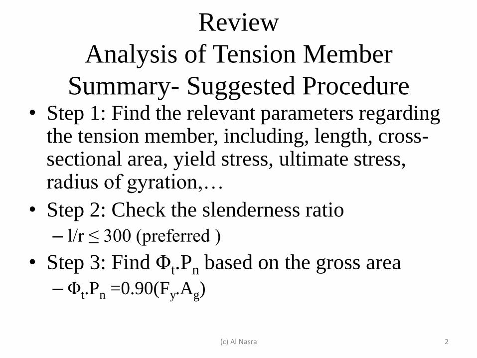
Review
Analysis of Tension Member
Summary- Suggested Procedure • Step 1: Find the relevant parameters regarding
the tension member, including, length, cross-sectional area, yield stress, ultimate stress, radius of gyration,…
• Step 2: Check the slenderness ratio
– l/r ≤ 300 (preferred )
• Step 3: Find Φt.Pn based on the gross area
– Φt.Pn =0.90(Fy.Ag)
(c) Al Nasra 2
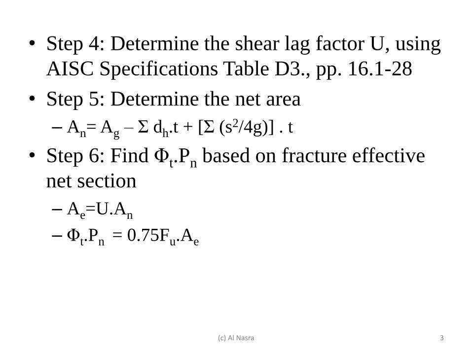
• Step 4: Determine the shear lag factor U, using
AISC Specifications Table D3., pp. 16.1-28
• Step 5: Determine the net area
– An= Ag – Σ dh.t + [Σ (s2/4g)] . t
• Step 6: Find Φt.Pn based on fracture effective
net section
– Ae=U.An
– Φt.Pn = 0.75Fu.Ae
(c) Al Nasra 3
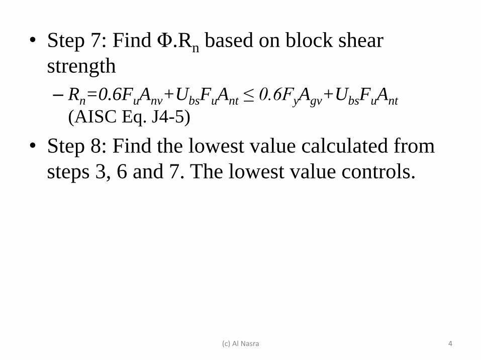
• Step 7: Find Φ.Rn based on block shear
strength
– Rn=0.6FuAnv+UbsFuAnt ≤ 0.6FyAgv+UbsFuAnt
(AISC Eq. J4-5)
• Step 8: Find the lowest value calculated from
steps 3, 6 and 7. The lowest value controls.
(c) Al Nasra 4
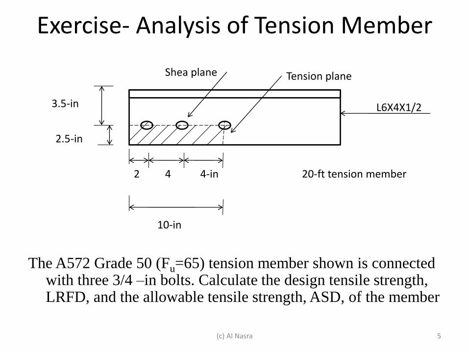
Exercise- Analysis of Tension Member
The A572 Grade 50 (Fu=65) tension member shown is connected
with three 3/4 –in bolts. Calculate the design tensile strength, LRFD, and the allowable tensile strength, ASD, of the member
Shea plane Tension plane
2 4 4-in
10-in
3.5-in
2.5-in
L6X4X1/2
20-ft tension member
(c) Al Nasra 5
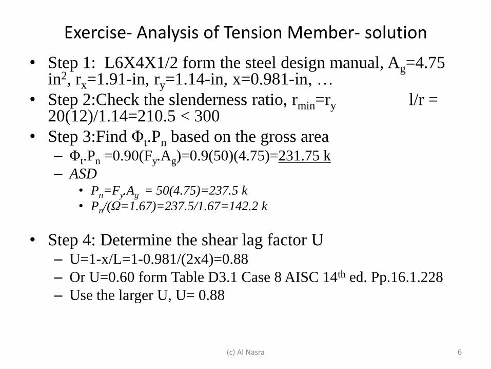
Exercise- Analysis of Tension Member- solution
• Step 1: L6X4X1/2 form the steel design manual, Ag=4.75 in2, rx=1.91-in, ry=1.14-in, x=0.981-in, …
• Step 2:Check the slenderness ratio, rmin=ry l/r = 20(12)/1.14=210.5 < 300
• Step 3:Find Φt.Pn based on the gross area – Φt.Pn =0.90(Fy.Ag)=0.9(50)(4.75)=231.75 k
– ASD • Pn=Fy.Ag = 50(4.75)=237.5 k
• Pn/(Ω=1.67)=237.5/1.67=142.2 k
• Step 4: Determine the shear lag factor U – U=1-x/L=1-0.981/(2x4)=0.88
– Or U=0.60 form Table D3.1 Case 8 AISC 14th ed. Pp.16.1.228
– Use the larger U, U= 0.88
(c) Al Nasra 6
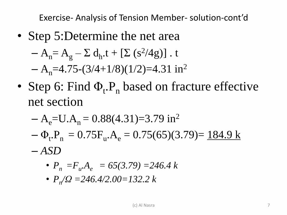
Exercise- Analysis of Tension Member- solution-cont’d
• Step 5:Determine the net area
– An= Ag – Σ dh.t + [Σ (s2/4g)] . t
– An=4.75-(3/4+1/8)(1/2)=4.31 in2
• Step 6: Find Φt.Pn based on fracture effective
net section
– Ae=U.An = 0.88(4.31)=3.79 in2
– Φt.Pn = 0.75Fu.Ae = 0.75(65)(3.79)= 184.9 k
– ASD
• Pn =Fu.Ae = 65(3.79) =246.4 k
• Pn/Ω =246.4/2.00=132.2 k
(c) Al Nasra 7
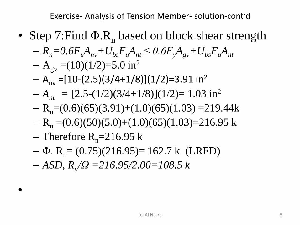
Exercise- Analysis of Tension Member- solution-cont’d
• Step 7:Find Φ.Rn based on block shear strength
– Rn=0.6FuAnv+UbsFuAnt ≤ 0.6FyAgv+UbsFuAnt
– Agv =(10)(1/2)=5.0 in2
– Anv =[10-(2.5)(3/4+1/8)](1/2)=3.91 in2
– Ant = [2.5-(1/2)(3/4+1/8)](1/2)= 1.03 in2
– Rn=(0.6)(65)(3.91)+(1.0)(65)(1.03) =219.44k
– Rn =(0.6)(50)(5.0)+(1.0)(65)(1.03)=216.95 k
– Therefore Rn=216.95 k
– Φ. Rn= (0.75)(216.95)= 162.7 k (LRFD)
– ASD, Rn/Ω =216.95/2.00=108.5 k
•
(c) Al Nasra 8
Exercise- Analysis of Tension Member- solution-cont’d
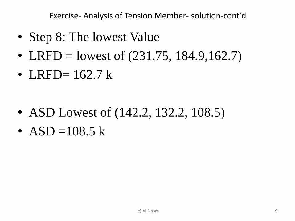
• Step 8: The lowest Value
• LRFD = lowest of (231.75, 184.9,162.7)
• LRFD= 162.7 k
• ASD Lowest of (142.2, 132.2, 108.5)
• ASD =108.5 k
(c) Al Nasra 9
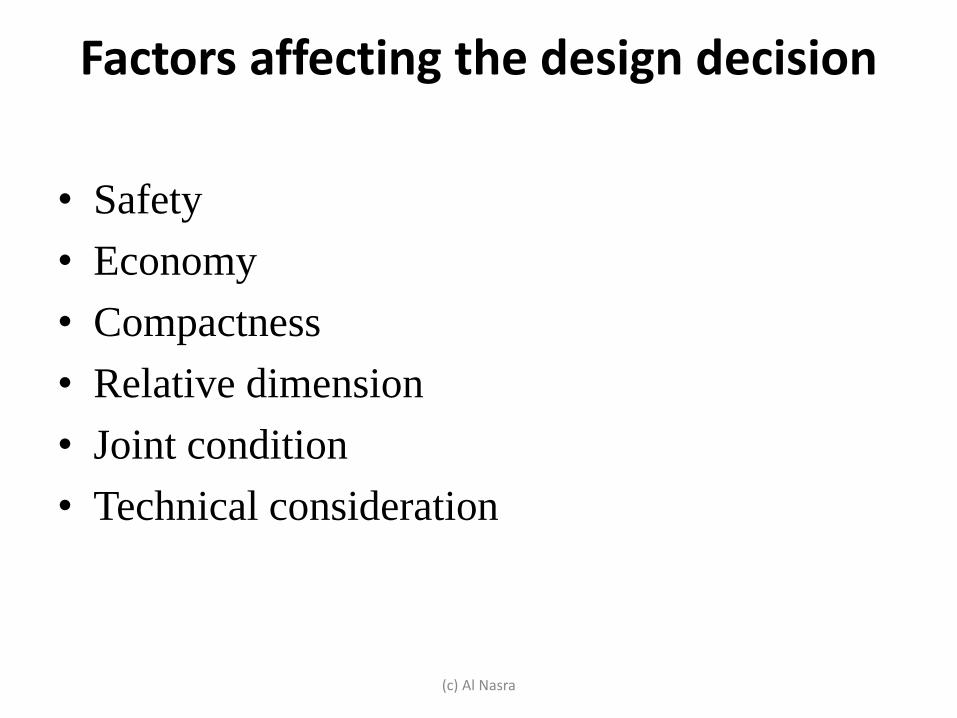
Factors affecting the design decision
• Safety
• Economy
• Compactness
• Relative dimension
• Joint condition
• Technical consideration
(c) Al Nasra
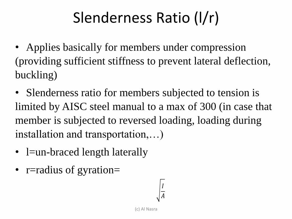
Slenderness Ratio (l/r)
• Applies basically for members under compression
(providing sufficient stiffness to prevent lateral deflection,
buckling)
• Slenderness ratio for members subjected to tension is
limited by AISC steel manual to a max of 300 (in case that
member is subjected to reversed loading, loading during
installation and transportation,…)
• l=un-braced length laterally
• r=radius of gyration=
(c) Al Nasra
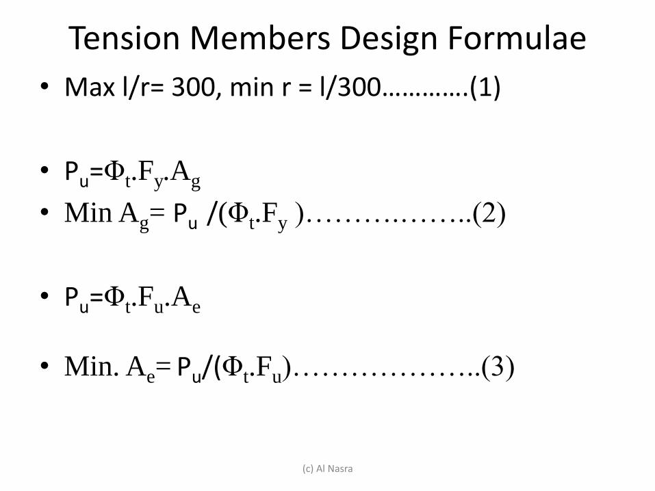
Tension Members Design Formulae
• Max l/r= 300, min r = l/300………….(1)
• Pu=Φt.Fy.Ag
• Min Ag= Pu /(Φt.Fy )……….……..(2)
• Pu=Φt.Fu.Ae
• Min. Ae= Pu/(Φt.Fu)………………..(3)
(c) Al Nasra
Tension Members Design Formulae
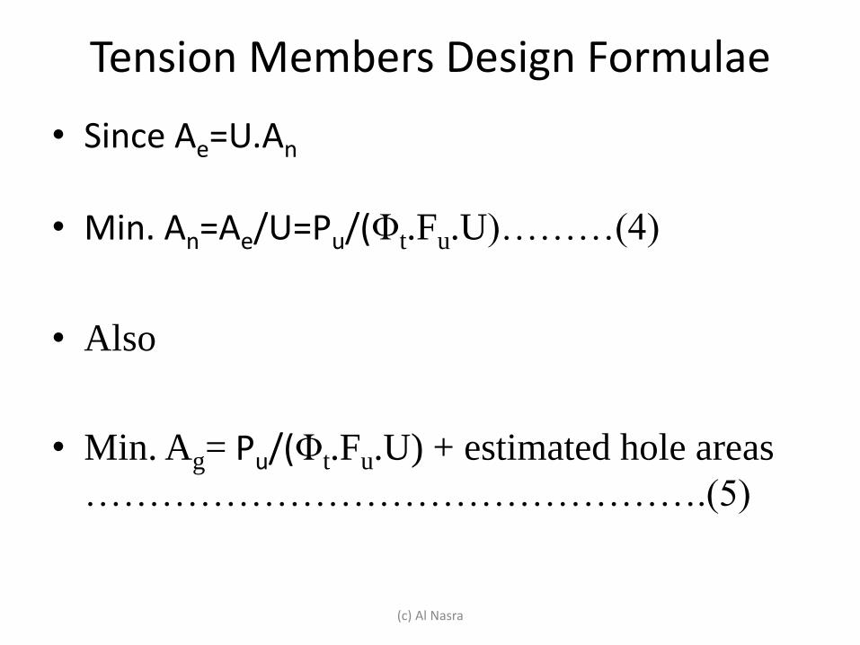
• Since Ae=U.An
• Min. An=Ae/U=Pu/(Φt.Fu.U)………(4)
• Also
• Min. Ag= Pu/(Φt.Fu.U) + estimated hole areas
………………………………………….(5)
(c) Al Nasra
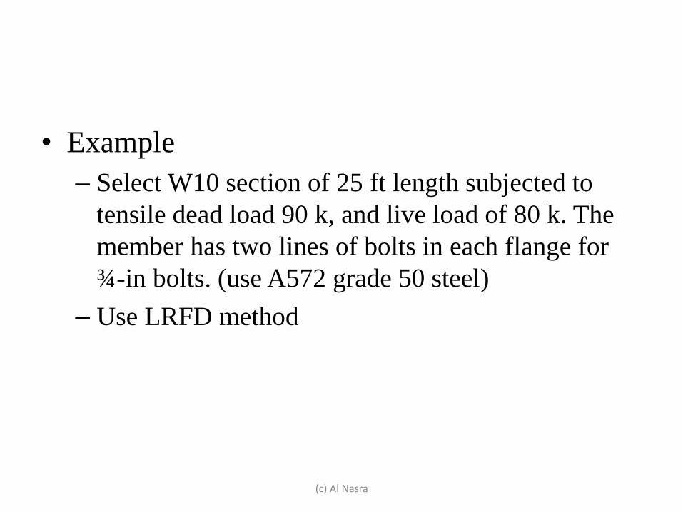
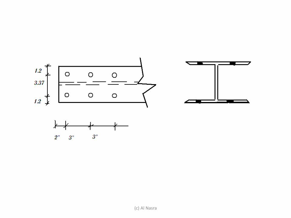
• Example
– Select W10 section of 25 ft length subjected to
tensile dead load 90 k, and live load of 80 k. The
member has two lines of bolts in each flange for
¾-in bolts. (use A572 grade 50 steel)
– Use LRFD method
(c) Al Nasra
(c) Al Nasra
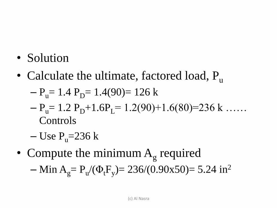
• Solution
• Calculate the ultimate, factored load, Pu
– Pu= 1.4 PD= 1.4(90)= 126 k
– Pu= 1.2 PD+1.6PL= 1.2(90)+1.6(80)=236 k ……
Controls
– Use Pu=236 k
• Compute the minimum Ag required
– Min Ag= Pu/(ΦtFy)= 236/(0.90x50)= 5.24 in2
(c) Al Nasra
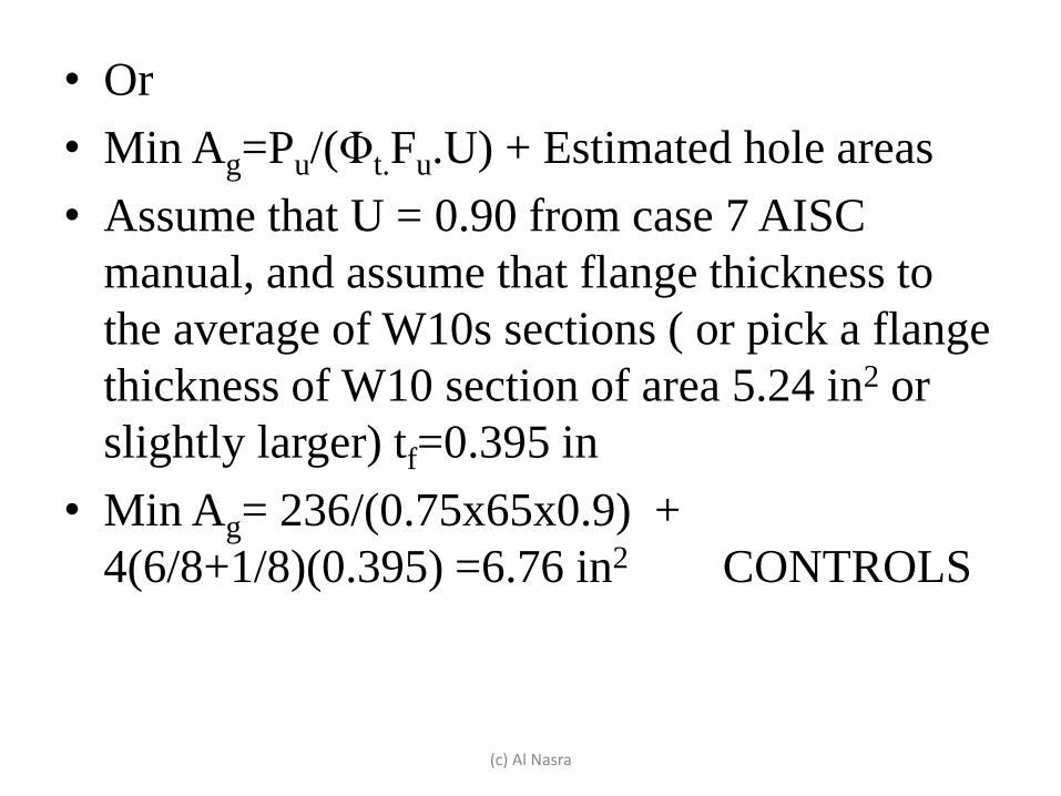
• Or
• Min Ag=Pu/(Φt.Fu.U) + Estimated hole areas
• Assume that U = 0.90 from case 7 AISC
manual, and assume that flange thickness to
the average of W10s sections ( or pick a flange
thickness of W10 section of area 5.24 in2 or
slightly larger) tf=0.395 in
• Min Ag= 236/(0.75x65x0.9) +
4(6/8+1/8)(0.395) =6.76 in2 CONTROLS
(c) Al Nasra
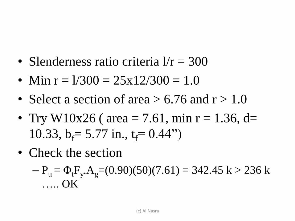
• Slenderness ratio criteria l/r = 300
• Min r = l/300 = 25x12/300 = 1.0
• Select a section of area > 6.76 and r > 1.0
• Try W10x26 ( area = 7.61, min r = 1.36, d=
10.33, bf= 5.77 in., tf= 0.44”)
• Check the section
– Pu = ΦtFy.Ag=(0.90)(50)(7.61) = 342.45 k > 236 k
….. OK
(c) Al Nasra
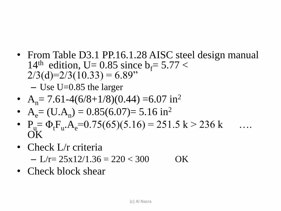
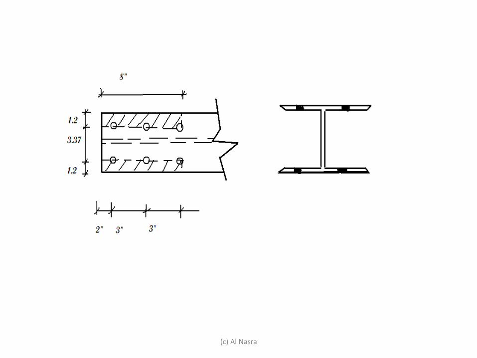
• From Table D3.1 PP.16.1.28 AISC steel design manual 14th edition, U= 0.85 since bf= 5.77 < 2/3(d)=2/3(10.33) = 6.89” – Use U=0.85 the larger
• An= 7.61-4(6/8+1/8)(0.44) =6.07 in2
• Ae= (U.An) = 0.85(6.07)= 5.16 in2
• Pu= ΦtFu.Ae=0.75(65)(5.16) = 251.5 k > 236 k …. OK
• Check L/r criteria – L/r= 25x12/1.36 = 220 < 300 OK
• Check block shear
(c) Al Nasra
(c) Al Nasra
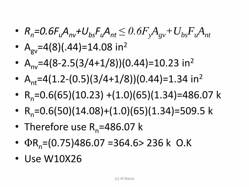
• Rn=0.6FuAnv+UbsFuAnt ≤ 0.6FyAgv+UbsFuAnt
• Agv=4(8)(.44)=14.08 in2
• Anv=4(8-2.5(3/4+1/8))(0.44)=10.23 in2
• Ant=4(1.2-(0.5)(3/4+1/8))(0.44)=1.34 in2
• Rn=0.6(65)(10.23) +(1.0)(65)(1.34)=486.07 k
• Rn=0.6(50)(14.08)+(1.0)(65)(1.34)=509.5 k
• Therefore use Rn=486.07 k
• ΦRn=(0.75)486.07 =364.6> 236 k O.K
• Use W10X26
(c) Al Nasra
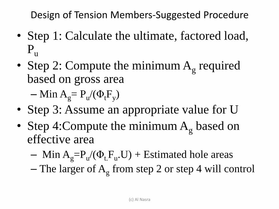
Design of Tension Members-Suggested Procedure
• Step 1: Calculate the ultimate, factored load, Pu
• Step 2: Compute the minimum Ag required based on gross area
– Min Ag= Pu/(ΦtFy)
• Step 3: Assume an appropriate value for U
• Step 4:Compute the minimum Ag based on effective area
– Min Ag=Pu/(Φt.Fu.U) + Estimated hole areas
– The larger of Ag from step 2 or step 4 will control
(c) Al Nasra
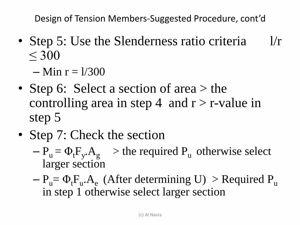
Design of Tension Members-Suggested Procedure, cont’d
• Step 5: Use the Slenderness ratio criteria l/r ≤ 300
– Min r = l/300
• Step 6: Select a section of area > the controlling area in step 4 and r > r-value in step 5
• Step 7: Check the section
– Pu = ΦtFy.Ag > the required Pu otherwise select larger section
– Pu= ΦtFu.Ae (After determining U) > Required Pu in step 1 otherwise select larger section
(c) Al Nasra
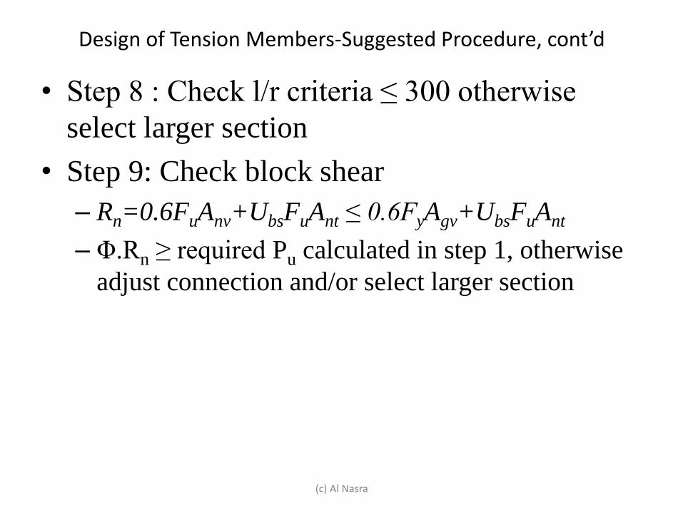
Design of Tension Members-Suggested Procedure, cont’d
• Step 8 : Check l/r criteria ≤ 300 otherwise
select larger section
• Step 9: Check block shear
– Rn=0.6FuAnv+UbsFuAnt ≤ 0.6FyAgv+UbsFuAnt
– Φ.Rn ≥ required Pu calculated in step 1, otherwise
adjust connection and/or select larger section
(c) Al Nasra
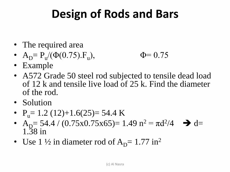
Design of Rods and Bars
• The required area
• AD= Pu/(Φ(0.75).Fu), Φ= 0.75
• Example
• A572 Grade 50 steel rod subjected to tensile dead load of 12 k and tensile live load of 25 k. Find the diameter of the rod.
• Solution
• Pu= 1.2 (12)+1.6(25)= 54.4 K
• AD= 54.4 / (0.75x0.75x65)= 1.49 n2 = πd2/4 d= 1.38 in
• Use 1 ½ in diameter rod of AD= 1.77 in2
(c) Al Nasra
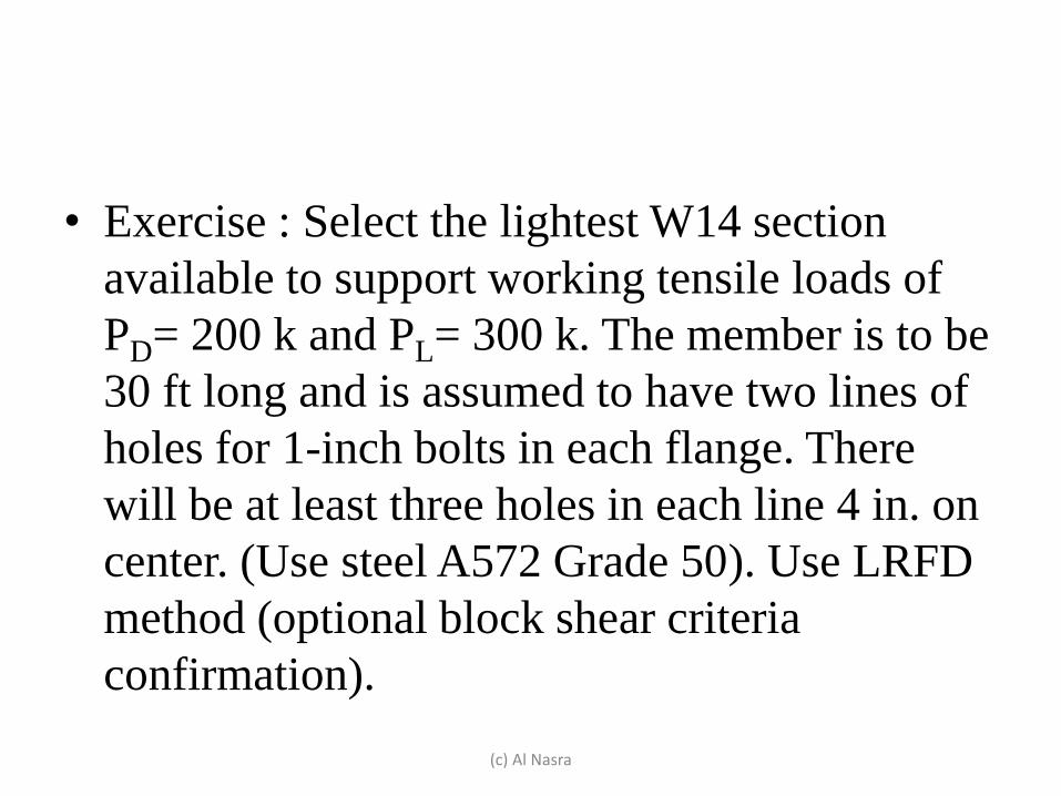
• Exercise : Select the lightest W14 section
available to support working tensile loads of
PD= 200 k and PL= 300 k. The member is to be
30 ft long and is assumed to have two lines of
holes for 1-inch bolts in each flange. There
will be at least three holes in each line 4 in. on
center. (Use steel A572 Grade 50). Use LRFD
method (optional block shear criteria
confirmation).
(c) Al Nasra
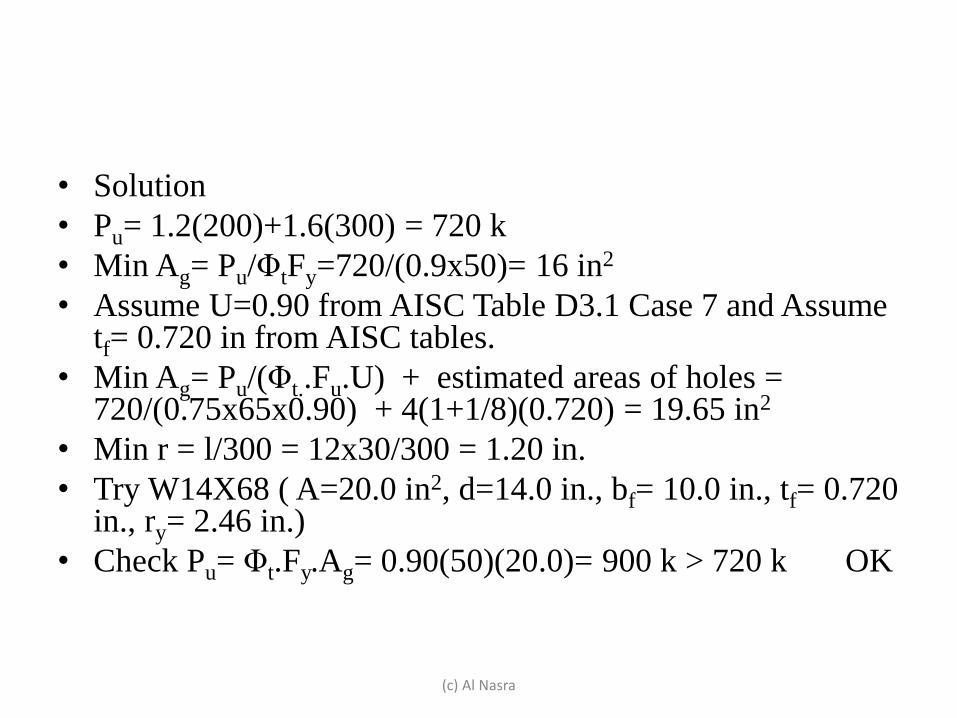
• Solution
• Pu= 1.2(200)+1.6(300) = 720 k
• Min Ag= Pu/ΦtFy=720/(0.9x50)= 16 in2
• Assume U=0.90 from AISC Table D3.1 Case 7 and Assume tf= 0.720 in from AISC tables.
• Min Ag= Pu/(Φt..Fu.U) + estimated areas of holes = 720/(0.75x65x0.90) + 4(1+1/8)(0.720) = 19.65 in2
• Min r = l/300 = 12x30/300 = 1.20 in.
• Try W14X68 ( A=20.0 in2, d=14.0 in., bf= 10.0 in., tf= 0.720 in., ry= 2.46 in.)
• Check Pu= Φt.Fy.Ag= 0.90(50)(20.0)= 900 k > 720 k OK
(c) Al Nasra

(c) Al Nasra
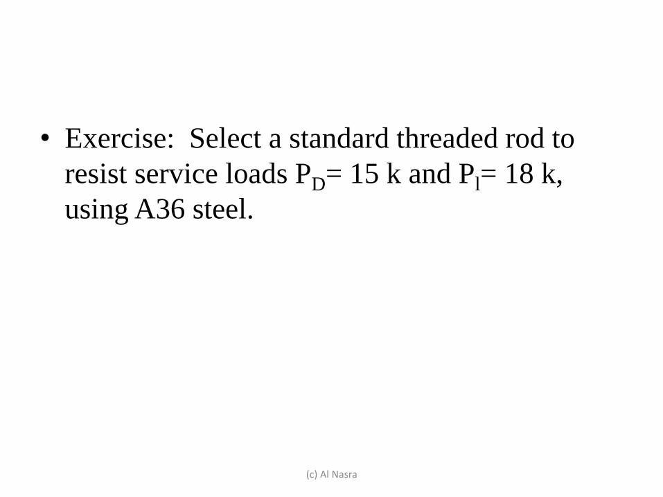
• Exercise: Select a standard threaded rod to
resist service loads PD= 15 k and Pl= 18 k,
using A36 steel.
(c) Al Nasra

(c) Al Nasra
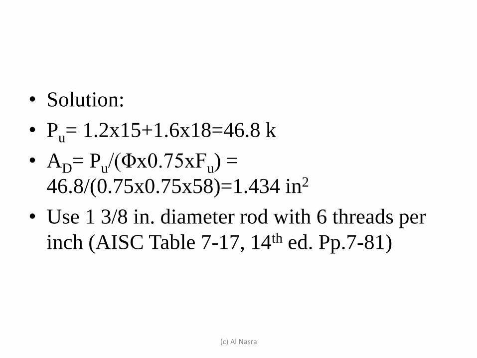
• Solution:
• Pu= 1.2x15+1.6x18=46.8 k
• AD= Pu/(Φx0.75xFu) =
46.8/(0.75x0.75x58)=1.434 in2
• Use 1 3/8 in. diameter rod with 6 threads per
inch (AISC Table 7-17, 14th ed. Pp.7-81)
(c) Al Nasra