Embed Size (px)
Citation preview

University of Anbar Steel Structures (DWE4336)
College of Engineering Dr. Ahmed T. Noaman
Department of Dams & Water Resources Eng. Phase: 4
Semester II (2018-2019)
23
Chapter Two
Tension Members
Tension members are members subjected to direct axial tension force, like:
See parts of AISC – M – LRFD / page (5 – 1) and Ch. D – Specifications p.
(16.1-282).

University of Anbar Steel Structures (DWE4336)
College of Engineering Dr. Ahmed T. Noaman
Department of Dams & Water Resources Eng. Phase: 4
Semester II (2018-2019)
24
(1) Types of Tension Members:
1 - cable is a flexible tension member consisting of one or more groups of
wires.
2 – Rods and Bars
used in bracing system, as in towers, sag rods for purlins in sloping roofs.
upset end threaded end
3 – Eye bars and pin – connected plates:
see page AISC – LRFD page D/(5 – 30)
4 – Structural shapes:
5 – Built – up members
they are combination of two or more shapes, like:
double angle double channel built – up plate and angle shape

University of Anbar Steel Structures (DWE4336)
College of Engineering Dr. Ahmed T. Noaman
Department of Dams & Water Resources Eng. Phase: 4
Semester II (2018-2019)
25
(2) Net Area:
It refers to the gross cross – sectional area of a member minus any holes
σ
≈ 3σ
Theoretical Actual
(3) Determining of Net Areas:
For rivet and bolted connections: t
Area– 1 for one row (line) holes
Net area An = t (b – d)
d
Area – 2 for two row or more than one row:
An = t (B – 2d)
In general:
An = t (B – nd) n: number of bolts
A – 3 Staggered Distribution:
Section ABE = An1 = t (B – d)
B B
T T

University of Anbar Steel Structures (DWE4336)
College of Engineering Dr. Ahmed T. Noaman
Department of Dams & Water Resources Eng. Phase: 4
Semester II (2018-2019)
26
ABCD
Sect. ABCD An2 = t (B – 2d + g4
S2
)
S (stagger) = spacing of adjacent holes parallel to load direction
g (gage) = the gage distance transverse to load direction
The smaller of An1 , An2 represents the critical net area
In general:
An = t (B - ∑ d + n g4
S2
)
Where: n = no. of staggered (zigzag) lines
Note: d = Ф + 1/8 (because of fabricating)
B – For Relatively Short Fitting (splice and gusset plates)
column
T
T. M
Gusset
plate
splice

University of Anbar Steel Structures (DWE4336)
College of Engineering Dr. Ahmed T. Noaman
Department of Dams & Water Resources Eng. Phase: 4
Semester II (2018-2019)
27
An 0.85 Ag AISC – LRFD (Ch. J – Specifications)
Example1: Determine the critical net area for the 1/2 in thick plate shown in
fig. below. The holes are punched for 3/4 in bolts.
Solution:
An = t (B - ∑ d + n g4
S2
)
An ABCD = 0.5 (11 – 2 (4
3
8
1 )) = 4.625 in
2
An ABCEF = 0.5 (11 – 3 (8
7) +
3*4
)3( 2
) = 4.56 in2 control
An ABEF = 0.5 (11 – 2 (8
7) +
6*4
)3( 2
) = 4.813 in2
(4) Effective Net Area (Ae) see parts D ASCE M - LRFD
- When a member other than a flat plate or bar is loaded in axial tension
until failure occurs across its net section , its' actual tensile stress will be
less than the tensile strength of the steel, unless all of various elements
which make up the section are connected so stress is transferred uniformly
across the section. The reason of the reduced strength of the member is the
concentration of shear stress, called shear lag

University of Anbar Steel Structures (DWE4336)
College of Engineering Dr. Ahmed T. Noaman
Department of Dams & Water Resources Eng. Phase: 4
Semester II (2018-2019)
28
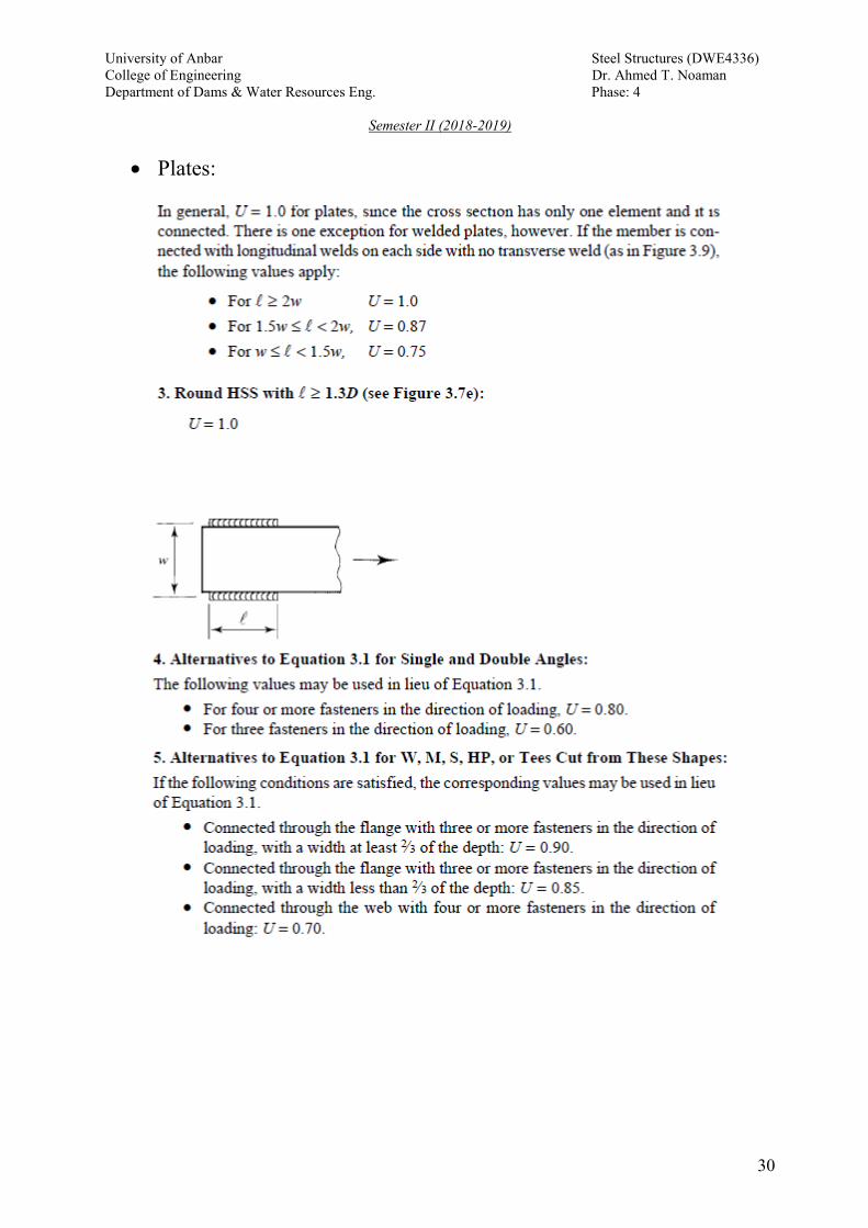
Ae = U An U 1
U = 1 – L
x 0.9
x = distance from the centroid of the connected area to the plane of
connection.
L = length of the connection in the direction of load
Generally:
If the force is transmitted directly to each of the cross sectional elements of
a member by connectors : Ae = An
Bolted or Riveted Members:
If the load is transmitted by bolts or rivets through some but not all of the
elements of the member, value of Ae is:
Ae = U An

University of Anbar Steel Structures (DWE4336)
College of Engineering Dr. Ahmed T. Noaman
Department of Dams & Water Resources Eng. Phase: 4
Semester II (2018-2019)
29
University of Anbar Steel Structures (DWE4336)
College of Engineering Dr. Ahmed T. Noaman
Department of Dams & Water Resources Eng. Phase: 4
Semester II (2018-2019)
30
Plates:

University of Anbar Steel Structures (DWE4336)
College of Engineering Dr. Ahmed T. Noaman
Department of Dams & Water Resources Eng. Phase: 4
Semester II (2018-2019)
31
The Design Philosophy for LRFD Method for Tension Members
Requirements for Tension members:

University of Anbar Steel Structures (DWE4336)
College of Engineering Dr. Ahmed T. Noaman
Department of Dams & Water Resources Eng. Phase: 4
Semester II (2018-2019)
32
The design strength is taken as the smaller of the following:
1 – Yielding failure of the cross section area
2 – Fracture of the net section area
3 - Slenderness ratio requirement (recommendation)
L/r ≤ 300
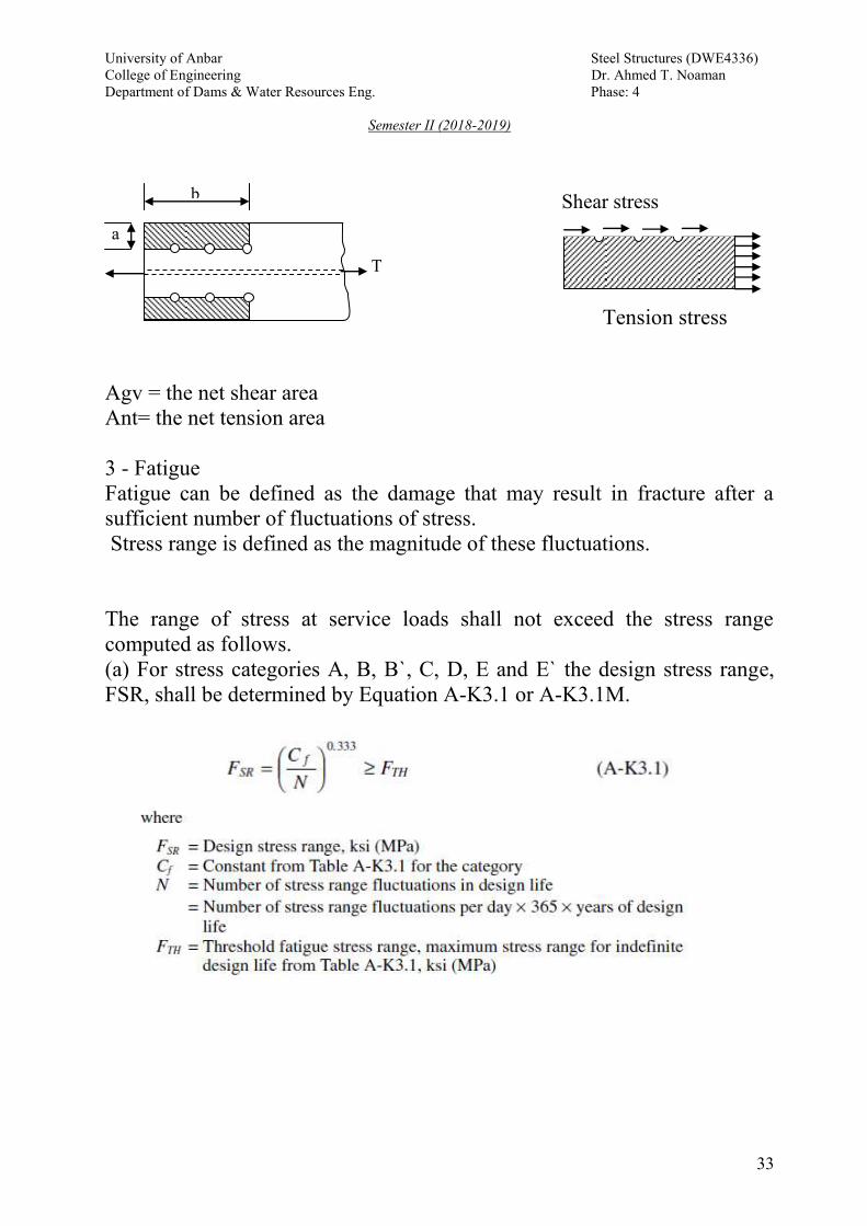
4 - Block Shear Rapture
Φ = 0.75
Block shear is a combined tensile/shear tearing out of an entire section of
a connection. Common examples are shown below:
For such a failure to occur, there are two possible mechanisms: (1) Shear
rupture + tensile yielding; and (2) Shear yielding + tensile rupturing.
University of Anbar Steel Structures (DWE4336)
College of Engineering Dr. Ahmed T. Noaman
Department of Dams & Water Resources Eng. Phase: 4
Semester II (2018-2019)
33
Tension stress
Agv = the net shear area
Ant= the net tension area
3 - Fatigue
Fatigue can be defined as the damage that may result in fracture after a
sufficient number of fluctuations of stress.
Stress range is defined as the magnitude of these fluctuations.
The range of stress at service loads shall not exceed the stress range
computed as follows.
(a) For stress categories A, B, B`, C, D, E and E` the design stress range,
FSR, shall be determined by Equation A-K3.1 or A-K3.1M.
b
a
T
Shear stress

University of Anbar Steel Structures (DWE4336)
College of Engineering Dr. Ahmed T. Noaman
Department of Dams & Water Resources Eng. Phase: 4
Semester II (2018-2019)
34
Tutorial – Tension Members
Ex1: Determine the net area of the (3/8 *8 in) plate shown in the fig.
below if the plate is connected at its end with two lines of (¾) in bolts.
Solution
Ag = (3/8) * 8 = 3 in.
An = t (B – nd) = (3/8) (8 – 2 *( )8
1
4
3 ) = 2.43 in
2
Ex2: Determine the net areas for the angle (6 * 4 *1/2 in) if there are 6
holes of (5/16)" diameter as shown below.
Solution
Dimension: see AISC
Sec Ag g g1 g2
L 6*4*1/2 4.75 3 ½ 2 ¼ 2 1/2
ABCD : An = Ag – 2*(1/2) ( )16
1
16
5 = 4.375 in
2
ABECD : An = Ag – 3(1/2) ( )16
1
16
5 +[(1/2) )
)5.2(*4
)3((
2
(1/2)
))25.5(*4
)3((
2
] = 5.37 in2

University of Anbar Steel Structures (DWE4336)
College of Engineering Dr. Ahmed T. Noaman
Department of Dams & Water Resources Eng. Phase: 4
Semester II (2018-2019)
35
Then path ABCD critical An = 4.375 in2
Ex3: For the two lines of bolt holes shown in fig. determine the pitch
which will give a net area DEFG equal to the one along ABC. The holes
are punched for ¾ in bolts.
Solution
ABC : An = 6 – (1)(7/8) = 5.125 in2
DEFG: An = 6 – (2)(7/8) + 2*4
S2
= 4.25 + 8
S2
ABC = DEFG then 5.125 =4.25 + 8
S2
S = 2.65 in.
Ex4: Determine the net area for the C15*33.9 shown in fig. below. Holes
are for ¾ in bolts.

University of Anbar Steel Structures (DWE4336)
College of Engineering Dr. Ahmed T. Noaman
Department of Dams & Water Resources Eng. Phase: 4
Semester II (2018-2019)
36
Solution:
Gross area = Ag = 9.96 in2
Path ABCD : An = 9.96 – 0.65 )8
1
4
3(4.0)
8
1
4
3( = 9.04 in
2
Path ABECD :
An = 9.96 – 0.65 2
)4.065.0(
6.4*4
3)4.0(
9*4
3)
8
1
4
3(4.0*2)
8
1
4
3(
22 =
9.048 in2
Path ABCFG: An = 9.96 – 2 (0.65*(7/8)) – 0.4* (7/8) +2
)4.065.0(
6.4*4
32
= 8.7293 in2 critical (Why?)
Path ABECFG:
An = 9.96 – 2*(7/8)(0.65) – 2*(7/8)(0.4) +
2
)4.065.0(
6.4*4
3)2()4.0(
9*4
3(
22
= 8.736 in2
Ex5: Determine the max. length required by AISC for a tension member
where cross – section is Plate of 7*1 ½ in.
Solution:
Check least r = rx
in130Lthen,300*433.0L,300minr/L
in5.10A,in433.05.10/97.1rx
in97.112
)5.1(*7
12
btIx,A/Ixrx
22
4
33
University of Anbar Steel Structures (DWE4336)
College of Engineering Dr. Ahmed T. Noaman
Department of Dams & Water Resources Eng. Phase: 4
Semester II (2018-2019)
37
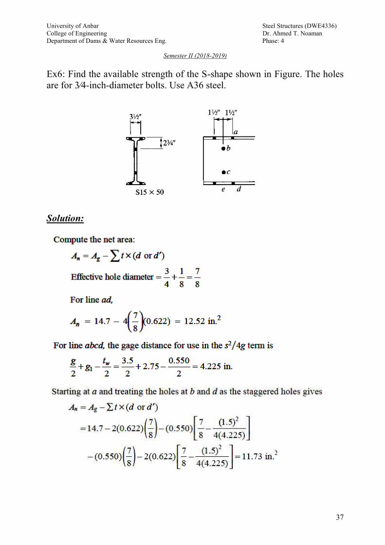
Ex6: Find the available strength of the S-shape shown in Figure. The holes
are for 3⁄4-inch-diameter bolts. Use A36 steel.
Solution:

University of Anbar Steel Structures (DWE4336)
College of Engineering Dr. Ahmed T. Noaman
Department of Dams & Water Resources Eng. Phase: 4
Semester II (2018-2019)
38
Ex7: Select an 8 in. W-shape, ASTM A992, to carry a dead load of 30 kips
and a live load of 90 kips in tension. The member is 25 ft long. Verify the
member strength by LRFD with the bolted end connection shown. Verify
that the member satisfies the recommended slenderness limit
Solution:
Pu = 1.2 (30) + 1.6 (90) = 180 kips
ΦPn = Pu , ΦPn = 0.9 Fy Ag , 0.9 Fy Ag = Pu
Min Ag = 180/ (0.9*50) = 4 in2
University of Anbar Steel Structures (DWE4336)
College of Engineering Dr. Ahmed T. Noaman
Department of Dams & Water Resources Eng. Phase: 4
Semester II (2018-2019)
39
Min Ag = (Pu/0.75FuU)+ estimated hole areas
(Assume U = 0.9 and thickness of flange about 0.315 after loking at W8
sections which have an area of about 4 in2)
Min Ag = (180/0.75*65*0.9) + 4 *0.315 *(3/4+1/8) =5.2 in2
Try W8*21 (Ag = 6.16 in2, bf = 5.27 in. tf = 0.400 in. d = 8.28 in., ry =
1.26 in.)
Pu = ΦFy Ag = 0.9 *50 * 6.16 = 277.9 kips > 180 O.K.
Pu = Φ Fu Ae , An = 6.16 – 4 * (3/4 +1/8) * 0.4 = 4.76 in2
U = ? bf/ d = 5.27/ 8.28 = 0.636 < (2/3= 0.666) then U = 0.85
Ae = 0.85 *4.76 = 4.046 in2 ,
Pu = 0.75*65*4.046 = 197.2 kips > 180 O.K.
L/rmin = 25*12 / 1.26 = 238 < 300 O.K.
Then use W8*21
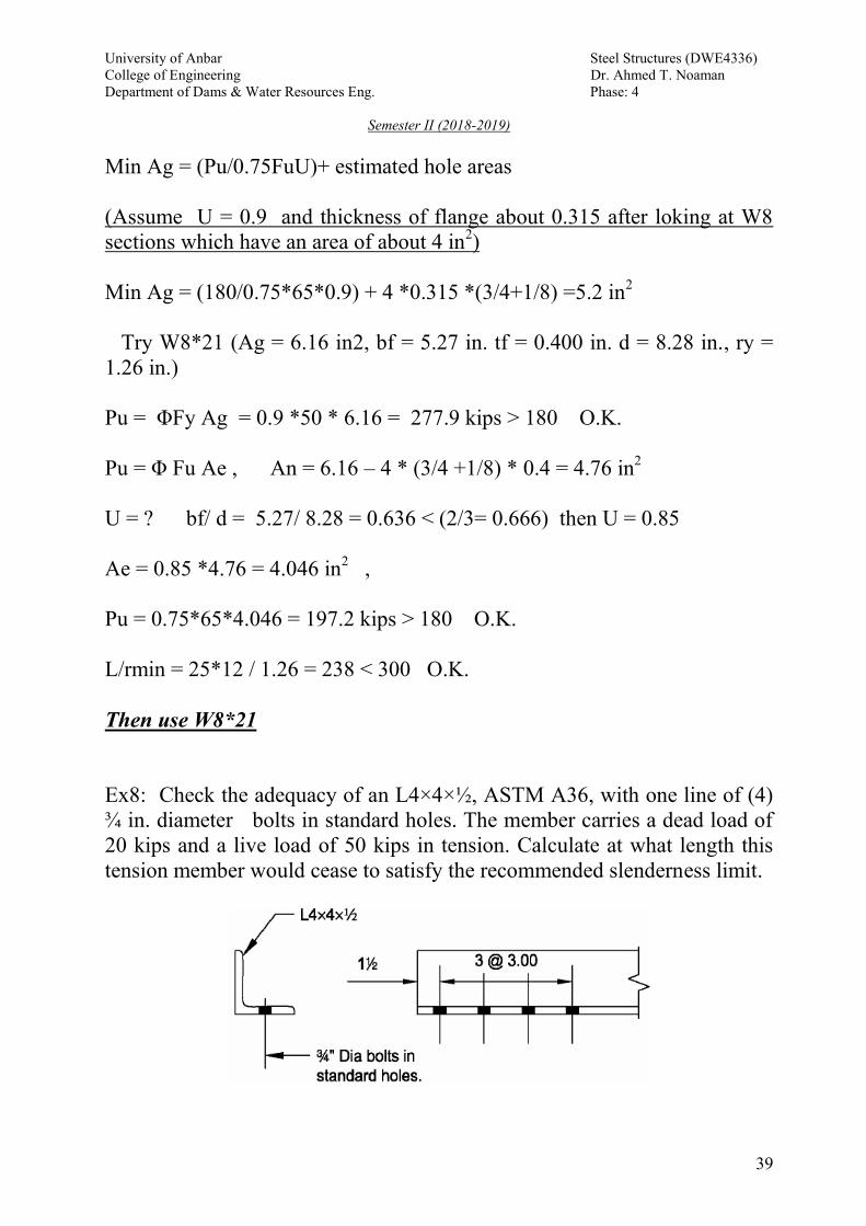
Ex8: Check the adequacy of an L4×4×½, ASTM A36, with one line of (4)
¾ in. diameter bolts in standard holes. The member carries a dead load of
20 kips and a live load of 50 kips in tension. Calculate at what length this
tension member would cease to satisfy the recommended slenderness limit.

University of Anbar Steel Structures (DWE4336)
College of Engineering Dr. Ahmed T. Noaman
Department of Dams & Water Resources Eng. Phase: 4
Semester II (2018-2019)
40
Solution:
Fy = 36 ksi Fu = 58 ksi
L4×4×½ , Ag = 3.75 in2 , rz = 0.776 in.
Pu = 1.2(20 kips) + 1.6(60 kips) = 104 kips
ΦPn = 0.9 *36* 3.75 = 122 kips > 104 kip O.K.
Ae = UAn
An = 3.75 – (3/4+1/8) *0.5 = 3.31 in2
U = 0.8 case 8
Ae= 0.8*3.31 = 2.648 ,
ΦPn = 0.75 FuAe
ΦPn = 0.75 *58 * 2.648 = 115.2 kips > 104 kips O.K
L/rmin ≤ 300 then L = 300* 0.776 = 232.8 in = 19.4 ft
Then the length of this member must not be greater than 19.4 ft

University of Anbar Steel Structures (DWE4336)
College of Engineering Dr. Ahmed T. Noaman
Department of Dams & Water Resources Eng. Phase: 4
Semester II (2018-2019)
41
Ex9: See Figure below. A 5/8" in. thick eye bar member, ASTM A36,
carries a dead load of 25 kips and a live load of 15 kips in tension. The pin
diameter d is 3 in. Verify the strength by LRFD .
Solution
Plate ASTM A36 Fy = 36 ksi Fu = 58 ksi
Geometric Properties: Section D4.2
w = 3 in. b = 2.23 in. t = 0.625 in.
db = 3 in. dh = 3.03 in. R = 8.00 in.
Check dimensional requirements
1) t > ½ in. 0.625 in. > 0.500 in. o.k.
2) w < 8t 3.00 in. < 8(0.625 in.) = 5 in. o.k.
3) d > 7/8w 3.00 in. > 7/8 (3.00 in.) = 2.63 in. o.k.
4) dh < d + 1/32 in. 3.03 in. < 3.00 in. + (1/32 in.) = 3.03 in.
o.k.
5) R > dh + 2b 8.00 in. > 3.03 in. + 2(2.23 in.) = 7.50 in.
o.k.
6) 2/3w < b < 3/4w 2/3(3.00 in.) < 2.23 in. < 3/4(3.00 in.)
2.00 in. < 2.23 in. < 2.25 in. o.k.

University of Anbar Steel Structures (DWE4336)
College of Engineering Dr. Ahmed T. Noaman
Department of Dams & Water Resources Eng. Phase: 4
Semester II (2018-2019)
42
Pu = 1.2(25.0 kips) + 1.6(15.0 kips)= 54 kips
Calculate the available tensile yield strength at the eye bar body (at w)
Ag = 3.00 * (0.625) = 1.88 in2
ΦPn= 0.9 FyAg = 0.9 (36 ksi)(1.88 in2) = 60.9 kips > 54 kips O.K.
Ex10 : A 5 x ½ bar of A572 Gr. 50 steel is used as a tension member. It is
connected to a gusset plate with six 7/8 in. diameter bolts as shown in
below. Assume that the effective net area Ae equals the actual net area An
and compute the tensile design strength of the member.
Solution
• Gross section area = Ag = 5 x ½ = 2.5 in
2
• Net section area (An)
- Bolt diameter = db = 7/8 in.
- Hole diameter = dh = 7/8 + 1/8 in. = 1 in.
- Net section area = An = (5 – 2 x (1)) x ½ = 1.5 in
2
• Gross yielding design strength = φt P
n = φ
t F
y A
g
- Gross yielding design strength = 0.9 x 50 ksi x 2.5 in2
= 112.5 kips

University of Anbar Steel Structures (DWE4336)
College of Engineering Dr. Ahmed T. Noaman
Department of Dams & Water Resources Eng. Phase: 4
Semester II (2018-2019)
43
• Fracture design strength = φt P
n = φ
t F
u A
e
- Assume Ae = A
n (only for this problem)
- Fracture design strength = 0.75 x 65 ksi x 1.5 in2
= 73.125 kips
• Design strength of the member in tension = smaller of 73.125 kips and
112.5 kips
Therefore, design strength = 73.125 kips (net section fracture controls).
EX11: Find the design strength of the angle shown in figure below A36
steel is used and holes are for 7/8 in diameter bolts?
Solution
Compute the net width = 8 + 6 – 0.5 = 13.5 "
D of holes = 1/8 + 7/8 = 1 "
For line abdf : An = 6.75 - 0.5 * 2* *1 = 5.75 in2
For line abceg : An = 6.75 – 3(1/2) *1 + [(1/2) * ))5.2(*4
)5.1((
2
] = 5.365 in2
Then path abcdeg : An = 6.75 – 4 (1/2) *1 + (1/2) ))5.2(*4
)5.1((
2
(1/2)
))75.4(*4
)5.1((
2
+(1/2) ))3(*4
)5.1((
2
= 5.015 in2

University of Anbar Steel Structures (DWE4336)
College of Engineering Dr. Ahmed T. Noaman
Department of Dams & Water Resources Eng. Phase: 4
Semester II (2018-2019)
44
Ae = An = 5.015 in2
The design strength based on yielding φ P
n = φ
F
y A
g
φ P
n = o.9*36 * 6.75 = 219 kips
The design strength based on fracture φt P
n = φ
t F
u A
e
φ P
n = 0.75 * 58 * 5.015 = 218 kips
The design strength is 218 kips
EX12: For the member shown which is a single angle section connected
through one leg using four 1 in. diameter bolts. The center-to-center
distance of the bolts is 3 in. The edge distances are 2 in. Steel material is
A36. The factored load is 100 kips. Check block shear.
L4x3x1/2
Solution
Agv
= (9+2) x 0.5 = 5.5 in2
- Anv
= [11 - 3.5 x (1+1/8)] x 0.5 = 3.53 in2

University of Anbar Steel Structures (DWE4336)
College of Engineering Dr. Ahmed T. Noaman
Department of Dams & Water Resources Eng. Phase: 4
Semester II (2018-2019)
45
- Agt
= 2.0 x 0.5 = 1.0 in2
- Ant
= [2.0 - 0.5 x (1 + 1/8)] x 0.5 = 0.72 in2
Identify the governing equation:
- FuA
nt = 58 x 0.72 = 41.76 kips
- 0.6 FuA
nv = 0.6 x 58 x 3.53 = 122.844 in
2
, which is > FuA
nt
Calculate block shear strength
- φtR
n = 0.75 (0.6F
uA
nv + F
yA
gt) = 0.75 (122.84 + 36 x 1.0) = 119.133 kips
Which is greater than Pu = 100 kips. Therefore L4x3x1/2 is acceptable
EX13: Fink trusses spaced at 20 feet on centers support W6 × 12 purlins, as
shown in Figure. The purlins are supported at their midpoints by sag rods.
Use A36 steel and design the sag rods and the tie rod at the ridge for the
following service loads.
Metal deck: 2 psf
Built-up roof: 5 psf
Snow: 18 psf of horizontal projection of the roof surface
Purlin weight: 12 pounds per foot (lb/ft) of length
Solution
Calculate loads:
Tributary width for each sag rod = 20/2 = 10 ft
Tributary area for deck and built-up roof = 10*(46.6) = 466 ft2
Dead load (deck and roof) = (2 + 5)(466) = 3262 lb
Total purlin weight = 12*(10)*(9) = 1080 lb
Total dead load = 3262 + 1080 = 4342 lb
Tributary area for snow load = 10*(45) = 450 ft2
University of Anbar Steel Structures (DWE4336)
College of Engineering Dr. Ahmed T. Noaman
Department of Dams & Water Resources Eng. Phase: 4
Semester II (2018-2019)
46
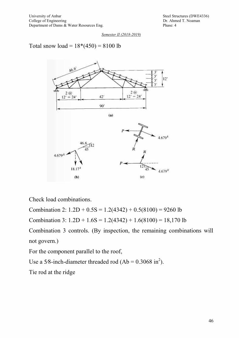
Total snow load = 18*(450) = 8100 lb
Check load combinations.
Combination 2: 1.2D + 0.5S = 1.2(4342) + 0.5(8100) = 9260 lb
Combination 3: 1.2D + 1.6S = 1.2(4342) + 1.6(8100) = 18,170 lb
Combination 3 controls. (By inspection, the remaining combinations will
not govern.)
For the component parallel to the roof,
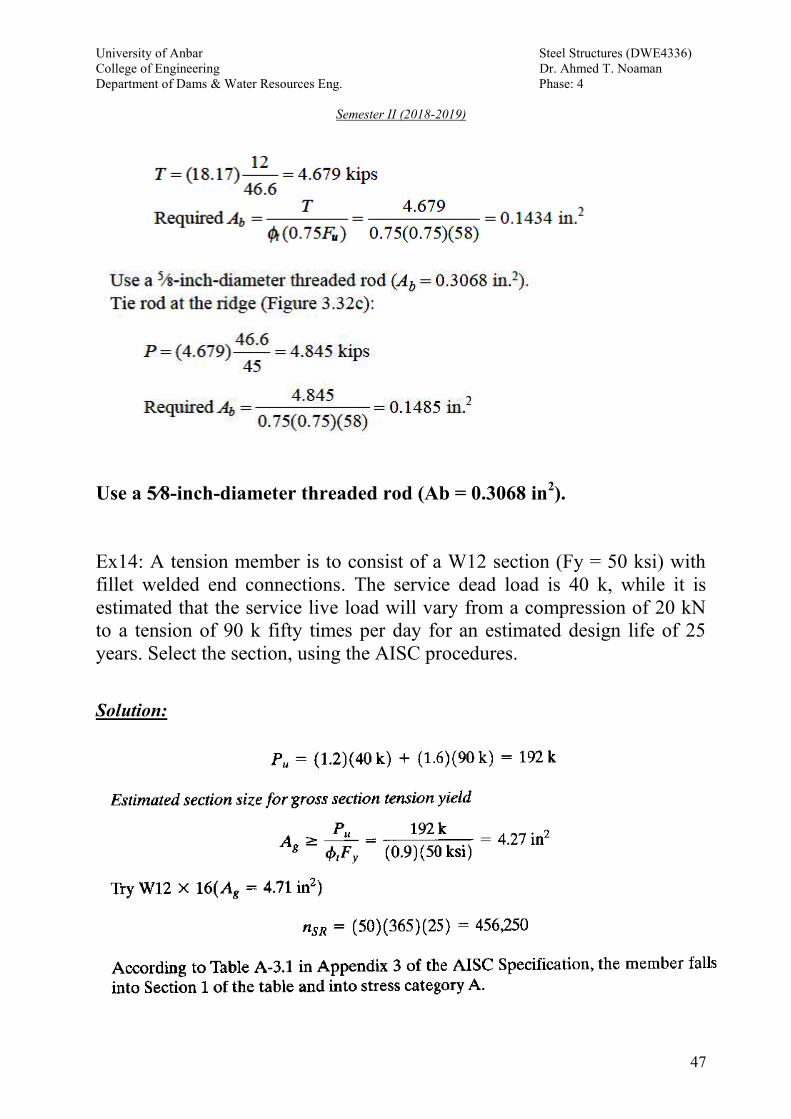
Use a 5⁄8-inch-diameter threaded rod (Ab = 0.3068 in2).
Tie rod at the ridge
University of Anbar Steel Structures (DWE4336)
College of Engineering Dr. Ahmed T. Noaman
Department of Dams & Water Resources Eng. Phase: 4
Semester II (2018-2019)
47
Use a 5⁄8-inch-diameter threaded rod (Ab = 0.3068 in2).
Ex14: A tension member is to consist of a W12 section (Fy = 50 ksi) with
fillet welded end connections. The service dead load is 40 k, while it is
estimated that the service live load will vary from a compression of 20 kN
to a tension of 90 k fifty times per day for an estimated design life of 25
years. Select the section, using the AISC procedures.
Solution:
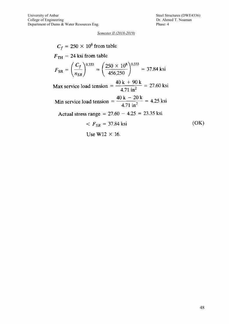
University of Anbar Steel Structures (DWE4336)
College of Engineering Dr. Ahmed T. Noaman
Department of Dams & Water Resources Eng. Phase: 4
Semester II (2018-2019)
48