Embed Size (px)
Citation preview

Design of Tension Members
Dr. S. RAVIRAJ*
Assistant Professor of Civil Engineering
Sri Jayachamarajendra College of Engineering, Mysore – 06
1.0 Introduction
The Tension member considered for the design is a linear member which
carries an axial pull. The members undergo extension due to this axial pull. This
is one of the common types of force transmitted in the structural system.
Tension members are very efficient since the entire cross section carries
uniform stress unlike flexural members. The tension members do not buckle
even when stressed beyond the elastic limit. Hence the design is not effected
by the type of section used i.e., Plastic, Compact or Semi-compact. Some of the
common examples of tension members in structures are; Bottom chord of pin
jointed roof trusses, bridges, transmission line and communication towers,
wind bracing system in multi-storey buildings, etc.
The objective of this exercise is to determine the tensile strength of a given
member having a specified end connection. The strength of these members is
influenced by several factors such as the length of connection, type of
connection (by bolts or welds), connection eccentricity, size and shape of
fasteners, net area of cross-section and shear lag at the end connection.
2.0 Types of Tension Members
The tension members may be made of single structural shapes. The standard
structural shapes of typical tension members are:
• Angle section • Tee section
• Channel section • Box section
• I section • Tubular section

The sections can also be built up using a number of the above structural
shapes.
Single angle members are economical but the connection produces eccentric
force in the member. These are generally used in towers and in trusses. Double
angle members are more rigid than single angle members. They are used in
roof trusses. Since there exists a gap of about 6 to 10 mm between the two
members (which depends on the thickness of the gusset plate), they are
generally interconnected at regular intervals so that they act as one integral
member. In the members of bridge trusses the tensile forces developed are
very large and hence require more rigid members. In these structures single
channel, single I-section, built-up channels, or built-up I-sections will be
generally used.
3.0 Behaviour of Tension Members
The load-deformation behavior of members subjected to uniform tensile stress
is similar to the load-deflection behavior of the corresponding basic material.
The typical stress-strain behavior of mild steel under axial tensile load is shown
in Fig. 1. The upper yield point is merged with the lower yield point for
convenience. The material shows a linear elastic behavior in the initial region
(O to A). The material undergoes sufficient yielding in portion A to B. Further
deformation leads to an increase in resistance, where the material strain
hardens (from B to C). The material reaches its ultimate stress at point C. The
stress decreases with increase in further deformation and breaks at D. The high
strength steel members do not exhibit the well defined yield point and the
yield region (Fig. 1). For such materials, the 0.2 percent proof stress is usually
taken as the yield stress (E).
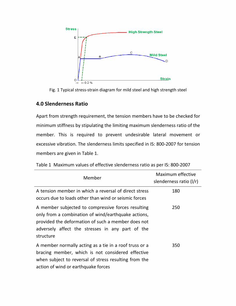
Fig. 1 Typical stress-strain diagram for mild steel and high strength steel
4.0 Slenderness Ratio
Apart from strength requirement, the tension members have to be checked for
minimum stiffness by stipulating the limiting maximum slenderness ratio of the
member. This is required to prevent undesirable lateral movement or
excessive vibration. The slenderness limits specified in IS: 800-2007 for tension
members are given in Table 1.
Table 1 Maximum values of effective slenderness ratio as per IS: 800-2007
Member Maximum effective
slenderness ratio (l/r)
A tension member in which a reversal of direct stress
occurs due to loads other than wind or seismic forces
180
A member subjected to compressive forces resulting
only from a combination of wind/earthquake actions,
provided the deformation of such a member does not
adversely affect the stresses in any part of the
structure
250
A member normally acting as a tie in a roof truss or a
bracing member, which is not considered effective
when subject to reversal of stress resulting from the
action of wind or earthquake forces
350

Members always in tension (other than pre-tensioned
members)
400
5.0 Shear Lag
The tensile force to a tension member is transferred by a gusset plate or by the
adjacent member connected to one of the legs either by bolting or welding.
This force which is transferred to one leg by the end connection locally gets
transferred as tensile stress over the entire cross section by shear. Hence, the
distribution of tensile stress on the section from the first bolt hole to the last
bolt hole will not be uniform. Hence, the connected leg will have higher
stresses at failure while the stresses in the outstanding leg will be relatively
lower. However, at sections far away from the end connection, the stress
distribution becomes more uniform. Here the stress transfer mechanism, i.e.,
the internal transfer of forces from one leg to the other (or flange to web, or
from one part to the other), will be by shear and because one part ‘lags’
behind the other, the phenomenon is referred to as ‘shear lag’.
The shear lag reduces the effectiveness of the component plates of a tension
member that are not connected directly to a gusset plate. The efficiency of a
tension member can be increased by reducing the area of such components
which are not directly connected at the ends. The shear lag effect reduces with
increase in the connection length.
6.0 Modes of Failure
The different modes of failure in tension members are
1. Gross section yielding
2. Net section rupture
3. Block shear failure

The strength of tension members under the different modes are failure, i.e.,
design strength due to yielding of gross section, Tdg, rupture of critical section,
Tdn and block shear Tdb are first determined. The design strength of a member
under axial tension, Td, is the lowest of the above three values.
6.1 Gross section yielding
Steel members (plates, angles, etc.) without bolt holes can sustain loads up to
the ultimate load without failure. However, the members will elongate
considerably (10 to 15 % of its original length) at this load, and hence make the
structure unserviceable. Hence the design strength Tdg is limited to the yielding
of gross cross section which is given by
Tdg = fy Ag /γm0
where
fy = yield strength of the material in MPa
Ag = gross area of cross section in mm2
γm0 = 1.10 = partial safety factor for failure at yielding
6.2 Net section rupture
This occurs when the tension member is connected to the main or other
members by bolts. The holes made in members for bolts will reduce the cross
section, and hence net area will govern the failure in this case. Holes in
members cause stress concentration at service loads. From the theory of
elasticity, the tensile stress adjacent to a hole will be about two to three times
the average stress on the net area (Fig. 2a). This depends on the ratio of the

diameter of the hole to the width of the plate normal to the direction of the
stress.
(a)
(b)
(c)
Fig. 2 Stress-distribution in a plate adjacent to hole due to tensile force.
When the tension member with a hole is loaded statically, the point adjacent
to the hole reaches the yield stress fy first (Fig. 2b). On further loading, the
stress in other fibers away from the hole progressively reaches the yield stress
fy. Deformations of the member continue with increasing load until final

rupture of the member occurs when the entire net cross section of the
member reaches the ultimate stress fu (Fig. 2c).
6.2.1 Net section rupture in plates
The design strength in tension of a plate, Tdn, as governed by rupture of net
cross sectional area, An, at the holes is given by
Tdn = 0.9 fu An / γm1
where
γm1 = 1.25 = partial safety factor for failure at ultimate stress
fu = ultimate stress of the material in MPa
An = net effective area of the member in mm2 is given by
tg4
pdnbA
i i
2si
hn
+−= ∑
g
ps
d h
b
g
g
g
Fig. 3 Plate with bolt holes in tension
where
b, t = width and thickness of the plate, respectively
dh = diameter of the bolt hole (2 mm in addition to the diameter of the
hole, in case of directly punched holes)

g = gauge length between the bolt holes, as shown in Fig. 3
ps = staggered pitch length between line of bolt holes, as shown in Fig. 3
n = number of bolt holes in the critical section, and
i = subscript for summation of all the inclined legs
The ‘0.9’ factor included in the design strength equation is based on a
statistical evaluation of a large number of test results for net section failure of
members.
6.2.2 Net section rupture in threaded rods
The design strength of threaded rods in tension, Tdn, as governed by rupture is
given by
Tdn = 0.9 fu An / γm1
where An = net root area at the threaded section
6.2.3 Net section rupture in single angles
The rupture strength of an angle connected through one leg is affected by
shear lag. The design strength, Tdn, as governed by rupture at net section is
given by
Tdn = 0.9 fu Anc / γm1 +β Ago fy /γm0
where
β = 1.4 – 0.076 (w/t) (fy /fu) (bs /Lc ) ≤ (fu γm0 / fy γm1)
≥ 0.7

where
w = outstand leg width
bs = shear lag width, as shown in Fig. 4
Lc = Length of the end connection, i.e., distance between the outermost
bolts in the end joint measured along the load direction or length of
the weld along the load direction
w
w1
b = w + w - t1s
w
b = ws
Fig. 4 Angles with single leg connections
For preliminary sizing, the rupture strength of net section may be
approximately taken as
Tdn = α An fu /γm1
where
α = 0.6 for one or two bolts, 0.7 for three bolts and 0.8 for four or more
bolts along the length in the end connection or equivalent weld
length
An = net area of the total cross section
Anc = net area of the connected leg
Ago = gross area of the outstanding leg, and
t = thickness of the leg

6.2.4 Net section rupture in other sections
The tearing strength, Tdn, of the double angles, channels, I sections and other
rolled steel sections, connected by one or more elements to an end gusset is
also governed by shear lag effects. The design tensile strength of such sections
as governed by tearing of net section may also be calculated using equation in
6.2.3, where β is calculated based on the shear lag distance, bs taken from the
farthest edge of the outstanding leg to the nearest bolt/weld line in the
connected leg of the cross section.
6.3 Block shear failure
Block shear failure is considered as a potential failure mode at the ends of an
axially loaded tension member. In this failure mode, the failure of the member
occurs along a path involving tension on one plane and shear on a
perpendicular plane along the fasteners. A typical block shear failure of a
gusset plate is shown in Fig. 5. Here plane B-C is under tension whereas planes
A-B and C-D are in shear.
A D
B C
Fig. 5 Block shear failure in gusset plate

Typical block shear failure of angles in a bolted connection is shown in Fig. 6.
Here plane 1-2 is in shear and plane 2-3 is in tension.
Fig. 6 Block shear failure in angle with
bolted connection
Fig. 7 Block shear failure of gusset plate
in welded connections
The block shear failure is also seen in welded connections. A typical failure of a
gusset in the welded connection is shown in Fig. 7. The planes of failure are
chosen around the weld. Here plane B-C is under tension and planes A-B and C-
D are in shear.
6.3.1 Design strength due to block shear in bolted connections
The block shear strength, Tdb, of connection shall be taken as the smaller of
Tdb = ( Avg fy /( 3 γm0) + fu Atn /γm1 )
or
Tdb = ( fu Avn /( 3 γm1) + fy Atg /γm0 )

Where
Avg, Avn = minimum gross and net area in shear along a line of transmitted
force, respectively (1-2 and 3–4 as shown in Fig. 8 and 1-2 as
shown in Fig. 9)
Atg, Atn = minimum gross and net area in tension from the bolt hole to the
toe of the angle, end bolt line, perpendicular to the line of force
(2-3 as shown in Figs. 8 and 9)
fu, fy = ultimate and yield stress of the material respectively
1 2
3
1 2
3
Fig. 8 Block shear failure in plate Fig. 9 Block shear failure in angle
6.3.1 Design strength due to block shear in welded connections
The block shear strength, Tdb, shall be checked for welded connections by
taking an appropriate section in the member around the end weld, which can
shear off as a block.
7.0 Lug Angles
Lug angles are short angles used to connect the gusset and the outstanding leg
of the main member as shown in Fig. 10. The lug angles help to increase the
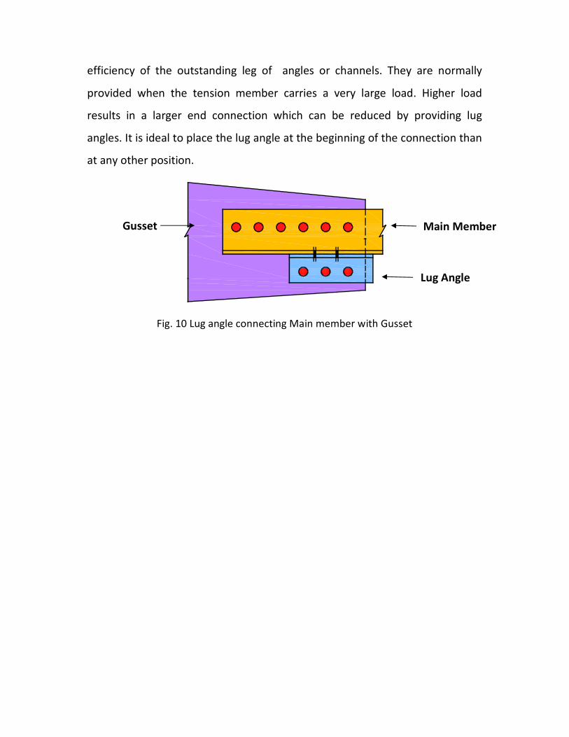
efficiency of the outstanding leg of angles or channels. They are normally
provided when the tension member carries a very large load. Higher load
results in a larger end connection which can be reduced by providing lug
angles. It is ideal to place the lug angle at the beginning of the connection than
at any other position.
Fig. 10 Lug angle connecting Main member with Gusset
Lug Angle
Main Member Gusset

8.0 Numercial Problems
Problem 1
Determine the design tensile strength of the plate 120 mm x 8 mm connected to a 12
mm thick gusset plate with bolt holes as shown in Fig. 11. The yield strength and
ultimate strength of the steel used are 250 MPa and 400 MPa. The diameter of the
bolts used is 16 mm.
30
60
30
30 60 60 30
Gusset 12 mm thick
Plate
Fig. 11 Details of end connection
Solution
The design tensile strength Td of the plate is calculated based on the following
criteria.
(i) Gross section yielding
The design strength Tdg of plate limited to the yielding of gross cross section Ag
is given by
Tdg = fy Ag /γm0
Here fy = 250 MPa, Ag = 120 x 8 = 960 mm2 and γm0 = 1.10
Hence Tdg = 218.18 kN
(ii) Net section rupture
The design strength Tdn of angle governed by rupture of net cross sectional
area, An, is given by
Tdn =0.9 fu An / γm1
Here fu = 400 MPa, γm1 = 1.25
Further, diameter of bolt hole = 16 + 2 = 18 mm
Therefore, An = (120 – 2 x18) 8 = 672 mm2. Hence, Tdn = 193.54 kN

(iii) Block shear failure
30 60 60 30
30
60
30
Fig. 12 Failure of plate in block shear
The design strength Tdg of connection shall be taken as smaller of
Tdb1 = ( Avg fy /( 3 γm0) + 0.9 Atn fu /γm1 ) , OR
Tdb2 = ( 0.9 Avn fu /( 3 γm1) + Atg fy /γm0 )
Here, Avg = (150 x 8) 2 = 2400 mm2,
Avn = [(150 – 2.5 x 18) x 8] 2 = 1680 mm2,
Atg = (60 x 8) = 480 mm2,
Atn = (60 – 1.0 x 18) x 8 = 336 mm2
Therefore, Tdb1 = 411.69 kN and Tdb2 = 388.44 kN
Hence Tdb = 388.44 kN
Design tensile strength Td
The tensile design strength Td is the least of Tdg, Tdn and Tdb
Hence, Td = Tdn = 193.54 kN

Problem 2
A single unequal angle 100 x 75 x 8 mm is connected to a 12 mm thick gusset plate at
the ends with 6 numbers of 20 mm diameter bolts to transfer tension as shown in
Fig. 13. Determine the design tensile strength of the angle if the gusset is connected
to the 100 mm leg. The yield strength and ultimate strength of the steel used are 250
MPa and 400 MPa. The diameter of the bolts used is 20 mm.
30 50 50 50 50 50 12 75
40
60100 x 75 x8
Fig. 13 Details of end connection
Solution
The design tensile strength Td of the angle is calculated based on the following
criteria.
(i) Gross section yielding
The design strength Tdg of angle limited to the yielding of gross cross section Ag
is given by
Tdg = fy Ag /γm0
Here fy = 250 MPa, Ag = (100 + 75 – 8) 8 = 1336 mm2, γm0 = 1.10
Hence Tdg = 303.64 kN
(ii) Net section rupture
The design strength Tdn of angle governed by rupture of net cross sectional area
is given by
Tdn =0.9 fu Anc / γm1 +β Ago fy /γm0
β = 1.4 – 0.076 (w/t) (fy /fu) (bs /Lc ) ≤ (fu γm0 / fy γm1)
Here fu = 400 MPa, fy = 250 MPa, γm1 = 1.25, and γm0 = 1.10
w = 75 mm, t = 8 mm, bs = (75 + 60 – 8) = 127 mm, Lc = 250 mm
Further, diameter of bolt hole = 20 + 2 = 22 mm.

Anc = (100 – 8/2 – 22) 8 = 592 mm2, Ago= (75 – 8/2) 8 = 568 mm
2
Hence, β = 1.17. Since 0.7 ≤ β ≤ 1.41 , β = 1.17
Hence, Tdn = 321.53 kN
(iii) Block shear failure
30 50 50 50 50 50
40
Fig. 14 Failure of plate in block shear
The design strength Tdg of connection shall be taken as smaller of
Tdb1 = ( Avg fy /( 3 γm0) + 0.9 Atn fu /γm1 ) , OR
Tdb2 = ( 0.9 Avn fu /( 3 γm1) + Atg fy /γm0 )
Here, Avg = 280 x 8 = 2240 mm2,
Avn = (280 – 5.5 x 22) x 8 = 1272 mm2,
Atg = 40 x 8 = 320 mm2,
Atn = (40 – 0.5 x 22) 8 = 232 mm2
Therefore, Tdb1 = 360.74 kN and Tdb2 = 284.23 kN
Hence Tdb = 284.23 kN
Design tensile strength Td
The tensile design strength Td is the least of Tdg, Tdn and Tdb
Hence, Td = Tdb = 284.23 kN

Problem 3
A tie member in a bracing system consists of two angles 75 x 75 x 6 mm bolted to a
10 mm thick gusset plate one on each side using a single row of bolts and tack
bolted. Determine the tensile capacity of the member and the number of bolts
required to develop full capacity of the member. The yield strength and ultimate
strength of the material is 250 MPa and 410 MPa, respectively.
675
75 x 75 x 6
75 Fig. 15 Details of connection at end
Solution
The design tensile strength Td of the angles is calculated based on the following
criteria.
(i) Gross section yielding
The design strength Tdg of angles limited to the yielding of gross cross section
Ag is given by
Tdg = fy Ag /γm0
Here fy = 250 MPa, Ag = 2 x 866 = 1732 mm2, γm0 = 1.10.
Hence Tdg = 393.64 kN
(ii) Net section rupture
The design strength Tdn of angle governed by rupture of net cross sectional
area. Since the number of rivets is not known, the rupture strength of net
section is approximately calculated as
Tdn = α An fu /γm1
Assuming a single line of 4 numbers 20 mm dia bolts, α = 0.8.
Dia of the bolt hole = 20 + 2 = 22mm
An = [(75 – 22 – 6/2) x 6 + (75 – 6/2) x 6] x 2 = 1464 mm2

Also, fu = 410 MPa and γm1 = 1.25
Hence, Tdn = 384.15 kN
Design of bolts
Bolts are in double shear.
Hence, strength of single 20 mm dia bolt = 2 x 45.3 = 90.6 kN
For the strength of connection to be larger than the strength of member,
Number of bolts required = 384.15 / 90.6 = 4.24
Hence provide 5 numbers of 20 mm bolts. Hence the connection is safe.
Assume edge and end distances = 35 mm and pitch = 50 mm
(iii) Block shear failure
The design strength Tdg of connection shall be taken as smaller of
Tdb1 = ( Avg fy /( 3 γm0) + 0.9 Atn fu /γm1 ) , OR
Tdb2 = ( 0.9 Avn fu /( 3 γm1) + Atg fy /γm0 )
35 50 50 50 50
35
Fig. 16 Failure of angle in block shear
Consider one angle. Here,
Avg = 235 x 6 = 1410 mm2, Avn = (235 – 4.5 x 22) x 6 = 816 mm
2,
Atg = 35 x 6 = 210 mm2, Atn = (35 –22/2) 6 = 144 mm
2
Therefore, Tdb1 = 227.50 kN and Tdb2 = 186.80 kN
Hence Tdb = 186.80 kN
Considering the two angles, the block shear strength is
Tdb = 186.80 x 2 = 373.60 kN

Tensile capacity of member Td
The tensile capacity Td is the least of Tdg, Tdn and Tdb.
Here, Tdg = 393.64 kN, Tdn = 384.15 kN and Tdb = 373.60 kN
Hence, Td = Tdb = 373.60 kN
Problem 4
Design a suitable angle section to carry a factored tensile force of 210 kN assuming a
single row of M20 bolts. The yield strength and ultimate strength of the material is
250 MPa and 410 MPa, respectively. The length of the member is 3 m.
Solution
Step 1:
Obtain the net area, An, required to carry the design load Tu from the equation
using the ultimate stress.
Tu = fu An / γm1
Here, Tu = 210 kN, fu = 410 MPa, and γm1 = 1.25
Therefore, An = 619.8 mm2
Increase the net area, An, by 25 percent to obtain the gross area.
Hence, Ag= 774.8 mm2
Step 2:
Obtain the gross area, Ag, required to carry the design load Tu from the
equation using the yield stress.
Tu = fy Ag /γm0
Here, Tu = 210 kN, fy = 250 MPa, and γm0 = 1.10
Therefore, Ag = 924.0 mm2
Step 3:
From steps 1 and 2,
Required gross area Ag,req. = 924.0 mm2 (max. value)
Select an angle 65 x 65 x 8 with Ag = 976 mm2 ( > 924.0 mm
2)

Step 4:
The strength of 20 mm diameter bolts in single shear = 45.3 kN
Hence required number of bolts = 210/45.3 = 4.64
Provide 5 bolts at a pitch of 60 mm
Step 5:
The design strength Tdg of plate limited to the yielding of gross cross section Ag
is given by
Tdg = fy Ag /γm0
Here fy = 250 MPa, Ag = 976 mm2 and γm0 = 1.10
Hence Tdg = 221.80 kN
Step 6:
The design strength Tdn of angle governed by rupture of net cross sectional
area, An, is given by
Tdn =0.9 fu Anc / γm1 +β Ago fy /γm0
β = 1.4 – 0.076 (w/t) (fy /fu) (bs /Lc ) ≤ (fu γm0 / fy γm1)
Here fu = 410 MPa, fy = 250 MPa, γm1 = 1.25, and γm0 = 1.10
w = 65 mm, t = 8 mm, bs = (65 + 35 – 8) = 92 mm,
Lc = 4 x 60 = 240 mm
Further, diameter of bolt hole = 20 + 2 = 22 mm
Anc = (65 – 8/2 – 22) 8 = 312 mm2, Ago= (65 – 8/2) 8 = 488 mm
2
Hence, β = 1.26. Since 0.7 ≤ β ≤ 1.44 , β = 1.26
Hence, Tdn = 231.85 kN
Step 7:
The design strength Tdg of connection shall be taken as smaller of
Tdb1 = ( Avg fy /( 3 γm0) + 0.9 Atn fu /γm1 ) , OR
Tdb2 = ( 0.9 Avn fu /( 3 γm1) + Atg fy /γm0 )
Assuming an edge distance of 40 mm,
Here, Avg = (40 + 60 x 4) 8 = 2240 mm2,
Avn = (40 + 60 x 4 – 4.5 x 22) 8 = 1448 mm2,
Atg = 30 x 8 = 240 mm2, Atn = (30 – 22/2) x 8 = 152 mm
2,
Therefore, Tdb1 = 338.79 kN and Tdb2 = 301.33 kN
Hence Tdb = 301.33 kN
Step 8:
The tensile capacity of member ISA 65 x 65 x 8 with 5 bolts of 20 mm diameter
is the least of Tdg, Tdn and Tdb.
Therefore, T = Tdg = 221.80 kN > 210 kN.
Hence the angle and the connection is safe.
Step 9:
Check for stiffness.
L = 3000 mm, rmin = 12.5 mm
L/ rxx = 240 < 250
Hence the section is safe.
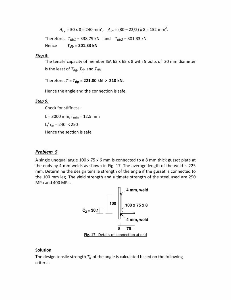
Problem 5
A single unequal angle 100 x 75 x 6 mm is connected to a 8 mm thick gusset plate at
the ends by 4 mm welds as shown in Fig. 17. The average length of the weld is 225
mm. Determine the design tensile strength of the angle if the gusset is connected to
the 100 mm leg. The yield strength and ultimate strength of the steel used are 250
MPa and 400 MPa.
8 75
C = 30.1
100 x 75 x 8100
4 mm, weld
4 mm, weld
z
Fig. 17 Details of connection at end
Solution
The design tensile strength Td of the angle is calculated based on the following
criteria.

(i) Gross section yielding
The design strength Tdg of angle limited to the yielding of gross cross section Ag
is given by
Tdg = fy Ag /γm0
Here fy = 250 MPa, Ag = 1010 mm2, γm0 = 1.10
Hence Tdg = 229.55 kN
(ii) Net section rupture
The design strength Tdn of plate governed by rupture of net cross sectional area
is given by
Tdn =0.9 fu Anc / γm1 +β Ago fy /γm0
β = 1.4 – 0.076 (w/t) (fy /fu) (bs /Lc ) ≤ (fu γm0 / fy γm1)
Here fu = 400 MPa, fy = 250 MPa, γm1 = 1.25, and γm0 = 1.10
w = 75 mm, t = 6 mm, bs = 75 mm, Lc = 225 mm
Anc = (100 – 6/2) 6= 582 mm2, Ago= (75 – 6/2) 6 = 432 mm
2
Hence, β = 1.20. Since 0.7 ≤ β ≤ 1.41 , β = 1.20
Hence, Tdn = 306.39 kN
(iii) Block shear failure
The design strength Tdg of connection shall be taken as smaller of
Tdb1 = ( Avg fy /( 3 γm0) + 0.9 Atn fu /γm1 ) , OR
Tdb2 = ( 0.9 Avn fu /( 3 γm1) + Atg fy /γm0 )
Here, Avg = (225 x 8) 2 = 3600 mm2,
Avn = Avg = 3600 mm2,
Atg = 100 x 8 = 800 mm2,
Atn = Atg = 800 mm2
Therefore, Tdb1 = 702.78 kN and Tdb2 = 780.41 kN
Hence Tdb = 702.78 kN
Design tensile strength Td
The tensile design strength Td is the least of Tdg, Tdn and Tdb.
Hence, Td = Tdg = 229.55 kN
Proportioning of weld
Tensile capacity = 229.55 kN, Capacity of 4 mm weld = 0.53 kN/mm
Hence,
Length of weld on upper side of angle = (229.55 x 30.1/100)/0.53
= 130 mm, say 140 mm
Length of weld on bottom side of angle = (229.55 x 69.9/100)/0.53
= 302.7 mm, say 310 mm
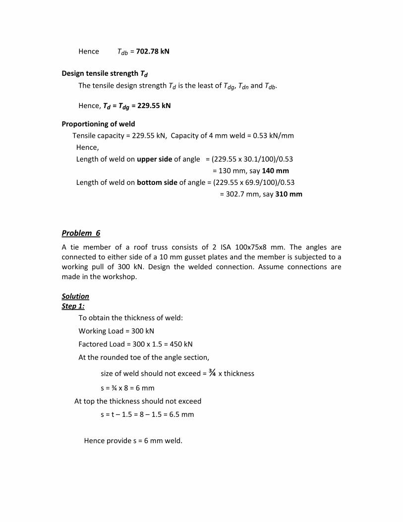
Problem 6
A tie member of a roof truss consists of 2 ISA 100x75x8 mm. The angles are
connected to either side of a 10 mm gusset plates and the member is subjected to a
working pull of 300 kN. Design the welded connection. Assume connections are
made in the workshop.
Solution
Step 1:
To obtain the thickness of weld:
Working Load = 300 kN
Factored Load = 300 x 1.5 = 450 kN
At the rounded toe of the angle section,
size of weld should not exceed = ¾ x thickness
s = ¾ x 8 = 6 mm
At top the thickness should not exceed
s = t – 1.5 = 8 – 1.5 = 6.5 mm
Hence provide s = 6 mm weld.

Step 2:
To obtain the total length of the weld required:
Each angle carries a factored pull of 450/2 = 225 kN
Let Lw be the total length of the weld required.
Assuming normal weld, t = 0.7 x 6 mm
Design strength of the weld = Lw t fu/√3 x 1/1.25
= Lw x 0.7 x 6 x 410/√3 x 1/1.25
Equating it to the factored load,
Lw x 0.7 x 6 x 410/√3 x 1/1.25 = 225 x 103
Lw = 283 mm
Step 3:
To obtain the length of top and lower weld:
Centre of gravity of the section is at a distance 31 mm from top.
Let L1 be the length of top weld and L2 be the length of lower weld.
To make centre of gravity of weld to coincide with that of angle,
L1 x31 = L2 ( 100-31)
L1 = (69/31) x L2
Required L1 + L2 = 283
L2 ((69/31) + 1) = 283
L2 = 87 mm
Hence, L1 =195 mm
Provide 6 mm weld of L1 =195 mm and L2 = 87 mm as shown in the Fig. 18
Cxx = 31 mm
ISA 10075, 8 mm
L1
L2
Cxx
Fillet at rounded end
6 mm, weld
Fig. 18 Details of weld at the end connection
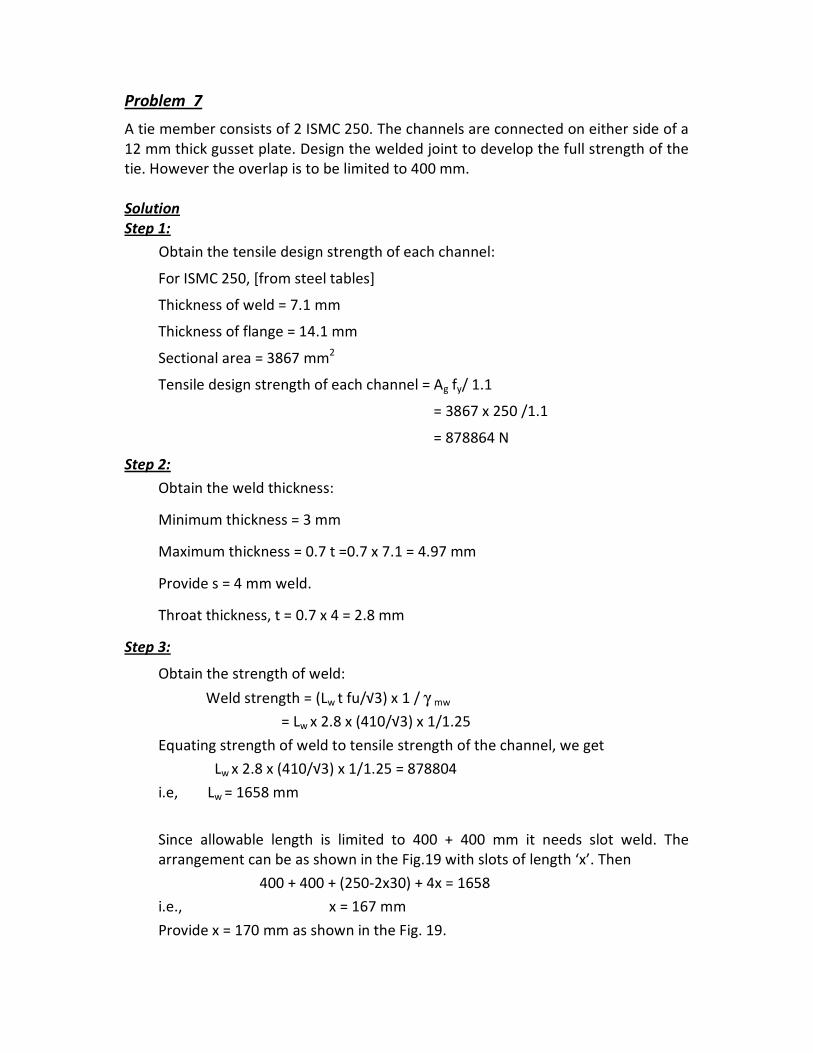
Problem 7
A tie member consists of 2 ISMC 250. The channels are connected on either side of a
12 mm thick gusset plate. Design the welded joint to develop the full strength of the
tie. However the overlap is to be limited to 400 mm.
Solution
Step 1:
Obtain the tensile design strength of each channel:
For ISMC 250, [from steel tables]
Thickness of weld = 7.1 mm
Thickness of flange = 14.1 mm
Sectional area = 3867 mm2
Tensile design strength of each channel = Ag fy/ 1.1
= 3867 x 250 /1.1
= 878864 N
Step 2:
Obtain the weld thickness:
Minimum thickness = 3 mm
Maximum thickness = 0.7 t =0.7 x 7.1 = 4.97 mm
Provide s = 4 mm weld.
Throat thickness, t = 0.7 x 4 = 2.8 mm
Step 3:
Obtain the strength of weld:
Weld strength = (Lw t fu/√3) x 1 / γ mw
= Lw x 2.8 x (410/√3) x 1/1.25
Equating strength of weld to tensile strength of the channel, we get
Lw x 2.8 x (410/√3) x 1/1.25 = 878804
i.e, Lw = 1658 mm
Since allowable length is limited to 400 + 400 mm it needs slot weld. The
arrangement can be as shown in the Fig.19 with slots of length ‘x’. Then
400 + 400 + (250-2x30) + 4x = 1658
i.e., x = 167 mm
Provide x = 170 mm as shown in the Fig. 19.

ISMC 250
30
30
60
70
60
250x
4 mm, weld
Gusset Plate
Fig. 19 Details of welding at the connection
Problem 8
A single angle member carries a factored axial force of 400 kN. Design the member
and the connection with a gusset plate and a lug angle. The yield strength and
ultimate strength of the material is 250 MPa and 410 MPa, respectively.
Solution
Sizing of Single Angle
Factored load = 400 kN
For preliminary sizing of single angle use the relation (Cl. 6.3.3 of IS 800 : 2007)
where Tdn = 500 kN, α = 0.8 ( ≥ 4 bolts), fu = 410 MPa and γm1 = 1.25
Hence, Required net area is An = 1524.4 mm2
The gross area is arrived by increasing the net area by 15% (say)
Therefore, Required gross area is Ag = 1753.1 mm2
Therefore provide ISA 125 x 75 x 10
Hence actual gross area Ag = 1902 mm2
Here, the 125 mm side is connected to the gusset and 75 mm side is the outstanding
leg.
The design strength Tdg of angle limited to the yielding of gross cross section Ag is
given by
Tdg = fy Ag /γm0
Here fy = 250 MPa, Ag = 1902 mm2, γm0 = 1.10
Hence Tdg = 432.30 kN > 400 kN O.K.

Sizing of Lug Angle
Total factored load = 400 kN
Gross area of outstanding leg in single angle = [ 75 – (10/2)] x 10
= 700 mm2
Load carried by the outstanding leg of the single angle is proportional to its area in
comparison with the total area.
Hence, load carried by outstanding leg = (700/1902) x 400 = 147.2 kN
Lug angle should be designed to take a load not less than 20% in excess of load
carried by outstanding leg (Cl. 10.12.2 of IS 800 : 2007)
Hence, Load considered for lug angle = 1.2 x 147.2 = 176.64 kN
For preliminary sizing of lug angle use the relation (Cl. 6.3.3 of IS 800 : 2007)
where Tdn = 176.64 kN, α = 0.8 ( ≥ 4 bolts), fu = 410 MPa and γm1 = 1.25
Hence, Required net area is An = 673.17 mm2
The gross area is arrived by increasing the net area by 15% (say)
Therefore, Required gross area is Ag = 774.15 mm2
Therefore provide ISA 75 x 75 x 8
Hence actual gross area Ag = 1140 mm2
Design of connections
Assume one row of 20 mm diameter bolt. Use a pitch of 2.5 x 20 = 50 mm, and an
edge distance of 30 mm (Cl. 10.2.2 and Cl. 10.2.4.2 of IS 800 : 2007)
Strength of 20 mm bolt in single shear = 45.30 kN
a) Connection of main angle member with gusset
Load carried by the connecting leg of the main member is proportional to its area in
comparison with the total area.
Gross area of connected leg = [125 – (10/2)] x 10 = 1200 mm2
Hence, load carried by connecting leg = (1200/1902) x 400 = 252.37 kN
Required number of 20 mm bolts = 252.37/45.30 = 5.57, say 6 nos.

b) Connection of lug angle with gusset
Load carried by outstanding leg = 147.2 kN
The connection should be designed to take a load not less than 20% in excess of load
carried by outstanding leg (Cl. 10.12.2 of IS 800 : 2007)
Hence load considered in the design for connection = 1.2 x 147.2
= 176.74 kN
Required number of 20 mm bolts = 176.74/45.30 = 3.89, say 5 nos.
c) Connection of main angle member with lug angle
Load carried by outstanding leg = 147.2 kN
The connection should be designed to take a load not less than 40% in excess of load
carried by outstanding leg (Cl. 10.12.2 of IS 800 : 2007)
Hence load considered in the design for connection = 1.4 x 147.2
= 206.08 kN
Required number of 20 mm bolts = 206.08/45.30 = 4.55, say 5 nos.
The details of the connection are shown in Fig. 20.
Main angle
ISA 125x75x10
Lug angle
ISA 125x75x10
Gusset
Fig. 20 Details of connection of main angle with lug angle and gusset

9.0 References
1. Subramanian, N., Design of steel structures, Oxford university press, New
Delhi, 2009.
2. Bhavikatti, S.S., Design of steel structures, I.K.I. Publishing house, New
Delhi, 2010.
3. IS 800 – 2007, Code of practice for General construction in steel, Bureau of
Indian Standards, New Delhi, 2007.