Embed Size (px)
Citation preview
© 2017 IBRACON
Volume 10, Number 4 (August 2017) p. 788 – 825 • ISSN 1983-4195http://dx.doi.org/10.1590/S1983-41952017000400002
Design of punching shear for prestressed slabs with unbonded tendons on internal columns
Dimensionamento à punção de lajes protendidas com cordoalhas engraxadas em apoios internos
Abstract
Resumo
This paper is related to the punching shear in prestressed slabs with unbonded tendons for interior columns calculated by the codes ABNT NBR 6118:2007, ABNT NBR 6118:2014, EN 1992-1-1:2004 e ACI 318-11. To calculate the punching shear resistance the formulations of the NBR 6118:07, effective until April/2014, did not consider the compression of the concrete in the plane of the slab, due to prestressing. Just the inclined components of some tendons were considered for total load applied relief, but this fact did not generate a significant difference, compared to reinforced concrete, because the inclination angle is very close to zero. The American and European provisions consider a portion related to the compression of the concrete in the plane of the slab. Differences in the results obtained by the four design codes will be exposed, showing that the EC2:04 and the NBR6118:14 achieved the best results.
Keywords: slab, punching shear, post-tensioning, codes.
Este artigo trata da punção em lajes protendidas com cordoalhas não aderentes na ligação laje-pilar interno calculada através das normas ABNT NBR 6118:2007, ABNT NBR 6118:2014, EN 1992-1-1:2004 e ACI 318-11. Para o dimensionamento à punção, as formulações da NBR 6118:2007, norma que estava vigente até abril de 2014, não levavam em conta a compressão do concreto no plano da laje devido à protensão. Apenas a com-ponente inclinada de uma parte das cordoalhas era considerada para alívio da carga solicitante de cálculo; entretanto, isso não gerava diferença significativa, com relação ao concreto armado, pelo fato de o ângulo de inclinação ser bem próximo de zero. As normas americana e europeia con-sideram uma parcela referente à compressão do concreto no plano da laje. Serão expostas, portanto, as diferenças de resultados obtidos através dos quatro códigos de dimensionamento, mostrando que o EC2:2004 e a NBR 6118:14 obtiveram os melhores resultados.
Palavras-chave: laje, punção, protensão, normas.
a Centro Tecnológico, Departamento de Engenharia Civil, Universidade Federal do Espírito Santo, Vitória, Brasil.
Received: 19 Jun 2015 • Accepted: 03 Oct 2016 • Available Online: 27 Jul 2017
L. A. R. LUCHI a
J. C. C. LEITE Jr. a
1. Introduction
1.1 Justificationandmotivation
The motivation for this article is due to the fact that the Brazilian, European and American codes have different formulations for cal-culating the punching shear in prestressed slabs, generating dif-ferent results from the same input data. In addition, the existing literature shows that the codes results in a conservative design, compared with real of tests on prestressed slabs with unbonded tendons.For punching shear design, formulations of the NBR 6118: 2007 standard that was in effect until April 2014, do not consider the con-crete compression in the slab plane, due to prestressing. Just the inclined component of some tendons was considered to relief the requesting load; however, it did not generate significant difference compared with reinforced concrete, because the inclination angle is very close to zero. The American and European standards con-sider a portion related to concrete compression in the slab plane.Thus, in order to obtain less conservative results, ABNT revised the formulation to design punching shear in the new NBR 6118: 2014 by inserting a portion related to compression in the slab plane, due to prestressing as Eurocode 2 suggests. It is known that structural designs should be safe, but it is part of the engineering function to always improve the methods of de-sign and execution to obtain more viable and economic results. Therefore, the results of this paper can show the influence of com-pressed concrete by the use of prestressing with greased tendons.
1.2 Objectives
The purpose of this article is to compare the formulations for sizing punching shear provided by NBR 6118: 2007, NBR 6118: 2014, EN 1992-1-1: 2004 and ACI 318-11. Several dimension-ing will be performed by changing load levels, sections of pillars, concrete strength and reinforcement ratio, in order to observe the difference in results between the standards, according to these variables.
2. Dimensioning standards
2.1 Brazilian standard (NBR 6118)
2.1.1 Design model
The design model corresponds to checking the shear in two or more critical surfaces. In the first critical surface (sec-tion C), the diagonal compression strength of the concrete should be checked by shear stress. In the second critical surface (section C’), at a distance of 2d of the column or concentrated load, should be verified punching shear resis-tance relating to diagonal tension. This verification should also be made for a shear stress in the C’ section. A third critical surface (section C’’), should be checked only when using shear reinforcement.
2.1.2 Internal column with symmetrical loading
For symmetrical loads:
(1)
where:
(2)
where:d is the effective height of the slab along the critical section C’.dx and dy are the effective heights in two orthogonal directions;u is the perimeter of the section C’;FSd is the factored force or concentrated reaction.
2.1.3 Verificationoftheresistantstrainofdiagonal compression of concrete
This check should be made in the section C, for slabs with or with-out punching shear reinforcement.
(3)where:av=(1-fck/250), fck in megapascals.The value of τRd2 may be increased by 20% for multi-axial states of stress to internal columns when the adjacent spans do not differ more than 50% and if there are no openings near the column.
2.1.4 Resistant strain in the critical surface C’ in structural elements without punching shear reinforcement
The resistant strain in the critical surface C’ must be calculated, according to NBR 6118:2014, as follows:
(4)where:
(5)
(6)where:d is the effective height of the slab along the critical section C’ of the force application area, in centimeters;ρ is the geometric ratio of flexural reinforcement;ρx and ρy are reinforcement ratios in two orthogonal directions;scp is the average compression strain in the slab plane.NBR 6118:2007 considered the τRd1 calculated according to the equation:
(7)
Therefore, ignoring the compression in the slab plane.
789IBRACON Structures and Materials Journal • 2017 • vol. 10 • nº 4
L. A. R. LUCHI | J. C. C. LEITE Jr.
790 IBRACON Structures and Materials Journal • 2017 • vol. 10 • nº 4
Design of punching shear for prestressed slabs with unbonded tendons on internal columns
2.1.5 Resistant strain in the critical surface C’ in structural elements with punching shear reinforcement
The resistant strain in the critical surface C’ must be calculated, according to NBR 6118:2014, as follows:
(8)
where:
(9)where:sr is the radial spacing between the reinforcement punching shear lines, not more than 0,75d;Asw is the area of punching shear reinforcement in a full section parallel to C’;a is the inclination angle between the axis of the punching shear reinforcement and the plane of the slab;u is the critical perimeter;fywd is the factored resistance of the punching shear reinforcement, not greater than 300MPa to connectors or 250MPa to stirrups (CA-50/60). For slabs with thickness greater than 15cm, these values can be increased from linear interpolation.NBR 6118:2007 considered the τRd3 calculated according to the equation:
(10)
Therefore, ignoring the compression in the slab plane
2.1.6 DefinitionofthecriticalsurfaceC’’
When it is necessary to use punching shear reinforcement, it must be extended in parallel sections to C’ until an outline C’’, away 2d from the last section, when reinforcement is no longer necessary (τSd ≤ τRd1).
2.1.7 Verificationofprestressedstructuralelements
The check should be made as follows:
(11)where:
(12)where:τPd is the stress due to the effect of inclined prestressing cables crossing the section considered in a perimeter away d/2 from the column face.
Pkinf,i is the prestressing force un the cable i;α is the inclination angle of the cable i relative to slab plane;u is the critical perimeter of the considered section, in which are calculated τSd,ef and τSd.
2.2 American standard (ACI 318)
2.2.1 Control perimeters
The American standard recommends the analysis of stresses in criti-cal sections located at a distance of d/2 (d is the useful height of the slab), from the face of the columns or concentrated loads. The perim-eter of these sections is called effective perimeter b0. After determin-ing that perimeter, the resistant strain and actuating strain are com-pared. If necessary, the slab thickness may be increased or punching shear reinforcement can be added to increase the resistant strain.
2.2.2 Calculation of actuating strain τuintheaffective perimeter bo
The shear stress actuating on the slab-internal column connection for centered loads, is given by:
(13)where:Fu is the factored shear force;Ac is the concrete area of the effective critical section.
2.2.3 Calculation of resistant strain τuintheaffective perimeter bo
• Resistant strain of slab without punching shear reinforcement:
(14)
τc is the strain related to the concrete, taken as the smallest of the two following values:
(15)
(16)where:f’c is the specified compression strengh of concrete, in MPa;b0 is the critical section for shear in slabs;β is the ratio between the largest and the smallest side of the col-umn;d is the effective height of the slab;aS is equal to 40 for internal columns.• Resistant strain of slab with punching shear reinforcement:
(17)(18)
791IBRACON Structures and Materials Journal • 2017 • vol. 10 • nº 4
L. A. R. LUCHI | J. C. C. LEITE Jr.
where:τc is the strain related to the concrete;τs is the strain related do the reinforcement steel:
(19)where:Av is the area of the slab shear reinforcement;fyt is the yield stress of the punching shear reinforcement steel, in MPa, less than or equal to 400MPa;bo is the critical section for shear;a is the inclination angle between the axis of the punching shear reinforcement and the plane of the slab;s is the reinforcement spacing, in millimeters.The punching shear reinforcement must be extended on parallel contours to the edge of the column faces, until a distance equal to d/2 of the last line of reinforcement, the shear stress applied is not larger than 0,17 'cf .
2.2.4 Verificationforprestressedstructuralelements
For prestressed slabs, the shear strength of the concrete can be calculated from the following formulation:
(20)
where:f’c is the specified compression strengh of concrete; bp is the lowest value between 0,29 and 0,083
s
o
α d1,5
b
æ ö+ç ÷
è ø;
d is the effective height of the slab;bo is the critical section for shear;as is equal to 40 for internal columns;fpc is the average compression strength of the concrete in both or-thogonal directions due to prestressing;VP is the vertical component of prestressing forces located within the critical section.It should also take into consideration:n any part of the cross section of the column can not be more than
four times the height of the slab next to a discontinuous edge;n f’c value can not be greater than 33,64MPa;n in each direction, fpc can not be less than 0,9MPa or greater
than 3,5MPa.
2.3 European standard (EC2)
The European Standard recommends that punching shear analysis must be first made on the perimeter of the face (perimeter uo) and then in a perimeter away the 2d of the face or concentrated load (perimeter u1). If the shear reinforcement is needed, another contour must be checked out of the last line of reinforcement, called perimeter u2.
2.3.1 Calculation of applicants strains in control perimeters
(21)
where: FEd is the factored shear force;d is the effective height of the slab;ui is the considered control perimeter;b is the factor corresponding to bending moment.
2.3.2 Calculation of resistant strains in control perimeters
In the control perimeter uo:
(22)where:ν = 0,6 (1-fck/250);fcd is the fatored compression strengh of concrete (MPa).• In the control perimeter u1:a) For elements without punching shear reinforcement:
( ) ( )
11 323 2
, 10,12 100 0, 035 ( )Ed Rd c ck ckk f k ft t r£ = ³ (23)where:
(24)
r1 is the calculated average ratio of reinforcement considering the width of the column adding 3d for each face.fck in MPa and d in millimeters.b) For elements with punching shear reinforcement:
, , , 10,75 1,5( / ) [1/( )] Ed Rd cs Rd c r sw ywd efd s A f u d sent t t a£ = + (25)
where:Asw is the punching shear reinforcement area in the perimeter con-sidered (mm²);sr is the radial spacing between the reinforcement punching shear lines (mm);fywd,ef is the effective resistance of the reinforcement(fywd,ef = 250 + 0,25d ≤ fywd in MPa);d is the effective average thickness of the slabs, in both directions (mm);a is the angle between the shear reinforcement and the slab plane.
2.3.3 Verificationforprestressedslabs
In the case of prestressed slabs, the concrete strength can be set by the expression:
(26)where:scp is the average compression strain in the slab plane.The vertical component Vp, resulting from the inclined cables that pass through the perimeter u1, can be considered as relief of shear load.
(27)where:nx and ny is the number of cables that cross the control section in each direction;
792 IBRACON Structures and Materials Journal • 2017 • vol. 10 • nº 4
Design of punching shear for prestressed slabs with unbonded tendons on internal columns
Pp is the average prestressing force (at rupture);ax and ay are the inclination angles of the cables in the boundary of control sections.
3. Comparativedesignsandresults
3.1 Considerations
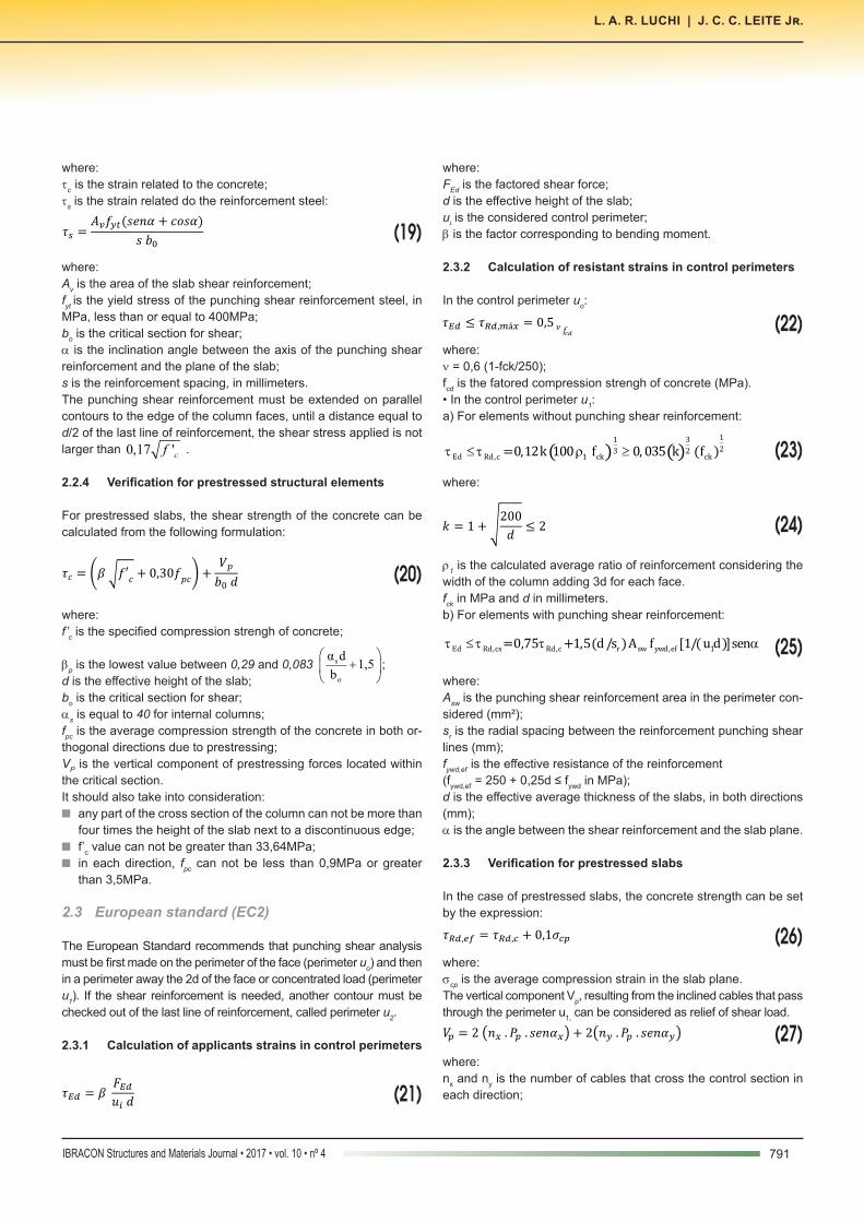
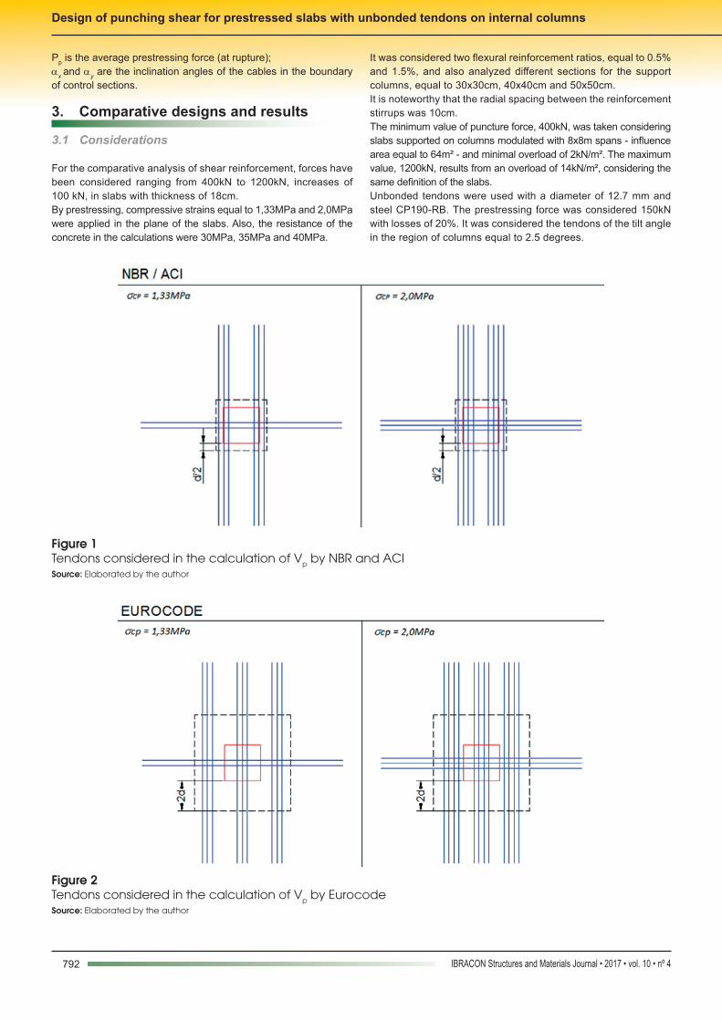
For the comparative analysis of shear reinforcement, forces have been considered ranging from 400kN to 1200kN, increases of 100 kN, in slabs with thickness of 18cm.By prestressing, compressive strains equal to 1,33MPa and 2,0MPa were applied in the plane of the slabs. Also, the resistance of the concrete in the calculations were 30MPa, 35MPa and 40MPa.
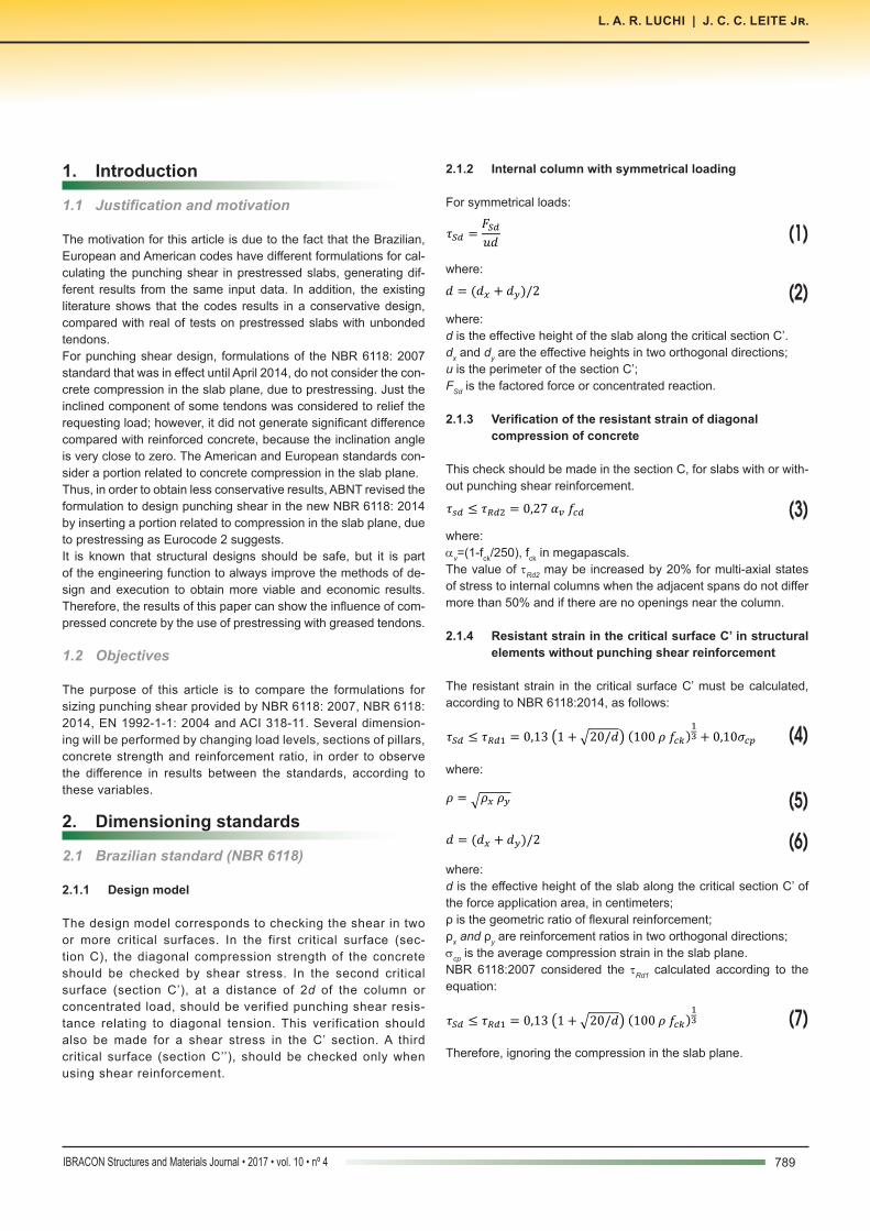
It was considered two flexural reinforcement ratios, equal to 0.5% and 1.5%, and also analyzed different sections for the support columns, equal to 30x30cm, 40x40cm and 50x50cm.It is noteworthy that the radial spacing between the reinforcement stirrups was 10cm.The minimum value of puncture force, 400kN, was taken considering slabs supported on columns modulated with 8x8m spans - influence area equal to 64m² - and minimal overload of 2kN/m². The maximum value, 1200kN, results from an overload of 14kN/m², considering the same definition of the slabs.Unbonded tendons were used with a diameter of 12.7 mm and steel CP190-RB. The prestressing force was considered 150kN with losses of 20%. It was considered the tendons of the tilt angle in the region of columns equal to 2.5 degrees.
Figure 1Tendons considered in the calculation of Vp by NBR and ACI Source: Elaborated by the author
Figure 2Tendons considered in the calculation of Vp by EurocodeSource: Elaborated by the author
793IBRACON Structures and Materials Journal • 2017 • vol. 10 • nº 4
L. A. R. LUCHI | J. C. C. LEITE Jr.
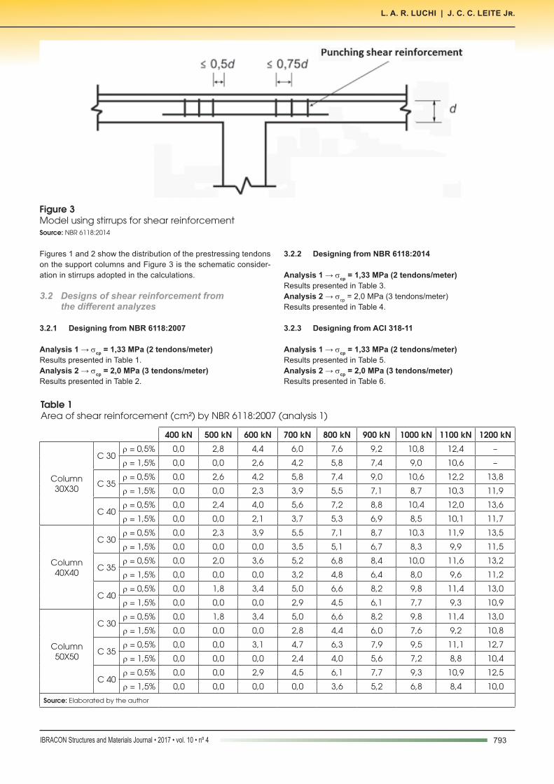
Figures 1 and 2 show the distribution of the prestressing tendons on the support columns and Figure 3 is the schematic consider-ation in stirrups adopted in the calculations.
3.2 Designs of shear reinforcement from thedifferentanalyzes
3.2.1 Designing from NBR 6118:2007
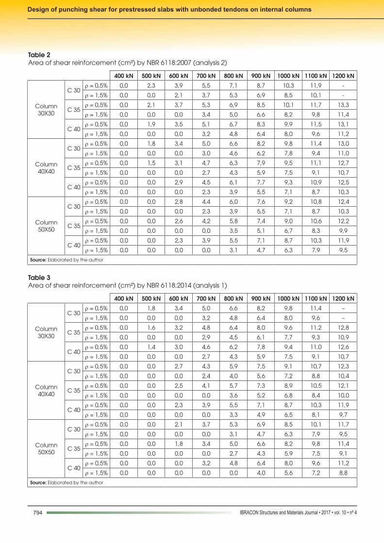
Analysis1→scp = 1,33 MPa (2 tendons/meter) Results presented in Table 1.Analysis2→scp = 2,0 MPa (3 tendons/meter)Results presented in Table 2.
3.2.2 Designing from NBR 6118:2014
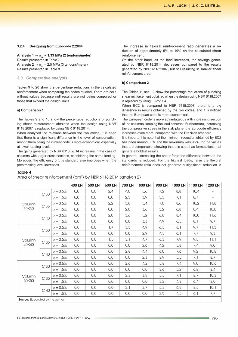
Analysis1→scp = 1,33 MPa (2 tendons/meter) Results presented in Table 3.Analysis 2 → scp = 2,0 MPa (3 tendons/meter)Results presented in Table 4.
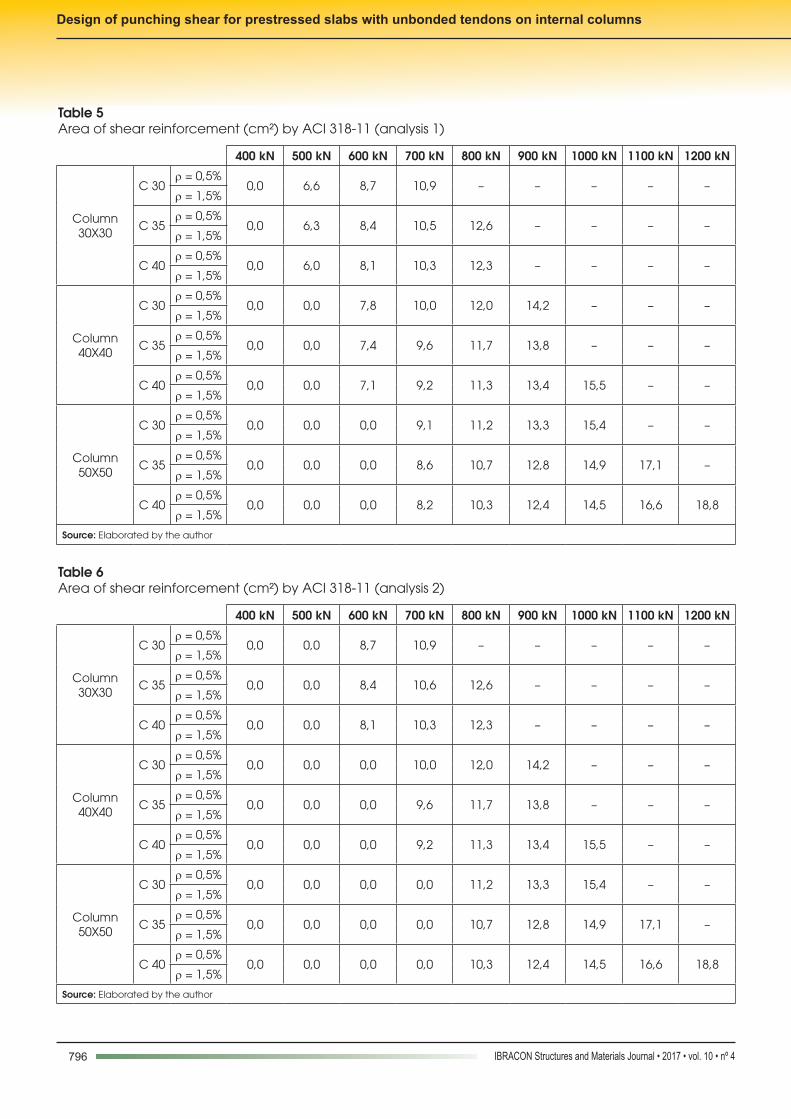
3.2.3 Designing from ACI 318-11
Analysis1→scp = 1,33 MPa (2 tendons/meter) Results presented in Table 5.Analysis2→scp = 2,0 MPa (3 tendons/meter)Results presented in Table 6.
Table 1Area of shear reinforcement (cm²) by NBR 6118:2007 (analysis 1)
400 kN 500 kN 600 kN 700 kN 800 kN 900 kN 1000 kN 1100 kN 1200 kN
Column 30X30
C 30r = 0,5% 0,0 2,8 4,4 6,0 7,6 9,2 10,8 12,4 –
r = 1,5% 0,0 0,0 2,6 4,2 5,8 7,4 9,0 10,6 –
C 35r = 0,5% 0,0 2,6 4,2 5,8 7,4 9,0 10,6 12,2 13,8
r = 1,5% 0,0 0,0 2,3 3,9 5,5 7,1 8,7 10,3 11,9
C 40r = 0,5% 0,0 2,4 4,0 5,6 7,2 8,8 10,4 12,0 13,6
r = 1,5% 0,0 0,0 2,1 3,7 5,3 6,9 8,5 10,1 11,7
Column 40X40
C 30r = 0,5% 0,0 2,3 3,9 5,5 7,1 8,7 10,3 11,9 13,5
r = 1,5% 0,0 0,0 0,0 3,5 5,1 6,7 8,3 9,9 11,5
C 35r = 0,5% 0,0 2,0 3,6 5,2 6,8 8,4 10,0 11,6 13,2
r = 1,5% 0,0 0,0 0,0 3,2 4,8 6,4 8,0 9,6 11,2
C 40r = 0,5% 0,0 1,8 3,4 5,0 6,6 8,2 9,8 11,4 13,0
r = 1,5% 0,0 0,0 0,0 2,9 4,5 6,1 7,7 9,3 10,9
Column 50X50
C 30r = 0,5% 0,0 1,8 3,4 5,0 6,6 8,2 9,8 11,4 13,0
r = 1,5% 0,0 0,0 0,0 2,8 4,4 6,0 7,6 9,2 10,8
C 35r = 0,5% 0,0 0,0 3,1 4,7 6,3 7,9 9,5 11,1 12,7
r = 1,5% 0,0 0,0 0,0 2,4 4,0 5,6 7,2 8,8 10,4
C 40r = 0,5% 0,0 0,0 2,9 4,5 6,1 7,7 9,3 10,9 12,5
r = 1,5% 0,0 0,0 0,0 0,0 3,6 5,2 6,8 8,4 10,0
Source: Elaborated by the author
Figure 3Model using stirrups for shear reinforcementSource: NBR 6118:2014
794 IBRACON Structures and Materials Journal • 2017 • vol. 10 • nº 4
Design of punching shear for prestressed slabs with unbonded tendons on internal columns
Table 3Area of shear reinforcement (cm²) by NBR 6118:2014 (analysis 1)
400 kN 500 kN 600 kN 700 kN 800 kN 900 kN 1000 kN 1100 kN 1200 kN
Column 30X30
C 30r = 0,5% 0,0 1,8 3,4 5,0 6,6 8,2 9,8 11,4 –
r = 1,5% 0,0 0,0 0,0 3,2 4,8 6,4 8,0 9,6 –
C 35r = 0,5% 0,0 1,6 3,2 4,8 6,4 8,0 9,6 11,2 12,8
r = 1,5% 0,0 0,0 0,0 2,9 4,5 6,1 7,7 9,3 10,9
C 40r = 0,5% 0,0 1,4 3,0 4,6 6,2 7,8 9,4 11,0 12,6
r = 1,5% 0,0 0,0 0,0 2,7 4,3 5,9 7,5 9,1 10,7
Column 40X40
C 30r = 0,5% 0,0 0,0 2,7 4,3 5,9 7,5 9,1 10,7 12,3
r = 1,5% 0,0 0,0 0,0 2,4 4,0 5,6 7,2 8,8 10,4
C 35r = 0,5% 0,0 0,0 2,5 4,1 5,7 7,3 8,9 10,5 12,1
r = 1,5% 0,0 0,0 0,0 0,0 3,6 5,2 6,8 8,4 10,0
C 40r = 0,5% 0,0 0,0 2,3 3,9 5,5 7,1 8,7 10,3 11,9
r = 1,5% 0,0 0,0 0,0 0,0 3,3 4,9 6,5 8,1 9,7
Column 50X50
C 30r = 0,5% 0,0 0,0 2,1 3,7 5,3 6,9 8,5 10,1 11,7
r = 1,5% 0,0 0,0 0,0 0,0 3,1 4,7 6,3 7,9 9,5
C 35r = 0,5% 0,0 0,0 1,8 3,4 5,0 6,6 8,2 9,8 11,4
r = 1,5% 0,0 0,0 0,0 0,0 2,7 4,3 5,9 7,5 9,1
C 40r = 0,5% 0,0 0,0 0,0 3,2 4,8 6,4 8,0 9,6 11,2
r = 1,5% 0,0 0,0 0,0 0,0 0,0 4,0 5,6 7,2 8,8
Source: Elaborated by the author
Table 2Area of shear reinforcement (cm²) by NBR 6118:2007 (analysis 2)
400 kN 500 kN 600 kN 700 kN 800 kN 900 kN 1000 kN 1100 kN 1200 kN
Column 30X30
C 30r = 0,5% 0,0 2,3 3,9 5,5 7,1 8,7 10,3 11,9 -
r = 1,5% 0,0 0,0 2,1 3,7 5,3 6,9 8,5 10,1 -
C 35r = 0,5% 0,0 2,1 3,7 5,3 6,9 8,5 10,1 11,7 13,3
r = 1,5% 0,0 0,0 0,0 3,4 5,0 6,6 8,2 9,8 11,4
C 40r = 0,5% 0,0 1,9 3,5 5,1 6,7 8,3 9,9 11,5 13,1
r = 1,5% 0,0 0,0 0,0 3,2 4,8 6,4 8,0 9,6 11,2
Column 40X40
C 30r = 0,5% 0,0 1,8 3,4 5,0 6,6 8,2 9,8 11,4 13,0
r = 1,5% 0,0 0,0 0,0 3,0 4,6 6,2 7,8 9,4 11,0
C 35r = 0,5% 0,0 1,5 3,1 4,7 6,3 7,9 9,5 11,1 12,7
r = 1,5% 0,0 0,0 0,0 2,7 4,3 5,9 7,5 9,1 10,7
C 40r = 0,5% 0,0 0,0 2,9 4,5 6,1 7,7 9,3 10,9 12,5
r = 1,5% 0,0 0,0 0,0 2,3 3,9 5,5 7,1 8,7 10,3
Column 50X50
C 30r = 0,5% 0,0 0,0 2,8 4,4 6,0 7,6 9,2 10,8 12,4
r = 1,5% 0,0 0,0 0,0 2,3 3,9 5,5 7,1 8,7 10,3
C 35r = 0,5% 0,0 0,0 2,6 4,2 5,8 7,4 9,0 10,6 12,2
r = 1,5% 0,0 0,0 0,0 0,0 3,5 5,1 6,7 8,3 9,9
C 40r = 0,5% 0,0 0,0 2,3 3,9 5,5 7,1 8,7 10,3 11,9
r = 1,5% 0,0 0,0 0,0 0,0 3,1 4,7 6,3 7,9 9,5
Source: Elaborated by the author
795IBRACON Structures and Materials Journal • 2017 • vol. 10 • nº 4
L. A. R. LUCHI | J. C. C. LEITE Jr.
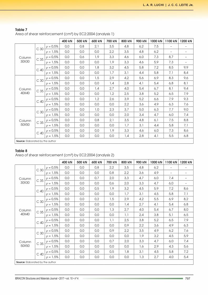
3.2.4 Designing from Eurocode 2:2004
Analysis1→scp = 1,33 MPa (2 tendons/meter) Results presented in Table 7.Analysis 2 → scp = 2,0 MPa (3 tendons/meter)Results presented in Table 8.
3.3 Comparative analysis
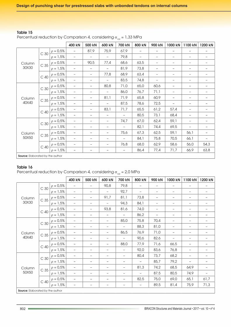
Tables 9 to 20 show the percentage reductions in the calculated reinforcement when comparing the codes studied. There are cells without values because null results are not being compared or those that exceed the design limits.
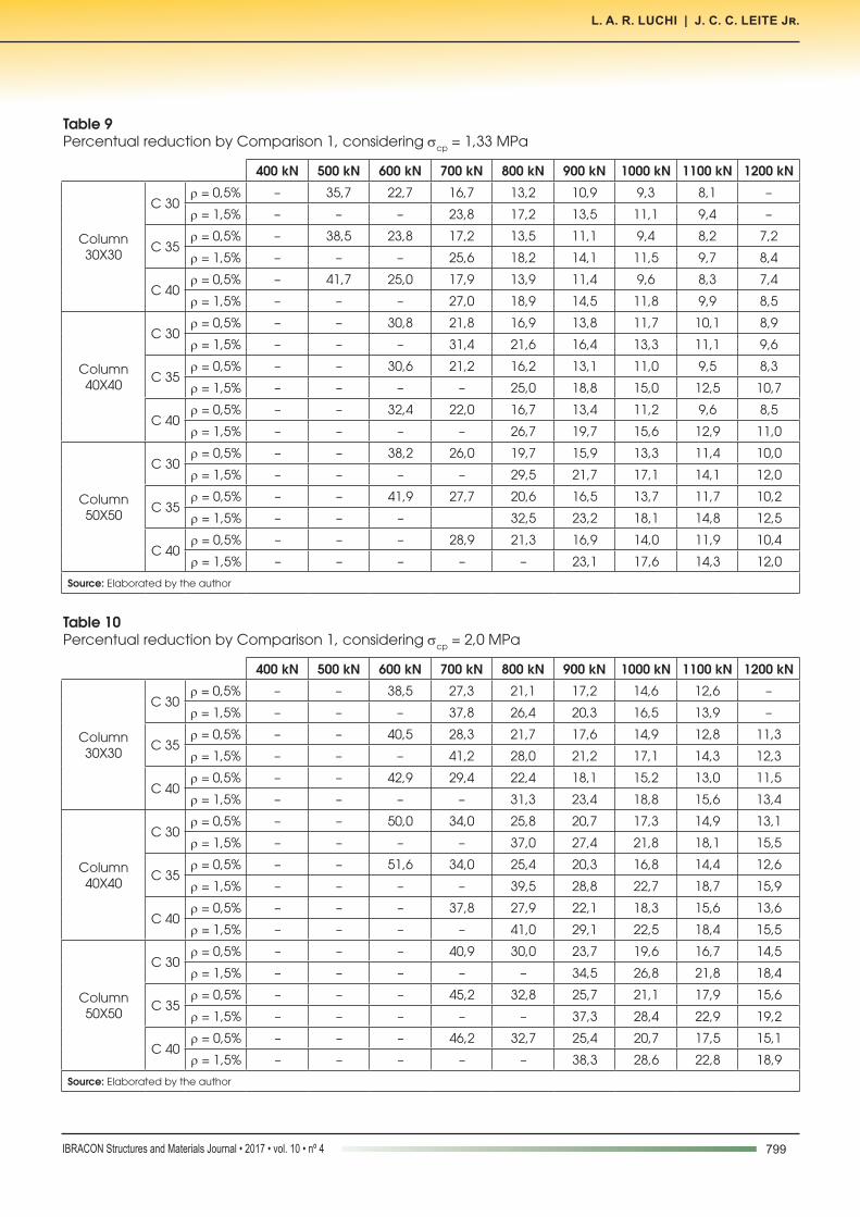
a) Comparison 1
The Tables 9 and 10 show the percentage reductions of punch-ing shear reinforcement obtained when the design using NBR 6118:2007 is replaced by using NBR 6118:2014.When analyzed the relations between the two codes, it is seen that there is a significant difference in the level of conservatism among them being the current code is more economical, especially at lower loading levels. The gains generated by NBR 6118: 2014 increases in the case of columns with larger cross sections, considering the same loading. Moreover, the efficiency of this standard also improves when the prestressing level increases.
The increase in flexural reinforcement ratio generates a re-duction of approximately 5% to 10% on the calculated shear reinforcement.On the other hand, as the load increases, the savings gener-ated by NBR 6118:2014 decreases compared to the results generated by NBR 6118:2007, but still resulting in smaller shear reinforcement area.
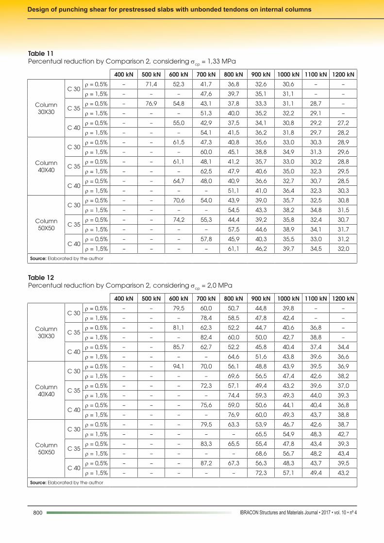
b) Comparison 2
The Tables 11 and 12 show the percentage reductions of punching shear reinforcement obtained when the design using NBR 6118:2007 is replaced by using EC2:2004.When EC2 is compared to NBR 6118:2007, there is a big difference in results obtained by the two codes, and it is noticed that the European code is more economical. The European code is more advantageous with increasing section of the columns, keeping the load constant. Furthermore, increasing the compressive stress in the slab plane, the Eurocode efficiency increases even more, compared with the Brazilian standard.It is important to note that the minimum reduction obtained by EC2 has been around 30% and the maximum was 95%, for the values that are comparable, showing that this code has formulations that generate boldest results. In general, increasing the shear force the difference between the standards is reduced. For the highest loads, raise the flexural reinforcement ratio does not generate a significant reduction in
Table 4Area of shear reinforcement (cm²) by NBR 6118:2014 (analysis 2)
400 kN 500 kN 600 kN 700 kN 800 kN 900 kN 1000 kN 1100 kN 1200 kN
Column 30X30
C 30r = 0,5% 0,0 0,0 2,4 4,0 5,6 7,2 8,8 10,4 –
r = 1,5% 0,0 0,0 0,0 2,3 3,9 5,5 7,1 8,7 –
C 35r = 0,5% 0,0 0,0 2,2 3,8 5,4 7,0 8,6 10,2 11,8
r = 1,5% 0,0 0,0 0,0 2,0 3,6 5,2 6,8 8,4 10,0
C 40r = 0,5% 0,0 0,0 2,0 3,6 5,2 6,8 8,4 10,0 11,6
r = 1,5% 0,0 0,0 0,0 0,0 3,3 4,9 6,5 8,1 9,7
Column 40X40
C 30r = 0,5% 0,0 0,0 1,7 3,3 4,9 6,5 8,1 9,7 11,3
r = 1,5% 0,0 0,0 0,0 0,0 2,9 4,5 6,1 7,7 9,3
C 35r = 0,5% 0,0 0,0 1,5 3,1 4,7 6,3 7,9 9,5 11,1
r = 1,5% 0,0 0,0 0,0 0,0 2,6 4,2 5,8 7,4 9,0
C 40r = 0,5% 0,0 0,0 0,0 2,8 4,4 6,0 7,6 9,2 10,8
r = 1,5% 0,0 0,0 0,0 0,0 2,3 3,9 5,5 7,1 8,7
Column 50X50
C 30r = 0,5% 0,0 0,0 0,0 2,6 4,2 5,8 7,4 9,0 10,6
r = 1,5% 0,0 0,0 0,0 0,0 0,0 3,6 5,2 6,8 8,4
C 35r = 0,5% 0,0 0,0 0,0 2,3 3,9 5,5 7,1 8,7 10,3
r = 1,5% 0,0 0,0 0,0 0,0 0,0 3,2 4,8 6,4 8,0
C 40r = 0,5% 0,0 0,0 0,0 2,1 3,7 5,3 6,9 8,5 10,1
r = 1,5% 0,0 0,0 0,0 0,0 0,0 2,9 4,5 6,1 7,7
Source: Elaborated by the author
796 IBRACON Structures and Materials Journal • 2017 • vol. 10 • nº 4
Design of punching shear for prestressed slabs with unbonded tendons on internal columns
Table 5Area of shear reinforcement (cm²) by ACI 318-11 (analysis 1)
400 kN 500 kN 600 kN 700 kN 800 kN 900 kN 1000 kN 1100 kN 1200 kN
Column 30X30
C 30r = 0,5%
0,0 6,6 8,7 10,9 – – – – –r = 1,5%
C 35r = 0,5%
0,0 6,3 8,4 10,5 12,6 – – – –r = 1,5%
C 40r = 0,5%
0,0 6,0 8,1 10,3 12,3 – – – –r = 1,5%
Column 40X40
C 30r = 0,5%
0,0 0,0 7,8 10,0 12,0 14,2 – – –r = 1,5%
C 35r = 0,5%
0,0 0,0 7,4 9,6 11,7 13,8 – – –r = 1,5%
C 40r = 0,5%
0,0 0,0 7,1 9,2 11,3 13,4 15,5 – –r = 1,5%
Column 50X50
C 30r = 0,5%
0,0 0,0 0,0 9,1 11,2 13,3 15,4 – –r = 1,5%
C 35r = 0,5%
0,0 0,0 0,0 8,6 10,7 12,8 14,9 17,1 –r = 1,5%
C 40r = 0,5%
0,0 0,0 0,0 8,2 10,3 12,4 14,5 16,6 18,8r = 1,5%
Source: Elaborated by the author
Table 6Area of shear reinforcement (cm²) by ACI 318-11 (analysis 2)
400 kN 500 kN 600 kN 700 kN 800 kN 900 kN 1000 kN 1100 kN 1200 kN
Column 30X30
C 30r = 0,5%
0,0 0,0 8,7 10,9 – – – – –r = 1,5%
C 35r = 0,5%
0,0 0,0 8,4 10,6 12,6 – – – –r = 1,5%
C 40r = 0,5%
0,0 0,0 8,1 10,3 12,3 – – – –r = 1,5%
Column 40X40
C 30r = 0,5%
0,0 0,0 0,0 10,0 12,0 14,2 – – –r = 1,5%
C 35r = 0,5%
0,0 0,0 0,0 9,6 11,7 13,8 – – –r = 1,5%
C 40r = 0,5%
0,0 0,0 0,0 9,2 11,3 13,4 15,5 – –r = 1,5%
Column 50X50
C 30r = 0,5%
0,0 0,0 0,0 0,0 11,2 13,3 15,4 – –r = 1,5%
C 35r = 0,5%
0,0 0,0 0,0 0,0 10,7 12,8 14,9 17,1 –r = 1,5%
C 40r = 0,5%
0,0 0,0 0,0 0,0 10,3 12,4 14,5 16,6 18,8r = 1,5%
Source: Elaborated by the author
797IBRACON Structures and Materials Journal • 2017 • vol. 10 • nº 4
L. A. R. LUCHI | J. C. C. LEITE Jr.
Table 7Area of shear reinforcement (cm²) by EC2:2004 (analysis 1)
400 kN 500 kN 600 kN 700 kN 800 kN 900 kN 1000 kN 1100 kN 1200 kN
Column 30X30
C 30r = 0,5% 0,0 0,8 2,1 3,5 4,8 6,2 7,5 – –
r = 1,5% 0,0 0,0 0,0 2,2 3,5 4,8 6,2 – –
C 35r = 0,5% 0,0 0,6 1,9 3,3 4,6 6,0 7,3 8,7 –
r = 1,5% 0,0 0,0 0,0 1,9 3,3 4,6 5,9 7,3 –
C 40r = 0,5% 0,0 0,0 1,8 3,2 4,5 5,8 7,2 8,5 9,9
r = 1,5% 0,0 0,0 0,0 1,7 3,1 4,4 5,8 7,1 8,4
Column 40X40
C 30r = 0,5% 0,0 0,0 1,5 2,9 4,2 5,6 6,9 8,3 9,6
r = 1,5% 0,0 0,0 0,0 1,4 2,8 4,1 5,4 6,8 8,1
C 35r = 0,5% 0,0 0,0 1,4 2,7 4,0 5,4 6,7 8,1 9,4
r = 1,5% 0,0 0,0 0,0 1,2 2,5 3,8 5,2 6,5 7,9
C 40r = 0,5% 0,0 0,0 1,2 2,6 3,9 5,2 6,6 7,9 9,3
r = 1,5% 0,0 0,0 0,0 0,0 2,2 3,6 4,9 6,3 7,6
Column 50X50
C 30r = 0,5% 0,0 0,0 1,0 2,3 3,7 5,0 6,3 7,7 9,0
r = 1,5% 0,0 0,0 0,0 0,0 2,0 3,4 4,7 6,0 7,4
C 35r = 0,5% 0,0 0,0 0,8 2,1 3,5 4,8 6,1 7,5 8,8
r = 1,5% 0,0 0,0 0,0 0,0 1,7 3,1 4,4 5,8 7,1
C 40r = 0,5% 0,0 0,0 0,0 1,9 3,3 4,6 6,0 7,3 8,6
r = 1,5% 0,0 0,0 0,0 0,0 1,4 2,8 4,1 5,5 6,8
Source: Elaborated by the author
Table 8Area of shear reinforcement (cm²) by EC2:2004 (analysis 2)
400 kN 500 kN 600 kN 700 kN 800 kN 900 kN 1000 kN 1100 kN 1200 kN
Column 30X30
C 30r = 0,5% 0,0 0,0 0,8 2,2 3,5 4,8 6,2 – –
r = 1,5% 0,0 0,0 0,0 0,8 2,2 3,6 4,9 – –
C 35r = 0,5% 0,0 0,0 0,7 2,0 3,3 4,7 6,0 7,4 –
r = 1,5% 0,0 0,0 0,0 0,6 2,0 3,3 4,7 6,0 –
C 40r = 0,5% 0,0 0,0 0,5 1,9 3,2 4,5 5,9 7,2 8,6
r = 1,5% 0,0 0,0 0,0 0,0 1,7 3,1 4,5 5,8 7,1
Column 40X40
C 30r = 0,5% 0,0 0,0 0,2 1,5 2,9 4,2 5,5 6,9 8,2
r = 1,5% 0,0 0,0 0,0 0,0 1,4 2,7 4,1 5,4 6,8
C 35r = 0,5% 0,0 0,0 0,0 1,3 2,7 4,0 5,4 6,7 8,0
r = 1,5% 0,0 0,0 0,0 0,0 1,1 2,4 3,8 5,1 6,5
C 40r = 0,5% 0,0 0,0 0,0 1,1 2,5 3,8 5,2 6,5 7,9
r = 1,5% 0,0 0,0 0,0 0,0 0,9 2,2 3,6 4,9 6,3
Column 50X50
C 30r = 0,5% 0,0 0,0 0,0 0,9 2,2 3,5 4,9 6,2 7,6
r = 1,5% 0,0 0,0 0,0 0,0 0,0 1,9 3,2 4,5 5,9
C 35r = 0,5% 0,0 0,0 0,0 0,7 2,0 3,3 4,7 6,0 7,4
r = 1,5% 0,0 0,0 0,0 0,0 0,0 1,6 2,9 4,3 5,6
C 40r = 0,5% 0,0 0,0 0,0 0,5 1,8 3,1 4,5 5,8 7,2
r = 1,5% 0,0 0,0 0,0 0,0 0,0 1,3 2,7 4,0 5,4
Source: Elaborated by the author
798 IBRACON Structures and Materials Journal • 2017 • vol. 10 • nº 4
Design of punching shear for prestressed slabs with unbonded tendons on internal columns
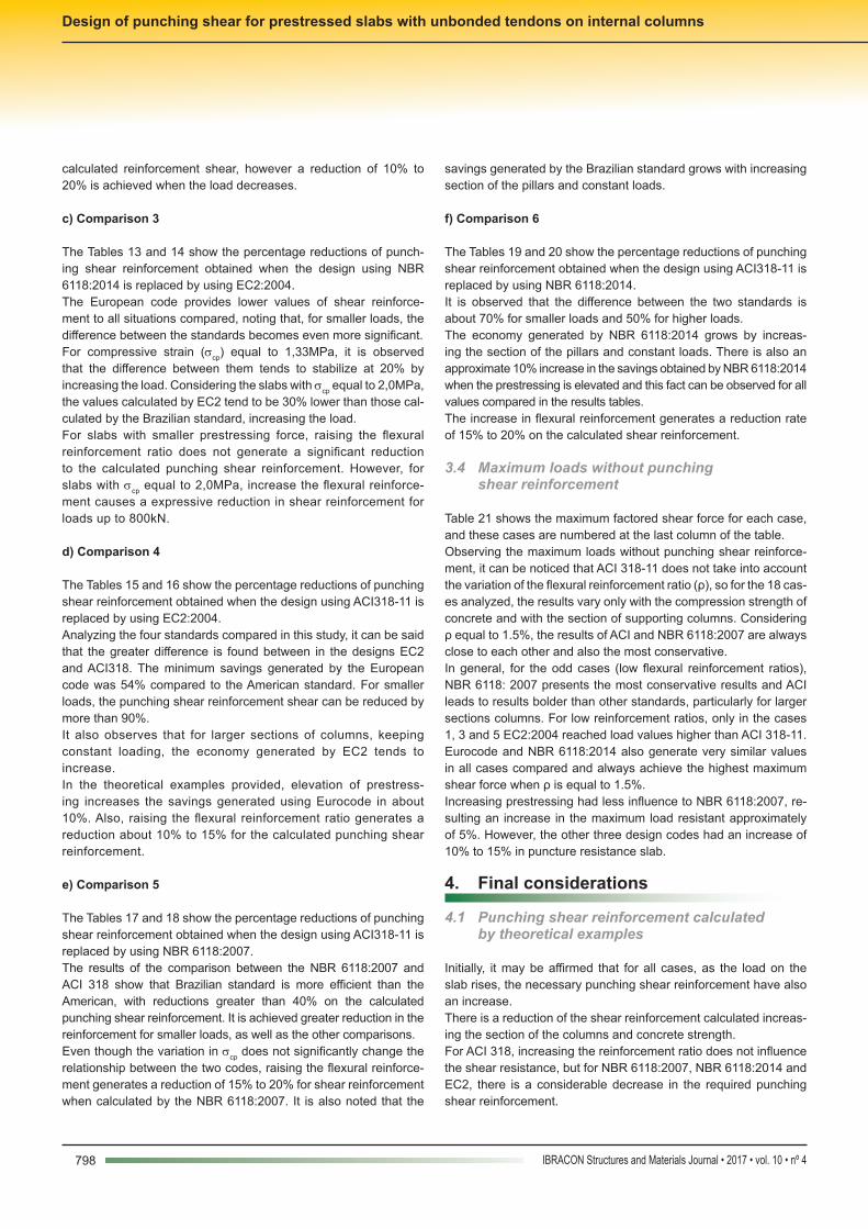
calculated reinforcement shear, however a reduction of 10% to 20% is achieved when the load decreases.
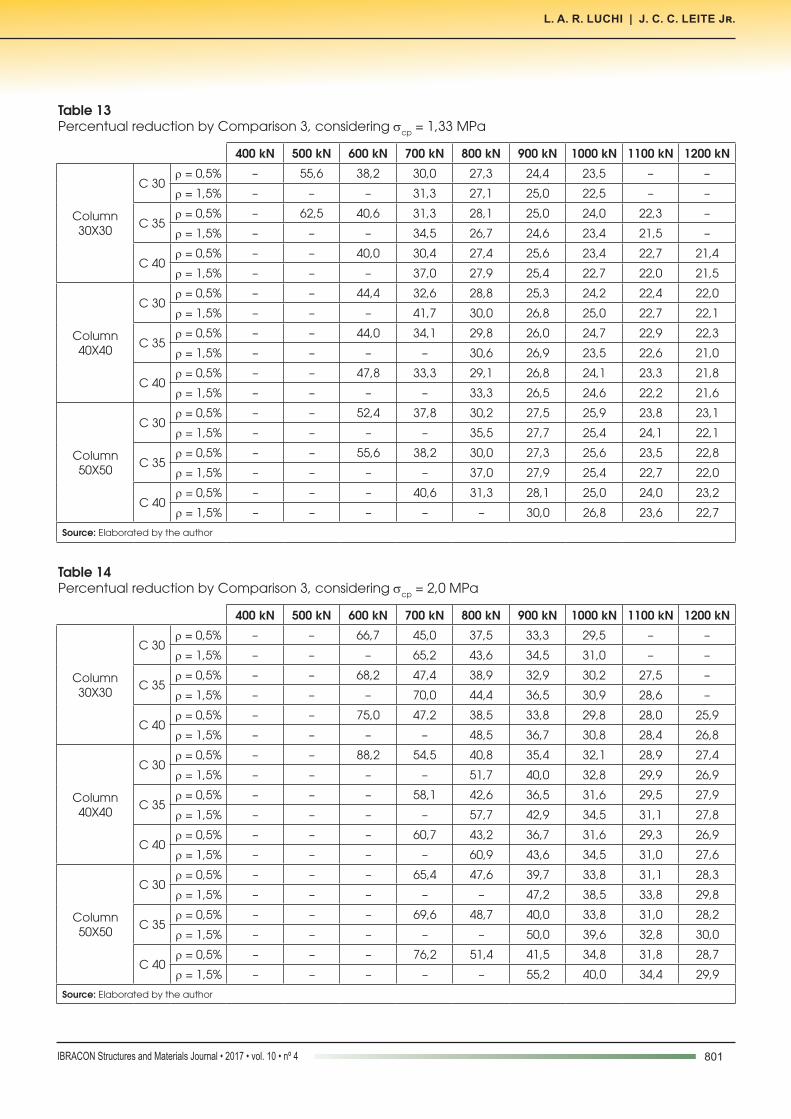
c) Comparison 3
The Tables 13 and 14 show the percentage reductions of punch-ing shear reinforcement obtained when the design using NBR 6118:2014 is replaced by using EC2:2004.The European code provides lower values of shear reinforce-ment to all situations compared, noting that, for smaller loads, the difference between the standards becomes even more significant. For compressive strain (scp) equal to 1,33MPa, it is observed that the difference between them tends to stabilize at 20% by increasing the load. Considering the slabs with scp equal to 2,0MPa, the values calculated by EC2 tend to be 30% lower than those cal-culated by the Brazilian standard, increasing the load. For slabs with smaller prestressing force, raising the flexural reinforcement ratio does not generate a significant reduction to the calculated punching shear reinforcement. However, for slabs with scp equal to 2,0MPa, increase the flexural reinforce-ment causes a expressive reduction in shear reinforcement for loads up to 800kN.
d) Comparison 4
The Tables 15 and 16 show the percentage reductions of punching shear reinforcement obtained when the design using ACI318-11 is replaced by using EC2:2004.Analyzing the four standards compared in this study, it can be said that the greater difference is found between in the designs EC2 and ACI318. The minimum savings generated by the European code was 54% compared to the American standard. For smaller loads, the punching shear reinforcement shear can be reduced by more than 90%. It also observes that for larger sections of columns, keeping constant loading, the economy generated by EC2 tends to increase.In the theoretical examples provided, elevation of prestress-ing increases the savings generated using Eurocode in about 10%. Also, raising the flexural reinforcement ratio generates a reduction about 10% to 15% for the calculated punching shear reinforcement.
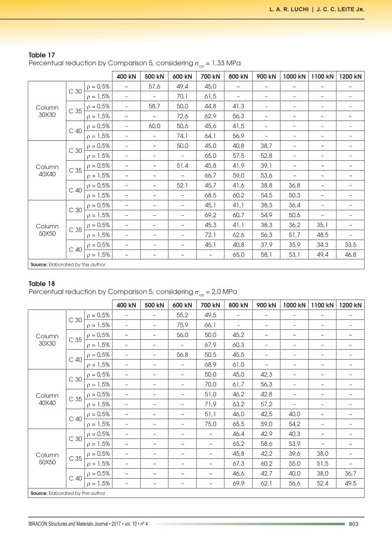
e) Comparison 5
The Tables 17 and 18 show the percentage reductions of punching shear reinforcement obtained when the design using ACI318-11 is replaced by using NBR 6118:2007.The results of the comparison between the NBR 6118:2007 and ACI 318 show that Brazilian standard is more efficient than the American, with reductions greater than 40% on the calculated punching shear reinforcement. It is achieved greater reduction in the reinforcement for smaller loads, as well as the other comparisons.Even though the variation in scp does not significantly change the relationship between the two codes, raising the flexural reinforce-ment generates a reduction of 15% to 20% for shear reinforcement when calculated by the NBR 6118:2007. It is also noted that the
savings generated by the Brazilian standard grows with increasing section of the pillars and constant loads.
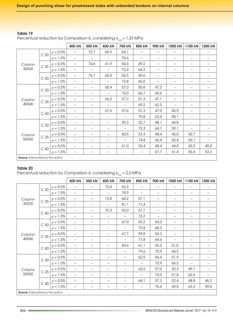
f) Comparison 6
The Tables 19 and 20 show the percentage reductions of punching shear reinforcement obtained when the design using ACI318-11 is replaced by using NBR 6118:2014.It is observed that the difference between the two standards is about 70% for smaller loads and 50% for higher loads.The economy generated by NBR 6118:2014 grows by increas-ing the section of the pillars and constant loads. There is also an approximate 10% increase in the savings obtained by NBR 6118:2014 when the prestressing is elevated and this fact can be observed for all values compared in the results tables.The increase in flexural reinforcement generates a reduction rate of 15% to 20% on the calculated shear reinforcement.
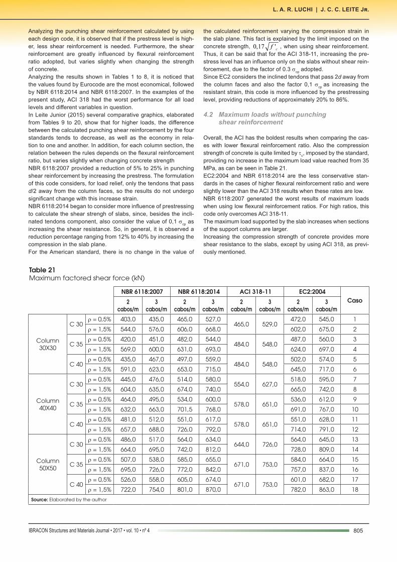
3.4 Maximum loads without punching shear reinforcement
Table 21 shows the maximum factored shear force for each case, and these cases are numbered at the last column of the table.Observing the maximum loads without punching shear reinforce-ment, it can be noticed that ACI 318-11 does not take into account the variation of the flexural reinforcement ratio (ρ), so for the 18 cas-es analyzed, the results vary only with the compression strength of concrete and with the section of supporting columns. Considering ρ equal to 1.5%, the results of ACI and NBR 6118:2007 are always close to each other and also the most conservative.In general, for the odd cases (low flexural reinforcement ratios), NBR 6118: 2007 presents the most conservative results and ACI leads to results bolder than other standards, particularly for larger sections columns. For low reinforcement ratios, only in the cases 1, 3 and 5 EC2:2004 reached load values higher than ACI 318-11.Eurocode and NBR 6118:2014 also generate very similar values in all cases compared and always achieve the highest maximum shear force when ρ is equal to 1.5%.Increasing prestressing had less influence to NBR 6118:2007, re-sulting an increase in the maximum load resistant approximately of 5%. However, the other three design codes had an increase of 10% to 15% in puncture resistance slab.
4. Final considerations
4.1 Punching shear reinforcement calculated by theoretical examples
Initially, it may be affirmed that for all cases, as the load on the slab rises, the necessary punching shear reinforcement have also an increase.There is a reduction of the shear reinforcement calculated increas-ing the section of the columns and concrete strength.For ACI 318, increasing the reinforcement ratio does not influence the shear resistance, but for NBR 6118:2007, NBR 6118:2014 and EC2, there is a considerable decrease in the required punching shear reinforcement.
799IBRACON Structures and Materials Journal • 2017 • vol. 10 • nº 4
L. A. R. LUCHI | J. C. C. LEITE Jr.
Table 9Percentual reduction by Comparison 1, considering scp = 1,33 MPa
400 kN 500 kN 600 kN 700 kN 800 kN 900 kN 1000 kN 1100 kN 1200 kN
Column 30X30
C 30r = 0,5% – 35,7 22,7 16,7 13,2 10,9 9,3 8,1 –
r = 1,5% – – – 23,8 17,2 13,5 11,1 9,4 –
C 35r = 0,5% – 38,5 23,8 17,2 13,5 11,1 9,4 8,2 7,2
r = 1,5% – – – 25,6 18,2 14,1 11,5 9,7 8,4
C 40r = 0,5% – 41,7 25,0 17,9 13,9 11,4 9,6 8,3 7,4
r = 1,5% – – – 27,0 18,9 14,5 11,8 9,9 8,5
Column 40X40
C 30r = 0,5% – – 30,8 21,8 16,9 13,8 11,7 10,1 8,9
r = 1,5% – – – 31,4 21,6 16,4 13,3 11,1 9,6
C 35r = 0,5% – – 30,6 21,2 16,2 13,1 11,0 9,5 8,3
r = 1,5% – – – – 25,0 18,8 15,0 12,5 10,7
C 40r = 0,5% – – 32,4 22,0 16,7 13,4 11,2 9,6 8,5
r = 1,5% – – – – 26,7 19,7 15,6 12,9 11,0
Column 50X50
C 30r = 0,5% – – 38,2 26,0 19,7 15,9 13,3 11,4 10,0
r = 1,5% – – – – 29,5 21,7 17,1 14,1 12,0
C 35r = 0,5% – – 41,9 27,7 20,6 16,5 13,7 11,7 10,2
r = 1,5% – – – 32,5 23,2 18,1 14,8 12,5
C 40r = 0,5% – – – 28,9 21,3 16,9 14,0 11,9 10,4
r = 1,5% – – – – – 23,1 17,6 14,3 12,0
Source: Elaborated by the author
Table 10Percentual reduction by Comparison 1, considering scp = 2,0 MPa
400 kN 500 kN 600 kN 700 kN 800 kN 900 kN 1000 kN 1100 kN 1200 kN
Column 30X30
C 30r = 0,5% – – 38,5 27,3 21,1 17,2 14,6 12,6 –
r = 1,5% – – – 37,8 26,4 20,3 16,5 13,9 –
C 35r = 0,5% – – 40,5 28,3 21,7 17,6 14,9 12,8 11,3
r = 1,5% – – – 41,2 28,0 21,2 17,1 14,3 12,3
C 40r = 0,5% – – 42,9 29,4 22,4 18,1 15,2 13,0 11,5
r = 1,5% – – – – 31,3 23,4 18,8 15,6 13,4
Column 40X40
C 30r = 0,5% – – 50,0 34,0 25,8 20,7 17,3 14,9 13,1
r = 1,5% – – – – 37,0 27,4 21,8 18,1 15,5
C 35r = 0,5% – – 51,6 34,0 25,4 20,3 16,8 14,4 12,6
r = 1,5% – – – – 39,5 28,8 22,7 18,7 15,9
C 40r = 0,5% – – – 37,8 27,9 22,1 18,3 15,6 13,6
r = 1,5% – – – – 41,0 29,1 22,5 18,4 15,5
Column 50X50
C 30r = 0,5% – – – 40,9 30,0 23,7 19,6 16,7 14,5
r = 1,5% – – – – – 34,5 26,8 21,8 18,4
C 35r = 0,5% – – – 45,2 32,8 25,7 21,1 17,9 15,6
r = 1,5% – – – – – 37,3 28,4 22,9 19,2
C 40r = 0,5% – – – 46,2 32,7 25,4 20,7 17,5 15,1
r = 1,5% – – – – – 38,3 28,6 22,8 18,9
Source: Elaborated by the author
800 IBRACON Structures and Materials Journal • 2017 • vol. 10 • nº 4
Design of punching shear for prestressed slabs with unbonded tendons on internal columns
Table 12Percentual reduction by Comparison 2, considering scp = 2,0 MPa
400 kN 500 kN 600 kN 700 kN 800 kN 900 kN 1000 kN 1100 kN 1200 kN
Column 30X30
C 30r = 0,5% – – 79,5 60,0 50,7 44,8 39,8 – –
r = 1,5% – – – 78,4 58,5 47,8 42,4 – –
C 35r = 0,5% – – 81,1 62,3 52,2 44,7 40,6 36,8 –
r = 1,5% – – – 82,4 60,0 50,0 42,7 38,8 –
C 40r = 0,5% – – 85,7 62,7 52,2 45,8 40,4 37,4 34,4
r = 1,5% – – – – 64,6 51,6 43,8 39,6 36,6
Column 40X40
C 30r = 0,5% – – 94,1 70,0 56,1 48,8 43,9 39,5 36,9
r = 1,5% – – – – 69,6 56,5 47,4 42,6 38,2
C 35r = 0,5% – – – 72,3 57,1 49,4 43,2 39,6 37,0
r = 1,5% – – – – 74,4 59,3 49,3 44,0 39,3
C 40r = 0,5% – – – 75,6 59,0 50,6 44,1 40,4 36,8
r = 1,5% – – – – 76,9 60,0 49,3 43,7 38,8
Column 50X50
C 30r = 0,5% – – – 79,5 63,3 53,9 46,7 42,6 38,7
r = 1,5% – – – – – 65,5 54,9 48,3 42,7
C 35r = 0,5% – – – 83,3 65,5 55,4 47,8 43,4 39,3
r = 1,5% – – – – – 68,6 56,7 48,2 43,4
C 40r = 0,5% – – – 87,2 67,3 56,3 48,3 43,7 39,5
r = 1,5% – – – – – 72,3 57,1 49,4 43,2
Source: Elaborated by the author
Table 11Percentual reduction by Comparison 2, considering scp = 1,33 MPa
400 kN 500 kN 600 kN 700 kN 800 kN 900 kN 1000 kN 1100 kN 1200 kN
Column 30X30
C 30r = 0,5% – 71,4 52,3 41,7 36,8 32,6 30,6 – –
r = 1,5% – – – 47,6 39,7 35,1 31,1 – –
C 35r = 0,5% – 76,9 54,8 43,1 37,8 33,3 31,1 28,7 –
r = 1,5% – – – 51,3 40,0 35,2 32,2 29,1 –
C 40r = 0,5% – – 55,0 42,9 37,5 34,1 30,8 29,2 27,2
r = 1,5% – – – 54,1 41,5 36,2 31,8 29,7 28,2
Column 40X40
C 30r = 0,5% – – 61,5 47,3 40,8 35,6 33,0 30,3 28,9
r = 1,5% – – – 60,0 45,1 38,8 34,9 31,3 29,6
C 35r = 0,5% – – 61,1 48,1 41,2 35,7 33,0 30,2 28,8
r = 1,5% – – – 62,5 47,9 40,6 35,0 32,3 29,5
C 40r = 0,5% – – 64,7 48,0 40,9 36,6 32,7 30,7 28,5
r = 1,5% – – – – 51,1 41,0 36,4 32,3 30,3
Column 50X50
C 30r = 0,5% – – 70,6 54,0 43,9 39,0 35,7 32,5 30,8
r = 1,5% – – – – 54,5 43,3 38,2 34,8 31,5
C 35r = 0,5% – – 74,2 55,3 44,4 39,2 35,8 32,4 30,7
r = 1,5% – – – – 57,5 44,6 38,9 34,1 31,7
C 40r = 0,5% – – – 57,8 45,9 40,3 35,5 33,0 31,2
r = 1,5% – – – – 61,1 46,2 39,7 34,5 32,0
Source: Elaborated by the author
801IBRACON Structures and Materials Journal • 2017 • vol. 10 • nº 4
L. A. R. LUCHI | J. C. C. LEITE Jr.
Table 13Percentual reduction by Comparison 3, considering scp = 1,33 MPa
400 kN 500 kN 600 kN 700 kN 800 kN 900 kN 1000 kN 1100 kN 1200 kN
Column 30X30
C 30r = 0,5% – 55,6 38,2 30,0 27,3 24,4 23,5 – –
r = 1,5% – – – 31,3 27,1 25,0 22,5 – –
C 35r = 0,5% – 62,5 40,6 31,3 28,1 25,0 24,0 22,3 –
r = 1,5% – – – 34,5 26,7 24,6 23,4 21,5 –
C 40r = 0,5% – – 40,0 30,4 27,4 25,6 23,4 22,7 21,4
r = 1,5% – – – 37,0 27,9 25,4 22,7 22,0 21,5
Column 40X40
C 30r = 0,5% – – 44,4 32,6 28,8 25,3 24,2 22,4 22,0
r = 1,5% – – – 41,7 30,0 26,8 25,0 22,7 22,1
C 35r = 0,5% – – 44,0 34,1 29,8 26,0 24,7 22,9 22,3
r = 1,5% – – – – 30,6 26,9 23,5 22,6 21,0
C 40r = 0,5% – – 47,8 33,3 29,1 26,8 24,1 23,3 21,8
r = 1,5% – – – – 33,3 26,5 24,6 22,2 21,6
Column 50X50
C 30r = 0,5% – – 52,4 37,8 30,2 27,5 25,9 23,8 23,1
r = 1,5% – – – – 35,5 27,7 25,4 24,1 22,1
C 35r = 0,5% – – 55,6 38,2 30,0 27,3 25,6 23,5 22,8
r = 1,5% – – – – 37,0 27,9 25,4 22,7 22,0
C 40r = 0,5% – – – 40,6 31,3 28,1 25,0 24,0 23,2
r = 1,5% – – – – – 30,0 26,8 23,6 22,7
Source: Elaborated by the author
Table 14Percentual reduction by Comparison 3, considering scp = 2,0 MPa
400 kN 500 kN 600 kN 700 kN 800 kN 900 kN 1000 kN 1100 kN 1200 kN
Column 30X30
C 30r = 0,5% – – 66,7 45,0 37,5 33,3 29,5 – –
r = 1,5% – – – 65,2 43,6 34,5 31,0 – –
C 35r = 0,5% – – 68,2 47,4 38,9 32,9 30,2 27,5 –
r = 1,5% – – – 70,0 44,4 36,5 30,9 28,6 –
C 40r = 0,5% – – 75,0 47,2 38,5 33,8 29,8 28,0 25,9
r = 1,5% – – – – 48,5 36,7 30,8 28,4 26,8
Column 40X40
C 30r = 0,5% – – 88,2 54,5 40,8 35,4 32,1 28,9 27,4
r = 1,5% – – – – 51,7 40,0 32,8 29,9 26,9
C 35r = 0,5% – – – 58,1 42,6 36,5 31,6 29,5 27,9
r = 1,5% – – – – 57,7 42,9 34,5 31,1 27,8
C 40r = 0,5% – – – 60,7 43,2 36,7 31,6 29,3 26,9
r = 1,5% – – – – 60,9 43,6 34,5 31,0 27,6
Column 50X50
C 30r = 0,5% – – – 65,4 47,6 39,7 33,8 31,1 28,3
r = 1,5% – – – – – 47,2 38,5 33,8 29,8
C 35r = 0,5% – – – 69,6 48,7 40,0 33,8 31,0 28,2
r = 1,5% – – – – – 50,0 39,6 32,8 30,0
C 40r = 0,5% – – – 76,2 51,4 41,5 34,8 31,8 28,7
r = 1,5% – – – – – 55,2 40,0 34,4 29,9
Source: Elaborated by the author
802 IBRACON Structures and Materials Journal • 2017 • vol. 10 • nº 4
Design of punching shear for prestressed slabs with unbonded tendons on internal columns
Table 16Percentual reduction by Comparison 4, considering scp = 2,0 MPa
400 kN 500 kN 600 kN 700 kN 800 kN 900 kN 1000 kN 1100 kN 1200 kN
Column 30X30
C 30r = 0,5% – – 90,8 79,8 – – – – –
r = 1,5% – – – 92,7 – – – – –
C 35r = 0,5% – – 91,7 81,1 73,8 – – – –
r = 1,5% – – – 94,3 84,1 – – – –
C 40r = 0,5% – – 93,8 81,6 74,0 – – – –
r = 1,5% – – – – 86,2 – – – –
Column 40X40
C 30r = 0,5% – – – 85,0 75,8 70,4 – – –
r = 1,5% – – – – 88,3 81,0 – – –
C 35r = 0,5% – – – 86,5 76,9 71,0 – – –
r = 1,5% – – – – 90,6 82,6 – – –
C 40r = 0,5% – – – 88,0 77,9 71,6 66,5 – –
r = 1,5% – – – – 92,0 83,6 76,8 – –
Column 50X50
C 30r = 0,5% – – – – 80,4 73,7 68,2 – –
r = 1,5% – – – – – 85,7 79,2 – –
C 35r = 0,5% – – – – 81,3 74,2 68,5 64,9 –
r = 1,5% – – – – – 87,5 80,5 74,9 –
C 40r = 0,5% – – – – 82,5 75,0 69,0 65,1 61,7
r = 1,5% – – – – – 89,5 81,4 75,9 71,3
Source: Elaborated by the author
Table 15Percentual reduction by Comparison 4, considering scp = 1,33 MPa
400 kN 500 kN 600 kN 700 kN 800 kN 900 kN 1000 kN 1100 kN 1200 kN
Column 30X30
C 30r = 0,5% – 87,9 75,9 67,9 – – – – –
r = 1,5% – – – 79,8 – – – – –
C 35r = 0,5% – 90,5 77,4 68,6 63,5 – – – –
r = 1,5% – – – 81,9 73,8 – – – –
C 40r = 0,5% – – 77,8 68,9 63,4 – – – –
r = 1,5% – – – 83,5 74,8 – – – –
Column 40X40
C 30r = 0,5% – – 80,8 71,0 65,0 60,6 – – –
r = 1,5% – – – 86,0 76,7 71,1 – – –
C 35r = 0,5% – – 81,1 71,9 65,8 60,9 – – –
r = 1,5% – – – 87,5 78,6 72,5 – – –
C 40r = 0,5% – – 83,1 71,7 65,5 61,2 57,4 – –
r = 1,5% – – – – 80,5 73,1 68,4 – –
Column 50X50
C 30r = 0,5% – – – 74,7 67,0 62,4 59,1 – –
r = 1,5% – – – – 82,1 74,4 69,5 – –
C 35r = 0,5% – – – 75,6 67,3 62,5 59,1 56,1 –
r = 1,5% – – – – 84,1 75,8 70,5 66,1 –
C 40r = 0,5% – – – 76,8 68,0 62,9 58,6 56,0 54,3
r = 1,5% – – – – 86,4 77,4 71,7 66,9 63,8
Source: Elaborated by the author
803IBRACON Structures and Materials Journal • 2017 • vol. 10 • nº 4
L. A. R. LUCHI | J. C. C. LEITE Jr.
Table 17Percentual reduction by Comparison 5, considering scp = 1,33 MPa
400 kN 500 kN 600 kN 700 kN 800 kN 900 kN 1000 kN 1100 kN 1200 kN
Column 30X30
C 30r = 0,5% – 57,6 49,4 45,0 – – – – –
r = 1,5% – – 70,1 61,5 – – – – –
C 35r = 0,5% – 58,7 50,0 44,8 41,3 – – – –
r = 1,5% – – 72,6 62,9 56,3 – – – –
C 40r = 0,5% – 60,0 50,6 45,6 41,5 – – – –
r = 1,5% – – 74,1 64,1 56,9 – – – –
Column 40X40
C 30r = 0,5% – – 50,0 45,0 40,8 38,7 – – –
r = 1,5% – – – 65,0 57,5 52,8 – – –
C 35r = 0,5% – – 51,4 45,8 41,9 39,1 – – –
r = 1,5% – – – 66,7 59,0 53,6 – – –
C 40r = 0,5% – – 52,1 45,7 41,6 38,8 36,8 – –
r = 1,5% – – – 68,5 60,2 54,5 50,3 – –
Column 50X50
C 30r = 0,5% – – – 45,1 41,1 38,3 36,4 – –
r = 1,5% – – – 69,2 60,7 54,9 50,6 – –
C 35r = 0,5% – – – 45,3 41,1 38,3 36,2 35,1 –
r = 1,5% – – – 72,1 62,6 56,3 51,7 48,5 –
C 40r = 0,5% – – – 45,1 40,8 37,9 35,9 34,3 33,5
r = 1,5% – – – – 65,0 58,1 53,1 49,4 46,8
Source: Elaborated by the author
Table 18Percentual reduction by Comparison 5, considering scp = 2,0 MPa
400 kN 500 kN 600 kN 700 kN 800 kN 900 kN 1000 kN 1100 kN 1200 kN
Column 30X30
C 30r = 0,5% – – 55,2 49,5 – – – – –
r = 1,5% – – 75,9 66,1 – – – – –
C 35r = 0,5% – – 56,0 50,0 45,2 – – – –
r = 1,5% – – – 67,9 60,3 – – – –
C 40r = 0,5% – – 56,8 50,5 45,5 – – – –
r = 1,5% – – – 68,9 61,0 – – – –
Column 40X40
C 30r = 0,5% – – – 50,0 45,0 42,3 – – –
r = 1,5% – – – 70,0 61,7 56,3 – – –
C 35r = 0,5% – – – 51,0 46,2 42,8 – – –
r = 1,5% – – – 71,9 63,2 57,2 – – –
C 40r = 0,5% – – – 51,1 46,0 42,5 40,0 – –
r = 1,5% – – – 75,0 65,5 59,0 54,2 – –
Column 50X50
C 30r = 0,5% – – – – 46,4 42,9 40,3 – –
r = 1,5% – – – – 65,2 58,6 53,9 – –
C 35r = 0,5% – – – – 45,8 42,2 39,6 38,0 –
r = 1,5% – – – – 67,3 60,2 55,0 51,5 –
C 40r = 0,5% – – – – 46,6 42,7 40,0 38,0 36,7
r = 1,5% – – – – 69,9 62,1 56,6 52,4 49,5
Source: Elaborated by the author
804 IBRACON Structures and Materials Journal • 2017 • vol. 10 • nº 4
Design of punching shear for prestressed slabs with unbonded tendons on internal columns
Table 19Percentual reduction by Comparison 6, considering scp = 1,33 MPa
400 kN 500 kN 600 kN 700 kN 800 kN 900 kN 1000 kN 1100 kN 1200 kN
Column 30X30
C 30r = 0,5% – 72,7 60,9 54,1 – – – – –
r = 1,5% – – – 70,6 – – – – –
C 35r = 0,5% – 74,6 61,9 54,3 49,2 – – – –
r = 1,5% – – – 72,4 64,3 – – – –
C 40r = 0,5% – 76,7 63,0 55,3 49,6 – – – –
r = 1,5% – – – 73,8 65,0 – – – –
Column 40X40
C 30r = 0,5% – – 65,4 57,0 50,8 47,2 – – –
r = 1,5% – – – 76,0 66,7 60,6 – – –
C 35r = 0,5% – – 66,2 57,3 51,3 47,1 – – –
r = 1,5% – – – – 69,2 62,3 – – –
C 40r = 0,5% – – 67,6 57,6 51,3 47,0 43,9 – –
r = 1,5% – – – – 70,8 63,4 58,1 – –
Column 50X50
C 30r = 0,5% – – – 59,3 52,7 48,1 44,8 – –
r = 1,5% – – – – 72,3 64,7 59,1 – –
C 35r = 0,5% – – – 60,5 53,3 48,4 45,0 42,7 –
r = 1,5% – – – – 74,8 66,4 60,4 56,1 –
C 40r = 0,5% – – – 61,0 53,4 48,4 44,8 42,2 40,4
r = 1,5% – – – – – 67,7 61,4 56,6 53,2
Source: Elaborated by the author
Table 20Percentual reduction by Comparison 6, considering scp = 2,0 MPa
400 kN 500 kN 600 kN 700 kN 800 kN 900 kN 1000 kN 1100 kN 1200 kN
Column 30X30
C 30r = 0,5% – – 72,4 63,3 – – – – –
r = 1,5% – – – 78,9 – – – – –
C 35r = 0,5% – – 73,8 64,2 57,1 – – – –
r = 1,5% – – – 81,1 71,4 – – – –
C 40r = 0,5% – – 75,3 65,0 57,7 – – – –
r = 1,5% – – – – 73,2 – – – –
Column 40X40
C 30r = 0,5% – – – 67,0 59,2 54,2 – – –
r = 1,5% – – – – 75,8 68,3 – – –
C 35r = 0,5% – – – 67,7 59,8 54,3 – – –
r = 1,5% – – – – 77,8 69,6 – – –
C 40r = 0,5% – – – 69,6 61,1 55,2 51,0 – –
r = 1,5% – – – – 79,6 70,9 64,5 – –
Column 50X50
C 30r = 0,5% – – – – 62,5 56,4 51,9 – –
r = 1,5% – – – – – 72,9 66,2 – –
C 35r = 0,5% – – – – 63,6 57,0 52,3 49,1 –
r = 1,5% – – – – – 75,0 67,8 62,6 –
C 40r = 0,5% – – – – 64,1 57,3 52,4 48,8 46,3
r = 1,5% – – – – – 76,6 69,0 63,3 59,0
Source: Elaborated by the author
805IBRACON Structures and Materials Journal • 2017 • vol. 10 • nº 4
L. A. R. LUCHI | J. C. C. LEITE Jr.
Table 21Maximum factored shear force (kN)
NBR 6118:2007 NBR 6118:2014 ACI 318-11 EC2:2004Caso2
cabos/m3
cabos/m2
cabos/m 3
cabos/m2
cabos/m3
cabos/m2
cabos/m3
cabos/m
Column 30X30
C 30r = 0,5% 403,0 435,0 465,0 527,0
465,0 529,0472,0 545,0 1
r = 1,5% 544,0 576,0 606,0 668,0 602,0 675,0 2
C 35r = 0,5% 420,0 451,0 482,0 544,0
484,0 548,0487,0 560,0 3
r = 1,5% 569,0 600,0 631,0 693,0 624,0 697,0 4
C 40r = 0,5% 435,0 467,0 497,0 559,0
484,0 548,0502,0 574,0 5
r = 1,5% 591,0 623,0 653,0 715,0 645,0 717,0 6
Column 40X40
C 30r = 0,5% 445,0 476,0 514,0 580,0
554,0 627,0518,0 595,0 7
r = 1,5% 604,0 635,0 674,0 740,0 665,0 742,0 8
C 35r = 0,5% 464,0 495,0 534,0 600,0
578,0 651,0536,0 612,0 9
r = 1,5% 632,0 663,0 701,5 768,0 691,0 767,0 10
C 40r = 0,5% 481,0 512,0 551,0 617,0
578,0 651,0551,0 628,0 11
r = 1,5% 657,0 688,0 726,0 792,0 714,0 791,0 12
Column 50X50
C 30r = 0,5% 486,0 517,0 564,0 634,0
644,0 726,0564,0 645,0 13
r = 1,5% 664,0 695,0 742,0 812,0 728,0 809,0 14
C 35r = 0,5% 507,0 538,0 585,0 655,0
671,0 753,0584,0 664,0 15
r = 1,5% 695,0 726,0 772,0 842,0 757,0 837,0 16
C 40r = 0,5% 526,0 558,0 605,0 674,0
671,0 753,0601,0 682,0 17
r = 1,5% 722,0 754,0 801,0 870,0 782,0 863,0 18
Source: Elaborated by the author
Analyzing the punching shear reinforcement calculated by using each design code, it is observed that if the prestress level is high-er, less shear reinforcement is needed. Furthermore, the shear reinforcement are greatly influenced by flexural reinforcement ratio adopted, but varies slightly when changing the strength of concrete.Analyzing the results shown in Tables 1 to 8, it is noticed that the values found by Eurocode are the most economical, followed by NBR 6118:2014 and NBR 6118:2007. In the examples of the present study, ACI 318 had the worst performance for all load levels and different variables in question.In Leite Junior (2015) several comparative graphics, elaborated from Tables 9 to 20, show that for higher loads, the difference between the calculated punching shear reinforcement by the four standards tends to decrease, as well as the economy in rela-tion to one and another. In addition, for each column section, the relation between the rules depends on the flexural reinforcement ratio, but varies slightly when changing concrete strengthNBR 6118:2007 provided a reduction of 5% to 25% in punching shear reinforcement by increasing the prestress. The formulation of this code considers, for load relief, only the tendons that pass d/2 away from the column faces, so the results do not undergo significant change with this increase strain.NBR 6118:2014 began to consider more influence of prestressing to calculate the shear strengh of slabs, since, besides the incli-nated tendons component, also consider the value of 0,1 scp as increasing the shear resistance. So, in general, it is observed a reduction percentage ranging from 12% to 40% by increasing the compression in the slab plane.For the American standard, there is no change in the value of
the calculated reinforcement varying the compression strain in the slab plane. This fact is explained by the limit imposed on the concrete strength, 0,17 'cf , when using shear reinforcement. Thus, it can be said that for the ACI 318-11, increasing the pre-stress level has an influence only on the slabs without shear rein-forcement, due to the factor of 0.3 scp adopted.Since EC2 considers the inclined tendons that pass 2d away from the column faces and also the factor 0,1 scp as increasing the resistant strain, this code is more influenced by the prestressing level, providing reductions of approximately 20% to 86%.
4.2 Maximum loads without punching shear reinforcement
Overall, the ACI has the boldest results when comparing the cas-es with lower flexural reinforcement ratio. Also the compression strength of concrete is quite limited by τc, imposed by the standard, providing no increase in the maximum load value reached from 35 MPa, as can be seen in Table 21.EC2:2004 and NBR 6118:2014 are the less conservative stan-dards in the cases of higher flexural reinforcement ratio and were slightly lower than the ACI 318 results when these rates are low.NBR 6118:2007 generated the worst results of maximum loads when using low flexural reinforcement ratios. For high ratios, this code only overcomes ACI 318-11.The maximum load supported by the slab increases when sections of the support columns are larger.Increasing the compression strength of concrete provides more shear resistance to the slabs, except by using ACI 318, as previ-ously mentioned.
806 IBRACON Structures and Materials Journal • 2017 • vol. 10 • nº 4
Design of punching shear for prestressed slabs with unbonded tendons on internal columns
5. Conclusions
The analyzes show that Eurocode is a standard that generates more economic results of punching shear reinforcement, es-pecially for higher loads, followed by NBR 6118:2014 and NBR 6118:2007. However, ACI is more conservative since the flexural reinforcement ratios do not affect the shear resistance and there are significant limitations relating to the strength of concrete.In general, for slabs with small overload, ACI 318-11 can generate an economic design, since the code can generate a result that dispenses the use of the punching shear reinforcement. EC2:2004 and NBR 6118:2014 have been following, with the NBR 6118:2007 generates the most conservative results. NBR 6118:2014 man-aged to bring the results of the Eurocode, even not considering the calculations the amount of tendons considered by EC2 to relieve vertical load. However, it can be said that the insertion of compres-sive strain in the slab plane has been an important factor in achiev-ing less conservative results of punching shear reinforcements.The compression in the slab plane could have already been stud-ied and adopted before, as this has been done by Americans since the 60s, in a value three times higher than the European stan-dard. Nevertheless, the latest revision of NBR was promising in the sense that the view may be changing aiming greater economy in the calculations, with designs increasingly accurate and efficient, especially for prestressed slabs.It can be seen clearly that the results generated by the ACI are adversely affected by the fact that the contribution of the concrete (τc) and the critical section considered in the calculation of Vp are quite limited. When there is the need of using punching shear re-inforcement, the compression in the slab plane does not influence the calculations due to τc limitation. Thus, the prestressed slab is calculated just like reinforced concrete.If it is necessary to use reinforcement punch, NBR 6118:2007 gen-erates results slightly less conservative than ACI-318, although the compression in the slab plane is not considered.
6. References
[1] AMERICAN CONCRETE INSTITUTE. ACI 318: Building Code Requirements for Structural Concrete. Detroit, 2011.
[2] ASSOCIAÇÃO BRASILEIRA DE NORMAS TÉCNICAS. NBR 6118: Projeto de estruturas de concreto – Procedimen-to. Rio de Janeiro, 2007.
[3] ASSOCIAÇÃO BRASILEIRA DE NORMAS TÉCNICAS. NBR 6118: Projeto de estruturas de concreto – Procedimen-to. Rio de Janeiro, 2014.
[4] EUROPEAN COMMITTEE FOR STANDARDIZATION. EU-ROCODE 2: Design of Concrete Structures – Part 1: Gen-eral Rules and Rules for Building. Bruxelas, 2004
[5] LEITE JUNIOR, Jose Carlos Cirino, Dimensionamento à punção em apoios internos de lajes protendidas sem ade-rência. 2015. 157 f. Dissertação (Mestrado em Engenharia Civil), Universidade Federal do Espírito Santo, Vitória, 2015.