Embed Size (px)
DESCRIPTION
Punching Shear Check
Citation preview
SAFE Technical Note 1
How SAFE Calculates Punching Shear For the
ACI 318-95 Code
(CSA A23.3-94, NZS 3101-95 and IS 456-1978 R1996 Codes Similar)
The information in this document is consistent with SAFE version 6.14 and later
Initial Release Date: November 16, 1998Revision Number: 3
Revision Date: January 11, 1999
Table Of Contents
Item Page
1. Terminology For SAFE Method of Calculating Punching Shear ......................................1
2. Basic Equations For SAFE Method of Calculating Punching Shear .................................1
3. Limitations of Punching Shear Calculations in SAFE ......................................................3
4. Other Comments .............................................................................................................4
5. References.......................................................................................................................4
6. Numerical Example .........................................................................................................5a. Problem Statement.....................................................................................................5b. SAFE Computer Model .............................................................................................6c. Hand Calculation For Interior Column Using SAFE Method .....................................8d. Hand Calculation For Edge Column With Edge Parallel To X-Axis Using
SAFE Method..........................................................................................................11e. Hand Calculation For Edge Column With Edge Parallel To Y-Axis Using
SAFE Method..........................................................................................................14f. Hand Calculation For Corner Column Using SAFE Method ....................................17g. Hand Calculation For Corner Column Using SAFE Method Except That IXY Is
Set To Zero..............................................................................................................20h. Terminology For PCA Publication Method of Calculating Punching Shear..............21i. Basic Equation For PCA Publication Method ..........................................................21j. Hand Calculation For Interior Column Using PCA Publication Method...................22k. Hand Calculation For Edge Column With Edge Parallel To X-Axis Using
PCA Publication Method .........................................................................................24l. Hand Calculation For Edge Column With Edge Parallel To Y-Axis Using
PCA Publication Method .........................................................................................26m. Hand Calculation For Corner Column Using PCA Publication Method....................29n. Comparison Of Punching Shear Stress Results.........................................................31
Safe Technical Note 1 - Punching Shear Revision 3, January 11, 1999Initial Release Date: November 16, 1998 Page 1 of 31
1. Terminology For SAFE Method of Calculating Punching Shear
The following terms are used in describing the SAFE method of calculating punching shear:
b0 = perimeter of critical section for punching sheard = effective depth at critical section for punching shear based on average of d for X
direction and d for Y directionIXX = Moment of inertia of critical section for punching shear about an axis that is parallel to
the global X-axisIYY = Moment of inertia of critical section for punching shear about an axis that is parallel to
the global Y-axisIXY = Product of inertia of critical section for punching shear with respect to the X and Y
planesL = Length of side of critical section for punching shear currently being consideredMUX = Moment about line parallel to X-axis at center of column (positive per right-hand rule)MUY = Moment about line parallel to Y-axis at center of column (positive per right-hand rule)vU = Punching shear stressVU = Shear at center of column (positive upward)x1, y1 = Coordinates of column centroidx2, y2 = Coordinates of center of one side of critical section for punching shearx3, y3 = Coordinates of centroid of critical section for punching shearx4, y4 = Coordinates of location where you are calculating stressγVX = Percent of MUX resisted by shear per ACI 318-95 equations 11-41 and 13-1γVY = Percent of MUY resisted by shear per ACI 318-95 equations 11-41 and 13-1
2. Basic Equations For SAFE Method of Calculating Punching Shear
2
343413
2
343413
0
)]()([)]([
)]()([)]([
XYYYXX
XYXXUUYVY
XYYYXX
XYYYUUXVXUU
III
yyIxxIxxVM
III
xxIyyIyyVM
db
Vv
−−−−−+
−−
−−−−−+=
γ
γEq. 1
∑=
=n
sides
XXXX II1
, where sides refers to the sides of the critical section for punching shear Eq. 2
∑=
=n
sides
YYYY II1
, where sides refers to the sides of the critical section for punching shear Eq. 3
∑=
=n
sides
XYXY II1
, where sides refers to the sides of the critical section for punching shear Eq. 4
Safe Technical Note 1 - Punching Shear Revision 3, January 11, 1999Initial Release Date: November 16, 1998 Page 2 of 31
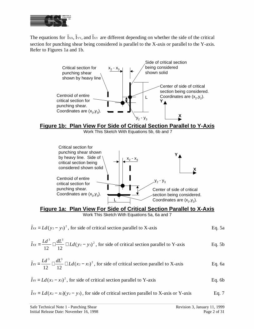
The equations for XYYYXX Iand,I,I are different depending on whether the side of the criticalsection for punching shear being considered is parallel to the X-axis or parallel to the Y-axis.Refer to Figures 1a and 1b.
y2 - y3
L
Critical section forpunching shearshown by heavy line
X
Y
Side of critical sectionbeing consideredshown solid
Center of side of criticalsection being considered.Coordinates are (x2,y2).
Figure 1b: Plan View For Side of Critical Section Parallel to Y-Axis Work This Sketch With Equations 5b, 6b and 7
Centroid of entirecritical section forpunching shear.Coordinates are (x3,y3).
x2 - x3
y2 - y3
L
Critical section forpunching shear shownby heavy line. Side ofcritical section beingconsidered shown solid X
Y
Center of side of criticalsection being considered.Coordinates are (x2,y2).
Figure 1a: Plan View For Side of Critical Section Parallel to X-AxisWork This Sketch With Equations 5a, 6a and 7
Centroid of entirecritical section forpunching shear.Coordinates are (x3,y3).
x2 - x3
232 )( yyLdIXX −= , for side of critical section parallel to X-axis Eq. 5a
232
33
)(1212
yyLddLLd
IXX −++= , for side of critical section parallel to Y-axis Eq. 5b
232
33
)(1212
xxLddLLd
IYY −++= , for side of critical section parallel to X-axis Eq. 6a
232 )( xxLdIYY −= , for side of critical section parallel to Y-axis Eq. 6b
))(( 3232 yyxxLdIXY −−= , for side of critical section parallel to X-axis or Y-axis Eq. 7
Safe Technical Note 1 - Punching Shear Revision 3, January 11, 1999Initial Release Date: November 16, 1998 Page 3 of 31
3. Limitations of Punching Shear Calculations in SAFE
• The shear and moment values used in the punching shear check have not been reduced by theload (or reaction) that is included within the boundaries of the punching shear critical section.Typically the effect of this simplification is small except in some cases for deep slabs (e.g.,mat foundations) and slabs with closely spaced columns.
• Punching shear is calculated for columns punching through a slab or a drop panel. It is notcalculated for a drop panel punching through a slab. The effect of column capitals isincluded in the punching shear calculation.
• The program checks that each slab element in the area enclosed between the face of thecolumn and the critical section for punching shear has identically the same slab propertylabel. If so, the punching shear check is performed, if not, punching shear is not calculatedand N/C is displayed.
• When line objects (beams, walls or releases) frame into a column, punching shear is notcalculated and N/C is displayed.
• If a point load or column falls (call it load/column A) within the critical section for punchingshear for another point load or column (call it load/column B), then it is ignored in thepunching shear calculation (that is, the effect of load/column A is ignored when doingpunching shear calculations for load/column B.)
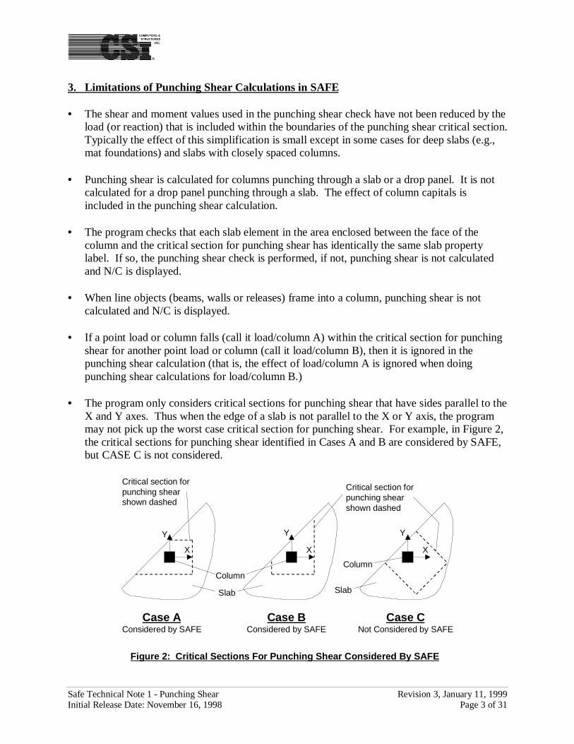
• The program only considers critical sections for punching shear that have sides parallel to theX and Y axes. Thus when the edge of a slab is not parallel to the X or Y axis, the programmay not pick up the worst case critical section for punching shear. For example, in Figure 2,the critical sections for punching shear identified in Cases A and B are considered by SAFE,but CASE C is not considered.
Case AConsidered by SAFE
Y
X
Y
X
Y
X
Slab
Column
Critical section forpunching shearshown dashed
Critical section forpunching shearshown dashed
Column
Slab
Case BConsidered by SAFE
Case CNot Considered by SAFE
Figure 2: Critical Sections For Punching Shear Considered By SAFE
Safe Technical Note 1 - Punching Shear Revision 3, January 11, 1999Initial Release Date: November 16, 1998 Page 4 of 31
4. Other Comments
Equation 1 is based on Chapter 8, Section 50 of S. Timoshenko’s book titled “Strength ofMaterials” (Ref. 1) and on the requirements of codes such as ACI 318-95.
For interior columns and edge columns the punching shear formulation used in SAFE yields thesame results as those that are obtained using the equations given in Figure 18-16 of the PCAPublication (Ref 2). The results are different for corner columns. The reason for the differenceis the IXY term that is included in the SAFE equations but not in the PCA equations. For interiorcolumns and edge columns the IXY term included in the SAFE formulation reduces to zero. TheIXY term is nonzero for corner columns because the X and Y axes are not the principal axes forthis section. If the IXY term in the SAFE equations is set to zero, then the SAFE equations yieldthe same results for corner columns as the PCA equations. (Note that there is no way to actuallyset the IXY term to zero in SAFE.) It could be argued that the SAFE formulation is perhaps moretheoretically sound than the equations given in the PCA Publication. The net effect of the IXY
term is to make the SAFE punching shear calculation for corner columns a little moreconservative than that given in the PCA Publication.
5. References
1. S. Timoshenko, 1958Strength of Materials, Part I, 3rd Edition, D. Van Nostrand Company, New York, NewYork.
2. PCA, 1996Notes On ACI 318-95 Building Code Requirements For Structural Concrete With DesignApplications, Portland Cement Association, Skokie, Illinois.
Safe Technical Note 1 - Punching Shear Revision 3, January 11, 1999Initial Release Date: November 16, 1998 Page 5 of 31
6. Numerical Example
6a. Problem Statement
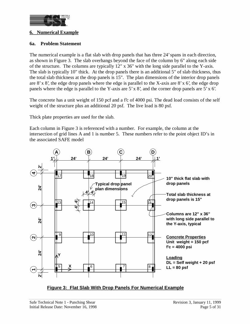
The numerical example is a flat slab with drop panels that has three 24’ spans in each direction,as shown in Figure 3. The slab overhangs beyond the face of the column by 6" along each sideof the structure. The columns are typically 12" x 36" with the long side parallel to the Y-axis.The slab is typically 10" thick. At the drop panels there is an additional 5" of slab thickness, thusthe total slab thickness at the drop panels is 15". The plan dimensions of the interior drop panelsare 8’ x 8’, the edge drop panels where the edge is parallel to the X-axis are 8’ x 6’, the edge droppanels where the edge is parallel to the Y-axis are 5’ x 8’, and the corner drop panels are 5’ x 6’.
The concrete has a unit weight of 150 pcf and a f’c of 4000 psi. The dead load consists of the selfweight of the structure plus an additional 20 psf. The live load is 80 psf.
Thick plate properties are used for the slab.
Each column in Figure 3 is referenced with a number. For example, the column at theintersection of grid lines A and 1 is number 5. These numbers refer to the point object ID’s inthe associated SAFE model
16
4
A
32
1
B C D
X
Y
1’1’ 24’24’24’
2’2’
24’
24’
24’
10" thick flat slab withdrop panels
Total slab thickness atdrop panels is 15"
LoadingDL = Self weight + 20 psfLL = 80 psf
Columns are 12" x 36"with long side parallel tothe Y-axis, typical
4’ 4’
Typical drop panelplan dimensions
4’4’
Concrete PropertiesUnit weight = 150 pcff’c = 4000 psi
5 6 7 8
9 10 11 12
13 14 15
17 18 19 20
Figure 3: Flat Slab With Drop Panels For Numerical Example
Safe Technical Note 1 - Punching Shear Revision 3, January 11, 1999Initial Release Date: November 16, 1998 Page 6 of 31
6b. SAFE Computer Model
In SAFE it is easy to create a computer model for this example, analyze it, design it, and printout the punching shear results. The following steps are required:
1. Set the units to kips and feet.
2. From the File menu select New Model From Template, and then click on the Flat Slabbutton to display the Flat Slab dialog box.
3. In this dialog box:
• Change the Top Edge Distance and Bottom Edge Distance to 2.
• Check the Create Live Load Patterns check box.
• Accept the rest of the default values and click the OK button.
4. From the Define menu select Slab Properties to display the Support Properties dialogbox. Highlight the property named COL, click the Modify\Show Property button todisplay the Slab Property Data dialog box, check the Thick Plate check box and clickOK. Highlight the property named DROP, click the Modify\Show Property button todisplay the Slab Property Data dialog box, check the Thick Plate check box and clickOK. Highlight the property named SLAB, click the Modify\Show Property button todisplay the Slab Property Data dialog box, check the Thick Plate check box and click OKtwice to exit all dialog boxes.
5. From the Define menu select Column Supports to display the Support Properties dialogbox. With the support property named COLUMN highlighted click the Modify\ShowProperty button to display the Column Support Property Data dialog box. In this dialogbox change the Y Dimension to 3. Accept the rest of the default values and click the OKbutton twice to exit all dialog boxes.
6. The SAFE model is now created and ready to run. From the Analyze menu select RunAnalysis. Select a directory and provide a name for the input file and then click the Savebutton to proceed with the analysis.
7. When the analysis is completed review the messages in the Analysis window and clickthe OK button. The model is now ready for design.
8. From the Options menu select Preferences and click the Concrete tab. Verify that theConcrete Design Code selected is ACI 318-95. If necessary, change the selection to thiscode. Click the OK button to exit this dialog box.
9. From the Design menu select Start Design.
Safe Technical Note 1 - Punching Shear Revision 3, January 11, 1999Initial Release Date: November 16, 1998 Page 7 of 31
10. When the design is complete click Display Punching Shear Ratios on the display menu toshow the punching shear results graphically.
11. Change the units to kips and inches.
12. From the File menu select Print Design Tables to display the Design Tables dialog box.
13 In this dialog box:
• In the Design Output area uncheck the Slab Strip Reinforcing check box and checkthe Punching Shear check box.
• In the Design Forces area uncheck the Slab Strip check box.
• Check the Print To File check box. Note that the default name for this file is thename of your model with a .txt extension. Accept this default name.
• Click the OK button to create the punching shear output.
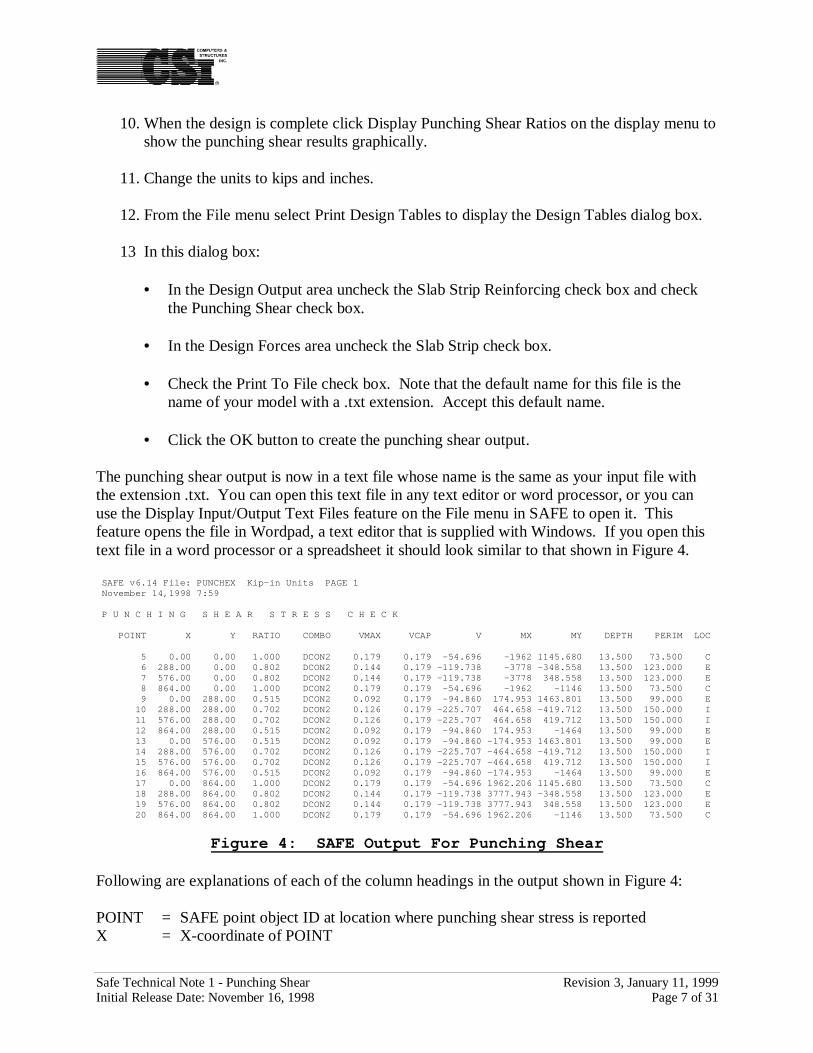
The punching shear output is now in a text file whose name is the same as your input file withthe extension .txt. You can open this text file in any text editor or word processor, or you canuse the Display Input/Output Text Files feature on the File menu in SAFE to open it. Thisfeature opens the file in Wordpad, a text editor that is supplied with Windows. If you open thistext file in a word processor or a spreadsheet it should look similar to that shown in Figure 4.
SAFE v6.14 File: PUNCHEX Kip-in Units PAGE 1 November 14,1998 7:59
P U N C H I N G S H E A R S T R E S S C H E C K
POINT X Y RATIO COMBO VMAX VCAP V MX MY DEPTH PERIM LOC
5 0.00 0.00 1.000 DCON2 0.179 0.179 -54.696 -1962 1145.680 13.500 73.500 C 6 288.00 0.00 0.802 DCON2 0.144 0.179 -119.738 -3778 -348.558 13.500 123.000 E 7 576.00 0.00 0.802 DCON2 0.144 0.179 -119.738 -3778 348.558 13.500 123.000 E 8 864.00 0.00 1.000 DCON2 0.179 0.179 -54.696 -1962 -1146 13.500 73.500 C 9 0.00 288.00 0.515 DCON2 0.092 0.179 -94.860 174.953 1463.801 13.500 99.000 E 10 288.00 288.00 0.702 DCON2 0.126 0.179 -225.707 464.658 -419.712 13.500 150.000 I 11 576.00 288.00 0.702 DCON2 0.126 0.179 -225.707 464.658 419.712 13.500 150.000 I 12 864.00 288.00 0.515 DCON2 0.092 0.179 -94.860 174.953 -1464 13.500 99.000 E 13 0.00 576.00 0.515 DCON2 0.092 0.179 -94.860 -174.953 1463.801 13.500 99.000 E 14 288.00 576.00 0.702 DCON2 0.126 0.179 -225.707 -464.658 -419.712 13.500 150.000 I 15 576.00 576.00 0.702 DCON2 0.126 0.179 -225.707 -464.658 419.712 13.500 150.000 I 16 864.00 576.00 0.515 DCON2 0.092 0.179 -94.860 -174.953 -1464 13.500 99.000 E 17 0.00 864.00 1.000 DCON2 0.179 0.179 -54.696 1962.206 1145.680 13.500 73.500 C 18 288.00 864.00 0.802 DCON2 0.144 0.179 -119.738 3777.943 -348.558 13.500 123.000 E 19 576.00 864.00 0.802 DCON2 0.144 0.179 -119.738 3777.943 348.558 13.500 123.000 E 20 864.00 864.00 1.000 DCON2 0.179 0.179 -54.696 1962.206 -1146 13.500 73.500 C
Figure 4: SAFE Output For Punching Shear
Following are explanations of each of the column headings in the output shown in Figure 4:
POINT = SAFE point object ID at location where punching shear stress is reportedX = X-coordinate of POINT
Safe Technical Note 1 - Punching Shear Revision 3, January 11, 1999Initial Release Date: November 16, 1998 Page 8 of 31
Y = Y-coordinate of POINTRATIO = Punching shear stress divided by punching shear capacityCOMBO = Load combination that produces maximum punching shear stressVMAX = Punching shear stress with the maximum absolute valueVCAP = Punching shear stress capacity with a phi factor included, i.e., φvC
V = Shear used in punching shear stress calculationMX = Moment about a line through the column centroid and parallel to the X-axis used in
punching shear stress calculationMY = Moment about a line through the column centroid and parallel to the Y-axis used in
punching shear stress calculationDEPTH = Effective depth for punching shear calculated as the average of the effective depths
in the X and Y directionsPERIM = Perimeter length of critical section for punching shearLOC = Identifier for column location: I is an interior column, E is an edge column, and C is
a corner column
We will now derive some of the results shown in Figure 4 using hand calculations. The resultswe will calculate are the shear stress, shear capacity and the shear ratio for an interior column, anedge column with the edge parallel to the X-axis, an edge column with the edge parallel to the Y-axis, and a corner column. We will calculate these values using the SAFE formulation and thencalculate them again using the formulation in the PCA Publication (Ref 2). Finally, we willcompare the results obtained from SAFE, our hand calculations using the SAFE formulation, andour hand calculations using the PCA Publication formulation.
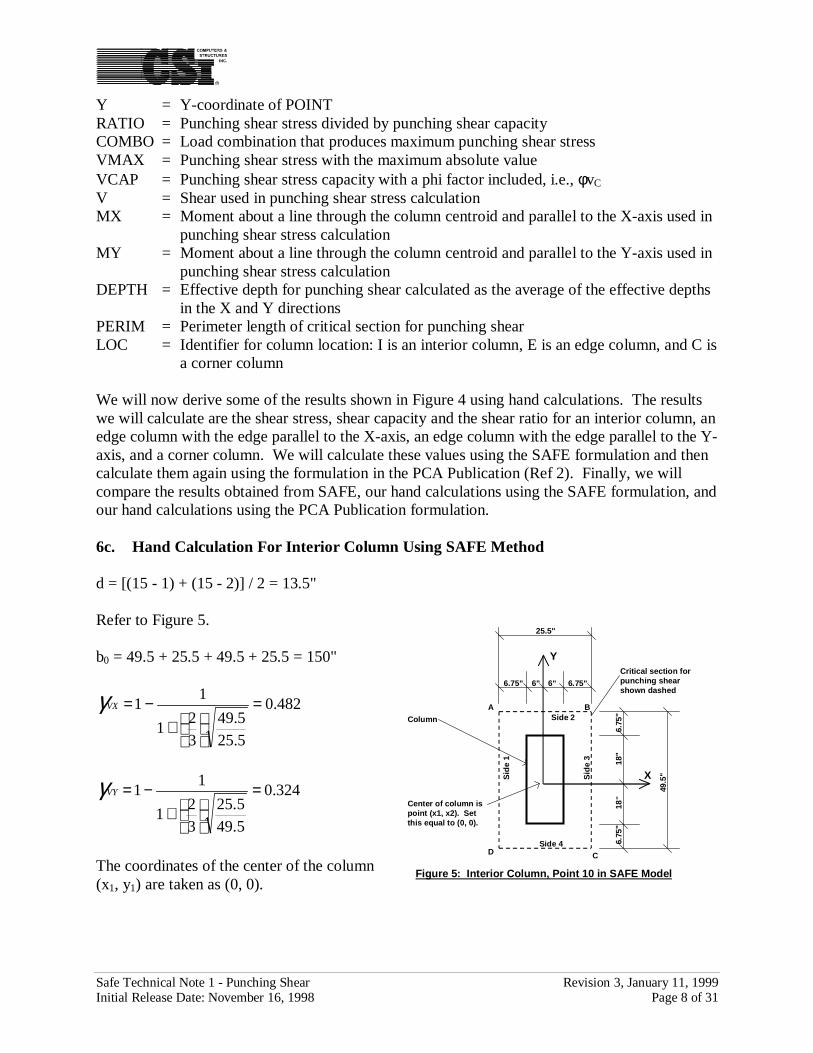
6c. Hand Calculation For Interior Column Using SAFE Method
d = [(15 - 1) + (15 - 2)] / 2 = 13.5"
Refer to Figure 5.
b0 = 49.5 + 25.5 + 49.5 + 25.5 = 150"
482.0
5.25
5.49
3
21
11 =
+
−=VXγ
324.0
5.49
5.25
3
21
11 =
+
−=VYγ
The coordinates of the center of the column(x1, y1) are taken as (0, 0).
6.75
"18
"18
"6.
75"
6" 6" 6.75"6.75"
X
Y
Figure 5: Interior Column, Point 10 in SAFE Model
49.5
"
25.5"
Critical section forpunching shearshown dashed
Side 2
Sid
e 3
A B
C
Center of column ispoint (x1, x2). Setthis equal to (0, 0).
D
Column
Sid
e 1
Side 4
Safe Technical Note 1 - Punching Shear Revision 3, January 11, 1999Initial Release Date: November 16, 1998 Page 9 of 31
The following table is used for calculating the centroid of the critical section for punching shear.Side 1 , Side 2, Side 3 and Side 4 refer to the sides of the critical section for punching shear asidentified in Figure 5.
"02025
023 === ∑
Ld
Ldxx
"02025
023 === ∑
Ld
Ldyy
The following table is used to calculate IXX, IYY and IXY. The values for IXX, IYY and IXY aregiven in the column titled “Sum”.
From the SAFE output at column point 10:
VU = -225.707 kMUX = 464.658 k-inMUY = -419.712 k-in
At the point labeled A in Figure 5, x4 = -12.75 and y4 = 24.75, thus:
Item Side 1 Side 2 Side 3 Side 4 Sumx2 -12.75 0 12.75 0 N.A.y2 0 24.75 0 -24.75 N.A.L 49.5 25.5 49.5 25.5 b0 = 150d 13.5 13.5 13.5 13.5 N.A.
Ld 668.25 344.25 668.25 344.25 2025Ldx2 -8520.19 0 8520.19 0 0Ldy2 0 8520.19 0 -8520.19 0
Item Side 1 Side 2 Side 3 Side 4 SumL 49.5 25.5 49.5 25.5 N.A.d 13.5 13.5 13.5 13.5 N.A.
x2 - x3 -12.75 0 12.75 0 N.A.y2 - y3 0 24.75 0 24.75 N.A.
Parallel to Y-Axis X-axis Y-Axis X-axis N.A.Equations 5b, 6b, 7 5a, 6a, 7 5b, 6b, 7 5a, 6a, 7 N.A.
IXX 0 357472 0 357472 714944IYY 132515 0 132515 0 265030IXY 0 0 0 0 0
Safe Technical Note 1 - Punching Shear Revision 3, January 11, 1999Initial Release Date: November 16, 1998 Page 10 of 31
2
2
)0()265030)(714944(
)]075.24)(0()075.12(714944[)]00)(707.225(712.419[324.0
)0()265030)(714944(
)]075.12)(0()075.24(265030[)]00)(707.225(658.464[482.0
5.13*150
707.225
−−−−−−−−−
−−
−−−−−−−+−=Uv
vU = -0.111 + 0.008 - 0.007 = -0.110 ksi at point A
At the point labeled B in Figure 5, x4 = 12.75 and y4 = 24.75, thus:
2
2
)0()265030)(714944(
)]075.24)(0()075.12(714944[)]00)(707.225(712.419[324.0
)0()265030)(714944(
)]075.12)(0()075.24(265030[)]00)(707.225(658.464[482.0
5.13*150
707.225
−−−−−−−−
−−
−−−−−−+−=Uv
vU = -0.111 + 0.008 + 0.007 = -0.097 ksi at point B
At the point labeled C in Figure 5, x4 = 12.75 and y4 = -24.75, thus:
2
2
)0()265030)(714944(
)]075.24)(0()075.12(714944[)]00)(707.225(712.419[324.0
)0()265030)(714944(
)]075.12)(0()075.24(265030[)]00)(707.225(658.464[482.0
5.13*150
707.225
−−−−−−−−−
−−
−−−−−−−+−=Uv
vU = -0.111 - 0.008 + 0.007 = -0.113 ksi at point C
At the point labeled D in Figure 5, x4 = -12.75 and y4 = -24.75, thus:
2
2
)0()265030)(714944(
)]075.24)(0()075.12(714944[)]00)(707.225(712.419[324.0
)0()265030)(714944(
)]075.12)(0()075.24(265030[)]00)(707.225(658.464[482.0
5.13*150
707.225
−−−−−−−−−−
−−
−−−−−−−+−=Uv
vU = -0.111 - 0.008 - 0.007 = -0.126 ksi at point D
Point D has the largest absolute value of vu, thus vmax = 0.126 ksi
The shear capacity is calculated based on the smallest of ACI 318-95 equations 11-35, 11-36 and11-37 with the b0 and d terms removed to convert force to stress.
179.01000
400012/36
4285.0
=
+
=Cvϕ ksi per equation 11-35
Safe Technical Note 1 - Punching Shear Revision 3, January 11, 1999Initial Release Date: November 16, 1998 Page 11 of 31
301.01000
40002150
5.13*4085.0
=
+
=Cvϕ ksi per equation 11-36
215.01000
4000*4*85.0 ==Cvϕ ksi per equation 11-37
Equation 11-35 yields the smallest value of φvC = 0.179 ksi , and thus this is the shear capacity.
702.0179.0
126.0 ===C
U
v
vRatioShear
ϕ
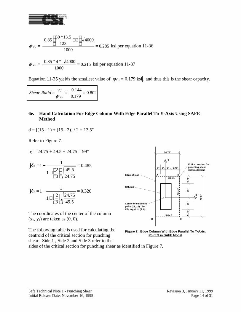
6d. Hand Calculation For Edge Column With Edge Parallel To X-Axis Using SAFEMethod
d = [(15 - 1) + (15 - 2)] / 2 = 13.5"
Refer to Figure 6.
b0 = 48.75 + 25.5 + 48.75 = 123"
480.0
5.25
75.48
3
21
11 =
+
−=VXγ
325.0
75.48
5.25
3
21
11 =
+
−=VYγ
The coordinates of the center of thecolumn (x1, y1) are taken as (0, 0).
The following table is used forcalculating the centroid of the critical section for punching shear. Side 1 , Side 2 and Side 3 referto the sides of the critical section for punching shear as identified in Figure 6.
6"18
"18
"6.
75"
6" 6" 6.75"6.75"
X
Y
Figure 6: Edge Column With Edge Parallel To X-Axis,Point 6 in SAFE Model
48.7
5"
25.5"
Critical section forpunching shearshown dashed
Side 2
Sid
e 3
A B
C
Column
Edge of slabCenter of column ispoint (x1, x2). Setthis equal to (0, 0).
D
Sid
e 1
Safe Technical Note 1 - Punching Shear Revision 3, January 11, 1999Initial Release Date: November 16, 1998 Page 12 of 31
"05.1660
023 === ∑
Ld
Ldxx
"43.55.1660
78.901323 === ∑
Ld
Ldyy
The following table is used to calculate IXX, IYY and IXY. The values for IXX, IYY and IXY aregiven in the column titled “Sum”.
From the SAFE output at column point 6:
VU = -119.738 kMUX = 3778 k-inMUY = -348.588 k-in
At the point labeled A in Figure 6, x4 = -12.75 and y4 = 24.75, thus:
Item Side 1 Side 2 Side 3 Sumx2 -12.75 0 12.75 N.A.y2 0.375 24.75 0.375 N.A.L 48.75 25.5 48.75 b0 = 123d 13.5 13.5 13.5 N.A.
Ld 658.125 344.25 658.125 1660.5Ldx2 -8391.09 0 8391.09 0Ldy2 246.80 8520.19 246.80 9013.78
Item Side 1 Side 2 Side 3 SumL 48.75 25.5 48.75 N.A.d 13.5 13.5 13.5 N.A.
x2 - x3 -12.75 0 12.75 N.A.y2 - y3 -5.05 19.32 -5.05 N.A.
Parallel to Y-Axis X-axis Y-Axis N.A.Equations 5b, 6b, 7 5a, 6a, 7 5b, 6b, 7 N.A.
IXX 157141 128518 157141 442800IYY 106986 23883 106986 237855IXY 42403 0 -42403 0
Safe Technical Note 1 - Punching Shear Revision 3, January 11, 1999Initial Release Date: November 16, 1998 Page 13 of 31
2
2
)0()237855)(442800(
)]43.575.24)(0()075.12(442800[)]00)(119.738(588.348[325.0
)0()237855)(442800(
)]075.12)(0()43.575.24(237855[)]043.5)(119.738(3778[480.0
5.13*123
119.738
−−−−−−−−−
−−
−−−−−−−+−=Uv
vU = -0.0721 - 0.0655 - 0.0061 = -0.144 ksi at point A
At the point labeled B in Figure 6, x4 = 12.75 and y4 = 24.75, thus:
2
2
)0()237855)(442800(
)]43.575.24)(0()075.12(442800[)]00)(119.738(588.348[325.0
)0()237855)(442800(
)]075.12)(0()43.575.24(237855[)]043.5)(119.738(3778[480.0
5.13*123
119.738
−−−−−−−−
−−
−−−−−−+−=Uv
vU = -0.072 - 0.065 + 0.006 = -0.131 ksi at point B
At the point labeled C in Figure 6, x4 = 12.75 and y4 = -24, thus:
2
2
)0()237855)(442800(
)]43.524)(0()075.12(442800[)]00)(119.738(588.348[325.0
)0()237855)(442800(
)]075.12)(0()43.524(237855[)]043.5)(119.738(3778[480.0
5.13*123
119.738
−−−−−−−−−
−−
−−−−−−−+−=Uv
vU = -0.072 + 0.100 + 0.006 = 0.034 ksi at point C
At the point labeled D in Figure 6, x4 = -12.75 and y4 = -24, thus:
2
2
)0()237855)(442800(
)]43.524)(0()075.12(442800[)]00)(119.738(588.348[325.0
)0()237855)(442800(
)]075.12)(0()43.524(237855[)]043.5)(119.738(3778[480.0
5.13*123
119.738
−−−−−−−−−−
−−
−−−−−−−−+−=Uv
vU = -0.072 + 0.100 - 0.006 = 0.022 ksi at point D
Point A has the largest absolute value of vu, thus vmax = 0.144 ksi
The shear capacity is calculated based on the smallest of ACI 318-95 equations 11-35, 11-36 and11-37 with the b0 and d terms removed to convert force to stress.
179.01000
400012/36
4285.0
=
+
=Cvϕ ksi per equation 11-35
Safe Technical Note 1 - Punching Shear Revision 3, January 11, 1999Initial Release Date: November 16, 1998 Page 14 of 31
285.01000
40002123
5.13*3085.0
=
+
=Cvϕ ksi per equation 11-36
215.01000
4000*4*85.0 ==Cvϕ ksi per equation 11-37
Equation 11-35 yields the smallest value of φvC = 0.179 ksi , and thus this is the shear capacity.
802.0179.0
144.0 ===C
U
v
vRatioShear
ϕ
6e. Hand Calculation For Edge Column With Edge Parallel To Y-Axis Using SAFEMethod
d = [(15 - 1) + (15 - 2)] / 2 = 13.5"
Refer to Figure 7.
b0 = 24.75 + 49.5 + 24.75 = 99"
485.0
75.24
5.49
3
21
11 =
+
−=VXγ
320.0
5.49
75.24
3
21
11 =
+
−=VYγ
The coordinates of the center of the column(x1, y1) are taken as (0, 0).
The following table is used for calculating thecentroid of the critical section for punchingshear. Side 1 , Side 2 and Side 3 refer to thesides of the critical section for punching shear as identified in Figure 7.
6.75
"18
"18
"6.
75"
6" 6" 6.75"6"
X
Y
Figure 7: Edge Column With Edge Parallel To Y-Axis,Point 9 in SAFE Model
49.5
"
24.75"
Critical section forpunching shearshown dashed
Side 1S
ide
2A B
C
Column
Edge of slab
Center of column ispoint (x1, x2). Setthis equal to (0, 0).
D
Side 3
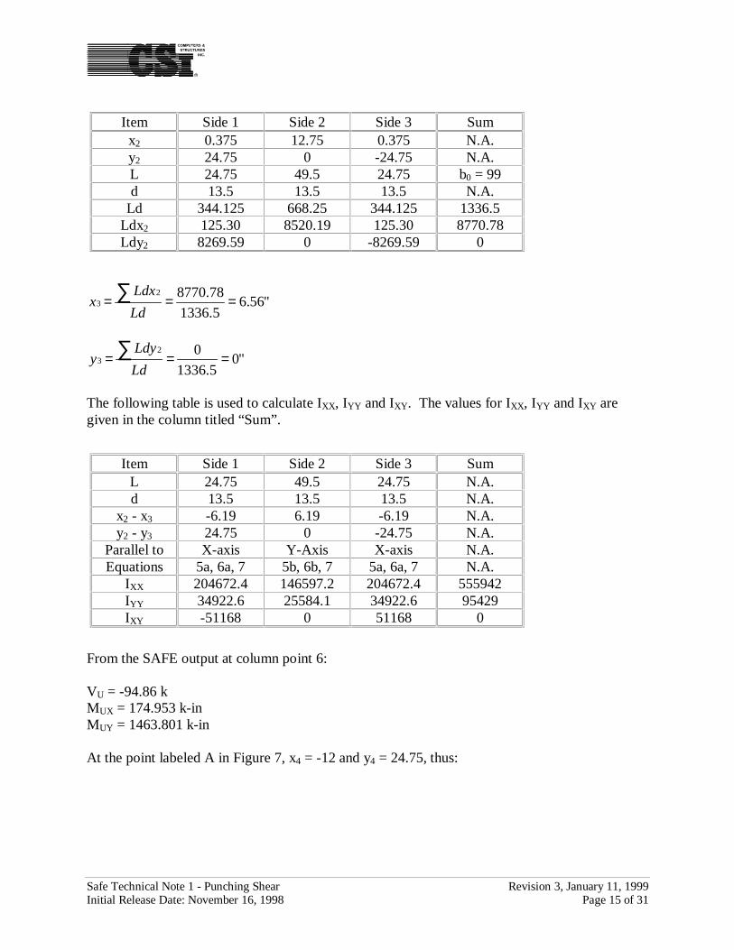
Safe Technical Note 1 - Punching Shear Revision 3, January 11, 1999Initial Release Date: November 16, 1998 Page 15 of 31
"56.65.1336
78.877023 === ∑
Ld
Ldxx
"05.1336
023 === ∑
Ld
Ldyy
The following table is used to calculate IXX, IYY and IXY. The values for IXX, IYY and IXY aregiven in the column titled “Sum”.
From the SAFE output at column point 6:
VU = -94.86 kMUX = 174.953 k-inMUY = 1463.801 k-in
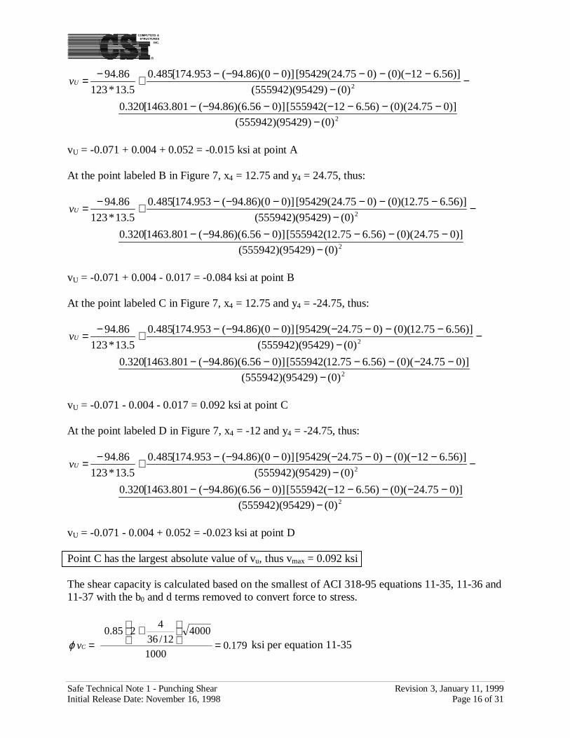
At the point labeled A in Figure 7, x4 = -12 and y4 = 24.75, thus:
Item Side 1 Side 2 Side 3 Sumx2 0.375 12.75 0.375 N.A.y2 24.75 0 -24.75 N.A.L 24.75 49.5 24.75 b0 = 99d 13.5 13.5 13.5 N.A.
Ld 344.125 668.25 344.125 1336.5Ldx2 125.30 8520.19 125.30 8770.78Ldy2 8269.59 0 -8269.59 0
Item Side 1 Side 2 Side 3 SumL 24.75 49.5 24.75 N.A.d 13.5 13.5 13.5 N.A.
x2 - x3 -6.19 6.19 -6.19 N.A.y2 - y3 24.75 0 -24.75 N.A.
Parallel to X-axis Y-Axis X-axis N.A.Equations 5a, 6a, 7 5b, 6b, 7 5a, 6a, 7 N.A.
IXX 204672.4 146597.2 204672.4 555942IYY 34922.6 25584.1 34922.6 95429IXY -51168 0 51168 0
Safe Technical Note 1 - Punching Shear Revision 3, January 11, 1999Initial Release Date: November 16, 1998 Page 16 of 31
2
2
)0()95429)(555942(
)]075.24)(0()56.612(555942[)]056.6)(86.49(801.1463[320.0
)0()95429)(555942(
)]56.612)(0()075.24(95429[)]00)(86.49(953.174[485.0
5.13*123
86.49
−−−−−−−−
−−
−−−−−−−+−=Uv
vU = -0.071 + 0.004 + 0.052 = -0.015 ksi at point A
At the point labeled B in Figure 7, x4 = 12.75 and y4 = 24.75, thus:
2
2
)0()95429)(555942(
)]075.24)(0()56.675.12(555942[)]056.6)(86.49(801.1463[320.0
)0()95429)(555942(
)]56.675.12)(0()075.24(95429[)]00)(86.49(953.174[485.0
5.13*123
86.49
−−−−−−−
−−
−−−−−−+−=Uv
vU = -0.071 + 0.004 - 0.017 = -0.084 ksi at point B
At the point labeled C in Figure 7, x4 = 12.75 and y4 = -24.75, thus:
2
2
)0()95429)(555942(
)]075.24)(0()56.675.12(555942[)]056.6)(86.49(801.1463[320.0
)0()95429)(555942(
)]56.675.12)(0()075.24(95429[)]00)(86.49(953.174[485.0
5.13*123
86.49
−−−−−−−−
−−
−−−−−−−+−=Uv
vU = -0.071 - 0.004 - 0.017 = 0.092 ksi at point C
At the point labeled D in Figure 7, x4 = -12 and y4 = -24.75, thus:
2
2
)0()95429)(555942(
)]075.24)(0()56.612(555942[)]056.6)(86.49(801.1463[320.0
)0()95429)(555942(
)]56.612)(0()075.24(95429[)]00)(86.49(953.174[485.0
5.13*123
86.49
−−−−−−−−−
−−
−−−−−−−−+−=Uv
vU = -0.071 - 0.004 + 0.052 = -0.023 ksi at point D
Point C has the largest absolute value of vu, thus vmax = 0.092 ksi
The shear capacity is calculated based on the smallest of ACI 318-95 equations 11-35, 11-36 and11-37 with the b0 and d terms removed to convert force to stress.
179.01000
400012/36
4285.0
=
+
=Cvϕ ksi per equation 11-35
Safe Technical Note 1 - Punching Shear Revision 3, January 11, 1999Initial Release Date: November 16, 1998 Page 17 of 31
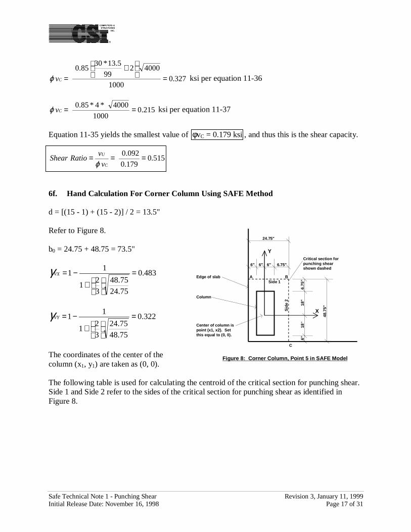
327.01000
4000299
5.13*3085.0
=
+
=Cvϕ ksi per equation 11-36
215.01000
4000*4*85.0 ==Cvϕ ksi per equation 11-37
Equation 11-35 yields the smallest value of φvC = 0.179 ksi , and thus this is the shear capacity.
515.0179.0
092.0 ===C
U
v
vRatioShear
ϕ
6f. Hand Calculation For Corner Column Using SAFE Method
d = [(15 - 1) + (15 - 2)] / 2 = 13.5"
Refer to Figure 8.
b0 = 24.75 + 48.75 = 73.5"
483.0
75.24
75.48
3
21
11 =
+
−=VXγ
322.0
75.48
75.24
3
21
11 =
+
−=VYγ
The coordinates of the center of thecolumn (x1, y1) are taken as (0, 0).
The following table is used for calculating the centroid of the critical section for punching shear.Side 1 and Side 2 refer to the sides of the critical section for punching shear as identified inFigure 8.
6"18
"18
"6.
75"
6" 6" 6.75"6"
X
Y
Figure 8: Corner Column, Point 5 in SAFE Model
48.7
5"
24.75"
Critical section forpunching shearshown dashed
Side 1S
ide
2
A B
C
Column
Edge of slab
Center of column ispoint (x1, x2). Setthis equal to (0, 0).
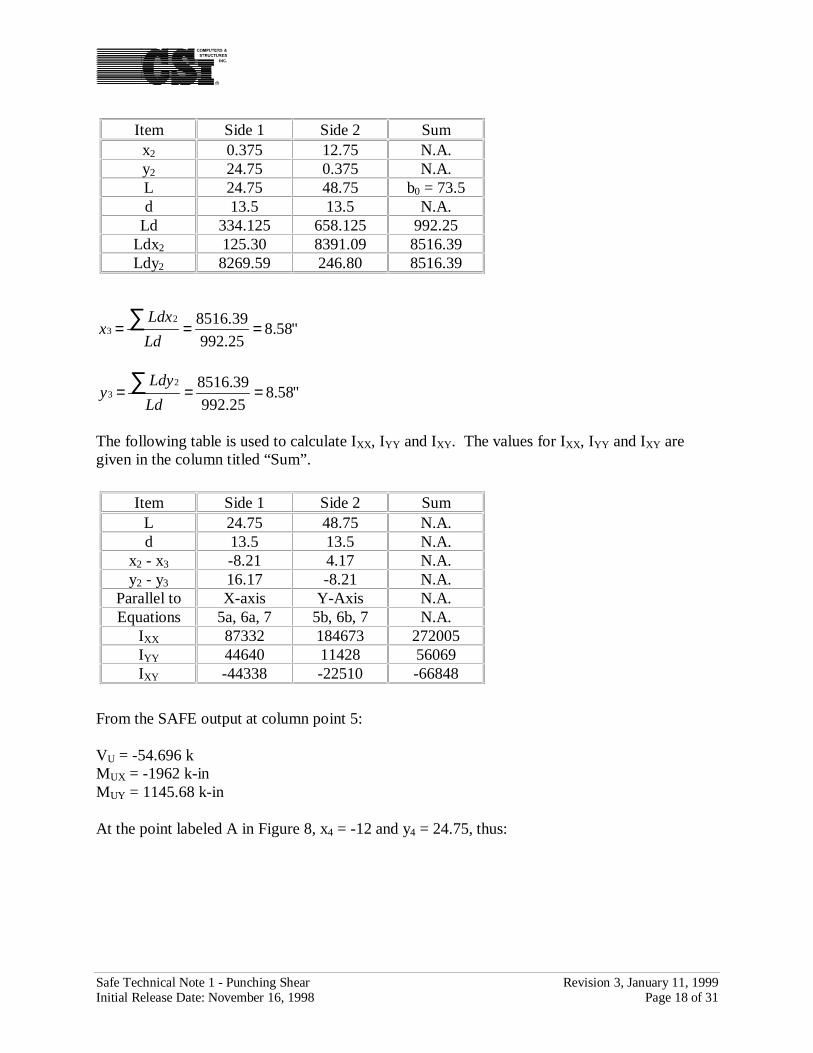
Safe Technical Note 1 - Punching Shear Revision 3, January 11, 1999Initial Release Date: November 16, 1998 Page 18 of 31
"58.825.992
39.851623 === ∑
Ld
Ldxx
"58.825.992
39.851623 === ∑
Ld
Ldyy
The following table is used to calculate IXX, IYY and IXY. The values for IXX, IYY and IXY aregiven in the column titled “Sum”.
From the SAFE output at column point 5:
VU = -54.696 kMUX = -1962 k-inMUY = 1145.68 k-in
At the point labeled A in Figure 8, x4 = -12 and y4 = 24.75, thus:
Item Side 1 Side 2 Sumx2 0.375 12.75 N.A.y2 24.75 0.375 N.A.L 24.75 48.75 b0 = 73.5d 13.5 13.5 N.A.
Ld 334.125 658.125 992.25Ldx2 125.30 8391.09 8516.39Ldy2 8269.59 246.80 8516.39
Item Side 1 Side 2 SumL 24.75 48.75 N.A.d 13.5 13.5 N.A.
x2 - x3 -8.21 4.17 N.A.y2 - y3 16.17 -8.21 N.A.
Parallel to X-axis Y-Axis N.A.Equations 5a, 6a, 7 5b, 6b, 7 N.A.
IXX 87332 184673 272005IYY 44640 11428 56069IXY -44338 -22510 -66848
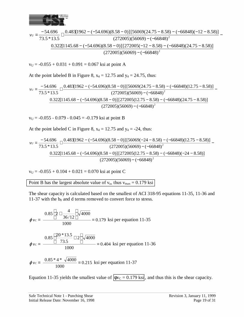
Safe Technical Note 1 - Punching Shear Revision 3, January 11, 1999Initial Release Date: November 16, 1998 Page 19 of 31
2
2
)66848()56069)(272005(
)]58.875.24)(66848()58.812(272005[)]058.8)(696.54(68.1145[322.0
)66848()56069)(272005(
)]58.812)(66848()58.875.24(56069[)]058.8)(696.54(1962[483.0
5.13*5.73
696.54
−−−−−−−−−−
−−−
−−−−−−−−+−=Uv
vU = -0.055 + 0.031 + 0.091 = 0.067 ksi at point A
At the point labeled B in Figure 8, x4 = 12.75 and y4 = 24.75, thus:
2
2
)66848()56069)(272005(
)]58.875.24)(66848()58.875.12(272005[)]058.8)(696.54(68.1145[322.0
)66848()56069)(272005(
)]58.875.12)(66848()58.875.24(56069[)]058.8)(696.54(1962[483.0
5.13*5.73
696.54
−−−−−−−−−
−−−
−−−−−−−+−=Uv
vU = -0.055 - 0.079 - 0.045 = -0.179 ksi at point B
At the point labeled C in Figure 8, x4 = 12.75 and y4 = -24, thus:
2
2
)66848()56069)(272005(
)]58.824)(66848()58.875.12(272005[)]058.8)(696.54(68.1145[322.0
)66848()56069)(272005(
)]58.875.12)(66848()58.824(56069[)]058.8)(696.54(1962[483.0
5.13*5.73
696.54
−−−−−−−−−−
−−−
−−−−−−−−+−=Uv
vU = -0.055 + 0.104 + 0.021 = 0.070 ksi at point C
Point B has the largest absolute value of vu, thus vmax = 0.179 ksi
The shear capacity is calculated based on the smallest of ACI 318-95 equations 11-35, 11-36 and11-37 with the b0 and d terms removed to convert force to stress.
179.01000
400012/36
4285.0
=
+
=Cvϕ ksi per equation 11-35
404.01000
400025.73
5.13*2085.0
=
+
=Cvϕ ksi per equation 11-36
215.01000
4000*4*85.0 ==Cvϕ ksi per equation 11-37
Equation 11-35 yields the smallest value of φvC = 0.179 ksi , and thus this is the shear capacity.

Safe Technical Note 1 - Punching Shear Revision 3, January 11, 1999Initial Release Date: November 16, 1998 Page 20 of 31
000.1179.0
179.0 ===C
U
v
vRatioShear
ϕ
6g. Hand Calculation For Corner Column Using SAFE Method Except That IXY Is Set ToZero
This calculation is done for comparison with the corner calculation using the PCA Publicationmethod (Ref. 2). Note that the computer program SAFE does not do the calculation with IXY setto zero.
The calculations in this case are exactly the same as in Section 6f, except that IXY is set to zero.Thus, using the intermediate results in Section 6f we can go right to calculating the stresses.
At the point labeled A in Figure 8, x4 = -12 and y4 = 24.75, thus:
2
2
)0()56069)(272005(
)]58.875.24)(0()58.812(272005[)]058.8)(696.54(68.1145[322.0
)0()56069)(272005(
)]58.812)(0()58.875.24(56069[)]058.8)(696.54(1962[483.0
5.13*5.73
696.54
−−−−−−−−
−−
−−−−−−−+−=Uv
vU = -0.055 - 0.043 + 0.080 = -0.018 ksi at point A
At the point labeled B in Figure 8, x4 = 12.75 and y4 = 24.75, thus:
2
2
)0()56069)(272005(
)]58.875.24)(0()58.875.12(272005[)]058.8)(696.54(68.1145[322.0
)0()56069)(272005(
)]58.875.12)(0()58.875.24(56069[)]058.8)(696.54(1962[483.0
5.13*5.73
696.54
−−−−−−−
−−
−−−−−−+−=Uv
vU = -0.055 - 0.043 - 0.016 = -0.114 ksi at point B
At the point labeled C in Figure 8, x4 = 12.75 and y4 = -24, thus:
2
2
)0()56069)(272005(
)]58.824)(0()58.875.12(272005[)]058.8)(696.54(68.1145[322.0
)0()56069)(272005(
)]58.875.12)(0()58.824(56069[)]058.8)(696.54(1962[483.0
5.13*5.73
696.54
−−−−−−−−
−−
−−−−−−−+−=Uv
vU = -0.055 + 0.086 - 0.016 = 0.015 ksi at point c
Point B has the largest absolute value of vu, thus vmax = 0.114 ksi
Safe Technical Note 1 - Punching Shear Revision 3, January 11, 1999Initial Release Date: November 16, 1998 Page 21 of 31
6h. Terminology For PCA Publication Method of Calculating Punching Shear
a = Distance from center of column to centroid of critical section for punching shearAC = Area of critical section for punching shearb1 = Length of side of critical section for punching shear parallel to Y-axis for
bending about X-axis, and parallel to the X-axis for bending about Y-axisb2 = Length of side of critical section for punching shear parallel to X-axis for
bending about X-axis, and parallel to the Y-axis for bending about Y-axisc = For bending about the X-axis, shorter Y distance from centroid of critical
section for punching shear to an edge of the critical section for punching shearthat is parallel to the Y-axis. For bending about the Y-axis, shorter X distancefrom centroid of critical section for punching shear to an edge of the criticalsection for punching shear that is parallel to the X-axis.
c’ = For bending about the X-axis, longer Y distance from centroid of critical sectionfor punching shear to an edge of the critical section for punching shear that isparallel to the Y-axis. For bending about the Y-axis, longer X distance fromcentroid of critical section for punching shear to an edge of the critical sectionfor punching shear that is parallel to the X-axis.
J/c = Section modulus associated with critical section for punching shearJ/c’ = Section modulus associated with critical section for punching shearMUX = Moment about line parallel to X-axis at center of column or loadMUY = Moment about line parallel to Y-axis at center of column or loadMUXtransformed = Moment about line parallel to X-axis at centroid of critical section for punching
shearMUYtransformed = Moment about line parallel to Y-axis at centroid of critical section for punching
shearγ = Percent of MUX resisted by shear per ACI 318-95 equations 11-41 and 13-1
6i. Basic Equation For PCA Publication Method
The basic equation for the PCA Publication method is:
Y
YmedUYtransforVY
X
XmedUXtransforVX
C
UU
J
CM
J
CM
A
Vv
γγ++= Eq. 8
Depending on the corner of the critical section for punching shear where you are calculatingstress this equation may be in one of the following forms:
Y
YmedUYtransforVY
X
XmedUXtransforVX
C
UU
J
CM
J
CM
A
Vv
’’ γγ−−= Eq. 9
Y
YmedUYtransforVY
X
XmedUXtransforVX
C
UU
J
CM
J
CM
A
Vv
γγ+−=
’Eq. 10
Safe Technical Note 1 - Punching Shear Revision 3, January 11, 1999Initial Release Date: November 16, 1998 Page 22 of 31
Y
YmedUYtransforVY
X
XmedUXtransforVX
C
UU
J
CM
J
CM
A
Vv
’γγ−+= Eq. 11
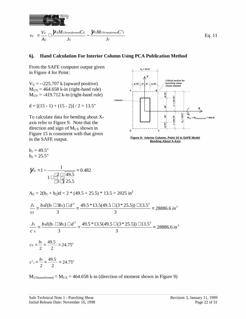
6j. Hand Calculation For Interior Column Using PCA Publication Method
From the SAFE computer output givenin Figure 4 for Point:
VU = --225.707 k (upward positive)MUX = 464.658 k-in (right-hand rule)MUY = -419.712 k-in (right-hand rule)
d = [(15 - 1) + (15 - 2)] / 2 = 13.5"
To calculate data for bending about X-axis refer to Figure 9. Note that thedirection and sign of MUX shown inFigure 15 is consistent with that givenin the SAFE output.
b1 = 49.5"b2 = 25.5"
482.0
5.25
5.49
3
21
11 =
+
−=VXγ
AC = 2(b1 + b2)d = 2 * (49.5 + 25.5) * 13.5 = 2025 in2
333
2116.28886
3
5.13))5.25*3(5.49(5.13*5.49
3
)3(in
dbbdb
c
J
X
X =++=++=
333
2116.28886
3
5.13))5.25*3(5.49(5.13*5.49
3
)3(
’in
dbbdb
c
J
X
X =++=++=
"75.242
5.49
2
1 === bcX
"75.242
5.49
2’
1 === bc x
MUXtransformed = MUX = 464.658 k-in (direction of moment shown in Figure 9)
6.75
"18
"18
"6.
75"
6" 6" 6.75"6.75"
X
Y
Figure 9: Interior Column, Point 10 in SAFE ModelBending About X-Axis
b1
= 49
.5"
b2 = 25.5"
Critical section forpunching shearshown dashed
A B
C
Column
c =2
4.75
"c’
= 2
4.75
"
MUX = MUXtransformed = 464.65
D
Safe Technical Note 1 - Punching Shear Revision 3, January 11, 1999Initial Release Date: November 16, 1998 Page 23 of 31
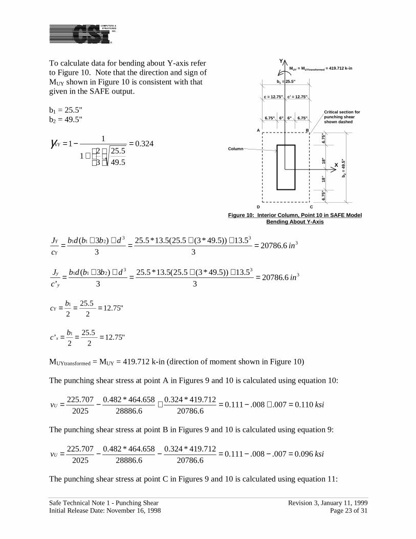
To calculate data for bending about Y-axis referto Figure 10. Note that the direction and sign ofMUY shown in Figure 10 is consistent with thatgiven in the SAFE output.
b1 = 25.5"b2 = 49.5"
324.0
5.49
5.25
3
21
11 =
+
−=VYγ
333
2116.20786
3
5.13))5.49*3(5.25(5.13*5.25
3
)3(in
dbbdb
c
J
Y
Y =++=++=
333
2116.20786
3
5.13))5.49*3(5.25(5.13*5.25
3
)3(
’in
dbbdb
c
J
y
y =++=++=
"75.122
5.25
2
1 === bcY
"75.122
5.25
2’
1 === bc x
MUYtransformed = MUY = 419.712 k-in (direction of moment shown in Figure 10)
The punching shear stress at point A in Figures 9 and 10 is calculated using equation 10:
ksivU 110.0007.008.111.06.20786
712.419*324.0
6.28886
658.464*482.0
2025
707.225 =+−=+−=
The punching shear stress at point B in Figures 9 and 10 is calculated using equation 9:
ksivU 096.0007.008.111.06.20786
712.419*324.0
6.28886
658.464*482.0
2025
707.225 =−−=−−=
The punching shear stress at point C in Figures 9 and 10 is calculated using equation 11:
6.75
"18
"18
"6.
75"
6" 6" 6.75"6.75"
X
Y
Figure 10: Interior Column, Point 10 in SAFE ModelBending About Y-Axis
b2 =
49.
5"
b1 = 25.5"
Critical section forpunching shearshown dashed
A B
C
Column
MUY = MUYtransformed = 419.712 k-in
c’ = 12.75"c = 12.75"
D
Safe Technical Note 1 - Punching Shear Revision 3, January 11, 1999Initial Release Date: November 16, 1998 Page 24 of 31
ksivU 112.0007.008.111.06.20786
712.419*324.0
6.28886
658.464*482.0
2025
707.225 =−+=−+=
The punching shear stress at point D in Figures 9 and 10 is calculated using equation 8:
ksivU 126.0007.008.111.06.20786
712.419*324.0
6.28886
658.464*482.0
2025
707.225 =++=++=
Point D has the largest absolute value of vu, thus vmax = 0.126 ksi
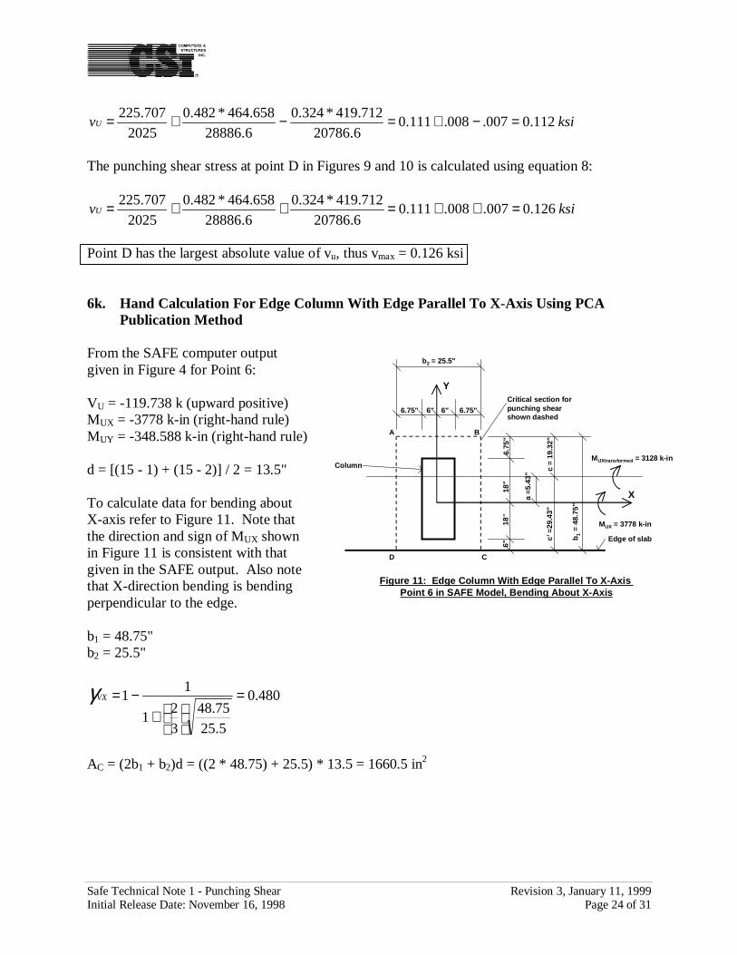
6k. Hand Calculation For Edge Column With Edge Parallel To X-Axis Using PCAPublication Method
From the SAFE computer outputgiven in Figure 4 for Point 6:
VU = -119.738 k (upward positive)MUX = -3778 k-in (right-hand rule)MUY = -348.588 k-in (right-hand rule)
d = [(15 - 1) + (15 - 2)] / 2 = 13.5"
To calculate data for bending aboutX-axis refer to Figure 11. Note thatthe direction and sign of MUX shownin Figure 11 is consistent with thatgiven in the SAFE output. Also notethat X-direction bending is bendingperpendicular to the edge.
b1 = 48.75"b2 = 25.5"
480.0
5.25
75.48
3
21
11 =
+
−=VXγ
AC = (2b1 + b2)d = ((2 * 48.75) + 25.5) * 13.5 = 1660.5 in2
6"18
"18
"6.
75"
6" 6" 6.75"6.75"
X
Y
Figure 11: Edge Column With Edge Parallel To X-Axis Point 6 in SAFE Model, Bending About X-Axis
b 1 =
48.
75"
b2 = 25.5"
Critical section forpunching shearshown dashed
B
C
Column
Edge of slabc’ =
29.4
3"c
= 19
.32"
MUX = 3778 k-in
MUXtransformed = 3128 k-in
a =5
.43"
A
D
Safe Technical Note 1 - Punching Shear Revision 3, January 11, 1999Initial Release Date: November 16, 1998 Page 25 of 31
332
1
213
212
1
3.2291775.48*6
)5.25)75.48*2((5.13))5.25*2(75.48(5.13*75.48*2
6
)2()2(2
in
b
bbdbbdb
c
J
X
X
=+++
=+++=
332
21
213
212
1
7.15046)5.2575.48(*6
)5.25)75.48*2((5.13))5.25*2(75.48(5.13*75.48*2
)(6
)2()2(2
’
in
bb
bbdbbdb
c
J
X
X
=+
+++
=+
+++=
"32.195.25)75.48*2(
75.48
2
2
21
21 =
+=
+=
bb
bcX
"43.295.25)75.48*2(
)5.2575.48(*75.48
)2
)(’
21
211 =++=
++=
bb
bbbc x
aX = 18 + 6.75 - 19.32 = 5.43"
MUXtransformed = 3778 - 119.738 * 5.43 = 3128 k-in (direction of moment shown in Figure 11)
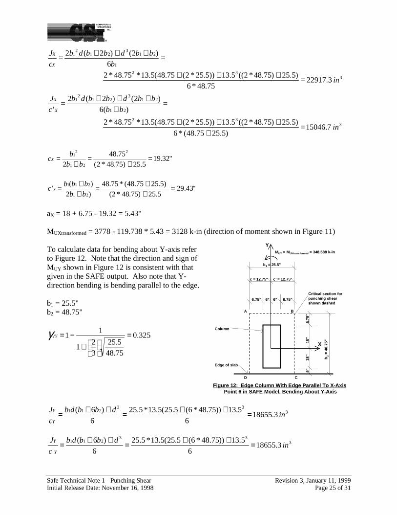
To calculate data for bending about Y-axis referto Figure 12. Note that the direction and sign ofMUY shown in Figure 12 is consistent with thatgiven in the SAFE output. Also note that Y-direction bending is bending parallel to the edge.
b1 = 25.5"b2 = 48.75"
325.0
75.48
5.25
3
21
11 =
+
−=VYγ
333
2113.18655
6
5.13))75.48*6(5.25(5.13*5.25
6
)6(in
dbbdb
c
J
Y
Y =++=++=
333
2113.18655
6
5.13))75.48*6(5.25(5.13*5.25
6
)6(
’in
dbbdb
c
J
Y
Y =++=++=
6"18
"18
"6.
75"
6" 6" 6.75"6.75"
X
Y
Figure 12: Edge Column With Edge Parallel To X-AxisPoint 6 in SAFE Model, Bending About Y-Axis
b2
= 4
8.75
"
b1 = 25.5"
Critical section forpunching shearshown dashed
A B
C
Column
Edge of slab
MUY = MUYtransformed = 348.588 k-in
c’ = 12.75"c = 12.75"
D
Safe Technical Note 1 - Punching Shear Revision 3, January 11, 1999Initial Release Date: November 16, 1998 Page 26 of 31
"75.122
5.25
2
1 === bcY
"75.122
5.25
2’
1 === bc Y
MUYtransformed = MUY = 348.588 k-in (direction of moment shown in Figure 12)
The punching shear stress at point A in Figures 11 and 12 is calculated using equation 8:
ksivU 144.0006.066.072.03.18655
588.348*325.0
3.22917
3128*480.0
5.1660
738.119 =++=++=
The punching shear stress at point B in Figures 11 and 12 is calculated using equation 11:
ksivU 132.0006.066.072.03.18655
588.348*325.0
3.22917
3128*480.0
5.1660
738.119 =−+=−+=
The punching shear stress at point C in Figures 11 and 12 is calculated using equation 9:
ksivU 034.0006.100.072.03.18655
588.348*325.0
7.15046
3128*480.0
5.1660
738.119 −=−−=−−=
The punching shear stress at point D in Figures 11 and 12 is calculated using equation 10:
ksivU 022.0006.100.072.03.18655
588.348*325.0
7.15046
3128*480.0
5.1660
738.119 −=+−=+−=
Point A has the largest absolute value of vu, thus vmax = 0.144 ksi
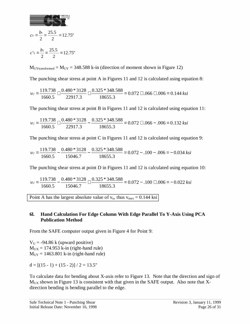
6l. Hand Calculation For Edge Column With Edge Parallel To Y-Axis Using PCAPublication Method
From the SAFE computer output given in Figure 4 for Point 9:
VU = -94.86 k (upward positive)MUX = 174.953 k-in (right-hand rule)MUY = 1463.801 k-in (right-hand rule)
d = [(15 - 1) + (15 - 2)] / 2 = 13.5"
To calculate data for bending about X-axis refer to Figure 13. Note that the direction and sign ofMUX shown in Figure 13 is consistent with that given in the SAFE output. Also note that X-direction bending is bending parallel to the edge.
Safe Technical Note 1 - Punching Shear Revision 3, January 11, 1999Initial Release Date: November 16, 1998 Page 27 of 31
b1 = 49.5"b2 = 24.75"
485.0
75.24
5.49
3
21
11 =
+
−=VXγ
AC = (b1 + 2b2)d= (49.5 + (2 * 24.75)) * 13.5= 1336.5 in2
333
2113.22462
6
5.13))75.24*6(5.49(5.13*5.49
6
)6(in
dbbdb
c
J
X
X =++=++=
333
2113.22462
6
5.13))75.24*6(5.49(5.13*5.49
6
)6(
’in
dbbdb
c
J
X
X =++=++=
"75.242
5.49
2
1 === bcX
"75.242
5.49
2’
1 === bc X
MUXtransformed = MUX = 174.953 k-in (direction ofmoment shown in Figure 13)
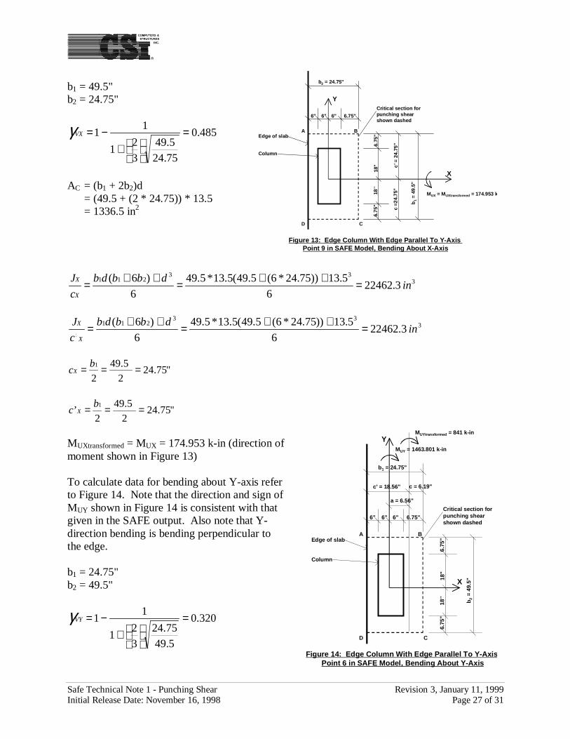
To calculate data for bending about Y-axis referto Figure 14. Note that the direction and sign ofMUY shown in Figure 14 is consistent with thatgiven in the SAFE output. Also note that Y-direction bending is bending perpendicular tothe edge.
b1 = 24.75"b2 = 49.5"
320.0
5.49
75.24
3
21
11 =
+
−=VYγ
6.75
"18
"18
"6.
75"
6" 6" 6.75"6"
X
Y
Figure 13: Edge Column With Edge Parallel To Y-Axis Point 9 in SAFE Model, Bending About X-Axis
b1
= 49
.5"
b2 = 24.75"
Critical section forpunching shearshown dashed
A B
C
Column
Edge of slab
c =2
4.75
"c’
= 2
4.75
"
MUX = MUXtransformed = 174.953 k
D
C
6.75
"18
"18
"6.
75"
6" 6" 6.75"6"
X
Y
Figure 14: Edge Column With Edge Parallel To Y-AxisPoint 6 in SAFE Model, Bending About Y-Axis
b2 =
49.
5"b1 = 24.75"
Critical section forpunching shearshown dashed
A B
Column
Edge of slab
MUY = 1463.801 k-in
c = 6.19"c’ = 18.56"
MUYtransformed = 841 k-in
a = 6.56"
D
Safe Technical Note 1 - Punching Shear Revision 3, January 11, 1999Initial Release Date: November 16, 1998 Page 28 of 31
332
1
213
212
1
9.1542275.24*6
)5.49)75.24*2((5.13))5.49*2(75.24(5.13*75.24*2
6
)2()2(2
in
b
bbdbbdb
c
J
Y
Y
=+++
=+++=
332
21
213
212
1
0.5141)5.4975.24(*6
)5.49)75.24*2((5.13))5.49*2(75.24(5.13*75.24*2
)(6
)2()2(2
’
in
bb
bbdbbdb
c
J
Y
Y
=+
+++
=+
+++=
"19.65.49)75.24*2(
75.24
2
2
21
21 =
+=
+=
bb
bcY
"56.185.49)75.24*2(
)5.4975.24(*75.24
)2
)(’
21
211 =++=
++=bb
bbbc Y
aY = 6 + 6.75 - 6.19 = 6.56"
MUYtransformed = 1463.801 - 94.86 * 6.56 = 841 k-in (direction of moment shown in Figure 14)
The punching shear stress at point A in Figures 13 and 14 is calculated using equation 9:
ksivU 015.0052.004.071.00.5141
841*320.0
3.22462
953.174*485.0
5.1336
86.94 =−−=−−=
The punching shear stress at point B in Figures 13 and 14 is calculated using equation 10:
ksivU 084.0017.004.071.09.15422
841*320.0
3.22462
953.174*485.0
5.1336
86.94 =+−=+−=
The punching shear stress at point C in Figures 13 and 14 is calculated using equation 8:
ksivU 092.0017.004.071.09.15422
841*320.0
3.22462
953.174*485.0
5.1336
86.94 =++=++=
The punching shear stress at point D in Figures 13 and 14 is calculated using equation 11:
ksivU 023.0052.004.071.00.5141
841*320.0
3.22462
953.174*485.0
5.1336
86.94 =−+=−+=
Point C has the largest absolute value of vu, thus vmax = 0.092 ksi
Safe Technical Note 1 - Punching Shear Revision 3, January 11, 1999Initial Release Date: November 16, 1998 Page 29 of 31
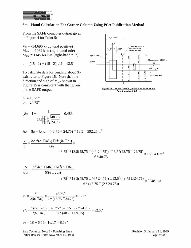
6m. Hand Calculation For Corner Column Using PCA Publication Method
From the SAFE computer output givenin Figure 4 for Point 5:
VU = -54.696 k (upward positive)MUX = -1962 k-in (right-hand rule)MUY = 1145.68 k-in (right-hand rule)
d = [(15 - 1) + (15 - 2)] / 2 = 13.5"
To calculate data for bending about X-axis refer to Figure 15. Note that thedirection and sign of MUX shown inFigure 15 is consistent with that givenin the SAFE output.
b1 = 48.75"b2 = 24.75"
483.0
75.24
75.48
3
21
11 =
+
−=VXγ
AC = (b1 + b2)d = (48.75 + 24.75) * 13.5 = 992.25 in2
332
1
213
212
1
6.1682475.48*6
)75.2475.48(5.13))75.24*4(75.48(5.13*75.48
6
)()4(
in
b
bbdbbdb
c
J
X
X
=+++
=+++=
332
21
213
212
1
1.8348))75.24*2(75.48(*6
)75.2475.48(5.13))75.24*4(75.48(5.13*75.48
)2(6
)()4(
’
in
bb
bbdbbdb
c
J
X
X
=+
+++
=+
+++=
"17.16)75.2475.48(*2
75.48
)(2
2
21
21 =
+=
+=
bb
bcX
"58.32)75.2475.48(*2
)75.24*2(75.48(*75.48
)(2
)2(’
21
211 =++=
++=
bb
bbbc x
aX = 18 + 6.75 - 16.17 = 8.58"
6"18
"18
"6.
75"
6" 6" 6.75"6"
X
Y
Figure 15: Corner Column, Point 5 in SAFE ModelBending About X-Axis
b1
= 48
.75"
b2 = 24.75"
Critical section forpunching shearshown dashed
A B
C
Column
Edge of slab
c’ =
32.5
8"c
= 16
.17"
MUX = 1962 k-in
MUXtransformed = 1493 k-in
a =8
.58"
Safe Technical Note 1 - Punching Shear Revision 3, January 11, 1999Initial Release Date: November 16, 1998 Page 30 of 31
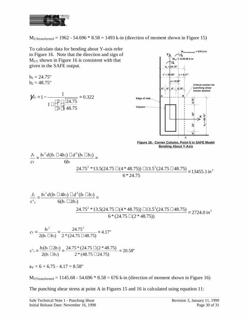
MUXtransformed = 1962 - 54.696 * 8.58 = 1493 k-in (direction of moment shown in Figure 15)
To calculate data for bending about Y-axis referto Figure 16. Note that the direction and sign ofMUY shown in Figure 16 is consistent with thatgiven in the SAFE output.
b1 = 24.75"b2 = 48.75"
322.0
75.48
75.24
3
21
11 =
+
−=VYγ
332
1
213
212
1
1.1345575.24*6
)75.4875.24(5.13))75.48*4(75.24(5.13*75.24
6
)()4(
in
b
bbdbbdb
c
J
Y
Y
=+++
=+++=
332
21
213
212
1
0.2724))75.48*2(75.24(*6
)75.4875.24(5.13))75.48*4(75.24(5.13*75.24
)2(6
)()4(
’
in
bb
bbdbbdb
c
J
y
y
=+
+++
=+
+++=
"17.4)75.4875.24(*2
75.24
)(2
2
21
21 =
+=
+=
bb
bcY
"58.20)75.2475.48(*2
)75.48*2(75.24(*75.24
)(2
)2(’
21
211 =++=
++=
bb
bbbc x
aY = 6 + 6.75 - 4.17 = 8.58"
MUYtransformed = 1145.68 - 54.696 * 8.58 = 676 k-in (direction of moment shown in Figure 16)
The punching shear stress at point A in Figures 15 and 16 is calculated using equation 11:
6"18
"18
"6.
75"
6" 6" 6.75"6"
X
Y
Figure 16: Corner Column, Point 5 in SAFE ModelBending About Y-Axis
b2 =
48.
75"
b1 = 24.75"
Critical section forpunching shearshown dashed
A B
C
Column
Edge of slab
MUY = 1145.68 k-in
c = 4.17"c’ = 20.58"
MUYtransformed = 676 k-in
a = 8.58"
Safe Technical Note 1 - Punching Shear Revision 3, January 11, 1999Initial Release Date: November 16, 1998 Page 31 of 31
ksivU 018.0080.043.055.00.2724
676*322.0
6.16824
1493*483.0
25.992
696.54 =−+=−+=
The punching shear stress at point B in Figures 15 and 16 is calculated using equation 8:
ksivU 114.0016.043.055.01.13455
676*322.0
6.16824
1493*483.0
25.992
696.54 =++=++=
The punching shear stress at point C in Figures 15 and 16 is calculated using equation 10:
ksivU 018.0016.086.055.00.2724
676*322.0
1.8348
1493*483.0
25.992
696.54 −=+−=+−=
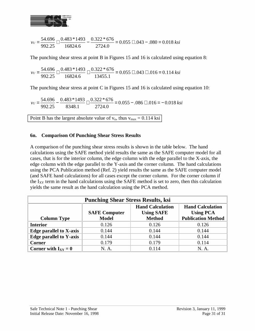
Point B has the largest absolute value of vu, thus vmax = 0.114 ksi
6n. Comparison Of Punching Shear Stress Results
A comparison of the punching shear stress results is shown in the table below. The handcalculations using the SAFE method yield results the same as the SAFE computer model for allcases, that is for the interior column, the edge column with the edge parallel to the X-axis, theedge column with the edge parallel to the Y-axis and the corner column. The hand calculationsusing the PCA Publication method (Ref. 2) yield results the same as the SAFE computer model(and SAFE hand calculations) for all cases except the corner column. For the corner column ifthe IXY term in the hand calculations using the SAFE method is set to zero, then this calculationyields the same result as the hand calculation using the PCA method.
Punching Shear Stress Results, ksi
Column TypeSAFE Computer
Model
Hand CalculationUsing SAFE
Method
Hand CalculationUsing PCA
Publication MethodInterior 0.126 0.126 0.126Edge parallel to X-axis 0.144 0.144 0.144Edge parallel to Y-axis 0.144 0.144 0.144Corner 0.179 0.179 0.114Corner with IXY = 0 N. A. 0.114 N. A.