Embed Size (px)
Citation preview
Design and performance
analysis of a Tram-Train
profile for dual operation
running
Crosbee D. & Allen P.D.
University of Huddersfield, United Kingdom
Carroll R.
Stagecoach Supertram
ABSTRACT
This paper explores the design of a new wheel profile for use
on a Tram-Train vehicle. A Tram-Train is a dual-mode vehicle
that operates on two very different railway infrastructures; as a
tram on light rail infrastructure and as a conventional train on
heavy rail infrastructure.
The wheel/rail interface challenges have been highlighted and
discussed and the analysis and design process required to
develop an optimised wheel profile for dual operation running
has been presented.
One of the key issues in developing a dual-operation wheel
profile was managing the contact conditions within the
wheel/rail interface. The interface is critical not only to the
safe running of the vehicle but also to maximise asset life and
to minimise wheel-rail damage. A combination of vehicle
dynamic simulations and bespoke software were used to allow
the development of a new wheel profile for Tram-Train
operations.
Keywords
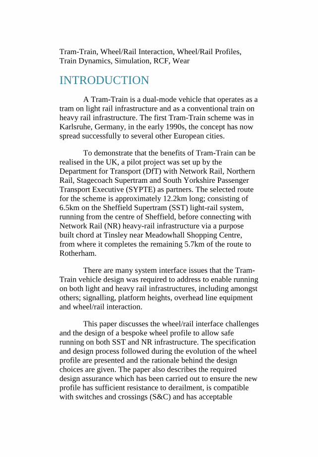
Tram-Train, Wheel/Rail Interaction, Wheel/Rail Profiles,
Train Dynamics, Simulation, RCF, Wear
INTRODUCTION
A Tram-Train is a dual-mode vehicle that operates as a
tram on light rail infrastructure and as a conventional train on
heavy rail infrastructure. The first Tram-Train scheme was in
Karlsruhe, Germany, in the early 1990s, the concept has now
spread successfully to several other European cities.
To demonstrate that the benefits of Tram-Train can be
realised in the UK, a pilot project was set up by the
Department for Transport (DfT) with Network Rail, Northern
Rail, Stagecoach Supertram and South Yorkshire Passenger
Transport Executive (SYPTE) as partners. The selected route
for the scheme is approximately 12.2km long; consisting of
6.5km on the Sheffield Supertram (SST) light-rail system,
running from the centre of Sheffield, before connecting with
Network Rail (NR) heavy-rail infrastructure via a purpose
built chord at Tinsley near Meadowhall Shopping Centre,
from where it completes the remaining 5.7km of the route to
Rotherham.
There are many system interface issues that the Tram-
Train vehicle design was required to address to enable running
on both light and heavy rail infrastructures, including amongst
others; signalling, platform heights, overhead line equipment
and wheel/rail interaction.
This paper discusses the wheel/rail interface challenges
and the design of a bespoke wheel profile to allow safe
running on both SST and NR infrastructure. The specification
and design process followed during the evolution of the wheel
profile are presented and the rationale behind the design
choices are given. The paper also describes the required
design assurance which has been carried out to ensure the new
profile has sufficient resistance to derailment, is compatible
with switches and crossings (S&C) and has acceptable
performance in terms of wheel-rail rolling contact fatigue and
wear.
Interface Challenges
Wheel profiles are normally designed or selected to be
compatible with the rail profiles and track construction used
on a particular system. As a result of this, the existing wheel
profiles used on SST and NR are very different when
compared to one another; Figure 1 shows the two profiles and
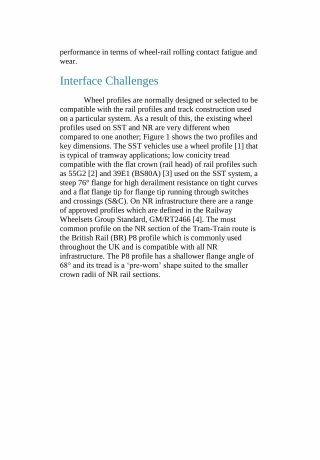
key dimensions. The SST vehicles use a wheel profile [1] that
is typical of tramway applications; low conicity tread
compatible with the flat crown (rail head) of rail profiles such
as 55G2 [2] and 39E1 (BS80A) [3] used on the SST system, a
steep 76° flange for high derailment resistance on tight curves
and a flat flange tip for flange tip running through switches
and crossings (S&C). On NR infrastructure there are a range
of approved profiles which are defined in the Railway
Wheelsets Group Standard, GM/RT2466 [4]. The most
common profile on the NR section of the Tram-Train route is
the British Rail (BR) P8 profile which is commonly used
throughout the UK and is compatible with all NR
infrastructure. The P8 profile has a shallower flange angle of
68° and its tread is a ‘pre-worn’ shape suited to the smaller
crown radii of NR rail sections.
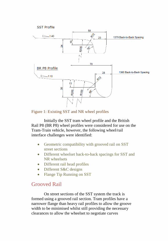
Figure 1: Existing SST and NR wheel profiles
Initially the SST tram wheel profile and the British
Rail P8 (BR P8) wheel profiles were considered for use on the
Tram-Train vehicle, however, the following wheel/rail
interface challenges were identified:
Geometric compatibility with grooved rail on SST
street sections
Different wheelset back-to-back spacings for SST and
NR wheelsets
Different rail head profiles
Different S&C designs
Flange Tip Running on SST
Grooved Rail
On street sections of the SST system the track is
formed using a grooved rail section. Tram profiles have a
narrower flange than heavy rail profiles to allow the groove
width to be minimised whilst still providing the necessary
clearances to allow the wheelset to negotiate curves
effectively. NR wheel profiles, such as the BR P8, are not
suitable for use on SST infrastructure as the wider flange
leaves insufficient flangeback clearance to the keeper rail to
allow the wheelset to steer effectively in curves. Figure 2
shows an SST and a BR P8 wheel profile on a grooved rail
section.
Figure 2: Wheel Profiles on Grooved Rail
Back-to-Back Spacing
When negotiating Switches and Crossings (S&C) the
wheelset is guided through the acute crossing nose by a check
rail contacting on the opposite wheel’s flangeback. The check
rail prevents the flange tip from striking the crossing nose or
the wheel taking the wrong route all together. The back-to-
back spacing of the wheelset is therefore a critical dimension.
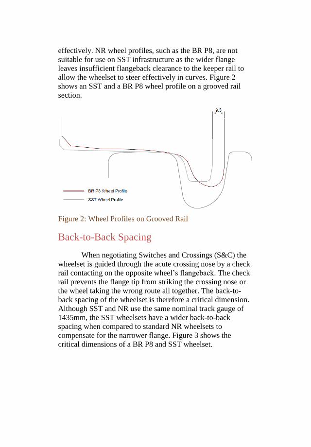
Although SST and NR use the same nominal track gauge of
1435mm, the SST wheelsets have a wider back-to-back
spacing when compared to standard NR wheelsets to
compensate for the narrower flange. Figure 3 shows the
critical dimensions of a BR P8 and SST wheelset.
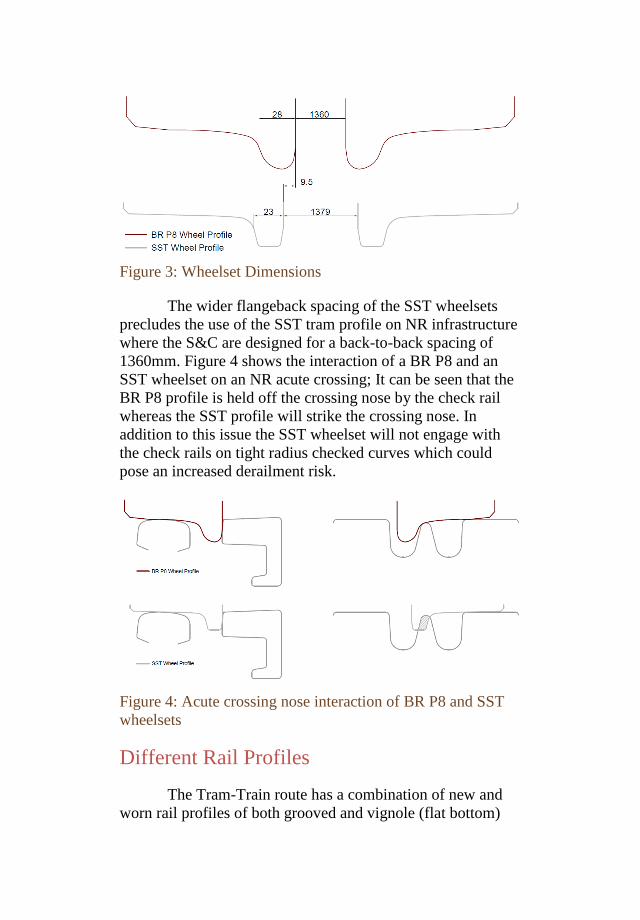
Figure 3: Wheelset Dimensions
The wider flangeback spacing of the SST wheelsets
precludes the use of the SST tram profile on NR infrastructure
where the S&C are designed for a back-to-back spacing of
1360mm. Figure 4 shows the interaction of a BR P8 and an
SST wheelset on an NR acute crossing; It can be seen that the
BR P8 profile is held off the crossing nose by the check rail
whereas the SST profile will strike the crossing nose. In
addition to this issue the SST wheelset will not engage with
the check rails on tight radius checked curves which could
pose an increased derailment risk.
Figure 4: Acute crossing nose interaction of BR P8 and SST
wheelsets
Different Rail Profiles
The Tram-Train route has a combination of new and
worn rail profiles of both grooved and vignole (flat bottom)
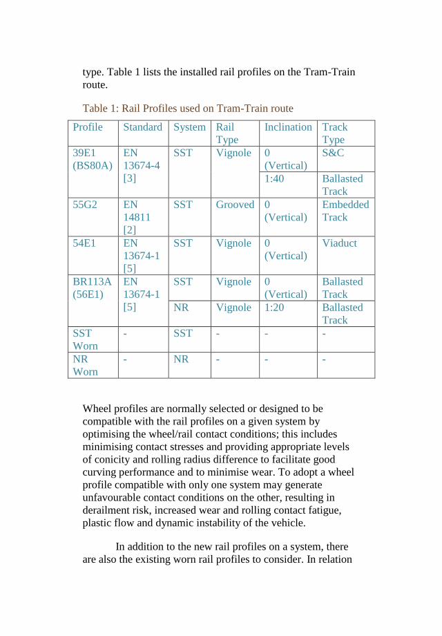
type. Table 1 lists the installed rail profiles on the Tram-Train
route.
Table 1: Rail Profiles used on Tram-Train route
Profile Standard System Rail
Type
Inclination Track
Type
39E1
(BS80A)
EN
13674-4
[3]
SST Vignole 0
(Vertical)
S&C
1:40 Ballasted
Track
55G2 EN
14811
[2]
SST Grooved 0
(Vertical)
Embedded
Track
54E1 EN
13674-1
[5]
SST Vignole 0
(Vertical)
Viaduct
BR113A
(56E1)
EN
13674-1
[5]
SST Vignole 0
(Vertical)
Ballasted
Track
NR Vignole 1:20 Ballasted
Track
SST
Worn
- SST - - -
NR
Worn
- NR - - -
Wheel profiles are normally selected or designed to be
compatible with the rail profiles on a given system by
optimising the wheel/rail contact conditions; this includes
minimising contact stresses and providing appropriate levels
of conicity and rolling radius difference to facilitate good
curving performance and to minimise wear. To adopt a wheel
profile compatible with only one system may generate
unfavourable contact conditions on the other, resulting in
derailment risk, increased wear and rolling contact fatigue,
plastic flow and dynamic instability of the vehicle.
In addition to the new rail profiles on a system, there
are also the existing worn rail profiles to consider. In relation
to wheel/rail contact conditions it was found that measured
worn rail profiles of 39E1 and 55G2 from SST had the same
shape and therefore only one worn rail profile for SST needed
to be considered [6]. It was also found that NR rails tended to
wear to the same shape, that of a P8 wheel, so similarly only
one worn NR rail profile was considered. The high rails on
curves of different radii tend to wear to the same shape over
time but at different rates, it was therefore possible to consider
one worn profile shape as a worst case for all curve radii. On
tangent track and low rails in curves the wheel tread will be in
contact with the rail head resulting in low contact stresses; The
lower stresses mean that wear rates tend to be much less than
for the high rail so this case has been neglected.
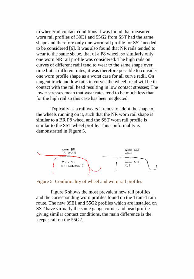
Typically as a rail wears it tends to adopt the shape of
the wheels running on it, such that the NR worn rail shape is
similar to a BR P8 wheel and the SST worn rail profile is
similar to the SST wheel profile. This conformality is
demonstrated in Figure 5.
Figure 5: Conformality of wheel and worn rail profiles
Figure 6 shows the most prevalent new rail profiles
and the corresponding worn profiles found on the Tram-Train
route. The new 39E1 and 55G2 profiles which are installed on
SST have virtually the same gauge corner and head profile
giving similar contact conditions, the main difference is the
keeper rail on the 55G2.
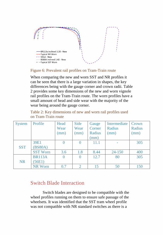
Figure 6: Prevalent rail profiles on Tram-Train route
When comparing the new and worn SST and NR profiles it
can be seen that there is a large variation in shapes, the key
differences being with the gauge corner and crown radii. Table
2 provides some key dimensions of the new and worn vignole
rail profiles on the Tram-Train route. The worn profiles have a
small amount of head and side wear with the majority of the
wear being around the gauge corner.
Table 2: Key dimensions of new and worn rail profiles used
on Tram-Train route
System Profile Head
Wear
(mm)
Side
Wear
(mm)
Gauge
Corner
Radius
(mm)
Intermediate
Radius
(mm)
Crown
Radius
(mm)
SST
39E1
(BS80A)
0 0 11.1 - 305
SST Worn 3.6 1.8 8.44 24-150 400
NR
BR113A
(56E1)
0 0 12.7 80 305
NR Worn 0.7 2 15 50 150
Switch Blade Interaction
Switch blades are designed to be compatible with the
wheel profiles running on them to ensure safe passage of the
wheelsets. It was identified that the SST tram wheel profile
was not compatible with NR standard switches as there is a
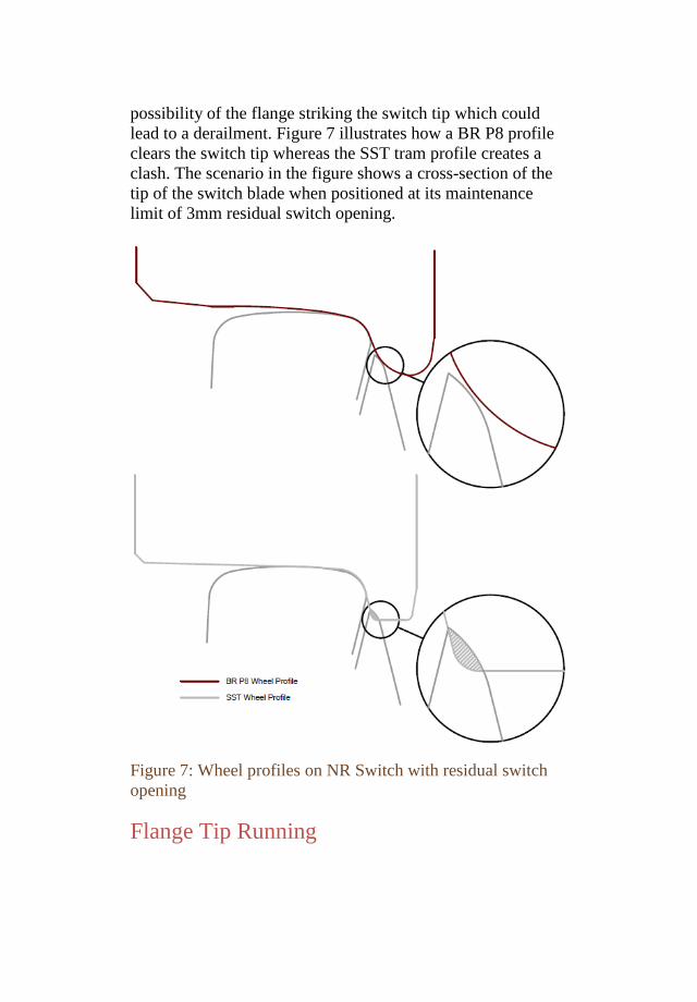
possibility of the flange striking the switch tip which could
lead to a derailment. Figure 7 illustrates how a BR P8 profile
clears the switch tip whereas the SST tram profile creates a
clash. The scenario in the figure shows a cross-section of the
tip of the switch blade when positioned at its maintenance
limit of 3mm residual switch opening.
Figure 7: Wheel profiles on NR Switch with residual switch
opening
Flange Tip Running
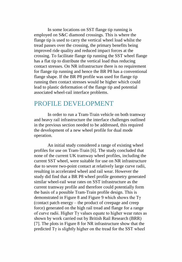
In some locations on SST flange tip running is
employed on S&C diamond crossings. This is where the
flange tip is used to carry the vertical wheel load whilst the
tread passes over the crossing, the primary benefits being
improved ride quality and reduced impact forces at the
crossing. To facilitate flange tip running the SST wheel flange
has a flat tip to distribute the vertical load thus reducing
contact stresses. On NR infrastructure there is no requirement
for flange tip running and hence the BR P8 has a conventional
flange shape. If the BR P8 profile was used for flange tip
running then contact stresses would be higher which could
lead to plastic deformation of the flange tip and potential
associated wheel-rail interface problems.
PROFILE DEVELOPMENT
In order to run a Tram-Train vehicle on both tramway
and heavy rail infrastructure the interface challenges outlined
in the previous section needed to be addressed, this required
the development of a new wheel profile for dual mode
operation.
An initial study considered a range of existing wheel
profiles for use on Tram-Train [6]. The study concluded that
none of the current UK tramway wheel profiles, including the
current SST wheel, were suitable for use on NR infrastructure
due to severe two-point contact at relatively large curve radii,
resulting in accelerated wheel and rail wear. However the
study did find that a BR P8 wheel profile geometry generated
similar wheel-rail wear rates on SST infrastructure as the
current tramway profile and therefore could potentially form
the basis of a possible Tram-Train profile design. This is
demonstrated in Figure 8 and Figure 9 which shows the Tγ
(contact patch energy – the product of creepage and creep
force) generated on the high rail tread and flange for a range
of curve radii. Higher Tγ values equate to higher wear rates as
shown by work carried out by British Rail Research (BRR)
[7]. The plots in Figure 8 for NR infrastructure show that the
predicted Tγ is slightly higher on the tread for the SST wheel
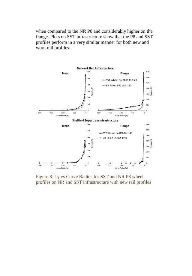
when compared to the NR P8 and considerably higher on the
flange. Plots on SST infrastructure show that the P8 and SST
profiles perform in a very similar manner for both new and
worn rail profiles.
Figure 8: Tγ vs Curve Radius for SST and NR P8 wheel
profiles on NR and SST infrastructure with new rail profiles
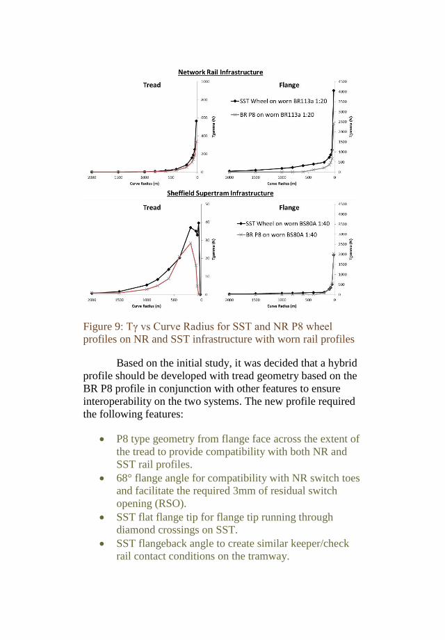
Figure 9: Tγ vs Curve Radius for SST and NR P8 wheel
profiles on NR and SST infrastructure with worn rail profiles
Based on the initial study, it was decided that a hybrid
profile should be developed with tread geometry based on the
BR P8 profile in conjunction with other features to ensure
interoperability on the two systems. The new profile required
the following features:
P8 type geometry from flange face across the extent of
the tread to provide compatibility with both NR and
SST rail profiles.
68° flange angle for compatibility with NR switch toes
and facilitate the required 3mm of residual switch
opening (RSO).
SST flat flange tip for flange tip running through
diamond crossings on SST.
SST flangeback angle to create similar keeper/check
rail contact conditions on the tramway.
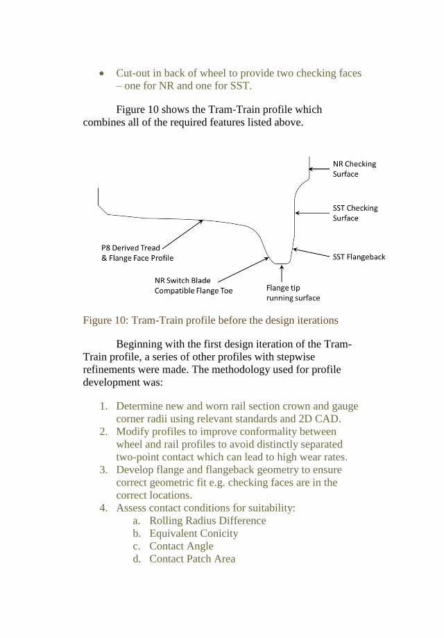
Cut-out in back of wheel to provide two checking faces
– one for NR and one for SST.
Figure 10 shows the Tram-Train profile which
combines all of the required features listed above.
Figure 10: Tram-Train profile before the design iterations
Beginning with the first design iteration of the Tram-
Train profile, a series of other profiles with stepwise
refinements were made. The methodology used for profile
development was:
1. Determine new and worn rail section crown and gauge
corner radii using relevant standards and 2D CAD.
2. Modify profiles to improve conformality between
wheel and rail profiles to avoid distinctly separated
two-point contact which can lead to high wear rates.
3. Develop flange and flangeback geometry to ensure
correct geometric fit e.g. checking faces are in the
correct locations.
4. Assess contact conditions for suitability:
a. Rolling Radius Difference
b. Equivalent Conicity
c. Contact Angle
d. Contact Patch Area
5. Dynamic simulations to assess curving performance in
terms of Tγ and Contact Stress.
6. Review design and repeat as necessary.
A total of 7 different profiles were developed and
assessed. The profile design which met all of the geometric
requirements and provided the best overall performance on
SST and NR infrastructure was selected as the final design. It
is this final iteration which forms the basis of the analysis
within this paper.
Contact Conditions
For each developed wheel profile a set of contact data
was generated using each of the rail profiles found on the
Tram-Train route. The contact data was created using the
Contact Data Generation program within the VAMPIRE®
vehicle dynamics simulation software [8]. The data contains
information describing the geometric contact conditions
between wheel and rail for a series of lateral positions of the
wheelset relative to the rail. Contact data was calculated using
the nominal wheel diameter, nominal gauge and the laden
axleload for the Tram-Train vehicle. The parameters of
interest were rolling radius difference, contact angle and
contact patch area. The Contact Data Generation program also
calculates the equivalent conicity of the wheel rail
combination.
Each parameter was compared to the base cases of the
existing SST new and worn wheel profile on SST
infrastructure and a new and worn BR P8 wheel profiles on
NR infrastructure. The following subsections explain the
different contact data parameters and the results of analysis for
the proposed new Tram-Train wheel profile.
Rolling radius difference
Rolling radius difference (RRD) is the difference
between the wheel radii at the contact patches of the left and
right wheels. The RRD is the mechanism through which a
conventional wheelset self-steers on curves. The plotted RRD
curve provides an indication of the level of steering that a
wheel profile will generate as well as helping to identify if, or
at what lateral shift, two-point contact occurs. It is desirable to
develop a conformal wheel profile that avoids severe two-
point contact as this helps to prevent excessive Tγ levels and
high wheel-rail wear rates [9]. Two point contact with a large
difference in RRD between the two contacts results in an
imbalance of the longitudinal creep forces giving rise to higher
creepages and therefore wear. Developing a conformal profile
also delivers the benefit of distributing the contact patch, and
therefore wear, across the whole wheel and rail rather than
generating distinct bands of wear.
The desired RRD plot should therefore have a smooth
transition from tread to flange contact without significant
jumps (in the order of 10mm) which would indicate two-point
contact. In addition, the gradient of the RRD plot indicates the
conicity of the wheel/rail profile combination, with the
conicity being half of the gradient for a linear profile. The
conicity of the profile is important as a high conicity will
provide good curving performance but will make the vehicle
more susceptible to a lateral instability mode, also known as
hunting. Although good curving performance is desirable,
poor lateral stability should be avoided as it is detrimental to
passenger ride comfort and wheel-rail asset life. A low
conicity profile combination would have a conicity of around
0.05 whereas a high conicity profile combination could be 0.5
or higher.
Figure 11 shows the RRD plots for new and worn SST
wheel profiles and the new Tram-Train wheel profile on worn
SST rail. The new and worn SST wheel profiles provide little
RRD up to the point of flange contact, at which point the RRD
rises rapidly. The jump in the RRD for the worn SST profile
between 6 and 7mm lateral shift is due to the manner in which
the side worn rail profile interacts with the wheel flange
resulting in the contact patch jumping up and then back down
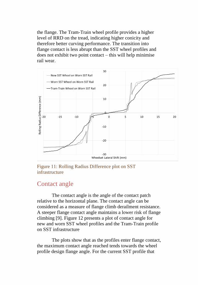
the flange. The Tram-Train wheel profile provides a higher
level of RRD on the tread, indicating higher conicity and
therefore better curving performance. The transition into
flange contact is less abrupt than the SST wheel profiles and
does not exhibit two point contact – this will help minimise
rail wear.
Figure 11: Rolling Radius Difference plot on SST
infrastructure
Contact angle
The contact angle is the angle of the contact patch
relative to the horizontal plane. The contact angle can be
considered as a measure of flange climb derailment resistance.
A steeper flange contact angle maintains a lower risk of flange
climbing [9]. Figure 12 presents a plot of contact angle for
new and worn SST wheel profiles and the Tram-Train profile
on SST infrastructure
The plots show that as the profiles enter flange contact,
the maximum contact angle reached tends towards the wheel
profile design flange angle. For the current SST profile that
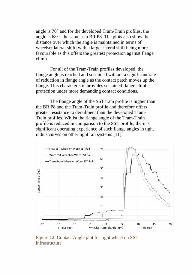
angle is 76° and for the developed Tram-Train profiles, the
angle is 68° - the same as a BR P8. The plots also show the
distance over which the angle is maintained in terms of
wheelset lateral shift, with a larger lateral shift being more
favourable as this offers the greatest protection against flange
climb.
For all of the Tram-Train profiles developed, the
flange angle is reached and sustained without a significant rate
of reduction in flange angle as the contact patch moves up the
flange. This characteristic provides sustained flange climb
protection under more demanding contact conditions.
The flange angle of the SST tram profile is higher than
the BR P8 and the Tram-Train profile and therefore offers
greater resistance to derailment than the developed Tram-
Train profiles. Whilst the flange angle of the Tram-Train
profile is reduced in comparison to the SST profile, there is
significant operating experience of such flange angles in tight
radius curves on other light rail systems [11].
Figure 12: Contact Angle plot for right wheel on SST
infrastructure
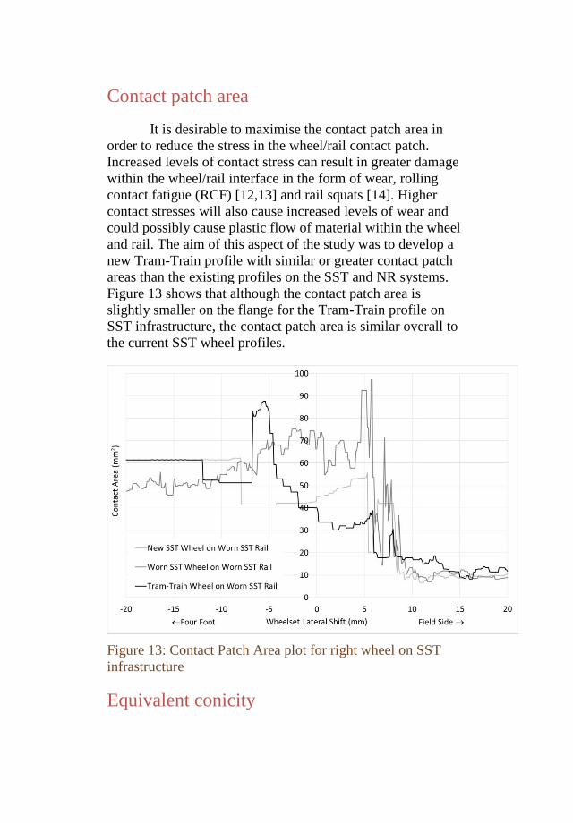
Contact patch area
It is desirable to maximise the contact patch area in
order to reduce the stress in the wheel/rail contact patch.
Increased levels of contact stress can result in greater damage
within the wheel/rail interface in the form of wear, rolling
contact fatigue (RCF) [12,13] and rail squats [14]. Higher
contact stresses will also cause increased levels of wear and
could possibly cause plastic flow of material within the wheel
and rail. The aim of this aspect of the study was to develop a
new Tram-Train profile with similar or greater contact patch
areas than the existing profiles on the SST and NR systems.
Figure 13 shows that although the contact patch area is
slightly smaller on the flange for the Tram-Train profile on
SST infrastructure, the contact patch area is similar overall to
the current SST wheel profiles.
Figure 13: Contact Patch Area plot for right wheel on SST
infrastructure
Equivalent conicity
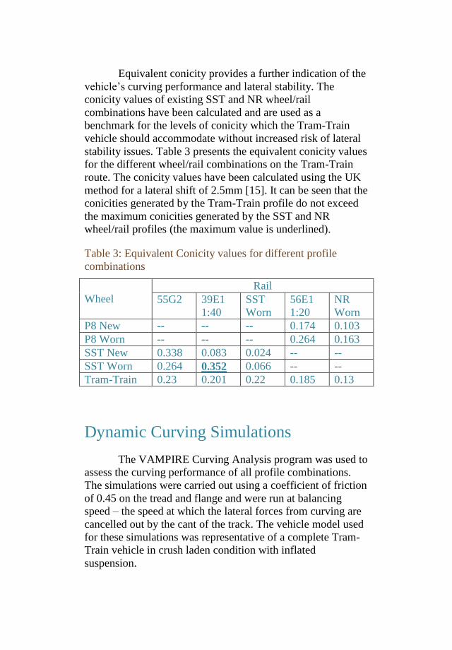
Equivalent conicity provides a further indication of the
vehicle’s curving performance and lateral stability. The
conicity values of existing SST and NR wheel/rail
combinations have been calculated and are used as a
benchmark for the levels of conicity which the Tram-Train
vehicle should accommodate without increased risk of lateral
stability issues. Table 3 presents the equivalent conicity values
for the different wheel/rail combinations on the Tram-Train
route. The conicity values have been calculated using the UK
method for a lateral shift of 2.5mm [15]. It can be seen that the
conicities generated by the Tram-Train profile do not exceed
the maximum conicities generated by the SST and NR
wheel/rail profiles (the maximum value is underlined).
Table 3: Equivalent Conicity values for different profile
combinations
Wheel
Rail
55G2 39E1
1:40
SST
Worn
56E1
1:20
NR
Worn
P8 New -- -- -- 0.174 0.103
P8 Worn -- -- -- 0.264 0.163
SST New 0.338 0.083 0.024 -- --
SST Worn 0.264 0.352 0.066 -- --
Tram-Train 0.23 0.201 0.22 0.185 0.13
Dynamic Curving Simulations
The VAMPIRE Curving Analysis program was used to
assess the curving performance of all profile combinations.
The simulations were carried out using a coefficient of friction
of 0.45 on the tread and flange and were run at balancing
speed – the speed at which the lateral forces from curving are
cancelled out by the cant of the track. The vehicle model used
for these simulations was representative of a complete Tram-
Train vehicle in crush laden condition with inflated
suspension.
The outputs from the simulations were the Tγ and the
Contact Stress in the tread and flange contact patches.
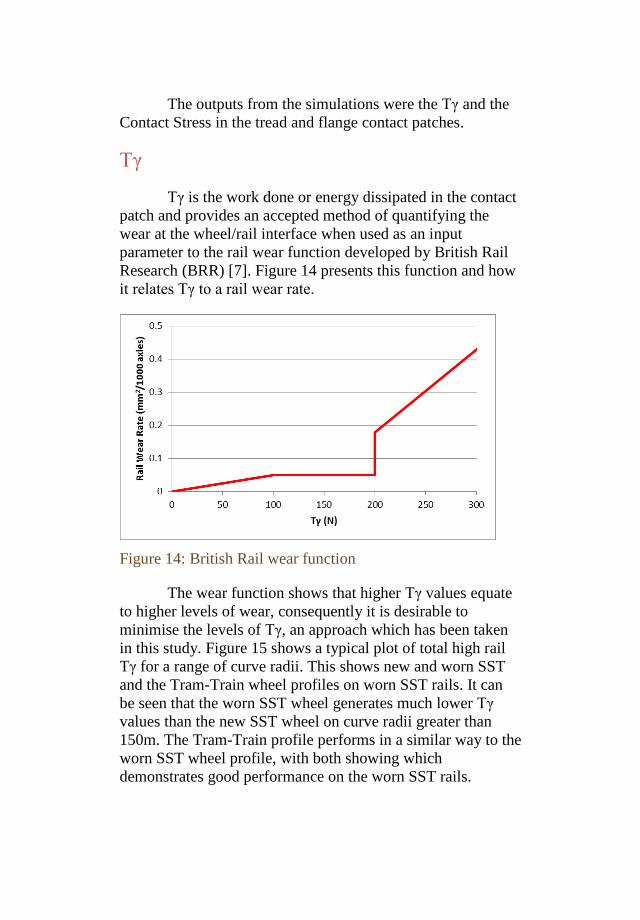
Tγ
Tγ is the work done or energy dissipated in the contact
patch and provides an accepted method of quantifying the
wear at the wheel/rail interface when used as an input
parameter to the rail wear function developed by British Rail
Research (BRR) [7]. Figure 14 presents this function and how
it relates Tγ to a rail wear rate.
Figure 14: British Rail wear function
The wear function shows that higher Tγ values equate
to higher levels of wear, consequently it is desirable to
minimise the levels of Tγ, an approach which has been taken
in this study. Figure 15 shows a typical plot of total high rail
Tγ for a range of curve radii. This shows new and worn SST
and the Tram-Train wheel profiles on worn SST rails. It can
be seen that the worn SST wheel generates much lower Tγ
values than the new SST wheel on curve radii greater than
150m. The Tram-Train profile performs in a similar way to the
worn SST wheel profile, with both showing which
demonstrates good performance on the worn SST rails.
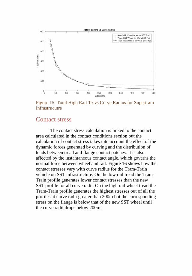
Figure 15: Total High Rail Tγ vs Curve Radius for Supertram
Infrastrucutre
Contact stress
The contact stress calculation is linked to the contact
area calculated in the contact conditions section but the
calculation of contact stress takes into account the effect of the
dynamic forces generated by curving and the distribution of
loads between tread and flange contact patches. It is also
affected by the instantaneous contact angle, which governs the
normal force between wheel and rail. Figure 16 shows how the
contact stresses vary with curve radius for the Tram-Train
vehicle on SST infrastructure. On the low rail tread the Tram-
Train profile generates lower contact stresses than the new
SST profile for all curve radii. On the high rail wheel tread the
Tram-Train profile generates the highest stresses out of all the
profiles at curve radii greater than 300m but the corresponding
stress on the flange is below that of the new SST wheel until
the curve radii drops below 200m.
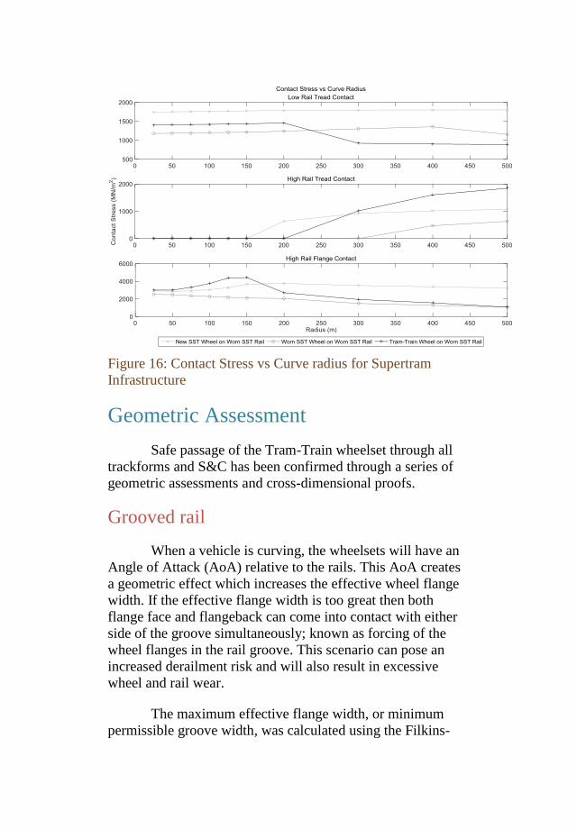
Figure 16: Contact Stress vs Curve radius for Supertram
Infrastructure
Geometric Assessment
Safe passage of the Tram-Train wheelset through all
trackforms and S&C has been confirmed through a series of
geometric assessments and cross-dimensional proofs.
Grooved rail
When a vehicle is curving, the wheelsets will have an
Angle of Attack (AoA) relative to the rails. This AoA creates
a geometric effect which increases the effective wheel flange
width. If the effective flange width is too great then both
flange face and flangeback can come into contact with either
side of the groove simultaneously; known as forcing of the
wheel flanges in the rail groove. This scenario can pose an
increased derailment risk and will also result in excessive
wheel and rail wear.
The maximum effective flange width, or minimum
permissible groove width, was calculated using the Filkins-
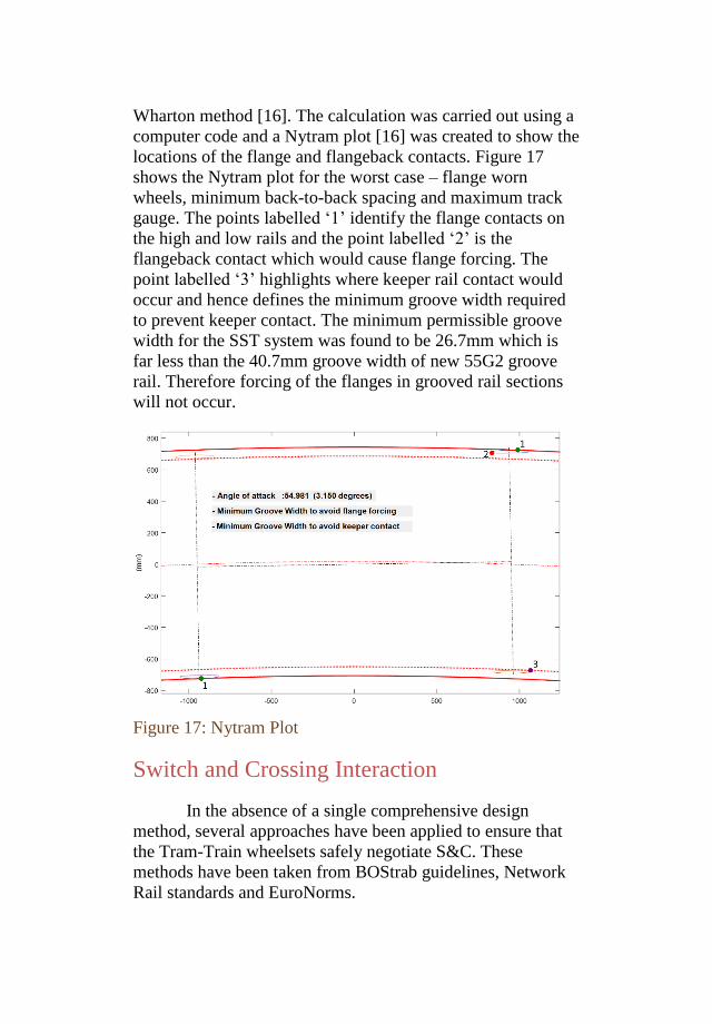
Wharton method [16]. The calculation was carried out using a
computer code and a Nytram plot [16] was created to show the
locations of the flange and flangeback contacts. Figure 17
shows the Nytram plot for the worst case – flange worn
wheels, minimum back-to-back spacing and maximum track
gauge. The points labelled ‘1’ identify the flange contacts on
the high and low rails and the point labelled ‘2’ is the
flangeback contact which would cause flange forcing. The
point labelled ‘3’ highlights where keeper rail contact would
occur and hence defines the minimum groove width required
to prevent keeper contact. The minimum permissible groove
width for the SST system was found to be 26.7mm which is
far less than the 40.7mm groove width of new 55G2 groove
rail. Therefore forcing of the flanges in grooved rail sections
will not occur.
Figure 17: Nytram Plot
Switch and Crossing Interaction
In the absence of a single comprehensive design
method, several approaches have been applied to ensure that
the Tram-Train wheelsets safely negotiate S&C. These
methods have been taken from BOStrab guidelines, Network
Rail standards and EuroNorms.
Blade vertical overlap
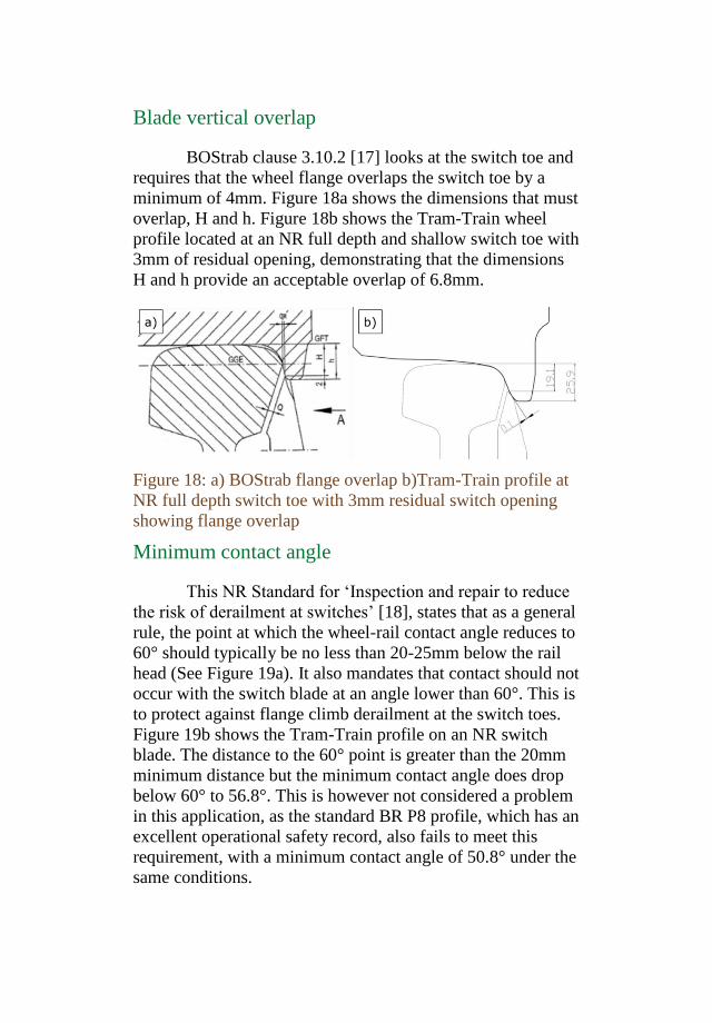
BOStrab clause 3.10.2 [17] looks at the switch toe and
requires that the wheel flange overlaps the switch toe by a
minimum of 4mm. Figure 18a shows the dimensions that must
overlap, H and h. Figure 18b shows the Tram-Train wheel
profile located at an NR full depth and shallow switch toe with
3mm of residual opening, demonstrating that the dimensions
H and h provide an acceptable overlap of 6.8mm.
Figure 18: a) BOStrab flange overlap b)Tram-Train profile at
NR full depth switch toe with 3mm residual switch opening
showing flange overlap
Minimum contact angle
This NR Standard for ‘Inspection and repair to reduce
the risk of derailment at switches’ [18], states that as a general
rule, the point at which the wheel-rail contact angle reduces to
60° should typically be no less than 20-25mm below the rail
head (See Figure 19a). It also mandates that contact should not
occur with the switch blade at an angle lower than 60°. This is
to protect against flange climb derailment at the switch toes.
Figure 19b shows the Tram-Train profile on an NR switch
blade. The distance to the 60° point is greater than the 20mm
minimum distance but the minimum contact angle does drop
below 60° to 56.8°. This is however not considered a problem
in this application, as the standard BR P8 profile, which has an
excellent operational safety record, also fails to meet this
requirement, with a minimum contact angle of 50.8° under the
same conditions.
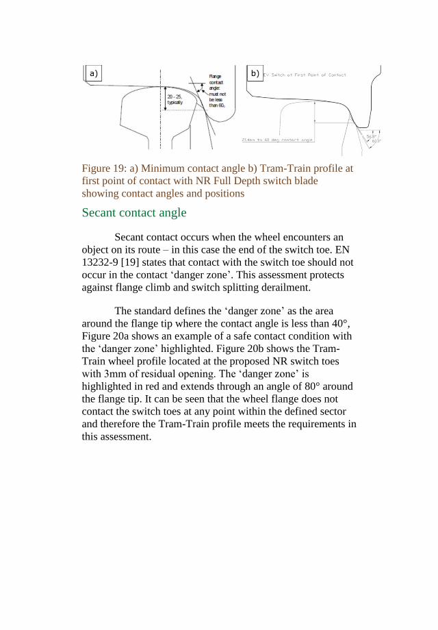
Figure 19: a) Minimum contact angle b) Tram-Train profile at
first point of contact with NR Full Depth switch blade
showing contact angles and positions
Secant contact angle
Secant contact occurs when the wheel encounters an
object on its route – in this case the end of the switch toe. EN
13232-9 [19] states that contact with the switch toe should not
occur in the contact ‘danger zone’. This assessment protects
against flange climb and switch splitting derailment.
The standard defines the ‘danger zone’ as the area
around the flange tip where the contact angle is less than 40°,
Figure 20a shows an example of a safe contact condition with
the ‘danger zone’ highlighted. Figure 20b shows the Tram-
Train wheel profile located at the proposed NR switch toes
with 3mm of residual opening. The ‘danger zone’ is
highlighted in red and extends through an angle of 80° around
the flange tip. It can be seen that the wheel flange does not
contact the switch toes at any point within the defined sector
and therefore the Tram-Train profile meets the requirements in
this assessment.
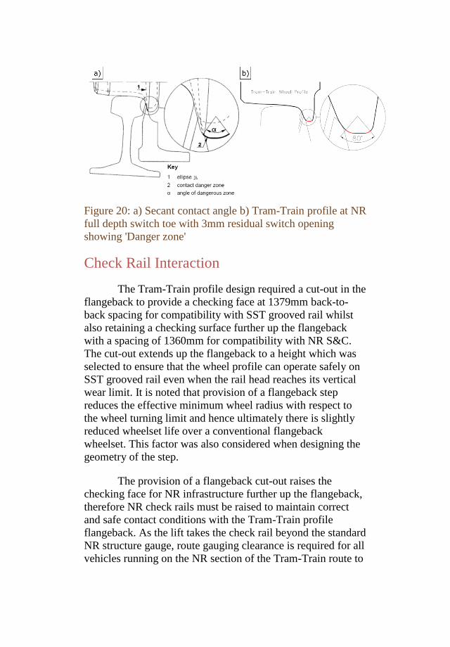
Figure 20: a) Secant contact angle b) Tram-Train profile at NR
full depth switch toe with 3mm residual switch opening
showing 'Danger zone'
Check Rail Interaction
The Tram-Train profile design required a cut-out in the
flangeback to provide a checking face at 1379mm back-to-
back spacing for compatibility with SST grooved rail whilst
also retaining a checking surface further up the flangeback
with a spacing of 1360mm for compatibility with NR S&C.
The cut-out extends up the flangeback to a height which was
selected to ensure that the wheel profile can operate safely on
SST grooved rail even when the rail head reaches its vertical
wear limit. It is noted that provision of a flangeback step
reduces the effective minimum wheel radius with respect to
the wheel turning limit and hence ultimately there is slightly
reduced wheelset life over a conventional flangeback
wheelset. This factor was also considered when designing the
geometry of the step.
The provision of a flangeback cut-out raises the
checking face for NR infrastructure further up the flangeback,
therefore NR check rails must be raised to maintain correct
and safe contact conditions with the Tram-Train profile
flangeback. As the lift takes the check rail beyond the standard
NR structure gauge, route gauging clearance is required for all
vehicles running on the NR section of the Tram-Train route to
ensure that no part of a passing vehicle could contact the
raised check.
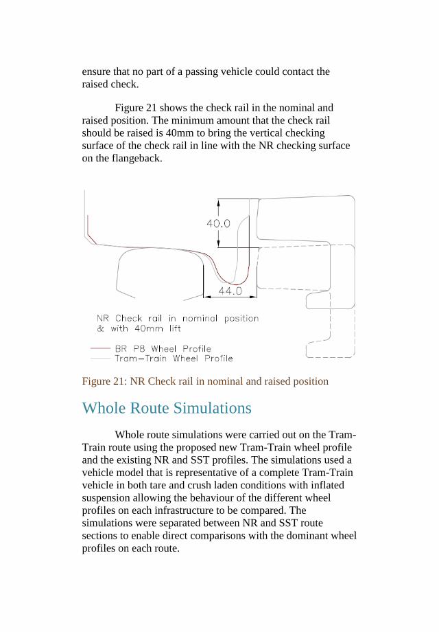
Figure 21 shows the check rail in the nominal and
raised position. The minimum amount that the check rail
should be raised is 40mm to bring the vertical checking
surface of the check rail in line with the NR checking surface
on the flangeback.
Figure 21: NR Check rail in nominal and raised position
Whole Route Simulations
Whole route simulations were carried out on the Tram-
Train route using the proposed new Tram-Train wheel profile
and the existing NR and SST profiles. The simulations used a
vehicle model that is representative of a complete Tram-Train
vehicle in both tare and crush laden conditions with inflated
suspension allowing the behaviour of the different wheel
profiles on each infrastructure to be compared. The
simulations were separated between NR and SST route
sections to enable direct comparisons with the dominant wheel
profiles on each route.
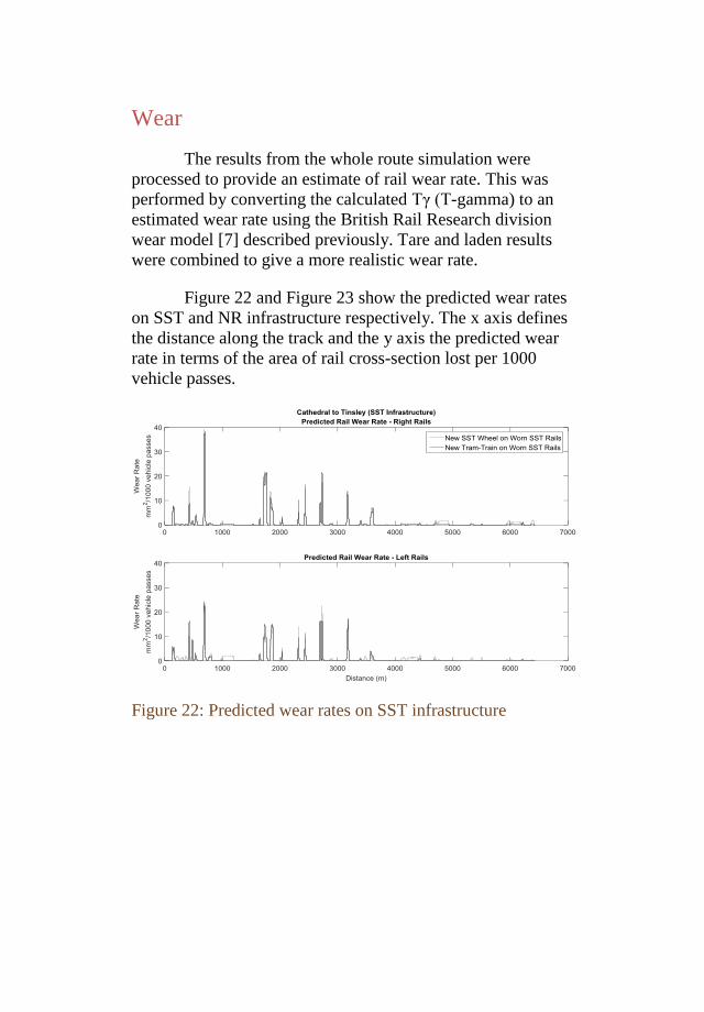
Wear
The results from the whole route simulation were
processed to provide an estimate of rail wear rate. This was
performed by converting the calculated Tγ (T-gamma) to an
estimated wear rate using the British Rail Research division
wear model [7] described previously. Tare and laden results
were combined to give a more realistic wear rate.
Figure 22 and Figure 23 show the predicted wear rates
on SST and NR infrastructure respectively. The x axis defines
the distance along the track and the y axis the predicted wear
rate in terms of the area of rail cross-section lost per 1000
vehicle passes.
Figure 22: Predicted wear rates on SST infrastructure
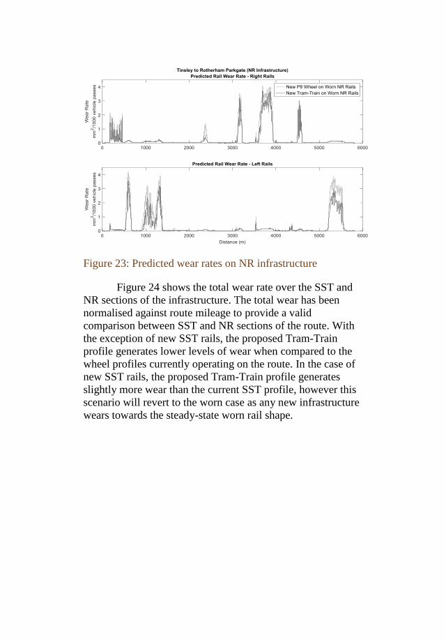
Figure 23: Predicted wear rates on NR infrastructure
Figure 24 shows the total wear rate over the SST and
NR sections of the infrastructure. The total wear has been
normalised against route mileage to provide a valid
comparison between SST and NR sections of the route. With
the exception of new SST rails, the proposed Tram-Train
profile generates lower levels of wear when compared to the
wheel profiles currently operating on the route. In the case of
new SST rails, the proposed Tram-Train profile generates
slightly more wear than the current SST profile, however this
scenario will revert to the worn case as any new infrastructure
wears towards the steady-state worn rail shape.
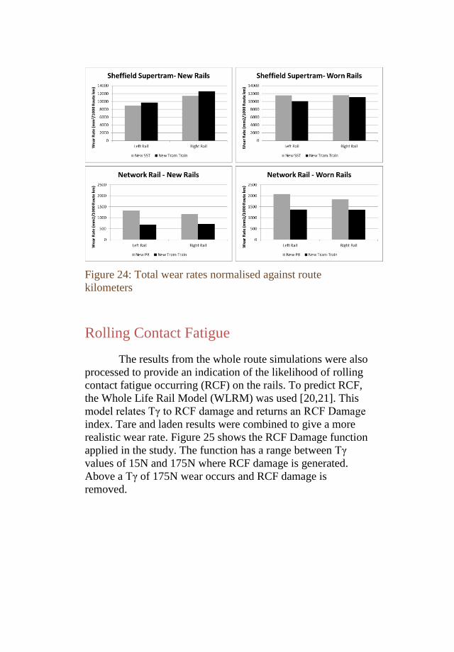
Figure 24: Total wear rates normalised against route
kilometers
Rolling Contact Fatigue
The results from the whole route simulations were also
processed to provide an indication of the likelihood of rolling
contact fatigue occurring (RCF) on the rails. To predict RCF,
the Whole Life Rail Model (WLRM) was used [20,21]. This
model relates Tγ to RCF damage and returns an RCF Damage
index. Tare and laden results were combined to give a more
realistic wear rate. Figure 25 shows the RCF Damage function
applied in the study. The function has a range between Tγ
values of 15N and 175N where RCF damage is generated.
Above a Tγ of 175N wear occurs and RCF damage is
removed.
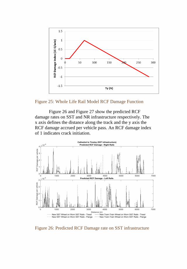
Figure 25: Whole Life Rail Model RCF Damage Function
Figure 26 and Figure 27 show the predicted RCF
damage rates on SST and NR infrastructure respectively. The
x axis defines the distance along the track and the y axis the
RCF damage accrued per vehicle pass. An RCF damage index
of 1 indicates crack initiation.
Figure 26: Predicted RCF Damage rate on SST infrastructure
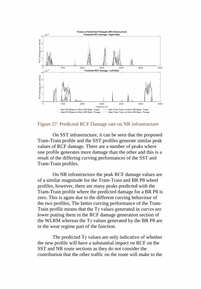
Figure 27: Predicted RCF Damage rate on NR infrastructure
On SST infrastructure, it can be seen that the proposed
Tram-Train profile and the SST profiles generate similar peak
values of RCF damage. There are a number of peaks where
one profile generates more damage than the other and this is a
result of the differing curving performances of the SST and
Tram-Train profiles.
On NR infrastructure the peak RCF damage values are
of a similar magnitude for the Tram-Train and BR P8 wheel
profiles, however, there are many peaks predicted with the
Tram-Train profile where the predicted damage for a BR P8 is
zero. This is again due to the different curving behaviour of
the two profiles; The better curving performance of the Tram-
Train profile means that the Tγ values generated in curves are
lower putting them in the RCF damage generation section of
the WLRM whereas the Tγ values generated by the BR P8 are
in the wear regime part of the function.
The predicted Tγ values are only indicative of whether
the new profile will have a substantial impact on RCF on the
SST and NR route sections as they do not consider the
contribution that the other traffic on the route will make to the
route RCF damage levels. To fully assess the change in RCF
damage, post Tram-Train introduction, it would be necessary
to model all vehicle types on the route and sum the RCF
damage generated by each vehicle pass. However, as the
Tram-Train vehicle will form only a small proportion of the
total traffic on each system, it is not considered there will be
significant impact on the RCF damage on either SST or NR
systems.
Conclusions
A dual operation wheel profile has been designed to
run on Network Rail and Sheffield Supertram infrastructure.
The design incorporates several features to meet the
requirements of the two rail systems such as:
Cut-out in the flange back to provide two checking
surfaces for compatibility with NR check rails and SST
grooved rails
68° flange angle with bespoke flange toe profile to
provide required clearance for safe passage through
NR switch toes
Flat flange tip to facilitate flange tip running through
SST diamond crossings
Tread geometry derived from the BR P8 profile that
avoids hard two-point contact, reduces wear and
improves curving performance
The work has shown that it is possible to design an
effective dual operation wheel profile even when the rail
profile shapes encountered on the light and heavy rail sections
of the route are very different. Through an iterative process of
stepwise refinement and assessment, the wheel profile tread
geometry has been developed to provide a level of
performance in terms of contact conditions, rail wear and
vehicle behaviour that was similar or better than the current
SST and NR profiles. This ensures that the new Tram-Train
profile will not have any significant impact on the asset life of
the two infrastructures. The new Tram-Train profile provides
the following characteristics:
Rolling Radius Difference and conicity levels that do
not exceed current wheel/rail combinations in order to
prevent vehicle stability problems
Contact stresses that do not exceed current levels
Sufficient resistance to derailment
Tγ levels that do not exceed current levels
Reduced wear rates when compared to current profiles
Indicative RCF levels that are not excessive when
compared to existing profiles
A full geometric assessment has been undertaken to
ensure the new profile can safely negotiate all of the track
features found on NR and SST infrastructure including:
Grooved rail
Check rails and Guard Rails
Switches with residual switch opening
Common crossings
Diamond crossings (including flange tip running
crossings)
During the development of the profile it was identified
that the check rails on NR infrastructure would need to be
raised to allow the new wheel profile design to work. As part
of the geometric analysis, a minimum check rail height of
40mm above the running rail was defined.
The final wheel profile design is illustrated in Figure
28.
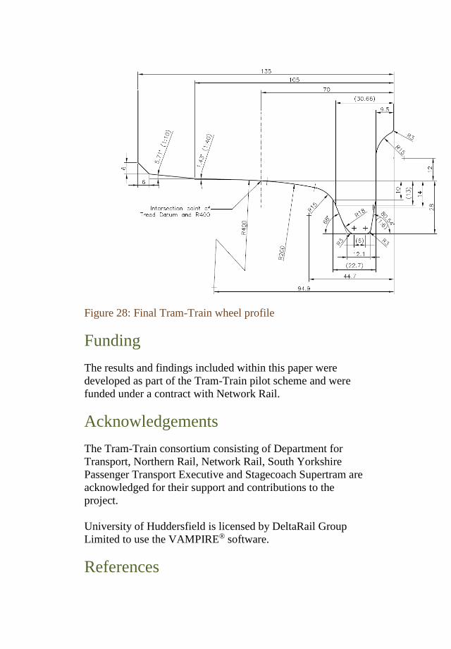
Figure 28: Final Tram-Train wheel profile
Funding
The results and findings included within this paper were
developed as part of the Tram-Train pilot scheme and were
funded under a contract with Network Rail.
Acknowledgements
The Tram-Train consortium consisting of Department for
Transport, Northern Rail, Network Rail, South Yorkshire
Passenger Transport Executive and Stagecoach Supertram are
acknowledged for their support and contributions to the
project.
University of Huddersfield is licensed by DeltaRail Group
Limited to use the VAMPIRE® software.
References
1. Duewag Drawing No. 3-D-02-Y-09006320, Sheffield
Supertram Wheel Tyre.
2. “Railway applications – Track - Special purpose rail -
Grooved and associated construction”, BS EN
14811:2006+A1:2009.
3. “Railway applications – Track - Rail - Part 4: Vignole
railway rails from 27kg/m to, but excluding 46 kg/m”,
EN 13674-4:2006+A1:2009.
4. Rail Safety and Standards Board (2012), “Railway
Wheelsets”, GM/RT2466.
5. “Railway applications - Track - Rail - Part 1: Vignole
railway rails 46 kg/m and above”, BS EN 13674-
1:2003+A1:2007.
6. Allen, P. (2008), “Support for the Introduction of
Tram-Train Vehicles on Network Rail Infrastructure”,
RTU Report 81/13 Issue 2.
7. McEwan I. J. and Harvey R. F. (1986), “Technical
Memorandum – Interpretation of Wheel Wear
Numbers”, British Rail Research Report TM-VDY-
004.
8. DeltaRail Group Ltd (2016), “VAMPIRE Help
Manual”, Version v6.40.
9. UIC (2005), “A Survey of Current Wheel and Rail
Interface Design and Management Practices”. UIC
Documentation Centre Database (Raildoc).
10. Iwnicki, S. I. (2006), “Handbook of Railway Vehicle
Dynamics”. CRC Press.
11. Allen P.D. and Bevan A. (2008), “Determination of
Tramyway Wheel and Rail Profiles to Minimise
Derailment”. RTU Report 90/3/A.
12. Ringsberg, J.W. (2000), “Cyclic Ratchetting and
Failure of a Pearlitic Rail Steel”. Fatigue & Fracture of
Engineering Materials & Structures. 23(9): p. 747-758.
13. Beynon, J.H., J.E. Garnham, and K.J. Sawley (1996),
“Rolling Contact Fatigue of Three Pearlitic Rail
Steels”, Wear. 192(1-2): p. 94-111.
14. Sinclair, J.C. and Allery M.B.P. (1991), “Development
of a Failure Parameter for Rail Squats”. British Rail
Research Report TM MF 211.
15. Pearce, T.G. (1993), “Derivation of Conicity and
Contact Angle Parameter from Rolling Radius
Difference and Contact Angle Difference Graphs”.
British Rail Research.
16. Transportation Research Board (2012), “Track Design
Handbook for Light Rail Transit, Second Edition”,
ISBN 978-0-309-25824-1.
17. “Regulations on the Guidance of Rail Vehicles in
accordance with the German Federal Regulations on
the Construction and Operation of Light Rail Transit
Systems (BOStrab) - Guidance Regulations (SpR)”,
March 2004, English translation by J Snowden Sept.
2008.
18. Network Rail (2008), “Inspection and repair to reduce
the risk of derailment at switches”, NR/L2/TRK/0053
Issue 5
19. “Railway applications - Track - Switches and crossings
- Part 9: Layouts”, BS EN 13232-9:2006+A1:2011
20. Burstow, M., “Whole Life Rail Model Application and
Development for RSSB – Development of an RCF
Damage Parameter”, AEA Technology Rail report
AEATR-ES-2003-832 Issue 1, 2003.
21. Burstow, M., “Whole Life Rail Model Application
and Development for RSSB – Continued Development
of an RCF Damage Parameter”, AEA Technology Rail
report AEATR-ES-2004-880 Issue 2, 2004.