Embed Size (px)
Citation preview
NOCLAS
NOCLAS DOCUMENT DATE: 10/25/2012
Design and Integration of a
Mechanical Aircraft Control System
Mixer for Ruddervator Surfaces
Advanced Tech Engineering, Inc.

NOCLAS
NOCLAS DOCUMENT DATE: 10/25/2012
Design a control mechanism mixer that
mechanically controls ailerons, and
(v-tailed) ruddervators using a
single handed yoke. Its movement
should mimic the Microsoft Sidewinder
Joystick. The mixer can be designed
to connect to cables or pushrods, but
I am not interested in the runs to
the control surfaces, just the mixer.
Size and cost are important design
factors.
I'd like for you to clearly depict
the design solution using hand
sketches and hand drawings. I would
also like you to supply me with how
many hours it took to complete the
concept.
MS
Sidewinder
Joystick
5.4”
Requirements

NOCLAS
NOCLAS DOCUMENT DATE: 10/25/2012
Aircraft:
- Center-Stick Tandem Seating Aircraft
Simplicity:
- No use of gears and complex linkages
- Keep the system low cost and low mass (i.e. size for stiffness, then
strength)
System:
- All Control Surfaces have Control Horns with Moment Arms ~ 0.6"
- Direct Mechanical Linkage and Mechanical Gain (increase or decrease through
lever design) only through bell cranks and levers
Calculations:
- Use Small angle Approximations (for angles < 3 deg) in force-moment
calculations
- Maximum Control Surface Deflection are to be +30 deg for all Control
Surfaces
- Control Surface Deflection Rates to be at least 60 deg/sec
- Control Surface Unit Weight = 3 lb/ft2 (may be high, but will use this for
now)
- Wingspan = 36 ft
- Wing Chord = 6 ft
- Aileron Length = 50% of b/2 = 9 ft (Outboard Half of Semi-span)
- Aileron Chord = 20% of Wing Chord = 21.6 in
Assumptions

NOCLAS
NOCLAS DOCUMENT DATE: 10/25/2012
- Stall Speed = 50 KTAS at SLS where Q = 8.5 psf
- Tail has Similar Aspect Ratio, but 1/3 Projected Horizontal Area with
a 45 deg Dihedral
Loads:
- Zero Total Forces and Moments on Stick and Rudder Pedals in Neutral
Position through the Flight Envelope
- Balance the use of Tension Only Members (i.e. cables) vs. Push Rods
to optimize tradeoff between Slop/Tolerance and Overall System Mass
- Check Flight Envelope Highest Dynamic Pressure of 135 psf (200 KTAS
at SL) vs. 6 g's Load Factor at Stall Speed Q and use the maximum
Control Surface Moments of the two.
- Maximum Stick Input Forces (5th Percentile Male at 1G Load Factor
from Human Engineering Bulletin 56-5H) below the 100 KTAS Assumed
Maneuver Speed
- Aft Force = 42 lb (Pos X direction)
- Fwd Force = 30 lb (Neg X direction)
- Right Side Force = 15 lb (Pos Y direction)
- Left Side Force = 8 lb (Neg Y direction)
- Left Rudder Pedal Push Force = 334 lb (Neg X direction)
- Right Rudder Pedal Push Force = 246 lb (Neg X direction)
Assumptions (cont.)
NOCLAS
NOCLAS DOCUMENT DATE: 10/25/2012
The method used in sizing Mixing Moment
Arm Structure is explained below:
The Maximum Travel of the Stick at + 30
degrees is fixed as equivalent to the
corresponding Control Surface Maximum
Deflections of + 30 degrees (see
Assumptions). Also, the maximum
Ruddervator Deflection Angle and the
Maximum Rudder Pedal Deflection of + 20
degrees (see Assumptions and
Illustration on left) correspond.
The Rudder Pedal input is transferred
aft to the Mixer to a point that is at
the same waterline as the pivot axis.
Thus, the Stick Pitch Deflection
remains unaffected.
Likewise, any Stick Pitch input that is
transferred aft to the mixer does not
transfer any rotation forward to the
Rudder Pedals, leaving the two
ruddervator affecters independent of
each other.
Answer – Methods

NOCLAS
NOCLAS DOCUMENT DATE: 10/25/2012
The Mixer Assembly sits aft of the co-pilot in a tandem configuration aircraft. Push
Rods run forward from the Ruddervators and aft from the Stick (Roll Input). Tension
cables run from just outboard of the Rudder Pedals aft to where they address the Mixer
as shown in the given illustration. The Roll Control function is not part of this
mixing system and is intended to be the standard push rod and bell horn layout running
outboard to the wing.
Due to no requirement to understand loads, the maximum Control Surface Moments are not
described in this project. However, this could be done using first-order analysis such
as a flat plate with drag calculated as the Dynamic Pressure applied to the Exposed
Control Surface centroid. Another calculation could be the maximum Load Factor
condition pulling on the full control surface mass at the surface centroid coupled with
the minimum drag vector (as stated earlier), to maximize the total Control Surface
Moment. Depending on what the Maximum Load Factor is, the Maximum Moment can be
understood.
These maximum loads would be used to size the structural members that compose the Mixer
Assembly, the Tension Cables running forward to the Rudder Pedals and it’s respective
fasteners, the Push Rods running from the Control Stick, and it’s fasteners, to the
Mixer and directly to the Ailerons through bell horns. (I can go into more depth on
these calculations if you’d like later).
The development of Stick Force Feel can accomplished by understanding the desired stick
forces (% of Max Load on a 5th Percentile Human) for given Flight Envelope conditions and
using levers such as bell cranks to dial the stick force up and down accordingly.
A pitch trim mechanism can be created by applying a variable spring force (non-aero
trim) on the Control Stick in the Pitch Axis.
Answer - Design Details

NOCLAS
NOCLAS DOCUMENT DATE: 10/25/2012
As drawn
Dimensions are:
A = 2.0 inches
B = 6.0 inches
C = 2.0 inches
D = 3.8 inches
Answer – Isometric View

NOCLAS
NOCLAS DOCUMENT DATE: 10/25/2012
QTY DASH NO. CAGE CODE PART NO. NOMENCLATURE MATERIAL NOTES
1 -103 PLATE, MOUNTING CRES 1.0" COUNTERBORE, 1/2" DIA 4 HOLE PATTERN
1 -101 MIXER STRUCTURE ALUMINUM 1" DIA ALUMUNUM TUBE X 6' LENGTH
2 070U6 AN42B-27 BOLT, EYE CRES 3/16" DIA, UNF, 2.5" GRIP LENGTH
4 AS 18-2-G SLEEVE, COMPRESSION
2 070U6 CABLE 3/32" DIA, 120.0" LENGTH
3 070U6 AN665-34R CLEVIS, MALE THREAD CRES 1/4" DIA HOLE
2 070U6 AN100-X THIMBLE, CABLE
3 070U6 INSERT CRES 3/8" ID, 1/2" OD, 1.0" LENGTH
1 070U6 JOINT, BALL 1.0" SPHERICAL HEAD
4 070U6 NUT, JAM CRES 3/16" DIA, UNF, 1/4" THICK
9 070U6 NUT, JAM CRES 3/8" DIA, UNF, 1/4" THICK
8 070U6 NUT, LOCKING CRES 1/8" DIA
6 AN381-153 PIN, COTTER CRES 18-8
0 AN395-47 PIN, CLEVIS CAD PLATED 1/4" DIA, 1.5" LENGTH
3 070U6 ROD END CRES 3/8" DIA
3 070U6 ROD, PUSH CRES 3/8" DIA
8 070U6 SCREW CRES 1/8" DIA
4 070U6 AN960 WASHER, FLAT CRES 3/16" DIA, 0.031" THICK
9 070U6 AN960 WASHER, FLAT CRES 3/8" DIA, 0.031" THICK
4 070U6 WASHER, LOCKING CRES 3/16" DIA, 0.031" THICK
9 070U6 WASHER, LOCKING CRES 3/8" DIA, 0.031" THICK
MIXER
Below is a notional (incomplete) parts list for this system.
Answer - Parts List

NOCLAS
NOCLAS DOCUMENT DATE: 10/25/2012
Answer - Sketches
View Looking Down
The two given illustrations
characterize the Degrees of
Freedom that are allowed by the
Ball Joint at the bottom of the
Mixer Assembly.
View Looking Inboard
Displacement of the Push Rods and
Tension Cables can be calculated by
the maximum deflection of either the
Rotated Control Surfaces or the
Rotated Control Stick, to whichever it
is connected.
Per the above illustration, Distances
E, F & G have been found in the
analysis given in the next slide.
As drawn
Dimensions are:
A = 3.8 inches
B = 6.0 inches
C = 2.0 inches
D = 2.0 inches
Half Travel:
E = 0.38 inches
F = 0.30 inches
G = 0.30 inches * Note: These dimensions do not
correspond to those noted on the
previous slide.

NOCLAS
NOCLAS DOCUMENT DATE: 10/25/2012
Answer - Calculations
NOCLAS
NOCLAS DOCUMENT DATE: 10/25/2012
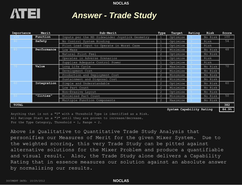
Answer - Trade Study Trade Study
Importance Merit Sub-Merit Type Target Rating Risk Score
100 Function Inputs per the MS Sidewinder Joystick Geometry 1 Optimize 5 No Risk 100
No Control System Binding 1 Optimize 3 Risk
Pilot Load Input to Operate in Worst Case 1 Optimize 3 Risk
Low Mass 2 Minimize 3 No Risk
Natural Pilot Feel 2 Optimize 3 No Risk
Operates in Adverse Scenarios 1 Optimize 3 Risk
Supplies Adequate Control Power 1 Optimize 3 Risk
Long Life Cycle 2 Maximize 5 No Risk
Development Cost 2 Minimize 5 No Risk
Production and Deployment Cost 2 Minimize 5 No Risk
Sustainment and Disposal Cost 2 Minimize 5 No Risk
Simple and Understandable 2 Optimize 5 No Risk
Low Part Count 2 Minimize 5 No Risk
Non-Evasive Layout 2 Optimize 5 No Risk
Minimized Part Count 2 Minimize 5 No Risk
Multiple Function Components 2 Maximize 5 No Risk
382
System Capability Rating 84.9%
Anything that is not a "5" with a Threshold Type is identified as a Risk.
All Ratings Start as a "3" until they are proven to increase/decrease.
For the Type Category, Threshold = 1, Range = 2.
Safety
TOTAL
"Ilities"
Integration
Value
Performance
60
50 50
60
48
54
70
90
80
70
Above is Qualitative to Quantitative Trade Study Analysis that
personifies our Measures of Merit for the given Mixer System. Due to
the weighted scoring, this very Trade Study can be pitted against
alternative solutions for the Mixer Problem and produce a quantifiable
and visual result. Also, the Trade Study alone delivers a Capability
Rating that in essence measures our solution against an absolute answer
by normalizing our results.

NOCLAS
NOCLAS DOCUMENT DATE: 10/25/2012
Answer - Risk Mitigation
5 5 6 7 8 9
4 4 5 6 7 8
3 3 4 5 6 7
2 2 3 4 5 6
1 1 2 3 4 5
1 2 3 4 5
Low Risk = 1 - 3
Medium Risk = 4 - 6
High Risk = 7 - 10
Risk
Control System Binding
Adequate Pilot Load Input to Operate in Worst Case
Supplies Adequate Control Power
Level - Likelyhood of Occurrence
Level - Consequences
From the Trade Study
Analysis in the previous
slide, we can conclude
that there are several
Risks that will absolutely
need to be addressed prior
to engaging in production
of any Airborne
Prototypes.
These Risks are
demonstrated in this chart
at their perceived Levels.
We have a propensity to
eliminate any and all risk
in buildable hardware.
However, as illustrated by
the blue arrow, we can
only translate our Total
Risk Level left due to our
inability to change our
assumed Consequences, for
this case.

NOCLAS
NOCLAS DOCUMENT DATE: 10/25/2012
- Design will be sensitive to Operating
Load Factor (g's)
- We want to design into the system a
direct relation between Stick Forces and
Dynamic Pressure (KEAS) for Safety (i.e.
don't rip wings off at high Q, smoother
flight, non-aerobatic maneuvers)
- Maximize chord lengths on control
surfaces to decrease sensitivity at
higher dynamic pressure (for Safety).
- Be aware of Stick Movement Envelope
(+30 deg roll (stick), +30 pitch
(stick), +20 deg yaw (pedals)) and it's
relation to forces from Dynamic Pressure
and Load Factor
- Be careful to prevent binding of
Control System in any way (i.e. sliding
elements, if any, from "racking", stick
and rudder pedal forces to not counter
each other within the linkages and
maintain straight hingelines (minimize
curvature of bent hingeline) at high
Load Factors.
Sensitivities

NOCLAS
NOCLAS DOCUMENT DATE: 10/25/2012
Alternatives
- I have an alternate, less robust concept of sliding sleeves
and stops conceptually designed.
- May consider use of only push rods to minimize slop if
necessary.
- May develop more ideas for changes in this layout to
accommodate:
- Side-by-side seating with a centerstick
- Side-by-side seating with a sidestick
- Tandem seating with a sidestick


![REAL TIME ANALYSIS FOR AIRCRAFT USING EMC LABS€¦ · Mechanical failures (loss of aircraft) originating from turbine engine failures are the main cause of aircraft disasters[1]](https://img.pdfslide.us/doc/110x75/5f0cd0607e708231d43742cc/real-time-analysis-for-aircraft-using-emc-labs-mechanical-failures-loss-of-aircraft.jpg)