Embed Size (px)
Citation preview

ADVANCED AIRCRAFT ELECTRICAL SYSTEM CONTROL TECHNOLOGY DEMONSTR--ETCftJ)
NLASF JAN 82 T R BOLIT. G L DUNN, D E HANKINS F33615-80-C-20ON
UNLSIIED DISA25273 AFAL-TR-1-2128 NL

AFWAL TR -81 -2128
SADVANCE AFCRAFT ELECTRIAL SSE* ~ CONTROL TECHNOOGY DEMONSTO
t~i r- Phase 1: Analysis & Preliminary DesignOtt
G. LDunnD. E. HankinsP. J. Leong1. S. Mebdi
BOEING MILITARY AIRPLANE COMPANYSEATTLE , WASHINGTON
JANUARY 1982
* INTERIM REPORT FOR THE PERIOD MARCH 1981 TO OCTOBER 1981
1APPROVED FOR PUBLIC RELEASE; DISTRIBUTION UNLIMITED]
AERO PROPULViON LABORATORY
SAIR FORCE WRIGHT AERONAUTICAL LABORATORIESAIR FORCE SYSTEMS COMMAND V
* WRIGHT- PATTERSON AIR FORCE BASE, OHIO 45433
82 04 19 089

When Government drawings, specifications, or other data are used for any purpose
other than in connection with a definitely related Government procurement operation,
the United States Government thereby incurs no responsibility nor any obligationwhatsoever; and the fact that the government may have formulated, furnished, or inany way supplied the said drawings, specifications, or other data, is not to be re-garded by implication or otherwise as in any manner licensing the holder or anyother person or corporation, or conveying any rights or permission to manufactureuse, or sell any patented invention that may in any way be related thereto.
This report has been reviewed by the Office of Public Affairs (ASD/PA) and isreleasable to the National Technical Information Service (NTIS). At NTIS, it willbe available to the general public, including foreign nations.
This technical report has been reviewed and is approved for publication.
DUANE G. FOX PAUL R. BERTHEAUDProject Engineer Technical Area ManagerPower Systems Branch Power S.stems BranchAerospace Power Division Aerospace Power Division
FOR THE COMMANDER
C?ief, Aerospace Power DivisionAero Propulsion Laboratory
"If your address has changed, if you wish to be removed from our mailing list, orif the addressee is no longer employed by your organization please notifyy ,FJL/QQO 2.W-PAFB, OH 45433 to help us maintain a current mailing list".
Copies of this report should not be returned unless return is required by securityconsiderations, contractual obligations, or notice on a specific document.

UNCLASSIFIEDSECURITY CLASSIFICATION OF THIS PAGE (Wlhen Dote Entered)__, , RAD INSTRUCTIONS
REPORT DOCUMENTATION PAGE BEORE COPLEN FORM
1. REPORT NUMBER 2. GOVT ACCESSION NO. S. RECIPIENT'S CATALOG NUMBER
AFWAL-TR-81-2128 1 YA t2 .4. TITLE (and Subtitle) S. TYPE OF REPORT A PERIOD COVERED
Advanced Aircraft Electrical System Control Interim Technical ReportTechnology Demonstrator Phase I - Analysis Mar 1, 1981 - Sept 30, 1981
6. PERFORMING O'%G. REPORT NUMBER
And Preliminary Design D180-25927-37. AUTHOR(e) S. CONTRACT OR GRANT NUMBER(s)
T. R. Boldt P. J. Leong F33615-80-C-2004G. L. Dunn I. S. Mehdi0. E. Hankins
9. PERFORMING ORGANIZATION NAME AND ADDRESS III. PROGRAM ELEMENT. PROJECT. TASKLOW AREA A WORK UNIT NUMBERSMechanical/Electrical Systems TechnologyBoeing Military Airplane CompanyM/S 47-03, P.O. Box 3707, Seattle, WA 98124
I. CONTROLLING OFFICE NAME AND ADDRESS 12. REPORT DATE
Aero Propulsion Laboratory (P00) January 1982Air Force Wright Aeronautical Laboratories, AFSC 13. NUMBEROFPAGES
Wright-Patterson Air Force Base. Ohio 45433 13314. MONITORING AGENCY NAME B ADDRESS(I difertl from Controlling Office) IS. SECURITY CLASS. (of this report)
Uncl assi fledIS&. DECL ASSIFICATION/ DOWNGRADING
SCHEDULE
16. DISTRIBUTION STATEMENT (ol this Report)
Approved for public release; distribution unlimited.
17. OISTRIBUTION STATEMENT (of the abstract entered in Block 20. it dllrent from Report)
IS. SUPPLEMENTARY NOTES
IS. KEY WORDS (Continue on reverse side it neceary and Identify by block number)
DAIS Load ManagementElectrical Load Management Center (ELMC) Remote Terminal (RT)Electrical System Solid State Power Controller (SSPC)EMUX
54. AISTRACT (Continue on reverse side It nocoeboary a" Identify by block number)
This report summarizes Task I and-[and documents the results of Task 3,Phase I, of this two-phase program. Task 3 is the preliminary design of anadvanced aircraft electrical system (AAES). The AAES is designed to meet therequirements of a 1990 time frame two-engine tactical aircraft with multi-mission capability. The MES performs the functions of power generation,distribution and control of power to loads, system protection, and loadmanagement. Key characteristics of the AAES are:
DD I ja 1473 toToN oF NOVI1 sIoBOLERE UNCLASSIFIEDSECURITY CLASSIFICAION OF THIS PAGE (Pha.n Date Mfttered)

UNCLASSIFIEDSECURITY CLASSIFICATION OF THIS PAGE(Wham Date BAnerd)
20. ABSTRACT (rontin.q)
o -ntegrated avionics and power data bus configuration consisting ofDigital Avionics Information System (DAIS) standard elements (MIL-STD-1750 processor, MIL-STD-1553B data bus, controls and displays, andremote terminals (RT)).
o --.Intelligent Electrical Load Management Centers (ELMC) capable ofcontrolling power to loads
o --Built-in-test (BIT) capability to isolate faults to the module level.BIT includes both circuit and data monitoring checks)
o Solid State Power Controllers (SSPC) to replace circuit breakers andpower control switches. SSPCs are turned on/off via computer control,
o Generator control, protection and status monitoring by a GeneratorControl Unit (GCU) compatible with DAIS hardware and software.
. Multimission data information system through programmable system* - processors, ELMCs and standard DAIS elements,
o Automatic load management for increased aircraft survivability andprobability of mission completion.
UNCLASSIFIEDSECuRiTY CLASSIFICATION OF ?' PAGEWbhun Data Ente~rd)

,
PREFACE
This Interim Technical Report presents the results of work performed by the
Boeing Pilitary Airplane Company, Seattle, Washington, under Air Force
Contract F33615-80-C-2004, during the period from arch through September
1981. The work is sponsored by the Aero Propulsion Laboratory, Air Force
Wright Aeronautical Laboratories, Wright-Patterson Air Force Base, Ohio, under
Project 3145, Task 314529, Work Unit 31452959 with ir. Duane G. Fox,
AFWAL/POOS-2, as project engineer.
This document, which covers Task 3, Preliminary Design, of Phase I, fulfills
the requirements of CEPL item number 9.
The program manager is I. S. Mehdi. The report was prepared 1y T. R. Boldt,
G. L. Dunn, D. E. Hankins, and P. J. Leong who were technically responsible
for the work.
AceessiOn ?or
uiis CRUZ&D.tC TA3UrkoinfS1IC4 0
arm Justificatt
con1 oINSPECtED
2 Di~trlbuti1fi/__AvailablItY CoesAva li and/or
- --tr - Special

TABLE OF CONTENTS
SECTION PAGE
I. INTRODUCTION 11. Background 12. Program Objectives 23. Approach 2
HI. REQUIREMENTS ANALYSIS AND CONCEPTUAL DESIGN 61. Requirements Analysis 6
a. Load Analysis 7b. Generation System 9
c. Distribution System 10d. Flight Critical Power 11e. Power Bus Configuration 13f. System Control and Protection 13g. Applicability of J73/I (Jovial) 17h. Controls and Displays 17
2. Control System Requirements 20a. Processing Requirements 22b. Input/Output Requirements 23c. Response Time 23d. Avionics Bus Loading 24
3. Technical Analysis 25a. General Assumptions 27b. Processor Loading 29
c. Data Bus Loading 30d. Vemory Requirements 30e. Reliability 31f. Results of the Technical Analysis 32
4. Economic Analysis 335. Conceptual Design 34
a. Data Bus Architectures 34b. Non-Integrated Data Bus Architecture 35
V

TABLE OF CONTENTS (continued)
SECTION PAGE
c. Integrated Data Bus Architecture 37d. Hierarchical Data Bus Architecture 39
6. Selected Concept for Preliminary Design 41
III. ADVANCED AIRCRAFT ELECTRICAL SYSTEM PRELIMINARY DESIGN 421. Power System Configuration 42
a. System Characteristics 44(1) AC System 45(2) DC System 45(3) External Power 47(4) A~uxiliary Power 48
(5) Generator Control Unit 48b. System Operation 50
(1) Startup 51
(2) Steady State Operation 54(3) Generator Failure and Faults 54(4) External Power Operation 57(5) Auxiliary Power Operation 57(6) Processor and Data Bus Failure 57(7) Load Panagement 57
2. Integrated Power System Control 58a. Multiplex Date Bus Characteristics 58b. Avionics/Electrical Control System Interface 60c. Electrical Control System 60
(1) Power System Processor 64(a) PSP Hardware Description 64(b) PSP Functional Requirements 64Wc PSP Executive Software 67(d) PSP Applications Software 75
(2) Electrical Load Panagment Center 82(a) ELKC Functional Description 84
()SSPC Control anid Monitoring 84
vi

TABLE OF CONTENTS (continued)
SECTION PAGE
(c) Aircraft Discretes and Analog Signal
Monitoring 86
(d) ERT Software Computations 86
(e) Built in Test 86
(3) Power Controllers 86
(a) Solid State Power Controllers 86
(b) Electro-Mechanical Power Controllers 87
(4) Electrical Remote Terminal 89
(a) ERT Functional Description 89
.l (b) ERT Executive Software 94
(c) ERT Applications Software 96
(5) Remote Terminal 99
(6) GCU/Data Bus Interface 103
(7) AGCU/Data Bus Interface 103
(8) EPCU/Data Bus Interface 106
3. Reliabililty, Maintainability, and Safety 106
IV. LABORATORY SIMULATOR PRELIMINARY DESIGN 108
1. Configuration 108
2. Hardware 108
a. Bus Monitor 110
b. System Test Console 110
c. Generator Stand 110
d. Load Bank 110
e. Generator Control Unit 110
f. Electrical Load Management Center 111g. AN/AYK-15A Computer 111
h. Console with CRT 111
i. Avionics Simulator and Bus Controller 111
j. Remote Teminal 112
3. Software 112
Vtii

TABLE OF CONTENTS (continued)
SECTION PAGE
V. WORK EFFORTS FOR DETAILED DESIGN 113
1. Avionics Processor 113
2. Power System Processor 113
3. ELK( 114
a. ELMC Hardware 114
(1) SSPCs 114
(2) ERT 115
b. ERT Software 115
(1) ERT Executive Software 115
(2) ERT Application Software 115
4. Remote Terminals 115
5. GCU 116
6. Controls and Displays 116
VI. CONCLUSIONS AND RECOMWENDATIONS 117
1. Results and Conclusions 117
. 2. Recommendations 118
REFERENCES 120
vtti

LIST OF FIGURES
FIGURE PAGE
1 Phase 1 Program Flow Chart 42 Electrical Load Profile 8
3 Flight Critical Bus in the ELI4C 12
4 Power Bus Configuration 14
5 Load Management Matrix 186 Load Vanagement Level Selection 19
7 DAIS Integrated Controls/Displays 21
*18 Data Bus Architecture Configurations 26
9 Baseline Non-Integrated Architecture 36
10 Integrated Architecture 38
11 Hierarchical Architecture 4C
12 Aircraft Electrical System Configuration 43
13 AC and DC Power System Configuration 46
14 Generator Control Unit Functional Diagram 4915 Electrical System Startup 5216 Power System Operational Diagram 5317 Processor Control Panel 5518 Integrated Avionics and Electrical Control System
Functional Diagram 'N 5919 1553B Bus Vessage Word Formats 6120 Bus Message Formats 6221 Power System Processor Control and Status Data Flow 6622 Power System Processor Architecture with PSPE 69
23 Task States 7124 Task State Transition Diagram 7225 PSP Applications Software Data Flow 76
26 Power Request Equation Example 7927 Power Distribution System Configuration Control 81
28 ELI4C Functional Diagram 8329 ELKC Power Distribution Center 85
ix

LIST OF FIGURES (continued)
FIGURE PAGE
30 SSPC Circuit Card and Configuration 88
31 ERT Major Components 90
32 ERT Processor Functional Block Diagram 92
33 ELKO Architecture Including ERT Executive 95
34 BIT Word Format and Failure Codes 102
35 GCU Interfaces and Data Flow 104
36 AOCU Interfaces and Data Flow 10537 EPCU Interfaces and Data Flow 107
i I 38 Laboratory Simulator Block Diagram 109
X
______I

LIST OF TABLES
TABLE PAGE
I ELECTRICAL LOAD ANALYSIS SUMMARY 7
2 SOLID STATE POWER CONTROLLER DISTRIBUTION 10
3 BASELINE AVIONICS DATA BUS LOADING 25
4 ELECTRICAL SYSTEM EQUIPMENT LIST 45
5 SYSTEM STARTUP/RESTART 56
6 BUS MESSAGE MODE CODES 63
7 CATEGORIES OF COMPOOL BLOCKS 74
.xi
xl

SUIFARY
This interim technical report presents the results of the preliminary design
of an advanced aircraft electrical system (AAES). The AAES is designed to
meet the requirements for a 1990 time frame two-engine tactical aircraft with
multimission capability. The system performs the following major functions on
the aircraft:
o Provide electrical power to meet all mission requirements.
0 Distribute electrical power to the loads.
o Provide electrical system protection.
o Control the distribution of electrical power and provide load management.
Electrical power generation consists of those functions necessary to assure
that proper quality power is provided for distribution. Distribution of
electrical power relates to the electrical bus structure, AC and DC, along
with reliability and redundancy considerations to ensure that the generated
electrical power is optimally delivered to the loads. Electrical system
protection involves the automatic detection and isolation of system faults
such as short circuits and generator failures. Finally, control of power
distribution encompasses the on/off control of individual loads, load shedding
and load sequencing.
The key characteristics of the AAES are:
o Integrated avionics and power data bus configuration consisting of Digital
Avionics Information System (DAIS) standard elements (PIL-STD-1750
processor, MIL-STD-1553B data bus, controls and displays, and remote
terminal s (RT)).
o Intelligent Electrical Load Management Centers (ELMC) capable of
controlling power to loads.
xli

o Built-in-test (BIt) capability to isolate faults to the module levcl. BITincludes both circuit and data monitoring checks.
o Solid State Power Controllers (SSPC) to replace circuit breakers and power
control switches. SSPCs are turned on/off via computer control.
o Generator control, protection and status monitoring by a Generator Control
Unit (GCU) compatible with DAIS hardware and software.
o Multimission data information system through programmable system
processors, ELMCs and standard DAIS elements.
o Automatic load management for increased aircraft survivability and
probability of mission completion.
xiii

SECTION I
INTRODUCTION
1. Background
The Air Force Wr'ight Aeronautical Laboratories (AFWAL) Aero PropulsionLaboratory has been sponsoring research and development programs directedtoward applying advanced solid state power switching and computer controltechnology to aircraft electrical power systems. Development of componentsand subsystems utilizing solid state power switching and microprocessor based
* computer technology has progressed rapidly. Vultiplexing techniques have beendeveloped for transmission and processing of electrical system control data.
This data usually consists of a large numnber of discrete (on/off) signals andinformation for solving control logic equations. Multiplex hardware and
software designs have been optimized for electrical system controlapplications such as the B-i E-Mux system. This, however, results in highinitial development, integration and logistics costs. On large aircraft theamount of signal processing and data transfer may justify the use of a
separate and optimized multiplex system for electrical system control;however, in the case of smaller aircraft this may not be the most cost
effective sol ution.
For small aircraft, where the electrical system signal processing and datatransfer may not be as large as for the B-i, it may be possible to integrate
electrical system control with the avionics system in a single data bus systemas developed in the DAIS program. Previous studies, such as AFAPL-TR-73-41,(Reference 1), examined this concept and concluded that integration waspossible. Integration of the electrical povwer control was also examined inthe DAIS program but was not implemented. Areas of concern with suchintegration are that the electrical power redundancy required for missionessential functions may not be adequate for flight critical functions.Another area of concern is that if the electrical power system is controlledby the multiplex system and in turn the multiplex system requires electricalpower to operate, procedures must be devised to power-up the system. The
third area of concern is that growth of the data bus traffic may reach thepoint where system ccomplexity would negate the technical and cost advantagesof an integrated system.
In order to permit evaluation of aircraft electrical power system design,laboratory simulators need to be designed and built. An A-7 electrical system
simulator (Reference 2) was built by the Pero Propulsion Laboratory fordemonstrating functional operation of the solid state distribution concept andto show that electromagnetic interference (EMI) presented no problem. Thissimulator was therefore built such that it would have the same ground planes
and shielding that exists on the A-7 aircraft. This type of simulator has
several disadvantages such as, difficulty in maintenance due to tight hardware* I locations and difficulty in making changes to the wiring harness, plus poor
utilization of laboratory floor space.
Modular concepts of building a laboratory simulator (Reference 3) provide theadvantages of lower cost, easy modification and more universal application,even though they do not allow for adequate WMI evaluation. To date nosimulator has been developed to evaluate integrated power and avionics databus control concepts.
2. Program Objectives
The overall objective of this contract is to develop an aircraft electricalpower distribution and control system that is integrated to the fullestpractical extent with an aircraft digital avionics information managementsystem (DAIS). Specifically this program has two distinct objectives. Theyare, first to define the requirements and conduct the design of a computer
controlled, solid state electrical power distribution and control system for asmall two engine aircraft, and second to develop the design of a laboratorysimulator for evaluation of the aircraft electrical system.
3. Approach
To achieve the objectives of this program, a two phase study with three tasksin Phase I and two tasks in Phase 11 has been undertaken. The tasks for eachPhase are as follows:
2

Phase I Analysis and Preliminary DesignTask 1 Requirements Analysis
Task 2 Conceptual DesignTask 3 Preliminary Design
Phase 11 Detailed Design
Task 1 System Hardware and Software Design
Task 2 Support Hardware and Software Design
The program flow chart for Phase I is shown in Figure 1. During this phase,in Task 1, the requirements are defined for the electrical power system andthe integrated power system control for a small two engine tactical aircraft
* I which will be capable of performing various missions (fighter, attack,reconnaissance, trainer, electronic warfare, fighter bomber). In addition, adata base of information regarding subsystems and component hardware andsoftware of an Advanced Electrical Power Systems (AEPS) simulator isaccumulated. The requirements definition and data base is developed with thcprimary objective of achieving the most cost effective designs for both theaircraft electrical system and electrical system laboratory simulator. Tokeep the system cost at a minimum, the program is tailored so the requirementsmeet as closely as possible the existing electrical and DAIS systemrequirements and applicable hardware and software available at the ARWAL AeroPropulsion and Avionics Laboratories. Also, during Task 1 an evaluation ofthe Aero Propulsion and Avionics Laboratories and equipment is made. Thisevaluation helps to arrive at a cost effective design of the laboratorysimulator through utilization of existing hardware.
In Task 2 each of 3 data bus architectures (single integrated bus,hierarchical integrated bus, separate dedicated/non-integrated bus) areconfigured with options ranging from all computational capability residing in
the digital processor (mission computer) to most of the processing relegatedto remote terminals. Based on these options, AEPS conceptual designs are
prepared. A tabulation of all the relevant parameters including processor/busloading, reliability, memory, and cost is made. The baseline for thearchitectural studies is the separate dedicated/non-integrated data bus. Both
the hierarchical integrated bus and the single integrated bus are evaluated
3

R L 4J
LOA Loa
R w 3W
, g L' JCl ti Bi
LLI -
L1"
~Iii
u- Ur0 AM
lir
- -- -
4cg 1

against this baseline. Based on the architectural trade studies, one of the
three control architectures is recommnended for preliminary design.
In Task 3 a preliminary design of the electrical system with the selected
architectures is conducted. System block diagrams, functional flok diagrams,* data flow diagrams and key event/timing diagrams are prepared for the
electrical system. Draft specifications for the hardware and software for the* various components of the system are also prepared. A preliminary hazard
analysis of the system is conducted and a detailed development plan for Phase
11 is prepared.
A report, AFWAL-TR-81-2058 (Reference 4), covering the results of Phase 1,Tasks 1 and 2, has been published. This Interim Technical Report summarizesTasks 1 and 2 and covers the results of Task 3.
5

SECTION 11REQUIREMENTS ANALYSIS AND CONCEPTUAL DESIGN
1. Requirements Analysis
Design options were developed for an electrical power system for a small
tactical two engine aircraft with advanced avionics and fly-by-wire (FBW,)flight controls. The following assumptions were made to arrive at theelectrical system requirements:
o 2 Engine Driven Generators*o 1 Flight Operable Auxiliary Generator
o Mission Completion With I V~ain Generator
o Safe Return With Auxiliary Generatoro Triple Redundant Fly-By-Wire Flight Control System
o FBWI Electronics will be Powered by DC Power
o Solid State Distribution
A primary generator is driven by each engine. The auxiliary generator is
driven by a flight operable auxiliary power unit.
The electrical power system requirements include provisions to interface with
the following subsystems:
Automatic Flight Control Hydraul ic PowerAuxiliary Power Instruments
Commnunications Landing Gear
Crew Escape Life Support
Engines Lightning
Envirovnental Control NavigationFlight Controls Stores M~anagement
Fuel
The degree to whtich each subsystem is interfaced varies. For some subsystems
6

such as automatic flight controls, the interface will be only to provide power
and caution and warning indication. For other subsystems such as
environnental control, allocations were made for more extensive interfacing,
such as on/off control of equipment and sensor data communication.
a. Load Analysis
Several aircraft with different missions were surveyed with the intent of
determining the effect of the mission on the generation capacity (Reference4). The survey showed that the fighter, electronic warfare, and fighter
bomber missions required the most electrical power. The power requirements
were also dependent on the number of crew members.
The trend for new aircraft is toward more electrical power generation
capacity. This is the result of increased sophistication in avionics,
weapons, and flight control systems. Aircraft dedicated to electronic warfare
missions require greater amounts of power. Next to the electronic warfaremission, the fighter and fighter bomber aircraft have the highest power
requirements.
A load analysis for a two engine tactical aircraft was developed. The
analysis is based on the air-to-surface fighter which Boeing is studying. The
load analysis encompasses the fighter and fighter-bomber missions and also
has some ECY capability. A load profile developed from the analysis is shown
in Figure 2. The load analysis is summarized in Table 1.
TABLE 1. ELECTRICAL LOAD ANALYSIS SUMMARY
MAXIMUM CONNECTED SUSTAINED PEAK EMERGENCYLOAD LOAD
TOTAL AC POWER 58477 VA 12577 VA
TOTAL DC POWER 7805 WATTS 2630 WATTS
TRU LOSSES 1377 WATTS 465 WATTS
TOTAL TRU INPUT POWER 9182 WATTS 3095 WATTS
TOTAL AC AND DC POWER 67659 VA 15672 VA
7

LA~v-I*
~UJ
CL.C C
C:9;
U)C4 .. I
_r U Cd,cl i
L~iC uU.S mJ
0i c
CDv- U-U t
U-
CD 00
MM UNIU 3MOd

b. Generation System
Using the load analysis and the mission effects analysis as a base, the
generation and distribution system was sized. The generation system
complement is shown below.
2-60 KVA 115/200 VAC Generators
1-20 KVA 115/200 VAC Auxiliary Generator
3-100 Anp 28 VDC Transformer Rectifier Units
Two 60 KVA main generators allow mission completion with one generator out.
Three 100 amp transformer-rectifier units (TRU) provide the system's DC power.The TRUs are sized to provide power for all connected loads. Two TRUs will
provide enough DC power for mission completion.
•4.-. The circuit breaker counts of three aircraft were examined. The Reference 5
study estimated about 400 solid state power controllers (SSPCs) would be
required for a single aircraft. Based on the above, the number of SSPCs
selected for the aircraft under study was 500. A distribution of the 500
SSPCs was also developed (Table 2). Loads requiring SSPCs larger than 7.5A AC
or 20A DC will be controlled by discretely packaged SSPCs or electromechanical
power controllers (EMPCs) located outside the ELMCs.
9
. . .. . . . -- - - - - '-' ': " I / : : - 'i I . . .. .. . . .. .. ." ..... . .- "-... . ... -. .

TABLE 2 SOLID STATE POWER CONTROLLER DISTRIBUTION
115 VAC
SIZE PERCENT TOTAL
2A 31.53A 8.55A 7
7.5A 3
28 VDC
tj SIZE PERCENT TOTAL
2A 373A 6.55A 2
7.5A 2IOA 1.515A .520A .5
c. Distribution System
The distribution system consists of distributed load centers called ELMCs.
Previous studies (References 5 and 6) have shown that this distributed concept
lowers vulnerability to combat damage and in some cases lowers total system
weight when compared to a single centralized distribution center. Individualloads are connected to the ELMCs rather than to the main electrical power
buses as in conventional electrical systems. Power to the loads is controlled
by SSPCs housed in the EU.C.
For a single engine fighter, (Reference 5) five ELMCs were recommended. The
two engine tactical aircraft of this study is in the same size category. Five
ELMCs provide coverage for the entire aircraft. These ELMCs would be located
in the left and right forward avionics bay, left and right wing area and in
i -the cockpit area.
The primary functions of the ELMC are to house the SSPCs and interface the
SSPCs to the data bus. To maximize the utility of each box on the data bus,
the ELMC will include additional functions such as those incorporated in RTs.
This will minimize the number of boxes on the data bus. The additional
10

capabilities which will be included in the ELMCs are analog-to-digital (AID)
conversion and discrete input/output (I/O).
The ELMCs handle 15% of the system's discrete I/O data transfer. RTs handle
80% of the discrete I/O data transfer and the remaining 5% is allocated to the
GCUs. Preliminary design of an RT indicates a capacity of approximately 250
inputs and 118 outputs can be packaged in a 4 MCU (1/2 ATR) size box. Based
on such a design, three RTs are required to handle the I/O requirements of the
4" system.
d. Flight Critical Power
t'ethods of providing power to flight critical equipment were investigated. In
particular, ways of providing power to a triple redundant fly-by-wire flight
control system were addressed. Two types of power are available, AC and DC.
Both were evaluated for the application.
As a design philosophy, each channel of the flight control system must have
its own independent power source. These sources may be cross tied for
additional redundancy. For a triple redundant flight control system, three
independent power sources are thus required. With DC, this provision is
easily met by using three TRUs. With AC, the main generators provide two
sources. A third source can be an inverter powered from a DC bus. A drawback
to using AC power is the lack of a simple method for providing uninterruptible
power to the flight critical equipment. With DC power, this is accomplished
by diode paralleling the sources.
DC power is recommended for the flight critical systems. Two concepts were
examined for providing power to flight critical equipment. In the selected
concept (Figure 3), a flight critical bus is provided in the ELMC. Each bus
is powered by its own TRU. Backup power is provided by a battery which is
paralleled with the TRU. Any number of flight critical equipments can be
connected to the bus; however, where redundancy is required, such as a triple
redundant flight control system, only one channel of equipment is connected to
each bus. Having a flight critical bus in the ELMC provides more versatility
and reduces the number of load feeders. The vulnerability of the load due to
the single feeder is minimized by short feeder lengths resulting from having 5
ELMCs distributed throughout the aircraft.
11
. .. .. I- 1 .. . .. . . . .. . . . . . . .. .. .. ... . .

.4-M
FLIGHT CRITICAL Bus
Figure 3 Flight Critical Bus in the ELMC
12

e. Power Bus Configuration
Two electrical power bus configurations were developed. Both configurationshave provisions to support fly-by-wire flight control systems. The selected
configuration is shown in Figure 4. Only three of the five ELMCs are shown.
Bus ties are incorporated in this configuration. In the AC system, the bus
ties eliminate the need for separate power feeders for thc auxiliary
generator. The auxiliary generator supplies power to the EL1MCs through the
main generator buses. The DC bus ties allows the TRUs to be paralleled and toshare power feeders. A disadvantage of this configuration is the additionalprotection required for the bus ties. Another disadvantage is the dependency
of the auxiliary generator on the main generator buses for distributing power.For example, a fault on one of the two main generator buses prevents the use
of the auxiliary generator if the unfaulted channel's generator is operating.This happens because the auxiliary and main generator cannot be paralleled.
The simplicity of this configuration, however, translates to less wiring and,
thus, less weight.
f. System Control and Protection
The system control and protection provides for automatic operation and
coordinated fault isolation. Control and protection is sectionalized into thefollowing areas: generator, distribution, and loads. The objectives ofcontrol and protection is to:
o Reduce crew work loado Increase flexibilityo Increase survivabilityo Increase probability of mission success
The reduced crew work load is achieved by automation. The use of digital
processors and data bus commnunication lines link the various subsystems andallow. coordination of most of the components of the electrical system with
other aircraft subsystems.
13

4..
0
-01.
tj8
14 1 ,

Flexibility is achieved by programumable digital processors which control thesystem and the individual SSPCs. The capability to reconfigure the system
greatly enhances system flexibility.
Increased survivability and probability of mission success are achieved bycoordination of all electrical functions and a comprehensive load managementprogram. Automatic switching provides for fast fault isolation, busswitching, and load shedding. Load management diverts power to flight andmission essential loads in the event of a dccrease in available power.
Generator control and protection functions have become fairly standardized,with only the threshold levels varying from program to program. The control
and protection functions for the generator are shown below. The same
functions will be applied to the APU generator.
- Generator Protection
o over/under frequency o over/under voltage
o open phase o input underspeed0 differential protection o failed rotating rectifier
o overload
Generator Control
o voltage regulationo frequency regulationo generator contactor
For advanced aircraft which depend on electrical power for mission completionand flight control, protection and control of the primary generating system is
critical. To provide maximum fault isolation and to provide the necessaryresponse time for the control of an aircraft generator, the control andprotection of the generator is accompl ished by the GCU and is not delegated tothe system processors. The control and sensor lines to the generator arehardwired. The GCU is connected to the data bus. However, the generatorcontrol and protection functions operate independently of data bus service
functions. This isolates the generator from data bus failures. The data bus
is used to carry data such as overload instructions, maintenance information,and fault indications, between the CCU and the system processors. Having the
GCU hardwired to the generator also facilitates system startup from a "dead"
airplane. In addition, loads necessary during startup are controlled by SSPCs
which are in the closed state when no control signal is present.
The distribution system includes the main buses, external power receptacles
and distribution feeders. The function of the distribution protection system
is mainly to provide fault isolation. The protection and control functions
associated with the distribution system are shown below.
Protection
o fault protection and isolation
o abnormal external power protection
Control
o bus tie breaker control
o external power breaker controlo power distribution to ELMCs
The versatility and survivability of the aircraft is enhanced with the
multiplexed data bus control of the loads. All loads are under system controland status of the loads is constantly monitored. Load control is accomplishedby the solution of Boolean control equations. There is one equation for each
load. The equation takes the form shown below.
C = P (R +Q)
C = SSPC On/Off Control Signal
L = Trip latch
P = Priority Signal
R = Request for Power (Solution of a Boolean Equation)Q - Test Request (Such as Ground Test)
16

The variable R is the output of a system equation consisting of inputs fromthe system's RTs and ELPCs. The priority signal, P, is used to implement load
management. Sixteen load management levels are available. Each level
represents a different set of priority signals for the SSPCs. At each level,
each SSPC will have an assigned priority, P. A P set to "0" inhibits or
connands the SSPC to turn off. A "1" allows the SSPC to turn on. Therelationship of the P variable and the load management levels can be
visualized as a 16 x 500 matrix (500 SSPCs in the system) of "ls" and "Os".
Depending on the load management level implemented, a preselected combinationof 500 "ls" and "Os" are substituted for the variable P in the SSPC controlequations. The load management matrix is shown in Figure 5. Various systemparameters are used to logically select one of the sixteen load management
levels. The level can also be selected manually. Figure 6 shows parameterswhich are used in determining the load management level.
g. Applicability of J73/I (JOVIAL)
The evaluation of the applicability of JOVIAL higher order language to
electrical systems was investigated. A literature search aimed at acomparison of the the efficiency of assembly and higher order languages was
conducted. The actual coding of two typical power control routines in bothJOVIAL and assembly language was done for comparison. The analyses were
performed using J73/I; however, J73/I has since been superceded by J73. Thechanges made in the language have been in the area of syntax and data type
conversion. Also, a few new functions have been added. The differences
between J73/I and J73 are minor and do not affect the results of the analyses.
Based on the results of the literature search and coding evaluation, it wasconcluded that J73 should be used as the programing language.
h. Controls and Displays
An analysis was done to establish the requirements for the controls and
displays of the electrical system. The aim of the design is to minimize the
controls, and only display that information which is essential for the pilot
to maintain aircraft safety and to assure mission success.
17

12. 41
a.a
V-4 Le4
ClC
La 0N -4
Mi -4 0 0
-V4C -
LiJ 0
tj -4mo 0 0
0)
OA 0#0

r~P-4
LALAJE
4-3-
04
U-j
-3
920
C2 U-
IL
L19

in keeping with this objective, no panel indicators are to be provided forindividual SSPC status or trip indication and individual SSPC reset control.indication of a failed or tripped SSPC appears on the appropriate subsystemwarning panel or equipment warning panel. A control panel is required for the
DAIS processors. It provides power to the appropriate processor duringstartup and restart control for any architecture.
A CRT display dedicated to the electrical system is not feasible in a two
engine tactical aircraft; however, it is feasible to display electrical systemdata on the avionics display units. This integrated CRT display concept is
possible with the integrated data bus architecture and the hierarchical databus architecture. An example of this integrated controls/displays concept,
which uses existing DAIS hardware, is shown in Figure 7. Only key systemfail ures which affect the mission success will be displayed on the CRT.
2. Control System Requirements
Processing, bus loading, and response time requirements are defined in this
section. Following are the major assumnptions for defining the requirementsfor the integrated power system control:
a) t'aximum use of Digital Avionics Information System (DAIS) concepts
(Reference 7)
- MIL-STD-15538 multiplexed data bus- Ris per specification SA 321301- DAIS executive with synchronous bus protocol- Use of Jovial higher order language for power system application
software
b) Separate AN/AYl(-15A processor for power system control.
c) Hardware connected to the 15538 bus.
- 5 ELMCs with 100 SSPCs each- 2 Power system RTs- 2 GCUs
20

0 0 0 0 0) 00
C) SYSTEIS 8
I-, comI FLT CONT
INAVJ LIGHT
FLT NSR [ECK] 0
EKG INSTR
LAWP TESTFAL
00
Figure 7 DAIS Integrated Controls/Displays
21

a. Processing Requirements
Processing requirements for the power system were based on the B-1 EMUX
specification (Reference 8). Using the number of SSPCs as a complexity
measure, the number and type of equations necessary for the power system in a
tactical fighter was detemined by scaling the equation count for the B-i
aircraft by the ratio of the SSPC\requirement for the fighter to that required
in the case of the B-1 EMUX.
* The processing requirements can be separated into three categories of
equations as described below.
Category I: These are power request equations and are of the form Z=R where Rmay take one of the following forms:
Form 1 One variable of the Form A or A, or the val ue"logic 1"
Form 2 Five variables arranged in any valid Boolean
expression with each variable used once only
Form 3 Twenty variables arranged in any valid Boolean
expression with each variable used once only
Form 4 Two hundred variables arranged as the sum of
products with each product term composed of no
more than six variables with no variable repeated
in the Boolean expression
There will be 208 form 1, 236 form 2, 45 form 3, and 8 form 4 equations for
this aircraft.
Category II: There are 500 SSPC power control equations of the form:
C -P (R + Q)
22
-~ -*------ -

Where R is a Boolean expression of Form 1, 2, 3, or 4 listed above; P is asingle variable; L is the solution to the latch equation and Q is test request.
Category III: There are 500 power system status equations of the form:
I = (L + PX)
Where L is as defined in Category II above; P and X are single variables
available to the system designer for definition.
b. Input/Output Requirements
In the power system, the input/output consists of the data and traffic
transmitted between the power system processor and its ELIMCs and RTs in orderto accomplish the power system management and control functions. The
I/O requirements were determined by scaling the B-I EMUX requirements by theratio of the SSPC count. The discretes transmitted on the bus consist ofsensor, SSPC status, system control and status, RT sync, and mode controlinformation.
The requirements for this study were 2096 discrete inputs and 1041 discrete
outputs. It was assumed that the GCU interface with the power systemprocessor would require approximetely 50 discretes for either input or output.
All remaining discretes were uniformly distributed among the ELMCs and RTs.
That is, each device connected to the data bus with the exception of the GCUs,contributes equally to the total discrete input and output requirements.
c. Response Time
In order to compute the processor loading and data bus loading, the response
time of the system must be known. Response time refers to the maximum timerequired to detect a change in an event, process the information and then
send a response on the data bus. A bimodal response time was used in thisstudy. For the power system, approximately 95% of the discrete data must bereceived by the power system processor (PSP), processed, and the results mustbe transmitted within 300 ms. The remaining 5% of the equations and discrete
23

data must be processed for a 50 mns response time. The 50 ms response timepertains to events which require power bus switching for power distributionreconfiguration.
d. Avionics Bus Loading
The avionics bus loading is necessary so the bus loading capacity for an
integrated power and avionics data bus architecture could be sized. In order
to determine realistic bus loading for the avionics system, the following
aircraft missions were studied: fighter, attack, reconnaissance, trainer,
electronic warfare, and fighter bomber.
* IIn order to establish a representative avionics baseline bus loading model
subsystems with average complexity were selected. Data for the weaponsdelivery function (fire control computer, stores management, fire controlradar, and laser set), inertial navigation system, and air data computer were
all taken fran published data for the F-16. F-16 Control and Display data was
used since no fighter-bomber control and display data was available. The
baseline control and display subsystem therefore consists of a fire control
and navigation panel, head-up-display (HUD), and radar display. Electronic
counter measures (ECP), imaging, and coimunications data bus loading was basedon data developed at Boeing for a multi-role bomber. The ECM subsystem
function is assumned to consist of flare and chaff dispersal. The imaging
subsystem baseline consists of a forward looking radar.
Perturbations frcm the baseline in the form of incrased complexity for the
control and display, inertial navigation system, ECM1, and imaging subsystems
for the reconnaissance, trainer, and electronic warfare missions were
examined. Significant complexity increases in the inertial navigation system
and the imaging subsystem exist for the reconnaissance mission.
Reconnaissance missions are assumed to require a very accurate inertialnavigation system and the imaging subsystem would contain side looking radar,
infra-red mapping equipment, high resolution cameras, and TV cameras as wellas forward looking radar. The increases in data bus loading incurred by these
more complicated subsystems is expected to be neutralized by the absence of aweapons delivery capability.
24
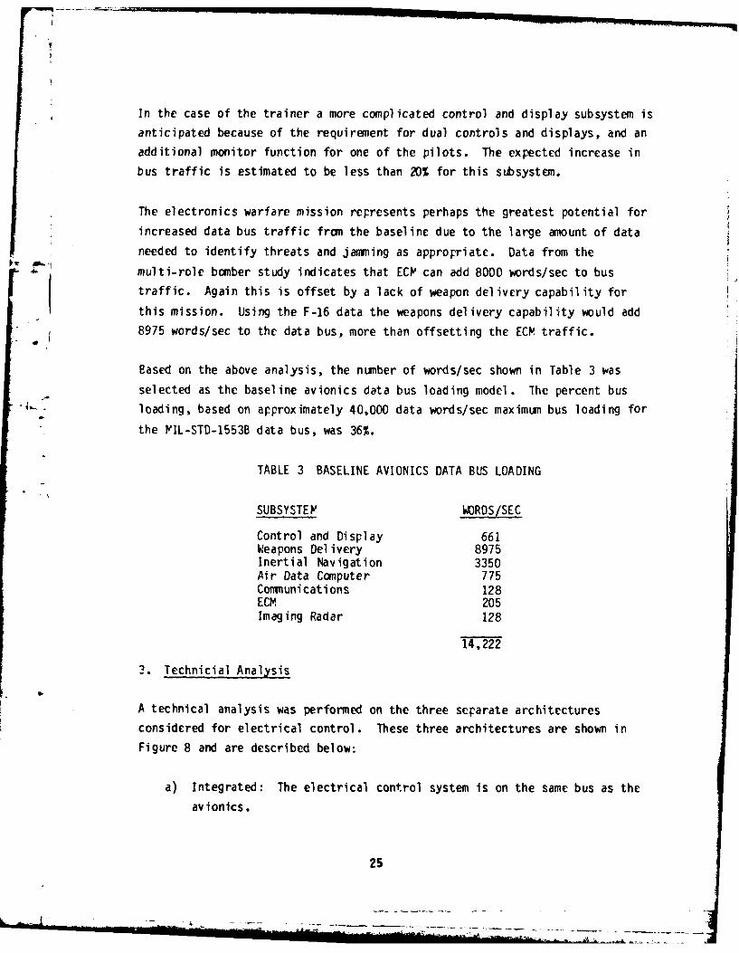
In the case of the trainer a more complicated control and display subsystem is
anticipated because of the requirement for dual controls and displays, and an
additional monitor function for one of the pilots. The expected increase in
bus traffic is estimated to be less than 20% for this subsystem.
The electronics warfare mission represents perhaps the greatest potential for
increased data bus traffic from the baseline due to the large amount of data
needed to identify threats and jaming as appropriate. Data from the
• ' multi-role bomber study indicates that ECIP can add 8000 words/sec to bus
traffic. Again this is offset by a lack of weapon delivery capability for
this mission. Using the F-16 data the weapons delivery capability would add
8975 words/sec to the data bus, more than offsetting the ECP traffic.
Eased on the above analysis, the number of words/sec shown in Table 3 was
selected as the baseline avionics data bus loading model. The percent bus'I-- - loading, based on approximately 40,000 data words/sec maximum bus loading for
the IIL-STD-1553B data bus, was 36%.
TABLE 3 BASELINE AVIONICS DATA BUS LOADING
SUBSYSTE' WORDS/SEC
Control and Display 661Weapons Del ivery 8975Inertial Navigation 3350Air Data Computer 775Communications 128ECM 205Imaging Radar 128
14,222
3. Technicial Analysis
A technical analysis was performed on the three separate architectures
considered for electrical control. These three architectures are shown in
Figure 8 and are described below:
a) Integrated: The electrical control system is on the same bus as the
avionics.
25

1553B BUS
AVIONIC POWERPROCESSOR(S AVIONIC PROCESSOR POWER
RT' s RT's
A: INTEGRATED ARCHITECTURE
1553B BUS
AVIONIC POWERPROCESSOR(S) AVIONIC PROCESSOR
RT's
POWERRT's
B: HIERARCHICAL ARCHITECTURE
15538 BUS
' ..............
POWERPROCESSOR 'POWER RTIs
C: iNON-INTEGRATED POWER BUS
Figure 8 Data Bus Architecture Configuration
26

b) Hierarchical: The electrical control system is on a separate bus but
is connected to the avionic bus through an interbus processor.
c) Non-Integrated: The electrical control system is not connected to the
avionic system by any multiplex data bus.
For each of these architectures the following analyses were performed:
a) Processor loading: This is calculated as the total time required to
calculate the necessary set of logic equations in a minor cycle
divided by the time in a minor cycle. The accepted limit for
processor loading is 50%.
b) Bus Loading: This is calculated as the time required to transmit the
necessary set of data, including overhead, in a minor cycle divided by
*the time in a minor cycle. The accepted limit for bus loading is 50%.
c) Memory Requirements: The total memory requirements for the logic
equations and the executive is calculated.
d) Reliability: An architectural reliability for comparison of theintegrated and hierarchical concepts is calculated.
e) Number of Processors Required: An estimate of the total number of
processors is given for each architecture.
f) Smart RTs: The effect on processor loading and bus loading is
analyzed using distributed processing with smart RTs.
a. General Assumptions
The analysis of the three data bus architectures was made based on the
assumptions listed below. The assumptions (a) through (j) apply to all of
the three architectures studied, whereas (k) through (n) apply only to the
integrated data bus architecture.
27

a) Response time is defined to be the time required for a data change in
one RT to be received by the processor, processed, and transmitted to
all other RTs that require the data.
b) Bus 1/0 and processing are bimodal to meet separate response times of
50 msec and 300 msec. The messages that require a 50 msec response
time are 5 percent of the total.
c) The system uses a FIL-STD-1553C multiplex data bus.
d) All bus transmissions are terminal-to-controller or controller-to-
terminal. These are no terminal-to-terminal transmissions.
c) All bus transmissions are synchronous.
f) The system runs at 128 minor cycles per second. This provides 7.8125
msec in each minor cycle.
g) All remote terminals in the system receive the minor cycle
synchronization mode code each minor cycle.
h) All data words transmitted on the bus are packed 12 data bits per 16
bit word. This will allow expansion of 4 bits per word.
i) For each architecture, there is one power system processor. This
processor is a MIL-STD-1750 machine with 128 K words (16 bits each) of
memory.
j) For each architecture there are ten power RTs. This includes 5 ELYCs.
In the smart RT configurations, the 5 ELVCs will have a Z8002
microprocessor as the processing element.
k) The power system processor is a remote processor on the data bus. The
bus controller is the avionics processor.
1) All power applications processing will occur in the power system
processor. There will be no power processing in the avionics
processor(s).
28
* * .,--,*-----------------------,-,*---- --.

m) Bus loading for the avionics I/O is 36%.
n) The avionic bus controller processor will send a minor cycle
synchronization mode code to the power system processor and to each of
the power RTs every minor cycle. The bus time required to do this is
included in the avionics bus load.
b. Processor Loading
Processor loading is defined as the amount of time within a minor cycle that
the processor is busy executing application and executive code. The loading
of the power system processor, smart RT with Z8002 microprocessor, and
executive loading are all discussed.
Processor loading was calculated for both dumb RT and smart RT configurations.In the dumb PT configuration the power system processor calculates all
equations. In the smart RT configuration the ELYC RTs calculate the category
II and III equations and the processor calculates only the category I
equations.
Equation calculation is bimodal to meet response time of 50 msec and 300 msec.In a dumb PT configuration, 5% of the calculations are spread over 2 minorcycles to meet the 50 msec response time and 95% of the calculations arespread over 32 minor cycles to meet the 300 msec response time. In a smart RTconfiguration, 5% of the calculations are spread over 2 minor cycles and 95%of the calculations are spread over 16 minor cycles.
In the smart RT configuration, each of the 5 ELMC RTs will have a Z8002
processing element. Cnly the processing time for the 500 SSPC complement wascalculated for the smart RTs. The Category II and III equations are divided
equally between the 5 smart RTs. As with power processor loading, thecalculation of equations is bimodal to meet response times of 50 and 300 msec.The processing load for each RT is 21% with 5% of the processing spread over 2minor cycles and 95% of the processing spread over 16 minor cycles.
Because each of the three architectures requires a different executive, the
29

processing time required by the executive is different for each architecture.
In the integrated architecture, the executive is responsible only for actions
local to the power system processor. It is not responsible for bus control
or system actions. In the hierarchical and non-integrated architectures, the
power system processor will have an executive that is responsible for both
system actions and local actions. In addition the hierarchical powerprocessor executive will have slightly more processing requirements as aresult of being a remote on the avionics bus. In relation to one another, thehierarchical executive will require the most overhead, the non-integrated
executive is second and the integrated executive will require the least.
* The actual percentage of processor loading during a minor cycle required by
the executive is dependent on the type of executive as stated above, and onhow the applications software is structured and the amount of executiveservices the application software requires. The more applications tasks there
are, the more overhead the executive requires. A general assumption is thatthe executive overhead for servicing applications tasks is about 20% of the
applications processor load.
c. Data Bus Loading
Data bus loading is defined as the time required to transmit the requireddata, including overhead, divided by the total time available. The overhead
included in the bus loading analysis is inter-message gap time and message
response time. Bus loading was calculated for dumb and smart RTconfigurations in each of the three architectures for the four different SSPCcomplements. The data bus 1/0, like the processor loading, is bimodal to meet
response times of 50 and 300 msec.
d. Pemory Requirements
Estimates of memory requirements were made for the power system processor and
for a smart RT. The elements that are competing for memory are listed asfollows:
30

o xctbecd o apiain qain
oot executable code for application qain
o application datao executive code
o executive data
The memory requirements for equation calculations can be determined exactlybut only estimates can be made for the others. The memory requirement for theequations was determined by coding representative equations in the J73/1higher order language.
Other executable code for applications includes such things as control logicfor the equations themselves and applications processing other than equations.The memory required for this is totally dependent on the design and structureof the appl icat ions software and cannot be accurately determined here.
Estimates can be made, however, for the memory requirements of the executiveand the executive data base. The poiwcr system processor in each architecturetype will require a different executive size and executive data base size.
Estimates on the executive size are: 3000 words for the integrated powerprocessor, 7000 words for the hierarchical processor and 5000 words for thenon-integrated power system processor. The executive data base is dependent
on the type of executive and the structure of the application software. Alarge number of application tasks, events, etc. results in a larger executivedata base. A conservative estimate on the size of the executive data base for
an average set of applications tasks is 5000 words.
e. Reliability
Reliability comparisons for the three architectures are made using the
* generalized reliability model. Reliability computed is not an overall systemreliability. It is a computer architecture reliability and its main purpose
* is for comparison of the three architectural configurations.
The following assumptions were used in the reliability analysis:
31

a) 2.5 HR mission time for the tactical two engine airplane.
b) Processor IFIBF - 3000 HRS: This Y1BF was obtained from the DAIS
AN/AYK-15A specification in Reference 9.
c) GCU M1BF - 4000 HRS: obtained from Reference 5.
d) ELC MTBF - 1159 HRS
e) RT PTBF - 2354 HRS
f) Connector MTBF 1.8 x 10⁶ HRS
Assumptions d-f are based on Harris Corporation hardware experience.
The reliability for the respective architectures was calculated and is shown
below:
Non-integrated - 0.984
Integrated 0.976
Hierarchical - 0.976
Due to the high reliability of the connectors and since an equal number of
elements are connected to the data bus for both the hierarchical andintegrated architectures, the reliability is the samc for these two
configurations.
f. Results of the Technical Analysis
The major conclusions of the technical analysis performed on the three
architectures are:
a) Processor loading: Smart ELCs and an integrated architecture are
necessary to meet the processing requirements for a two engine tactical
aircraft.
b) Bus loading: All architectural concepts can meet the two engine tactical
aircraft power system control requirements if smart ELMCs are used.
c) M/emory: Smart ELMCs will require 17% more memory than the dumb ELYC
configuration to meet the equation processing requirements.
32

d) Reliability: The hierarchical and integrated architectures have identical
reliability due to the high reliability of connectors.
4. Economic Analysis
Both software and hardware costs of a two engine tactical aircraft electrical
power control system architecture were examined. Software costs are for
application software development only. These costs are independent of the
architecture chosen. Hardware costs are relative to the baseline non-
integrated architecture. Only relative hardware costs were obtained since
absolute costs from the manufacturers could not be obtained for the hardware
at this early stage of developnent. The effects of SSPC count and
* I architectural differences were included in the analysis.
All architectural configurations studied have identical numbers of ELMCs, RTs,
4and OCUs. The major differences between the three concepts are in the
processor reuirements.
The requirements for the power system processor for the non-integrated
architecture approach can be met by the DAIS AN/AYK-15A machine both in terms
of hardware and software. The requirements for the power system processor for
the integrated architecture approach can also be met by the DAIS AN/AYK-15A
except that the executive software will not be as extensive since here the
avionics processor will have most of this responsibility. Thus, the software
requirements for the integrated architecture processor will be 20% lower thanthat of the non-integrated architecture processor. This results in a cost
reduction for the integrated architecture system over the non-integrated
architecture system.
For the hierarchical architecture additional hardware and software will be
required to provide the AN/AYK-15A processor with the capability to interface
with two data buses and perform the interbus communications in addition to the
power system processor functions. The interbus communication will result in a
40% increase in processor executive software requirements. This will,
therefore, increase the cost of the hierarchical architecture processorhardware and software over the non-integrated architecture processor.
33

Therefore, the hierarchical architecture system will cost more than thenon-integrated architecture system. From an economnic standpoint theintegrated data bus architecture concept is considered most appropriate for atwo engine tactical aircraft.
5. Conceptual Design
Three power control system data bus architectures were configured using DAIS
concepts to the maximumz extent possible. In order to examine the feasiblityof integrating the power system control function into the DAIS architecture,
two conceptural designs were configured which have varying degrees ofintegration with the avionics data bus. In the first design, the integrated
concept, both avionics and power system control is accomplished using a commnondata bus. In the second design, the hierarchical concept, a separate data bus
is used for the avionics and the power system control. The power systemprocessor is connected to both the avionics and power data buses and performsthe additional function of interbus processing.
The third design is the dedicated or non-integrated power system controlconcept. In this arrangement the avionics and power system control functions
are totally separate with a separate deta bus for each. Such an architecture
probably could not be justified for a light tactical fighter. However, thisconcept was used as a baseline for comparing the two approaches described in
the previous paragraph and for determining power system cotrol requirements
for a light tactical aircraft.
a. Data Bus Architectures
All the data bus architectures presented in this section are based on the DAIS
configuration. The DAIS architecture consists of federated processors
commnunicating with each other and the other system elements (sensors, weapons,
and controls and displays) through a standarized multiplex data bus.Centralized system single-point control is performed by a processor residentsoftware executive that can be relocated for redundancy. Applicationssoftware is structured to provide modularity, reliability, and transfer-
ability. This system architecture is flexible to accommodate a wide variety
34

of avionics configurations, missions, and sensors, which provides redundancyto improve availability, and accommiodate changes in technology.
The basic architecture is designed for a broad class of configurations wherethe number of processors can be reduced or enlarged depending upon theavionics and mission requirements. Standardization, modularity, andapplication independent executive software allows adaptability of this
architecture to a broad class of different applications as well as to making
mission-to-mission changes in a particular aircraft.
Sensors, weapons, and other subsystems are selected as required for theparticular mission and connected to the interface modules of the remoteterminals of the multiplex system or connected directly to the multiplex bus.
b. Non-Integrated Data Bus Architecture
The baseline non-integrated data bus architecture is shown in Figure 9. Theconfiguration has two GCUs, 3 RTs, 5 ELMCs and one DAIS type processor. Powermanagement and control software resides in this processor. In the case of asmart ELI"C saune of this software is moved to the ELtMCs.
The major advantages of this architecture as compared to the other two
candidates are:
a) simple system integration and test - due to the separation of avionics
and power control functions.
b) easily expandable with minimum soft'are impact - due to similarity with
DAIS concept and existing software and hardware modularity.
c) minor changes to existing DAIS software - existing software for DAISwould be "off the shelf" and only an application software package needs
to be written.
The major disadvantages of the non-integrated architecture are:
35

- U,
D-0~
I-,I
9- l
AC w
dA.
*10
C2C
* ca
ca.
36

a) redundant avionics RT interfaces - because both buses are physicallyI. separate, avionics signals needed in power system management would haveto have duplicate interfaces on each data bus.
b) additional controls and displays - since there is no data path between
the avionics and power control systems, multi-function controls anddisplays already developed for the DAIS concept could not be utilized.
c) higher bus loading - because avionics signals from the avionics buscannot be used, these must be obtained by duplicate interfaces.
d) additional weight - due to redundant DAIS components like the controls
and displays and bus interface hardware.
c. Integrated Data Bus Architecture
-The integrated data bus architecture combines the avionics and power systemprocessors on a single data bus. This concept is shown in Figure 10. The
avionics processor acts as the bus controller for the entire data bus and is
otherwise dedicated to avionics functions. The power system processor sharesthe same 1553B data bus and manages and controls its 5 ELMCs, 3 RTs, and 2GCE~s. Controls and displays are shared both by the power and avionics system.
The major advantages of this concept are:
a) minor changes to existing DAIS concept - in this configuration the rowersystem processor acts as an RT and all executive software would be "1off
the shelf". Only a power system application software package needs to bedesigned.
b) least rower and weight - when compared to the other two concepts, theintegrated approach minimizes the redundant use of DAIS software andhardware.
c) less memory requirements -due to the fact that the power systemprocessor is an RT on the avionics data bus, a full executive is not
necessary.
37

c4~c
1'.60
64 AL
4-)
cc '-4
tj tna)_____ 3c i
-I-Ln Q ft
,- jx 38

The major disadvantages of the integrated concept are:
a) interaction of the power and avionics systems - changes to either system
can effect the other as the bus traffic has a fixed limit of 1 megabits
per second. Also response time requirements for both systems must beconsidered in designing data bus protocol and message handling.
b) less expandability - a single DAIS type data bus can be expanded to
accommiodate up to 32 elements maximumi.
d. Hierarchical Data Bus Architecture
The hierarchical concept is shown in Figure 11. The key difference betweenthis arrangement and the previous two concepts is that the power system
processor is connected between a separate avionics data bus and power systemdata bus. The power system processor is a remote terminal on the avionics bus
-but a bus controller on the power system data bus. The numnber of Rl's, ELMCs,and OCUs needed in order to accommnodate the power system control requirementsis the same as in previously discussed architectures. The key advantages ofthis approach are:
a) less bus loading - because avionics data can be obtained from a separate
bus, the traffic on the power data bus is reduced.
b) greater expandability - the hierarchical data bus architecture offers
almost unlimited growth potential due to the ability to cascade anynumiber of data buses each communicating with the next via an interbus
processor.
c) independence of avionics and power system - software development canprogress more independently for the avionics and power system since theneed to coordinate response time requirements is almost entirely
eliminated.
The major disadvantages of this concept are:
39

I-
I~in02
IIn
in-
4-,
In-fLa
6444Lj)
*-0-
40w

a) immature software/hardware: both the interbus processor and its
executive software for interfacing to tvwo data buses is still in
development.
b) added weight - more bus interface circuitry and pover supplies will be
necessary for multiple 1553B data buses than in an integrated approach.
c) higher executive overhead - a single power system processor configured to
be both an PT on the avionics bus and the bus controller on the power
system data bus incurs enormous software overhead.
6. Selected Concept for Preliminary Design
Based on the foregoing, an integrated avionics and power system architecture
using a single data bus system was selected for the preliminary design. The
system will consist of separate avionics and power system processors, 5 EIYCs,
3 RTs (for power system). The avionics processor will handle the system
overhead and perform the bus controller functions. This system will manage
and control an electrical system for a light tactical two-engined fighter
aircraft with multimission capability.
The electrical system consists of two 60 kVA engine-driven generators, one 20
kVA auxiliary generator, three 100 A 28 VDC TRUs and 500 SSPCs. Software for
this system will use the JOVAIL J73 higher order language.
The selection of the integrated architecture is based on the assumption that
avionics bus loading including overhead will not exceed 36% of total capacity
of a tdIL-STD-1553B data bus. Al so that the total number of avionics and power
system elements attached to the data bus will not exceed 32.
41
41

SECTION III
ADVANCED AIRCRAFT ELECTRICAL SYSTEM PRELIMINARY DESIGN
1. Power System Configuraticn
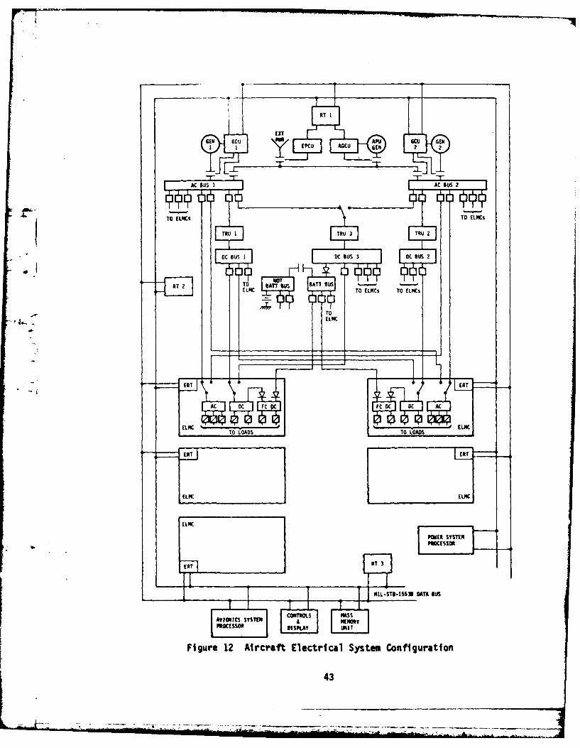
The aircraft electrical system consists of an electrical pover system and an
electrical control system. The electrical system configuration is shown in
Figure 12. The electrical power system consists of two primary generators
which operate in the isolated mode. The two main AC buses are connected by an
AC tie bus which normally is open. External pover (during ground operation)
and the auxiliary generator are connected to the tie bus through contactors
and can provide power to both of the main AC buses. Three TRUs provide DC
power to the system. Cne TRU is assigned to each of the two AC buses and the
-" third TPU is powered by either PC bus. The DC system is designed to provide
- power to a triple redundant fly-by-wire flight control system, thus the threeTRUs. A battery is used to provide emergency power and also to provide
uninterruptible power to the fly-by-wire flight control system.
The electrical control system consists of a power system processor (PSP) and 5
ELVCs. Electrical power to the loads is distributed from the ELICs. Housed
ir the ELIVCs are solid state power controllers (SSPC) which control power to
individual loads and also provide load feeder fault protection. The ELMCs
also contain an imbedded electrical remote terminal (ERT) that interfaces to
avionics sensors, controls the SSPCs, and provides data processing capability.
Load control equations are solved in the ELMCs based on data received from the
PSP. 'Each SSPC has a load control equation.
Three RTs are allocated to the electrical power system. These are DAIS type
RTs which provide for discrete digital and analog data input and output for
the system. The RTs provide the data bus interface for the system's relays
and electromechanical power controllers. In addition, the RTs provide the
data bus interface for the external power control unit (EPCU) end the
auxiliary generator control unit (ACCU).
42
4.-.,
TTO LK-
RT 2 TOSBATT BUS BATT BUS
ELKIC TOSTIN £ TO ELOP
TOPLYLIi
Figure12 A~rraft EectricL Sse ofgrto
z i!T 6 4EE43

The GCUs for the main generators provide protection and control for the
generator, main AC bus, AC feeders to the ELVCs, and any loads on the main AC
bus. The CCUs have a built in data bus interface unit. Gencrator and bus
status information is sent to the PSP from the GCU. The PSP sends the GCUs a
limited amount of command signals; however, the CCUs will operate
independently of the bus.
The ACCU provides control and protection for the auxiliary power unit (APU)generator and control for the auxiliary power contactor. The AGCU interfaces
the data bus through one of the RTs. The basic AGCU functions operate
independently of the data bus. The bus is used to transmit system andgenerator status between the ACCU and the PSP.
The EPCU, like the ACCU, interfaces the data bus through one of the RTs. The
EPCU controls the external power contactor and monitors the quality of
external power.
a. System Characteristics
Primery power for the electrical power system is provided by tw 60 KVA,
115/200 V, three-phase, 400 Hz generators operating isolated. 28 VDC is
provided by three 100 amp transformer-rectifier units (TRU). The DC system
provides the power for the flight critical equipment. A battery is provided
for emergency power and for "gapless" power where thE battery is diode
parallelled with TRU power. AC and DC power are distributed to the loads by
SSPCs contained in five ELMCs.
A flight operable APU generator is provided for emergency and ground
operation. In addition, the system is designed to accept external power
during ground oper 1 tion.
The equipment complement list for the electrical power system is shown in
Teblc 4. The PC and DC power system configuration is shown in Figure 12.
This figure shows the distribution of power from the generators to the ELM Cs.
Dual redundant feeders are provided for each ELFC.
44

TABLE 4
ELECTRICAL SYSTE' EQUIPMENT LIST
2 - Primary Generators, 60 kVA, 115/200 V. 400 Hz
I - APU Generator, 20 kVA, 115/200 V, 400 Hz
3 - TRUs, 100 amrs, 28 VDC
1 - 24 VDC Battery
5 - ELIFCs, 100 SSPCs/ELIC
3 - RTs (DAIS)
2 - GCUs (main generators) %ith bus interface
I - APU GCU with RT interface
1 - EPCU with RT interface
I - Power System Processor (DAIS)
(1) AC System
The primary AC power is provided by two 60 kVA generators. A tie bus is
provided between the main generator buses. Since the generators operate
isolated, the bus tie breakers (BIB) remain open during normal flight
operation. The BTBs are closed during one generator operation or wthen
external power or auxiliary power is used.
Two sets of PC power feeders are brought into each ELF'C, one set from each
generator bus. The ELIC selects ore of the sets of feeders as a source of
power for the AC loads. Both sets of AC feeders are "hot".
The AC feeders are protected by EYPCs. E .PCs are controlled by the GOCUs.
The generator, the generator bus, and the AC feeder Et.PCs are controlled and
protected by the GCU which is described in section III.1.a.(5).
(2) DC System
The DC system is designed to provide power to a triple redundant fly-by-wire
flight control system. Three 100 amp TRUs provide the DC rower. A battery is
45

F.1 I
ja ____
L
* 2 _______
460

used for emergency power and to provide power to the flight critical buses
during bus switching.
The three TRUs arc powered from the two main generator buses. One TRU is
dedicated to each main generator bus. The third TRU is powered by either main
generator. A relay is provided which allows the third TRU to be powered by
either source. The TRU buses are isolated. With this configuration,
transients xccurring on a bus are isolated from the rest of the system. This
represents a change from the original DC configuration shown in Figure 4.
DC power to the loads is distributed from the DC buses within the EVIYCs. Each
of these DC buses has two sources of power available. he ELVtC central
processor controls the selector relay. In the event of loss of power on the
primary feeder (one feeder is designated as the primary source), the ELIVC DC
bus will be powered by the other feeder and source.
A battery is provided for emergency power (until the APU generator comes on
line) and to provide power to the flight critical bus during bus switching
outages. The battery is connected to the Hot Battery Bus. Emergency loads
such as emergency cockpit lighting are powered from the Hbt Battery Bus. The
Hot Battery Bus is connected to the Battery Bus by a contactor which is closed
in normal operation. The Battery Bus is connected to DC Bus 3 through a diodc
which prevents current from flowing from the Battery Bus to DC Bus 3.
The DC system provides power to the fly-by-wire flight control system. Flight
critical buses in the ELPCs distribute power to the flight-by-wire equipment.
The flight critical buses are powered from the DC bus in the ELVC and also
from the Battery Bus. These two sources are diode parallelled. The Battery
Bus provides po ".- r to the fly-by-wire equipment during power outages and
* during bus transfers.
(3) External Power
The system can be powered by an external AC power source. External power is
applied to the AC tie bus through the external power contactor. Application
47

of external power to the main PC buses is controlled by the GCU through its
respective BTB. The EPCU provides control and protection of the external
power. From the main AC buses, the external power is distributed the same way
as for aircraft power.
(4) Auxiliary Power
A flight operable .PU generator provides backup power to the main generators.
The APU generator is connected to the AC tie bus through the auxiliary power
contactor. Control and protection for the APU generator is provided by the
ACCU. Like the main generators, the APU generator operates in the isolatedmode. At no timc is it parallelled with any other source.
(5) Cenerator Control Unit
-To provide the necessary response time for control of an aircraft generator,
control and protection of the generator is accomplished by the CCU and is not
delegated to the PSP. The GCU also provides control and protection for the
main AC bus. The GCU is connected directly to the data bus; however, the
generator control and protection functions operate independently of any bus
service functions. This isolates the generator system from data bus failures.
During system powerup, the GCUs bring the power system on line before the
control system is functioning. A functional diagram of the GCU is showif in
Figure 14.
Protection
An important function of the CCU is to protect the generator system from
faults and to protect load equipment connected to the system from"out-of-limits" electrical power quality. The calibration and operating time
delays of the various protective circuits will selectively isolate faults with
a minimum reduction of generating capacity and a minimun interruption of power
to airplane loads. The OCU protective functions are listed below.
48

DATA BUS
La
'hi-
t.n
ix sS
- ro-
cz 2r w *1w i
LuL
wh 'a cr. "4 C
w )I- i u--
a uj - ca4CI
dn L6 l. IZ c
is -Ccal
o4

Function
Overvol tage
Undervol tage
Overfrequency
Underfrequency
Open Phase
Differential Fault
Failed Rotating Rectifier
Overload
Tie Bus Fault
Control
The control function of the GCU provides generator excitation and voltage
regulation. In addition the GCU controls the generator circuit breaker (GCB)
and the BTE.
Discrete I/O
The GCU accepts discrete input and discrete output signals for transmission to
and from the PSP. In this function the GCU performs like a remote terminal.
Thc AC ELMC feeder controllers and any load controllers on the main AC bus
will interface the PSP through the GCUs discrete I/O.
b. System Operation
The electrical system is designed for automatic operation with manual
override. Control of the system is distributed among the PSP, GCUs, and ELMCs.
As shov.n in Figure 13, each PC and DC bus in the ELMC has two sources of
power. The sources are designated primary and secondary. In Figure 13, the
selector relays in the ELMCs are shown in their primary positions. The
selector relay for TRU 3 is also in the primary position. The system
contactors are shown in their normal flight positions.
50

Critical to the operation of the electrical system are the GCB and BIB of each
generator channel. Both are under immediate control of the GCU. The GCB will
not close with the BIB closed; however, with the GCB already closed, the BIB
can be closed. The GCB will close automatically when the generator power is
within specified limits. The GCB will open when the power is outside theselimits. If a GC opens, the respective BTB will close and the BTB of the
other channel will close. If the BIB and GCB are open and voltage is present
on the tic bus, the BIB will automatically close. GCB operation will have
priority over BIB operation. If the BIB is closed, it will automatically open
if the GCP needs to be closed.
(1) Startup
The startup of the electrical system from a "dead" system is accomplished in
two phases. In the first phase, the power generation system is brought online. In the second phase, the control system is brought on line. Startup of
the power generation system is controlled by the GCUs. W'hen the APU generator
or external power is involved in the startup process, the GCUs and the AOCU or
the EPCU control the startup. The control system starts up when power is
applied to the control system components (power system processor, electrical
remote terminals, etc.) and the software is initialized. Figure 15 shows the
startup of the complete electrical system from any one of the three sources
available, main generators, auxiliary generator, or external power.
The startup of the power generation system is centcred around the operation of
the system contactors and relays. Figure 16 shows the operation of these
contactors and relays during a system startup with the main generator.
Generator 1 comes on line first, that is, engine No. 1 is started first.
After engine No. I is started, engine No. 2 is started.
Once the power generation system has been powered up, the control system isstarted. The information system startup/restart function is performed with
the assistance of a startup program resident in each system processor's read
only memory (ROP,), a system loader and the master executive.
The pilot controls the system startup/restart process via the Processor
51

GENERATOR EXTERNAL API) GENERATORSTART POWER ON START
EPCU AGCUPOWER UP POWER UP
GCUPOWER UP
AC BUSPOWER
DC BUSPOWER
* ELMC- POWER UP
' NC SSPCsPOWER UPLADS
POWER UP:AVIONICS PROCESSORPOWER SYSTEM PROCESSORSYSTEM MASS MEMORYREMOTE TERMINALS
FINITIALIZE
AVIONICS PROCESSORI
INITIALIZEPOWER SYSTEM PROCESO
INITIALIZEELMC/ERT
AI RCRAFT,,POWER UP
Figure 15 Electrical System Startup
52

.I . . . . . . I.-0n L ... ... . . . .. . . . . . . . .. . . .
*1 I
ii4--0U.
06
, 0.
C
2I
~II
53!
53-

i-I'Omni%
Control Panel (PCP) as shown in Figure 17. The bus power switch allows the
pilot to enable or remove power to the multiplex equipment. The processor
rower switches allo., the pilot to enable or remove power to the processors.
The GROUND position of the startup switch permits the pilot to specify initial
startup as opposed to a restart, indicated by the INFLIGHT position. The
start button permits the pilot to request the use of mission software already
loaded, while the LOAD button allows the pilot to force the reload of all
mission software.
In addition to the pilot initiated restart, the system shall perform automatic
restart or system warm start. Warm start is primarily in response to a system
power transient, and the objectivc is to get the system back up and running as
- Iquickly as possible. The procedure is to warm start the mission software in
the processors and not perform a reload, if possible.
The startup/restart procedures are specified in VP 221 200 (Reference 10) and
included the following functions as shown in Table 5: hardware self tests,
bus control arbitration, configuration identification, mission software
verification and reloading (if required), and system cold or warm start
initialization.
(2) Steady State Operation
During steady state operation, the control system constantly monitors the
state of the power system and the loads. Status information is fed into the
system and load control equations. The solutions to the equations are
transmitted to the system contactors, relays and loads. lhe control system
gathers and processes data required to turn loads on and off.
(3) Cenerator Failure and Faults
System operation during a generator failure is shown in Figure 16. Generator
failure operation begins under "GEN I FAILURE." After GCB1 trips, BTBI
automatically closes. BTB2 closes upon command from the pcwer system
processor. The ELIVC and AC and DC bus selectors automatically switch to the
secondary source if the primary source is affected by the loss of generator 1.
Eus switching within the ELVCs, in this case, occurs independently of the PSP.
54

S IDE A -BUS POWER SIDE I
F-rPOCESSOR POWR-
P AVIONICS AVIONICS AVIONICS POWER
~~ IE~II TEST ___
Figure 17 Processor Control Panel

< 40
LA--
04
cl: L.I.
LL- LU A
b--J
_jj
-cc -i
C CL
__ * dc U
LUJ -J3c ~ ~ ~ L ZU W
V) 0) CL I- c2: =0 U =-
0 LU
U)~C La L
I- L&
m.~ -c -J1- j
LOL
4=. C.
m& .Cc La.J U
00 P- u-L0-3 0. P0 0a N4 Kc00D =- alU.J 0- w D-
1D00 = 5--
C. '-456

-,o
All power feeders to the ELMCs are protected by EMPCs. In the event of a
* feeder fault, the EMPC trips the feeder off the main bus. If that feeder
provided the primary power to an ELYC bus, the bus will sitch to the
secondary source.
(4) External Power Operation
External power is controlled by the EPCU. The EPCU closes the EPC when
external power is within the specified limits. A request for external power
turns off the main generator(s) or APU generator, depending on what is
operating at that time, and closes the EPC and BMBs,
(5) Auxiliary Power Operation
The APU generator is controlled by the AGCU. APU generator power is applied
to the tie bus through the APC. The AGCU also provides protection for the
generator and controls the auxiliary power contactor. With no voltage on the
tic bus, the auxiliary power contactor will close when APU generator power is
within specified limits and a request for APU power is present. If the BTB(s)
are open, they will close if the CCE is open. If the GCB is closed, the BTB
will remain open.
(6) Processor and Data Bus Failures
In the event of a PSP or avionics system processor failure, the electrical
generation portion of the system continues to function. The OCUs and the AGCU
function independent of the data bus system. On/off control for the SSPCs
will be lost; however, the SSPCs will remain in the same state as they were
before the failure. The ERT processor will continue to operate, performing
the ELVC power bus switching functions when necessary.
(7) Load Vanagement
Load management is divided into the areas of bus switching and load shedding.
Following is a description of each of these areas for the AAES.
57
. . . . .. 7 : ... .

Bus Switching
The AAES allows for redundant power paths for both AC and DC power. Bus
switching as defined in this section relates to the switching of redundant
power distribution lines which exist between the main AC and DC buses and the
buses located in the ELt.Cs. Control for bus switching resides in two
locations, the ELMCs and the power system processor.
Load Shedding
Load management is achieved through load management routines which are
included as an integral part of the AAES system software. Sixteen levels of
management are available. Each management level allows three possible
variations of the power control equation. The equation may be (1) solved
normally, ((2) have its solution forced to "0" or (3) have its solution forced
to "1. This in effect allows the equation itself to be modified at each
management level
2. Integrated Power System Control
. -- A single integrated data bus system is used to control the electrical power
system. The integrated architecture combines the avionics and power system
processors on a single data bus. A functional diagram of this concept is
shown in Figure 18. The avionics processor acts as the bus controller for the
entire data bus and is otherwise dedicated to avionics functions. The PSP
shares the same 15530 data bus and manages and controls its five ELICs, three
RTs, and two CCUs. Controls and displays are shared both by the electrical
and avionics systems.
a. tultiplex Data Bus Characteristics
The multiplex data bus used in the integrated avionics and power information
system conforms to MIL-STD-1553B requirements. Following is a brief
description of the key requirements of this standard. The bus operates at a
maximum data rate of 1 megabits/sec. The data transferred over the bus is
coded as FPanchester II bi-phase levels. Data words are 16 bits plus the sync
58

U. RI P utl.I '
90 E
lei I
4-)
C0t
43
6-h
two 46'4
9" Ia
'4Milli ;I"a13 oil VI
h'
mo ;1122 Ni a
59U

waveform and the parity bit for a total of 20 bit times as show in Figure 19.Also, as shown in Figure 19, word formats consist of three types: commnand,data, and status.
Sole control of information transmission on the bus resides with the buscontroller, which initiates all transmissions. Commnand words sent by the bus
controller to devices connected directly to the 15538 data bus contain an
optional mode code field as show in Figure 20. These mode codes are shown in
Table 6 and are used by the RT to control information flow.
The commnand, data, and status words defined above are grouped to form messagesfor transmission over the data bus. Allowable message formets are show in
E IFigure 20. No other message formats are permitted.
b. Avionics/Electrical Control System Interface
The multiplex data bus provides the interface between the avionics system andthe electrical control system. The avionics processor controls the data busand as a result, provides overall system synchrcnization and timing.
Information exchanged between the avionics system and the electrical controlsystem includes electrical system startup and shutdown commnands issued by theavionics processor, controls and displays data, and avionics sensor data.
Data that is received from aircraft controls is first interpreted by the
avionics system, and if this data requires processing by the electrical
control system, it is transmitted to the power system processor. Similarly,
electrical control system data that needs to be placed on aircraft displays issent to the avionics processor by the power system processor. Finally, ERTsin the electrical control system may, as part of their function, interface to
avionics sensors. Data collected from these sensors is transmitted directlyto the avionics processor.
c. Electrical Control System
The electrical control system consists of a distributed network of processors,
controllers, and terminals that monitor the electrical power system and exert
60

o~C 91f. . P4 0
DYNAMIC BUS
ci CONTROL
'. SUBSYSTEM FLAG
'0 .- BUSY
c4 'BROADCAST-4 RECEIVED
- ..4
cn In
L n
SERVICE REQUEST
V4 INSTRUMENTATION co
LU U,
in cn
Id Ln q
pMC-
0 a mw
a a
4A W dI
auto
0- tn Ive
A5 CC -4
c~) LU61

Bill!ga
W.-.
1 mc,* as
loI-
*~ i s
in-
tipi62n

TABLE 6 BUS 1MESSAGE MODE CODES
Associated BroadcastT/R Bit Mode Code Function Data Word Command Allowed
1 00000 Dynamic Bus Control No No
1 00001 Synchronize No Yes
1 00010 Transmit Status Word No No
1 00011 Initiate Self Test No Yes1I00 rnmte htonN e100100 vrd Transmitter Shutdown NO Yes10010 OIeriie Tramitter ShutoW No Yes
1 00110 vrd Inhibit Terminal Flag Bit No Yes
1 01000 Reset Remote Terminal No Yes
*1 01001 Reserved No TBD
1 01111 Reserved No TBD
1 10000 Transmit Vector Word Yes No
0 10001 Synchronize Yes Yes
1 10010 Transmit Last Command Yes No
1 10011 Transmit BIT Word Yes No
0 10100 Selected Transmitter Shutdown Yes Yes
0 10101 Override Selected Transmitter Yes YesShutdown
IlorD0 10110 Reserved Yes TBD
I or 0 1111 Reserved Yes B
NOTE: To be determined (TBD)
63

control functions over it. lhe various elements of the electrical control
system communicate with each other via messages transferred on a standard DAIS
1553B multiplex data bus. Control and synchronization of the data bus is
performed by the avionics processor. All electrical control system elements
perform as remote terminals in relation to the avionics processor. Those
elements that make up the electrical control system are the PSP, 5 ERTs, 3
DAIS RTs, 2 GCUs, avionics controls and displays, and a DAIS mass memory unit.
(1) Power System Processor
The PSP provides overall control of the electrical control system. Electrical
system status information is provided to the PSP by other elements in the
- I ielectrical control system. Avionics controls provide updated control and
flight mode information whenever this information changes. The PSP uses this
information it receives to calculate load management priority levels, power
generation and distribution system configuration requirements, and electrical
power request equation solutions. In addition to its control of the
electrical control system during normal operations, the PSP also controls the
electrical control system during system startup and shutdown operations.
(a) PSP Hardware Description
The PSP is anAN/AYK-15A digital processor with 128K 16 bit words of memory.
This processor is described in DAIS specification SA 421205 (Reference 9).
The primary function of the PSP is to provide control and management of the
aircraft electrical system. To accomplish this, the PSP must perform several
functions such as electrical generation network monitoring, electrical load
priority establishment, power request equation solving, and povwer system
startup and shutdown. In addition, the PSP must process requests from the
DAIS 15538 bus controller and handle selected avionics data. A BIT capability
is included in the PSP to insure integrity of the system.
(b) PSP Functional Requirements
Monitoring and cortrol of the power distribution system requires the PSP to
receive status inputs from both the electrical generation network and the
64

ERTs. The electrical generation network consists of all the aircraft
generators, the aircraft external power source, the aircraft battery, and
associated control units. Also included arc both PC and DC poker buses, and
power controllers that provide routing of electrical power from the sources to
the appropriate buses.
Status information received from the electrical generation network includes
data from the GCUs, and the RT that monitors the APU and the aircraft externalpower source. Data received from the GCUs provides generator overload and
failure status and PDS configuration status. Data received from the RT
provides external power source status, and APU overload and failure status.
Each ERT provides AC and DC feeder selection status for its ELVC. In
;. addition, SSPC RESET and TRIP status is sent to the PSP. The flow of PSP
control and status data is shown in Figure 21.
Under normal operating conditions each bus in the elcctrical generator network
has a designated primary power source, and each ELPC has designated primary AC
and DC feeders. Whenever generator failure occurs or sufficient overload
conditions arise, automatic switching of power sources for one or more of the
buses will occur and updated configuration and load status information will be
sent to the PSP. Similarly, if an AC or DC feeder to an ELMC fails, automatic
feeder selection will occur and updated status will be sent to the PSP. If
electrical distribution network conditions cannot be successfully resolved
automatically, then the PSP will override the automatic switching and modify
the electrical distribution network as necessary.
Electrical Load Priority Establishment
Load priority establishment requires inputs from the electrical distribution
network indicating generator configuration and condition. Inputs also must be
received from the ERTs indicating AC and DC feeder selection. This
information, combined with mission and flight phase data, and current state of
the aircraft electrical system is provided to the PSP applications software to
perform the calculations necessary to determine an appropriate electrical load
priority level.
65
~~~~~~~.. . . . .. . . . ......... ......... ........... ... .. .. . ... ... ... . . . .. . ..-

ISPOWERSYSTE
ix cc CoW ULj at
1-~U W~1~ 1-00 *m
84 1- 0 Jj
0GENERATORS (2)
*GCU (2) ELHC (5)
*APU GEN ER*APU GCU
EXTERNAL 0 EXT. POWER INTF. ACFEESsCSLCOS AC LOAD
POWER 9 DC SELECTORS SUPPLIES9 EXT. POWER CONTROL
DC FEEDERS * AC BUSDCLA* EMERGENCY BATTERYDCLAI* DC BUS SUPPLIES
sAC BUS (2) BATTERY 0 SSPCs
*TRV (3) FEEDERS _______
*DC BUS (3)
eBATTERY BUS
*REMOTE TERMINAL
POWED DISTRIBUTION LOAD DISTRIBUTIONSYSTEM SYSTEM
Figure 21 Power System Processor Control and Status Data Flow
66

Power Request Equation Solving
Power request equations are Boolean equations derived from aircraft discretes.
W:henever power is needed for a particular aircraft function, the necessary
power request equations are solved by the PSP applications software and
appropriate power requests are issued to the ERTs for load priority analysis.
Power System Startup
The PSP controls power system initialization in order to insure that system
power up occurs in an orderly fashion so as to prevent damage or failure of
electrical equipment on the aircraft. Functions performed by the PSP at power
system startup include BIT, initialization of ERTs, computation of initial
load priority level, calculation of initial power request equations and
transfer of the initial power requests to the ERTs.
Power System Shutdown
Similarly, power system shutdown must occur smoothly so as to prevent risk ofdamege or failure of aircraft electrical equipment. Power system shutdown
requires the PSP to send final poker requests and a shutdown message to the
ERTs.
DAIS 1553B Bus Controller Request Processing
Bus controller request processing requires the PSP to respond to requests made
by the avionics processor which controls the 1553B data bus. This function
requires the PSP to perform various tasks such as providing controls and
displays data, running BIT, enabling power to avionics subsystems,
communicating with RTs or ERTs, and updating power system priorities. These
tasks are performed by the PSP applications software.
(c) PSP Executive Software
The purpose of the PSP Executive (PSPE) is to provide an interface between
hardware comprising the DAIS federated electrical power control system, and
67

the PSP applications softv~are that executes in the DAIS processor. This
interface permits applications software development without knowledge of the
information transfer system hardware or its operation. Similarly, this allows
hardware modifications to be performed without affecting the applications
software since references to time or to RTs are on a logical level. The PSPE
is basically the same as a standard DAIS single processor synchronous
executive, (DAIS specification SA 221308, Reference 11), except that it does
not perform data bus management, a function reserved for the avionics
processor. The PSPE controls operations peculiar to the processor, including
4" control of the PSP applications software and local participation in the I/O
processes.
The architecture of the PSPE implies a separation of functional components,
control of one component over another, and dependence of one component on
another. The PSPE system architecture is shown in Figure 22 depicting the
separation of hardware and software functions. The PSP applications software
is functionally isolated from the hardware by the executive software just as
the subsystems and EPTs are isolated from the computer by remote terminals and
the data bus, respectively.
The PSPE is a realtime system, in which the activities of the PSP applications
software are coordinated with the passage of real time in the outer world.
The minimum quantum of time to which coordination occurs is known as the minor
cycle. It is possible to specify or determine the time of an action within
one minor cycle, but not to a fraciton of a minor cycle. Thus, I/O
interactions and task interactions may occur, may be known, and may be
controlled within the framework of the minor cycle time unit. This timing is
a requirement for I/O control, synchronization and executive process handling.
In order to successfully control activities of the PSP applications software,
the PSPE performs several functions. These functions include task control,
event handling, compool block handling, executive control, minor cycle setup,
and local initialization. These functions are discussed below.
68

AVIONICS POWER SYSTEMPROCESSOR PROCESSOR
APPLICATIONSOFTWARE
1553 BUSEXECUTIVECONTROL SFWRFUNCTION HARDWARE
BUSINTER FACE
DAIS 1553 BUS
GCUGCUEL14C Soo ELM R R
Figure 22 Power System Processor Architecture With PSPE
69

Task Control
Tasks are processing modules that can be controlled and executed
independently. In order to understand the interactions of tasks, it is
necessary to understand possible "states" that these dynamic processes may
have. At any given instant, each task in the PSPE mission software system has
one of the "states" shown in Figure 23. It should be noted that not all
states are mutually exclusive; in Figure 23, the tree structure shows a
subsettirng relationship with respect to the various states. Thus, INACTIVE
and ACTIVE are both substates of INVOKED, and hence, a task which is INACTIVE
(or ACTIVE) is simultaneously also in the INVOKED state. Similarly, a task
that is SUSPENDED is also INVOKED, ACTIVE, and DISPATCHABLE.
Figure 24 also indicates the method of transition from one state to another.
Figure 24 is another way of showing the state transitions. For example, a
SCHEDULE statement will transfer an UNINVOKED task into an INVOKED state,
while a CANCEL statement will transfer an INVOKED task into an UNINVOKED state.
o Task Hierarchy
- |Any given task may be SCHEDULED by one and only one task, which is called its
controller. All tasks scheduled by a controller are said to be its "imediate
descendants." Any immcdio.L- descendant can, in turn, be a controller for
other tasks. The "descendants" of a task are its immediate descendants and
all of the descendants which they have. The relationships of controller and
descendant define task hierarchy.
o Priorities
At any time, there may be many processes potentially executable. These
include tasks, executive actions invoked by tasks within the processor, and
executive actions invoked by RTs and ELMCs. In order to resolve conflicting
demands on the processor, a system of priorities has been adopted. Tasks are
divided into two classes: normal mode tasks and privileged mode tasks. As a
class, privileged mode tasks and executive actions have a higher priority than
normal mode tasks. Within each class, conflicting demands on the CPU are
resolved as described below.
70

STATES OF A TASK
/ / A\\\
/SCHEDULE\
CANCEL .
UN INVOKED INVOKED
/EVENTS\
/ END
INACTIVE ACTIVE
EVEN4T/ J)
/ WAITWAITING DISPATCHABLE
711
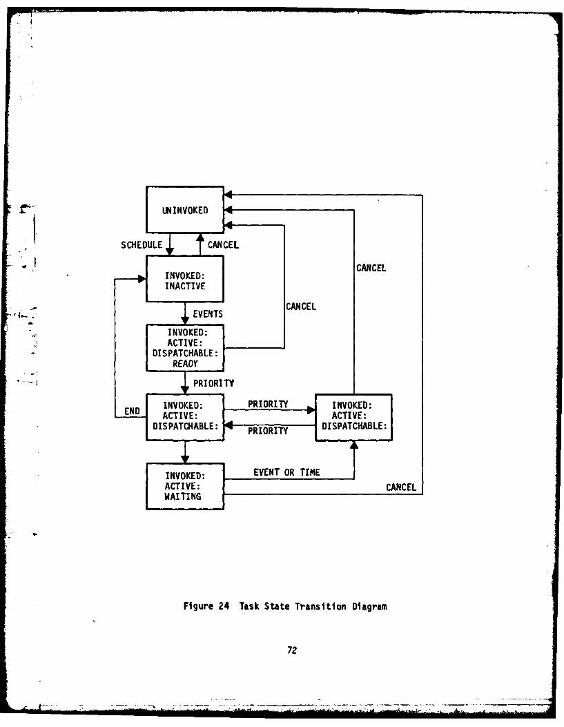
Il . " UNINVOKED T
-.;ULE CANCEL
INVOKED:".. INACTIVE... CANCEL
, I,..2 EVENTS
INVOKED:
ACTIVE:DISPATCHABLE:
READY
.PRIORITY
INVOKED: PRIORITY INVOKD:1END0 ACTIVE: L ACTIVE:IS PATCIIABLE:LEDISPATCHABLE: PRIORITYW I PA C A L
INVOKED:EVENT OR TIME
ACTIVE: CANCELWAITING
Figure 24 Task State Transition Diagram
72

Normal mode tasks are linearly ordered by priority. At any time, if noexecutive actions arc called for and if no privileged mode tasks are ACTIVE,
the CPU executes the highest priority ACTIVE normal mode task. If, duringexecution of a normal mode task, an executive action is called for or if a
privileged mode task or a normal mode task with higher priority becomesactive, the original task is iniiediately placed into SUSPENDED state.
Privileged mode tasks are not ordered by relative priority; instead, they are
executed on a first come, first served basis. When a privileged mode task
becomes ACTIVE, it is executed immnediately. Once a privileged mode task is in
EXECUTING state, it is in control of the processor. It can be SUSPENDED onlywhen it invokes an executive action by means of a realtime statement. Upon
completion of the action, control is returned to the task.
Event Handl ing
An event is a Boolean flag that may be referenced by one or more tasks.Events are used primarily to control the states of tasks, although they mayal so be used simply for communicat ion of Boolean data. A task may SIGNAL anevent, may read the values of an event, may WAIT for an event, and an cvent
may appear in the event condition set of a task. Events are divided into two
classes, explicit and implicit.
Explicit events are named and used by the applications software programmer.
They contain the meaning which is assigned to them. The values of explicitevents are determined solely by their initial state (OFF), and the values
given to them by tasks. Implicit events are associated with certain system
occurrences. Their values are not under the control of tasks, but aredetermined entirely by systemi occurrences with which they are associated.
There are three categories of implicit events, namely task activitation
* events, COMPOOL block update events and minor cycle events.
* Every task has an event condition set, which is used to control its
activation. An event condition set is a collection of conditions, each one of
which has, at any particular time, the value CN or OFF. Each condition alsohas a prespecified "desired" value, either ON or OFF. When all the conditions
73
_____

of a task which is INVOKED but INACTIVE have their desired values, the task is
activited (i.e., made ACTIVE). A task may have a null event condition set, in
which case it can be INACTIVE only momentarily.
COPPOOL Block Handling
CCMPOOL blocks are data agglomerates used for communication between separate
tasks and for communications between tasks and the external environment (i.e.,
RTs and ERTs). CO',POOL blocks are divided into three categories: input,
output and intertask. Input COPPOOL blocks are used to input data from RTs
and ERTs, which may then be used by tasks. Output COMPOOL blocks are set by
tasks, and their values are output to PTs and ERTs. Intertask COMPOCL blocks
; ( are used for communications between tasks.
Since a COMPOOL block has a global copy in the processor, and also, possibly,
a virtual copy in an RT or ERT, it is necessary to send COMPOOL update
messages across the data bus to maintain consistency between the copies.
CO :POOL blocks are classified as synchronous or asynchronous.
The various categories of COMPOOL blocks, and the ways in which they may be
referenced by tasks, are shown in Table 7.
Table 7. CATEGORIES OF COP-POOL BLOCKS
CATEGORY SYNCHRONOUS ASYNCHRONOUS
INPUT May be used in many tasks. Not used.
OUTPUT Fay be set in one task. Not used.
INTERTASK Pay be set in one task. Pay be set in many tasks.Used in many tasks. Used in many tasks.
Executive Control
The PSPE controls the state of realtime entities existing within the
processor; specifically, tasks, global copies, and copies of events. The local
executive control function is invoked at all points when a decision must be
74

made regarding what to process ne-xt, namely when an executive service has beencompleted. If no minor cycles are pending processing, then the local
executive dispatches the highest priority DISPATCHABLE task. When a task has
completed execution, it returns to the local executive control function. At
this point, the task is set INACTIVE, and its activation event, if any, issignalled OFF. Then the task's event condition set is evaluated and the taskis reactivated if all conditions are satisfied.
Local Initialization
Local initialization sets the time and minor cycle count to zero, andinitializes internal variables indicating the executive state to null values.
Processing of hardware errors is perfonned,and control is returned to the
master sequencer routine.
4 (d) PSP Applications Software
The PSP applications software resides in the power system processor andexecutes under control of the PSPE. Functions performed by the PSPapplications software include the following:
Power system startup
Power system shutdown
Electrical load priority establishmentPower request equation solving
Bus message processing
ERT status processing
Power distribution system configuration controlControls and displays data handling
In order to perform its functions, the PSP applications software conmmunicateswith other elements in the DAIS federated architecture that comprises theaircraft electrical control system. The relationship and data flow betweenthe PSP applications software and the other system elements is shown in Figure25. As showni in Figure 25 the PSP applications software commnunicates with theavionics processor, generator control units, ERTs and electrical system Pis
75

POWERSYSTEMPROCESSOR
PSPAPPLICATIONSSOFTWARE
* AVIONICS P BUS CONTROLPROCESSORMESSAGES 0 AVIONICS
PROCESSOR
* DISPLAY MESSAGES- DATA * CONTROLS DATA
GENERATOR•CONTROL 00 0 GCU COMANDS UNIT (2) * GCU STATUS
* GENERATOR CONDITION. GENERATOR
CONFIGURATION
I ELECTRICAL ILOADM ANAGEMENT
* LOAD MANAGEMENT CENTER (2) 0 POWER DISTRIBUTIONLEVEL I NETWORK STATUS
0 SSPC POWER REQUEST • AIR VEHICLESUBSYSTEM STATUSe AIR VEHICLE SUBSYSTEM
DATA REQUEST 0 SSPC STATUS
RREMTE e SSPC TRIP
" ITERMINAL STATU0 " RT INPUTS RI NA (3 RT STATUS
Figure 25 PSP Architectures Software Data Flow
76
- - -- -- - - - ~

via a DAIS 1553B data bus. The interface between the PSP applications
software and the data bus consists of the PSPE, and the power system processor
bus interface hardware. Functions performed by the PSP applications software
are described below.
Power System Startup
The power system startup software module performs functions necessary to
insure an orderly power up sequence of air vehicle equipments. First of all,the PSP applications software is initialized and an initialization message is
sent to the ERTs. Next, initial power distribution system information, and
aircraft mission and flight phase information are processed to determine an
initial electrical load management priority level. This load management levelis then sent via the 1553B data bus to the ERTs. Finally, initial power
request equations are solved and requests for power are transferred to the* .ERTs.
Power System Shutdown
The power system shutdown software module sends equipment power off requests...-.. to the ERTs to insure an orderly shutdown of aircraft electrical power systems.
Electrical Load Priority Establishment
The load priority software module determines an appropriate electrical loadpriority level based upon generator configuration, generator condition, ELMC
power bus connection, current state of the system and aircraft mission and
flight phase. W.henevcr any of the above conditions changes, load management
level equations are solved to provide a correct load management level which is
then sent to the ERTs. There are 16 possible load management levels. Load
- -management level selection is depicted in Figure 6.
Power Request Equation Solving
Power request equations are of thf Z=R where R may take one of the
following forms:
77

Form 1 One variable of the form A or A~, or the value"logic 1"#
Form 2 Five variables arranged in any valid Boolean
expression with each variable used once, only
Form 3 Twenty variables arranged in any valid Boolean
expression with each variable used once, only
riForm 4 Two hundred variables arranged as the sum of
products with each product term composed of no more
than six variables with no variable repeated in the
Boolean expression
There will be approximately 208 form 1, 236 form 2, 45 form 3, and 8 form 4
equations for this aircraft . Figure 26 shows an example of how typical power
request equations are derived from various airplane discretes. Power request
equations are solved by performing required Boolean operations on the equation
parameters. After the equations are solved, results are sent via the 15538
data bus tc the appropriate ERT where the results are used for computing load
control equations.
Bus IFessage Processing
The bus message processing software module receives messages from the DAIS
15538 data bus, determines the message function and calls the appropriate
software module to process the message. Bus message types and appropriate bus
message processing actions are described below.
o Request avionics data
Call avionics data handling module to collect appropriate avionics
data from power system P15.
o Request displays data
Call controls and displays module to send displays data to
avionics processor.
78
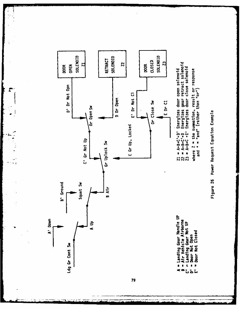
C 0 J3 0
CC Ji I...J 0 0 .- i ft 0
cOS 4 0W 4A, 0.
0n- 0 (A
0 41 (A
W 4 J 0 0~
C 0 L.U 404' -- 1 1O~ A39 9-. 0n 4-' 0~ i0L 0n0W
-~C inI 1- =1 1 ~ .4n - O A 03 4A 0 .'
c0C 0 w 0ia w i-
o Eo
3~' !6 00
4JJ w
LZ L. u1 i-CC3D 0. - -4.JJ)
CLM
CC
CAC(
C '
4a4
CDC
79

o Controls data
Call controls and displays module to process controls data.
o Commands received
Power system startup -- call power system startup
Power system shutdown -- call power system shutdown
Run BIT -- call BIT module.
o Data received
Aircraft mission
Aircraft flight phase
Power generation system condition -- call load management priority
level module
o Request for power
Call power request equation solving module
o ELIFC status
Call ELVC status update module
ERT Status Processing
The ERT status processing software module updates electrical power system
parameter tables using SSPC TRIP and RESET status provided by the ERIs.
Power Distribution Sy stem Configuration Control
The power distribution system configuration control software module determines
the most appropriate configuration for the power distribution system based on
current system status, and current aircraft mission and flight phase. Ps shovwn
in Figure 27, inputs to this software include power distribution system
configuration, capacity and loading status, and aircraft mission and flight
phase. The software determines the maximum available poker by generator, and
for the total generation system. This capacity is compared to the needs for
the current aircraft mission, flight phase, and electrical load priority
level. If insufficient total generation capacity exists, the electrical load
80

GCU STATUS
GEN. CAPACITY
GEN. CONDITION MISSION
GEM. LOADING FLIGHT PHASE
GEM. POWER BUSLODPIRT LELCONFIGURATIONLODPIRTLEL
ELMC BUS___________ CONNECTIONS___________
GENERAGEN ERATAR
CAPAC POWER DISTRTINE:D
SAAIYSTELLCON LOA GURATRITN
COMA ESABSHMN
FigureEE M7PwrDsrbuinSse OUainCoto
8?

priority establishment software module is called to assign a new load
management level. Next, the software determines if the currently designated
primary generator has sufficient capacity to meet existing load levels. If it
does, the power distribution system is configured so that all loads run off
the primary generator. If not, the power distribution system is reconfigured
for an optimum load mix using the available generators.
Controls and Displays
The aircraft controls and displays interface to the electrical control system
through the avionics processor. Electrical control system information that is
to be placed on the aircraft displays is sent to the avionics processor.
* Similarly, control information received from the aircraft controls is received
by the avionics processor and that information which affects the aircraft
electrical control system is sent to the PSP via the multiplex data bus.
(2) Electrical Load 1Vanagement Center
The ELMCs provide control and management of the electrical power distributed
to the loads connected to them. The ELMCs contain SSPCs from which itreceives status information and sends control information. The ELMCs
interface with the power system processor, via the MIL-STD-1553B data bus.
Each ELMC contains an imbedded electrical remote terminal (ERT). Control of
the ELPC, its I/O, subsystems, and bus interface is handled by a
microprocessor within the ERT. The ELMC design will be modular and flexible
to allow signal handling to be incrementally expanded or contracted in order
to accommodate the requirements of a particular load configuration. Figure 28
is an ELC functional diagram.
Tasks I and 2 resulted in an initial ELMC configuration containing 100 SSPCs;
however, further studies during preliminary design indicated potential
interface wiring problems with packaging 100 SSPCs in a single box. This
problem may be alleviated by changing the SSPC control interface from a four-
wire method to a two-wire method. The four-wire method is a discrete signal
interface and the two-wire method is an analog interface. In both methods, a
control CN/OFF signal is sent to the SSPC and a TRIP and STATUS signal is
82

.OD-A113 633 BOEING MILITARY AIRPLANE CO SEATTLE WA F/6 10/2
ADVANCE. AIRCRAFT ELECTRICAL SYSTEM CONTROL TECHNOLOGY DEMONSTR--ETC(U)JAN 82 T R BOLDT. G L DUNN, 0 E HANKINS F3361580C-2004
UJNCLASSIFIED D180-25927-3 AFWAL-TR-61-2128 NL

DISCRETE/DIGITAL
ELIIC PWRINUS 36
115VAC 14DITA20400 Hz, 30 u
POWER jSC SPDISTRIBUTION AC & DC POWER115 VAC CENTER 7*
400 Hz, 100
]1 DISCRETE OUTPUTS
+2 D - -I
[ IMBEDED ERT (RAM/ROM) COTO
I CONVERTER PROCSSO I~
ANLO 14UIU "Al B
I G COD BBB
ANALOG1553B DATA BUS
Figure 28 ELMC Functional Diagram
83

received. If this problem results in a reduction in the number of SSPCs
packaged in an ELFC, the number of ELICs in the system will increase. This in
turn results in a slight increase in avionics processor overhead and bus
loading caused by the increased number of addressable devices attached to the
bus. The impact on the electrical control system bus traffic is minimal since
the total number of SSPCs to be controlled and monitored is unchanged.
The main purpose of the ELMCs is to provide electrical power as needed to
aircraft subsystems, consistent with the current electrical load management
priority level. This purpose is achieved by accomplishing several functions
including power bus control and monitoring, SSPC control and monitoring,
aircraft discrete and analog signal monitoring, ERT software computations, and
* E I BIT.
(a) ELMC Functional Description
The power distribution center as depicted in Figure 29 provides automatic
selection of power sources for the EL C AC and DC buses. All power buses
within the ELMC have two sources of power, of which one source is designated
the primary source and the other is designated the secondary source. Under
normal operating conditions, power to each bus is supplied by the primary
source. If the primary source fails, power is automaticelly provided by the
secondary source. Precautions will be taken to insure that two sources are
not connected to a particular bus at the same time. Selection of power
sources can also be done by control of the ERT computer. In the case of th.
flight critical bus, the primary power source is the DC bus which is powered
by either its own primary or secondary source, and the secondary power source
is an emergency battery. This battery is diode-paralleled with the primary
source to insure that the battery is isolated from faults in the main DC
system.
(b) SSPC Control and Monitoring
The SSPC control unit receives control inputs from the ERT, outputs SSPC
status to the ERT, and controls the power supplied to various aircraft loads
with SSPCs. The SSPC control unit is capable of solving Boolean equations
84

'CC
* L>
LL. 4-) c
4c4)
C3.
4A
C.>-
L a%cmJ
-4
ix- 31t

I
used to control the SSPCs. Each SSPC is controlled by a single ON/OFF signal
and provides a TRIP signal and an ON/OFF status signal.
(c) Aircraft Discrete and Analog Signal Yonitoring
The ERT samples, converts, and formats AC and DC analog and discrete signals
frcm the SSPC and aircraft subsystem interfaces. The fomattcd values are
then sent as messages on the 1553B data bus upon receipt of a command to do
so. Similarly, the ERT receives messages from the 1553B data bus and reflects
the messages as discrete output signals to the SSPCs and subsystems. When
required, the EPT retains signal levels until they are changed by another
message.
(d) ERT Software Computations
ERT software computations include load priority handling, power control
equation solving, power system status equation solving, and 1553B bus
communications. These functions are discussed under ERT software functions.
(e) Built In Test
BIT as performed by the ERT will include tests of SSPCs and interface modules.
(3) Power Controllers
(a) Solid State Power Controllers
Solid state power controllers (SSPC) are used to control power to aircraft
loads. The SSPCs also provide overcurrent and fault protection for tle
individual load feeders. The SSPCs are mounted on circuit cards in the ELMCs.
The ERT provides the data bus interface for the SSPCs.
SSPC Distribution
500 SSPCs are used in the AES, 100 in each ELMC. This includes AC and DC
SSPCs. All AC SSPCs are single phase. Three phase loads will be controlled
86
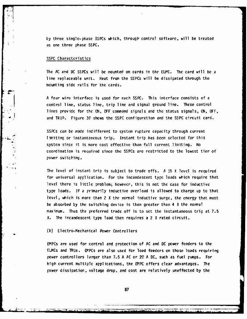
by three single-phase SSPCs which, through control softvare, will be treated
as one three phase SSPC.
SSPC Characteristics
The AC and DC SSPCs will be mounted on cards in the ELYC. The card will be a
line replaceable unit. Heat from the SSPCs will be dissipated through the
mounting side rails for the cards.
A four wire interface is used for each SSPC. This interface consists of a
control line, status line, trip line and signal ground line. These control
lines provide for the ON, OFF command signals and the status signals, ON, OFF,
and TRIP. Figure 30 shows the SSPC configuration and the SSPC circuit card.
SSPCs can be made indifferent to system rupture capacity through current
limiting or instantaneous trip. Instant trip has been selected for this
system since it is more cost effective than full current limiting. No
coordination is required since the SSPCs are restricted to the lowest tier of
power switching.
The level of instant trip is subject to trade offs. A 15 X level is required
for universal application. For the incandescent type loads which require that
level there is little problem; however, this is not the case for inductive
type loads. If a primarily inductive overload is allowed to charge up to that
level, which is more than 2 X the normal inductive surge, the energy that must
be absorbed by the switching device is then greater than 4 X the normal
maximum. Thus the preferred trade off is to set the instantaneous trip at 7.5
X. The incandescent type load then requires a 2 X rated circuit.
(b) Electro-Mechanical Power Controllers
EMPCs are used for control and protection of AC and DC power feeders to the
ELMCs and TRUs. EY.PCs are also used for load feeders on those loads requiring
power controllers larger than 7.5 A AC or 20 A DC, such as fuel pumps. For
high current multiple applications, the EYPC offers clear advantages. The
rower dissipation, voltage drop, and cost are relatively unaffected by the
87

HEAT SINK CONTACT AEA
COMPONENT
AREA
HEAT SINK CONTACT AREA
TYPICAL UNIT115 VAC/28 VDC BUS
CONTROL -- FUR IN
STATUS
TRIP/BIT LOADI- -NEUTRAL I IOA
Figure 30 SSPC Circuit Card and Configuration
as

nominal current rating, over the range of 5 to 125 amperes. EMPC costs are
primarily determined by rupture requirements.
The EMPCs will be interfaced to the data bus system through RTs. EMPCs used
as feeder controllers will employ a "FAIL ON" type interface. This is agrounding signal for a close or ON command. The interface for the EMPCs has
not been determined and requires further study.
(4) Electrical Pemote Terminal
The ERT provides the primary interface between air vehicle subsystem
equipments, SSPCs and a MIL-STD-1553B data bus. In addition, the ERT provides
"- I the interface between various DAIS core elements. Major components of an ERT
include discrete data I/O units, analog data input units, an imbedded
microprocessor, a multiplex terminal unit (FTU), an I/O decode control unit
and a power supply. Pajor ERT components and their functional relationship
are shown in Figure 31.
Control of the ERT, its I/0 subsystems, and bus interface is handled by anembedded microprocessor. This processor provides the necessary intelligence
to the EPT for processing and controlling discrete inputs, discrete outputs
and analog inputs. An ERT receives messages from the 1553B data bus and
converts the information received to a form suitable for outputs as AC or DC
analog, and discrete, synchro or serial digital signals to aircraft
subsystems. Similarly, signals received from aircraft subsystems can be
transformed by the ERT to a format suitable for inclusion in a message on the
1553B data bus. When required, an ERT can retain signal levels until they arc
changed by another bus message. Design of the ERT will be modular and
flexible to allow signal handling to be incrementally expanded or contracted
in order to satisfy the requirements of a particular geographical location.
(a) ERT Functional Description
ERT Processor
The ERT processor is a programmable general purpose microcomputer that
89
* -M

LT1 -1
Kr
SM, I
I n E f
Heel(
I ~ I ~90

provides the data interface and control function between the ITU and air
vehicle subsystems, and provides control of communications on the ER7 local
bus. Characteristics of the processor include the following:
16 bit word size
Arithmetic Operations (basic)
16 general purpose registers
Direct addressing to 64K bytes
Interrupt capability
Single supply voltage
The processor memory will contain both PROM and RAM of sufficient size to
support the functions and operations of the ERT. The PROP card will be
configured such that it can be addressed either as 64K 8 bit bytes or as 32K
16 bit words. The RAP card will be configured so that it can be addressed as
16K 8 bit bytes or as 8K 16 bit bytes. Both memory types will have an access
time sufficient to support the processor without creating "wait" states. Ablock diagram of the processor is shown in Figure 32. The single
bidirectional 16-bit data bus serves as an interface between the CPU and the
_MTU data buffers and subsystem. The ERT processor is programmed to"personalize" each ERT according to the interface module mix as determined by
subsystem requirements.
Currently, there does not exist a 16 bit microprocessor capable of executing
the M-IL-STD-1750 instruction set. It is anticipated that such a processor
will become available in the next 2 to 3 years. Meanwhile, functions of the
ERT can be implemented by using a Z8000 series microprocessor. A Jovial
compiler is expected to be available for the Z8000 in 1982. Machine dependent
code will have to be implemented in ZSOOO assembly language.
Multiplex Terminal Unit
The Fultiplex Terminal Unit (PTU) is designed to provide an interface between
the ERT and the 1553B data bus and to support the bus protocol as defined in
PIL-STD-1553B. The KTU contains a transmitter/receiver section, data bus
coupler, and control logic. The PTU must first be programed by the power
system processor via the 1553B data bus to perform the following:
91

w0
C)
dtn
0
- 0-
I- -J 4 JClC
U-= .
CA
LU d~c
a91
LI
cnJ
W LS
of
9.C-
0. (nUn
C-D
-i c-
,-& Lrl 2-
92

a) Output data
1) Location
2) Amount
b) Input data
1) Location
2) Amount
Once a remote FTU has been programmed, it monitors all bus traffic waiting for
__L. its specific address. After its address has been decoded, an MTU responds toA !the particular command being sent. An IFTU also checks incoming data for
parity, bit count, word count and protocol errors. The proper message sync,
parity bits and status information are inserted into the response word by the
MTU. Once a remote MTU has been initialized, it can execute an entire bus
fratme without processor intervention when commanded.
-- The transmitter/receiver portion of the FTU converts digital data to
.,anchester data for transmission on the bus. Manchester data is converted to
digital data when received from the bus. The data bus coupler is a
transformer coupled device that isolates the ERT from the main bus and
provides proper matching impedances between the ERT and the data bus.
I/O Decode and Control
The ERT 1/0 decode and control section performs repetitive functions that need
to be removed from processor operation. This circuitry is closely coupled
with processor activity and is used by the main controlling function for
routing data to and from digital I/O circuits.
Discrete I/O
The discrete input circuits will be capable of handling 250 inputs. These
circuits provide necessary signal conditioning and supply conditioned
digitized data to the processor under control of the I/O decode and control
section. The discrete output circuits will be capable of handling 118
outputs. These circuits provide drive and signal characteristics required by
the driven devices and receive data from the processor under control of the
I/O decode and control section.
93

Analog Inputs
The analog input circuits will be capable of receiving 32 low level
differential inputs or 64 high level single ended inputs. These circuits
contain the electronics required to perform signal conditioning, mode
selection, multiplexing and AID conversion. Data received and converted is
routed to the processor under control of the 1/0 decode and control section.
Power Supply
The power supply receives power from the aircraft power bus end converts it to
regulated voltages required by the ERT. The power supply contains circuitry
to inform the processor of a power shutdown or fault in order to allow
graceful shutdown. P power on reset will be generated by the power supply.
(b) EPT Executive Software
The purpose of the ERT executive (ERTE) is to provide an interface between
hardware comprising the electrical load management center, and the ERT
applications software that executes in the ERT processor. This interface
permits applications software development without knowledge of the information
transfer system hardware or its operation. Similarly, this allows hardware
modifications to be performed without affecting the applications software
since references to time or to hardware devices are on a logical level. The
ERTE is basically the same as a standard DAIS single processor synchronous
executive (DAIS specification SA 221308), except that it does not perform data
bus management, a function reserved for the avionics processor. The ERTE
controls operations peculiar to the processor, including control of the ERT
applications software and local participation in the I/C processes.
The architecture of the ERTE implies a separation of functional components,
control of one component over another, and dependence of one component on
another. The ELMC system architecture including the ERTE is shown in Figure
33 depicting the separation of hardware and software functions. As shown in
Figure 33, ERT applications software is functionally isolated from the
hardware by the executive software.
94

ELMC
ERT
ER lP
APLCAINSCNTO
_____SOFTWARE___ DA IT53 DT U
ELCRIA
FR3ELM ArhtetreI cluigET xctv
TERMINL (105

The ERTE is a realtime system, in which the activities of the ERT applicetions
software are coordinated with the passage of real time in the outer world.
The minimum unit of time to which coordination occurs is known as the minor
cycle. It is possible to specify or determine the time of an action within
one minor cycle, but not to a fraction of a minor cycle. Thus, I/0
interactions and task interactions may occur, may be known, and may be
controlled within the framework of the minor cycle time unit. This timing is
a requirement for I/0 control, synchronization and executive process handling.
.In order to successfully control activities of the ER7 applications software,
the ERTE performs several functions. These functions include task control,
event handling, compool block handling, executive control, minor cycle setup,
and local initialization. These functions are identical to the correspondingfunctions of the PSP executive, and are discussed in Section III.2.c.(1).(c),
PSP Executive Software.
(c) ERT Applications Software
The main purpose of the ERT applications software is to control and monitor
electrical power that is distributed to individual aircraft loads via SSPCs.
This must be done in a manner consistent with the current load management
priority level as determined by the PSP. The ERT applications software
resides in the ERTs and executes under control of the ERTE. This software is
table driven, and those tables that are unique to individual ERTs are loaded
from the DAIS mass memory unit at system initialization time. This provision
allows identical program code to be used in all ERTs. To accomplish its
purpose, the ERT applications software must perform several different
functions. Functions to be performed include the following:
ERT startup
ERT shutdown
Power bus control and status monitoring
Load priorities handling
SSPC control equation solving
SSPC status equation solving
96

Aircraft sensor discretes monitoring
1553B data bus message handling
These functions are described below.
ERT Startup
ERT startup occurs when the ERT executive receives an initialization request
from the FSP applications software. When this happens, the aircraft
electrical control system is initialized as follows. Load management tables
are down loaded from the PSP via the DAIS 1553B data bus. An ERT ready status
is sent to the PSP.
ERT Shutdown
ERT shutdown occurs when the ERT executive receives a shutdown request from
the PSP applications software. When this occurs, all outstanding powerrequests are completed, and a completion message is sent to the PSP. No
additional power requests or load management level changes will be accepteduntil the ERT receives an initialization request.
Power Bus Control and Status Vonitoring
The power distribution controller, shown in Figure 29 provides automatic
selection of power sources for the ELMC AC and DC buses. Whenever automaticpower source selection occurs, a status flag bit is altered so that this
software module can detect current status. This status is then sent to thePSP via a DAIS 1553B bus message.
The PSP applications software uses ELMC feeder selection status when analyzing
power distribution network configuration. If a power distribution networkreconfiguration occurs, and if this results in required changes to EIYC feeder
selection, a DAIS 1553B data bus message is sent to the appropriate ERTs.
This message is interpreted by the power bus control and monitoring software
which then overrides the automatic power feeder selection and causes a changein ELMC power sources to occur. A message giving updated feeder selectionstatus is returned to the PSP applications software.
97
L _.J ... . ... .• . - - " ... .... -'A

Load Priorities Handling
Load priorities handling occurs whenever a message is received from the PSP
applications software, indicating that a new electrical load management
priority level is in effect. This software module saves the new priority
level and then calls the SSPC control software module to RESET any SSPCs that
are currently set, but are not allowed to be SET under the new load priority
level.
SSPC Control Equation Solving
SSPC control equations must be solved whenever a request for power message is
* ;received from the PSP, or whenever a new load management priority level isimplemented. For each ERT there are a maximum of 100 SSPC control equations
of the form:
C =1P (R + Q)
Where P is a single variable, L is the solution to the latch equation, Q is atest request, and R is a request bit obtained from the PSP applications
software.
SSPC Status Equation Solving
Power system status equations arc solved whenever status changes occur with
the SSPCs, or when requested by the PSP applications software. Each ERT has
100 power system status equations of the form:
I = (L + PX)
where L is defined as in power system control equations above; P, and X are
single variables available to the system designer for definition.
Aircraft Sensor Discretes Yonitoring
Aircraft sensor discretes are collected and sent to the PSP.
98

,4... I I . . . .
1553B Data Bus Fessage Handling
The 1553B data bus message handling software module periodically checks the
message input buffer and reads any messages that have been placed there.
Each message is decoded to determine its function, and the appropriate
software module is called to process it. The data bus message handling
module is also called by other software modules to format output messages for
transmissions on the 1553B data bus. Bus messages received and the
corresponding actions taken are listed below.
ERT startup
call ERT startup moduleERT shutdown
call ERT shutdown module
Power bus feeder select
call power bus control and status monitoring module
Power request matrix
call SSPC control equation solving module
Load management priority level
call load priorities handling module
(5) Remote Terminal
Standard DAIS RTs will be used where the intelligence provided by ERTs is not
needed. As such, RTs will be used to provide interfaces between air vehicle
subsystem equipments and the IvJL-STD-1553B data bus. Also, RTs will provide
an interface between the power distribution system and the 1553B data bus.
The RTs will conform to the DAIS standard design as defined in DAIS
specification SA 321 301 (Reference 12). Pajor RT components include
multiplex terminal units (PTU), timing and control unit (TCU), and interface
modules (IF).
Fultirlex Terminal Unit
The FTU forms the communication path between the TCU and the 15538 data bus.
The PTU receives control and information signals from the TCU and, based upon
99
* - --- -- -- - - ------.-...------.----- ,--.- ~

these signals, performs transmit operations on the 1553B data bus.Conversely, the PTU accepts data bus words and generates control and
information signals tu the TCU for the purpose of passing received data bus
words to the lCU.
Timing and Control Unit
The TCU consists of microprogrammable standard functional modules. A single
f' bi-directional 16-bit data bus serves to interface the CPU and sequencer logic
to FTU data buffers and the IM control and data buffers. The micro~rc-ram
exercises the proper data paths to perform TCU functions of bus monitor,
command decode, receive, mode command operations, transmit, status word
transmit and built in test.
o Bus Monitor
The RT monitors both VTUs for a connand detect. When a conand is detected,it is decoded and the terminal address is determined. If the terminal address
belongs to the TCU, the command word is decoded. Otherwise, the TCU returns
to bus monitoring.
o Command Decode
When a valid command is received, the TCU decodes the command and then
performs receive, transmit, or a mode command operation depending on thecontents of the command word.
o Receive Operation
The TCU receives messages from the data bus and transfers the message contents
to an appropriate IF data buffer. Data messages are validated for correct
parity and word count. If a message error occurs, the data buffer is not sent
to the IMs and a status word is not transmitted. If the message transmissionis correct, the data buffer is transferred to the IM and a status word is
transmitted.
100

o lode Command Operation
The TCU responds to all mode commands.
o Transmit Operation
Whenever required, the TCU transfers a status word to the PTU for
transmission. The TCU monitors the validity of the transmitted data by
monitoring the ITU receiver for invalid data and data parity errors. If such
an error occurs, the TCU completes the current transmission and sets the
appropriate error bits in the built in test word.
o Status Word Transmission
The TCU builds the status word and then commands the fVTU to transmit it over
*. the bus.
o Built In Test Word
The FIT word is maintained by the remote terminal TCU. The BIT wmrd contains
a message error field and a terminal failure field. The BIT word is shown in
Figure 34.
Interface Podules
Input interface modules provide signal conditioning functions that make
signals externally connected to the RT compatible with the signal interface
structure defined to exist between the TCU and interface modules within the
PT. Input interface modules perform the first subset of that complete set of
functions necessary to convert various external signal formats into the serial-
- digital Panchester-encoded waveforms required for transmission of information
over the data bus. Output interface mcdules perform the last subset of that
complete set of functions necessary to convert the serial-digital Manchester-
encoded waveform taken from the bus into the various signal formats required
by subsystems connected externally to the remote terminal.
101

MSB BIT LSB
1 2 3 4 5 6 7 8 9 1 1 1 3 1 5 1
LU
LUj
t4~ -c M.jLOC 0
LU " 0 LLL IL I. I I L L
Ln CA Lfl A c
LU -LU- LU- U LUL
IL. U- U. U w
LUw w w~ 0 CD
Figure 34 BIT Word Format and Failure Codes
102
- -- - - - - - -

o Interface 1odule lypes
Different types of IMs exist to fulfill various requirements as follows:
(1) to interface a combination of existing air vehicle subsystems with their
varied signal interface formats; (2) to interface other DAIS core elements
with their standard digital interface; and (3) to allow the transition from
present air vehicle subsystem intcrfaces to the new standard digital interface
to which future air vehicle subsystems will be designed. This transition is
to occur by the substitution of IWs and system reprogramming.
o Signal Fix Configuration* *1
Different remote terminals interface with different numbers and mixes of
signals dictated by peculiarities of the equipment locations where they are
utilized. Configuration of an PT to interface a particular signal mix is
* accomplished by mounting the proper number and type of interface modules to
|. :the remote terminal housing and by appropriate system programming of the TCU.
(6) CCU/Data Fus Interface
The CCUs are connected directly to the data bus. Information on the generator
system status and remote commands to the (CU are transmitted over the bus.
The status information is used by the power system processor to solve system
and load management equations. A data flow diagram for the GCU is shown in
Figure 35.
(7) AGCU/Data Bus Interface
The AGCU provides control and protection for the APU generator and control of
the auxiliary power contactor. The ACCU interfaces the data bus through a
power system RT. Only the auxiliary power contactor position and APU
generator load condition data is transmitted on the data bus. No control data
is transmitted to the AGCU over the data bus. AfCU control signals arc
hardwired. The AOCU can operate independently of the data bus. A data flow
diagram for the ACCU is shown in Figure 36.
103
* -- ,*

Q~~~I CDc C.L 6
gneLJ V) I-iU)i
w. C.) CDD
0A L aC -4-i DC I 40-. - . IjJJ to n >
8.4 4 6. CD 4 b4 C 40 O LuU. 04-b
0 . 0 . a a s d o -- I -
~41
Co4 9- WG
(A I-- Al I-- 4= c) 40 w co c
C.) &a-
C)
d=.4o
wi
8i L
a:-UA un i .
Ci 0 0 &J
o a J Q ~w -. ,-AJ
I& L)EU U. w~
104

LLA
ee 0 -1 LA U.
WW La j 40 u1WLa a .-O I
WL ) 00Zn
03. W " 0~-Z M
39
0
A--
- '0C
co to
-I-
.j.
0- A. -
W 0. I-
105b
(8) EPU/Data Bus Interface
The EPCU will control the external power contactor. The EPCU will also
monitor the quality of the external rower and will trip or inhibit the closure
of the external power contactor if the limits of power quality are exceeded.
The EPCU interfaces the data bus through a power system RT. External power
contactor position and a "power ready" are transmitted to the PSP from the
EPCU. The power system processor can send the EPCU an external power
contactor trip signal over the bus. The external power ON/OFF switch is
hardwired to the EPKU. A data flow diagram for the EPCU is shown in Figure 37.
3. Reliability, FPintainability, and Safety
The PSP and the ELMCs provide the capability for load management and automatic
bus switching whlich is necessary to achieve a high mission completion success
probability. The AAES architecture provides dual redundant electrical power
and distribution for mission essential subsystems. In addition, three DC
power sources are provided for the flight control system. For additionalj, backup to provide, the minimumflight control capability, battery power is
provided. The dual tvIL-STD-1553B data bus with its inherent high reliability
provides a redundant link between the control logic, the electrical loads, andthe rower generation and distribution system. As the design progresses togreater levels of detail, reliability and safety analyses will be performed to
assure that no single failure points exist that can cause loss of mission orloss of aircraft. Also, quantitative predictions will be made to determine
compliance to the FtIL-F-9490B flight controls mission completion success
probability and aircraft safety requirements.
The PSP and other avionics computers on the MIL-ST-1553B data bus provideexceptional capability for condition monitoring, fault detection, isolation
and repair verification of the AAES. This coupled with accessibilityconsiderations during the detail packaging design will assure a high degree of
maintainability.
106
-- - - - ~ - - - - ~~**~~-' - --- - - .- - .- " .. ,, -- ... . .. . .- - .

LUJI--
LUL
LLUU Ic S-4
3c I- F4 - 3a
-1 4 0 L O 0 LO)
1- L LL=U L V) - L
Cl Co CIx c CL -v c
u'U
L) 9_. IT LC
ui LJ A I-- L
CC-
LU e
L.
LJJ
LU I-.
CL 0-w I--
107

SECTION IV
LABORATORY SIMULATOR PRELIMINARY DESIGN
The laboratory simulator uses existing DAIS components to simulate an
integrated avionics and power control information system. The purpose of the
simulator is to verify the feasibility of an integrated DAIS architecture
supporting both power and avionics management functions on a single DAIS 15536
multiplexed data bus for a variety of aircraft mission equipment load
complements. The laboratory simulator provides different levels of bus
loading so that it can monitor performance characteristics for different
combinations of bus loading and PSP equation processing response times. In
addition, the simulator simulates several different operational modes for the
integrated power and avionics information system including startup, load
- management level change, electrical power generation system configuration
change, and fault isolation.
1. Configuration
A block diagram showing the proposed laboratory simulator configuration is
presented in Figure 38.
2. Hardware
The laboratory simulator includes the following hardware elements:
Bus Fonitor
System Test Console
Generator Drive Stands
Load Banks
Generator Control Unit (GCU)
Electrical Load Vanagement Center (ELM'C)
ANI/AYK-15A Computer
Console with CRT
Avionics Simulator and Bus Controller
Remote Terminal
Actual Avionics Loads
108
- ' - -- - "" - -- - - -: .. - --- 9- i -.
- - - ... . . ... -.... ..- .. " - --... . . . . . . .

LLI LAJNcoD
tn CUj
W CD CD
cc I-
0
In 4c- 0
Ln cx le4J=0
CK-LLw
AJ 9-4
i C6
C-
109

Requirements associated with each of the simulator elements are described
below.
a. Bus Ponitor
The bus monitor receives records of all bus messages and stores these messages
for possible later analysis.
b. System Test Console
The system tcst console allows the simulator operator to perform a variety of
functions in order to test and verify the integrated avionics and electrical
control information system. Among capabilities provided arc the ability to
cause open and short circuit conditions in the electrical power distribution
system and in the SSPCs. The system test console also provides display of
power system status messages, display of all overload trip data, and display
of addresses of all failed terminals. In addition, the system test console
allows an operator to generate override commands for inhibiting automatic load
management configuration, electrical system startup and shutdown messages, and
to generate system stress tests by changing bus loading and bus response times.
c. Generator Stand
The generator stand provides the capability to test tvo generators on line
simul taneously.
d. Load Bank
The load bank provides the capability to load the system SSPCs. All loads
interface to ELK C SSPCs or to AC distribution buses directly via electro-
mechanical power controllers.
e. Generator Control Unit
The GCU contains a remote terminal that provides the interface between the
DAIS 1553B data bus and the electrical power generator. The GCU also provides
110
- W -.. . ,,,-"1 1 I . ... . . .,. .. .

the interface with the 15538 bus for the main AC bus control and status data.
For the laboratory simulator, it may not be necessary to develop special GCUs
with RTs. Instead, existing GCUs could be modified to interface to DAIS RTs.
f. Electrical Load Management Center
The ELMC performs several different functions as part of the laboratory
simulator. These functions include control and monitoring of SSPCs and
collecting SSPC TRIP status. In addition, the ELMC receives power requests
from the 1553B data bus and controls and monitors AC and DC power bus
interfaces to the SSPCs.
g. AN/AYK-15A Computer
The AN/AYK-15A computer, containing 128K 16 bit words of memory performs powersystem management functions in the laboratory simulator.
h. Console with CRT
The laboratory simulator console and CRT provide an operator interface to the
power system processor executive software for activation and suspension oftasks. The console and CRT also provide for operator examination of power
system processor memory contents.
i. Avionics Simulator and Bus Controller
The avionics simulator and bus controller performs several different functions
as part of the laboratory simulator. Functions performed by the avionics
simulator and bus controller include control of all 15538 data bus traffic,
generation of bus messages containing errors for failure simulation, and
simulation of avionics bus loading traffic. The avionics simulator and bus
controller also provide the interface between the PSP and the system testconsole and determine when failure by hardware devices attached to the 1553B
data bus occurs.
111

j. Remote Terminal
The laboratory simulator remote terminal inputs and outputs discrete and
analog data from test sensors.
3. Software
The laboratory simulator requires software to be developed for the bus
controller and the avionics simulator only. The power system processor and
any ERTs that are used in the laboratory simulator will use software that isdeveloped for use on the aircraft . The bus monitor software will perform
functions necessary to monitor and analyze messages that are transmitted onthe DAIS 1553B data bus. This software will provide snapshots and errortrapping of bus messages in order to facilitate debugging, testing, and
verification of electrical control system hardware and software components.
.7 The avionics simulator software will provide those functions of the avionicsprocessor that are essential for successful operation and testing of the
advanced aircraft electrical control system. These functions include control
of the DAIS 15536 multiplex data bus, simulation of avionics controls data and
functions to the electrical control system, loading of the data bus to
simulate avionics bus traffic, and processing of avionics display data.
112
SECTION V
WORK EFFORTS FOR DETAILED DESIGN
In this section work efforts required to complete the detailed design
scheduled for Phase II of this program are described.
1. Avionics Processor
The avionics processor is a DAIS AN/AYK-15A computer. Existing avionics
executive and application software is used. Software modifications will beminimal. These modifications are required for data transfer between the
avionics processor and the power system processor. Modifications are also
required to accommodate the controls and displays requirements of the
electrical system since the avionics processor controls the existing DAIS
control terminal s.
The followring work efforts are required for the avionics processor:
o Identify data transfer requirements between the avionics system and
electrical control system
o Develop software requirements for electrical control system use of
DAIS controls and displays
2. Power System Processor
The power system processor (PSP) is a DAIS AN/AYK-15A computer. The DAIS
executive software will be modified for the PSP. The PSP application software
is new and a specification for this software will be developed. The PSP
application software covers almost all facets of the electrical system
operation and thus requires several areas of detailed developnent. These
areas are listed below:
113
f

o Load management operation
o Define inputs to load management algorithm
o Define power request equations
o Define priority management operation
o Develop built-in-test procedure and requirements for the electrical
system
PSP Executive Software
A standard DAIS single processor synchronous executive, specification #SA
221308 must be modified so that it provides an interface to the 1553B databus, but does not perform bus control functions.
3. ELIPC
The ELMC is a new item. Both hardware and software must be developed.
Hardware development focuses on two areas, the SSPCs and the ERT. The
software development also focuses on two areas, the ERT executive and the ERT
application software.
a. ELY-C Hardware
(1) SSPCs
The SSPCs will be packaged on printed circuit cards. Input/output connections
to the SSPCs will be made through edge connectors. The work efforts to
accomplish this design are:
o Determine thermal requirement
o Determine card size
o Standardize on nunber of SSPCs per card based on current rating
o Determine SSPC control interface based on wiring and circuitry
constraints
114
- ,----- -=r : ii .-: : _ - ..... . ... - - -., ..

(2) ERT
The ERT hardware development is straightforward. The data developed duringthe preliminary design must be translated into detailed requirements
specifications. An analysis of the impact on packaging and interfacing 100
SSPCs with a 4-wire system and a 2-wire system will be made. Based on thisanalysis a dccision on the interface will be made.
b. ERT Software
(1) ERT Executive Softare
"* I The ERT executive software must be developed. This executivc will be
patterned after the DAIS single processor synchronous executive, as in
specification SA 221308. This executive must be modified so that it does not
4 perform bus control functions.
(2) ERT Application Software
The ERT application software covers the control and monitoring of the SSPCs,control and monitoring of the power distribution center, and processing of
general I/O to be defined. The follow.ing work efforts will be required:
o Define aircraft load complement
o Define ELMC discrete I/O and analog inputs
o Define load control equations
o Define procedures for load management priority level changes
4. Remote Terminals
DAIS RTs are used in the system. The I/0 requirements for the RTs must bedefined so that the proper interface modules can be specified for the RTs and
any new design requirements for the interface modules can be identified and
designed.
115
'1'. . ..- - -A, , ;. . . : ... , . I

5. GCU
The CCUs for the PAES are presently designed with a built-in data bus
interface. This represents a new design for CCUs. A detailed design will be
performed for the GCU in Phase II. To accomplish the design, the following
efforts will be required:
o Identify generators to be used in the simulator
"~ o Define time delays required for the GCU protective functions
o Define GCU discrete and analog I/O
6. Controls and Displays
Existing DAIS controls and displays unit will be used by the system. In
addition, a control panel for the electrical system will be developed. This
"'.--. panel will supplement the DAIS unit. In Phase II the following efforts will
,' be required:
o Identify data to be displayed on DAIS C & D
- . o Identify functions for the control panel
116 .

SECTION VI
CONCLUSIONS AND RECO44ENDATIONS
1. Results and Conclusions
Task 3 of Phase I of the Advanced Aircraft Electrical System Control
Technology Demonstrator Program consisted of preparing a prel iminary design of
the electrical power system with an integrated electrical/avionics data bus
architecture. Drafts were prepared of Part I specifications of the overallsystem and the major component hardware and software. The preliminaryperformance requirements for the Power System Processor, Electrical Load
t'anagement Center, and Electrical Remote Terminals were defined. The software
for the PSP and ERT are divided into the Executive and Applications Software.Both the PSP and ERT will use the DAIS Single Processor Synchronous Executive
(DAIS Part I Specification SA 221308) with minor modifications and will not
include the bus control functions. In the integrated architecture design the
bus control function will reside in the Avionics Processor.
Outlines of the Part I specifications of the System Test Console and the
Advanced Electrical Power System (AEPS) Simulator have also been prepared.
All draft specifications are included in a separate document, as is a draft
outline of the Initial Demonstration Plan.
Preliminary design of the ELMC indicates there may be problems with packaging
100 SSPCs in the ELC. The area of concern is the amount of wiring required
to interface the SSPCs to the ERT and the loads. Further examination is
planned in this area. The results may be a change in the SSPC interface
method or a decrease in the number of SSPCs per ELMC. If the latter
determination is made, further study of the impact of this change on the data
bus loading and PSP processing will be required. Also during the design of
the ERT it was discovered that a 16 bit microprocessor capable of executing
the FIL-STD-1750 instruction set was not available. A Jovial compiler is not
available for the Z8002 microprocessor presently selected for the ERT.
117
. . . . . . . . . . - .. . . . . . ... .

Preliminary design studies for the laboratory simulator indicate that the busmonitor and the avionics simulator/bus controller functions can be performed
by off-the-shelf hardware boxes at a cost of approximately $20K each. Two
such boxes would be needed. It will be necessary to build the ELMC/ERT, and
to provide a power system processor, DAIS RT, and a generator control unit in
addition to a load bank and operator console in order to successfully
implement the laboratory simulator.
A preliminary hazard analysis (PHA) of the system was conducted and is
documented separately. This PHA indicates that none of the major component
failures will be of a catastrophic or critical category, and thus the program
can move from the preliminary to detailed design phase without major
reorientation.
All aspects of the design indicate that the basic integrated architecture for
avionics/power system control is feasible and should continue into the next
phase. The design philosophy selected segregates the avionics data bus
traffic and power system data bus traffic by utilizing separate avionics and
power system processors and allows considerable flexibility by minimizing, if
not eliminating, the impact of changes in one from the other. An added
benefit of this design philosophy is the capability of transitioning the
design from an integrated to a hierarchical data bus architecture. For this
transition the PSP would need to be enhanced to include the bus controller
functions and interbus processing functions. The interbus processing
capability for the PSP is not planned to be develored in this program, however.
2. Recommendatiens
Since the preliminary design of the integrated avionics/electrical power
system control architecture does indicate that such a system is feasible, it
is recommended that the program be allowed to proceed into the detailed design
phase. Specific activities to be conducted in the tasks for the aircraft
electrical system design and the design of support hardware and software are
defined in the Design and Development.Plan for Phase II which is documented
separately.
I18
- - - -- -~-----J-.-

Consideration should be given to expanding the score of Phase 11 by the
addition of a third task to develop the hardware modifications and software
necessary for the Interbus Processor. This additional task will enhance the
capability of the design to be rapidly reconfigured from an integrated bus to
a hierarchical bus architecture and make the system compatible with aircraft
which require separate data buses for avionics and electrical system controls.
S119

REFEPENCES
1. AFAPL-TR-73-41, Pultiplexing in Aircraft Subsystems; SCI Systems, Inc.,Huntsville, Alabama, July 1973.
2. AFAPL-TR-72-88, Further Evaluation of the Solid State Simulator for theA-7B Aircraft Electrical System, G. Kevern, April 1973.
3. AFAPL-TR-78-93, RPV Electric Power System Study, Phase II: Hot BenchPockup Development, Teledyne Ryan Aeronautical, November 1978.
- 4. AFWAL-TR-81-2058, Advanced Aircraft Electrical System Control TechnologyDemonstrator - Phase I: Requirements Analysis and Conceptual Design,Boeing Pilitary Airplane Company, July 1,81.
5. AFAPL-TR-79-2084, Power System Control Study, Phase I - Integrated* iControl Techniques; Vought Corporation, Cctober 1979.
6. AFAPL-TR-78-55, Advanced Solid State Power Controller Development, PhaseI - Study Report, Telephonics Corp., September 1978.
. 7. SA120100, SCN #1, System Specification for the Digital Pvionics
Information System, 11 Jan 1980.
8. L409C2008 B-1 EV-UX Specification, Rockwell International, B-1 Division.
9. SA-421205 Time Item Development Specification for AN/AYK-15A DigitalProcesor, Part 1, Type B-i, DAIS Library, 1 Apr 1979.
10. PA 221200 System Control Procedures, AN/AYK-15A, June 1980.
11. SA 221308 Computer Program Design Specification for the Single ProcessorSynchronous Executive, Part 1.
12. SA 321301 Prime Item Development Specification for DAIS Remote Terminals,Type Bi, Pay 1979.
120