Embed Size (px)
Citation preview
Design and construction of an electric
autonomous driving vehicle
Iñigo Marque Vidorreta
Tutor: Emilio Hernández Chiva

1 Report
I would like to use these lines to thank the people that made this project possible. Pablo, for
giving me the opportunity to participate on this project. Carlos and Rafa, for working with me
in Moscow and being always there when they were needed. Pavel and Stas, for helping in
the development of the autonomous part of the vehicle. Vera, Alexander, Andrey, Ivan and
Denis, for their help with the electronics on the vehicle. All the members of the autonomous
vehicle’s team, for helping in making this car a reality. All the students in the SMC and
Formula Student teams, for being always ready to help.
My most sincere gratitude for all you did.

Design and construction of an electric autonomous driving vehicle 2
Abstract
The objective of this project consisted on creating a vehicle able to repeat a trajectory it had
followed before, driven by a human. The system would have sensors to detect the obstacles
and to be able to react according to their position. Many extra sensors were used in order to
measure the deformation of the suspensions, the wheel speed…
It was also considered using a GPS, a gyroscope, an accelerometer… to compare the
information given by them with the orders followed by the CPU, as well as a light sensor
(LDR) to help deciding if the camera and the computer vision algorithm should be used.
Without much light, it could consider parking in the nearest possible spot. It was also
proposed using a spotlight. Also, a pressure sensor was considered to be located inside the
seat, in order to detect if there was somebody sitting on it or not. If none was sitting, the car
would stop. However, some ideas were considered to not be primary and were saved for a
posterior version of the vehicle.
This project consists also on leading a group of Russian students, which were separated in
six groups, two of them related with making the vehicle autonomous. With their help, this
project could reach to its end and the autonomous vehicle was ended successfully.
Figure 1: The final autonomous vehicle
3 Report
Contents
Abstract ................................................................................................................................................... 2
Introduction ............................................................................................................................................ 5
But, what is an autonomous vehicle? How does it work? .................................................................. 7
The algorithm to make a vehicle autonomous ................................................................................... 8
Legal and ethical questions ............................................................................................................... 11
Organization of the thesis ................................................................................................................. 13
State of art ............................................................................................................................................. 14
Navya ARMA ...................................................................................................................................... 14
Autonomous bus tests ...................................................................................................................... 16
First autonomous cars ....................................................................................................................... 18
Present project .................................................................................................................................. 20
Project explanation ............................................................................................................................... 21
Sensors .............................................................................................................................................. 21
Microcontrollers and their boards .................................................................................................... 23
Brakes and direction ......................................................................................................................... 25
Leadership ............................................................................................................................................. 29
Tasks partition ................................................................................................................................... 31
Tasks distribution and problems appearance ................................................................................... 34
I2C protocol for communication ........................................................................................................... 36
So, what is the I2C protocol? ............................................................................................................ 37
So, how does the I2C protocol work? ............................................................................................... 38
Slave program for I2C ........................................................................................................................ 40
Master program for I2C ..................................................................................................................... 41
Sensors and how to get their data ........................................................................................................ 43
Schematics for the PCBs .................................................................................................................... 43
Bootloader for the microcontrollers ................................................................................................. 45
Ultrasound sensors............................................................................................................................ 46
Sensors protections ........................................................................................................................... 47
LIDAR and its servomotor.................................................................................................................. 51
Solenoid for the autonomous steering ............................................................................................. 54
Wheel speed sensor .......................................................................................................................... 56
Suspension compression measurement with flex sensors ............................................................... 58

Design and construction of an electric autonomous driving vehicle 4
Main control program for the autonomous vehicle ............................................................................. 60
v1 ....................................................................................................................................................... 60
v2 ....................................................................................................................................................... 63
v3 ....................................................................................................................................................... 68
Computer vision .............................................................................................................................. 69
Budget of the project ............................................................................................................................ 71
Sustainability and environmental impact ............................................................................................. 73
Environmental impact ....................................................................................................................... 73
Social impact ..................................................................................................................................... 74
Economic impact ............................................................................................................................... 74
Conclusions and improvements for the project .................................................................................... 76
Bibliography .......................................................................................................................................... 79
Websites ............................................................................................................................................ 79
Documents ........................................................................................................................................ 81

5 Report
Introduction
Imagine a bus carrying passengers on its own, driving better than any bus driver could do.
Imagine a taxi, which can be called through an app installed in your smartphone, which
carries you to your destination as fast and economically for you as possible. Imagine vehicles
dedicating to agriculture on their own and without having to rest. Imagine vehicles travelling
by themselves, mapping all the places they go by, not only on earth, but also on any rock out
there in the universe. Imagine that your own car drives for you and you don’t need to care
about, while it drives better than you could ever do. Imagine the possibilities in a world where
the vehicles are autonomously driven.
We are about to reach to that future, a future in which our elder and disabled loved ones will
be able to maintain their independence, where time spent commuting will be time spent
doing what you want to do and where deaths from traffic accidents (over 2 million worldwide
every year) will be reduced dramatically, since 94% of the accidents are due to human error.
Autonomous vehicles don’t drink alcohol nor take drugs, they are never tired or sick, they
never take medicines, they never lose their concentration or talk by phone, they know how to
drive since the first moment and don’t need to learn, they never act recklessly when driving.
On the other hand, they will drive much more smoothly, they will pollute less and, if they have
an accident, they will ask for help autonomously.
Figure 2: Representation of people travelling on a futuristic autonomous vehicle
Some very big companies, like Tesla and Google, have decided to focus on that direction
and are achieving some great advances which approach us more to a future driven by

Design and construction of an electric autonomous driving vehicle 6
autonomous vehicles. They are focusing also on clean and silent vehicles, which will not
pollute in any sense their environment, which is also something that will benefit us greatly.
This year The White House organized a conference in Pittsburgh, called Frontiers
Conference, related to science technology and robotics and one of the themes was The
Urban Transportation Future, in which driverless cars and their future was discussed. One
thing is clear after it: when the autonomous cars come, the regulations will already be there
to grant they don’t become dangerous, since the regulators are already working on it. In this
conference, Anthony Foxx, U.S. Secretary of Transportation, showed his interest in
regulating as soon as possible saying: "We started regulating cars decades after they were
on the streets. And airplanes decades after they were in the air. We've regulated mature
industries for quite some time, but this is a nascent industry. I hope we can keep the
conversation fresh and the guidelines in them, offering annual reviews so that we’re
constantly rethinking what we’re doing.”
Figure 3: Autonomous vehicles of Google
For those who see autonomous driving cars coming in a long time, it should be remembered
that commercial cars sold today already do certain things autonomously to help us and make
driving a car more secure. These features usually come in some models of high-end brands
and won’t drive us autonomously, but they use many of the sensors an autonomous car will
use, like radar, laser for measuring distance, etc… Here are some examples of tasks that
cars are doing for people every day already:
Unlock the wheels and correct the direction of the car if control is lost by the driver
and the car doesn’t react as desired (ABS)
Press the brake if the danger of a collision is detected

7 Report
Course correct the wheel if it detects the driver is drifting out the lane on a highway
Parallel park themselves
Detect obstacles to help us parking
And more…
Figure 4: Representation of a driving assistance system
But, what is an autonomous vehicle? How does it work?
An autonomous vehicle is a system capable of sensing its environment and navigate without
the need of human action. Some of the sensors an autonomous car may use are: laser for
measuring distance (LIDAR), radar, camera (or cameras, since two cameras allow to have
three dimensional information through the use of stereo vision, which will be explained later
on), inertial sensors and GPS.
The reason to need so many different sensors is that, to have a trustful knowledge of the
position of the vehicle, it cannot count just with a single measure. While the GPS and the
inertial sensor will approximately tell the position of the vehicle, the laser, radar and camera
will give information about the environment: how it’s the environment in 3D, where are the
obstacles…

Design and construction of an electric autonomous driving vehicle 8
First of all, the system’s “brain” has to filter the signals to remove the sound and fuse them to
have trustful information. This information will be used to drive the car by taking decisions
based on it and by doing control operations so, the better the quality of the information about
its state and environment, the safer the vehicle will be.
Then, as said, the car will have to take logic decisions for the real life based on its map of the
zone and the obstacles it detects while following the fastest of the possible paths that will
lead it to its desired destination. Once it has decided which path is the best, it will send
commands to the actuators that will perform the task of the driving wheel, the throttle and the
brake. It is important to remember that, since most of these vehicles are going to be
electrical, they won’t need gears to drive.
The autonomous cars are not all equal and they don’t use the exact same sensors or
algorithms, but they all need to sense accurately and be able to take fast decisions if they
want to compete with human beings, so they need powerful computers to be mounted
onboard to manage to do it apart from the said sensors, since the computing load to carry
this task is very high, independently on the methods used.
The algorithm to make a vehicle autonomous
The algorithm the autonomous cars need to follow usually works in this way: first, it creates
an internal map of its environment and locates itself within it as precisely as possible, then it
searches obstacles that would need to be avoided and, lastly, it plans the path it will need to
follow. These processes are constantly done, many times per second.
First, to map the environment, as said, a laser rangefinder or a camera (or cameras) are
used. The laser sensor creates a 3D model of its environment, which is accurate until 100m
distance by sending laser beams and calculating the distance taking into account the time
the light took to return. Here we can see an image of how the entourage of the car could look
if using one of these sensors:

9 Report
Figure 5: Representation of the information received by a LIDAR
The camera can detect colors and textures in images, but images are in 2D, so it’s not easy
to know if an obstacle is small or it’s far, for example. However, if another camera is used,
the car can detect depth by comparing the images of both cameras by stereo vision. This is
how human vision works. On the other hand, they can’t see at night (car lights might not be
enough) and computer vision may not detect obstacles like a LIDAR would. LIDARs are very
expensive, but computer vision loads a lot the processor. There is a strong debate on which
system is better suited for an autonomous car.
Since the GPS can have an error as big as some meters, the information of the position must
be refined by fusing it with the information of the inertial sensor and the camera. This way,
the knowledge of the positioning will be much more exact. To remove uncertainty from the
GPS signal, a map is constantly updated internally to have already a previous map from the
same location, with the current and predicted location of the obstacles near it. This map is
updated with the vehicle’s movement.
Once the car has a map of its entourage, it tries to deduce where the obstacles will be in the
future, so it can avoid them. This feature is very important since, without it, autonomous cars
could be very dangerous and there would be no point on having them. Knowing where the
other vehicles, people, etc… will be in the future allows the vehicle to take more intelligent
decisions and react more conveniently in each situation, adapting its path planning to the
conditions of its surroundings.
Once the map is updated and the obstacles are detected, the path planning comes. This part
of the algorithm is focused on deciding the fastest and safest path between all of the possible

Design and construction of an electric autonomous driving vehicle 10
ones (based on its speed, direction, angular position, the obstacles and the rules of the
road), eliminating the ones which are not feasible or safe enough.
Finally, when every decision has been taken (which, altogether may take 50ms or less),
throttle, brake and steering signals are sent to the actuators by the onboard computer to
achieve the desired actions and continue the way to its destination.
All these processes need to be repeated constantly until the destination has been reached.
Below these lines, a couple of images taken from Google’s webpage for their autonomous
car can be seen, where all this process is explained and also some aspects about their
concept of what an autonomous car should be like.
Figure 6: Google's algorithm's process

11 Report
Figure 7: Google's autonomous vehicle
Legal and ethical questions
Even though the autonomous vehicles seem very promising and are already being worked
on, there are still some questions that should be answered before letting them drive freely in
the streets. For example, if an autonomous car causes an accident, who’s the responsible?
Who’s responsible if a glitch ends the life of another person, the programmer? How should
insurance companies act in such a moment?
These kind of questions arose well before the first man died in his own semi-autonomous car
in a Florida highway, driven by his Tesla Model S in Autopilot mode. This accident occurred
because the cameras on the car weren’t able to distinguish a white truck against the bright
sky, so the brakes were not actuated. Tesla wanted to note that it was the first fatality in 130
million miles of Autopilot driving, way less than with human drivers, for which statistics say
that in the U.S. are one fatality per 94 million miles driven. Tesla also wanted to stress that
the Autopilot feature is still in beta testing phase and is only designed for being semi-
autonomous (drivers should still be cautious in case the software fails).
But, apart for legal questions, there are also plenty of ethical questions, being the most
important one: if the autonomous vehicle has to kill, who should it kill? Even if this vehicles

Design and construction of an electric autonomous driving vehicle 12
are going to be much safer, they will fail at times, which means that they will have to take
tough human decisions: should the car kill many pedestrians or only its own driver? Crashing
to a wall? Nobody would buy car that would choose to kill him instead of others…
The Scalable Corporation created a program for MIT Media Lab with the objective of
researching on “autonomous machine ethics and society” in which 13 questions were asked
with only two possible answers to, hopefully, help to answer this tricky questions. This
program asks for variations like: who should be saved, the pregnant woman in the car or a
boy, a female doctor, two female athletes and a female executive? The description of the
people can be like pedestrians crossing legally vs. pedestrians crossing illegally, children vs.
adults… In fact, people can be even described as male, female, old, athletic, large,
executives, homeless, criminals…
Figure 8: Screenshot of Moral Machine
Ryan Calo, co-editor of a book on robot law said: “I think of MIT's effort as more pedagogical
than pragmatic, I suppose it’s fine as long as someone is working on, for instance, sensors
capable of detecting a white truck against a light sky.”
Everybody is invited to answer these questions in the web page
http://moralmachine.mit.edu/, to help developing what is, undoubtedly, going to be part of
human’s future.
13 Report
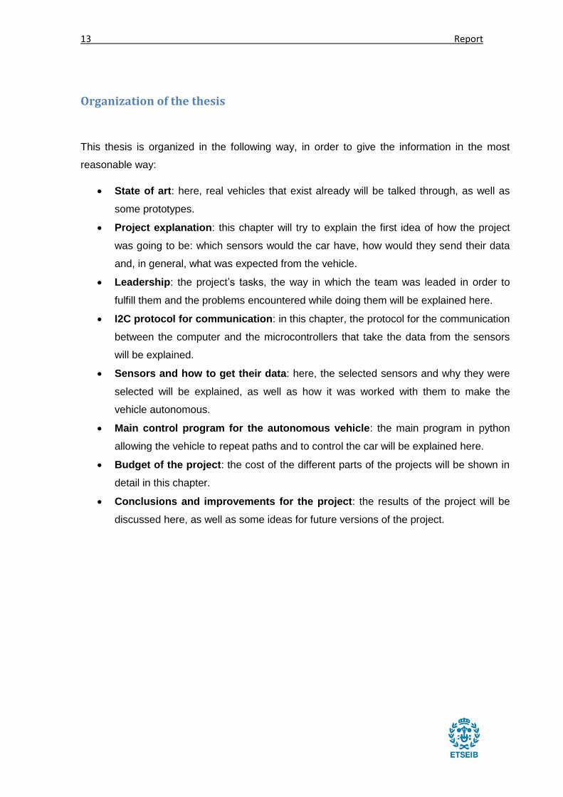
Organization of the thesis
This thesis is organized in the following way, in order to give the information in the most
reasonable way:
State of art: here, real vehicles that exist already will be talked through, as well as
some prototypes.
Project explanation: this chapter will try to explain the first idea of how the project
was going to be: which sensors would the car have, how would they send their data
and, in general, what was expected from the vehicle.
Leadership: the project’s tasks, the way in which the team was leaded in order to
fulfill them and the problems encountered while doing them will be explained here.
I2C protocol for communication: in this chapter, the protocol for the communication
between the computer and the microcontrollers that take the data from the sensors
will be explained.
Sensors and how to get their data: here, the selected sensors and why they were
selected will be explained, as well as how it was worked with them to make the
vehicle autonomous.
Main control program for the autonomous vehicle: the main program in python
allowing the vehicle to repeat paths and to control the car will be explained here.
Budget of the project: the cost of the different parts of the projects will be shown in
detail in this chapter.
Conclusions and improvements for the project: the results of the project will be
discussed here, as well as some ideas for future versions of the project.

Design and construction of an electric autonomous driving vehicle 14
State of art
When it is said that autonomous vehicles are the future it doesn’t mean they will start to be
done in the near future, it means that many groups across the world are investigating on and
some companies are already selling autonomous vehicles.
Throughout this chapter, many investigation groups and commercial products will be
explained in order to show how deeply this technology is already implemented in our
societies.
Navya ARMA
Autonomous shuttles are already being implemented in the airports of the world, being the
first one the Frankfurt’s airport, with its Navya ARMA bus. Navya, a French company focused
on these vehicles describes it as follows: “An autonomous, intelligent and electric shuttle at
the service of mobility.”
Figure 9: Navya's ARMA
This vehicle is 100% electric and is programmed to follow a predetermined route, with some
sensors to ensure it doesn’t collide against obstacles during its path, nor static nor dynamic

15 Report
ones. The sensors it carries consist on a GPS, a LIDAR, a stereovision camera and an
odometer. A remote control center monitors the vehicle’s movements and it has an
emergency braking system to be activated if needed.
The company explains that this product can be used in many different places, like industrial
zones, airports, theme parks, urban zones and even hospitals and hotel complexes to help
clients, visitors and workers to move more easily.
The Navya ARMA’s sensors consist on LIDAR, GPS, odometry sensors and stereovision
cameras and its batteries gives it an autonomy between 5 and 13h, depending on the
circulation conditions.
Figure 10: ARMA's functions on an airport
In Lyon (France), these shuttles from Navya are also going to be implemented for the public
transport. They are able to carry 15 people and they will be giving a last-mile service for
residents and workers for free with five stops in the 1350m of route. However, a human
operator will be on board all the time due to law restrictions.
They have a 45km/h top speed and are equipped with a LIDAR, a stereovision camera,
odometry sensors and a GPS. They will be integrated in the public transport network of Lyon,
since they passed the public safety requirements test and were approved for the use in
Design and construction of an electric autonomous driving vehicle 16
public roads. The French Agency for Environment and Energy Management and the Ministry
of ecology, sustainable development and energy are supporting the project.
Autonomous bus tests
However, Navya is not the only company to have built a bus-like autonomous vehicle;
Daimler Buses has already tested an autonomous driving bus in Amsterdam and the
Mercedes-Benz Future Bus drove autonomously more than 20km with a speed up to 70km/h
approximately, with a driver to monitor the system, in a transit line stopping at bus stops
precisely, respecting signals, going through tunnels and braking if obstacles or pedestrians
were detected.
Big cities around the world (San Francisco, London, Singapore…) are already working to
implement this technology into their streets when it comes available, even though it is going
to be difficult to do, since large investments in infrastructure will be required in order to
achieve this and other goals that will make a more efficient driving when added to
autonomous cars, like smart roads which will communicate with these vehicles during the
route.
Tesla’s founder Elon Musk forecasts future autonomous buses as smaller (which would help
reduce congestion) in size and taking passengers door to door. They will have their inside
space used in a more efficient way and the bus drivers will have to role of fleet managers.
The plan is to put in the market next year partial autonomous heavy-duty trucks and buses
that will “deliver a substantial reduction in the cost of cargo transport, while increasing safety
and making it really fun to operate", in Musk’s words.
17 Report
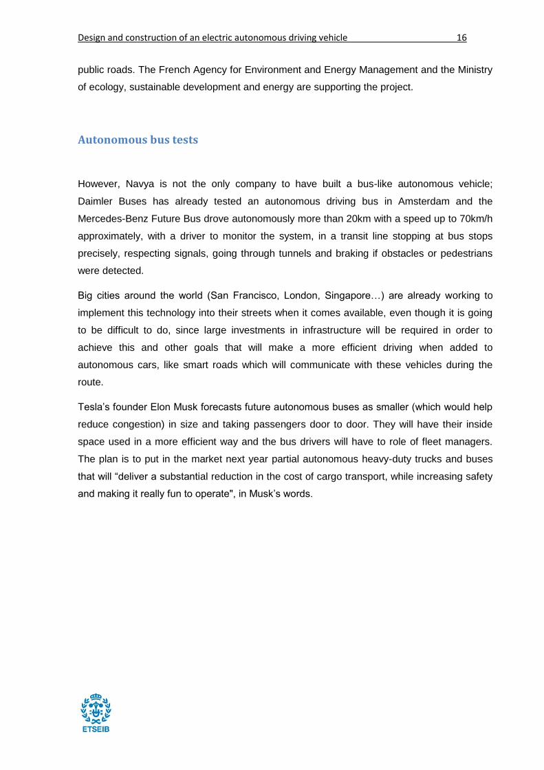
Figure 11: Autonomous vehicle in Donostia
In the European Union, 4 cities have been selected by the European Commission to test
autonomous buses: Lausanne (Switzerland), La Rochelle (France), Trikala (Greece) and
Donostia-San Sebastian (Spain). In the case of Donostia, the idea has been to test an
autonomous bus to help people move through the Scientific and Technologic Park of
Gipuzkoa, in which normal buses don’t enter and traditional vehicles are not efficient. Last-
mile service was needed for workers and visitors in this closed region, so these autonomous
buses built by Tecnalia were the best option and, also, a good way to start testing these
vehicles for the first time in Spain. In the near future, this technology is also going to be
tested in Barcelona by the UPC.
Figure 12: Autonomous shuttles

Design and construction of an electric autonomous driving vehicle 18
Another example of autonomous vehicles are the shuttles designed by the company
EasyMile, which will drive through Bishop Ranch, in San Ramon, where some very big
companies have their headquarters. They will travel slowly, though, since it’s a pilot program.
EasyMile has already installed some of these shuttles in Italy, Finland and Switzerland.
First autonomous cars
Figure 13: Tesla's Model X
Tesla will launch a new model of car in 2019 called Model X SUV, this time completely
autonomous and containing the so called “Hardware 2”. The actual cars, like the model X
shown in the image above, are only semi-autonomous (with a software called AutoPilot) and
have a group of sensors called by Tesla “Hardware 1”. These new cars will have many more
cameras and these will have heaters to fight problems that may arise due to ice or snow. In
the following image we can see how the cameras (as well as the ultrasonic sensors) are
going to be integrated in the vehicle.

19 Report
Figure 14: Sensors disposition in Tesla's Model X SUV
Frontal cameras will be in charge of detecting vehicles entering in the road lane without
telling it before, while the frontal-lateral ones will help in the intersections. The new lateral
cameras will help in the blind spots and will help making lane changes safer.
The new recognition hardware will be formed by:
8 cameras to control the 360º and with up to 250m long view range
12 ultrasonic sensors to complement the vision at low distances
1 frontal radar to have additional information in the front, which is also not affected by
rain, fog or even obstacles
Figure 15: Google's autonomous car

Design and construction of an electric autonomous driving vehicle 20
We can’t end the discussion on self-driven vehicles without mentioning Google’s
autonomous cars, which have travelled more than 2 million kilometers by using its LIDAR,
cameras, GPS and odometry sensors. This prototype is probably the most known example of
autonomous cars and the vehicle in which everybody thinks when thinking on future vehicles.
Present project
It can be seen that the sensors every big company focused on autonomous driving vehicles
uses are always the LIDAR, the cameras, the GPS and the odometry sensors. In the present
project, the GPS was not considered since the car would drive in small and closed places.
However, it was planned to be added on lately, like object detection algorithms for computer
vision and stereovision cameras.
21 Report
Project explanation
This vehicle was thought to work inside a controlled zone, far from pedestrians that could get
hurt by it and it should be used to move its passenger from one point to another as safely as
possible.
Sensors
With this statement in mind, the sensors that were considered necessary were:
6 Ultrasound sensor
4 Infrared sensor
4 Odometer
2 LIDAR
1 Camera
In the following images it can be seen a drawing made by the design team students in which
the possible look of the car and the position of the sensors seen from above are drawn.
However, later on in the project it was decided to put a single LIDAR in the middle of the front
part and to make it rotate 120 degrees by the use of a small servo motor, this way, all the
objects in the road at a maximum of 40 meters distance would be detected. For the near
obstacles, the ultrasound sensors would have them constantly detected in order to take the
required decisions without losing time.
Ultrasound sensors would have a detection distance of around 6 meters and a half and 30
degrees, while infrared ones would have only a 1.5 meters of detection distance in a narrow
arc, but being able to detect obstacles without dead zone (since the first centimeter), while
the ultrasound ones had a gap near the sensor where they would not be able to detect
anything. This was the reason for putting infrared sensors in the side: no obstacle was
expected to be very far on the sides, this was more probably going to happen in the front or
the rear. Since 6 meters was not enough to detect some obstacles when moving fast, the
LIDAR sensors where also considered. The main purpose for the camera was to detect
signals and follow the road, not to detect obstacles.

Design and construction of an electric autonomous driving vehicle 22
Figure 16: Initial idea of the autonomous vehicle
To take the data from the sensors, multiple PCB (Printed Circuit Boards) located strategically
in the car were considered as the best option. They would be separated in the following way:
2 in the front
2 on each side
1 in the back
Figure 17: Some Printed Circuit Boards

23 Report
Microcontrollers and their boards
The reason why these boards were thought to be put like this was to minimize the quantity of
cable that would go from the sensors to the PCBs, which would help to get less noise and
less voltage drop on them, helping to have a better quality signal. Since the boards were
going to have a low cost and could be made by members of the project, having 5 of them
was not a problem. The one on the back was to take the information of the ultrasound
sensors in the back, the ones in the sides were going to be near the wheels and receive
information from the infrared sensors, the odometers and, maybe, the sensors to measure
the compression of the suspensions. Finally, the 2 boards in the front where to take the
information from the ultrasound sensors (one of them) and for the LIDAR and to control the
servomotor attached to it (the other one). The last good reason to use many microcontrollers
was that, in this way, we could use the interrupts on them without fearing to end them (each
microcontroller had only 3 interrupts, which is usual in microcontrollers).
Another board was considered to be put in the roof, to take the data from the sensors that
could go there (LDR to measure the light, gyroscope, accelerometer, etc…) and to connect
the camera to it, but at the end it was considered not to use them and to connect the camera
extending its USB cable directly to the computer, which was going to be located below the
driver/passenger seat.
All these boards would have to send their data to the same microcontroller, which would then
work with it and pass it to the CPU through a USB connection. To send the data, it was
decided to use the I2C protocol, which will be explained later on in this project, to save cable
and communicate in an easy and fast way. It was considered that having 3 cables (Vcc, GND
and signal) for each sensor going through the car to the PCB from which the signals would
go to the computer was not ideal. Following the technical speaking, from now on the PCB
which would communicate with the CPU will be called master and the other ones, which will
all be identical, will be called slaves.

Design and construction of an electric autonomous driving vehicle 24
Figure 18: Schematic of the slaves PCBs
Figure 19: Schematic of the master PCB
These boards, which would be based on the microcontroller ATmega328P used in many
Arduino models like the UNO and the Nano, would take much faster the data if they only had
to take it from few sensors and this would give them time to calculate the required values
based on the values of the signals they received (pass from voltage to distance, for
example). This would effectively act as if the master had a much higher computation

25 Report
capacity. Also, needing fewer connections, both for the I2C communication and for taking
data from sensors, would allow making the PCBs much smaller.
Brakes and direction
Related with the mechanical part of the car, it was decided that it was going to have an
autonomous brake controlled by the main program, which would be responsible to decide
when to stop. This brake would consist on a linear motor which would press the brake fluid
when a signal was applied to it. However, for security reasons, it was also decided to put a
fully mechanical handbrake. It goes without saying that, even if the controller of the motor
has a signal to stop the motor, the car needs some brakes that actuate directly on the wheels
or the transmission will get damaged very fast.
Figure 20: Brakes of the car
In the photo above this text, both brakes can be seen (the handbrake one and the linear
motor to activate the one for the autonomous control). The following ones show how the
linear motor would press the brake fluid.

Design and construction of an electric autonomous driving vehicle 26
Figure 21: Autonomous brake
Figure 22: Brake fluid
Finally, to be able to control the direction of the vehicle from the computer, it was decided to
attach the steering column to the servomotor by a steel stick controlled by a solenoid. This
solenoid would be activated once the car started to work in autonomous mode and
disconnect when it changed to manual mode. The idea was that, if the passenger rotated the
driving wheel, pressed the accelerator pedal or used the selector to change the mode, the

27 Report
steering column would be disconnected from the servomotor and, therefore, it would be
much easier to make the car turn, since there would be no need to force the servomotor to
turn also. The stroke of the solenoid would enter in a hole in the steering column and make
the connection like this.
In the following photos, it can be seen the steering column with a steel stick inside, so the
steering column was always ready to be controlled by the servomotor.
Figure 23: Steering column

Design and construction of an electric autonomous driving vehicle 28
Figure 24: Metal piece connecting the servomotor and the steering column
As it can be seen, the initial idea was to have a vehicle able to detect obstacles and react to
them autonomously, but with the possibility to be manually driven. This way, if the car had to
go to somewhere that was not planned, it could do it without troubles.

29 Report
Leadership
The Russian student team for the autonomous car building was composed by near 30
students, which were separated in six groups by the three students who were from Barcelona
to lead them. Four of these sub-groups were related with mechanics and design, one was
related with electric systems and sensors and a group was related with the computation. All
the groups were in contact and knowing what was each other group doing, so they could
bring help to others when needed, while working in parallel to end the vehicle in the
scheduled time.
Since this project is about making a vehicle autonomous, only the last two groups are going
to be considered, being the electric systems and sensor one formed by 6 students and the
computation one formed by two students. It is important to note that, while the electric
systems group’s students were forced to participate in the project as a course from their
bachelor’s degree and the leaders were responsible of their marks, the students of the
computation group were from another school (although, part of the same university) and
decided to participate in the project moved by their own interest. One of them was working
and studying while participating in the project and the other one was doing a master’s
degree.
The computation group was in charge of programming the computer that would take the
decisions of the car and make it autonomous and the electric systems one had to design and
build the PCBs for the micros, as well as selecting the needed sensors, mount them, design
the sensor fasteners, build them and put them in the car.
Since the students of this university needed to participate in a project to obtain their
bachelor’s degree, most of them wanted to be in the formula student team. The students in
the team of electronics were no exception, but were forced to participate in the autonomous
vehicle project while being between 19 and 20 years old, except for two students: a student
who seemed motivated with the project and the old team leader, a girl who had the best
marks in her promotion and the only one to speak well in English. She also was the only
student of electronics engineering. This student, who seemed so motivated at the beginning
didn’t appear in the next 4 weeks, so he was put out of the project.

Design and construction of an electric autonomous driving vehicle 30
Figure 25: The true leader shows the path to follow
Parallel leading was tried when the project started, a way of leading which consists on not
sending orders in the vertical way, but from the same level. Here, the leader is another one in
the group, not a strict boss who forces people to work and do everything in his way. This way
of leading worked well with the computation group’s students, since they were more mature
and were more motivated. They also knew more about what they needed to do, so they felt
more useful and less apprentice, which is what everybody wants in the end. As the human
resources XY theory says: people want responsibilities and to feel useful.
With the students of the electronics group, everything was more difficult, since they were
always waiting to be told what exactly had to be done, they tended to wait to the end of the
timeline to do what they needed to do, many times it was not correctly done and they used to
complain about small things. The XY theory suggests that people are not lazy and that
everybody is willing to work hard, but only in things that motivate them, tasks that make them
feel useful, important…
It was not easy to motivate these students, who also considered cool the fact of not being
motivated, due to them being still teenagers. They started to be more serious once the sixth
student abandoned the project and they were told the leaders were going to put them their
marks. However, they were still letting the work for the last moment and not doing it always
as well as expected.
Ways to motivate them were thought and a good one seemed to be letting them choose the

31 Report
way in which things had to be done, taking decisions about their own work. For example,
they were asked to do the fasteners for the ultrasound sensors of the side of the car, but in
the way they considered to be better. However, they thought that this was due to the leaders
not knowing what kind of fastener they wanted or how a fastener had to be done.
With the computation group, it was easier to organize and to work, since they wanted to
participate in the project. Meetings were organized once per week to control what was each
one doing and to discuss about what should be done next. Also, to ensure each one was
doing a correct job, we all checked each other’s job. One of them preferred to work in the
more pure computation, focused on computer vision and the algorithm for controlling the car,
while the other one worked more with micros, sensors and pretty much anything that was
needed to do: one friday at night, while the car was being finished in the workshop, he was in
the laboratory creating a program to control the car with a radio control remote.
The only problem with them was they had so much work to do that they couldn’t spend too
much time on this project, especially at the end, which, as a result, didn’t allow the computer
vision algorithm to be ended in time.
Tasks partition
The tasks to be done to make the vehicle autonomous were initially separated in the
following way by the computation team and the author of this project:
Computer Vision:
Signal detection
Road line detection + view of the road from above
Sensors:
PCB schematic
Take data from LIDAR + control servo
Take data from accelerometer, gyroscope, LDR, compression sensor, pressure
sensor and temperature sensor
Take data from odometers
Take data from IR sensor + Ultrasound sensor
Take data from battery (voltage and temperature) and motor (speed, consumption)

Design and construction of an electric autonomous driving vehicle 32
Artificial Intelligence:
Program for the competition (follow the known trajectory)
Motor control
Trajectory control
Drive wheel control
Path selection
General decisions based on sensor data
Mounting:
Sensor protection
Decide sensors location
Sensor mounting
PCB and sensors holding
What do the elements in the list above mean and why it was decided to plan the project like
this at the beginning will be explained next.
As it can be seen, the initial idea was that the vehicle should be able to detect obstacles,
signals and the road and, based on that information, calculate the most adequate trajectory.
This was the ideal objective. However, before this was done, the vehicle would have to
compete in an autonomous vehicle challenge in which it should be able to repeat a trajectory
it had already followed.
As soon as the project started it was seen that, the problem which seemed like one of the
most difficult ones, the control of the motor, was already solved, since there was a controller
for the motor, which only needed some signals to know how to control the motor. For the
position of the steering wheel, a big enough to move the steering column servomotor was
used. With this servomotor we could know also how many degrees the steering wheel had
rotated.
With the odometers (wheel speed sensors), the distance travelled by the wheels would be
measured and it would be known how much the car had advanced. This way, it could be
known when the car was arriving to its objective to be able to accelerate or decelerate in
consequence. Using an accelerometer and a gyroscope to ensure the position was correct
was also considered. Between the main program, the odometers and the accelerometer and

33 Report
the gyroscope, it should be possible to get a very precise location of the vehicle at any
moment.
But, to be able to locate the sensors in the car, it was required where would be located and,
after that, design, build and mount the fasteners and protections for them. For the
odometers, the trigger wheels also had to be built, whose teeth would be detected by the
odometers and used to get information about the distance travelled and, with it, to know the
speed of the wheels.
Figure 26: Trigger wheel
Also, how many microcontrollers would take the data, where would they be located and how
would they communicate between them had to be decided. Once this was known, it would be
needed to make the schematics and layouts of the PCBs in which those microcontrollers
would be mounted on, as well as building them, with all the elements required to work. These
boards would also need some fasteners and protections to be located in the frame of the car,
which would need to be designed and mounted.
Adding more sensors to car was considered in order to get more information to know, for
example, if there is a passenger on board or not by measuring the pressure exerted on the
seat or the temperature of the motor and the battery. With more complete information, more
intelligent decisions could be made. For example, if the battery had a low charge, the vehicle
could start the return to an initial predetermined position.

Design and construction of an electric autonomous driving vehicle 34
The LIDAR sensor was a special case and was going to rotate by the action of a servomotor
located in the frontal part of the car. Since this sensor has a notable range, its task would be
to constantly check if obstacles appeared far from the car. Only the obstacles detected inside
the road would be considered.
Tasks distribution and problems appearance
The electronics team’s members were divided in order that, while one of them was designing
and building the fasteners for the frontal sensors, another one was doing the same with the
lateral ones, another with the ones in the back and, finally, the last two members of the group
would build the PCBs with the materials they were given and with the layouts as base. Later
on, one worked on the frontal trigger wheels, another one with the back ones, another one
with the fasteners for the battery, another with the path that the cables would need to follow
and designing its protection… When a task was too much for a single one to handle, more
than one student was assigned to it.
Unfortunately, the PCBs, which were expected to be very small resulted being too big and
some problems arised with them. Therefore, it was decided to buy small boards based on
Arduino Nano which could already perform beyond the required capabilities to fulfill the tasks
required by them. The frontal trigger wheels were also not designed correctly and needed to
be redesigned before making them.
The members of the group for the computation, as stated before, were one working on the
computer vision algorithm and the other helping to select sensors, testing them, programing
the algorithm to move the car… Dividing the tasks was easier with them, since they thought
by themselves into what could they do to help the project to advance.
Other problems appeared due to troubles with the communication, probably because the
language we used to communicate was the English and none of us was English native. Also,
some of them weren’t able to speak it very well. Due to this reason, sometimes a student
couldn’t understand the task assigned to him and ended doing a task which was already
being done by another one. Finally, the girl in the group, who could speak very well in
English, became the official translator for the group, which was really helpful and helped a lot
for the project and the exchange of ideas.
However, the biggest problem was not the language, but the fact that the project was not
strictly defined. Changes were constantly being made, some of them really radical, which
35 Report
forced us to constantly undo many hours of work and redo them in a different way. It is very
important to understand that, once it is decided that a project is going to be done, first of all it
must be decided how it is going to be, with the agreement of all the members and, once this
is done, continue with the original idea until the end, without doing any changes at all, ideally.
This way, projects can be finished, measured and discussed. Constantly changing parts of
the project does not allow to ever finishing it and we will always find improvements for all of
our projects.
This was the reason for the meeting that was done some time after the beginning of the
project, to which all the responsible people of the project went and in which the final shape of
the project was decided. However, to not organize the project with deadlines for the different
parts of the project had its consequences: some bottleneck processes were created. For
example, one of these problems was the programming of the board in charge of controlling
the motors, whose microcontroller crashed whenever information related with sensors was
asked. This information had to pass through this board and the fact that the program has this
flaw stopped the development of the autonomous part of the project. Another thing important
to remember is that the purchases of the elements required for the normal development of
the project must be done with enough anticipation to guarantee that they reach in time to be
used and not stop the advance of the project by this.
This meeting in which the problems of changing the project were faced gave the final shape
to what the project was going to be. At least in its first version.
Design and construction of an electric autonomous driving vehicle 36
I2C protocol for communication
At the beginning of the project, it was considered to send all the data of the analog sensors
to a single microcontroller, which would then send it to the computer to be treated there. The
problem here was that many cables would arrive to the board of that microcontroller from all
over the car, which was considered a bad idea later on. Then, other options were considered
and the I2C seemed to be best option from all the ones considered for the reasons that will
next be explained.
The options considered to be the protocols for communication in this project were the serial
communication protocol and the SPI protocol (Serial Peripheral Interface). The first one has
a low speed and, even though it only needs two cables, it can only communicate two
systems between them. On the other hand, the SPI protocol is very fast and allows to
connect as many slaves as we want to the master, but it requires an extra cable for each of
them.
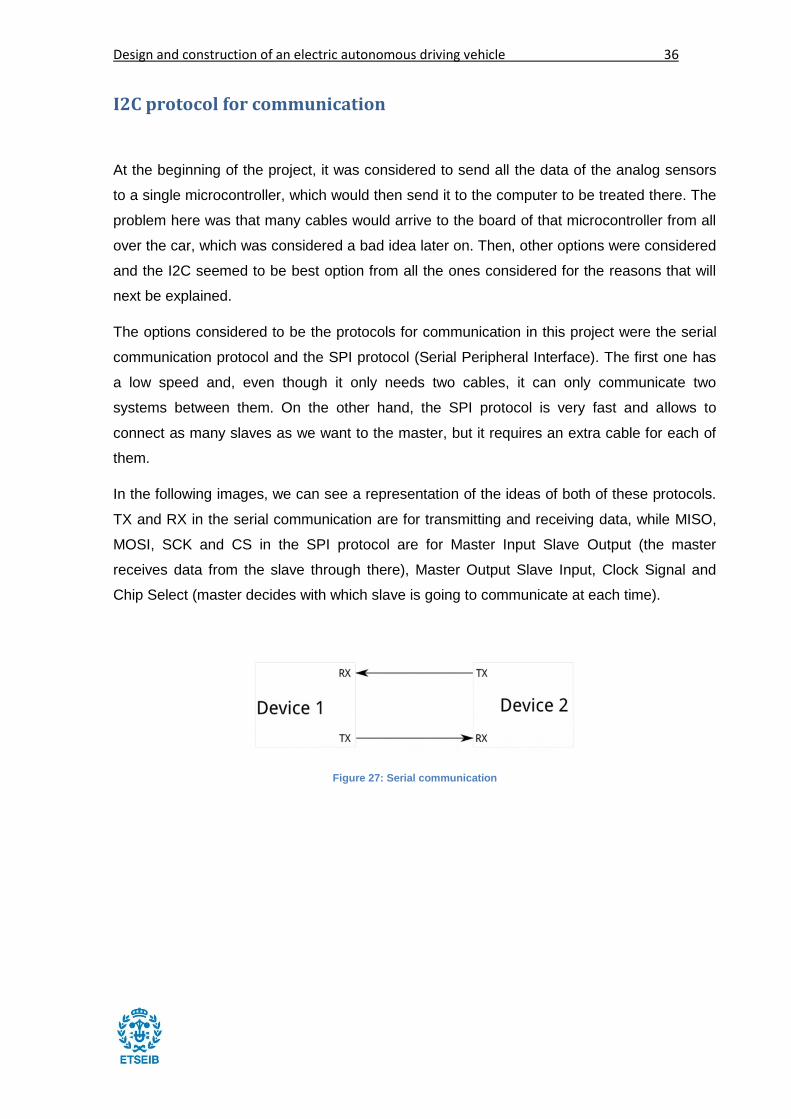
In the following images, we can see a representation of the ideas of both of these protocols.
TX and RX in the serial communication are for transmitting and receiving data, while MISO,
MOSI, SCK and CS in the SPI protocol are for Master Input Slave Output (the master
receives data from the slave through there), Master Output Slave Input, Clock Signal and
Chip Select (master decides with which slave is going to communicate at each time).
Figure 27: Serial communication

37 Report
Figure 28: SPI communication
So, what is the I2C protocol?
I2C (or I2C, standing for Inter Integrated Circuit) protocol is a fast protocol which requires only
two cables to communicate the master with all of its slaves: one for the timing and one for the
data transmission. This is a great advantage over both of the two protocols that have been
explained, which have its own flaws each one. As we can see in the image, the master uses
the SDA cable to decide the rate of the data transmission, to whose rhythm the master and
the slave will communicate. The supply and ground signals are not drawn, but are also
required, which means that 4 cables will be required in total for all the slaves: two for energy
supply (only the ground one is needed if the slaves are receiving the energy from another
element already) and two for communication.
Figure 29: I2C communication

Design and construction of an electric autonomous driving vehicle 38
So, how does the I2C protocol work?
The idea behind this protocol is very simple: a bit of information is sent every clock tick
to/from the selected slave from/to the master. In order to send the information, the SDA
signal (data cable) can only change when the SCL signal is low and must be stable when the
clock signal is high. In the image below, we can see that the SDA signal may be high or low
and, when the SCL becomes low, SDA can change and, again, it can be high or low.
Figure 30: How to send valid data through I2C protocol
The signals of the SDA cable are bidirectional and can go to the master or go from it. In order
to not send data from both sides at same time, first of all, the master has to tell the slaves
that the communication is going to start and, then, decide with which slave is going to
communicate. After that, it will tell if it will be the receiver or the transmitter of the data.
Finally, the communication can begin and will continue until the master tells that the
communication is over.
The reason why the SDA has to be stable while the SCL is high is because the start and stop
of communication are told during the SCL high time. To start a new communication, the SDA
signal must go from high to low while SCL is high and, to stop the communication, the SDA
must go from low to high while SCL is high. If a change occurred while SCL is high, the
communication would restart or stop.
Once the start condition has occurred, the bus is considered to be busy and cannot be used
by anyone (like another master) until a stop condition is fulfilled. Below, an image explaining
this process is shown in order to make it easier to understand.

39 Report
Figure 31: How to begin and how to end communication through I2C protocol
The first thing to do by the master when the communication has started, is to send the
address of the slave with which the communication is going to happen. Bit by bit, the unique
address of the selected slave is sent. Then, the slave must answer with an acknowledge
signal (ACK). After that, data will be sent and the receiver will answer to each bit with an
ACK bit until the communication stops. The image below shows the entire process of
communication using the I2C protocol.
Figure 32: Full explanation of the communication through I2C communication
The reason to pick analog sensors instead of the I2C communicating ones was due to them
having already their own addresses and, if more than one slave has the same address, the
communication won’t work, so we couldn’t take 2 sensors (or more) of the same kind. The
solution in this cases is usually to use an I2C multiplexor, but in this case, it would be
required to put cables from each sensor to the multiplexor and, to do that, the analog signals
can be used directly.

Design and construction of an electric autonomous driving vehicle 40
However, the I2C, even if being slower than reading some analog signals, allows to use only
three cables (one ground and two for communication, as said) for the entire vehicle and is
not limited in number (microcontrollers have a limited amount of analog inputs), so it turned
out to be a positive thing to use many slaves to take the data and to send it to the master.
Another advantage of using many microcontrollers is that, in this way, we don’t have any
limitations with regards to the interrupts we can use (with the ATmega328P, we only get 3
interrupts for each microcontroller).
Of course, as always, there are some pros and some contras. In this case, if the cables get
damaged, we lose the possibility to communicate with any device, which would not happen if
each device had its own cables. Also, the bigger the distance gets, the bigger the impedance
gets and the signal loses quality and high frequencies, which forces the communication to be
done to a slower rate.
Slave program for I2C
Below this lines, the basic program included in the slaves can be seen. The Wire.h library is
a library that allows us to communicate through I2C with simple instructions, like Wire.read(),
which lets read from the bus and get the data.
But, first of all, it’s important to talk about unions. A union, like the one seen at the beginning
of the program shown, is a special data type which allows to store more than one data type
in the same memory location. This means that we can save floats and bytes in the same
memory location, even with a different name. So, we can save float (decimal numbers,
positive or negative) data and work with it as a byte (1s and 0s).
Unions were required in order to send float information through I2C, so a union called
myData, containing the float floatData and the byte rawData (of the same size) was created.
This way, float data could be taken from a slave and send it as a byte through I2C. Later on,
it will be shown that same process required to be done in the master to recover the float from
the byte.
With the unions explained, the rest of the program consists on joining the I2C bus with an
address (from 1 to 7 for the slaves), to get the information from the sensors and to send the
float data as a byte whenever requested.

41 Report
Figure 33: Code to implement in the slave to work with I2C.
Master program for I2C
In the case of the master, the program is a little bit more complex. First of all, the speed of
the I2C communication has to be stated which, in the case of the ATmega328P can reach to
400kHz. Then, once in the main loop (in Arduino, void loop), a “for loop” is needed in order to
request data from all the slaves one by one, once and again.
To ask for data, the Wire.request() function is used, in which the size of the data expected is
included and then, if there is data available with that size, it is received as a byte type data.
Finally, this data is sent through serial communication to the computer as a float by the use
of the above mentioned union data type.

Design and construction of an electric autonomous driving vehicle 42
Figure 34: Code to be implemented in the master to work with I2C communication.

43 Report
Sensors and how to get their data
Schematics for the PCBs
To build the slaves and the master, first, the schematics have to be done, then the layout
and, finally, once everything is done, it can be proceed to build the PCBs.
For this project, the Arduino UNO board was taken as example which is free hardware, but
taking into account that the PCB didn’t need as many things as the UNO has and that I
needed to be as small as possible.
Following these considerations, the schematic for the slave shown below this text and the
one for the master after it were designed.
Figure 35: Slave's schematic

Design and construction of an electric autonomous driving vehicle 44
In this first schematic, it can be seen that only the crystal oscillator and the voltage regulator
were taken and, of course, to be able to work with them, some resistors, capacitors and
diodes. The rest are only signals, so a hole near the pin of the microcontroller and the route
to the pin should be enough for them. All in all, a very minimalistic PCB.
For the master, however, since it was going to need to communicate through USB with the
computer, it would need a USB port and an extra integrated circuit, apart from the extra
resistors, diodes and capacitors. This PCB would, therefore, be bigger than the slaves but,
since it was going to be near the computer in a protected zone with enough space for it, the
size didn’t matter as much.
Figure 36: Master's schematic
The layouts and construction was done by two students of the electronics team. However,
the result ended up being bigger than expected.

45 Report
Bootloader for the microcontrollers
To communicate through I2C and, in general, to make things easier, the Arduino IDE could
be used with the microcontrollers, since the ATmega328P is the microcontroller the Arduino
NANO and UNO use. This could save a lot of work that programming the I2C and the serial
communications in C could give. However, the ATmega328P microcontrollers can be sold
without the Arduino bootloader, which was the case in this project.
The bootloader is the group of instructions a microcontroller must follow when it starts and,
without it, the microcontroller is useless. Arduino has on its IDE a tool to burn (term used to
say install when related with a bootloader) the Arduino bootloader, which makes the process
easy to be followed. Also, in their webpage they have a tutorial explaining how to burn it
using an Arduino board and its ISP port.
Figure 37: Diagram of connection for burning the bootloader on an ATmega
Design and construction of an electric autonomous driving vehicle 46
Ultrasound sensors
In the end of the project, it was decided to not use the infrared sensors for the sides and to
change the model of the ultrasound sensor to a smaller one that could still detect obstacles
as far as 6.45m.
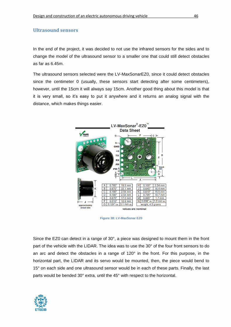
The ultrasound sensors selected were the LV-MaxSonarEZ0, since it could detect obstacles
since the centimeter 0 (usually, these sensors start detecting after some centimeters),
however, until the 15cm it will always say 15cm. Another good thing about this model is that
it is very small, so it’s easy to put it anywhere and it returns an analog signal with the
distance, which makes things easier.
Figure 38: LV-MaxSonar EZ0
Since the EZ0 can detect in a range of 30°, a piece was designed to mount them in the front
part of the vehicle with the LIDAR. The idea was to use the 30° of the four front sensors to do
an arc and detect the obstacles in a range of 120° in the front. For this purpose, in the
horizontal part, the LIDAR and its servo would be mounted, then, the piece would bend to
15° on each side and one ultrasound sensor would be in each of these parts. Finally, the last
parts would be bended 30° extra, until the 45° with respect to the horizontal.
47 Report
Figure 39: Explanation of the fastener for the frontal sensors
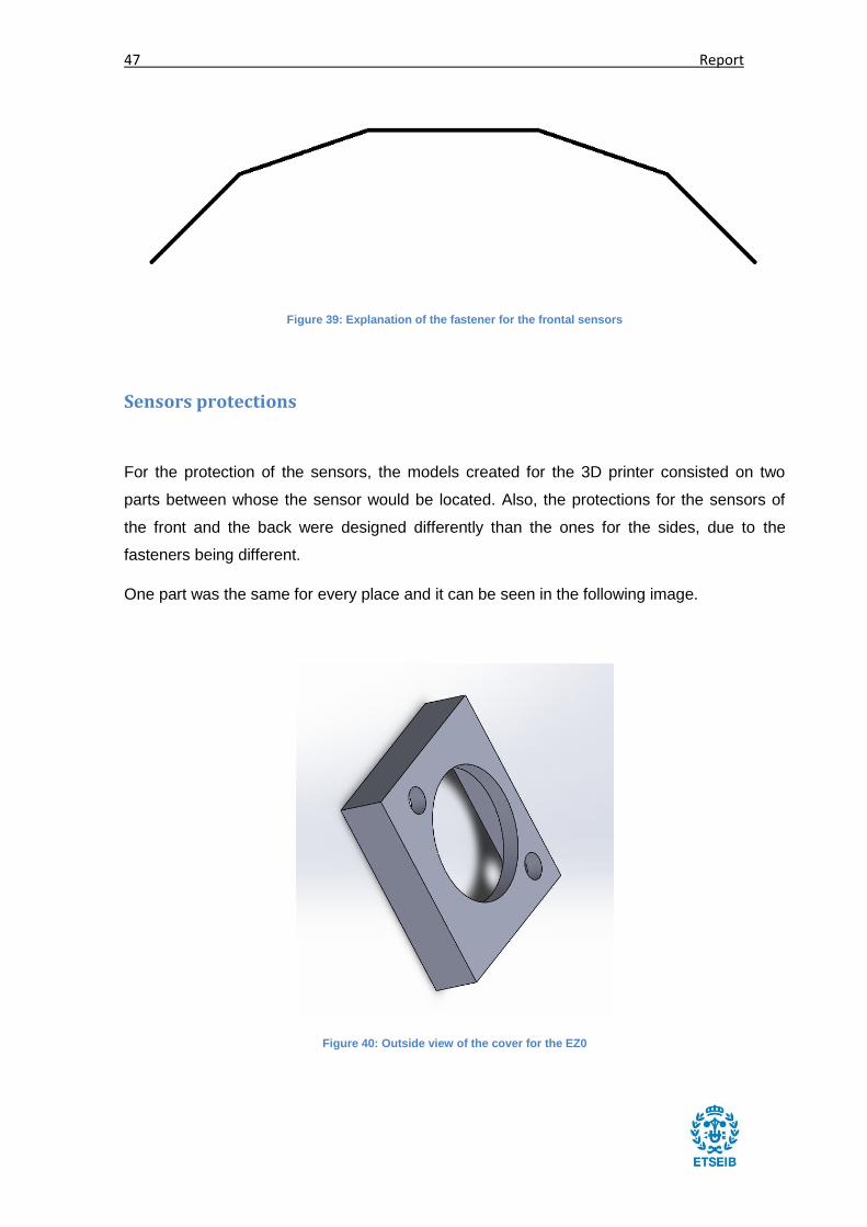
Sensors protections
For the protection of the sensors, the models created for the 3D printer consisted on two
parts between whose the sensor would be located. Also, the protections for the sensors of
the front and the back were designed differently than the ones for the sides, due to the
fasteners being different.
One part was the same for every place and it can be seen in the following image.
Figure 40: Outside view of the cover for the EZ0

Design and construction of an electric autonomous driving vehicle 48
Figure 41: Inside view of the cover for the EZ0
However, the other side could have either of the following forms, depending on if it was going
to be located on the side or not.
Figure 42: Back part of the protection for the lateral ultrasound sensors

49 Report
Here we can see the one for the lateral sensors, on which it can be seen that the part that
will be inside goes out a little bit in order to help placing these two pieces.
Figure 43: Back part of the protection for the ultrasound sensors in the front and back
Now, we can see the other version, used for the sensors that would go in the front and in the
back. It can be seen that here there is also a different height level in order to help positioning
this part with the other one.
In the following images, the fasteners in the side and in the back will be shown. The fastener
for the lateral sensor lost its painting due to the changes in the project and the one in the
back shows some small pieces that would need to be taken out later on.

Design and construction of an electric autonomous driving vehicle 50
Figure 44: Fastener for the lateral ultrasound sensors
Figure 45: Fastener for the ultrasound sensors in the back
51 Report
LIDAR and its servomotor
A LIDAR (Light Detection And Ranging) is a sensor which consists on a system sending a
laser beam and calculating the distance to the object by measuring the time the light takes to
return. There is a special data type called LAS created for them which consist on a cloud of
points that describes an entourage.
In this project, a sensor using the LIDAR technology (LIDAR Lite) was used in order to get
information from objects far away (until 40m). However, if the car was going to travel in a
road and was mounted on a servo which would turn 120 degrees, it could detect many
obstacles that weren’t on the road.
To know if an object should be taken into account or not, the following process has to be
followed, knowing that the road should not be wider than 4m.
Being R the distance at which the LIDAR can detect objects (40m maximum), H half of the
road (2m) and θ the angle the LIDAR has rotated, with the following equation we know the
angle at which R touches the side of the road and, from that point on, some objects may not
be considered.
𝑅 ∗ 𝑠𝑖𝑛𝜃 = 𝐻
Substituting R by 40 and H by 2:
40 ∗ 𝑠𝑖𝑛𝜃 = 2
𝑠𝑖𝑛𝜃 =2
40
𝜃 =2.9ᵒ
Of course, in a wider road, a bigger range will be considered in order to search for obstacles
in the full 40m of detection. In the following image, a representation of the reduction of R with
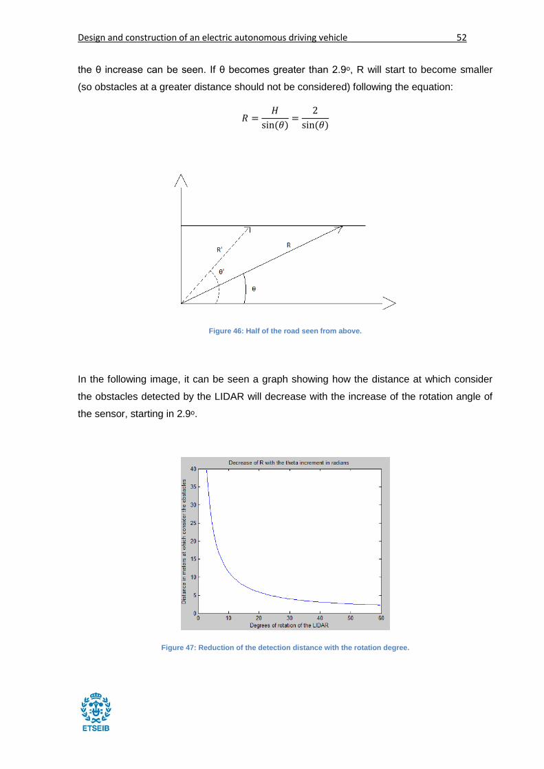
Design and construction of an electric autonomous driving vehicle 52
the θ increase can be seen. If θ becomes greater than 2.9ᵒ, R will start to become smaller
(so obstacles at a greater distance should not be considered) following the equation:
𝑅 =𝐻
sin(𝜃)=
2
sin(𝜃)
Figure 46: Half of the road seen from above.
In the following image, it can be seen a graph showing how the distance at which consider
the obstacles detected by the LIDAR will decrease with the increase of the rotation angle of
the sensor, starting in 2.9ᵒ.
Figure 47: Reduction of the detection distance with the rotation degree.

53 Report
So, in order to get the data from the LIDAR sensor, the servo on which it was mounted had
to turn and, then, take the data from it. Next, an image taken from www.robotshop.com will
be shown in which we can see a LIDAR Lite mounted on a servomotor of the same kind of
the one used in this project. This photo was selected due to the good quality of it, however, it
must be said that, in the present project, the same LIDAR Lite was mounted in a very similar
servomotor with a very similar fastener designed by the students of the electronics team.
Figure 48: LIDAR Lite attached to a servomotor.
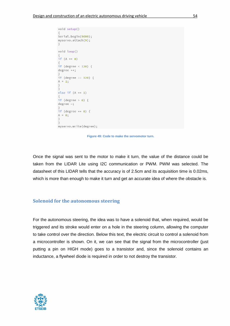
To make the servomotor turn, one of the students did the code, which consisted on making it
turn to one side or another depending on the value of a variable “A”, which had an initial
value of 1 and would change it whenever it reached to one end, the left or the right one.
Design and construction of an electric autonomous driving vehicle 54
Figure 49: Code to make the servomotor turn.
Once the signal was sent to the motor to make it turn, the value of the distance could be
taken from the LIDAR Lite using I2C communication or PWM. PWM was selected. The
datasheet of this LIDAR tells that the accuracy is of 2.5cm and its acquisition time is 0.02ms,
which is more than enough to make it turn and get an accurate idea of where the obstacle is.
Solenoid for the autonomous steering
For the autonomous steering, the idea was to have a solenoid that, when required, would be
triggered and its stroke would enter on a hole in the steering column, allowing the computer
to take control over the direction. Below this text, the electric circuit to control a solenoid from
a microcontroller is shown. On it, we can see that the signal from the microcontroller (just
putting a pin on HIGH mode) goes to a transistor and, since the solenoid contains an
inductance, a flywheel diode is required in order to not destroy the transistor.

55 Report
Figure 50: Diagram of the solenoid connection to a microcontroller.
In the following image, it can be seen a metal introduced in the hole of the steering column,
placed there in order to be able to control the car with the computer. However, since it would
not go out automatically, the driver should need to do an extra (but feasible by anybody)
force to turn the steering wheel.
Figure 51: Steering column of the car.

Design and construction of an electric autonomous driving vehicle 56
The elements of the system consisted on 1N4001 diode, a TIP120 darlington transistor and,
of course, the solenoid, which would require 12V in order to be able to work all the time
(nominal voltage). With 24V, it would only be able to work for 19 seconds and then, it would
need to stop for at least 57 seconds in order to not get damaged (duty cycle of 25%). The
bigger the voltage, the less time it could work and the more time it would need to stop.
However, since the microcontrollers and most of the electronic elements would need a
voltage of 12V or below, a voltage regulator was put near the battery of 36V.
Figure 52: Solenoid.
Wheel speed sensor
To measure the speed of the wheels and as odometers, Hall Effect wheel speed sensors
were used. These sensors are designed specifically for automotive applications and do not
require a magnet to trigger, they can detect a piece of metal. This piece of metal, called
trigger wheel, was designed by the electronics team, as it was said previously, and consisted
on a wheel with teeth fulfilling some minimum criteria which were given to them. The idea
was to detect the teeth whenever they passed in front of the sensor and to measure the time
elapsed between detecting one tooth and another. This process can be seen in the following
scheme.

57 Report
Figure 53: Scheme of the sensor working with the trigger wheel.
A Hall Effect sensor is a device which creates an electromagnetic field and measures the
current or the electromagnetic field to know if some magnetic element approached it or if a
metal is in front of it. They are usually similar to the one shown below, with a screw to stay as
fixed as possible, looking for a target.
Figure 54: Hall Effect wheel speed sensor.
Now, a program to read the signals received from the sensor when looking at a trigger wheel
will be explained. But, first of all, some important parts of will be discussed: the volatile data
and the interrupts. The keyword volatile before the data type tells the compiler that this
variable may change its value due to an external event, something that is not in this code. It

Design and construction of an electric autonomous driving vehicle 58
is necessary in order to not lose the data created on an interrupt. On the other hand, an
interrupt gets launched whenever the specified condition gets fulfilled in a pin prepared for
that. In the Arduino UNO and NANO, there are two interrupts to work with, the 0 and the 1
(digital pins 2 and 3). So, the program shown below gets in a loop waiting for the first rising
pulse received in the first interrupt pin and, whenever this happens, it receives the real time
in which it is. Later on, there is a falling interrupt, launched when the same interrupt detects a
fall from high to low voltage in the same pin and, then, it takes again the time, it does a
subtraction and sends the difference in time (the time during which a tooth was detected) by
serial communication to the computer.
Figure 55: Code to read the wheel speed.
Suspension compression measurement with flex sensors
Measuring the suspension compression can be very useful if the full state of the car wants to
be known. It tells if it’s braking correctly, it can help to control the car if wheels get blocked, it
helps understanding the errors in position produced…
Usually, for this purpose, linear potentiometers are used as analog sensors to know the
position. These sensors consist on a simple potentiometer, which is a resistor that varies its
resistance from a moving point to the most negative potential point when it changes its
length. These sensors are mounted with the suspension, having one side attached to it and

59 Report
the other side attached to a fixed point. If the suspension moves, a part of the potentiometer
will move the same distance and the microcontroller will receive that value.
It is important to note that, in order to not break it and to be able to measure the stretching of
a suspension, it needs to be mounted in an intermediate position, never fully stretched or
compressed.
Figure 56: Linear potentiometer.
In this project, another idea was considered. A flex sensor is a much cheaper sensor that
changes its resistance value when it gets bended. So, if one part was attached to a fixed
point and the other one to the suspension, when the suspension compressed, the sensor
would bend. As with the linear potentiometer, in order to not break it and to be able to
measure when the suspension stretched, the sensor was mounted already a little bit bended.
Figure 57: Flex sensor.

Design and construction of an electric autonomous driving vehicle 60
Main control program for the autonomous vehicle
The program to control the vehicle was decided to be done by versions, in order to test it part
by part and to ensure there was always a previous working version to work with, just in case.
The first programs to control the car were in C++, but it was later decided to work with
python, since it was better known by the members of the team and, also, it was easier to
code on it.
v1
The first version was called v1 and the idea was to make it a basic program, capable of
taking orders from a keyboard and, when told, to repeat them. The orders which would
receive would be, depending on the key pressed:
a: turn left
d: turn right
w: accelerate
s: decelerate
spacebar: brake/stop braking
g: save data/stop saving data
p: end of program
The cv2 library was used in order to take the data from the keyboard with its command
waitKey(), but this one required to create a window and have it selected while pressing the
keys, which was a bit confusing at the beginning.
Next, the code of the v1.py program will be shown. The cv2 library was only imported to take
data from the keyboard, as said, and the time library was required in order to use clock(),
which tells the time that passed until the function was called. Later on, if we call it again and

61 Report
we substract to the value received the one from before, we have the time elapsed between
both calls.
Then, a table is created to save the orders received and how long did they last. At the end of
the program, these results can be seen. This table has a defined size and, once its end is
reached, the values start to move to the left to let space for new orders, erasing the old ones.
The program starts already ready to save information and pressing “g” is required in order to
stop it from doing it, however, the time until the first command is sent is not saved. Also, the
window required to take data is created at the beginning and remains selected unless the
user clicks outside of it.
As expected, this simple program works well when launched in Ubuntu, however, the
“clock()” instruction doesn’t work in the same way in Windows and in Ubuntu. While in
Ubuntu it gives the real time in seconds, in Windows it gives the time elapsed since the last
time it was called in microseconds.

Design and construction of an electric autonomous driving vehicle 62
Figure 58: v1 program
We can now see this v1.py program working. The time until the first command was sent is
not saved in the table shown and these commands sent are shown with their equivalent char
number at the end of the program. Each time a command is sent, we can see its

63 Report
corresponding char number, followed by the key pressed and the time since the last key was
pressed in order to better see the table at the end.
Figure 59: v1 working
v2
The second version of the main program, called v2.py, had as objective to be able to send
orders to the motors through a USB communication with the microcontroller controlling them
and to repeat the orders received during the same amount of time and in the same order.
Here, when the program received a command from the keyboard, it would translate them into
a code that the microcontroller could understand.
Now, some parts of the full program will be shown and explained in order to better
understand how this v2.py program works.

Design and construction of an electric autonomous driving vehicle 64
Figure 60: Main part of v2
First of all, the main part of the program is situated above this text. It can be seen that, after
creating a window and initializing the serial communication with the microcontroller, the next
it does is send a command with the values 100, 2 and 0. These values are part of a code
implemented in the microcontroller.
In order to understand this code, it is necessary to explain some things:
Each number preceded by a dollar symbol is considered to be a new number. This
dollar symbol says that the number is in hexadecimal. Hex(100) = 0x64 = $64.
The first number can be either be a 64 or a 0. If it’s 64, we will ask for a steering
wheel movement.
The second number tells what to do (except turning the steering wheel, in which case
the first number is used), for example, $31 tells the motor to move forward.
Then, the third number tells the additional information like the speed required, etc…
To understand how the code works, some examples will now be shown:
$64$03$CF: turn the driving wheel to the position 3*256+207=975, the last possible
position in clockwise sense, turning in that sense until the end.
$64$00$30: turn the driving wheel to the position 48, the last possible position in
counter clockwise sense, turning in that sense until the end.
$31$70: motor inducing advancing movement with value 70.
$32$70: motor inducing reversing movement with value 70.

65 Report
$33$00: pull the brake (only one speed available and, therefore, the last number is
always 0).
$34$00: push the brake.
So, in the main part of the code shown before, we can see that, first of all, two commands
are sent: the first one to put the driving wheel in the middle ($64$02$00 or 100, 2 and 0) and
the second one to tell the motor to turn forward at 0 speed ($00$31$00 or 0, 49 and 0). Once
all this is done, it tells that the program starts saving data and enters in the main loop, which
consists on asking constantly for a new command and executing the order given. If 5
seconds pass without receiving any command and the program is not saving data (the letter
“g” has been pressed), the saved data will be sent again in the same order and during the
same time.
Next, one of the commands will be shown in order to better explain the process followed by
the program.
Figure 61: Acceleration function
Here, the idea is that, when the acceleration key is pressed:
If the car has a negative or null speed and, with its increment it goes to 0 or a greater
positive number, the motor changes it sense.

Design and construction of an electric autonomous driving vehicle 66
If the car has a speed that doesn’t reach to the minimum one and is asked to
accelerate, it goes to the minimum speed.
If the speed in the reverse sense is smaller than the minimum minus 20, it becomes
0.
If the required speed is greater than the maximum, the value of the speed is the
maximum.
In any other case, the speed just grows.
Finally, the command is sent, a message is shown explaining which is the new speed and, if
“g” has not been pressed (or pressed and, then, pressed again), it saves the command and
the time passed for the last command, which is since it was pressed until now. The maximum
value for the speed is 255, the minimum is 90 (with less than 70 the motor doesn’t have the
strength to even move the wheels) and the increment in the speed value each time the
acceleration key is pressed (“w”) is 5.
The send_command instruction is very easy to understand: if the first number is a 0, it sends
the second and third numbers, if not, it sends all three of the numbers through the USB port
to which the system is connected.
Figure 62: Send_command function
The table explained before is included now, with the values of the keys taken as chars. As it
can be seen now, the character “d” is the number 100 and so on. Therefore, when a
character is asked in the main part and a command is ordered, the char value of the said
character is compared with these and, if its equal to any of these, the order is sent as seen in
the accelerate() function.

67 Report
Figure 63: Select_action function
At the end of the program (when the key “p” is pressed), the program shows all the saved
values, stops the motor, closes the window required to send the commands, ends the USB
communication and ends the program.
Figure 64: End_program function
As done with the v1.py program, it will now be shown the v2.py program in action.

Design and construction of an electric autonomous driving vehicle 68
Figure 65: v2 working
Here it can be seen how, once the program is not saving data and a character is not
inserted, after 5 seconds the actions are repeated in the same order and, even if the time is
not shown when repeating the actions, at the end of the program, the table from which the
actions to repeat are taken shows also the time during which the program has to wait until
the next action is sent.
v3
The third version of the program was called v3.py and the idea here was to read the
information given by the sensors and to take decisions based on it, like stop the movement if
an obstacle is detected near the vehicle and to stop acting autonomously whenever a human
wants to take back he control on the vehicle. The functions here would be separated in order
to make the program easier to read and called whenever they are required.

69 Report
Figure 66: Importing functions
We have just seen the function asking for the data that the car controlling PCB handles. As it
can be seen, now it is needed to import send_command as if it was a library and, from it, the
send_command() function has been called.
Computer vision
In this project, a computer vision algorithm wasn’t implemented in the main algorithm, since
there was not enough time to develop it completely. However, there was a camera with
which some trials were done and an algorithm to work with OpenCV in python computing
language.
This algorithm made by the member of the computation team working on this was able to
detect that there were traffic signals and it was able to detect some of them in real time but,
even if this was possible for a small quantity of signals, it turned out to be difficult to work
with all the signals, since they were too many and this would slow down the main program
too much.
Using a database limited to the signals the vehicle was going to face was proposed, as well
as using a neural network which would learn the signals and then would not need to be
searching for matchings, but none of these was finally implemented.
Related with the road detection, there were a pair of programs done in Matlab: one for
detecting the road lines in a conventional road and another one to detect the asphalt based
on the textures and/or the color.

Design and construction of an electric autonomous driving vehicle 70
The first of these two programs has an evident deficiency: what happens if the road has no
lines? Lines could be painted where the car was going to move, but this would ask for an
extra work. However, it looked like the best option when we take into account the second
one.
The second program has bigger deficiencies: what happens if the texture or the color are not
equal in all the places where the car is going to move? Dirt roads and routes are very
different if we take into account the color or the texture. Also, what if the car had to move in a
place where all the floor was similar? In a case like that, an entire road would need to be
painted, which is worse than just painting some lines. Anyway, these algorithms had to be
adapted to work with OpenCV in python and try if they worked in real time and were not too
slow, since Matlab is a program that is useful for doing tests, but it is not fast at all.
In the trial zone for the car in the Moscow’s university, the floor was all asphalt and there
were no lines, which was a real challenge to test this algorithms there. Painting some lines
seemed like the most feasible way to do it (apart from being the most used option for this
kind of vehicles).
Figure 67: Road lines detection by the use of computer vision

71 Report
Budget of the project
The budget of this project does not take into account the hours expended by the students
leaded in this project or the materials that the Polytechnic University of Moscow allowed us to
use, like iron (for the fasteners), welder (for welding the fasteners), machinery (for building
the fasteners, trigger wheels and sensor protections), energy and materials for welding or the
places to work and to test the vehicle.
Taking into account that the vehicle was given and the software used for developing the
autonomous part of the project was free software (pycharm, Arduino IDE, Code::blocks,
sublime, AlgorithmBuilder, KiCad and OpenCV), the cost to make a vehicle autonomous
looks lower than it could really be.
For the cost of the time invested by the author of this project, an annual salary of 27,000€,
including the Social Security, which in Spain is 30%, and 1650 annual working hours, which
makes total cost of 16,36€ per hour invested.
For the cost of matlab, which has an individual licensing of around 2000€, 5 years of
amortization were considered, giving a cost of 400€/year. Also, since the project was
developed in just about 6 months, the cost of matlab for this project was 200€.
The cost of the elements bought with Russian rubles was calculated in euros using the
official exchange rate of the day the budget was done. Also, the elements required for
building the PCBs and the system to pass to autonomous driving using the solenoid will be
stated as a single element, in order to not make the costs list too extensive.
Finally, in “other costs”, the cost of flying to Moscow from Barcelona, the cost of the visa and
the international assurance were included.
Therefore, the complete list of the elements considered and their price is the following one:

Design and construction of an electric autonomous driving vehicle 72
Figure 68: Costs of the project

73 Report
Sustainability and environmental impact
For the environmental impact, many things must be considered: the environment, the society
and the economy. Next, all three of these options will be considered in relation with the
present project.
Environmental impact
Building metallic vehicles has always a high environmental cost for the material extraction
required and the high energetic cost required to give form to it. If we add the electronic
elements, the batteries, and all the plastics that are in a car, we can see that their production
cost is quite high in environmental terms.
However, another very important cost is the energy supply for the vehicle. In the case of the
autonomous vehicles of the present and the near future, since they are fully electric, the
pollution is going to be greatly reduced. Even if producing the electricity required for them to
move is polluting, it is always considered to be less polluting to do it in a single place, rather
than extending it, which is what usual cars do.
Apart from the fact that they are usually (but may not be) electric powered, there is the
certainty that, the smoothest we drive and the shortest the path we follow, the less we
consume and, therefore, the less we pollute. Autonomous cars point is that they drive better
than humans. If they didn’t, this technology would not make any sense to develop. And
driving better not only means being safer, but also more smoothly and following the shortest
paths. Also, when the smart cities arise, the roads, as other vehicles and signals, will
communicate with the autonomous cars, which will help ending with traffic problems as they
will tell them when any problem occurs in their path.
Autonomous cars, and vehicles in general, will pollute less and, therefore, will be much more
environment friendly.

Design and construction of an electric autonomous driving vehicle 74
Social impact
People are getting more and more interested in promoting transportation means which can
allow them to travel wherever they need as fast as possible, but without being stopped by
their economic conditions or disabilities and while being harmless for the environment and
not dangerous for other people.
Automation in driving is a key area to look for in this contest, since it will reduce the accidents
and less time will be lost inside them, since they will know the best path. They will also give a
greater autonomy to people with handicaps, since they will not need to drive them.
Therefore, a completely different society may emerge with their appearance, one in which
everybody will be able to move freely and in which nobody (or practically nobody) will die in
the roads. One in which moving will be very cheap and in which they time spent commuting
will be spent doing other things we may like.
Economic impact
However, the arrival of these vehicles may not only change the way in which we move, it
may also change the way in which we possess our vehicles to a society in which we share
our vehicle or use another person’s one. Since these vehicles will not be driven by persons,
they will be able to drive the entire day, moving people from one point to another one, which
will be a great change, since today’s personal vehicles work only the 4% of the time, as
some people estimate. These new ways of possession with relation to motor vehicles are
called alternatives for mobility. All in all, they seem like the solution to the commuting
problem.
Robin Chase, Zipcar co-founder said: "[My wish] is that people can imagine not owning cars,
a completely shared transportation system where they don't spend 18 percent of their
household income on their car. Once we have people imagining it, then we'll push to make it
happen." This idea has been stated also by Travis Kalanick, founder of Uber, who thinks that
companies like his will allow people to move cheaply whenever they need it without needing
to own a car with the implementation of autonomous cars. Anthony Foxx, U.S. Secretary of
Transportation, expressed that we might be the last generations to drive a car.

75 Report
In fact, alternatives for mobility’s objective is that people stop owning vehicles, without losing
the freedom and flexibility that owning a car gives to us and which allows us to, for example,
arrive to our workplace when there are no public transportation to cover the route, due to it
being far from a city or due to the hours at which we work.
The most evident alternative is to share vehicles to arrive to places when we are going to the
same place. Working colleagues are the clearest example, but companies like blablacar help
people to find somewhere to carry or to be carried by when they need to travel to another
city. This is always cheaper and, since less cars are used, it allows to pollute less and have a
more fluid traffic. This idea is closely related with the car pooling concept, which consists on
filling the cars as much as possible to, for example, avoid parking and traffic jams. The
Universitat Autònoma de Barcelona calculated that vehicles entering in its enclosure had, as
a mean, 1.11 people inside them, a very low number which made arise the problems
mentioned before.
Another alternative, which will appear with the autonomous vehicles, will be that your car
belongs to a shared fleet and that it can be called to search you through a smartphone app,
for example. The car will come to take you and bring you wherever you want while you use
the time you are inside it on whatever you prefer, like playing, working, reading… People will
be always passengers and the inside of the car will be designed with that in mind.
Once the cars are autonomous and shared, they will be like public transport, they will be paid
for each travel made on them. Companies like Uber and Tesla have already planned to buy
very big fleets to offer this service in the future, but there is also the possibility that the
owners will allow other people to call their cars to get some money from it, which will help
them to pay for it. We only need to wait to the regulators to approve these vehicles and, from
there on, the future.

Design and construction of an electric autonomous driving vehicle 76
Conclusions and improvements for the project
In the end, the vehicle was able to be driven as a normal electric car with its steering wheel,
its pedal and its brake, by computer, with the keys said before, and, if driven by computer,
the car would also be able to repeat the orders received in the same order and during the
same time, so it was able to repeat any trajectory it had followed before and, therefore, to
drive autonomously.
However, the battery could give some problems at certain times, due to the BMS being
prepared for lower current outputs. A BMS is a controller for the battery and its task is to cut
the current output if too much of it is drained. However, in this project, the servomotor, which
controlled the steering column, would need a lot of current and, if the vehicle was moving
with some speed, the current could be cut. Changing the BMS or the entire battery should be
done in a near future to greatly increase the capacities of the vehicle.
Figure 69: A battery with its BMS
Also, since most of the sensors arrived a bit late, the full algorithm couldn’t be done in time to
consider their information and take decisions based on them, it would only brake if an
obstacle was detected. So, finishing the v3 algorithm (the one which would use their
information in order to take decisions) should also be finished, which would make it able to
drive more autonomously. The car should be able to slow down if an obstacle is detected
and try to pass around it or react in the required way. Also, there was the idea of the car

77 Report
saving the trajectory in a .txt to read it later and be able to repeat the path after restarting the
computer, but it couldn’t be made in time.
In relation with the computer vision, as stated before, there was a program to detect road
signals and a program to detect the road was being worked on. The camera was also bought
and the fastener was already welded and painted in the car. The program containing the
computer vision algorithm was called v4, but was never implemented in the car since it was
only driven inside the university, where there were no roads (it is important to know in which
kind of road it’s going to move in order to prepare the algorithm for it), no signals (small
signals were used and focused with the camera to ensure the functionality of the program)
and, due to other problems, this part was left for later.
Figure 70: Fastener for the camera
Detecting the distance to the obstacles or detecting human (or animal) beings by the use of
computer vision could be a direction in which to continue, but this should be done in a
second version of the project. Also, LEDs or even a small screen could inform about the
state of the car.
Another problem detected was the I2C communication, which could be slower than expected
due to the impedance of the long cables. Having many boards connected with the same
cables could also mean that, if the cable gets damaged, the communication will be lost with

Design and construction of an electric autonomous driving vehicle 78
many sensors and, maybe even with all of them. Therefore, and as seen later on, having
many cables could be an option to take into account for the next version of the project.
Finally, some improvements could have been done in other aspects of the car, like its outside
image, which was not ended. But, all in all, the project, consisting on building an electric car
able to drive autonomously reached to the end satisfactorily and the team could proudly
present its work.
Figure 71: The final autonomous vehicle

79 Report
Bibliography
Websites
[1] Website of Google’s autonomous car. (2017-01). Retrieved from https://waymo.com/
[2] Website of Navya. (2017-01). Retrieved from http://navya.tech/
[3] I2C protocol explanation. (2017). Retrieved from http://i2c.info/
[4] Union data types explanation. (2016). Retrieved from
www.tutorialspoint.com/cprogramming/c_unions.htm
[5] Website of Arduino. (2017-01). Retrieved from www.arduino.cc
[6] Network of question-and-answer websites for electric engineering and programming.
(2017). Retrieved from www.stackexchange.com
[7] Honda’s vision about safe and efficient mobility. (2017-01). Retrieved from
http://www.hondadreams.es/2016/01/04/el-coche-autonomo-hacia-una-movilidad-sostenible-
eficiente-y-segura/
[8] How Tesla’s autonomous car work. (2016-10). Retrieved from
http://www.xataka.com/vehiculos/para-pasar-del-autopilot-a-la-conduccion-autonoma-en-los-
coches-de-tesla-hace-falta-hardware-2
[9] How to communicate a master with 5 slaves through I2C. (2014-03). Retrieved from
http://www.techbitar.com/how-to-network-many-arduinos-with-sensors-using-i2c.html
[10] Semiautonomous vehicles today and autonomous vehicles future. (2016-01). Retrieved
from
http://www.howtogeek.com/233073/what-are-autonomous-cars-and-when-will-i-have-one-in-
my-driveway/
Design and construction of an electric autonomous driving vehicle 80
[11] How the self-driving cars work. (2014-06). Retrieved from http://robohub.org/how-do-
self-driving-cars-work/
[12] White House’s Frontiers Conference. (2016-10). Retrieved from
http://www.popsci.com/frontiers-conference-future-urban-transportation
[13] First autonomous bus trials in the world. (2016-07). Retrieved from
https://www.buses.org/news/article/the-cutting-edge-autonomous-buses-coming-to-a-road-
near-you
[14] The first autonomous buses in the United States. (2015-10). Retrieved from
http://gizmodo.com/the-uss-first-autonomous-buses-will-drive-around-a-cali-1734989938
[15] Autonomous bus trial in Donostia-San Sebastian. (2016-02). Retrieved from
http://www.expansion.com/economia-
digital/innovacion/2016/02/10/56bb76fae2704e18418b45fa.html
[16] Autonomous buses in Lyon. (2016-09). Retrieved from
https://eandt.theiet.org/content/articles/2016/09/lyon-launches-fully-electric-autonomous-
public-bus-service/
[17] Elon Musk’s vision for autonomous trucks. (2016-07). Retrieved from
http://www.dezeen.com/2016/07/28/elon-musk-vision-autonomous-buses-updated-tesla-
master-plan-part-deux/
[18] Sustainable commutation. (2015-07). Retrieved from
http://www.xataka.com/tecnologiakia/car-sharing-y-las-alternativas-para-una-movilidad-mas-
sostenible
[19] Tesla’s master plan in a nut. (2016-07). Retrieved from
http://www.adslzone.net/2016/07/21/tesla-sera-una-empresa-energia-renovable-camiones-
coches-totalmente-autonomos/

81 Report
Documents
[20] JAN ERIK SOLEM, Programming computer vision with python, 2012.
[21] STEPHEN P. ROBBINS, DAVID A. DECENZO, Fundamentals of management:
essential concepts and applications. (Harlow: Pearson Education Limited). 2015.
[22] JESUS FRAILE MORA, Máquinas eléctricas. (Madrid: McGraw-Hill Interamericana de
España, S.A.U.). 2008.
[23] ALLEN B. DOWNEY, Think Python: How to think like a computer scientist. (Needham:
Green Tea Press). 2015.
[24] JÖRNSEN REIMPELL, HELMUT STOLL, JÜRGEN W. BETZLER, The Automotive
Chassis: Engineering Principles. (Oxford: Butterworth-Heinemann). 2001.
[25] Mathias Perrollaz, Raphäel Labayrade, Cyril Royère, Nicolas Hautière, Didier Aubert,
Long range obstacle detection using laser scanner and stereovision. (Laboratoire sur les
Interactions Véhicules-Infrastructure-Conducteurs, LIVIC). 2006.