Embed Size (px)
Citation preview
ATD: The Autonomous Test Driver
An Autonomous Driving System for Test-Track Vehicle Evaluation
Ryan Stevens
4997-2893
EEL5666: Intelligent Machines Design Lab
Department of Electrical and Computer Engineering
University of Florida
Instructors
Dr. Arroyo
Dr. Schwartz
Teaching Assistants
Mike Pridgen
Thomas Vermeer
4/20/2009

Stevens, 2
Table of Contents
TABLE OF CONTENTS ..............................................................................................................2
ABSTRACT....................................................................................................................................3
EXECUTIVE SUMMARY ...........................................................................................................4
INTRODUCTION..........................................................................................................................5
INTEGRATED SYSTEM .............................................................................................................6
MOBILE PLATFORM .................................................................................................................8
ACTUATION .................................................................................................................................9
SENSORS .....................................................................................................................................10
BEHAVIORS ...............................................................................................................................16
EXPERIMENTAL LAYOUT AND RESULTS........................................................................17
CONCLUSION ............................................................................................................................18
APPENDIX (Program Code) ......................................................................................................19
Stevens, 3
Abstract:
The following report outlines the design guidelines associated with ATD: the Autonomous Test Driver. ATD’s design allows it to navigate a walled course quickly, utilizing fast integrated sensors to detect the course with a high degree of accuracy and predictive learning of the course on a rudimentary level to improve the driving lines of the robot. Once it is done learning the sequence of turns in its first lap of the course, ATD will drive the course aggressively, attempting to complete it as quickly as possible. ATD was planned to be controlled by an Atmega128 microcontroller integrated with a custom IR rangefinder array, commercial range finding sensors for wall following, an accelerometer for driving feedback, and a gyroscope to record information about the course turns. It contains LCD and LED feedback for debugging and demonstration purposes. Due to constraints with components, time, and money, ATD was successfully implemented with commercial IR sensors and the gyroscope as its main sensors. The custom IR rangefinder array, while working in prototyping, did not work at production time. Crude course mapping and a slight increase in speed were able to be implemented as a result.

Stevens, 4
Executive Summary:
ATD is an autonomous test driving mobile agent. It is based on a 1/18th scale R/C Car chassis and utilizes a variety of sensors to detect a walled course and drive through it as quickly as possible. The project encompassed a fusion of mechanical and electrical designs to accomplish this goal as effectively as time, money, and design difficulties could allow.
Expenses in terms of electronics accounted for a significant bulk of the project’s cost, and required the procurement of extensive prototyping supplies. These expenses were compounded by size requirements of the small robot, which dictated that more expensive and compact equipment was purchased. In terms of engineering design, significant failures include issues with a special sensor that prevented its inclusion in the robot, and a lack of time in fully implementing a faster driving algorithm.
Currently, ATD is capable of driving around a closed course at a moderate speed. Following its detection of a completed lap, it stores information about the turns it made in the first lap into memory, and increases its speed in an attempt to drive the course even more quickly. Following detection of two “lap markers” in rapid succession, it slows to a stop, and displays the turn data it had obtained in the original lap. Future work will hopefully improve upon the design of ATD and lay a stronger foundation for autonomous driving.

Stevens, 5
Introduction
As automobile manufacturers strive for vehicles that maintain both high performance and exceptional fuel economy, the requirements of automotive testing become more and more stringent. With component and system complexity ever increasing, the probability of an individual failure impacting the overall vehicle performance is increased as well. To aid manufacturers in the testing of these vehicles, an autonomous test driving system would allow the manufacturer to test vehicles on various track designs without risking human life in an accident, and allow the vehicle to be driven to its limits precisely, and repeatedly, in order to assess component wear and vehicle performance.
A small autonomous car, named ATD, was constructed to meet these objectives. ATD drives around a walled course, and attempts to drive it as quickly as possible. This robot will provide a small-scale solution to this problem, and will also lay the groundwork for a possible full-scale robotic platform in the future. The following documentation outlines the specifications and design of ATD: the Autonomous Test Driver.
Stevens, 6
Integrated System
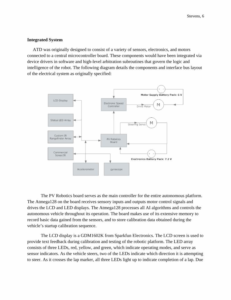
ATD was originally designed to consist of a variety of sensors, electronics, and motors connected to a central microcontroller board. These components would have been integrated via device drivers in software and high-level arbitration subroutines that govern the logic and intelligence of the robot. The following diagram details the components and interface bus layout of the electrical system as originally specified:
The PV Robotics board serves as the main controller for the entire autonomous platform. The Atmega128 on the board receives sensory inputs and outputs motor control signals and drives the LCD and LED displays. The Atmega128 processes all AI algorithms and controls the autonomous vehicle throughout its operation. The board makes use of its extensive memory to record basic data gained from the sensors, and to store calibration data obtained during the vehicle’s startup calibration sequence.
The LCD display is a GDM1602K from Sparkfun Electronics. The LCD screen is used to provide text feedback during calibration and testing of the robotic platform. The LED array consists of three LEDs, red, yellow, and green, which indicate operating modes, and serve as sensor indicators. As the vehicle steers, two of the LEDs indicate which direction it is attempting to steer. As it crosses the lap marker, all three LEDs light up to indicate completion of a lap. Due
Stevens, 7
to issues with software overhead, during the driving phase the LCD will not be used as it effectively slows down the control loop.
The primary sensor system will be an array of individually tuned IR rangefinder emitter/detector pairs. Each sensor will receive IR reflections of a transmitted square wave at a specific tuned frequency. The intensity of this reflection will indicate the relative distance from the reflecting surface. Each element of the array will contain additional circuitry to filter and interface the sensor outputs to the microcontroller. This sensor will be used to visualize the course ahead of the robot, as the driving algorithm will require a high amount of sensory data to properly maneuver the course. Due to issues with construction, this sensor was not completed. The analog circuitry worked as expected, but coupled noise from an unknown source on the receiver board effectively negated effective operation. The circuitry was thus abandoned near the end of the semester in favor of using successfully operating sensors to accomplish the same behaviors, but with reduced capability.
For wall-following and rear obstacle avoidance, commercial Sharp IR GPD12DY rangefinders will be used in pairs on either side of the robot. This arrangement will allow the vehicle to precisely align parallel to a wall, and allow it to drift closer or farther from a specific wall. These sensors will be used to avoid side obstacles. As well, they will allow the robot to prepare for upcoming turns by maneuvering to the outside wall prior to entry to the turn.
The servo and drive motor serve to maneuver the robot around the field. The servo is a standard R/C hobby servo, and controls the Ackermann steering mechanism of the car chassis. The DC drive motor applies power to the rear wheels and is controlled via the electronic speed controller (ESC). The ESC is a hobbyist digital-proportional motor controller that is controlled by outputs from the microcontroller. It applies the proper voltages to the drive motor to run it at various speeds.
The accelerometer is a MEMS device that is used to provide PID feedback control for the robot. Rather than use a shaft encoder, the motor control feedback is based on the positive or negative acceleration detected by the accelerometer. This allows the autonomous agent to accelerate or decelerate precisely. As well, a running summation of these values allows the control algorithms to have an idea of the relative velocity of the vehicle. The gyroscope allows the vehicle to record the sequence and relative angle of each turn on the course. This sensor is critical to allowing the robot to maneuver quickly through the course on successive laps. Experimental testing of the accelerometer indicates that vibration from the motor provides a source of noise. As a result, both of these sensors will be filtered by running average filters implemented by the Atmega128. While this smoothed gyro output, it did not fully stabilize the accelerometer, and the negligible enhancement to operation resulted in a complete removal of the accelerometer from the software system. Both of these devices were connected to the PV Robotics board utilizing a SPI enabled MAX1113 ADC chip.
Stevens, 8
The power distribution system consists of two separate battery packs. The main drive motor battery pack is a 7.2 V NiMH battery pack used solely to drive the main DC Motor. The second battery pack is a 7.2 V NiMH battery pack which provides the power for the steering servo and the main electronics package. Two on/off switches allow either of these supplies to be engaged independently of each other. One of these switches is mounted on the ESC, while the other is directly mounted on the wooden superstructure.
In addition to these devices, a CDS cell and LED illuminator were added to detect the presence of a black strip of tape along the ground. The CDS cell was connected via a simple voltage divider into one of the ports on the MAX1113 ADC originally used for the accelerometer. Utilization of this sensor allowed the robot to detect when it had completed a lap, as well as allowing ATD to detect two strips of tape in rapid succession and use this condition as a stop trigger.
Mobile Platform
The design of a curving, winding test track present special difficulties in mechanical platform design. The vehicle must be able to turn precisely while driving forwards, and be able to perform both small and large turns without having to resort to stopping to complete the maneuver accurately. Utilizing a platform with the same mechanical design as a modern automobile would satisfy these requirements and allow the electronics and mathematics of the robot to be directly scalable to a full size vehicle.
In order to fulfill these requirements, the mobile platform consists of a 1/18th scale R/C Car Chassis, the Team LOSI Mini-T. This chassis contains spring suspension, an Ackermann steering mechanism, and a rear-wheel differential drive train. These mechanical systems allow the platform to maneuver as a real car maneuvers, and allows it to brake, accelerate, and turn simultaneously in a smooth fashion. This mechanical platform provides the best solution to the kinematic challenges of driving a winding course at high speed.
Furthermore, the mechanical platform contains a wooden superstructure attached to the four latch-pin posts on the Mini-T chassis. This portion of the chassis is built of sheet metal, and reinforced with a supporting bracket that fits underneath the drive motor battery pack on the car chassis, and provides additional vertical support. The atmega128 board, LCD screen, accelerometer/gyroscope, and Sharp IR rangefinders are mounted on the superstructure. The transmitter portion of the special IR sensor array, which is fully functional, is also mounted on this superstructure. The CDS cell and illumination LED were added to the main chassis of the robot, with a small wooden board on top of the two to reduce the effects of ambient lighting on the cell.
Stevens, 9
Actuation
ATD contains two main actuators: the steering system, and the drive-train. These two actuations must work in concert together to accelerate in a straight line, maneuver through a turn, and avoid obstacles. The steering linkage is actuated by a small R/C servo, an HS-55, which was installed in place of the original 4 wire servo, which lacks control circuitry. The drive-train is powered by a small DC motor which was pre-installed in the chassis.
The steering mechanism is an Ackermann steering linkage. In this type of steering the servo rotates to slide a direct linkage which is connected to the front wheels themselves. This rotates the front wheel mounts to allow the vehicle to turn either left or right. The amount of servo rotation affects the turning radius of the vehicle at any given moment. However, this type of steering mechanism is constrained in that it is dependent upon forward or reverse motion of the vehicle itself. As a result, turns must be initiated with some non-zero vehicle velocity. Further complicating the steering, the velocity of the vehicle has some impact on the turning radius as well.
As a result of these complexities, the servo will be controlled by PWM output from the microcontroller via a turning arbitration subroutine. This subroutine will ensure that proper velocity is maintained entering, and exiting the turn via communication with the rear-wheel drive control subroutine. Output of the PWM signal will adjust the servo’s position, and allow for very precise control of ATD.
The rear-wheel drive system is the second actuation present on ATD. This drive-train links the output of the DC motor to a series of gears, a slipper clutch, and a rear-wheel differential and its associated output shafts. This mechanical system serves to allow the motor to apply torque and accelerate the vehicle while allowing the individual rear wheels to turn at different angular velocities. This arrangement minimizes slip during turns, and ensures that all four wheels will maintain grip on the driving surface during most maneuvers. While braking via driving the motor in reverse was considered, it was not necessary at the speeds and scale that ATD operates at. To decelerate, simply leaving the motor at zero power will allow ATD to come to a quick stop. This was experimentally verified using the remote control system that came with the Mini-T. As a result, all actuation of the drive-train will be controlled via the PV Robotics board, which will send control signals to the ESC to accelerate the motor or let the robot coast to a stop. While a PD controller involving the accelerometer was considered, uncontrollable noise on the accelerometer due to motor vibration, and the stability of the ESC negated its requirement in the overall control system.

Stevens, 10
Sensors
The sensor suite of ATD was specifically designed to utilize the optimum sensors for each sensing task. As the robot will travel short distances at higher speeds, typical data acquisition rates must be higher than 10 Hz. As a result, data is evaluated in a decision making process at nearly 40 Hz to allow the vehicle to respond rapidly.
Special Sensor:
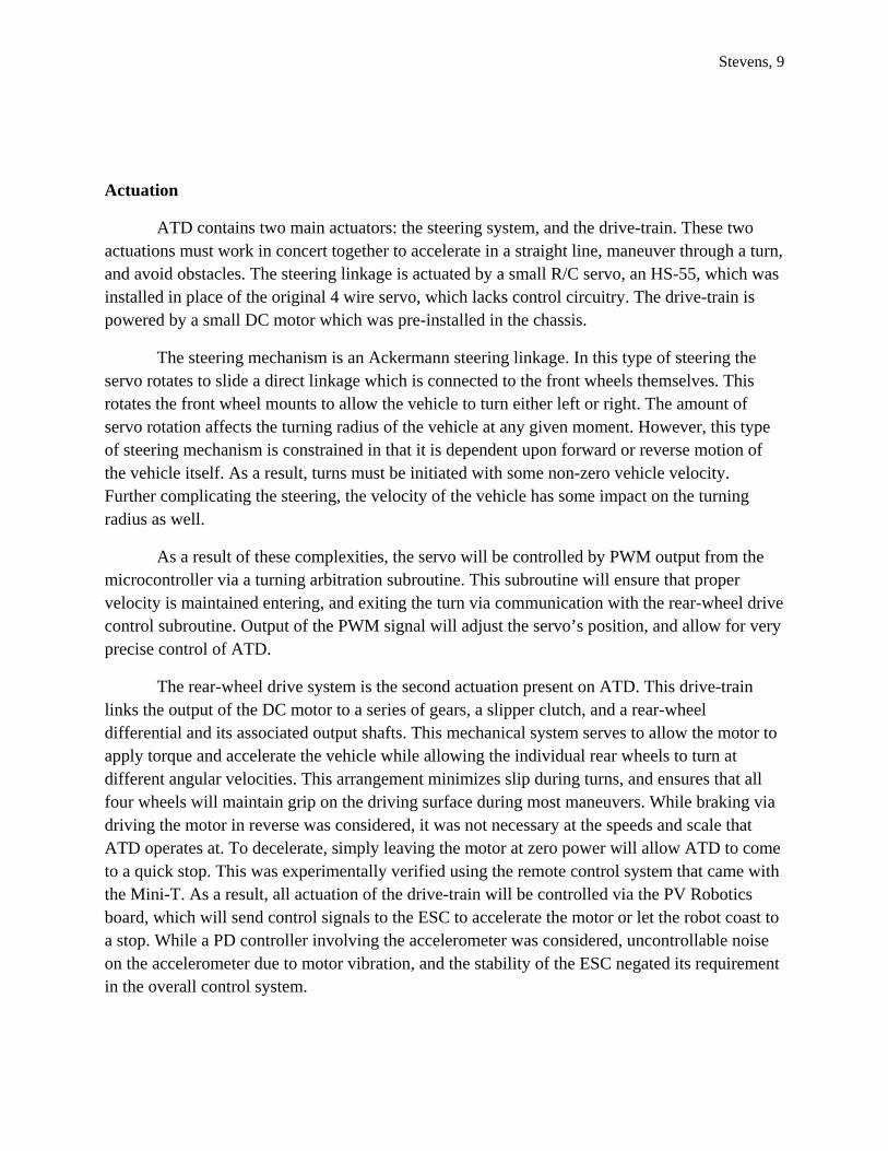
The primary sensor system is the IR rangefinder array. However, this system had problems when transferred to PCB designs, and was not implemented. The array would be mounted on the front of the wooden superstructure, and contain 5 IR rangefinder channels in a hemispherical array. The sensor utilizes IR LEDs and IR phototransistors to transmit a square wave in the IR light spectrum, and output a voltage level proportional to the reflected light captured by the detector. The Radio Shack emitter detector pair proved to be well matched compared to the other equipment evaluated, and was selected as the primary IR component. The system contains 5 discrete channels ranging in frequency from 10 kHz to 500 kHz. A sample 555 timing circuit is presented below:
Stevens, 11
Figure 2-1: 555 Timer circuit for Square Wave Generation
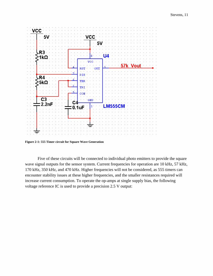
Five of these circuits will be connected to individual photo emitters to provide the square wave signal outputs for the sensor system. Current frequencies for operation are 10 kHz, 57 kHz, 170 kHz, 350 kHz, and 470 kHz. Higher frequencies will not be considered, as 555 timers can encounter stability issues at these higher frequencies, and the smaller resistances required will increase current consumption. To operate the op-amps at single supply bias, the following voltage reference IC is used to provide a precision 2.5 V output:
Stevens, 12
Figure 2-2: 2.5 V Reference using AD680AR IC
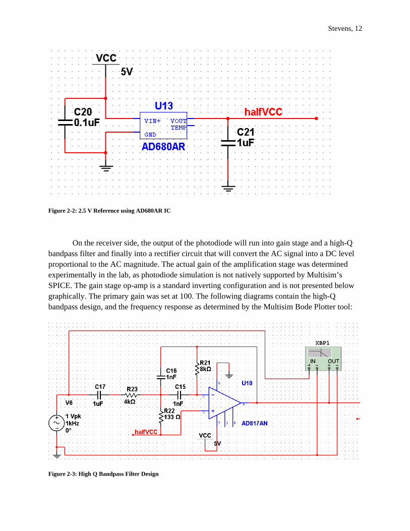
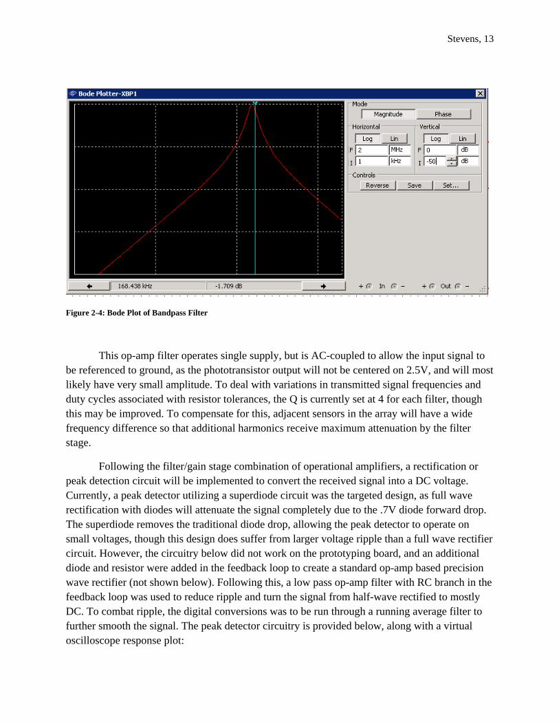
On the receiver side, the output of the photodiode will run into gain stage and a high-Q bandpass filter and finally into a rectifier circuit that will convert the AC signal into a DC level proportional to the AC magnitude. The actual gain of the amplification stage was determined experimentally in the lab, as photodiode simulation is not natively supported by Multisim’s SPICE. The gain stage op-amp is a standard inverting configuration and is not presented below graphically. The primary gain was set at 100. The following diagrams contain the high-Q bandpass design, and the frequency response as determined by the Multisim Bode Plotter tool:
Figure 2-3: High Q Bandpass Filter Design
Stevens, 13
Figure 2-4: Bode Plot of Bandpass Filter
This op-amp filter operates single supply, but is AC-coupled to allow the input signal to be referenced to ground, as the phototransistor output will not be centered on 2.5V, and will most likely have very small amplitude. To deal with variations in transmitted signal frequencies and duty cycles associated with resistor tolerances, the Q is currently set at 4 for each filter, though this may be improved. To compensate for this, adjacent sensors in the array will have a wide frequency difference so that additional harmonics receive maximum attenuation by the filter stage.
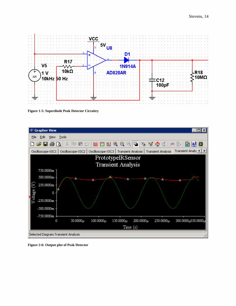
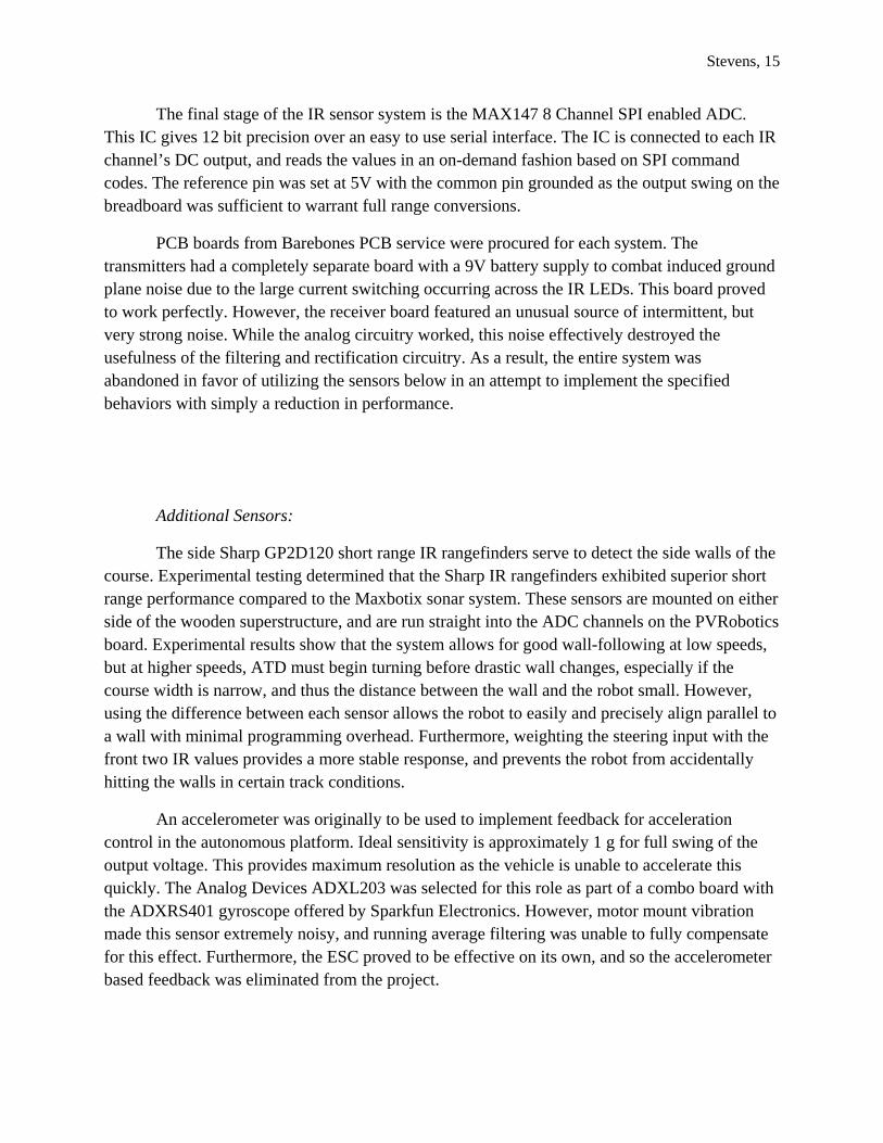
Following the filter/gain stage combination of operational amplifiers, a rectification or peak detection circuit will be implemented to convert the received signal into a DC voltage. Currently, a peak detector utilizing a superdiode circuit was the targeted design, as full wave rectification with diodes will attenuate the signal completely due to the .7V diode forward drop. The superdiode removes the traditional diode drop, allowing the peak detector to operate on small voltages, though this design does suffer from larger voltage ripple than a full wave rectifier circuit. However, the circuitry below did not work on the prototyping board, and an additional diode and resistor were added in the feedback loop to create a standard op-amp based precision wave rectifier (not shown below). Following this, a low pass op-amp filter with RC branch in the feedback loop was used to reduce ripple and turn the signal from half-wave rectified to mostly DC. To combat ripple, the digital conversions was to be run through a running average filter to further smooth the signal. The peak detector circuitry is provided below, along with a virtual oscilloscope response plot:
Stevens, 14
Figure 1-5: Superdiode Peak Detector Circuitry
Figure 2-6: Output plot of Peak Detector
Stevens, 15
The final stage of the IR sensor system is the MAX147 8 Channel SPI enabled ADC. This IC gives 12 bit precision over an easy to use serial interface. The IC is connected to each IR channel’s DC output, and reads the values in an on-demand fashion based on SPI command codes. The reference pin was set at 5V with the common pin grounded as the output swing on the breadboard was sufficient to warrant full range conversions.
PCB boards from Barebones PCB service were procured for each system. The transmitters had a completely separate board with a 9V battery supply to combat induced ground plane noise due to the large current switching occurring across the IR LEDs. This board proved to work perfectly. However, the receiver board featured an unusual source of intermittent, but very strong noise. While the analog circuitry worked, this noise effectively destroyed the usefulness of the filtering and rectification circuitry. As a result, the entire system was abandoned in favor of utilizing the sensors below in an attempt to implement the specified behaviors with simply a reduction in performance.
Additional Sensors:
The side Sharp GP2D120 short range IR rangefinders serve to detect the side walls of the course. Experimental testing determined that the Sharp IR rangefinders exhibited superior short range performance compared to the Maxbotix sonar system. These sensors are mounted on either side of the wooden superstructure, and are run straight into the ADC channels on the PVRobotics board. Experimental results show that the system allows for good wall-following at low speeds, but at higher speeds, ATD must begin turning before drastic wall changes, especially if the course width is narrow, and thus the distance between the wall and the robot small. However, using the difference between each sensor allows the robot to easily and precisely align parallel to a wall with minimal programming overhead. Furthermore, weighting the steering input with the front two IR values provides a more stable response, and prevents the robot from accidentally hitting the walls in certain track conditions.
An accelerometer was originally to be used to implement feedback for acceleration control in the autonomous platform. Ideal sensitivity is approximately 1 g for full swing of the output voltage. This provides maximum resolution as the vehicle is unable to accelerate this quickly. The Analog Devices ADXL203 was selected for this role as part of a combo board with the ADXRS401 gyroscope offered by Sparkfun Electronics. However, motor mount vibration made this sensor extremely noisy, and running average filtering was unable to fully compensate for this effect. Furthermore, the ESC proved to be effective on its own, and so the accelerometer based feedback was eliminated from the project.
Stevens, 16
The gyroscope serves a critical role in the sensor suite of ATD. The gyroscope’s primary purpose is to record angular change during the initial lap of the course. This data will allow ATD to record the sequence of “soft” and “hard” turns that comprise the course. With this knowledge, ATD will be capable of modifying its route on successive laps to better drive the course quickly. The ADXRS401 gyroscope from Analog Devices proved to be a successful gyroscope for this application. Running average filtering was implemented in software, and thresholds were used to determine which turn ATD was making at any instant.
The CDS cell was added to detect the lap marker and to identify a set of black lines to indicate a request to stop ATD. It was wired up with a voltage divider, and placed at the base of the robot. As the robot drives around the course, it is able to detect the lap marker with a high degree of accuracy.
The CDS cell, and gyroscope are interfaced with a SPI enabled MAX1113 ADC from Maxim IC. This system acquires the data at 1000 Hz and implements eighth order running average filtering on the gyroscope. All other sensor data is acquired at 40 Hz using a data acquisition clock onboard the PV Robotics board.
Behaviors
There are three main behaviors associated with ATD’s tasks. The first and primary task is the drive algorithm. This algorithm would interpret data from the forward and side sensor arrays to avoid walls and navigate the turns of the course. This algorithm is constantly computing a weighted summation of the forward two sharp IR rangefinders and the differences between the left and right Sharp IR rangefinders. This weighted summation drives the steering servo through a steer subroutine that accounts for the mechanical limits of the servo mount. This subroutine is running continuously in the main operation loop and constantly updates the servo position accurately. Drive motor control is accomplished through another subroutine that sets the PWM control for the ESC to a specified percentage of full power.
The second behavior is the initial lap drive, which is initiated at startup. Following calibration of the sensors, ATD will begin driving the course. As the robot slowly navigates the course, this behavior will indentify and record the sequence of the first ten turns the robot completes. Following completion of this lap, the behavior will hand off arbitration of the robot to the second high level navigation behavior.
The second main navigation arbitration behavior is the speed lap driving algorithm. In this algorithm, due to time and programming constraints, the speed of the drive system was the only noticeable feature increased. An attempt to utilize gyro acquired turn data to improve
Stevens, 17
turning was pursued but was unable to be completed in time. As a result, the robot improves its speed marginally on the subsequent laps. The course size, being exceptionally small, however, limits this speed increases severely.
In addition, a stop behavior was added to ATD. If ATD detects two black tape markers within a short period of time, it will turn its motor off, and coast to a stop. Following this, it will print out the sequence of turns it recorded in the first lap. Currently, the sequence is capped at the first 10 turns, though this is acceptable for the current course sizes used in demonstrations. This behavior works excellently, and allows an observer to easily stop ATD by simply quickly laying down another piece of tape near the lap marker. This also allows for a demonstration of a discontinuous track which better displays ATD’s capability to map the first ten turns of a course.
Experimental Layout and Results
Experiments were performed to determine the speeds at which ATD was to operate during demonstrations. The following qualitative assessments were made:
Speed Value Evaluation
15 Moderately fast, stable on small courses 16 Faster, slightly less stable, occasionally fails on
small courses >= 17 Unstable, extremely prone to crashing on small
courses
As a result, ATD was programmed to drive at 14% power during the initial slow lap and 15% during the faster lap. Due to the nature of the ESC controller at lower power ratings, this speed increase is actually far more significant than the 1% indicates, as the response is non-linear.
As well, the CDS cell thresholds were determined for both NEB and for Benton Hall. At Benton hall, a value of -40 was sufficient for operation, due to the white floor. However, at NEB, the multicolor floor presented a problem. The black tile appeared so close to the black tape, and
Stevens, 18
the differences in values between black tape on black tile, and black tape on white tile, forced a modification to the track. The CDS value was set at -25, and the black tile was covered with white poster board and white printer paper. This was the only option as no sufficient threshold could be determined for the case of all three types of tile. However, ATD works perfectly over the burgundy and white tiles, and still displays robust operation over a wide operating environment. In the case of NEB, a very specific and non-ideal case presented itself that could not be compensated for in software or hardware without field modifications.
During testing on the walled track, it was determined that a white coat to each block would significantly improve IR reflectivity. After this track change was implemented, ATD’s performance around the turns at slower speeds became very consistent. However, the course layout must be carefully designed, as with the limited wood available only a very tight, very compact course can be built. As a result, for ATD to complete the course effectively, some amount of course engineering must be employed when laying out the track, as ATD can simply not turn hard enough to execute turns within a certain turning radius.
Conclusion
The design proposal described above laid a solid foundation for the initial design of an autonomous test track driver. The ATD project provided the opportunity to develop a robust robotic platform capable of driving a complex course quickly. This not only provided a proof of concept for autonomous driving agents, but also developed a scaled prototype of what could be developed into a full-scale autonomous driving system for a modern automobile.
ATD realistically accomplishes partial functionality of its original intended goals. It can drive around a closed course, increase its speed marginally, and establish crude turn mapping whilst driving. However, it is not exceptionally fast, nor does it make use of a custom IR rangefinding array. Despite these limitations, it does manage to establish a strong proof of concept of an autonomous test-track robotic platform.
The usages of commercial Sharp IR rangefinders exceeded initial expectations, and were able to effectively resolve drive inputs for ATD at moderate speeds. Had more time been allotted, and the special sensor fully debugged and operational, these capabilities would have been capable of implementing more advanced driving.
Future work in this area of robotics should focus on continued development of advanced, high capability IR sensors that, if successful, offer significant improvements in terms of course detection and resolution. As well, specifications for motor control systems will need to be

Stevens, 19
revised, as accelerometer based feedback turned out to be marginally useful, and noise in this system was extremely difficult to overcome. Furthermore, emphasis on larger course designs that approximate scale models of actual race tracks would significantly improve testing and performance, as the current track options are simply too small to allow effective operation of a 1/18th scale car.
Appendix
Note: Program code included is only the code which was written by the author. PV Robotics code was not supplied, but can be found by referencing manufacturer datasheet. Including all of the files would be beyond the scope of this paper.
ATD_Wallfollow.c (main program)
#include <avr/io.h>
#include <avr/interrupt.h>
#include "PVR_Servos.h"
#include "LCD.h"
#include "sleep.h"
#include "ADC.h"

Stevens, 20
#include "drive.h"
#include "math.h"
#include "SPI.h"
#include "LED.h"
/*This is the ATD_Wallfollow code as of April 2009
*It uses the PVR_V2 code from Pridgen Vermeer as a baseline
* - Ryan Stevens */
//CDS Defines
//Threshold set for NEB Rotunda, threshold for Benton = -40
#define CDS_THRESHOLD -25
//Gyro Defines
#define RIGHT_THRESHOLD 30
#define LEFT_THRESHOLD -30
//#define HARD_RIGHT_THRESHOLD 40
//#define HARD_LEFT_THRESHOLD -40
char TURNS[10] = {5, 5, 5, 5, 5, 5, 5, 5, 5, 5};
char TURN_FLAG = 0;
char TURN_COUNT = 0;

Stevens, 21
//Global Variables (L, R) Back is ADC1,3, Front is 0,2
//SHARP VARIABLS
int IR_LEFT_BACK = 0;
int IR_LEFT_FRONT = 0;
int IR_RIGHT_BACK = 0;
int IR_RIGHT_FRONT = 0;
//int SPECIAL_IR_RIGHT = 0;
//int SPECIAL_IR_LEFT = 0;
//SHARP OFFSETS
int IR_LEFT_BACK_OFFSET = 0;
int IR_LEFT_FRONT_OFFSET = 0;
int IR_RIGHT_BACK_OFFSET = 0;
int IR_RIGHT_FRONT_OFFSET = 0;
//ACCELEROMETER VARIABLES
//int AVG_ACCEL_LONG_AXIS = 0;
//char ACCEL_LONG_AXIS[4] = {0,0,0,0};
//GYRO Variables
int AVG_GYRO = 0;
char GYRO_DATA[8] = {0, 0, 0, 0, 0, 0, 0, 0};
//int ACCEL_VAL = 0;

Stevens, 22
int GYRO_VAL = 0;
char CDS_VAL = 0;
//ACCELEROMETER AND GYRO CALIBRATION OFFSETS
//int ACCEL_LONG_AXIS_CALIBRATION_OFFSET = 0;
int GYRO_CALIBRATION_OFFSET = 0;
//Flags
volatile int DAS_FLAG = 0;
volatile int ADC_CALIBRATION_FLAG = 0;
volatile int DAS_COUNT = 0;
volatile int CDS_FLAG = 0;
volatile int STOP_FLAG = 0;
//ADC Capture Interrupt routine
SIGNAL(SIG_OUTPUT_COMPARE0)
{
DAS_COUNT++;
if(DAS_FLAG == 0)
{
DAS_FLAG = 1;
}

Stevens, 23
else
{
}
}
//FILTER INTERRUPT (should only execute less than 16000 clock cycles of instructions)
SIGNAL(SIG_OUTPUT_COMPARE1A)
{
//ACCEL FILTERING
// ACCEL_LONG_AXIS[3] = ACCEL_LONG_AXIS[2]; //Accel[2] -> accel[3]
// ACCEL_LONG_AXIS[2] = ACCEL_LONG_AXIS[1]; //Accel[1] -> accel[2]
// ACCEL_LONG_AXIS[1] = ACCEL_LONG_AXIS[0]; //ACCEL[0] -> accel[1]
// ACCEL_LONG_AXIS[0] = SIGNED_MAX1113_ADCCapture(MAX1113_SGL_CHAN0);
// if(ACCEL_LONG_AXIS[0] >= 70)
// {
// ACCEL_LONG_AXIS[0] = 0;
// }
// AVG_ACCEL_LONG_AXIS = (int)(ACCEL_LONG_AXIS[3] + ACCEL_LONG_AXIS[2] + ACCEL_LONG_AXIS[1] + ACCEL_LONG_AXIS[0]);
// AVG_ACCEL_LONG_AXIS = AVG_ACCEL_LONG_AXIS / 4;
Stevens, 24
//GYRO FILTERING
GYRO_DATA[7] = GYRO_DATA[6];
GYRO_DATA[6] = GYRO_DATA[5];
GYRO_DATA[5] = GYRO_DATA[4];
GYRO_DATA[4] = GYRO_DATA[3];
GYRO_DATA[3] = GYRO_DATA[2]; //Accel[2] -> accel[3]
GYRO_DATA[2] = GYRO_DATA[1]; //Accel[1] -> accel[2]
GYRO_DATA[1] = GYRO_DATA[0]; //ACCEL[0] -> accel[1]
GYRO_DATA[0] = SIGNED_MAX1113_ADCCapture(MAX1113_SGL_CHAN1);
AVG_GYRO = (int)(GYRO_DATA[7] + GYRO_DATA[6] + GYRO_DATA[5] + GYRO_DATA[4] + GYRO_DATA[3] + GYRO_DATA[2] + GYRO_DATA[1] + GYRO_DATA[0]);
AVG_GYRO = AVG_GYRO / 8;
if(ADC_CALIBRATION_FLAG == 1)
{
//ACCEL_VAL = AVG_ACCEL_LONG_AXIS - ACCEL_LONG_AXIS_CALIBRATION_OFFSET;
GYRO_VAL = AVG_GYRO - GYRO_CALIBRATION_OFFSET;
//ACCEL_VAL = AVG_ACCEL_LONG_AXIS;
//GYRO_VAL = AVG_GYRO;
}
CDS_VAL = SIGNED_MAX1113_ADCCapture(MAX1113_SGL_CHAN2);

Stevens, 25
//This doesn't work and I haven't the time to fully debug it, it exhibits too much noise and the ADC chip no longer works.
//Best bet is to just code the added behaviors and get them working instead!
//SPECIAL_IR_RIGHT = MAX147_ADCCapture(MAX147_CHAN3);
//SPECIAL_IR_LEFT = MAX147_ADCCapture(MAX147_CHAN4);
}
void FlashLight(int x);
int main(void)
{
initServo();
initSleep();
// FlashLight(5);
lcdInit();
lcdString("ATD Startup");
ms_sleep(2000);
lcdClear();
lcdString("System Started");
ms_sleep(2000);

Stevens, 26
lcdClear();
//moveServo2(-10);
Steer(1);
lcdString("Steered to 0 and such");
ms_sleep(500);
lcdClear();
init_LED();
lcdString("LED test");
Update_LED_State(ALL_ON);
ms_sleep(1000);
Update_LED_State(ALL_OFF);
lcdClear();
init_Master_SPI();
initADC();
initFilterTimer();
lcdString("Initialized ADC");
initDASTimer();
ms_sleep(2000);
lcdClear();
lcdString("Initialized DAS TIMER");
lcdClear();
//lcdGoto(1,0);
//lcdString("Channel 0: ");

Stevens, 27
//lcdGoto(2, 0);
//lcdString("Channel 1: ");
int steer_ir_diff = 0;
//Calibrate gyro and accelerometer
ms_sleep(50);
// ACCEL_LONG_AXIS_CALIBRATION_OFFSET = AVG_ACCEL_LONG_AXIS;
GYRO_CALIBRATION_OFFSET = AVG_GYRO;
ADC_CALIBRATION_FLAG = 1;
DriveMotor(20);
ms_sleep(50);
DriveMotor(14);
while(1)
{
//Acquire data from sensors at 40 Hz, compute some useful values, and check some flags.
//ADC code and CDS val run through running average filters at 1000 Hz first.
//40 Hz loop used to slow things down to avoid constantly sampling sensors that will not change quickly.
if(DAS_FLAG == 1)
{
IR_LEFT_BACK = adcOne();
IR_LEFT_FRONT = adcZero();
IR_RIGHT_BACK = adcThree();
IR_RIGHT_FRONT = adcTwo();
steer_ir_diff = ((IR_LEFT_BACK) - (IR_LEFT_FRONT )) + (IR_RIGHT_FRONT >> 2) - (IR_LEFT_FRONT >> 2) - (IR_RIGHT_BACK - IR_RIGHT_FRONT);
Stevens, 28
Update_LED_State(ALL_OFF);
//if(steer_ir_diff > 0)
//{
// Update_LED_State(GREEN_ON);
//}
//else if(steer_ir_diff < 0)
//{
// Update_LED_State(RED_ON);
//}
if(CDS_FLAG == 1 && (DAS_COUNT < 300) && (DAS_COUNT > 15) && (CDS_VAL > CDS_THRESHOLD))
{
CDS_FLAG = 0;
STOP_FLAG = 1;
}
if(DAS_COUNT >= 200)
{
CDS_FLAG = 0;
}
if(CDS_VAL > CDS_THRESHOLD)
{
Update_LED_State(ALL_ON);
CDS_FLAG = 1;
DAS_COUNT = 0;
ChangeDriveFlag(1);

Stevens, 29
}
DAS_FLAG = 0;
}
int i = 0;
//lcdGoto(0, 0);
//lcdInt(IR_LEFT_BACK);
//lcdGoto(0, 4);
//lcdInt(IR_LEFT_FRONT);
//lcdGoto(0, 8);
//lcdInt(IR_RIGHT_BACK);
//lcdGoto(0, 12);
//lcdInt(IR_RIGHT_FRONT);
//lcdGoto(1, 0);
//lcdInt(ACCEL_VAL);
//lcdInt(-127);
//lcdGoto(1, 6);
//lcdInt(-50);
//lcdInt(GYRO_VAL);
Steer(steer_ir_diff);
if(STOP_FLAG == 1)
{
DriveMotor(0);

Stevens, 30
lcdClear();
for(i = 0; i<10; i++)
{
if(i == 5)
{
lcdGoto(1, 0);
}
if(TURNS[i] == 1)
{
lcdString("R ");
}
else if(TURNS[i] == 0)
{
lcdString("L ");
}
else if(TURNS[i] == 5)
{
lcdString("N ");
}
}
//lcdString("STOPPED!");
}
if(!ReturnDriveFlag()) //Returns 0 for slow, 1 for fast
{

Stevens, 31
if(GYRO_VAL > RIGHT_THRESHOLD)
{
TURN_FLAG = 1;
TURNS[TURN_COUNT] = 1;
}
else if(GYRO_VAL < LEFT_THRESHOLD)
{
TURN_FLAG = 1;
TURNS[TURN_COUNT] = 0;
}
else if(TURN_FLAG == 1)
{
TURN_FLAG = 0;
if(TURN_COUNT <= 9)
{
TURN_COUNT++;
}
}
}
if(ReturnDriveFlag())
{
DriveMotor(15);
}
//if(steer_ir_diff >= 6 || steer_ir_diff <= -6)
//{

Stevens, 32
// DriveMotor(13);
//}
//else
//{
// DriveMotor(15);
//}
//lcdInt(SPECIAL_IR_RIGHT);
//lcdGoto(0, 5);
//lcdInt(SPECIAL_IR_LEFT);
//lcdGoto(0,5);
//lcdInt(CDS_FLAG);
//lcdGoto(0,8);
//lcdInt(STOP_FLAG);
//lcdGoto(1,0);
//lcdInt(GYRO_VAL);
//lcdGoto(1,0);
//lcdInt((int)ReturnDriveFlag());
//lcdGoto(0, 0);
}
//return 0;
}
void FlashLight(int x){

Stevens, 33
DDRB = 0b00000001;
int i;
for (i=0;i<x;x--){
ms_sleep(100);
PORTB = 0b11111111;
ms_sleep(100);
PORTB = 0b00000000;
ms_sleep(100);
}
}
SPI.c (adc drivers)
//SPI.c
//SPI code for both ADCs on ATD
#include <avr/io.h>
#include <avr/interrupt.h>
#include "SPI.h"
//Initializes SPI master mode for communication with both ADCs
void init_Master_SPI(void)
{
//Setup PORTB for I/O needs of SPI
DDRB |= 0x77;

Stevens, 34
//Set CS high to avoid timing "accidents"
PORTB |= _BV(MAX1113CS)|_BV(MAX147CS);
//Enable SPI, MASTER MODE, fclk/32
SPCR = (1<<SPE)|(1<<MSTR)|(1<<SPR1);
SPSR |= _BV(SPI2X);
}
signed char SPI_MasterTransmitReceive(char cData)
{
/* Start transmission */
SPDR = cData;
/* Wait for transmission complete */
while(!(SPSR & (1<<SPIF)))
{
}
//Return MISO result
return SPDR;
}
unsigned int MAX1113_ADCCapture(char conv_mode)
{

Stevens, 35
char TB1 = 0;
char RB[3] = {0,0,0};
unsigned int value = 0;
//Just in case, make sure the CS line for the other ADC is high disabling it
PORTB |= _BV(MAX147CS);
//Setup ADC for Power ON, External Clock, and Start BIT configured
TB1 |= (0x83|0x08); //or with 0x08 to set unipolar
switch(conv_mode)
{
case MAX1113_SGL_CHAN0:
{
TB1 |= MAX1113_SGL_CHAN0_MSK;
break;
}
case MAX1113_SGL_CHAN1:
{
TB1 |= MAX1113_SGL_CHAN1_MSK;
break;
}
case MAX1113_SGL_CHAN2:
{

Stevens, 36
TB1 |= MAX1113_SGL_CHAN2_MSK;
break;
}
case MAX1113_SGL_CHAN3:
{
TB1 |= MAX1113_SGL_CHAN3_MSK;
break;
}
case MAX1113_DIF_CHAN01:
{
TB1 |= MAX1113_DIF_CHAN01_MSK;
break;
}
case MAX1113_DIF_CHAN10:
{
TB1 |= MAX1113_DIF_CHAN10_MSK;
break;
}
case MAX1113_DIF_CHAN23:
{
TB1 |= MAX1113_DIF_CHAN23_MSK;
break;
}
case MAX1113_DIF_CHAN32:
{

Stevens, 37
TB1 |= MAX1113_DIF_CHAN32_MSK;
break;
}
default:
{
break;
}
}
//Place CS Pin low to initiate comms
PORTB &= ~_BV(MAX1113CS);
//Transmit and Receive bytes and concatenate to form final value!
RB[0] = SPI_MasterTransmitReceive(TB1);
RB[1] = SPI_MasterTransmitReceive(0x00); //Upper Byte padded by 2 leading zeroes
RB[2] = SPI_MasterTransmitReceive(0x00); //Lower byte padded by 6 trailing zeroes
//Release CS
PORTB |= _BV(MAX1113CS);
value = (RB[1] << 2);
value = value + (RB[2] >> 6);
return value;

Stevens, 38
}
signed char SIGNED_MAX1113_ADCCapture(char conv_mode)
{
char TB1 = 0;
char RB[3] = {0,0,0};
signed char value = 0;
//Just in case, make sure the CS line for the other ADC is high disabling it
PORTB |= _BV(MAX147CS);
//Setup ADC for Power ON, External Clock, and Start BIT configured
TB1 |= (0x83); //Unipolar Bipolar Bit cleared for Bipolar operation
switch(conv_mode)
{
case MAX1113_SGL_CHAN0:
{
TB1 |= MAX1113_SGL_CHAN0_MSK;
break;
}
case MAX1113_SGL_CHAN1:
{

Stevens, 39
TB1 |= MAX1113_SGL_CHAN1_MSK;
break;
}
case MAX1113_SGL_CHAN2:
{
TB1 |= MAX1113_SGL_CHAN2_MSK;
break;
}
case MAX1113_SGL_CHAN3:
{
TB1 |= MAX1113_SGL_CHAN3_MSK;
break;
}
case MAX1113_DIF_CHAN01:
{
TB1 |= MAX1113_DIF_CHAN01_MSK;
break;
}
case MAX1113_DIF_CHAN10:
{
TB1 |= MAX1113_DIF_CHAN10_MSK;
break;
}
case MAX1113_DIF_CHAN23:
{

Stevens, 40
TB1 |= MAX1113_DIF_CHAN23_MSK;
break;
}
case MAX1113_DIF_CHAN32:
{
TB1 |= MAX1113_DIF_CHAN32_MSK;
break;
}
default:
{
break;
}
}
//Pull CS low to initiate comms
PORTB &= ~_BV(MAX1113CS);
//Transmit and Receive bytes and concatenate to form final value!
RB[0] = SPI_MasterTransmitReceive(TB1);
RB[1] = SPI_MasterTransmitReceive(0x00); //Upper Byte padded by 2 leading zeroes
RB[2] = SPI_MasterTransmitReceive(0x00); //Lower byte padded by 6 trailing zeroes
//Release CS

Stevens, 41
PORTB |= _BV(MAX1113CS);
value = (RB[1] << 2);
value = value + (RB[2] >> 6);
return value;
}
unsigned int MAX147_ADCCapture(char channel)
{
char TB1 = 0;
char RB[3] = {0,0,0};
unsigned int value = 0;
//Just in case, make sure the CS line for the other ADC is high disabling it
PORTB |= _BV(MAX1113CS);
//Setup ADC for Power ON, External Clock, and Start BIT configured
TB1 |= (0x8F); //Unipolar Bipolar Bit cleared for Bipolar operation
switch(channel)
{

Stevens, 42
case MAX147_CHAN0:
{
TB1 |= MAX147_CHAN0_MSK;
break;
}
case MAX147_CHAN1:
{
TB1 |= MAX147_CHAN1_MSK;
break;
}
case MAX147_CHAN2:
{
TB1 |= MAX147_CHAN2_MSK;
break;
}
case MAX147_CHAN3:
{
TB1 |= MAX147_CHAN3_MSK;
break;
}
case MAX147_CHAN4:
{
TB1 |= MAX147_CHAN4_MSK;
break;
}

Stevens, 43
default:
{
break;
}
}
//Pull CS low to initiate comms
PORTB &= ~_BV(MAX147CS);
//Transmit and Receive bytes and concatenate to form final value!
RB[0] = SPI_MasterTransmitReceive(TB1);
RB[1] = SPI_MasterTransmitReceive(0x00); //Upper Byte padded by 1 leading zeroes
RB[2] = SPI_MasterTransmitReceive(0x00); //Lower byte padded by 3 trailing zeroes
//Release CS
PORTB |= _BV(MAX147CS);
value = (unsigned int)(RB[1] << 1);
value = value + (unsigned int)(RB[2] >> 3);
return value;
}

Stevens, 44
Sleep.c (timer routines)
#include <avr/io.h>
#include <avr/interrupt.h>
#include "sleep.h"
volatile uint16_t ms_count;
/*
* ms_sleep() - delay for specified number of milliseconds
*/
void ms_sleep(uint16_t ms)
{
TCNT2 = 0;
ms_count = 0;
while (ms_count != ms)
;
}

Stevens, 45
/*
* millisecond counter interrupt vector
*/
SIGNAL(SIG_OUTPUT_COMPARE2)
{
ms_count++;
}
/*
* initialize timer 2 to generate an interrupt every millisecond. -changed 0 to 2 Ryan Stevens Feb 1 2009
*/
void initSleep(void)
{
/*
* Initialize timer2 to generate an output compare interrupt, and
* set the output compare register so that we get that interrupt
* every millisecond.
*/
TIFR |= _BV(OCIE2);
TCCR2 = _BV(WGM01)|_BV(CS02)|_BV(CS00); /* CTC, prescale = 128 */
TCNT2 = 0;
TIMSK |= _BV(OCIE2); /* enable output compare interrupt */
OCR2 = 12; /* match in 1 ms */

Stevens, 46
sei();
}
/*New Timer outputs 40 Hz interrupt cycle to setup interrupt driven ADC drivers*/
void initDASTimer(void)
{
/*Initialize timer0 to interrupt at 40 Hz on output compare interrupt*/
TIFR |= _BV(OCF0);
TCCR0 = _BV(WGM01)|_BV(CS02)|_BV(CS01)|_BV(CS00); /*CTC, Prescale 1024*/
TCNT0 = 0;
TIMSK |= _BV(OCIE0);
OCR0 = 190;
sei();
}
/*New timer on Timer1 to run at 1 khz as timebase for discrete time running avg filter*/
void initFilterTimer(void)
{
cli();
TIFR |= _BV(OCF1A);
TCCR1B = _BV(WGM12)|_BV(CS12)|_BV(CS10); /*CTC, Prescale 1024*/
OCR1A = 8; /*1 kHz interrupt */
TIMSK |= _BV(OCIE1A);
Stevens, 47
sei();
}
LED.c (led routines)
//LED.C Defines LED routines for the debug LEDs
//References LED.H for defines and such
#include <avr/io.h>
#include "LED.h"
void init_LED(void)
{
DDRA |= 0x07;
}
void Update_LED_State(char state)
{
switch(state)
{
case ALL_OFF:
{
PORTA &= 0b11111000;
Stevens, 48
break;
}
case RED_ON:
{
PORTA |= _BV(RED_LOC);
PORTA &= ~(_BV(GREEN_LOC)|_BV(WHITE_LOC));
break;
}
case GREEN_ON:
{
PORTA |= _BV(GREEN_LOC);
PORTA &= ~(_BV(RED_LOC)|_BV(WHITE_LOC));
break;
}
case WHITE_ON:
{
PORTA |= _BV(WHITE_LOC);
PORTA &= ~(_BV(RED_LOC)|_BV(GREEN_LOC));
break;
}
case RED_GREEN_ON:
{
PORTA |= _BV(RED_LOC)|_BV(GREEN_LOC);
PORTA &= ~_BV(WHITE_LOC);
break;

Stevens, 49
}
case RED_WHITE_ON:
{
PORTA |= _BV(RED_LOC)|_BV(WHITE_LOC);
PORTA &= ~_BV(GREEN_LOC);
break;
}
case GREEN_WHITE_ON:
{
PORTA |= _BV(GREEN_LOC)|_BV(WHITE_LOC);
PORTA &= ~_BV(RED_LOC);
break;
}
case ALL_ON:
{
PORTA |= _BV(GREEN_LOC)|_BV(WHITE_LOC)|_BV(RED_LOC);
break;
}
default:
{
break;
}
}

Stevens, 50
}
Drive.c (drive routines)
#include <avr/io.h>
#include <avr/interrupt.h>
#include "PVR_Servos.h"
#include "drive.h"
volatile char slow_fast_flag = 0;
void DriveMotor(int input_drive_value)

Stevens, 51
{
if(input_drive_value < MAX_REVERSE)
{
input_drive_value = MAX_REVERSE;
}
else if(slow_fast_flag == 0)
{
if(input_drive_value > SLOW_MAX_POWER)
{
input_drive_value = SLOW_MAX_POWER;
}
}
else if(slow_fast_flag == 1)
{
if(input_drive_value > FAST_MAX_POWER)
{
input_drive_value = FAST_MAX_POWER;
}
}
moveServo2(input_drive_value - ZERO_OFFSET);
}
//Pos = left, Neg = right
void Steer(int input_turn_value)

Stevens, 52
{
int output_turn_value = 0;
if(input_turn_value >= FAR_LEFT)
{
output_turn_value = FAR_LEFT;
}
else if(input_turn_value <= FAR_RIGHT)
{
output_turn_value = FAR_RIGHT;
}
else
{
output_turn_value = input_turn_value;
}
if(RIGHT_THRESHOLD < output_turn_value && output_turn_value < LEFT_THRESHOLD)
{
output_turn_value = 0;
}
moveServo1(output_turn_value + STEERING_CENTER_OFFSET);
}

Stevens, 53
char ReturnDriveFlag(void)
{
return slow_fast_flag;
}
void ChangeDriveFlag(char state)
{
slow_fast_flag = state;
}