Embed Size (px)
DESCRIPTION
Chapter 1 solution for Deformation and Fracture mechanics
Citation preview
CHAPTER 1
Review
1.1 In your own words, what are two differences between product testing and material testing?
Possible answers include: (a) The goal of the two procedures is different. Whereas product testing is design to determine the lifetime of a component under conditions that mimic real-world use, material testing is intended to extract fundamental material properties that are independent of the material’s use. (b) The specimen shape is different. Product testing must use the material in the shape in which it will be used in the real product. Material testing uses idealized specimen shapes designed to unambiguously determine one or more properties of the material with the simplest analysis possible.
1.2 What are the distinguishing differences between elasticity, plasticity, and fracture?
Elasticity involves only deformation that is fully reversible when the applied load is removed (even if it takes time to occur). Plasticity is permanent shape change without cracking, even when no load exists. Fracture inherently involves breaking of bonds and the creation of new surfaces. Often two or more of these processes take place simultaneously, but the contribution of each can be separated from the others.
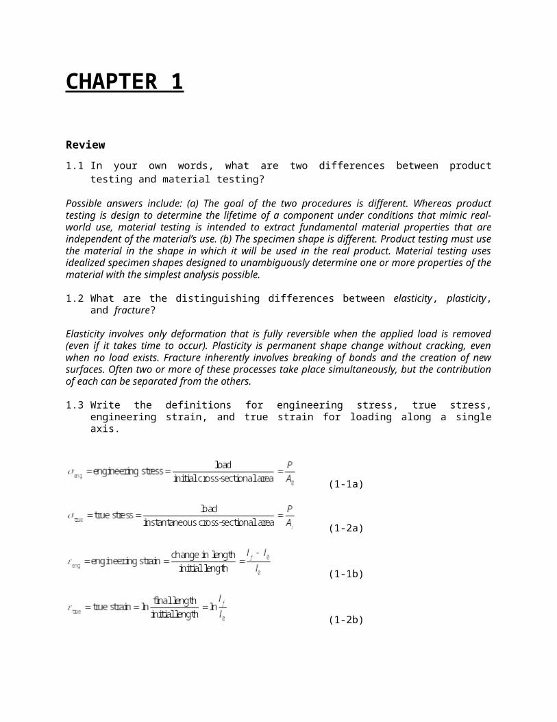
1.3 Write the definitions for engineering stress, true stress, engineering strain, and true strain for loading along a single axis.
(1-1a)
(1-2a)
(1-1b)
(1-2b)
1.4 Under what conditions is Eq. 1-4 valid? What makes it no longer useful if those conditions are not met?
(1-4)This expression is true when volume is conserved. However, it is only useful if the cross-sectional area is the same everyone on the test specimen. If this isn’t the case then the stress and strain will vary from one part of the specimen to another.
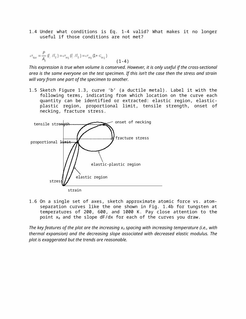
1.5 Sketch Figure 1.3, curve ‘b’ (a ductile metal). Label it with the following terms, indicating from which location on the curve each quantity can be identified or extracted: elastic region, elastic-plastic region, proportional limit, tensile strength, onset of necking, fracture stress.
strain
stress
fracture stress
elastic region
elastic-plastic region
proportional limit
tensile strength onset of necking
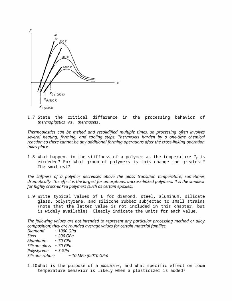
1.6 On a single set of axes, sketch approximate atomic force vs. atom-separation curves like the one shown in Fig. 1.4b for tungsten at temperatures of 200, 600, and 1000 K. Pay close attention to the point x0 and the slope dF/dx for each of the curves you draw.
The key features of the plot are the increasing x0 spacing with increasing temperature (i.e., with thermal expansion) and the decreasing slope associated with decreased elastic modulus. The plot is exaggerated but the trends are reasonable.
F
x
x0 (1000 K)
x0 (600 K)
x0 (200 K)
dF
dx200 K
600 K
1000 K
1.7 State the critical difference in the processing behavior of thermoplastics vs. thermosets.
Thermoplastics can be melted and resolidified multiple times, so processing often involves several heating, forming, and cooling steps. Thermosets harden by a one-time chemical reaction so there cannot be any additional forming operations after the cross-linking operation takes place.
1.8 What happens to the stiffness of a polymer as the temperature Tg is exceeded? For what group of polymers is this change the greatest? The smallest?
The stiffness of a polymer decreases above the glass transition temperature, sometimes dramatically. The effect is the largest for amorphous, uncross-linked polymers. It is the smallest for highly cross-linked polymers (such as certain epoxies).
1.9 Write typical values of E for diamond, steel, aluminum, silicate glass, polystyrene, and silicone rubber subjected to small strains (note that the latter value is not included in this chapter, but is widely available). Clearly indicate the units for each value.
The following values are not intended to represent any particular processing method or alloy composition; they are rounded average values for certain material families.Diamond ~ 1000 GPaSteel ~ 200 GPaAluminum ~ 70 GPaSilicate glass ~ 70 GPaPolystyrene ~ 3 GPaSilicone rubber ~ 10 MPa (0.010 GPa)
1.10 What is the purpose of a plasticizer, and what specific effect on room temperature behavior is likely when a plasticizer is added?
A plasticizer is added to a polymer to break up the molecular interactions, allowing more chain mobility than would otherwise be possible for that particular polymer at the temperature of interest. At room
temperature, therefore, the polymer is more likely to have a low elastic modulus (i.e., a ordinarily-hard polymer may become flexible).
1.11 Identify a minimum of two structural characteristics and two mechanical characteristics that set elastomers apart from other classes of materials (including other polymers).
Elastomers are amorphous and moderately cross-linked. They tend to display significant changes in stiffness as their use temperate exceeds Tg, but they do not melt at even higher temperature.
1.12 Define what is meant by uniaxial, biaxial and triaxial loading.
Uniaxial loading occurs along a single direction, biaxial along two directions, and triaxial along three. Note that there may be multiaxial strains even when the loading is restricted to one or two directions.
1.13 State one advantage and disadvantage of compression testing.
An advantage may be to avoid failure due to tensile cracking at low loads (as in the case for ceramics and glasses), and therefore to allow exploration of degrees of plasticity impossible to achieve under tensile loading. One disadvantage would be the difficulty in achieving ideal friction-free conditions between the specimen and the loading platen.
1.14 Is buckling failure initiated by an elastic, plastic, or cracking process? Explain.
Buckling failure is initially an elastic process in which the member deflects in a direction perpendicular to the loading axis. This failure may then be followed by plasticity or fracture, but these processes are not inherent in buckling.
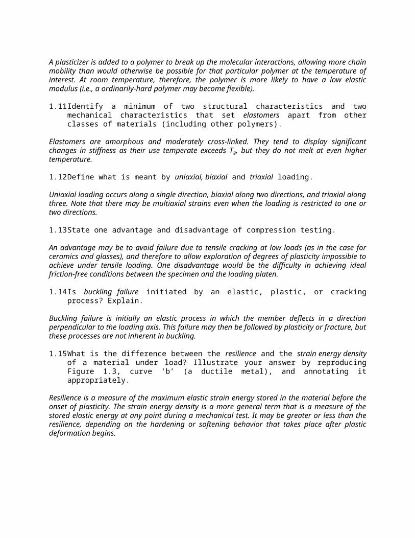
1.15 What is the difference between the resilience and the strain energy density of a material under load? Illustrate your answer by reproducing Figure 1.3, curve ‘b’ (a ductile metal), and annotating it appropriately.
Resilience is a measure of the maximum elastic strain energy stored in the material before the onset of plasticity. The strain energy density is a more general term that is a measure of the stored elastic energy at any point during a mechanical test. It may be greater or less than the resilience, depending on the hardening or softening behavior that takes place after plastic deformation begins.
strain
stress
strain energy density at thepoint of necking
resilience
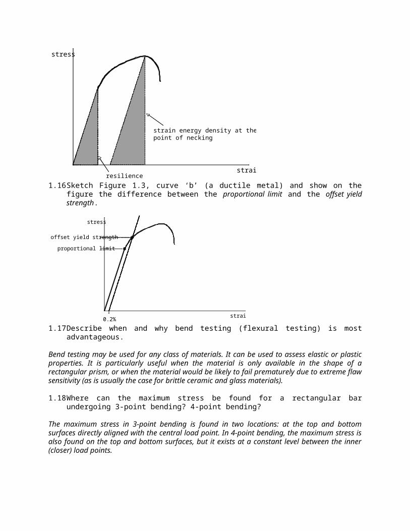
1.16 Sketch Figure 1.3, curve ‘b’ (a ductile metal) and show on the figure the difference between the proportional limit and the offset yield strength.
strain
stress
proportional limit
offset yield strength
0.2%
1.17 Describe when and why bend testing (flexural testing) is most advantageous.
Bend testing may be used for any class of materials. It can be used to assess elastic or plastic properties. It is particularly useful when the material is only available in the shape of a rectangular prism, or when the material would be likely to fail prematurely due to extreme flaw sensitivity (as is usually the case for brittle ceramic and glass materials).
1.18 Where can the maximum stress be found for a rectangular bar undergoing 3-point bending? 4-point bending?
The maximum stress in 3-point bending is found in two locations: at the top and bottom surfaces directly aligned with the central load point. In 4-point bending, the maximum stress is also found on the top and bottom surfaces, but it exists at a constant level between the inner (closer) load points.
1.19 Write the basic isotropic form of Hooke’s law relating stress and strain for uniaxial tension/compression loading and shear loading. Define all quantities.
Linear elastic uniaxial tension/compression is described by , where is stress, is Young’s modulus, and is strain. An analogous form exists for shear loading, for which = G. In this expression, is the shear stress, G is the shear modulus, and is the shear strain.
1.20 Why do we define engineering and true stresses for tension/compression loading but not for shear loading?
In tension and compression the cross-sectional area bearing the load changes during deformation, so it is often necessary to account for this change. In shear loading there is distortion of the material but the area over which the force is distributed does not change, so there is no need for a true stress definition.
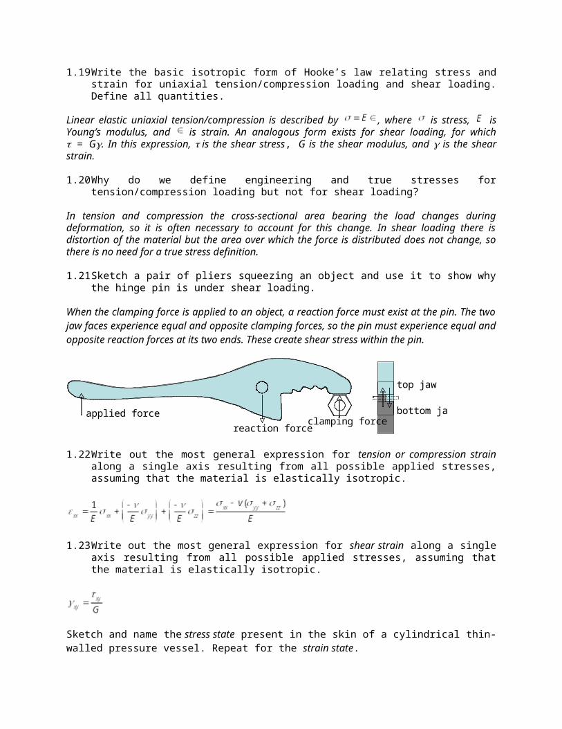
1.21 Sketch a pair of pliers squeezing an object and use it to show why the hinge pin is under shear loading.
When the clamping force is applied to an object, a reaction force must exist at the pin. The two jaw faces experience equal and opposite clamping forces, so the pin must experience equal and opposite reaction forces at its two ends. These create shear stress within the pin.
applied forceclamping force
reaction force
top jaw
bottom jaw
1.22 Write out the most general expression for tension or compression strain along a single axis resulting from all possible applied stresses, assuming that the material is elastically isotropic.
1.23 Write out the most general expression for shear strain along a single axis resulting from all possible applied stresses, assuming that the material is elastically isotropic.
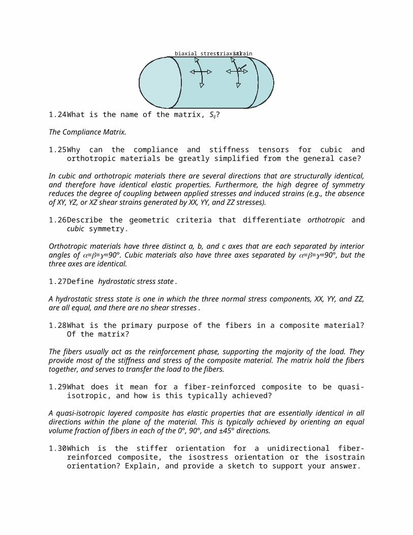
Sketch and name the stress state present in the skin of a cylindrical thin-walled pressure vessel. Repeat for the strain state.
triaxial strainbiaxial stress
1.24 What is the name of the matrix, Sij?
The Compliance Matrix.
1.25 Why can the compliance and stiffness tensors for cubic and orthotropic materials be greatly simplified from the general case?
In cubic and orthotropic materials there are several directions that are structurally identical, and therefore have identical elastic properties. Furthermore, the high degree of symmetry reduces the degree of coupling between applied stresses and induced strains (e.g., the absence of XY, YZ, or XZ shear strains generated by XX, YY, and ZZ stresses).
1.26 Describe the geometric criteria that differentiate orthotropic and cubic symmetry.
Orthotropic materials have three distinct a, b, and c axes that are each separated by interior angles of ===90°. Cubic materials also have three axes separated by ===90°, but the three axes are identical.
1.27 Define hydrostatic stress state.
A hydrostatic stress state is one in which the three normal stress components, XX, YY, and ZZ, are all equal, and there are no shear stresses.
1.28 What is the primary purpose of the fibers in a composite material? Of the matrix?
The fibers usually act as the reinforcement phase, supporting the majority of the load. They provide most of the stiffness and stress of the composite material. The matrix hold the fibers together, and serves to transfer the load to the fibers.
1.29 What does it mean for a fiber-reinforced composite to be quasi-isotropic, and how is this typically achieved?
A quasi-isotropic layered composite has elastic properties that are essentially identical in all directions within the plane of the material. This is typically achieved by orienting an equal volume fraction of fibers in each of the 0°, 90°, and ±45° directions.
1.30 Which is the stiffer orientation for a unidirectional fiber-reinforced composite, the isostress orientation or the isostrain orientation? Explain, and provide a sketch to support your answer.
The stiffer direction is the isostrain orientation, in which the fibers and the matrix must strain by equal amounts. In this orientation, the stiffer fibers typically bear the majority of the load, and so the composite stiffness is maximized for a given volume fraction of fibers. In the isostress orientation, the compliant matrix is free to strain to a larger degree than the stiff fibers, so the overall stiffness is lower.
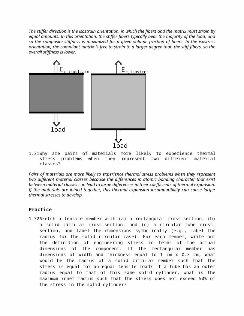
Ec, isostrain Ec, isostress
load
load1.31 Why are pairs of materials more likely to experience thermal stress problems when they represent
two different material classes?
Pairs of materials are more likely to experience thermal stress problems when they represent two different material classes because the differences in atomic bonding character that exist between material classes can lead to large differences in their coefficients of thermal expansion. If the materials are joined together, this thermal expansion incompatibility can cause larger thermal stresses to develop.
Practice
1.32 Sketch a tensile member with (a) a rectangular cross-section, (b) a solid circular cross-section, and (c) a circular tube cross-section, and label the dimensions symbolically (e.g., label the radius for the solid circular case). For each member, write out the definition of engineering stress in terms of the actual dimensions of the component. If the rectangular member has dimensions of width and thickness equal to 1 cm x 0.3 cm, what would be the radius of a solid circular member such that the stress is equal for an equal tensile load? If a tube has an outer radius equal to that of this same solid cylinder, what is the maximum inner radius such that the stress does not exceed 50% of the stress in the solid cylinder?
w
t
r
r1
r2
eng
F
A
F
tw
eng
F
A
F
r 2
eng
F
A
F
r12 r
22
F
r12 r
22
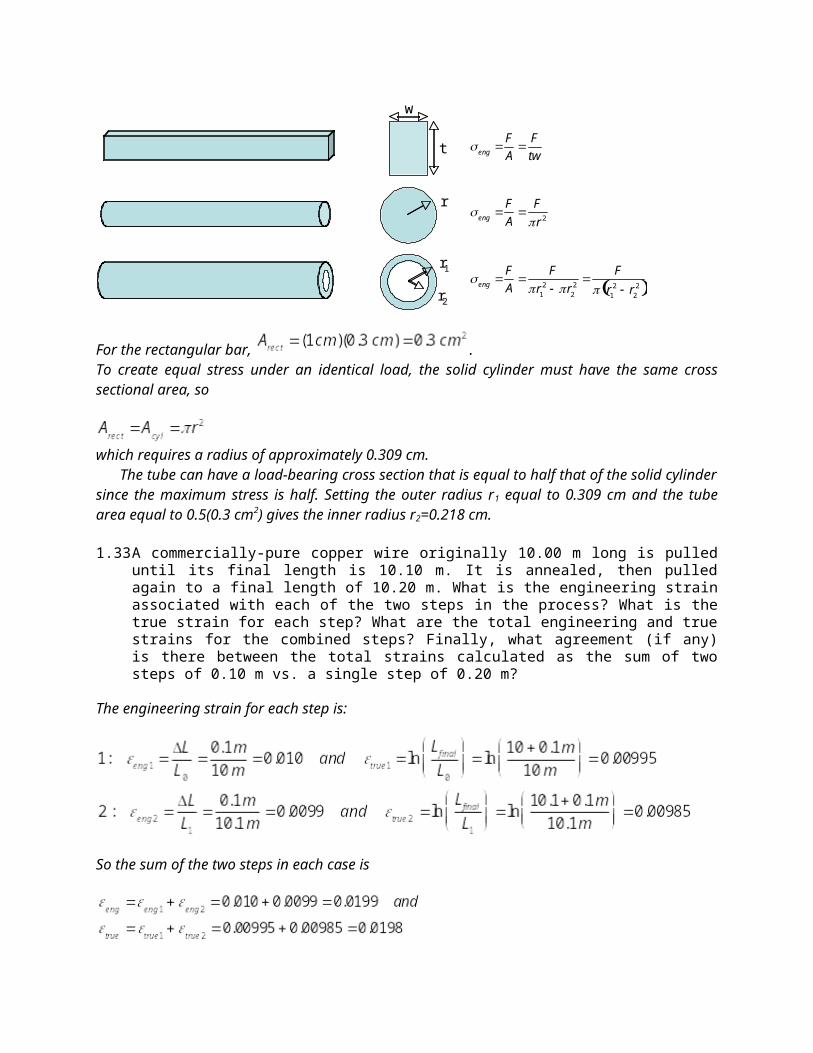
For the rectangular bar, .To create equal stress under an identical load, the solid cylinder must have the same cross sectional area, so
which requires a radius of approximately 0.309 cm.The tube can have a load-bearing cross section that is equal to half that of the solid cylinder since the
maximum stress is half. Setting the outer radius r1 equal to 0.309 cm and the tube area equal to 0.5(0.3 cm2) gives the inner radius r2=0.218 cm.
1.33 A commercially-pure copper wire originally 10.00 m long is pulled until its final length is 10.10 m. It is annealed, then pulled again to a final length of 10.20 m. What is the engineering strain associated with each of the two steps in the process? What is the true strain for each step? What are the total engineering and true strains for the combined steps? Finally, what agreement (if any) is there between the total strains calculated as the sum of two steps of 0.10 m vs. a single step of 0.20 m?
The engineering strain for each step is:
So the sum of the two steps in each case is
Calculating the total strain as if the elongation were performed in a single step:
So, it can be seen that the sum of the individual engineering strains does not agree with the strain calculated for a single elongation step of 0.20 m, whereas the total true strains is the same regardless of whether the 0.20 m elongation is applied in one increment or two.
1.34 A 3-mm-long gold alloy wire intended to electrically bond a computer chip to its package has an initial diameter of 30 µm. During testing, it is pulled axially with a load of 15 grams-force. If the wire diameter decreases uniformly to 29 µm, compute the following: (a) The final length of the wire.(b) The true stress and true strain at this load.(c) The engineering stress and strain at this load.
The final length of the wire is
The true stress and true strain are
The engineering stress and engineering strain are
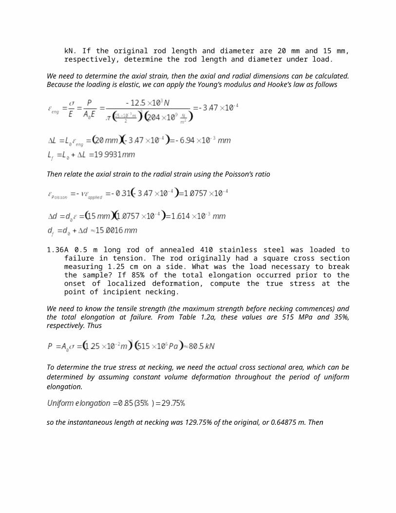
1.35 A cylindrical rod of Ni 200 alloy has the following properties: E = 204 GPa, = 0.31. It is loaded elastically in compression at 12.5 kN. If the original rod length and diameter are 20 mm and 15 mm, respectively, determine the rod length and diameter under load.
We need to determine the axial strain, then the axial and radial dimensions can be calculated. Because the loading is elastic, we can apply the Young’s modulus and Hooke’s law as follows
Then relate the axial strain to the radial strain using the Poisson’s ratio
1.36 A 0.5 m long rod of annealed 410 stainless steel was loaded to failure in tension. The rod originally had a square cross section measuring 1.25 cm on a side. What was the load necessary to break the sample? If 85% of the total elongation occurred prior to the onset of localized deformation, compute the true stress at the point of incipient necking.
We need to know the tensile strength (the maximum strength before necking commences) and the total elongation at failure. From Table 1.2a, these values are 515 MPa and 35%, respectively. Thus
To determine the true stress at necking, we need the actual cross sectional area, which can be determined by assuming constant volume deformation throughout the period of uniform elongation.
so the instantaneous length at necking was 129.75% of the original, or 0.64875 m. Then
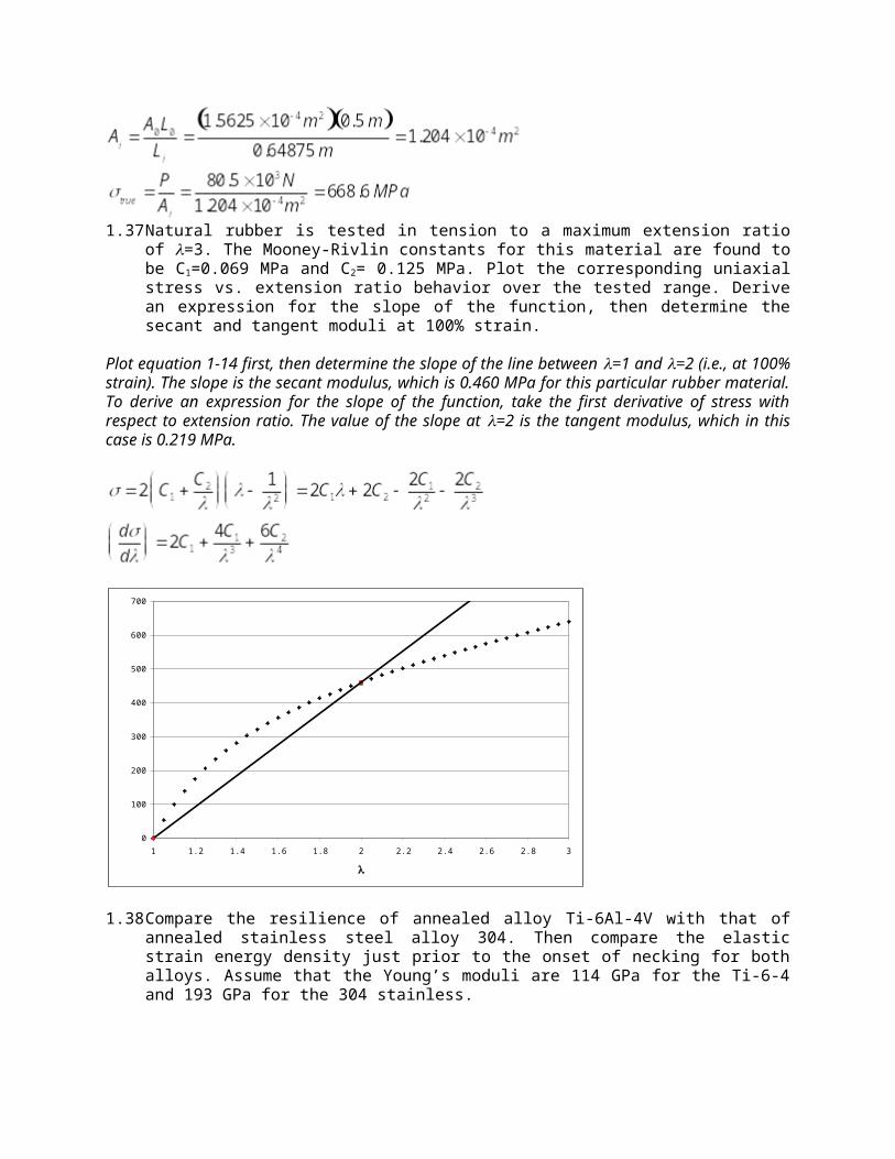
1.37 Natural rubber is tested in tension to a maximum extension ratio of =3. The Mooney-Rivlin constants for this material are found to be C1=0.069 MPa and C2= 0.125 MPa. Plot the corresponding uniaxial stress vs. extension ratio behavior over the tested range. Derive an expression for the slope of the function, then determine the secant and tangent moduli at 100% strain.
Plot equation 1-14 first, then determine the slope of the line between =1 and =2 (i.e., at 100% strain). The slope is the secant modulus, which is 0.460 MPa for this particular rubber material. To derive an expression for the slope of the function, take the first derivative of stress with respect to extension ratio. The value of the slope at =2 is the tangent modulus, which in this case is 0.219 MPa.
0
100
200
300
400
500
600
700
1 1.2 1.4 1.6 1.8 2 2.2 2.4 2.6 2.8 3
Str
ess (
kPa)
1.38 Compare the resilience of annealed alloy Ti-6Al-4V with that of annealed stainless steel alloy 304. Then compare the elastic strain energy density just prior to the onset of necking for both alloys. Assume that the Young’s moduli are 114 GPa for the Ti-6-4 and 193 GPa for the 304 stainless.
Resiliance is the area under the stress-strain curve at the proportional limit, whereas the elastic strain energy density at necking is determined from the elastic strain that exists at that point. From Eq. 1-19
We need the yield strength values from Table 1.2a: for annealed Ti-6Al-4V it is 925 MPa and for annealed 304 stainless it is 240 MPa. From these values, we see that the resilience of the Ti-6-4 is 3.75 MN/m2 (or MJ/m3). The resilience of the 304 stainless is 0.149 MN/m2 (or MJ/m3). The elastic strain energy density at necking is calculated the same way, but with the tensile strength values: 995 and 565 MPa, respectively, for the Ti-6-4 and the 304 stainless, respectively. The corresponding strain energy densities are 4.34 and 0.827 MN/m2 (or MJ/m3). Perhaps surprisingly, even though the stainless steel is much stiffer than the Ti alloy, high yield and tensile strength values make the Ti alloy the better material for elastic energy storage (at least when both are in the annealed state).
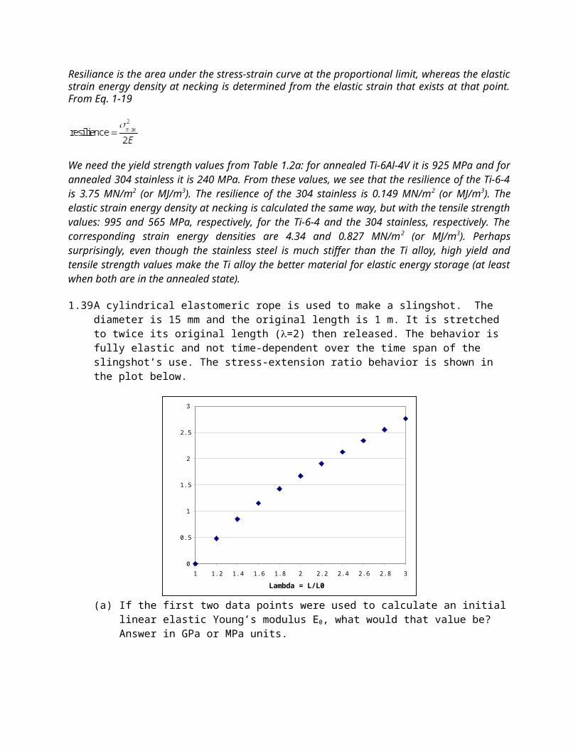
1.39 A cylindrical elastomeric rope is used to make a slingshot. The diameter is 15 mm and the original length is 1 m. It is stretched to twice its original length (=2) then released. The behavior is fully elastic and not time-dependent over the time span of the slingshot’s use. The stress-extension ratio behavior is shown in the plot below.
0
0.5
1
1.5
2
2.5
3
1 1.2 1.4 1.6 1.8 2 2.2 2.4 2.6 2.8 3
Lambda = L/L0
Str
ess (
N/m
m^
2)
(a) If the first two data points were used to calculate an initial linear elastic Young’s modulus E0, what would that value be? Answer in GPa or MPa units.
Take the slope of a line passing through the first two data points: E0=(0.5-0)/(1.2-1)=2.5 N/mm2, which converts to 2.5 N/10-6 m2 or simply 2.5 MPa.
(b) Based on the plot above, what is the diameter of the rope at =2? Noting that this is a large strain, state and justify any assumption you must make to answer this question.
When =2, the length is twice the original. Assume that volume is constant during elastic deformation (i.e., =0.5), a reasonable decision for rubber materials, so that A0l0= Aflf. Then
Note that if you use the standard linear relationship between axial strain, radial strain, and Poisson’s ratio you will get a significantly smaller final diameter. The linear expression is only accurate for small strains, whereas in this case =2, so =1.00 (definitely a large strain).
(c) For a rubber material, one possible non-linear relationship relating stress and extension ratio is given by Eq 1-13. Assume that this is a reasonable expression for the behavior depicted above, and calculate the expected stored energy density at = 2. Be sure to report units.
Eq. 1-13 is and the stored energy density is given by the area under the stress-strain (or stress-extension ratio) plot. Determine this by integrating Eq. 1-13 from =1 to =2.
1.40 A rectangular plate 100 mm long, 10 mm wide and 3 mm thick is formed from fused silica. It is tested in 3-point bending until it fails with a modulus of rupture of 110 MPa at a load of 66 N. Assume the central load point is on the top of the beam.(a) How far apart must have been the lower supports?
Eq. 1-24 shows that the rupture strength can be related to the specimen dimensions and the rupture load as
so we can rearrange the expression to solve for L, the support span:
(b) What was the maximum stress (magnitude and sign) on the top side of the beam halfway between the central load point and the left-hand lower load point?
If the top side of the beam is associated with the single load point, it will be the compressive side. Stress on the compressive side is negative in sign, is a maximum on the outer surface, and changes linearly from the center load point to the outer load point. Thus the stress halfway along this surface must have been -110 MPa/2 = -55 MPa.
(c) What was the stress (magnitude and sign) directly beneath the central load point exactly 1.5 mm from the top surface?
The plane located parallel to the top and bottom surfaces at a distance of 1.5 mm from the top is the central plane of the plate. It is the neutral axis for which there is no length change during bending, so the stress will be zero.
(d) If the same plate was tested in pure tension would the stress at failure probably be higher or lower than measured by three point bending? Why?
In tension a larger fraction of the surface is exposed to the maximum stress, so it is statistically more likely that a fatal flaw will be subjected to sufficiently high stress to cause failure. One would therefore expect that the stress at failure would probably be lower in tension than in three point bending.
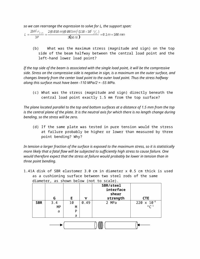
1.41 A disk of SBR elastomer 3.0 cm in diameter x 0.5 cm thick is used as a cushioning surface between two steel rods of the same diameter, as shown below (not to scale).
G E SBR/steel interface
shear strength CTESBR 3.4 MPa 10 MPa 0.49 2 MPa 220 x 10-6 °C-1
(a) If the rods are brought together with an axial force of 100 N such that the SBR is compressed elastically between them, what is the thickness of the SBR under load?
Then, using the definition of strain, we can say that
(b) Under the same conditions as part ‘a’, what is the greatest possible diameter of the SBR under load?
Use Poisson’s Ratio to relate axial strain to radial strain. This will give a maximum diameter because the SBR disk is constrained at its ends by the attachment to the rods.
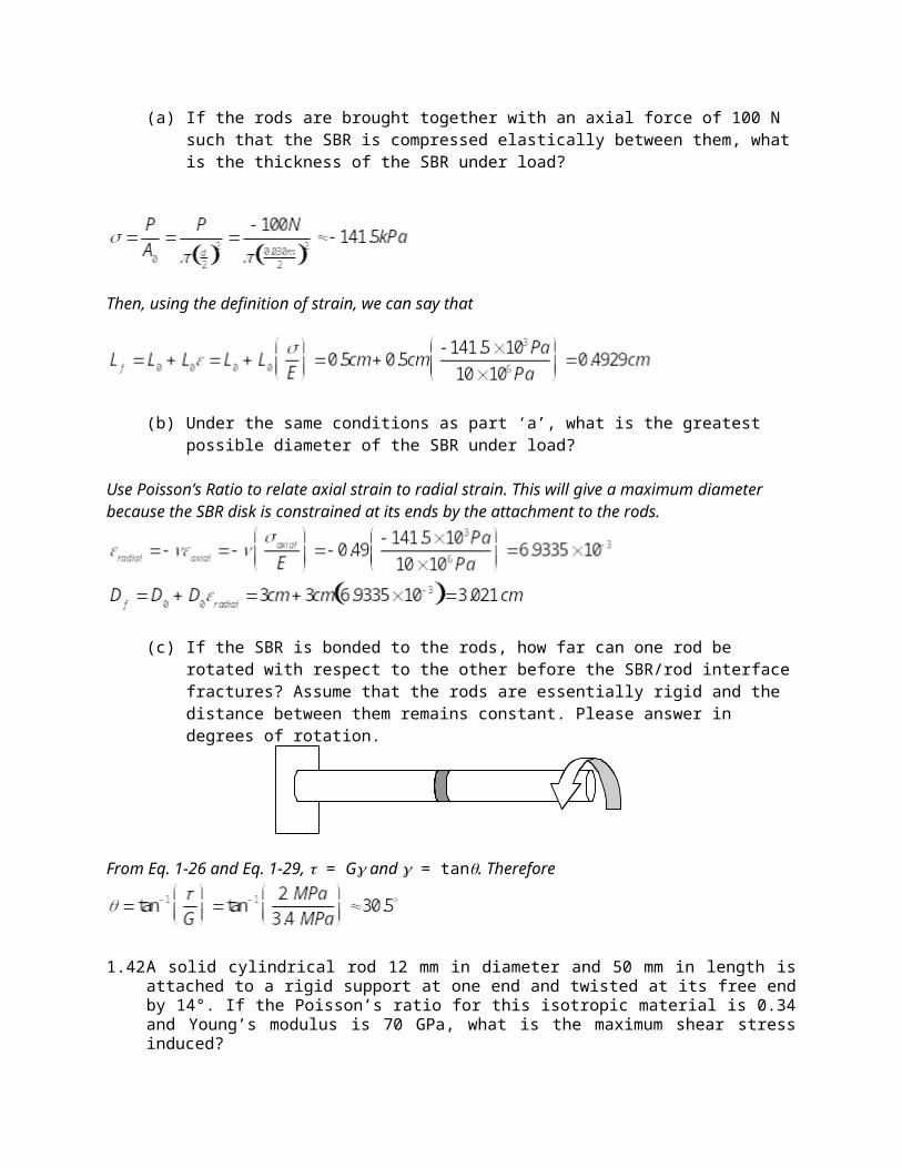
(c) If the SBR is bonded to the rods, how far can one rod be rotated with respect to the other before the SBR/rod interface fractures? Assume that the rods are essentially rigid and the distance between them remains constant. Please answer in degrees of rotation.
From Eq. 1-26 and Eq. 1-29, = G and = tan. Therefore
1.42 A solid cylindrical rod 12 mm in diameter and 50 mm in length is attached to a rigid support at one end and twisted at its free end by 14°. If the Poisson’s ratio for this isotropic material is 0.34 and Young’s modulus is 70 GPa, what is the maximum shear stress induced?
From Eq. 1-26 and Eq. 1-33, = G and max= D/2L. We need G, which is available from the other two elastic constants because the material is elastically isotropic. Together we have
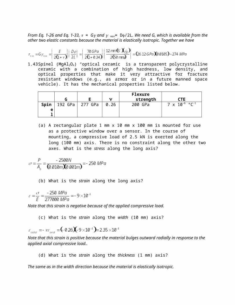
1.43 Spinel (MgAl2O4) “optical ceramic” is a transparent polycrystalline ceramic with a combination of high hardness, low density, and optical properties that make it very attractive for fracture resistant windows (e.g., as armor or in a future manned space vehicle). It has the mechanical properties listed below.
G E Flexure strength CTESpinel 192 GPa 277 GPa 0.26 200 GPa 7 x 10⁻⁶ °C-1
(a) A rectangular plate 1 mm x 10 mm x 100 mm is mounted for use as a protective window over a sensor. In the course of mounting, a compressive load of 2.5 kN is exerted along the long (100 mm) axis. There is no constraint along the other two axes. What is the stress along the long axis?
(b) What is the strain along the long axis?
Note that this strain is negative because of the applied compressive load.
(c) What is the strain along the width (10 mm) axis?
Note that this strain is positive because the material bulges outward radially in response to the applied axial compressive load..
(d) What is the strain along the thickness (1 mm) axis?
The same as in the width direction because the material is elastically isotropic.
(e) Now the plate is rigidly constrained along its width (the 10 mm axis). This has the consequence that the plate cannot change length along that axis, although it is still free to change thickness dimension. The same 2.5 kN load is exerted along the long axis. Now what is the strain along the long axis?
Set up the generalized Hooke’s Law equations for the two axes that we care about: the direction of the applied load (arbitrarily call it direction 3) and the constrained direction (direction 2). The material is free to expand or contract in direction 1 (thickness) so the stress along that axis must be zero (i.e., this is a plane stress condition). Beginning with direction 2:
then moving on to direction 3:
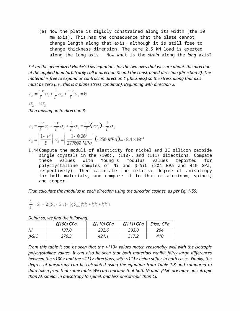
1.44 Compute the moduli of elasticity for nickel and 3C silicon carbide single crystals in the 〈100〉, 〈110〉, and 〈111〉 directions. Compare these values with Young’s modulus values reported for polycrystalline samples of Ni and -SiC (204 GPa and 410 GPa, respectively). Then calculate the relative degree of anisotropy for both materials, and compare it to that of aluminum, spinel, and copper.
First, calculate the modulus in each direction using the direction cosines, as per Eq. 1-55:
Doing so, we find the following:E(100) GPa E(110) GPa E(111) GPa E(iso) GPa
Ni 137.0 232.6 303.0 204-SiC 270.3 421.1 517.2 410
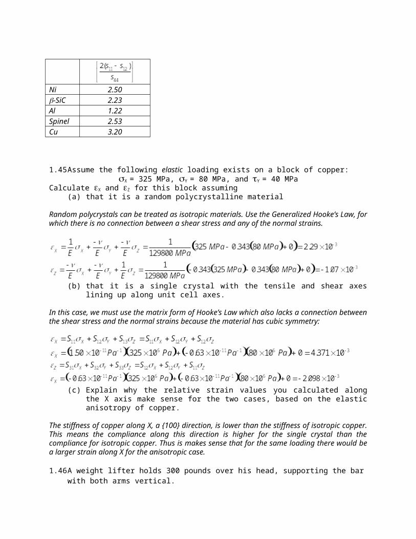
From this table it can be seen that the <110> values match reasonably well with the isotropic polycrystalline values. It can also be seen that both materials exhibit fairly large differences between the <100> and the <111> directions, with <111> being stiffer in both cases. Finally, the degree of anisotropy can be calculated using the equation from Table 1.8 and compared to data taken from that same table. We can conclude that both Ni and -SiC are more anisotropic than Al, similar in anisotropy to spinel, and less anisotropic than Cu.
Ni 2.50-SiC 2.23Al 1.22Spinel 2.53Cu 3.20
1.45 Assume the following elastic loading exists on a block of copper: X = 325 MPa, Y = 80 MPa, and Y = 40 MPa
Calculate X and Z for this block assuming(a) that it is a random polycrystalline material
Random polycrystals can be treated as isotropic materials. Use the Generalized Hooke’s Law, for which there is no connection between a shear stress and any of the normal strains.
(b) that it is a single crystal with the tensile and shear axes lining up along unit cell axes.
In this case, we must use the matrix form of Hooke’s Law which also lacks a connection between the shear stress and the normal strains because the material has cubic symmetry:
(c) Explain why the relative strain values you calculated along the X axis make sense for the two cases, based on the elastic anisotropy of copper.
The stiffness of copper along X, a {100} direction, is lower than the stiffness of isotropic copper. This means the compliance along this direction is higher for the single crystal than the compliance for isotropic copper. Thus is makes sense that for the same loading there would be a larger strain along X for the anisotropic case.
1.46 A weight lifter holds 300 pounds over his head, supporting the bar with both arms vertical. (a) What is the stress in each humerus (upper arm bone), assuming that it can be approximated as a
solid cylindrical rod with cross sectional area of 1.05 in2? Use SI units.
(b) What are the corresponding axial and radial strains?
Consulting Fig. 1.15, direction 3 is axial and direction 1 is radial. Then using values from Table 1.5 and equation 1-49, we find that
(c) If the humerus is 9 inches long, what are the length and diameter changes associated with this massive load? Please give this answer in inches.
1.47 A thin-walled pressure vessel is subjected to internal pressure such that a hoop stress of 100 MPa develops. Imagine that the vessel is made of an orthotropic continuous fiber composite with most of the fibers running around the circumference. The elastic constants for this material are given below, with direction 3 around the circumference, direction 2 along the length, and direction 1 through the thickness. What is the strain in the hoop direction?
11 22 33 44 55 66 12 13 23S (GPa-1) 0.08 0.075 0.05 0.161 0.178 0.221 0.031 0.019 0.018
C (GPa) 18.0 20.2 27.6 6.23 5.61 4.52 9.98 10.1 10.7
There are two stresses present, one in the circumferential direction (3) and one in the longitudinal direction (2). The longitudinal stress will be half that of the circumferential stress. Solve for strain along axis 3, using the orthotropic version of the compliance matrix. In order to do so, we must recognize that 31=13 and 32=23 because of symmetry.
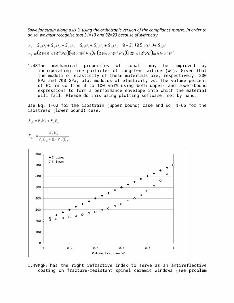
1.48 The mechanical properties of cobalt may be improved by incorporating fine particles of tungsten carbide (WC). Given that the moduli of elasticity of these materials are, respectively, 200 GPa and 700 GPa, plot modulus of elasticity vs. the volume percent of WC in Co from 0 to 100 vol% using both upper- and lower-bound expressions to form a performance envelope into which the material will fall. Please do this using plotting software, not by hand.
Use Eq. 1-62 for the isostrain (upper bound) case and Eq. 1-66 for the isostress (lower bound) case.
0
100
200
300
400
500
600
700
800
0 0.2 0.4 0.6 0.8 1
Volume fraction WC
E (
GPa)
E upper
E lower
1.49 MgF2 has the right refractive index to serve as an antireflective coating on fracture-resistant spinel ceramic windows (see problem above). Assume that the MgF2 can be deposited as a polycrystalline thin film on thick spinel. MgF2 mechanical properties are listed below.
G E CTEMgF2 54.5 GPa 138.5 GPa 0.27 10 x 10-6 °C-1
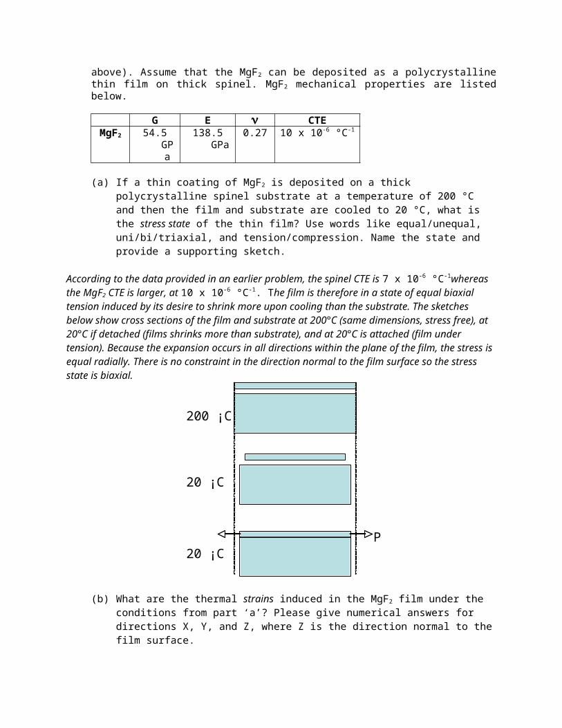
(a) If a thin coating of MgF2 is deposited on a thick polycrystalline spinel substrate at a temperature of 200 °C and then the film and substrate are cooled to 20 °C, what is the stress state of the thin film? Use words like equal/unequal, uni/bi/triaxial, and tension/compression. Name the state and provide a supporting sketch.
According to the data provided in an earlier problem, the spinel CTE is 7 x 10⁻⁶ °C-1whereas the MgF2 CTE is larger, at 10 x 10-6 °C-1. The film is therefore in a state of equal biaxial tension induced by its desire to shrink more upon cooling than the substrate. The sketches below show cross sections of the film and substrate at 200°C (same dimensions, stress free), at 20°C if detached (films shrinks more than substrate), and at 20°C is attached (film under tension). Because the expansion occurs in all directions within the plane of the film, the stress is equal radially. There is no constraint in the direction normal to the film surface so the stress state is biaxial.
200 ¡C
20 ¡C
20 ¡CP
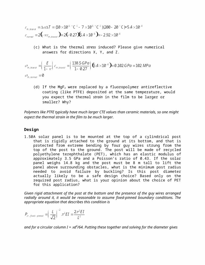
(b) What are the thermal strains induced in the MgF2 film under the conditions from part ‘a’? Please give numerical answers for directions X, Y, and Z, where Z is the direction normal to the film surface.
(c) What is the thermal stress induced? Please give numerical answers for directions X, Y, and Z.
(d) If the MgF2 were replaced by a fluoropolymer antireflective coating (like PTFE) deposited at the same temperature, would you expect the thermal strain in the film to be larger or smaller? Why?
Polymers like PTFE typically have much larger CTE values than ceramic materials, so one might expect the thermal strain in the film to be much larger.
Design
1.50 A solar panel is to be mounted at the top of a cylindrical post that is rigidly attached to the ground at its bottom, and that is protected from extreme bending by four guy wires strung from the top of the post to the ground. The post will be made of recycled polyethylene terephthalate (PET), which has an elastic modulus of approximately 3.5 GPa and a Poisson’s ratio of 0.43. If the solar panel weighs 14.8 kg and the post must be 8 m tall to lift the panel above surrounding obstacles, what is the minimum post radius needed to avoid failure by buckling? Is this post diameter actually likely
to be a safe design choice? Based only on the required post radius, what is your opinion about the choice of PET for this application?
Given rigid attachment of the post at the bottom and the presence of the guy wires arranged radially around it, it would be reasonable to assume fixed-pinned boundary conditions. The appropriate equation that describes this condition is
and for a circular column I = d4/64. Putting these together and solving for the diameter gives
This would not be a safe radius to use because it has no safety factor to cover uncertainties and deviations from ideal loading. It would be better to add a safety factor of 2-3x. In this case, the radius would have to be 40-60 cm. Even without the safety factor, the radius is very large (more like a tree trunk than a slender column). Perhaps a stiffer material would be a better choice for this particular load and height requirement.
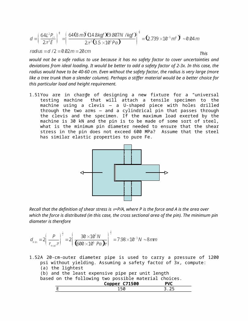
1.51 You are in charge of designing a new fixture for a “universal testing machine” that will attach a tensile specimen to the machine using a clevis — a U-shaped piece with holes drilled through the two arms — and a cylindrical pin that passes through the clevis and the specimen. If the maximum load exerted by the machine is 30 kN and the pin is to be made of some sort of steel, what is the minimum pin diameter needed to ensure that the shear stress in the pin does not exceed 600 MPa? Assume that the steel has similar elastic properties to pure Fe.
Recall that the definition of shear stress is =P/A, where P is the force and A is the area over which the force is distributed (in this case, the cross sectional area of the pin). The minimum pin diameter is therefore
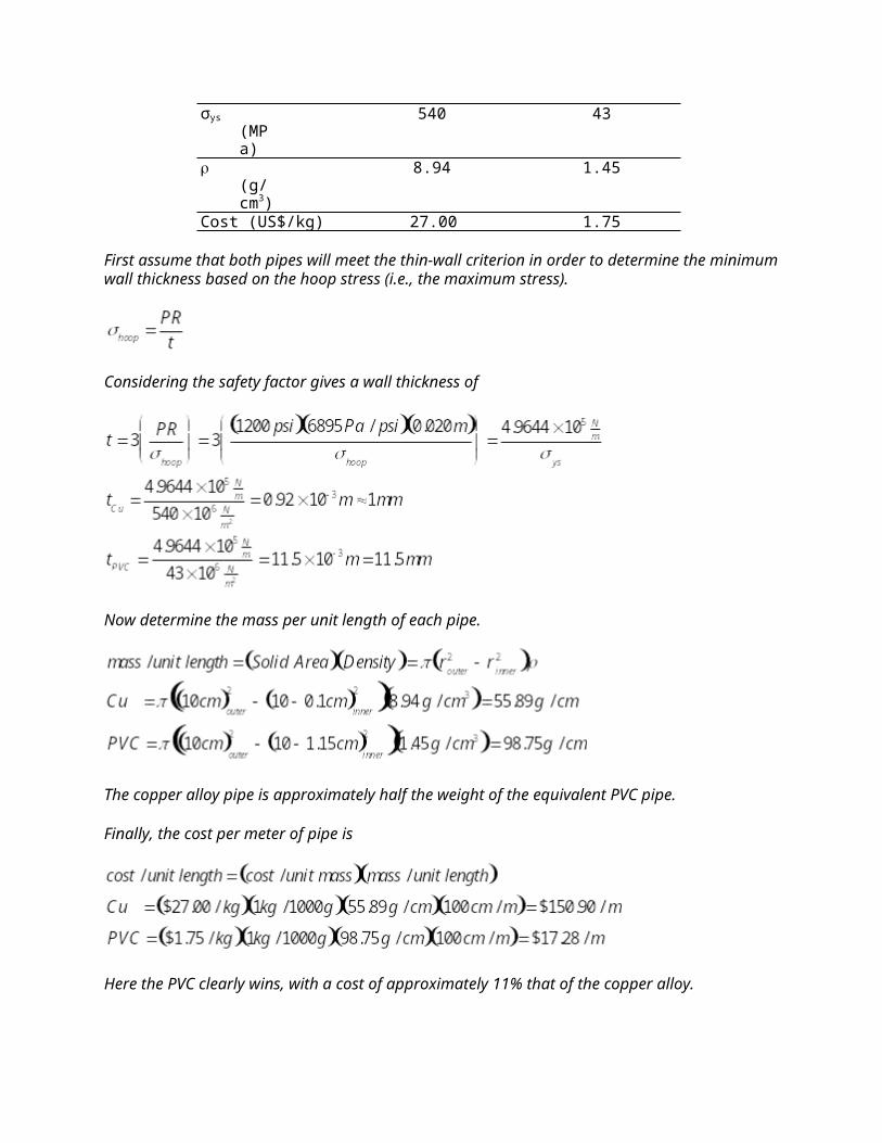
1.52 A 20-cm-outer diameter pipe is used to carry a pressure of 1200 psi without yielding. Assuming a safety factor of 3x, compute:(a) the lightest(b) and the least expensive pipe per unit lengthbased on the following two possible material choices.
Copper C71500 PVCE 150 3.25σys (MPa) 540 43 (g/cm3) 8.94 1.45Cost (US$/kg) 27.00 1.75
First assume that both pipes will meet the thin-wall criterion in order to determine the minimum wall thickness based on the hoop stress (i.e., the maximum stress).
Considering the safety factor gives a wall thickness of
Now determine the mass per unit length of each pipe.
The copper alloy pipe is approximately half the weight of the equivalent PVC pipe.
Finally, the cost per meter of pipe is
Here the PVC clearly wins, with a cost of approximately 11% that of the copper alloy.
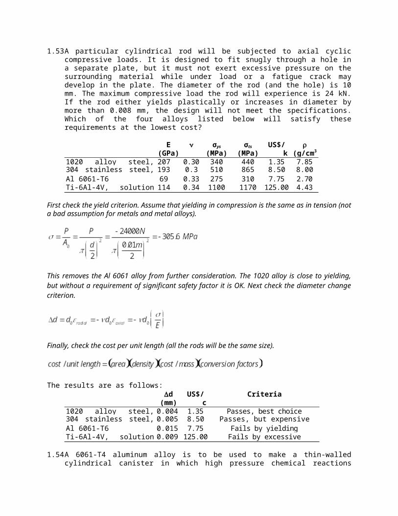
1.53 A particular cylindrical rod will be subjected to axial cyclic compressive loads. It is designed to fit snugly through a hole in a separate plate, but it must not exert excessive pressure on the surrounding material while under load or a fatigue crack may develop in the plate. The diameter of the rod (and the hole) is 10 mm. The maximum compressive load the rod will experience is 24 kN. If the rod either yields plastically or increases in diameter by more than 0.008 mm, the design will not meet the specifications. Which of the four alloys listed below will satisfy these requirements at the lowest cost?
E (GPa)
σys
(MPa)σts
(MPa)US$/kg
(g/cm3)1020 alloy steel, normalized 207 0.30 340 440 1.35 7.85304 stainless steel, cold worked 193 0.30 510 865 8.50 8.00Al 6061-T6 69 0.33 275 310 7.75 2.70Ti-6Al-4V, solution & aged 114 0.34 1100 1170 125.00 4.43
First check the yield criterion. Assume that yielding in compression is the same as in tension (not a bad assumption for metals and metal alloys).
This removes the Al 6061 alloy from further consideration. The 1020 alloy is close to yielding, but without a requirement of significant safety factor it is OK. Next check the diameter change criterion.
Finally, check the cost per unit length (all the rods will be the same size).
The results are as follows:d
(mm) US$/cm Criteria
1020 alloy steel, normalized 0.004 1.35 Passes, best choice304 stainless steel, cold worked 0.005 8.50 Passes, but expensiveAl 6061-T6 0.015 7.75 Fails by yieldingTi-6Al-4V, solution & aged 0.009 125.00 Fails by excessive diameter change
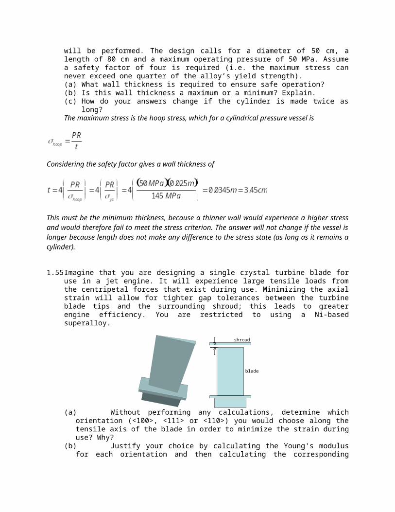
1.54 A 6061-T4 aluminum alloy is to be used to make a thin-walled cylindrical canister in which high pressure chemical reactions will be performed. The design calls for a diameter of 50 cm, a length of 80 cm and a maximum operating pressure of 50 MPa. Assume a safety factor of four is required (i.e. the maximum stress can never exceed one quarter of the alloy’s yield strength).(a) What wall thickness is required to ensure safe operation?(b) Is this wall thickness a maximum or a minimum? Explain. (c) How do your answers change if the cylinder is made twice as long?The maximum stress is the hoop stress, which for a cylindrical pressure vessel is
Considering the safety factor gives a wall thickness of
This must be the minimum thickness, because a thinner wall would experience a higher stress and would therefore fail to meet the stress criterion. The answer will not change if the vessel is longer because length does not make any difference to the stress state (as long as it remains a cylinder).
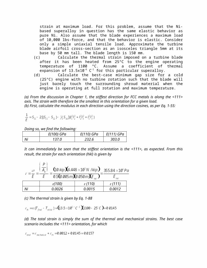
1.55 Imagine that you are designing a single crystal turbine blade for use in a jet engine. It will experience large tensile loads from the centripetal forces that exist during use. Minimizing the axial strain will allow for tighter gap tolerances between the turbine blade tips and the surrounding shroud; this leads to greater engine efficiency. You are restricted to using a Ni-based superalloy.
blade
shroud
(a) Without performing any calculations, determine which orientation (<100>, <111> or <110>) you would choose along the tensile axis of the blade in order to minimize the strain during use? Why?
(b) Justify your choice by calculating the Young's modulus for each orientation and then calculating the corresponding strain at maximum load. For this problem, assume that the Ni-based superalloy in question has the same elastic behavior as pure Ni. Also assume that the blade experiences a maximum load of 10,000 lbs-force, and that the behavior is elastic. Consider only a simple uniaxial tensile load. Approximate the turbine blade airfoil cross-section as an isosceles triangle 5mm at its base by 50 mm tall. The blade length is 150 mm.
(c) Calculate the thermal strain imposed on a turbine blade after it has been heated from 25°C to the engine operating temperature of 1100 °C. Assume a coefficient of thermal expansion of 13.5x10⁻⁶ C-1 for this particular superalloy.
(d) Calculate the best-case minimum gap size for a cold (25°C) engine with no turbine rotation such that the blade will just barely touch the surrounding shroud material when the engine is operating at full rotation and maximum temperature.
(a) From the discussion in Chapter 1, the stiffest direction for FCC metals is along the <111> axis. The strain with therefore be the smallest in this orientation for a given load.(b) First, calculate the modulus in each direction using the direction cosines, as per Eq. 1-55:
Doing so, we find the following:E(100) GPa E(110) GPa E(111) GPa
Ni 137.0 232.6 303.0
It can immediately be seen that the stiffest orientation is the <111>, as expected. From this result, the strain for each orientation (hkl) is given by
(100) (110) (111)Ni 0.0026 0.0015 0.0012
(c) The thermal strain is given by Eq. 1-88
(d) The total strain is simply the sum of the thermal and mechanical strains. The best case scenario includes the <111> orientation, for which
The minimum gap size prior to operation of the engine is equal to the expected change in blade length given by
Extend
1.56 Write a 1-2 page review of auxetic materials. Assume that you are writing a supplementary article for an introductory engineering text. Be sure to (1) define the term “auxetic material” and (2) explain what is unusual about the mechanical behavior of this class of materials. Include (3) a
picture (sketch, diagram, or photograph) of an auxetic material. Also (4) describe at least two products that could (or do) benefit from the auxetic behavior. Provide full references for all of your information.
Key points: An auxetic material is one that has a negative Poisson’s ratio, so it expands laterally when a
tensile strain is imposed axially. Not the same phenomenon as the medical term auxetic that has to do with cell expansion and
division. From the Greek auxētikos = increasing Examples of auxetic materials include “reentrant” foams, certain microporous polymers, and
zeolites Potential applications include filters and shock absorbing materials.
1.57 Select two thermoplastic materials from among those listed in Section 1.3.3.1. Using any resources available to you, determine a typical glass transition temperature, degree of crystallinity, and a common use for each of the polymer materials you selected. How does the use reflect the Tg value and the degree of crystallinity for each material?
Example: Thermoplastics polystyrene (PS) and high density polyethylene (HDPE) have Tg values of
approximately 100°C and -90 °C, respectively. PS is amorphous. As Tg>> room temperature for PS, it tends to be rigid and fairly stiff under
ambient use conditions. PS is used to make plastic cutlery and Petri dishes, two applications for which reasonable
stiffness is necessary for proper function. HDPE is partially crystalline. As Tg<< room temperature for HDPE, it tends to be fairly
compliant under ambient use conditions. However, because of its partial crystallinity there is a relatively small drop in stiffness associated with being above Tg, so it is much stiffer than typical elastomers (for example).
HDPE is used to make milk bottles and laundry detergent bottles, for which some flexibility is desirable but extreme flexibility would not be.
1.58 Write a 1-2 page review of the structure and elastic behavior of natural highly-elastic materials. Assume that you are writing a supplementary article for an introductory engineering text. Choose two or more materials for comparison: dragline spider silk, non-dragline spider silk, collagen, elastin, mussel byssal threads, and resilin. In your review, be sure to (1) identify the natural use for each of the materials you selected, and (2) explain how the particular properties of the materials match their intended uses in nature. Mention (3) approximately how much of the behavior is purely elastic (instantaneous recovery with no energy loss) and how much is viscoelastic (time-dependent recovery with some energy loss). Include (4) a picture (sketch, diagram, or photograph) or a plot that adds to the reader’s understanding of the topic. Strength is also interesting and certainly worth mentioning, but is not the main focus of this paper. If you can find a case in which there has been an attempt to synthesize the material(s) for engineering purposes it would add much to this short article. Provide full references for all of your information.
Answers will vary widely.
1.59 Search published science and engineering literature to find an example of an engineered material used for bone replacement (partial or total). How well does the elastic behavior of the material match that of natural bone? Provide elastic property data from the source, a brief explanation of the potential advantages of this particular material, and a full reference for the source.
Answers will vary widely.
1.60 Search published science and engineering literature to find an example of a microelectromechanical device in which thermal mismatch strain is used to generate motion and/or force. Provide a figure from the source, a brief explanation of the device purpose and design, and a full reference for the source.
Answers will vary widely.


![Deformation and Fracture Mechanics of Engineering Material [RichardW.hertzberg]](https://img.pdfslide.us/doc/110x75/5695d03c1a28ab9b029195f8/deformation-and-fracture-mechanics-of-engineering-material-richardwhertzberg.jpg)