Embed Size (px)
Citation preview
DBD-25H Bender Manual Page | 1October 12, 2017 (Updated)
DBD-25HPORTABLE REBAR BENDER
Tool ManualDBD-Series 0-180 degree Rebar Benders
BN Products-USA, LLC.3450 Sabin Brown Road Wickenburg, AZ 85390
(800) 992-3833 • (928) 684-2813 FAX: (928) 684-7041
[email protected] • www.bnrebartools.com

DBD-25H Bender Manual Page | 2October 12, 2017 (Updated)
NOTE: When using electric tools, basic safety precautions should always be followed to reduce the risk of electric shock and personal injury, including the followings items:
READ ALL INSTRUCTIONS AND SAVE THEM FOR FURTURE REFERENCE
1. Keep hands away. From all moving parts and rollers while operating.
2. Dress properly. Loose clothing or jewelry can get caught in moving parts. Wear sturdy boots with non-skid soles. Steel toed boots and safety glasses are recom-mended.
3. Keep children and bystanders away. Distractions can cause you to lose control.
4. Do not overreach. Keep proper footing and balance at all times. This enables better control of the power tool in unexpected situations.
5. Stay alert. Watch what you are doing and use common sense when operating a power tool. Do not use a power tool while you are tired or under the influence of drugs or alcohol. A moment of inattention while operating power tools may result in serious personal injury.
6. Do not exceed the maximum number of bars that can be bent at one time. Please refer to specifications.
7. When positioning the bar between rollers, make sure to lay it flat on the machine surface. Failure to do so may cause the rebar to fly out.
8. Do not expose tool to rain or use in damp locations.. Do not use tool in presence of flammable liquids or gases. Keep work area well lit. If the tool is used out-doors, keep it covered when not in use and protect it from rain or water.
9. Do not try to bend materials harder than “Grade 60 or 600N/mm2” as they will either crack and fly out or cause machine failure.
10. Disconnect tool from receptacle when not in use. Dis-connect when servicing or changing rollers to prevent accidents.
11. Keep tool clean at all times for best and safest perfor-mance. Follow instructions for lubricating and chang-ing parts. Keep hands dry and free of oil or grease. Inspect switches, tool cords periodically and have them repaired or replaced by an authorized service center if damaged. Check moving parts for alignment and binding as well as for breakage and improper mounting. Damaged parts should be repaired or replaced by an authorized service facility unless otherwise indicated in this instruction book.
DBD-25X Portable Rebar Bender 1. Moving bending roller2. Center roller3. Adjustable stopper4. Main switch5. Pilot lamp6. Operation button On/Off7. Angle setter (lever type) 2-stops8. Angle stopper (two)9. Emergency stop button10. Plug-in for foot switch 11. Roller set12. Foot Operated Switch

DBD-25H Bender Manual Page | 3October 12, 2017 (Updated)
Recommended Bending Roller Selection Chartfor DBD-25H Bender on Standard Hook Details
Combination of Center Roller and Moving Roller according to the bar size:
Bar Diameter Size Max. Grade 60
Center Roller #
Center Roller Outside Diameter
CRSI Recommended Inside Bend Diameter
Moving Roller
No. of bars that can be bent
1” (25mm) #8 No. 7 5.97” (153mm) 6.00” (155mm) No. 1 1 -Piece7/8” (22mm) #7 No. 6 5.15” (132mm) 5.25” (135mm) No. 3 1 -Piece3/4” (19mm) #6 No. 4 4.45” (114mm) 4.50” (115mm) No. 5 2 -Pieces5/8” (16mm) #5 No. 3 3.63” (93mm) 3.75” (95mm) No. 6 2 -Pieces1/2” (13mm) #4 No. 2 3.09” (79mm) 3.00” (80mm) No. 8 3 -Pieces3/8” (10mm) #3 No. 1 2.54” (65mm) 2.25” (60mm) No. 9 4 -Pieces
** Use a second No. 4 Roller on moving roller to produce a complete 180° Bend.
Recommended Bending Roller Selection Chart for DBD-25H Bender on Stirrup Hooks
Combination of Center Roller and Moving Roller according to the bar size:
Bar Diameter Size Max. Grade 60
Center Roller #
Center Roller Outside Diameter
*ACI Recommended Inside Bend Diameter
Moving Roller
No. of bars that can be bent at one time
5/8” (16mm) #5 No. 1 2.54” (65mm) 2.50” (51mm) No. 8 2 -Pieces1/2” (13mm) #4 Special * 1.95” (50mm) 2.00” (51mm) No. 9 3 -Pieces3/8” (10mm) #3 ** 1.57” (42mm) 1.50” (38mm) No. 9 4 -Pieces
* Requires optional roller #1BR5140 used on DBD-25X bender** Use roller shaft only with no roller, shaft outside diameter 1.57”
Bending Roller Sizes for DBD-25H Rebar BenderPart Number -Roller Number Outside Diameter
#1BR4212500 -No. 1 2.54” (65mm)#1BR4212600 -No. 2 3.09” (79mm)#1BR4207000 -No. 3 3.63” (93mm)#1BR4207201 -No. 4 4.45” (114mm)#1BR4207101 -No. 5 4.45” (114mm)#1BR4207300 -No. 6 5.15” (132mm)#1BR4212800 -No. 7 5.97” (153mm)#1BR4209600 –No. 8 6.48” (166mm)#1BR4212900 –No. 9 7.14” (183mm)
Information from CRSI -Concrete Reinforcing Steel Institute, www.crsi.org

DBD-25H Bender Manual Page | 4October 12, 2017 (Updated)
WARNING: ALWAYS UNPLUG THIS TOOL
BEFORE ATTACHING OR REMOVING ROLLERS OR
ACCESSORIES.
1. Select and set the correct rollers for the bars to be bent. See the table above.
2. Plug the electrical power cord into an appropriate outlet.
3. Lay the bar on the machine surface between the center roller and bending roller. Adjust the stopper so that the bar is parallel to the front edge of the machine.
4. Turn the main switch on and check that the pilot lamp has lit up.
5. Set the angle and make a test bend. If the bent angle is not exact, adjust the angle setter slightly to the right or left. Lock in the angle stoppers to duplicate the same angle each time.
6. Push the operation button or foot switch. The mov-ing bending roller will automatically return to the start position once the bend has been completed.
7. If it is necessary to stop the machine in an emer-gency, push the emergency stop button or release your foot from the foot operated switch. The bending roller will return to the start position automatically.
BENDING ANGLES CAN BE PRESET
1. Set the angle setter to 135° then tighten the right angle stopper to lock the 135° position.
2. Set the angle setter to 90° then tighten the left angle stopper to lock the 90° position.
3. Set the angle setter to 135°. Push the operation but-ton to make your first bend.
4. Slide the rebar to the desired length and set the angle setter to 90°. Push the operation button to complete your second bend.
For stirrups, cut your rebar to the desired length before bending. Then make both bends for your turndowns. Finally make your (3) 90° bends to connect your ends together. See below.
WARNING: Never touch any moving parts or roll-ers while the rebar bender is being operated.
DBD-25H Bender Manual Page | 5October 12, 2017 (Updated)
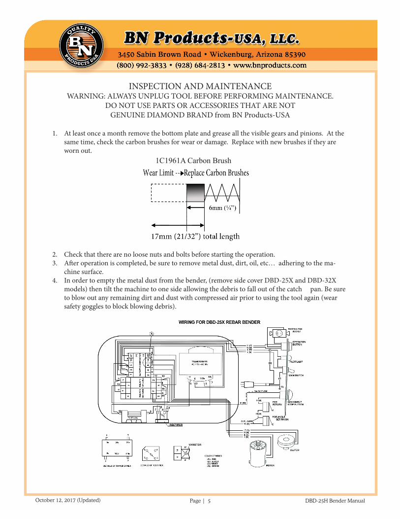
INSPECTION AND MAINTENANCE WARNING: ALWAYS UNPLUG TOOL BEFORE PERFORMING MAINTENANCE.
DO NOT USE PARTS OR ACCESSORIES THAT ARE NOT GENUINE DIAMOND BRAND from BN Products-USA
1. At least once a month remove the bottom plate and grease all the visible gears and pinions. At the same time, check the carbon brushes for wear or damage. Replace with new brushes if they are worn out.
2. Check that there are no loose nuts and bolts before starting the operation.3. After operation is completed, be sure to remove metal dust, dirt, oil, etc… adhering to the ma-
chine surface.4. In order to empty the metal dust from the bender, (remove side cover DBD-25X and DBD-32X
models) then tilt the machine to one side allowing the debris to fall out of the catch pan. Be sure to blow out any remaining dirt and dust with compressed air prior to using the tool again (wear safety goggles to block blowing debris).
1C1961A Carbon Brush

DBD-25H Bender Manual Page | 6October 12, 2017 (Updated)
DBD-25HNo. Part No. Part Name Qty
1 1BR5001 GEAR CASE M 12 1BR5002 GEAR CASE C 13 1BR5203 GEAR CASE PACKING 14 7CB06045 CAP BOLT M6X45 25 7SW006 SPRING WASHER M6 26 7B08050 BOLT M8X50 37 7SW008 SPRING WASHER M8 48 7PW008 PLATE WASHER M8 19 7B08025 BOLT M8X25 1
10 7N008 NUT M8 111 7B10100 BOLT M10X100 412 7PW010 PLATE WASHER M10 413 7SW010 SPRING WASHER M10 414 7N010 NUT M10 415 7B12020 BOLT M12X20 1
No. Part No. Part Name Qty16 7WF12 SEAL WASHER WF12 117 1BR5023 HELICAL GEAR 118 1BR5025 PINION NO.1 119 1BR5024 HELICAL GEAR KEY 220 1BR5009 NEEDLE BEARING TA1212 121 1BR5003 BEARING 6202V 422 1BR5026 GEAR NO.1 123 1BR5027 PINION NO.2 124 1BR5028 GEAR NO.2 125 1BR5029 PINION NO.3 126 1BR5030 PINION KEY 7X7X20 127 1BR5004 BALL BEARING 6204 228 1BR5006 BALL BEARING 6005 129 1BR5015 OIL SEAL SC22-32-7 130 1BR5008 BALL BEARING 6009Z 1

DBD-25H Bender Manual Page | 7October 12, 2017 (Updated)
No. Part No. Part Name Qty31 1BR5016 OIL SEAL SC45-62-9 132 1BR5010 NEEDLE BEARING
TA2230201
33 1BR5011 CIRCLIP AR-30 134 7TMF1341 CLUTCH ASS’Y 135 1BR5043 SHIM 136 1BR5038D CLUTCH ARMATURE
FLANGE1
37 1BR5007 BEARING 6007ZZ 138 1BR5031 BEARING NUT 139 1BR5032 BEARING WASHER 140 1BR5033 GEAR NO.3 141 1BR5035 SHAFT 142 1BR5034 GEAR NO.3 KEY 143 1BR4206200 PINION NO.4 144 1BR5037 PINION KEY 145 1BR5017 OIL SEAL SC30-45-8 146 1BR5047 FLANGE UNIT UCFL205 147 7B14028 BOLT M14X28 248 7SW014 SPRING WASHER M14 249 1BR5012C ARMATURE 150 1BR6200ZZ BALL BEARING 6200ZZ 151 1BR5012B STATOR COIL 152 1BR5012D MOTOR HOUSING 153 1BR5012H BRUSH CAP 254 1BR5012A CARBON BRUSH SET 155 1BR5012E CARBON BRUSH HOLDER 256 1BR5048 MOTOR COVER 157 7B08015 BOLT M8X15 WITH
WASHER1
58 7CB06050 CAP BOLT M6X50 259 7CB06070 CAP BOLT M6X70 260 7SW006 SPRING WASHER M6 461 1BR5044 CLUTCH COVER 262 7PB206008 PAN HEAD BOLT M6X8
W/WASHER4
63 1BR1025600 FRAME 164 1BR2062800 BASE 165 7CB10020 CAP BOLT M10X20 666 1BR5133 DAMPER 167 7SW010 SPRING WASHER M10 1
No. Part No. Part Name Qty68 7N010 NUT M10 169 1BR5063 ADJUSTABLE STOPPER 170 1BR5064 ADJUSTABLE NUT 1 71 1BR5065 ADJUSTABLE HANDLE 172 7SP05008 SPRING PIN Φ5X8 273 1BR3110400 SIDE COVER 274 7PB06010 PAN HEAD BOLT M6X10 875 7SW006 SPRING WASHER M6 876 7PW006 PLATE WASHER M6 877 1BR3110500 DUST COVER 1 78 1BR7121 DUST COVER STAY 479 7SB06050 FLAT HEAD BOLT M6X50 480 7SW006 SPRING WASHER M6 481 7N006 NUT M6 482 1BR5068 MAIN SHAFT 183 1BR2062700 SWIVEL ARM 184 1BR5070 BALL BEARING 6208Z 285 1BR5071 BALL BEARING 6207Z 186 7SRH80 SNAP RING C-80 187 1BR5073 SPACER 188 1BR5074 ROLLER SHAFT 189 7RC08060 SPRING PIN Φ8X60 190 1BR5079 MAIN SHAFT CLAMP 191 7CB10020 CAP BOLT M10X20 292 7CB10025 CAP BOLT M10X25 293 7SW010 SPRING WASHER M10 494 7SS10025 SET SCREW M10X25 195 7N010 NUT M10 196 1BR3110200 SWIVEL GEAR 197 7CB10035 CAP BOLT M10X35 898 7SW010 SPRING WASHER M10 899 7RC08030 SPRING PIN Φ8x30 1
100 1BR5087 LIMIT SWITCH CAM 1101 7SS06006 SET SCREW M6X6 1102 1BR51324 ANGLE SET PINION 1103 1BR3110600 ANGLE LEVER 1104 1BR50942 ANGLE STAND 1105 7B308015 BOLT M8X15 WITH
WASHERS2
106 1BR5098 DISK SPRING M10 2
DBD-25H Bender Manual Page | 8October 12, 2017 (Updated)
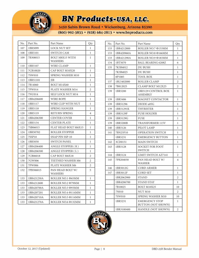
No. Part No. Part Name Qty107 1BR5099 LOCK NUT SET 1108 1BR5101 SWITCH CAM 1109 7B308015 BOLT M8X15 WITH
WASHERS1
110 1BR5107 WIRE CLAMP 1111 7CB10020 CAP BOLT M10X20 1112 7SW010 SPRING WASHER M10 1113 1BR51101 JIB 1114 7B14060 BOLT M14X60 1115 7PW014 PLATE WASHER M14 2116 7NU014 SELF LOCK NUT M14 1117 1BR4206600 WIRE ROPE 1118 1BR5117 WIRE CLIP WITH NUT 1119 1BR5118 SPRING HANGER 1120 1BR5119 RETURN SPRING 4121 1BR4206300 CENTER COVER 1122 1BR5134 CENTER PLATE 1123 7SB06015 FLAT HEAD BOLT M6X15 1124 1BR50782 ROLLER STOPPER 1125 7SSP10 SNAP PIN SSP-10 1126 1BR5050 SWITCH PANEL 1127 1BR4206400 ANGLE STOPPER ( R ) 1128 1BR4206500 ANGLE STOPPER ( L ) 1129 7CB06018 CAP BOLT M6X18 2130 7GW006 TEETHED WASHER M6 2131 7PW006 PLATE WASHER M6 2132 7PB306015 PAN HEAD BOLT W/
WASHERS5
133 1BR421250A ROLLER NO.1 Φ65MM 1133 1BR4212600 ROLLER NO.2 Φ79MM 1133 1BR420700A ROLLER NO.3 Φ93MM 1133 1BR4207201 ROLLER NO.4 Φ114MM 1133 1BR420710A ROLLER NO.5 Φ114MM 1133 1BR421270A ROLLER NO.6 Φ132MM 1
No. Part No. Part Name Qty133 1BR4212800 ROLLER NO.7 Φ153MM 1133 1BR420960A ROLLER NO.8 Φ166MM 1133 1BR421290A ROLLER NO.9 Φ183MM 1134 1BT5070 BALL BEARING 6208Z 6135 7K5B4012 DU BUSH 1
7K5B4025 DU BUSH 18P1085 TOOL BOX 1
137 1BL5402000 ROLLER CLAMP 2138 7B812025 CLAMP BOLT M12X25 2139 1BR5200 1BR5129 CONTROL BOX
ASSEMBLY1
139 1BR5406 MAGNET CONTACTOR 1139 1BR51296 DIODE u05G 1139 1BR51291K THYRISTER 1139 1BR5129F FUSE HOLDER 1139 1BR5129G FUSE 1139 1BR5200B TRANSFORMER 115V 1140 1BR5126 PILOT LAMP 1141 7BN25F10 OPERATION SWITCH 1
1BR5231 EMERGENCY BUTTON 1142 3CD0151 MAIN SWITCH 1143 1BR5128 SOCKET FOR FOOT
SWITCH1
144 1BR5124 LIMIT SWITCH AZ7141 2145 7PB204030 PAN HEAD BOLT W/
WASHER4
146 1BR5012G CORD ARMER 1147 1BR5012F CORD SET 1
1BR2062900 STAND 21BR4206700 STAND STAY 17B10025 BOLT M10X25 107N010 NUT M10 27SW010 SPRING WASHER M10 101BR5231 EMERGENCY STOP
BUTTON (NOT SHOWN)1
1BR3100400 HANDLE (NOT SHOWN) 2