Embed Size (px)
Citation preview
Development kit for DATAMAN 570 Programmer’s Guide
Visual Basic .NET Version 1.00
Copyright © 2004-2008 Dataman Programmers Ltd
Development kit for DATAMAN 570 series Programmer’s Guide Thank you for choosing the Dataman 520 Series Ocilloscope with development kit. We believe it will meet your expectations. For any further information or consultations, please contact us via phone or preferably e-mail on the following address: Address: Dataman Programmers Ltd
Station Road Maiden Newton Dorset DT2 0AE United Kingdom
Phone: Sales/General information: +44 (0) 1300 320719 Technical support: +44 (0) 1300 322903 Fax: All Enquiries: +44 (0) 1300 321012 Internet: URL: http://www.dataman.com/ e-mail: [email protected] - technical support [email protected] - sales [email protected] - other information
- 2 -
Development kit for DATAMAN 570 series Programmer’s Guide
Contents 1. Basic information.......................................................................................................6
1.1. Development kit contents ...................................................................................6 1.2. DK usage.............................................................................................................6 1.3. Application deployment......................................................................................6
2. Controlling the device................................................................................................7 2.1. Device initialization ............................................................................................7 2.2. Error handling .....................................................................................................7 2.3. Data acquisition loop ..........................................................................................7 2.4. Acquired data allocation .....................................................................................8 2.5. Measurement in the sampling mode ...................................................................8
2.5.1. Random sampling method ...........................................................................8 2.5.2. Measurement in sampling mode ................................................................10
3. Reference .................................................................................................................11 3.1. Functions, that returns information about device .............................................12
3.1.1. GetDKError................................................................................................12 3.1.2. ResetDKError ............................................................................................12 3.1.3. GetDeviceID ..............................................................................................12 3.1.4. GetDeviceSerialNumber ............................................................................13 3.1.5. GetDKVersion ...........................................................................................13 3.1.6. GetTimeBaseList .......................................................................................13 3.1.7. GetRangeList .............................................................................................14
3.2. Initialization functions ......................................................................................14 3.2.1. LoadDriver.................................................................................................14 3.2.2. InitHardware ..............................................................................................15
3.3. Functions, that set the data acquisition parameters...........................................15 3.3.1. SetTimeBase ..............................................................................................15 3.3.2. SetRange ....................................................................................................15 3.3.3. SetCoupling................................................................................................16 3.3.4. SetVert .......................................................................................................16 3.3.5. SetTriggerLevel .........................................................................................16 3.3.6. SetTriggerCount.........................................................................................17 3.3.7. SetTriggerLength .......................................................................................17 3.3.8. SetTriggerMode .........................................................................................17 3.3.9. SetAfterTriggerLength...............................................................................18 3.3.10. SetHoldOff ...............................................................................................18 3.3.11. SetTriggerSource .....................................................................................18 3.3.12. SetTriggerEdge ........................................................................................19 3.3.13. SetProbe ...................................................................................................19 3.3.14. SetMemorySize........................................................................................19 3.3.15. SetCompensationGenerator .....................................................................20 3.3.16. SetGround ................................................................................................20 3.3.17. SetDigitalShielding ..................................................................................20
3.4. Data acqusition functions..................................................................................21 3.4.1. StartMeasurement ......................................................................................21 3.4.2. IsDataReady...............................................................................................21 3.4.3. GetReconstructionPercentage ....................................................................21 3.4.4. GetData ......................................................................................................22
- 3 -

Development kit for DATAMAN 570 series Programmer’s Guide
3.5. Other functions..................................................................................................22 3.5.1. GroundPositionToShift ..............................................................................22
- 4 -

Development kit for DATAMAN 570 series Programmer’s Guide
Figures and tables
Table 1.1. –Development kit (DK) contents..................................................................6 Fig. 2.4.1. – Data allocation in the array........................................................................8 Fig. 2.5.1.1. – Random sampling principle....................................................................9
- 5 -
Development kit for DATAMAN 570 series Programmer’s Guide
1. Basic information
1.1. Development kit contents
All development kit (DK) parts are located in the installation directory.
Directory Contents Examples\C#.NET C#.NET example Examples\VB.NET Visual Basic .NET example Examples\VB Visual Basic 6.0 example Examples\Delphi Delphi example Examples\CBuilder C++ Builder example Examples\VC Visual C++ example Include\C#.NET C#.NET header files Include\VB.NET Visual Basic .NET header files Include\VB Visual Basic 6.0 header files Include\Delphi Delphi header files Include\CBuilder C++ Builder header files Include\VC Visual C++ 6.0 header files Bin m570drvdk.dll and m570drv.dll libraries
Table 1.1. –Development kit (DK) contents
1.2. DK usage
In order to make the DK work properly, it is necessary to have the DATAMAN 570 oscilloscope drivers installed. The m570drv.vb header file contains the cm570drv class, which encapsulates all DK functions and constants. Add this file to project to gain access to the cm570drv class. The m570drvdk.dll and m570drv.dll must be present in the same directory as the .exe file is (bin\debug).
1.3. Application deployment
The m570drvdk.dll and m570drv.dll libraries must be distributed together with your application. The drivers for the DATAMAN 570 oscilloscope must be installed in the system in order to communicate with the device. The application will work with every device with an activated DK.
- 6 -
Development kit for DATAMAN 570 series Programmer’s Guide
2. Controlling the device
2.1. Device initialization
First of all, it is necessary to load the driver using thr function LoadDriver. cm570drv.LoadDriver() After the driver is loaded, it is possible to initialize the device using the function InitHardware. This function also returns the information for the calibration data. Dim CalibOK As Byte cm570drv.InitHardware(CalibOK)
2.2. Error handling
In case the error occurs, all subsequent calls of functions will fail. Therefore it is necessary to check if the operations were successful (for example check if the initialization was successful). Use GetDKError to obtain the error code. Dim res As integer res = cm570drv.GetDKError() In case of an error, it is necessary to reset the error flag (to indicate to the DK, that the error has been handled). Use ResetDKError function to do so (otherwise no other function will be successful). cm570drv.ResetDKError()
2.3. Data acquisition loop
The data acquisition process can be started by calling StartMeasurement function. cm570drv.StartMeasurement() After the data acqusition starts, the software must wait until the data is ready in the device. Use IsDataReady function to check the acquisition status. res = cm570drv.IsDataReady() If res = cm570drv.DATA_READY Then End If When the data is ready for transfer to the computer (return value DATA_READY), it is possible to transfer them to the computer using GetData function. Dim Data(1048576) As TSample Dim lng As Integer cm570drv.GetData(Data(0), lng)
- 7 -
Development kit for DATAMAN 570 series Programmer’s Guide 2.4. Acquired data allocation
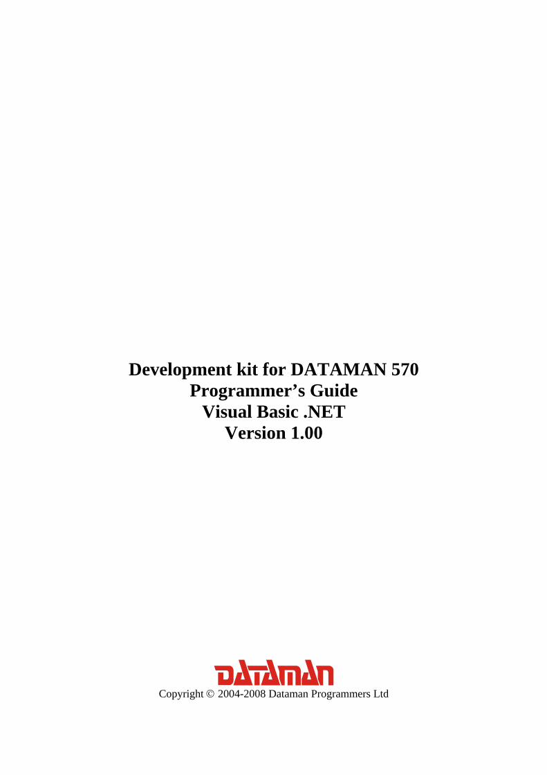
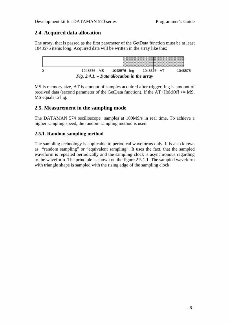
The array, that is passed as the first parameter of the GetData function must be at least 1048576 items long. Acquired data will be written in the array like this:
0 10485751048576 - MS 1048576 - AT1048576 - lng Fig. 2.4.1. – Data allocation in the array
MS is memory size, AT is amount of samples acquired after trigger, lng is amount of received data (second parameter of the GetData function). If the AT+HoldOff >= MS, MS equals to lng.
2.5. Measurement in the sampling mode
The DATAMAN 574 oscilloscope samples at 100MS/s in real time. To achieve a higher sampling speed, the random sampling method is used.
2.5.1. Random sampling method
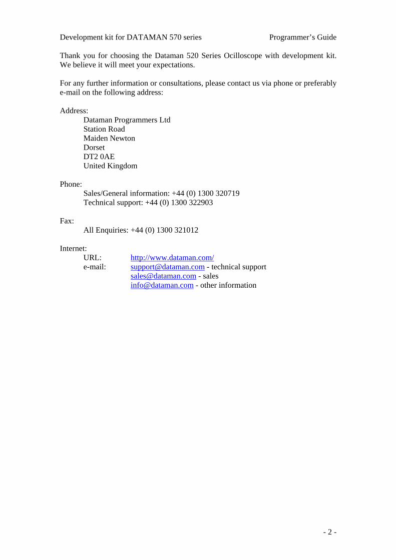
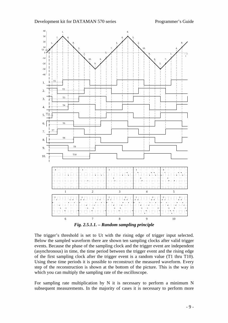
The sampling technology is applicable to periodical waveforms only. It is also known as “random sampling” or “equivalent sampling”. It uses the fact, that the sampled waveform is repeated periodically and the sampling clock is asynchronous regarding to the waveform. The principle is shown on the figure 2.5.1.1. The sampled waveform with triangle shape is sampled with the rising edge of the sampling clock.
- 8 -
Development kit for DATAMAN 570 series Programmer’s Guide
0
1d
2d
3d
4d
-1d
-2d
-3d
-4d
t
Ut
1.
2.
3.
4.
5.
6.
7.
8.
9.
10.
5.
7.
1.
4.
8.
3.
2.
10.
9.
6.
5.
7.
1.
4.
8.
3.
2.
10.
9.
6.
5.
7.
1.
4.
8.
T2
T3
T1
T4
T5
T6
T7
T8
T9
T10
1 2 3 4 5
6 7 8 9 10 Fig. 2.5.1.1. – Random sampling principle
The trigger’s threshold is set to Ut with the rising edge of trigger input selected. Below the sampled waveform there are shown ten sampling clocks after valid trigger events. Because the phase of the sampling clock and the trigger event are independent (asynchronous) in time, the time period between the trigger event and the rising edge of the first sampling clock after the trigger event is a random value (T1 thru T10). Using these time periods it is possible to reconstruct the measured waveform. Every step of the reconstruction is shown at the bottom of the picture. This is the way in which you can multiply the sampling rate of the oscilloscope. For sampling rate multiplication by N it is necessary to perform a minimum N subsequent measurements. In the majority of cases it is necessary to perform more
- 9 -
Development kit for DATAMAN 570 series Programmer’s Guide measurements, because the random nature of this process causes measurements with the same clock phase. When the random sampling method is used, it is necessary to trigger with a well defined and stable waveform.
2.5.2. Measurement in sampling mode
Synthesis and interpolation of the samples is done automatically by the DK. Application received synthetized data. The only difference between real mode and sampling mode is that it is necessary to perform more acquisition loops to get a real image of the signal. Use GetReconstructionPercentage function to get the quality of the signal image (ratio of the measured and calculated samples).
- 10 -
Development kit for DATAMAN 570 series Programmer’s Guide
3. Reference
Functions available in DK can be divided into five groups: Functions, that returns information about device
GetDKError ResetDKError GetDeviceID GetDeviceSerialNumber GetDKVersion GetTimeBaseList GetRangeList Initialization functions LoadDriver InitHardware Functions, that set the data acquisition parameters SetTimeBase SetRange SetCoupling SetVert SetTriggerLevel SetTriggerCount SetTriggerLength SetTriggerMode SetAfterTriggerLength SetHoldOff SetTriggerSource SetTriggerEdge SetProbe SetMemorySize SetCompensationGenerator SetGround SetDigitalShielding Data acquisition functions
StartMeasurement IsDataReady GetReconstructionPercentage GetData Other functions GroundPositionToShift
- 11 -
Development kit for DATAMAN 570 series Programmer’s Guide
3.1. Functions, that returns information about device
3.1.1. GetDKError
In the case where the error occurs during the call of any DK function the error code is stored in the DK internal variable. All subsequent calls of DK functions will fail. GetDKError returns error code. Declaration:
Public Shared Function GetDKError() As Integer Parameters: - Return value:
ERROR_OK – no error occured ERROR_DRIVER_NOT_LOADED – unable to load driver/driver wasn’t
loaded before call ERROR_DRIVER_INCOMPATIBLE - driver is not compatible with DK ERROR_UNABLE_TO_LOAD_EM57X – unable to load em57x driver ERROR_INIT_FAILED – device initialization failed ERROR_FPGA_CONFIG_FAILED – FPGA configuration failed ERROR_COMMUNICATION_FAILED – the communication with device is
broken ERROR_OPERATION_FAILED – unable to finish last operation ERROR_DK_NOT_ENABLED – the device doesn’t have DK enabled ERROR_INCORRECT_PARAMETER – the function was called with incorrect
parameter value
3.1.2. ResetDKError
In the case where the error occurs during the call of any DK function the error code is stored in the DK internal variable. All subsequent calls of any DK functions will fail. ResetDKError function resets this variable, thus allowing you to call the DK functions again. Declaration:
Public Shared Sub ResetDKError() Parameters: - Return value: -
3.1.3. GetDeviceID
Returns ID of the connected device.
Public Shared Function GetDeviceID() As Integer
- 12 -
Development kit for DATAMAN 570 series Programmer’s Guide Parameters: - Return value: Device code is calculated as 571+return value.
3.1.4. GetDeviceSerialNumber
Returns device serial number.
Public Shared Function GetDeviceSerialNumber() As Integer Parameters: - Return value: Device serial number.
3.1.5. GetDKVersion
Returns the version of the selected DK part.
Public Shared Sub GetDKVersion(ByVal moduleindex As Integer, ByRef ver As TDKVersion) Parameters: module – identifies DK part, which version is to be obtained VERSION_EM570 – em570 driver VERSION_DK – DK (m570drvdk.dll) version – structure, which will be filled with the version Return value: -
3.1.6. GetTimeBaseList
Returns the list of available timebases.
Public Shared Sub GetTimeBaseList(ByRef items As TTimeBaseItem, ByRef itemcount As Integer) Parameteres: timebaselist – the first item of the array which will be filled with the available timebases. Array must be at least 31 items long. timebaselistlength – the number of array items which was filled (number of available timebases) Return value: - Remark: Each array item is of TTimeBaseItem type. This structure comprises of the following items:
- 13 -
Development kit for DATAMAN 570 series Programmer’s Guide
nsPerDiv – amount of nanoseconds per screen division (50 samples); this value is passed to the SetTimeBase function
RealSamplingRate – real sampling rate (in case, that the timebase doesn’t run in sampling mode, this value equals to SamplingRate)
SamplingRate – equivalent sampling rate; this frequency determines distance between two samples
SamplingMulti – indicates ratio of SamplingRate and RealSamplingRate; the value of 1 indicates sampling in real time, value greater than 1 indicates sampling mode
3.1.7. GetRangeList
Returns the list of available ranges.
Public Shared Sub GetRangeList(ByRef items As TRangeItem, ByRef itemcount As Integer) Parameters: rangelist – the first item of the array which will be filled with the available ranges. Array must be at least 13 items long. rangelistlength – the number of array items which was filled (number of available ranges) Return value: - Remark: Each array item is of TRangeItem type. This structure comprise of following items: mVPerDiv – amount of mV per one screen division (32 quantization levels); this value is passed to the SetRange function
3.2. Initialization functions
3.2.1. LoadDriver
Loads m570drv.dll driver.
Public Shared Function LoadDriver() As Integer Parameters: - Return value: ERROR_OK – driver loaded successfully ERROR_DRIVER_NOT_LOADED – unable to load m570drv.dll library ERROR_DRIVER_INCOMPATIBLE – m570drv.dll isn’t compatible with DK Remark: The return value is stored in the internal DK variable as well. Use GetDKError function to access this internal variable.
- 14 -
Development kit for DATAMAN 570 series Programmer’s Guide 3.2.2. InitHardware
Initializes device. After successful call of this function, the device can be used.
Public Shared Function InitHardware(ByRef CalibOK As Byte) As Integer Parameters: CalibOK – this variable will be filled with information whether the calibration data in the device is ok 1 – calibration data are ok 0 – calibration data in the device are broken Return value: ERROR_OK – device was initialized successfully ERROR_UNABLE_TO_LOAD_EM57X – unable to load em57x driver ERROR_INIT_FAILED – device initialization failed (one of the reason can be, that the device isn’t connected) ERROR_FPGA_CONFIG_FAILED – FPGA initialization failed ERROR_DK_NOT_ENABLED – the DK isn’t enabled in the connected device ERROR_DRIVER_NOT_LOADED – the driver m570drv.dll wasn’t loaded before this call (use LoadDriver function to load it)
3.3. Functions, that set the data acquisition parameters
3.3.1. SetTimeBase
Sets selected timebase.
Public Shared Sub SetTimeBase(ByVal ns As Integer) Parameters: ns – amount of nanoseconds per one division (50 samples) Return value: - Remark: The list of available timebases can be obtained by GetTimeBaseList function.
3.3.2. SetRange
Sets selected range to the selected channel.
Public Shared Function SetRange(ByVal channel As Integer, ByVal mV As Integer) As Integer Parameters: channel – determines channel CHANNEL_A – channel A CHANNEL_B – channel B mV – determines range, which is to be set (amount of mV per division)
- 15 -
Development kit for DATAMAN 570 series Programmer’s Guide Return value: The vertical shift which must be set to keep the position of 0V at the same place. Remark: If it is necessary to keep the 0V position on the screen intact, it is necessary to set the vertical shift using function SetVert to the return value.
3.3.3. SetCoupling
Sets selected coupling on the channel.
Public Shared Sub SetCoupling(ByVal channel As Integer, ByVal coupling As Integer) Parameters: channel – determines channel CHANNEL_A – channel A CHANNEL_B – channel B coupling – determines coupling COUPLING_AC – AC coupling COUPLING_DC – DC coupling Return value: -
3.3.4. SetVert
Sets specified shift to the selected channel.
Public Shared Function SetVert(ByVal channel As Integer, ByVal shift As Integer) As Integer Parameters: channel – determines channel CHANNEL_A – channel A CHANNEL_B – channel B shift – shift value from 0 to 4095, where 0 moves the waveform maximally downwards and 4095 moves the waveform maximally upwards Return value: Position on the screen (quantization level), which corresponds with 0V.
3.3.5. SetTriggerLevel
Sets threshold on the selected source.
Public Shared Sub SetTriggerLevel(ByVal channel As Integer, ByVal level As Integer) Parameters:
- 16 -
Development kit for DATAMAN 570 series Programmer’s Guide channel – determines channel CHANNEL_A – channel A CHANNEL_B – channel B level – determines quantization level (0 to 255), which will be considered as threshold Return value: -
3.3.6. SetTriggerCount
Sets amount of trigger events necessary to start acquisition on the selected trigger level.
Public Shared Sub SetTriggerCount(ByVal level As Integer, ByVal amount As Integer) Parameters: level – determines level of the trigger system TRIGGER_LEVEL_PRIMARY – primary level TRIGGER_LEVEL_SECONDARY – secondary level amount – amount of trigger events necessary to start acquisition Return value: -
3.3.7. SetTriggerLength
Sets minimal length of valid trigger event.
Public Shared Sub SetTriggerLength(ByVal level As Integer, ByVal samples As Integer) Parameters: level – determines level of the trigger system TRIGGER_LEVEL_PRIMARY – primary level TRIGGER_LEVEL_SECONDARY – secondary level samples – minimal length of the valid trigger event from 8 to 131068 with step of 4. Value 0 turns the digital filter off. Return value: -
3.3.8. SetTriggerMode
Sets trigger mode.
Public Shared Sub SetTriggerMode(ByVal mode As Integer) Parameters: mode – trigger mode
TRIGGER_MODE_AUTO – in case, that the trigger event doesn’t occur for longer time, the acquisition starts anyway
- 17 -
Development kit for DATAMAN 570 series Programmer’s Guide
TRIGGER_MODE_NORMAL – the acquisition starts only on valid trigger event
TRIGGER_MODE_MANUAL – the acquisition starts immediately after call of StartMeasurement function Return value: -
3.3.9. SetAfterTriggerLength
Sets amount of samples acquired after trigger event.
Public Shared Sub SetAfterTriggerLength(ByVal samples As Integer) Parameters: samples – amount of samples acquired after trigger event (from 1 to 1048576 samples) Return value: -
3.3.10. SetHoldOff
Sets length of hold-off. Public Shared Sub SetHoldOff(ByVal samples As Integer) Parameters: samples – length of hold-off in samples from 4 to 1048576 with step of 4 Return value: -
3.3.11. SetTriggerSource
Sets selected trigger sources on the selected level of the trigger system.
Public Shared Sub SetTriggerSource(ByVal level As Integer, ByVal sources As Integer) Parameters: level – determines level of the affected trigger system TRIGGER_LEVEL_PRIMARY – primary level TRIGGER_LEVEL_SECONDARY – secondary level sources – sum of following constants determines selected sources:
TRIGGER_SOURCE_A – channel A TRIGGER_SOURCE_B – channel B TRIGGER_SOURCE_E – external trigger input
Return value: -
- 18 -
Development kit for DATAMAN 570 series Programmer’s Guide 3.3.12. SetTriggerEdge
Sets triggering on the selected edge (leading or trailing) on the selected source.
Public Shared Sub SetTriggerEdge(ByVal level As Integer, ByVal source As Integer, ByVal edge As Integer) Parameters: level – determines level of the affected trigger system TRIGGER_LEVEL_PRIMARY – primary level TRIGGER_LEVEL_SECONDARY – secondary level source – determines the source, whose sensitivity is affected
TRIGGER_SOURCE_A – channel A TRIGGER_SOURCE_B – channel B TRIGGER_SOURCE_E – external trigger input
edge – determines sensitivity TRIGGER_EDGE_LEADING – sensitivity on the leading edge TRIGGER_EDGE_TRAILING – sensitivity on the trailing edge
Return value: -
3.3.13. SetProbe
Sets device to measure with selected probe accurately.
Public Shared Sub SetProbe(ByVal channel As Integer, ByVal probe As Integer) Parameters: channel – determines channel CHANNEL_A – channel A CHANNEL_B – channel B probe – determines connected probe
PROBE_1_1 – probe 1:1 PROBE_1_10 – probe with attenuation 1:10 or higher
Return value: - Remark: This function sets correction of the input impedance inaccuracy. This correction is turned on with probes with attenuation of 1:10 or higher.
3.3.14. SetMemorySize
Sets length of memory used for data acquisition.
Public Shared Sub SetMemorySize(ByVal size As Integer) Parameters:
- 19 -
Development kit for DATAMAN 570 series Programmer’s Guide size – length of memory used for data acquisition (valid values are: 1024, 2048, 4096, 8192, 16384, 32768, 65536, 131072, 262144, 524288 and 1048576) Return value: -
3.3.15. SetCompensationGenerator
Turns compensation generator (square wave with frequency of 1.465kHz on the E connector) on/off.
Public Shared Sub SetCompensationGenerator(ByVal OnOff As Integer) Parameters: onoff – determines whether the compensation generator should be turned on/off ONOFF_OFF – turns generator off ONOFF_ON – turns generator on Return value: -
3.3.16. SetGround
Grounds inputs on the selected channel.
Public Shared Sub SetGround(ByVal channel As Integer, ByVal OnOff As Integer) Parameters: channel – determines channel CHANNEL_A – channel A CHANNEL_B – channel B
onoff – determines, whether the channel should be grounded ONOFF_OFF – grounds channel
ONOFF_ON – disconnects channel from ground Return value: -
3.3.17. SetDigitalShielding
Turns digital shielding on the selected channel on/off.
Public Shared Sub SetDigitalShielding(ByVal channel As Integer, ByVal OnOff As Integer, ByVal level As Integer) Parametre: channel – determines channel CHANNEL_A – channel A CHANNEL_B – channel B onoff – determines whether the digital shielding will be turned on or off ONOFF_OFF – turns the digital shielding off ONOFF_ON – turns the digital shielding on
- 20 -
Development kit for DATAMAN 570 series Programmer’s Guide level – determines the digital shielding factor (valid values are: 2, 4, 8, 16, 32 and 64) Return value: - Remark: In order to make the digital shielding work correctly, it is necessary to have a stable and well triggered signal on the input. Digital shielding prolongs the oscilloscope response to the signal change (the higher the factor the longer the response).
3.4. Data acqusition functions
3.4.1. StartMeasurement
Starts/restarts data acquisition.
Public Shared Sub StartMeasurement() Parameters: - Return value: -
3.4.2. IsDataReady
Returns the data acquisition status.
Public Shared Function IsDataReady() As Integer Parameters: - Return value: Indicates data acquisition status. It is one of following constants:
DATA_NOT_TRIGGERED – valid trigger event hasn’t occured DATA_TRIGGERED – the acquisition is triggered and is in progress DATA_READY – the acquisition is finished, data are prepared to be
transferred to computer. This transfer can be done by GetData function. DATA_ERROR – the communication with device is broken, it is not
possible to determine acquisition status
3.4.3. GetReconstructionPercentage
Returns ratio of the measured data to measured data + interpolated data.
Public Shared Sub GetReconstructionPercentage(ByRef channelA As Integer, ByRef channelB As Integer) Parameters: channelA – amount of channel A, that was measured (percentage) channelB – amount of channel B, that was measured (percentage)
- 21 -
Development kit for DATAMAN 570 series Programmer’s Guide
- 22 -
Return value: - Remark: This function works only in case, that the selected timebase uses sampling mode (SamplingMulti > 1).
3.4.4. GetData
Transfers data from device to computer.
Public Shared Sub GetData(ByRef Data As TSample, ByRef returnedlength As Integer) Parameters: data – array, which contains 1048576 items of TSample type. This array is filled with the data transferred from the device. Last transferred sample from device is written to the end of array (item index 1048575), first sample is written to the item index 1048576 - length length – amount of samples, that were transferred from device Return value: -
3.5. Other functions
3.5.1. GroundPositionToShift
Returns vertical shift, which is necessary to set, to have the 0V at the selected position of the screen (quantization level).
Public Shared Function GroundPositionToShift(ByVal channel As Integer, ByVal Position As Integer) As Integer Parameters: channel – determines channel CHANNEL_A – channel A CHANNEL_B – channel B position – screen position (quantization level), where the 0V should be placed Return value: The vertical shift value, which places 0V to the selected screen position (quantization level). Set this value using SetVert to place 0V to the selected position.