Embed Size (px)
Citation preview

DataMan® 360 SeriesReferenceManual
04/26/2017Version: 5.7.0.361

Legal NoticesThe software described in this document is furnished under license, and may be used or copied only in accordance withthe terms of such license and with the inclusion of the copyright notice shown on this page. Neither the software, thisdocument, nor any copies thereof may be provided to, or otherwise made available to, anyone other than the licensee.Title to, and ownership of, this software remains with Cognex Corporation or its licensor. Cognex Corporation assumesno responsibility for the use or reliability of its software on equipment that is not supplied by Cognex Corporation.Cognex Corporation makes no warranties, either express or implied, regarding the described software, itsmerchantability, non-infringement or its fitness for any particular purpose.
The information in this document is subject to change without notice and should not be construed as a commitment byCognex Corporation. Cognex Corporation is not responsible for any errors that may be present in either this document orthe associated software.
Companies, names, and data used in examples herein are fictitious unless otherwise noted. No part of this documentmay be reproduced or transmitted in any form or by any means, electronic or mechanical, for any purpose, nortransferred to any other media or language without the written permission of Cognex Corporation.
Copyright © 2017. Cognex Corporation. All Rights Reserved.
Portions of the hardware and software provided by Cognex may be covered by one or more U.S. and foreign patents, aswell as pending U.S. and foreign patents listed on the Cognex web site at: http://www.cognex.com/patents.
The following are registered trademarks of Cognex Corporation:
Cognex, 2DMAX, Advantage, AlignPlus, Assemblyplus, Check it with Checker, Checker, Cognex Vision for Industry,Cognex VSOC, CVL, DataMan, DisplayInspect, DVT, EasyBuilder, Hotbars, IDMax, In-Sight, Laser Killer, MVS-8000,OmniView, PatFind, PatFlex, PatInspect, PatMax, PatQuick, SensorView, SmartView, SmartAdvisor, SmartLearn,UltraLight, Vision Solutions, VisionPro, VisionView
The following are trademarks of Cognex Corporation:
The Cognex logo, 1DMax, 3D-Locate, 3DMax, BGAII, CheckPoint, Cognex VSoC, CVC-1000, FFD, iLearn, In-Sight(design insignia with cross-hairs), In-Sight 2000, InspectEdge, Inspection Designer, MVS, NotchMax, OCRMax,PatMax RedLine, ProofRead, SmartSync, ProfilePlus, SmartDisplay, SmartSystem, SMD4, VisiFlex, Xpand
Other product and company trademarks identified herein are the trademarks of their respective owners.
2
Legal Notices
Table of ContentsLegal Notices 2Table of Contents 3Symbols 5Getting Started 6About the DataMan 360 Readers 6For More Information... 6Accessories 7M12/S-Mount Lens Options 7Lens Covers 8External Lights (Red LED) 9Laser Aimers 9High Power Illuminations 9Cables 10Power Supplies 10Mounting Brackets 11
DataMan 360 Systems 12
Setting Up Your DataMan 360 13Reader Layout 13Dimensions 15Installing the Lens 17Installing anM12 Lens with Manual Focus 17Installing a Liquid Lens 19Installing a 19mm Liquid Lens 22Installing the 24mm Liquid Lens module with DM360-HPIL-RE-01 or DM360-HPIL-RE-P-01 27Installing a C-Mount Lens 30
Installing a Filter 32External Light Mounting Brackets 36Setting Focus 38Field of View and Reading Distances 40Reading Distance and Field of View (DataMan 360 Readers with a 10.3mm Lens) 40Reading Distance and Field of View (DataMan 360 Readers with a 16mm Lens) 41Reading Distance and Field of View (DataMan 360 Readers with a 19mm Lens with a Liquid Lens) 42Reading Distance and Field of View (DataMan 360 Readers with a 24mm Lens with Liquid Lens) 43Reading Distance and Field of View (DataMan 360 Readers with a 25mm Lens) 44
DataMan 360 Series Specifications 46DataMan 360 Series Imager Specifications 47Illumination Options 47
Using Your DataMan 360 49Installing DataMan Software and Connecting the Reader 49Troubleshooting an Ethernet Connection 49Industrial Protocols 50DataMan 360 Series Triggering 50External Triggers 52DataMan 360 Series Multi-Reader Triggering 53DataMan 360 Series Tuning 53
3
Table of Contents
DataMan 360 Series Image Filtering 56Training the Reader 57Training Feedback 57Incremental Training for Multiple Symbologies 58
Package Detection Support 58
Connections, Optics, and Lighting 59External Light Control 595m Breakout Cable (CCBL-05-01) 605m Breakout Cable (CCB-M12x12Fy-xx) 6115m Breakout Cable (CCB-PWRIO-15) 62High-SpeedOutputs 63High-SpeedOutput Wiring 64Ethernet M12 to RJ45 Cable (CCB-84901-y00x-xx) 65Acquisition Trigger 65Connecting the Encoder to a DataManReader 66Multi-port Connections 66
Cleaning/Maintenance 69Cleaning the Reader Housing 69Cleaning the Reader Lens Cover 69
Compliance Information, Warnings and Notices 70Precautions 70Regulations/Conformity 70Laser Safety Statement 71LED Safety Statement 71For European Community Users 71
Reader Programming Codes 72
4
Table of Contents

SymbolsThe following symbols indicate safety precautions and supplemental information.
WARNING: This symbol indicates the presence of a hazard that could result in death, serious personal injury orelectrical shock.
CAUTION: This symbol indicates the presence of a hazard that could result in property damage.
Note: Notes provide supplemental information about a subject.
Tip: Tips provide helpful suggestions and shortcuts that may not otherwise be apparent.
5
Symbols
Getting StartedThis section provides general information about the DataMan 360 series readers as well as about the DataMan 360accessories and systems.
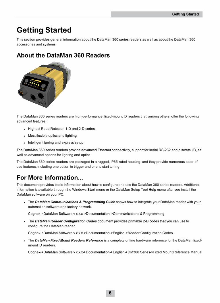
About the DataMan 360 Readers
The DataMan 360 series readers are high-performance, fixed-mount ID readers that, among others, offer the followingadvanced features:
l Highest Read Rates on 1-D and 2-D codes
l Most flexible optics and lighting
l Intelligent tuning and express setup
The DataMan 360 series readers provide advanced Ethernet connectivity, support for serial RS-232 and discrete I/O, aswell as advanced options for lighting and optics.
The DataMan 360 series readers are packaged in a rugged, IP65-rated housing, and they provide numerous ease-of-use features, including one button to trigger and one to start tuning.
For More Information...This document provides basic information about how to configure and use the DataMan 360 series readers. Additionalinformation is available through the Windows Start menu or the DataMan Setup Tool Helpmenu after you install theDataMan software on your PC:
l The DataMan Communications & Programming Guide shows how to integrate your DataMan reader with yourautomation software and factory network.
Cognex->DataMan Software v x.x.x->Documentation->Communications & Programming
l The DataMan Reader Configuration Codes document provides printable 2-D codes that you can use toconfigure the DataMan reader.
Cognex->DataMan Software v x.x.x->Documentation->English->Reader Configuration Codes
l The DataMan Fixed Mount Readers Reference is a complete online hardware reference for the DataMan fixed-mount ID readers.
Cognex->DataMan Software v x.x.x->Documentation->English->DM360 Series->Fixed Mount Reference Manual
6
Getting Started
l The DataMan Questions and Answers document provides context-sensitive information. You can view this helpinside the Setup Tool or as a stand-alone help file.
Cognex->DataMan Software v x.x.x->Documentation->DM360 Series->Questions and Answers
l The Release Notes list detailed system requirements and additional information about this DataMan softwarerelease.
Cognex->DataMan Software v x.x.x->Documentation->DataMan v x.x.x Release Notes
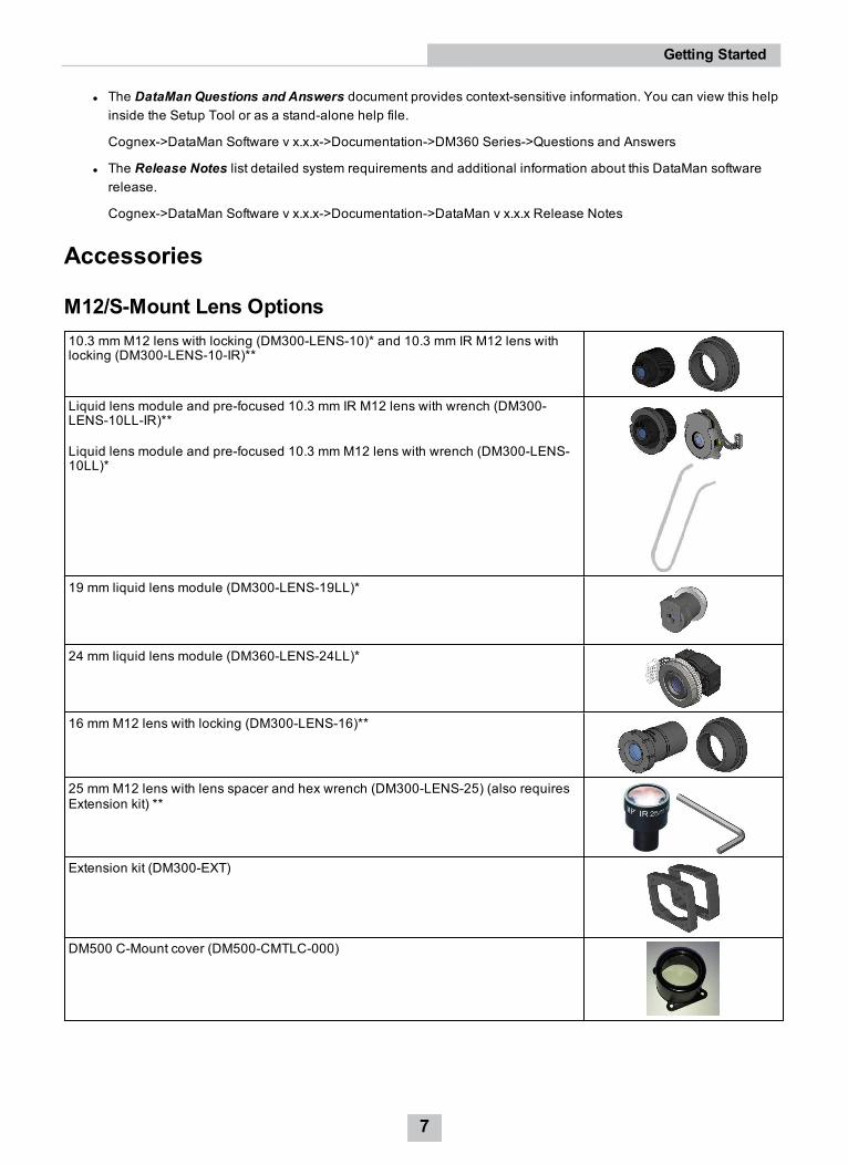
Accessories
M12/S-Mount Lens Options10.3 mm M12 lens with locking (DM300-LENS-10)* and 10.3 mm IR M12 lens withlocking (DM300-LENS-10-IR)**
Liquid lens module and pre-focused 10.3 mm IR M12 lens with wrench (DM300-LENS-10LL-IR)**
Liquid lens module and pre-focused 10.3 mm M12 lens with wrench (DM300-LENS-10LL)*
19 mm liquid lens module (DM300-LENS-19LL)*
24 mm liquid lens module (DM360-LENS-24LL)*
16 mm M12 lens with locking (DM300-LENS-16)**
25 mm M12 lens with lens spacer and hex wrench (DM300-LENS-25) (also requiresExtension kit) **
Extension kit (DM300-EXT)
DM500 C-Mount cover (DM500-CMTLC-000)
7
Getting Started
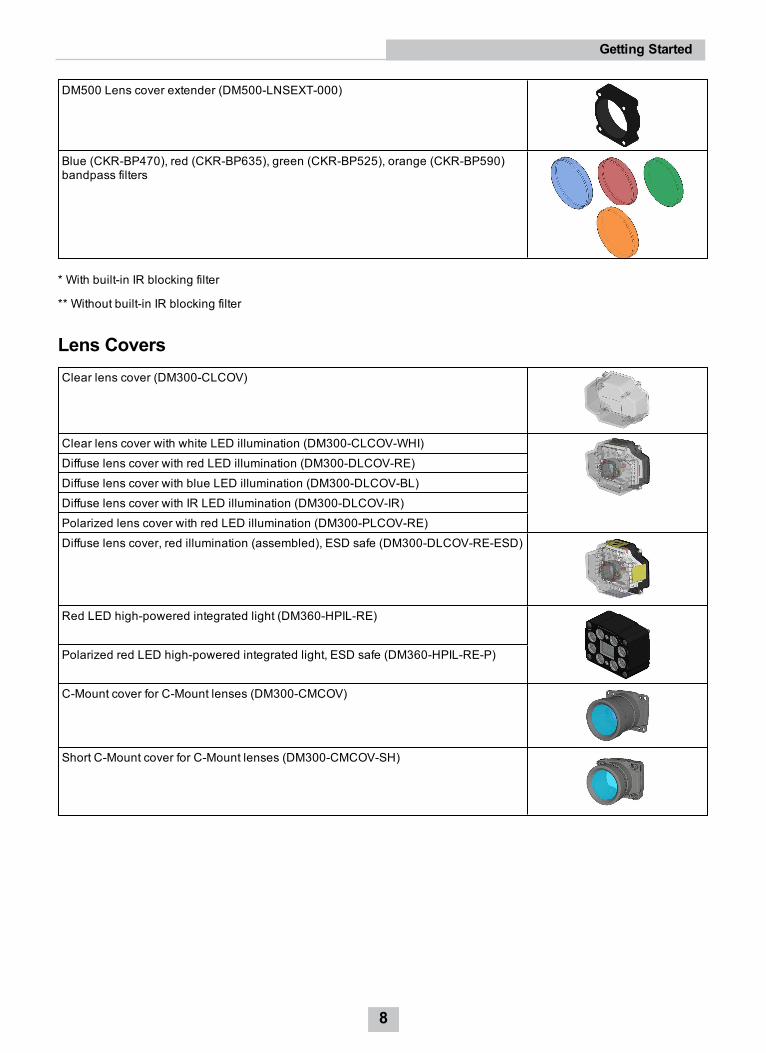
DM500 Lens cover extender (DM500-LNSEXT-000)
Blue (CKR-BP470), red (CKR-BP635), green (CKR-BP525), orange (CKR-BP590)bandpass filters
* With built-in IR blocking filter
** Without built-in IR blocking filter
Lens CoversClear lens cover (DM300-CLCOV)
Clear lens cover with white LED illumination (DM300-CLCOV-WHI)Diffuse lens cover with red LED illumination (DM300-DLCOV-RE)Diffuse lens cover with blue LED illumination (DM300-DLCOV-BL)Diffuse lens cover with IR LED illumination (DM300-DLCOV-IR)Polarized lens cover with red LED illumination (DM300-PLCOV-RE)Diffuse lens cover, red illumination (assembled), ESD safe (DM300-DLCOV-RE-ESD)
Red LED high-powered integrated light (DM360-HPIL-RE)
Polarized red LED high-powered integrated light, ESD safe (DM360-HPIL-RE-P)
C-Mount cover for C-Mount lenses (DM300-CMCOV)
Short C-Mount cover for C-Mount lenses (DM300-CMCOV-SH)
8
Getting Started
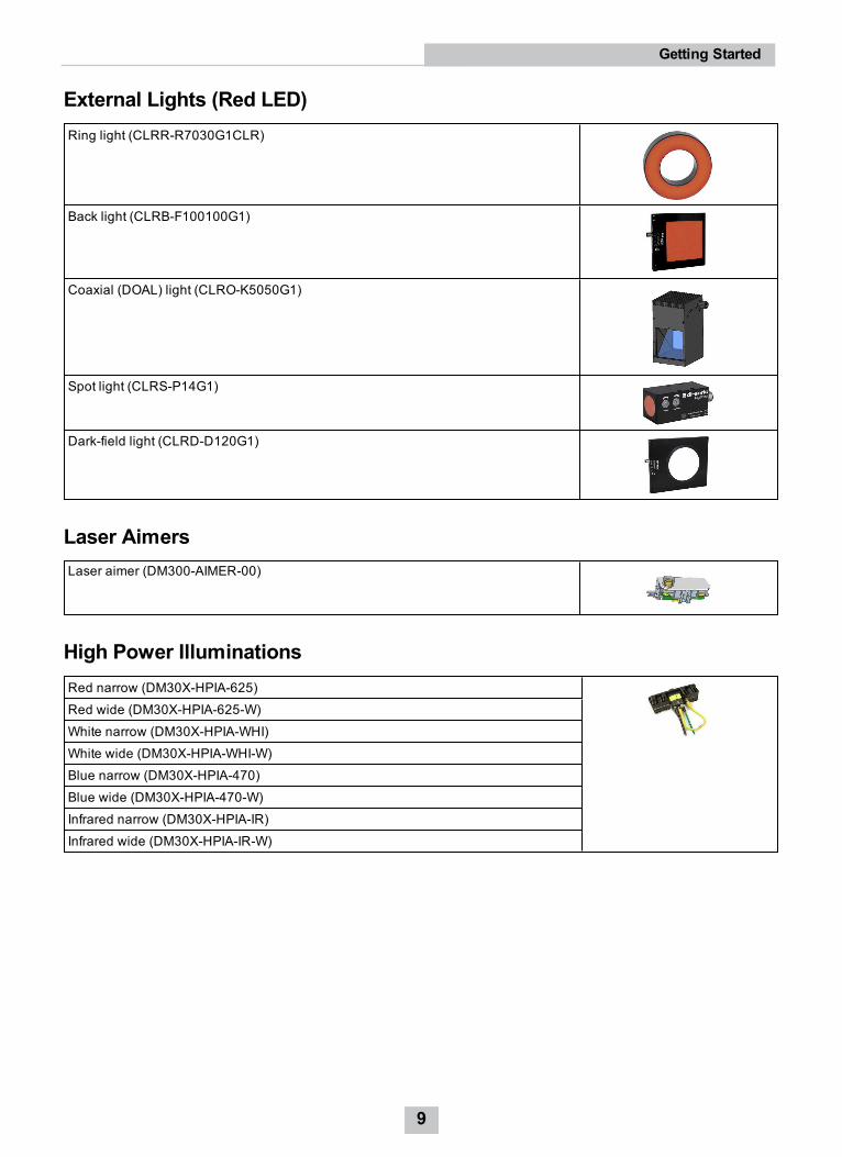
External Lights (Red LED)Ring light (CLRR-R7030G1CLR)
Back light (CLRB-F100100G1)
Coaxial (DOAL) light (CLRO-K5050G1)
Spot light (CLRS-P14G1)
Dark-field light (CLRD-D120G1)
Laser AimersLaser aimer (DM300-AIMER-00)
High Power IlluminationsRed narrow (DM30X-HPIA-625)Red wide (DM30X-HPIA-625-W)White narrow (DM30X-HPIA-WHI)White wide (DM30X-HPIA-WHI-W)Blue narrow (DM30X-HPIA-470)Blue wide (DM30X-HPIA-470-W)Infrared narrow (DM30X-HPIA-IR)Infrared wide (DM30X-HPIA-IR-W)
9
Getting Started
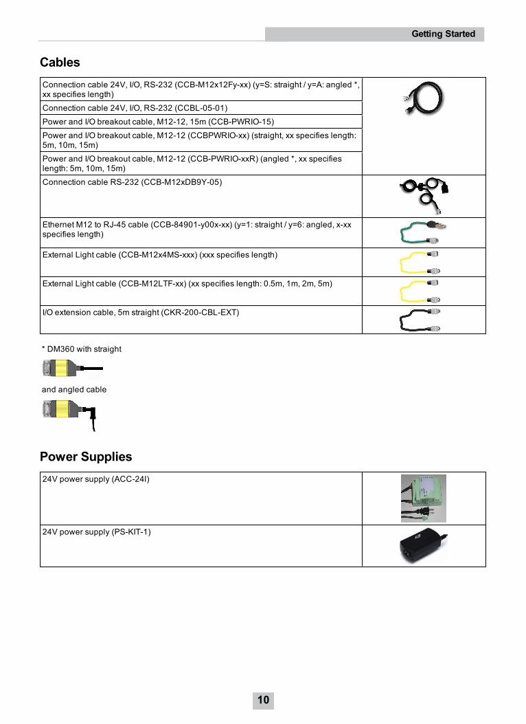
CablesConnection cable 24V, I/O, RS-232 (CCB-M12x12Fy-xx) (y=S: straight / y=A: angled *,xx specifies length)Connection cable 24V, I/O, RS-232 (CCBL-05-01)Power and I/O breakout cable, M12-12, 15m (CCB-PWRIO-15)Power and I/O breakout cable, M12-12 (CCBPWRIO-xx) (straight, xx specifies length:5m, 10m, 15m)Power and I/O breakout cable, M12-12 (CCB-PWRIO-xxR) (angled *, xx specifieslength: 5m, 10m, 15m)Connection cable RS-232 (CCB-M12xDB9Y-05)
Ethernet M12 to RJ-45 cable (CCB-84901-y00x-xx) (y=1: straight / y=6: angled, x-xxspecifies length)
External Light cable (CCB-M12x4MS-xxx) (xxx specifies length)
External Light cable (CCB-M12LTF-xx) (xx specifies length: 0.5m, 1m, 2m, 5m)
I/O extension cable, 5m straight (CKR-200-CBL-EXT)
* DM360 with straight
and angled cable
Power Supplies24V power supply (ACC-24l)
24V power supply (PS-KIT-1)
10
Getting Started
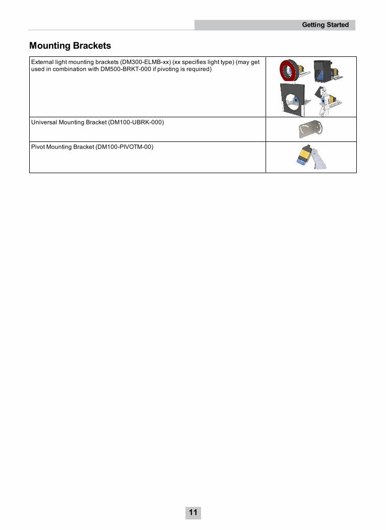
Mounting BracketsExternal light mounting brackets (DM300-ELMB-xx) (xx specifies light type) (may getused in combination with DM500-BRKT-000 if pivoting is required)
Universal Mounting Bracket (DM100-UBRK-000)
Pivot Mounting Bracket (DM100-PIVOTM-00)
11
Getting Started
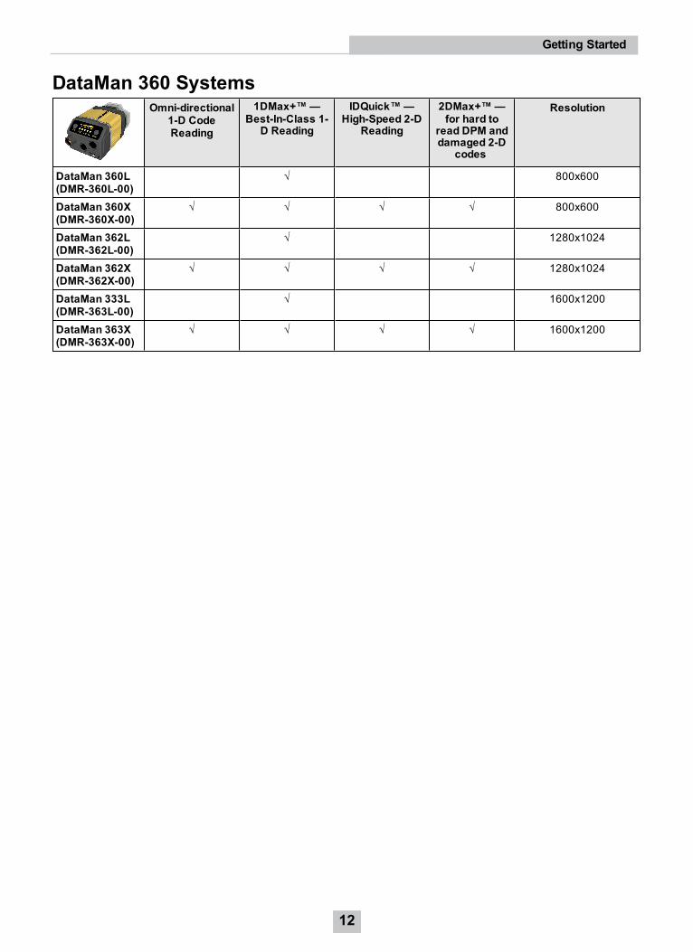
DataMan 360 SystemsOmni-directional
1-D CodeReading
1DMax+™—Best-In-Class 1-
D Reading
IDQuick™—High-Speed 2-D
Reading
2DMax+™—for hard to
read DPM anddamaged 2-D
codes
Resolution
DataMan 360L(DMR-360L-00)
√ 800x600
DataMan 360X(DMR-360X-00)
√ √ √ √ 800x600
DataMan 362L(DMR-362L-00)
√ 1280x1024
DataMan 362X(DMR-362X-00)
√ √ √ √ 1280x1024
DataMan 333L(DMR-363L-00)
√ 1600x1200
DataMan 363X(DMR-363X-00)
√ √ √ √ 1600x1200
12
Getting Started
Setting Up Your DataMan 360This section provides information on the physical appearance of the DataMan 360 reader. It also details the steps ofinstalling the lenses and filters of the reader, and gives information on the imager itself.
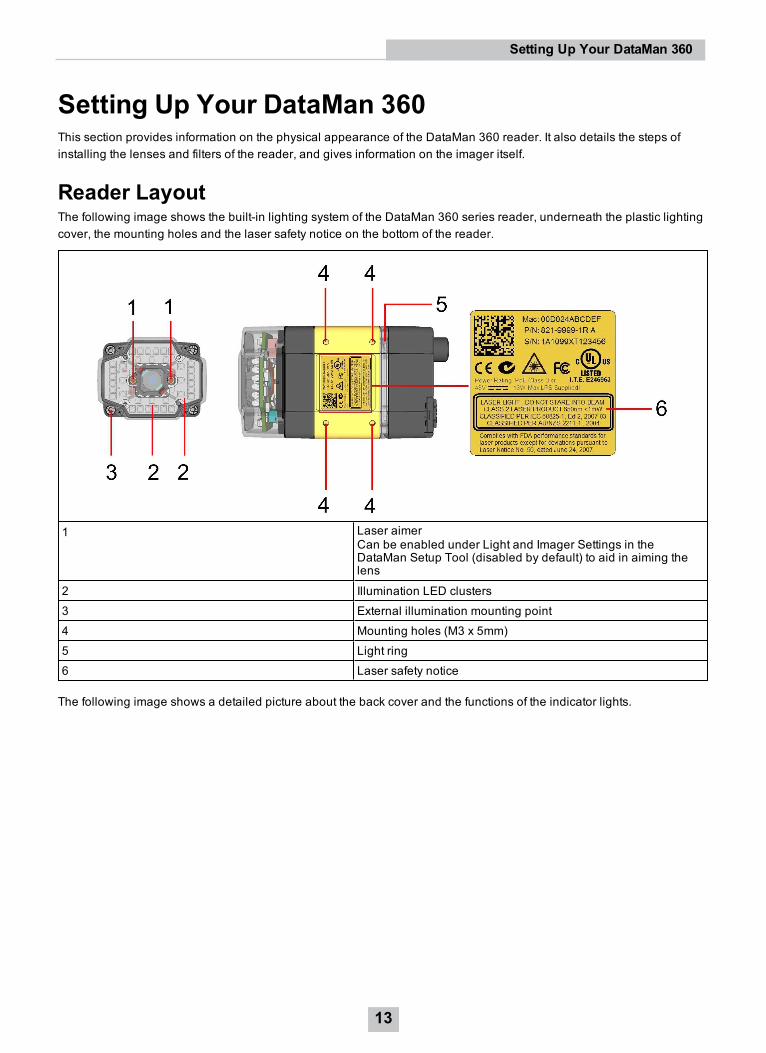
Reader LayoutThe following image shows the built-in lighting system of the DataMan 360 series reader, underneath the plastic lightingcover, the mounting holes and the laser safety notice on the bottom of the reader.
1 Laser aimerCan be enabled under Light and Imager Settings in theDataMan Setup Tool (disabled by default) to aid in aiming thelens
2 Illumination LED clusters3 External illumination mounting point4 Mounting holes (M3 x 5mm)5 Light ring6 Laser safety notice
The following image shows a detailed picture about the back cover and the functions of the indicator lights.
13
Setting Up Your DataMan 360
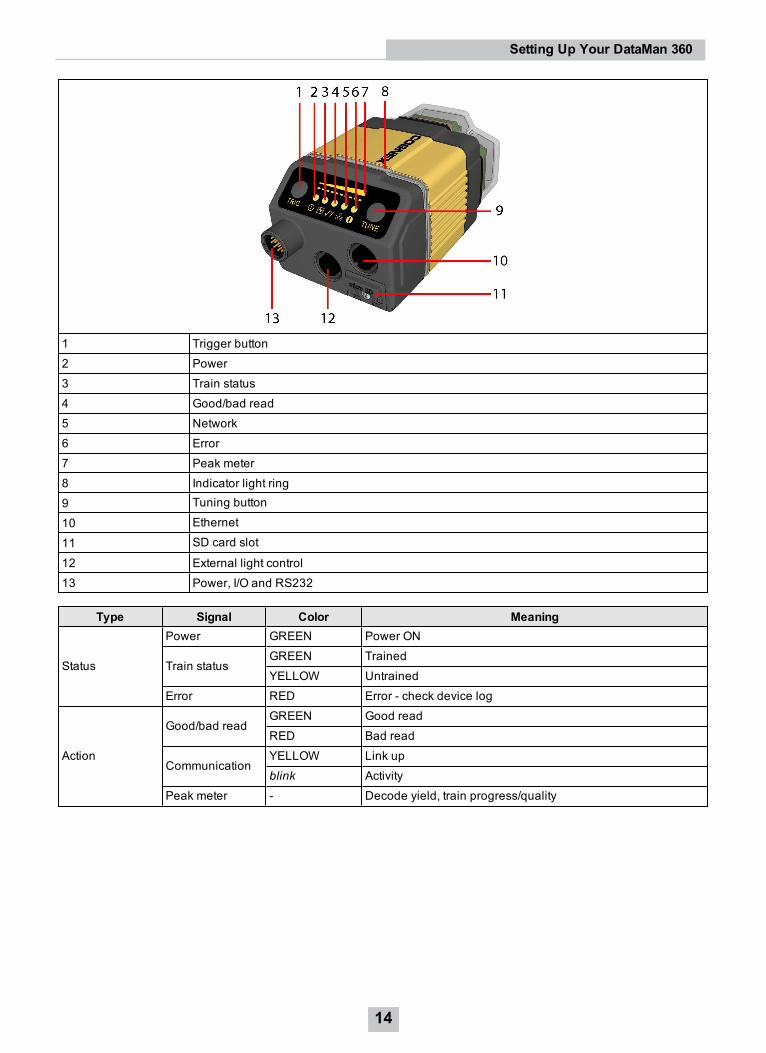
1 Trigger button2 Power3 Train status4 Good/bad read5 Network6 Error7 Peak meter8 Indicator light ring9 Tuning button
10 Ethernet
11 SD card slot
12 External light control13 Power, I/O and RS232
Type Signal Color Meaning
Status
Power GREEN Power ON
Train statusGREEN TrainedYELLOW Untrained
Error RED Error - check device log
Action
Good/bad readGREEN Good readRED Bad read
CommunicationYELLOW Link upblink Activity
Peak meter - Decode yield, train progress/quality
14
Setting Up Your DataMan 360
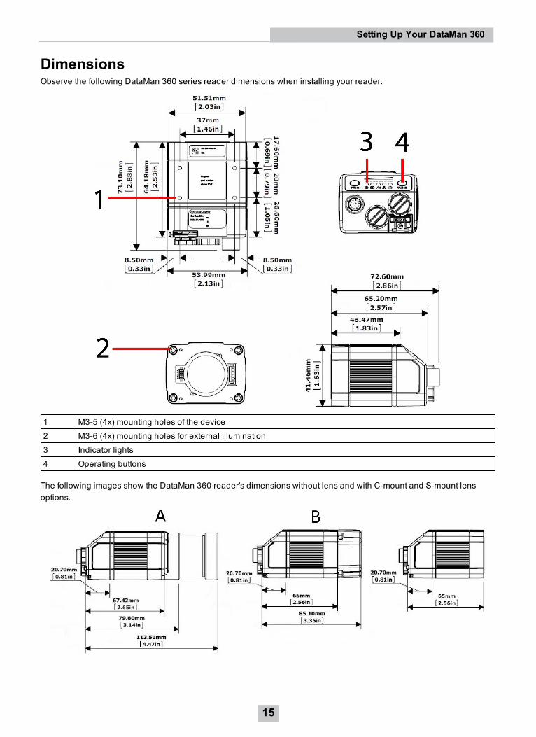
DimensionsObserve the following DataMan 360 series reader dimensions when installing your reader.
1 M3-5 (4x) mounting holes of the device2 M3-6 (4x) mounting holes for external illumination3 Indicator lights4 Operating buttons
The following images show the DataMan 360 reader's dimensions without lens and with C-mount and S-mount lensoptions.
15
Setting Up Your DataMan 360

A C-Mount Lens versionB S-Mount (M12) Lens version
16
Setting Up Your DataMan 360
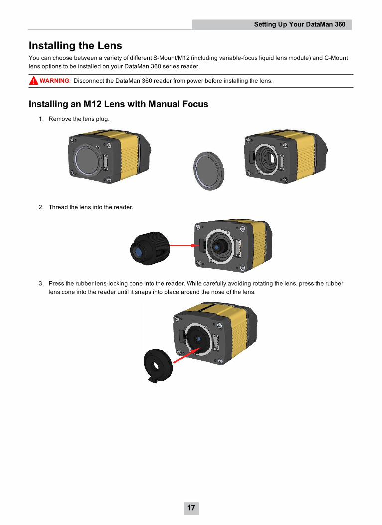
Installing the LensYou can choose between a variety of different S-Mount/M12 (including variable-focus liquid lens module) and C-Mountlens options to be installed on your DataMan 360 series reader.
WARNING: Disconnect the DataMan 360 reader from power before installing the lens.
Installing an M12 Lens with Manual Focus1. Remove the lens plug.
2. Thread the lens into the reader.
3. Press the rubber lens-locking cone into the reader. While carefully avoiding rotating the lens, press the rubberlens cone into the reader until it snaps into place around the nose of the lens.
17
Setting Up Your DataMan 360
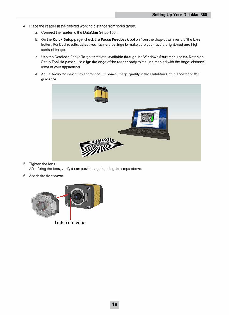
4. Place the reader at the desired working distance from focus target.
a. Connect the reader to the DataMan Setup Tool.
b. On the Quick Setup page, check the Focus Feedback option from the drop-down menu of the Livebutton. For best results, adjust your camera settings to make sure you have a brightened and highcontrast image.
c. Use the DataMan Focus Target template, available through the Windows Start menu or the DataManSetup Tool Helpmenu, to align the edge of the reader body to the line marked with the target distanceused in your application.
d. Adjust focus for maximum sharpness. Enhance image quality in the DataMan Setup Tool for betterguidance.
5. Tighten the lens.After fixing the lens, verify focus position again, using the steps above.
6. Attach the front cover.
18
Setting Up Your DataMan 360
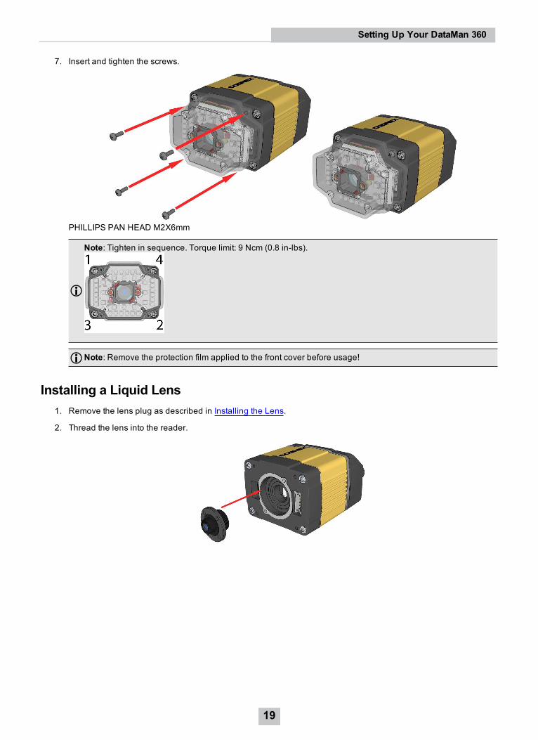
7. Insert and tighten the screws.
PHILLIPS PAN HEAD M2X6mm
Note: Tighten in sequence. Torque limit: 9 Ncm (0.8 in-lbs).
Note: Remove the protection film applied to the front cover before usage!
Installing a Liquid Lens1. Remove the lens plug as described in Installing the Lens.
2. Thread the lens into the reader.
19
Setting Up Your DataMan 360
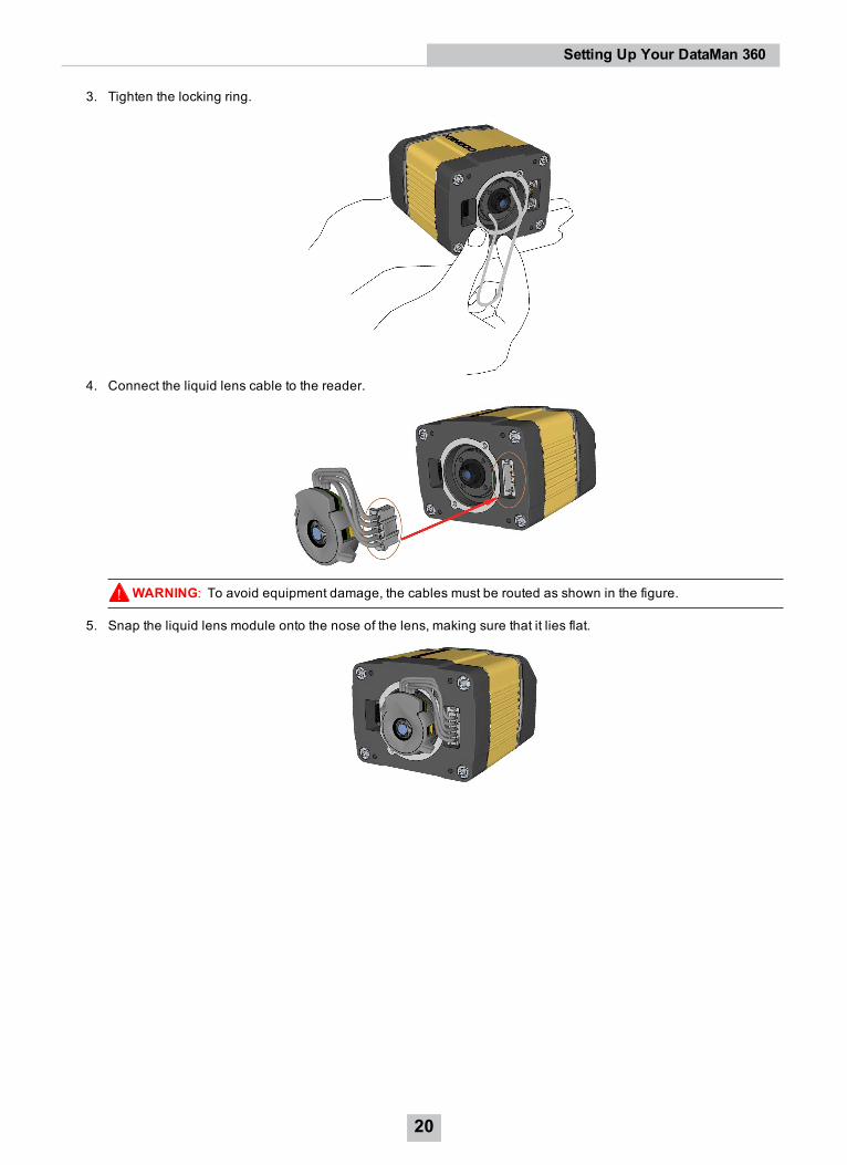
3. Tighten the locking ring.
4. Connect the liquid lens cable to the reader.
WARNING: To avoid equipment damage, the cables must be routed as shown in the figure.
5. Snap the liquid lens module onto the nose of the lens, making sure that it lies flat.
20
Setting Up Your DataMan 360
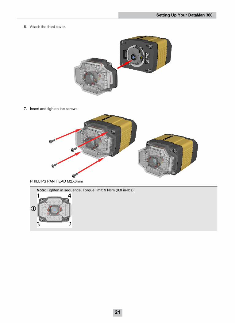
6. Attach the front cover.
7. Insert and tighten the screws.
PHILLIPS PAN HEAD M2X6mm
Note: Tighten in sequence. Torque limit: 9 Ncm (0.8 in-lbs).
21
Setting Up Your DataMan 360
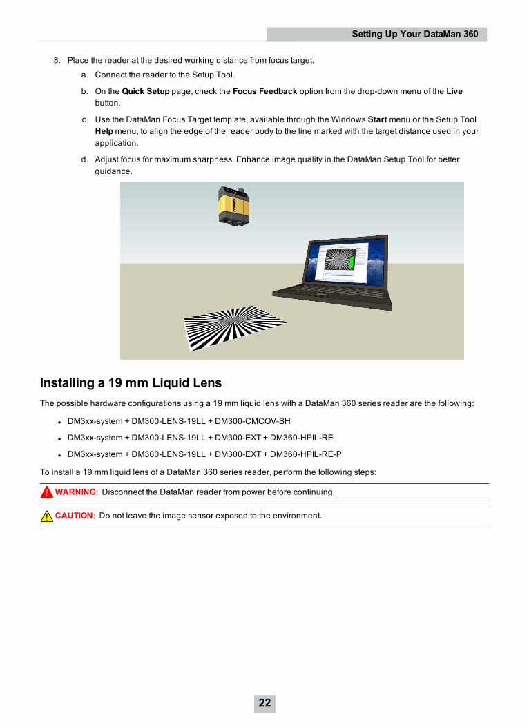
8. Place the reader at the desired working distance from focus target.
a. Connect the reader to the Setup Tool.
b. On the Quick Setup page, check the Focus Feedback option from the drop-down menu of the Livebutton.
c. Use the DataMan Focus Target template, available through the Windows Start menu or the Setup ToolHelpmenu, to align the edge of the reader body to the line marked with the target distance used in yourapplication.
d. Adjust focus for maximum sharpness. Enhance image quality in the DataMan Setup Tool for betterguidance.
Installing a 19 mm Liquid LensThe possible hardware configurations using a 19 mm liquid lens with a DataMan 360 series reader are the following:
l DM3xx-system + DM300-LENS-19LL + DM300-CMCOV-SH
l DM3xx-system + DM300-LENS-19LL + DM300-EXT + DM360-HPIL-RE
l DM3xx-system + DM300-LENS-19LL + DM300-EXT + DM360-HPIL-RE-P
To install a 19 mm liquid lens of a DataMan 360 series reader, perform the following steps:
WARNING: Disconnect the DataMan reader from power before continuing.
CAUTION: Do not leave the image sensor exposed to the environment.
22
Setting Up Your DataMan 360
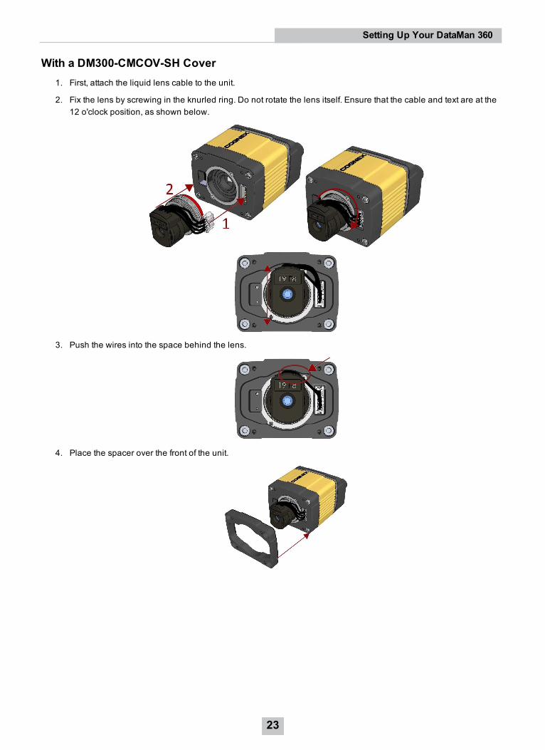
With a DM300-CMCOV-SH Cover1. First, attach the liquid lens cable to the unit.
2. Fix the lens by screwing in the knurled ring. Do not rotate the lens itself. Ensure that the cable and text are at the12 o'clock position, as shown below.
3. Push the wires into the space behind the lens.
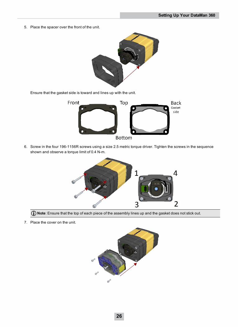
4. Place the spacer over the front of the unit.
23
Setting Up Your DataMan 360
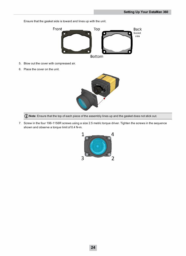
Ensure that the gasket side is toward and lines up with the unit.
5. Blow out the cover with compressed air.
6. Place the cover on the unit.
Note: Ensure that the top of each piece of the assembly lines up and the gasket does not stick out.
7. Screw in the four 196-1156R screws using a size 2.5 metric torque driver. Tighten the screws in the sequenceshown and observe a torque limit of 0.4 N-m.
24
Setting Up Your DataMan 360
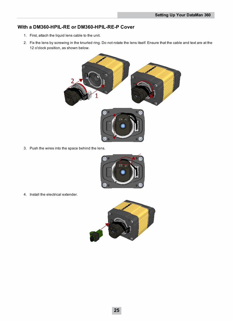
With a DM360-HPIL-RE or DM360-HPIL-RE-P Cover1. First, attach the liquid lens cable to the unit.
2. Fix the lens by screwing in the knurled ring. Do not rotate the lens itself. Ensure that the cable and text are at the12 o'clock position, as shown below.
3. Push the wires into the space behind the lens.
4. Install the electrical extender.
25
Setting Up Your DataMan 360
5. Place the spacer over the front of the unit.
Ensure that the gasket side is toward and lines up with the unit.
6. Screw in the four 196-1156R screws using a size 2.5 metric torque driver. Tighten the screws in the sequenceshown and observe a torque limit of 0.4 N-m.
Note: Ensure that the top of each piece of the assembly lines up and the gasket does not stick out.
7. Place the cover on the unit.
26
Setting Up Your DataMan 360
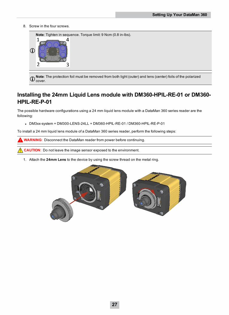
8. Screw in the four screws.
Note: Tighten in sequence. Torque limit: 9 Ncm (0.8 in-lbs).
Note: The protection foil must be removed from both light (outer) and lens (center) foils of the polarizedcover.
Installing the 24mm Liquid Lens module with DM360-HPIL-RE-01 or DM360-HPIL-RE-P-01The possible hardware configurations using a 24 mm liquid lens module with a DataMan 360 series reader are thefollowing:
l DM3xx-system + DM300-LENS-24LL + DM360-HPIL-RE-01 / DM360-HPIL-RE-P-01
To install a 24 mm liquid lens module of a DataMan 360 series reader, perform the following steps:
WARNING: Disconnect the DataMan reader from power before continuing.
CAUTION: Do not leave the image sensor exposed to the environment.
1. Attach the 24mm Lens to the device by using the screw thread on the metal ring.
27
Setting Up Your DataMan 360
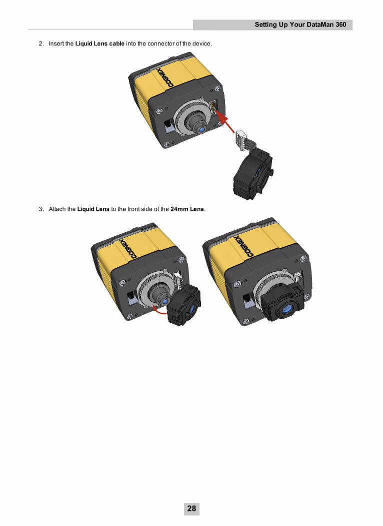
2. Insert the Liquid Lens cable into the connector of the device.
3. Attach the Liquid Lens to the front side of the 24mm Lens.
28
Setting Up Your DataMan 360
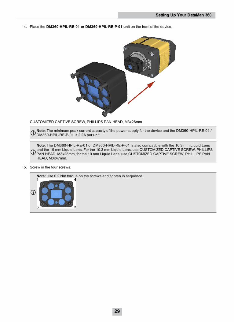
4. Place the DM360-HPIL-RE-01 or DM360-HPIL-RE-P-01 unit on the front of the device.
CUSTOMIZED CAPTIVE SCREW, PHILLIPS PAN HEAD, M3x28mm
Note: The minimum peak current capacity of the power supply for the device and the DM360-HPIL-RE-01 /DM360-HPIL-RE-P-01 is 2.2A per unit.
Note: The DM360-HPIL-RE-01 or DM360-HPIL-RE-P-01 is also compatible with the 10.3 mm Liquid Lensand the 19 mm Liquid Lens. For the 10.3 mm Liquid Lens, use CUSTOMIZED CAPTIVE SCREW, PHILLIPSPAN HEAD, M3x28mm, for the 19 mm Liquid Lens, use CUSTOMIZED CAPTIVE SCREW, PHILLIPS PANHEAD, M3x47mm.
5. Screw in the four screws.
Note: Use 0.2 Nm torque on the screws and tighten in sequence.
29
Setting Up Your DataMan 360
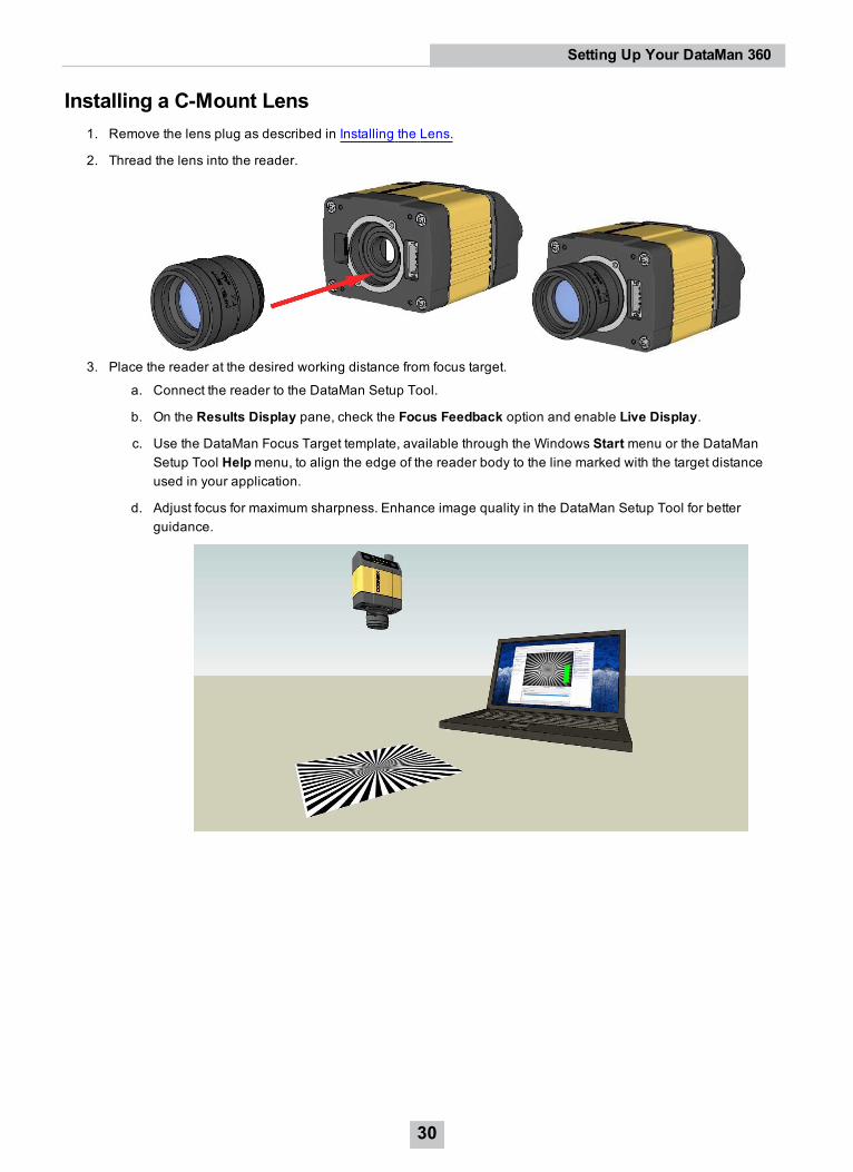
Installing a C-Mount Lens1. Remove the lens plug as described in Installing the Lens.
2. Thread the lens into the reader.
3. Place the reader at the desired working distance from focus target.
a. Connect the reader to the DataMan Setup Tool.
b. On the Results Display pane, check the Focus Feedback option and enable Live Display.
c. Use the DataMan Focus Target template, available through the Windows Start menu or the DataManSetup Tool Helpmenu, to align the edge of the reader body to the line marked with the target distanceused in your application.
d. Adjust focus for maximum sharpness. Enhance image quality in the DataMan Setup Tool for betterguidance.
30
Setting Up Your DataMan 360
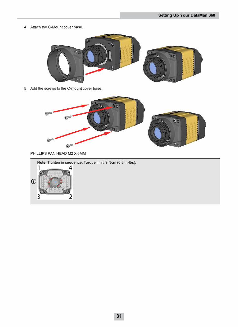
4. Attach the C-Mount cover base.
5. Add the screws to the C-mount cover base.
PHILLIPS PAN HEAD M2 X 6MM
Note: Tighten in sequence. Torque limit: 9 Ncm (0.8 in-lbs).
31
Setting Up Your DataMan 360
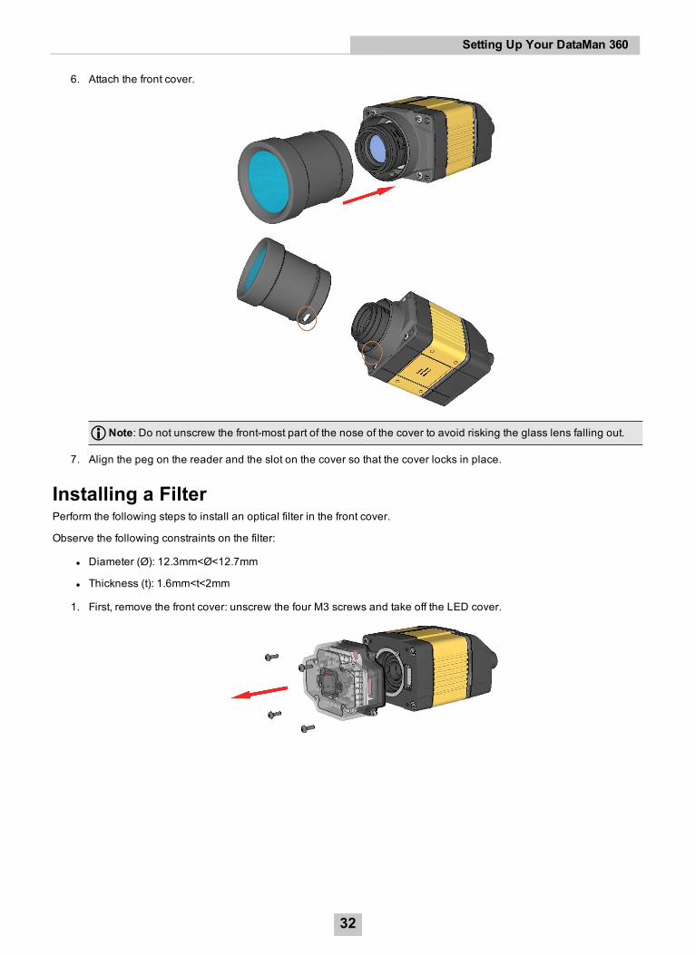
6. Attach the front cover.
Note: Do not unscrew the front-most part of the nose of the cover to avoid risking the glass lens falling out.
7. Align the peg on the reader and the slot on the cover so that the cover locks in place.
Installing a FilterPerform the following steps to install an optical filter in the front cover.
Observe the following constraints on the filter:
l Diameter (Ø): 12.3mm<Ø<12.7mm
l Thickness (t): 1.6mm<t<2mm
1. First, remove the front cover: unscrew the four M3 screws and take off the LED cover.
32
Setting Up Your DataMan 360
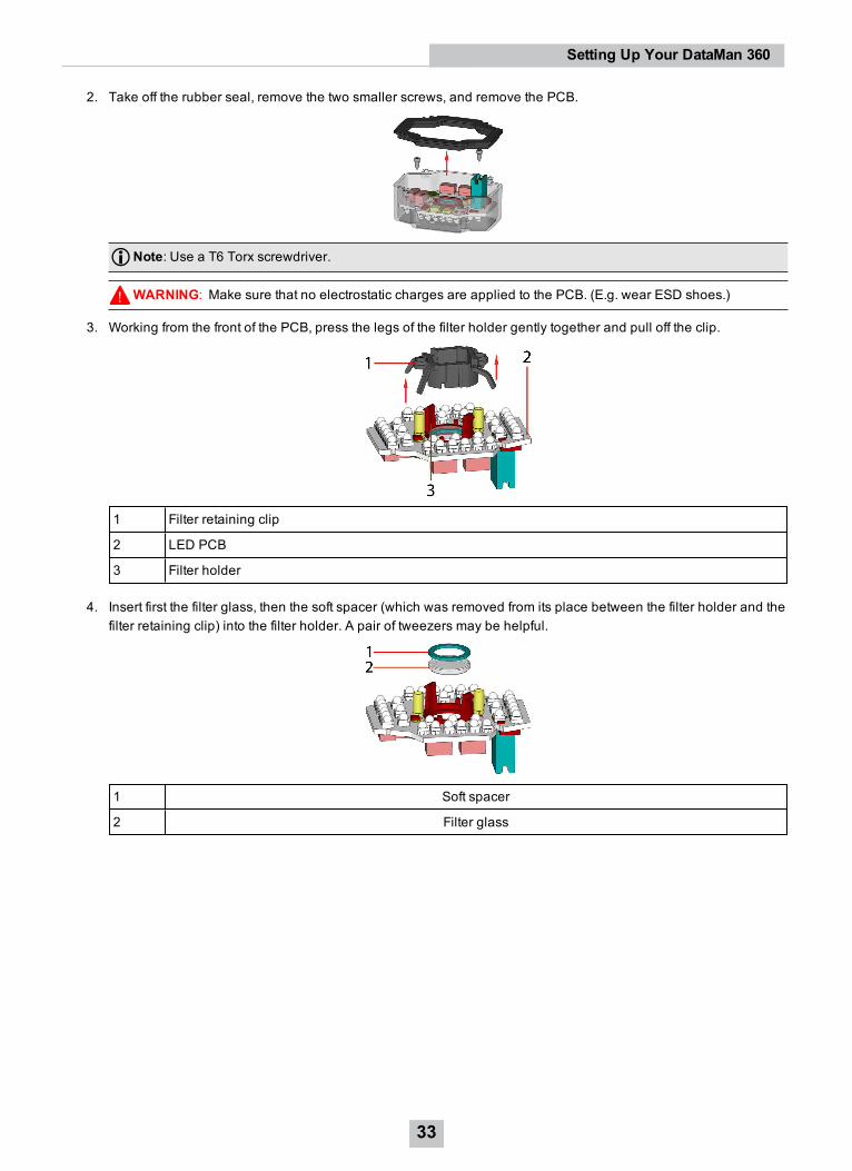
2. Take off the rubber seal, remove the two smaller screws, and remove the PCB.
Note: Use a T6 Torx screwdriver.
WARNING: Make sure that no electrostatic charges are applied to the PCB. (E.g. wear ESD shoes.)
3. Working from the front of the PCB, press the legs of the filter holder gently together and pull off the clip.
1 Filter retaining clip
2 LED PCB
3 Filter holder
4. Insert first the filter glass, then the soft spacer (which was removed from its place between the filter holder and thefilter retaining clip) into the filter holder. A pair of tweezers may be helpful.
1 Soft spacer
2 Filter glass
33
Setting Up Your DataMan 360
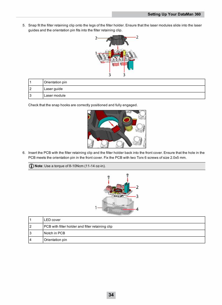
5. Snap fit the filter retaining clip onto the legs of the filter holder. Ensure that the laser modules slide into the laserguides and the orientation pin fits into the filter retaining clip.
1 Orientation pin
2 Laser guide
3 Laser module
Check that the snap hooks are correctly positioned and fully engaged.
6. Insert the PCB with the filter retaining clip and the filter holder back into the front cover. Ensure that the hole in thePCB meets the orientation pin in the front cover. Fix the PCB with two Torx 6 screws of size 2.0x5 mm.
Note: Use a torque of 8-10Ncm (11-14 oz-in).
1 LED cover
2 PCB with filter holder and filter retaining clip
3 Notch in PCB
4 Orientation pin
34
Setting Up Your DataMan 360
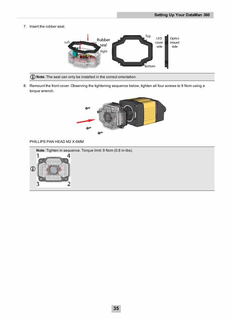
7. Insert the rubber seal.
Note: The seal can only be installed in the correct orientation.
8. Remount the front cover. Observing the tightening sequence below, tighten all four screws to 9 Ncm using atorque wrench.
PHILLIPS PAN HEAD M2 X 6MM
Note: Tighten in sequence. Torque limit: 9 Ncm (0.8 in-lbs).
35
Setting Up Your DataMan 360
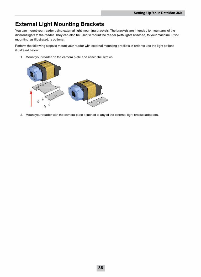
External Light Mounting BracketsYou can mount your reader using external light mounting brackets. The brackets are intended to mount any of thedifferent lights to the reader. They can also be used to mount the reader (with lights attached) to your machine. Pivotmounting, as illustrated, is optional.
Perform the following steps to mount your reader with external mounting brackets in order to use the light optionsillustrated below:
1. Mount your reader on the camera plate and attach the screws.
2. Mount your reader with the camera plate attached to any of the external light bracket adapters.
36
Setting Up Your DataMan 360
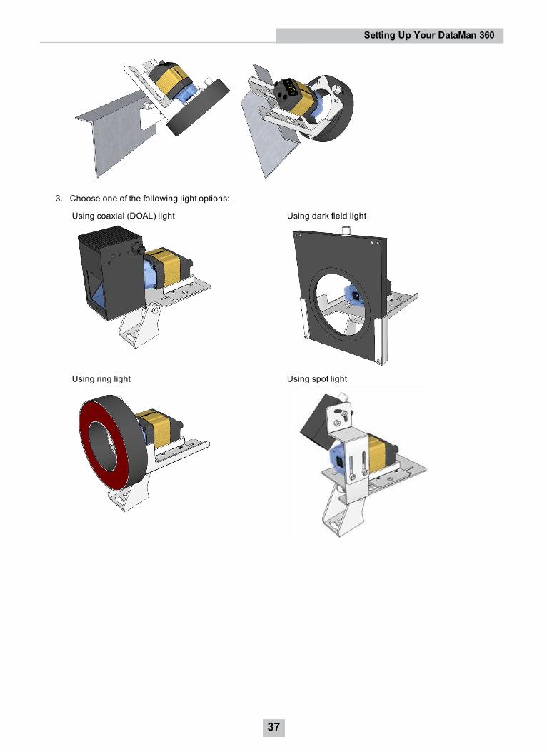
3. Choose one of the following light options:
Using coaxial (DOAL) light Using dark field light
Using ring light Using spot light
37
Setting Up Your DataMan 360
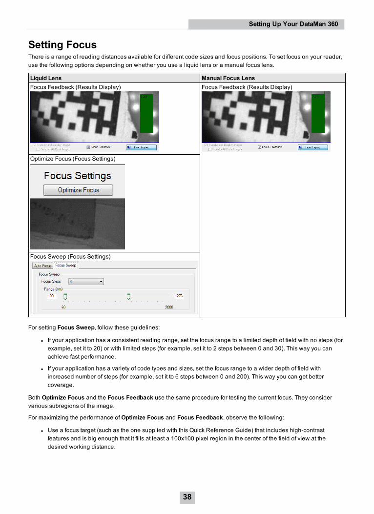
Setting FocusThere is a range of reading distances available for different code sizes and focus positions. To set focus on your reader,use the following options depending on whether you use a liquid lens or a manual focus lens.
Liquid Lens Manual Focus LensFocus Feedback (Results Display) Focus Feedback (Results Display)
Optimize Focus (Focus Settings)
Focus Sweep (Focus Settings)
For setting Focus Sweep, follow these guidelines:
l If your application has a consistent reading range, set the focus range to a limited depth of field with no steps (forexample, set it to 20) or with limited steps (for example, set it to 2 steps between 0 and 30). This way you canachieve fast performance.
l If your application has a variety of code types and sizes, set the focus range to a wider depth of field withincreased number of steps (for example, set it to 6 steps between 0 and 200). This way you can get bettercoverage.
Both Optimize Focus and the Focus Feedback use the same procedure for testing the current focus. They considervarious subregions of the image.
For maximizing the performance ofOptimize Focus and Focus Feedback, observe the following:
l Use a focus target (such as the one supplied with this Quick Reference Guide) that includes high-contrastfeatures and is big enough that it fills at least a 100x100 pixel region in the center of the field of view at thedesired working distance.
38
Setting Up Your DataMan 360
l Make sure the target is perfectly flat (avoid floppy pieces of paper).
l Make sure that the target is perfectly perpendicular to the optical axis of the reader.
l Make sure that the rest of the field of view (such as the part not covered by the focus target) does not contain anyhigh-contrast features. For example, you would ideally fill the entire field of view with a white card or sheet ofpaper (no shadows), then position the focus target in the middle.
l The supplied focus target (120x120mm) is appropriate for typical working distances. If you are using a workingdistance such that the target does not completely fill the image, make sure that there are no high-contrast featuresvisible outside of the target (see previous bullet).
Note:l If you are using the focus feedback indicator to adjust a manual focus lens, you must apply power to thereader before you remove the cover. If you remove the cover before applying power, the internal illuminationwill not function.
l If you are using a Liquid Lens, make sure that the cover is mounted and connected before you apply power.If you attach or remove the front cover while the reader is powered, the focus settings will be lost.
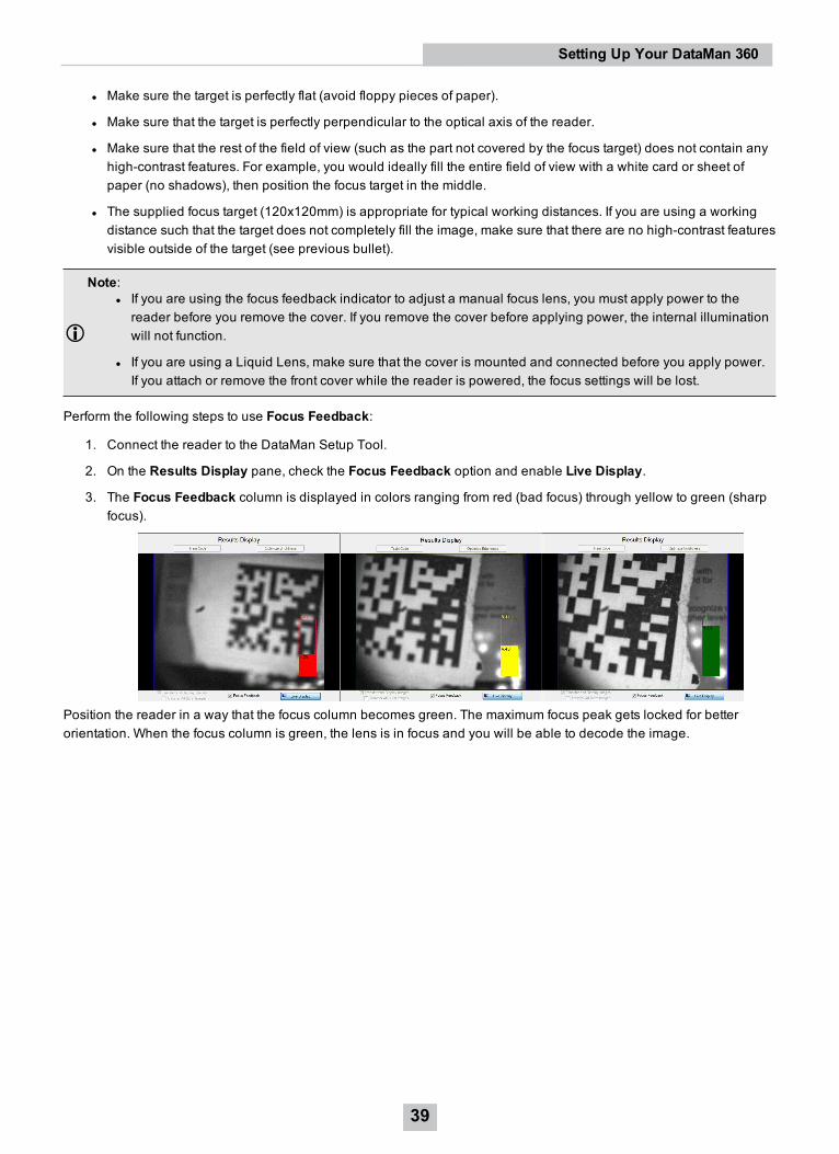
Perform the following steps to use Focus Feedback:
1. Connect the reader to the DataMan Setup Tool.
2. On the Results Display pane, check the Focus Feedback option and enable Live Display.
3. The Focus Feedback column is displayed in colors ranging from red (bad focus) through yellow to green (sharpfocus).
Position the reader in a way that the focus column becomes green. The maximum focus peak gets locked for betterorientation. When the focus column is green, the lens is in focus and you will be able to decode the image.
39
Setting Up Your DataMan 360
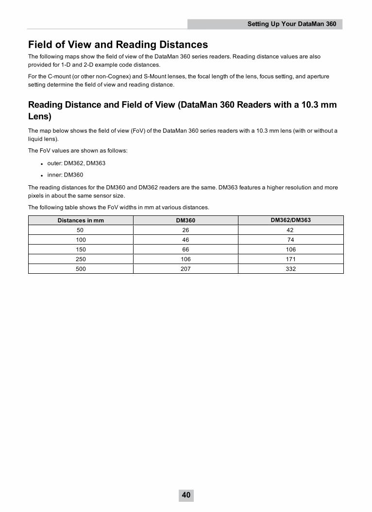
Field of View and Reading DistancesThe following maps show the field of view of the DataMan 360 series readers. Reading distance values are alsoprovided for 1-D and 2-D example code distances.
For the C-mount (or other non-Cognex) and S-Mount lenses, the focal length of the lens, focus setting, and aperturesetting determine the field of view and reading distance.
Reading Distance and Field of View (DataMan 360 Readers with a 10.3 mmLens)The map below shows the field of view (FoV) of the DataMan 360 series readers with a 10.3 mm lens (with or without aliquid lens).
The FoV values are shown as follows:
l outer: DM362, DM363
l inner: DM360
The reading distances for the DM360 and DM362 readers are the same. DM363 features a higher resolution and morepixels in about the same sensor size.
The following table shows the FoV widths in mm at various distances.
Distances in mm DM360 DM362/DM36350 26 42100 46 74150 66 106250 106 171500 207 332
40
Setting Up Your DataMan 360
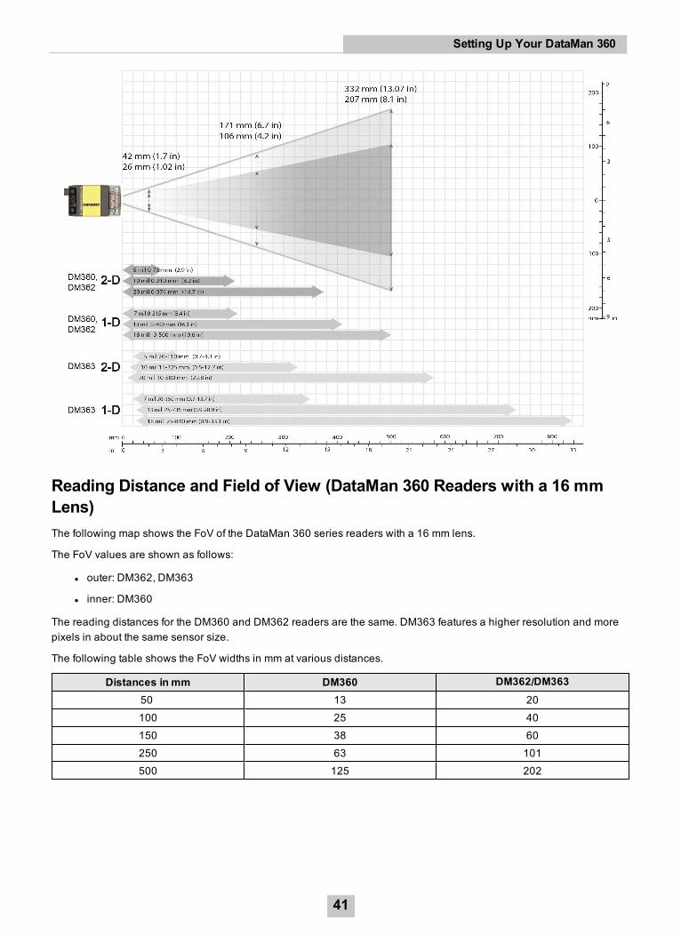
Reading Distance and Field of View (DataMan 360 Readers with a 16 mmLens)The following map shows the FoV of the DataMan 360 series readers with a 16 mm lens.
The FoV values are shown as follows:
l outer: DM362, DM363
l inner: DM360
The reading distances for the DM360 and DM362 readers are the same. DM363 features a higher resolution and morepixels in about the same sensor size.
The following table shows the FoV widths in mm at various distances.
Distances in mm DM360 DM362/DM36350 13 20100 25 40150 38 60250 63 101500 125 202
41
Setting Up Your DataMan 360
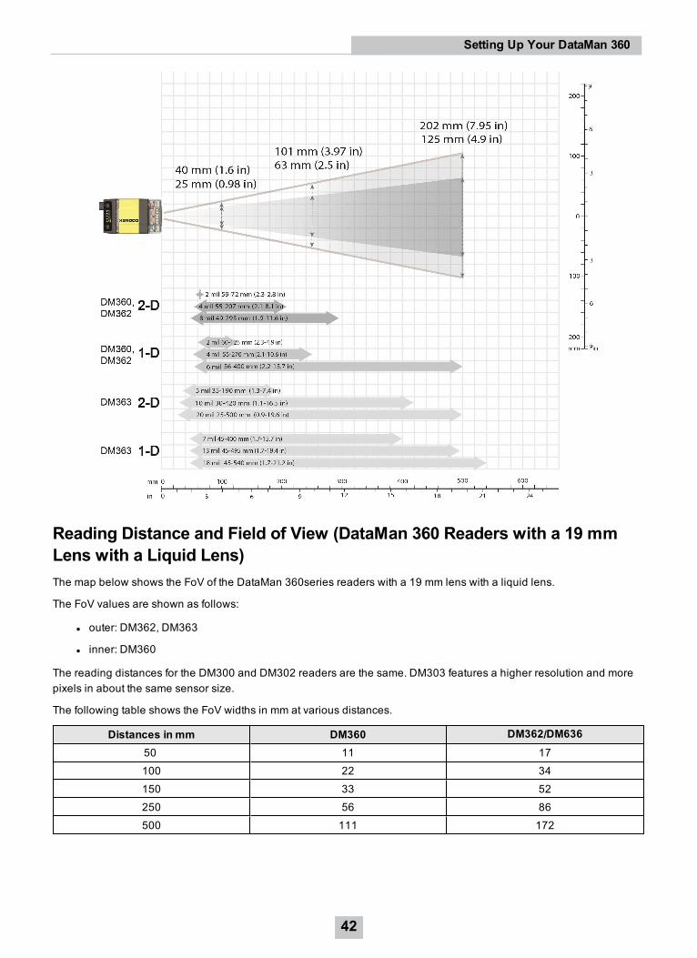
Reading Distance and Field of View (DataMan 360 Readers with a 19 mmLens with a Liquid Lens)The map below shows the FoV of the DataMan 360series readers with a 19 mm lens with a liquid lens.
The FoV values are shown as follows:
l outer: DM362, DM363
l inner: DM360
The reading distances for the DM300 and DM302 readers are the same. DM303 features a higher resolution and morepixels in about the same sensor size.
The following table shows the FoV widths in mm at various distances.
Distances in mm DM360 DM362/DM63650 11 17100 22 34150 33 52250 56 86500 111 172
42
Setting Up Your DataMan 360

Reading Distance and Field of View (DataMan 360 Readers with a 24 mmLens with Liquid Lens)The following map shows the FoV of the DataMan 360 series readers with a 24 mm lens with a liquid lens and DM360-HPIL-RE-01 or DM360-HPIL-RE-P-01 cover.
The FoV values are shown as follows:
l outer: DM363
l middle: DM362
l inner: DM360
The reading distances for the DM360 and DM362readers are the same. DM363 features a higher resolution and morepixels in about the same sensor size.
The following table shows the FoV widths in mm at various distances.
Distances in mm DM360 DM362 DM36380 11 19 20
43
Setting Up Your DataMan 360
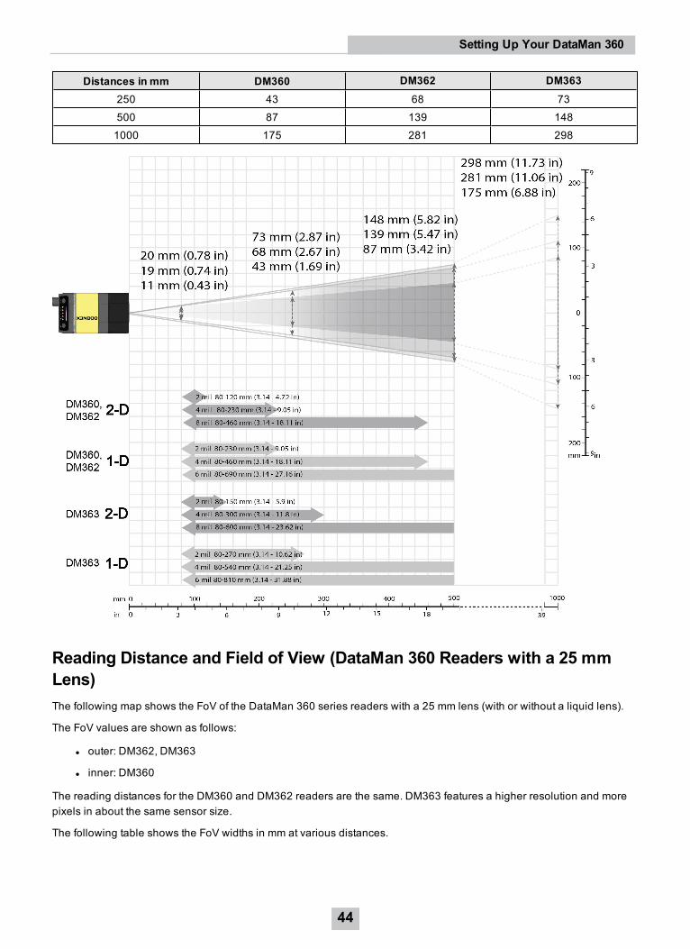
Distances in mm DM360 DM362 DM363250 43 68 73500 87 139 1481000 175 281 298
Reading Distance and Field of View (DataMan 360 Readers with a 25 mmLens)The following map shows the FoV of the DataMan 360 series readers with a 25 mm lens (with or without a liquid lens).
The FoV values are shown as follows:
l outer: DM362, DM363
l inner: DM360
The reading distances for the DM360 and DM362 readers are the same. DM363 features a higher resolution and morepixels in about the same sensor size.
The following table shows the FoV widths in mm at various distances.
44
Setting Up Your DataMan 360
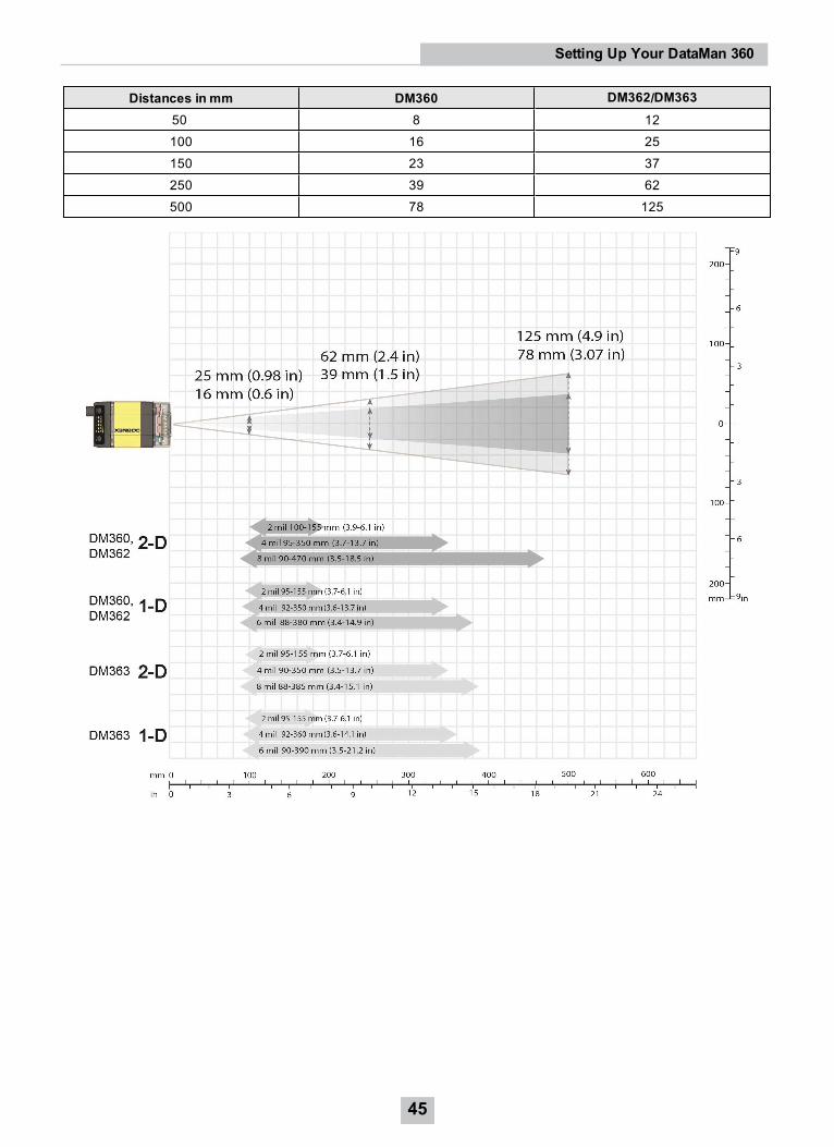
Distances in mm DM360 DM362/DM36350 8 12100 16 25150 23 37250 39 62500 78 125
45
Setting Up Your DataMan 360
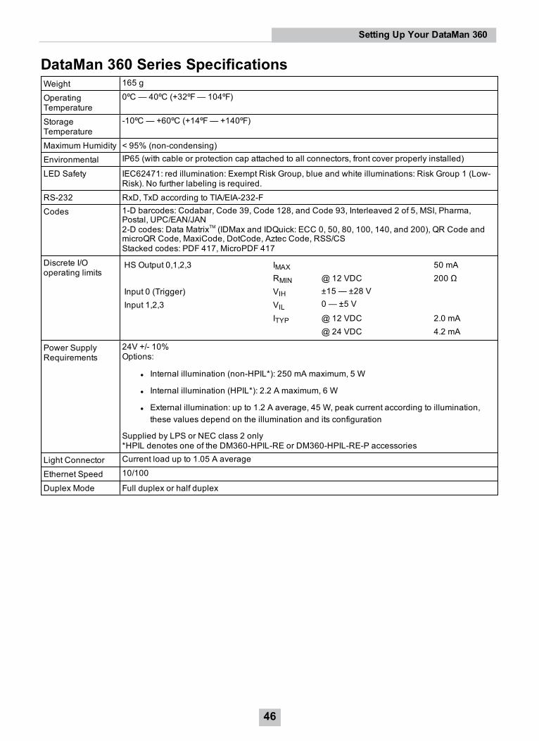
DataMan 360 Series SpecificationsWeight 165 g
OperatingTemperature
0ºC — 40ºC (+32ºF— 104ºF)
StorageTemperature
-10ºC — +60ºC (+14ºF— +140ºF)
Maximum Humidity < 95% (non-condensing)Environmental IP65 (with cable or protection cap attached to all connectors, front cover properly installed)
LED Safety IEC62471: red illumination: Exempt Risk Group, blue and white illuminations: Risk Group 1 (Low-Risk). No further labeling is required.
RS-232 RxD, TxD according to TIA/EIA-232-FCodes 1-D barcodes: Codabar, Code 39, Code 128, and Code 93, Interleaved 2 of 5, MSI, Pharma,
Postal, UPC/EAN/JAN2-D codes: Data MatrixTM (IDMax and IDQuick: ECC 0, 50, 80, 100, 140, and 200), QR Code andmicroQR Code, MaxiCode, DotCode, Aztec Code, RSS/CSStacked codes: PDF 417, MicroPDF 417
Discrete I/Ooperating limits
HS Output 0,1,2,3 IMAX 50 mARMIN @12 VDC 200 Ω
Input 0 (Trigger) VIH ±15 — ±28 VInput 1,2,3 VIL 0 — ±5 V
ITYP @12 VDC 2.0 mA@ 24 VDC 4.2 mA
Power SupplyRequirements
24V +/- 10%Options:
l Internal illumination (non-HPIL*): 250 mA maximum, 5 W
l Internal illumination (HPIL*): 2.2 A maximum, 6 W
l External illumination: up to 1.2 A average, 45 W, peak current according to illumination,these values depend on the illumination and its configuration
Supplied by LPS or NEC class 2 only*HPIL denotes one of the DM360-HPIL-RE or DM360-HPIL-RE-P accessories
Light Connector Current load up to 1.05 A average
Ethernet Speed 10/100
Duplex Mode Full duplex or half duplex
46
Setting Up Your DataMan 360
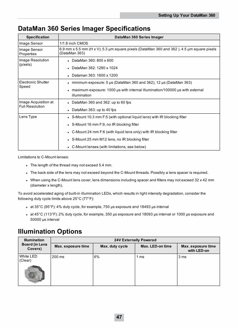
DataMan 360 Series Imager SpecificationsSpecification DataMan 360 Series Imager
Image Sensor 1/1.8 inch CMOSImage SensorProperties
6.9 mm x 5.5 mm (H x V); 5.3 µm square pixels (DataMan 360 and 362 ), 4.5 µm square pixels(DataMan 363)
Image Resolution(pixels)
l DataMan 360: 800 x 600
l DataMan 362: 1280 x 1024
l Dataman 363: 1600 x 1200
Electronic ShutterSpeed
l minimum exposure: 5 µs (DataMan 360 and 362), 12 µs (DataMan 363)
l maximum exposure: 1000 µs with internal illumination/100000 µs with externalillumination
Image Acquisition atFull Resolution
l DataMan 360 and 362: up to 60 fps
l DataMan 363: up to 40 fps
Lens Type l S-Mount 10.3 mm F:5 (with optional liquid lens) with IR blocking filter
l S-Mount 16 mm F:9, no IR blocking filter
l C-Mount 24 mm F:6 (with liquid lens only) with IR blocking filter
l S-Mount 25 mm M12 lens, no IR blocking filter
l C-Mount lenses (with limitations, see below)
Limitations to C-Mount lenses:
l The length of the thread may not exceed 5.4 mm.
l The back side of the lens may not exceed beyond the C-Mount threads. Possibly a lens spacer is required.
l When using the C-Mount lens cover, lens dimensions including spacer and filters may not exceed 32 x 42 mm(diameter x length).
To avoid accelerated aging of built-in illumination LEDs, which results in light intensity degradation, consider thefollowing duty cycle limits above 25°C (77°F):
l at 35°C (95°F): 4% duty cycle, for example, 750 µs exposure and 18493 µs interval
l at 45°C (113°F): 2% duty cycle, for example, 350 µs exposure and 18093 µs interval or 1000 µs exposure and50000 µs interval
Illumination OptionsIllumination
Board (in LensCovers)
24V Externally PoweredMax. exposure time Max. duty cycle Max. LED-on time Max. exposure time
with LED-onWhite LED(Clear)
200 ms 6% 1 ms 3 ms
47
Setting Up Your DataMan 360
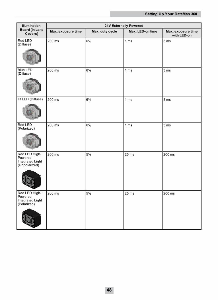
IlluminationBoard (in Lens
Covers)
24V Externally PoweredMax. exposure time Max. duty cycle Max. LED-on time Max. exposure time
with LED-onRed LED(Diffuse)
200 ms 6% 1 ms 3 ms
Blue LED(Diffuse)
200 ms 6% 1 ms 3 ms
IR LED (Diffuse) 200 ms 6% 1 ms 3 ms
Red LED(Polarized)
200 ms 6% 1 ms 3 ms
Red LED High-PoweredIntegrated Light(Unpolarized)
200 ms 5% 25 ms 200 ms
Red LED High-PoweredIntegrated Light(Polarized)
200 ms 5% 25 ms 200 ms
48
Setting Up Your DataMan 360
Using Your DataMan 360This section provides information on the installation process of the DataMan Setup Tool, troubleshooting Ethernetconnection issues, tuning, image filtering, as well as reader training and package detection.
Installing DataMan Software and Connecting the ReaderFollow the steps below to install and connect your reader to the DataMan Setup Tool:
1. Check the DataMan Release Notes for a full list of system requirements.
2. Download the DataMan Setup Tool from http://www.cognex.com/support/dataman and follow the on-screensteps.
3. Connect the DataMan 360 Series reader to your PC.
4. Launch the DataMan Setup Tool and click Refresh.Detected readers will appear under COM ports or Network devices, or both.
5. Select a reader from the list and click Connect.
WARNING: Do not stare into beam when adding, removing, or changing cables. Cognex recommends to unpowerthe reader any time you make physical changes to it.
Follow the steps below to connect your reader to power and network:
1. Connect the I/O+RS232+24V cable to your reader.
2. For a network connection, connect your reader, through an Ethernet cable, to your network.
3. Connect the cable to a 24V power supply.
Troubleshooting an Ethernet ConnectionBased on your network configuration, the DataMan Setup Tool may not be able to communicate with the reader and itwill not appear in the list of Network devices.
1. First, check your Ethernet connection with the reader and click Refresh in the DataMan Setup Tool.
2. Next, scan the Enable DHCP code in the Reader Configuration Codes document available from the Start menu.This might allow the reader to acquire a suitable IP address from a DHCP server on your subnet.
If the reader still does not appear, you can use either the Add Device or Force Network Settings options in theDataManSetup Tool.
For more information, see the DataMan Setup Tool Quick Reference Guide.
You can also use the RS-232 connection to configure the reader with parameters that allow it to communicate over yourEthernet network.
49
Using Your DataMan 360
Industrial ProtocolsThe DataMan 360 readers support the following industrial protocols:
l EtherNet/IP™
l PROFINET
l MC Protocol
l Modbus TCP
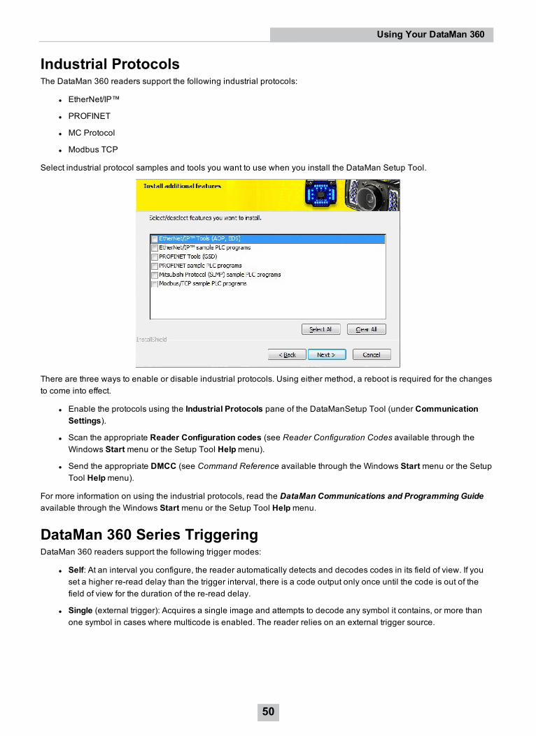
Select industrial protocol samples and tools you want to use when you install the DataMan Setup Tool.
There are three ways to enable or disable industrial protocols. Using either method, a reboot is required for the changesto come into effect.
l Enable the protocols using the Industrial Protocols pane of the DataManSetup Tool (under CommunicationSettings).
l Scan the appropriate Reader Configuration codes (see Reader Configuration Codes available through theWindows Start menu or the Setup Tool Helpmenu).
l Send the appropriate DMCC (see Command Reference available through the Windows Start menu or the SetupTool Helpmenu).
For more information on using the industrial protocols, read the DataMan Communications and Programming Guideavailable through the Windows Start menu or the Setup Tool Helpmenu.
DataMan 360 Series TriggeringDataMan 360 readers support the following trigger modes:
l Self: At an interval you configure, the reader automatically detects and decodes codes in its field of view. If youset a higher re-read delay than the trigger interval, there is a code output only once until the code is out of thefield of view for the duration of the re-read delay.
l Single (external trigger): Acquires a single image and attempts to decode any symbol it contains, or more thanone symbol in cases where multicode is enabled. The reader relies on an external trigger source.
50
Using Your DataMan 360

l Presentation: Scans, decodes and reports a single code in the field of view. The reader relies on an internaltiming mechanism to acquire images.
l Manual: Begins acquiring images when you press the trigger button on the reader, and continues acquiringimages until a symbol is found and decoded or you release the button.
l Burst: Performs multiple image acquisitions based on an external trigger and decodes any symbol appearing ina single image or within a sequence of images, or multiple symbols in a single image or within a sequence ofimages when multicode is enabled. You can control the number of images within each burst and the intervalbetween image acquisitions.
l Continuous: Begins acquiring images based on a single external trigger and continues to acquire and decodeimages until a symbol is found and decoded, or until multiple images containing as many codes as specified inmulticode mode are located, or until the trigger is released. You can configure your reader to acquire imagesbased on the start and stop signal from separate digital IO pulses.
In Single, Burst, Continuous, and Self trigger modes, it is possible to synchronize image acquisition on multipledevices using the synchronization interface. Synchronization allows using one shared strobe illumination to expose allsensors simultaneously. You can synchronize up to 16 readers, with optionally triggering them in a defined sequence toavoid that opposing readers blind each other. Note that this and other imager settings will not get synchronized by thismechanism - for example, you must configure exposure and gain on each reader individually. This feature onlysynchronizes the actual image acquisition, triggering happens through the existing master-slave mechanism.
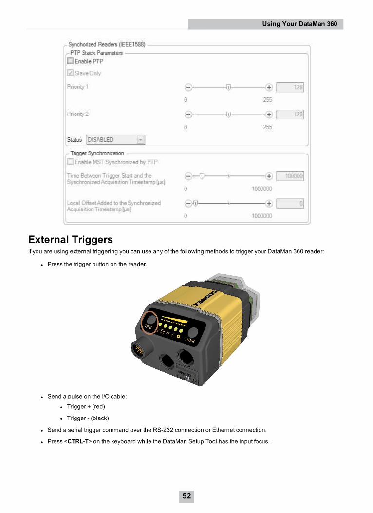
To set up synchronized acquisition on DataMan 360, enable PTP (Precision Time Protocol) on the Master/Slave pane ofthe DataMan Setup Tool under Synchronized Readers (IE1588). Set the Slave Only accordingly on each readerindividually to define Master/Slave reader relations.
The setting in 7 steps:
1. Check the Enable PTP check box.
2. Keep set the Slave Only check box if there is already a PTP master clock in the net (uncheck otherwise on at leastone reader)
3. Tune fine by Prioriry 1 and Priority 2
4. Status: Set the protocol state
5. Enable MST Sync by trigger: Use PTP to actually sync Master/Slave triggering
6. Time between Trigger Start and the Synchronized Acquisition Timestamp: Time the Master adds to the trigger tomake sure all devices already received the TCP package before this time stamp.
7. Local Offset Added to the Synchronized Acquisition Timestamp: Time the slave adds to the timestamp to realizeoffset image acquisitions.
51
Using Your DataMan 360
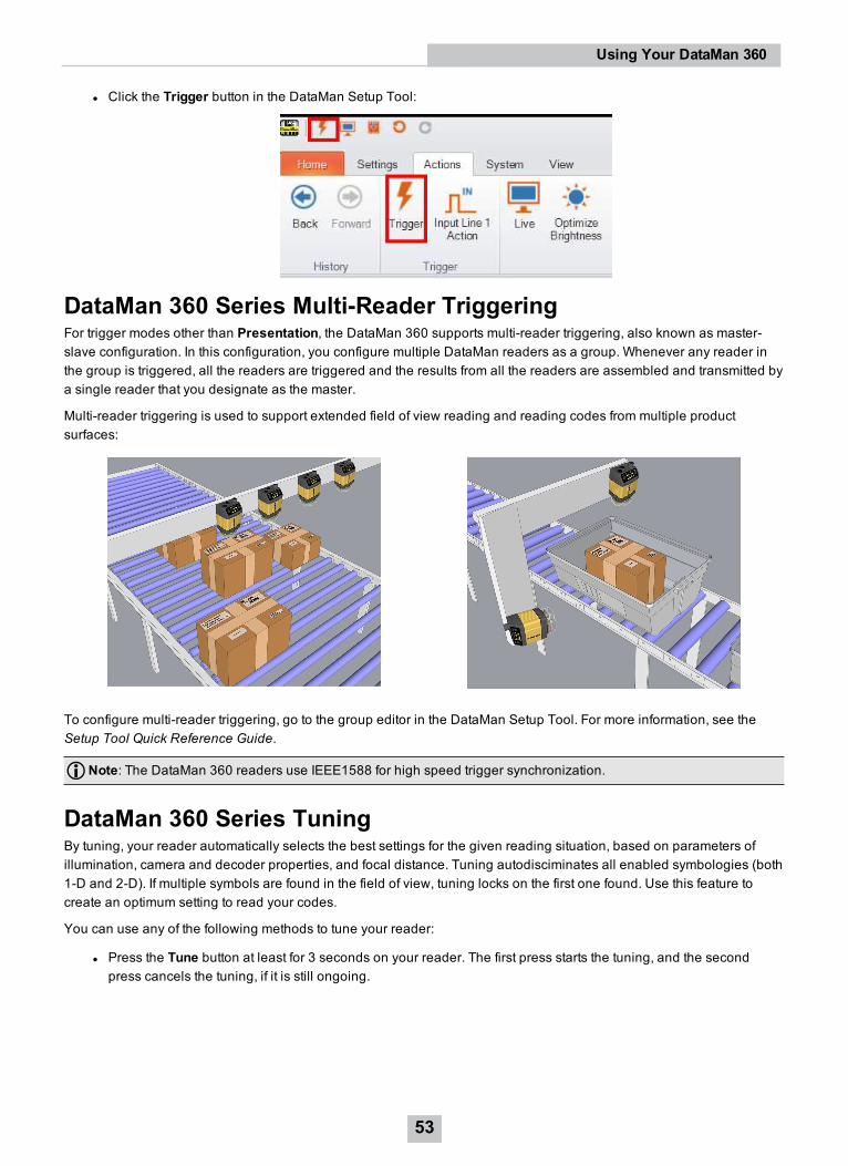
External TriggersIf you are using external triggering you can use any of the following methods to trigger your DataMan 360 reader:
l Press the trigger button on the reader.
l Send a pulse on the I/O cable:
l Trigger + (red)
l Trigger - (black)
l Send a serial trigger command over the RS-232 connection or Ethernet connection.
l Press <CTRL-T> on the keyboard while the DataMan Setup Tool has the input focus.
52
Using Your DataMan 360
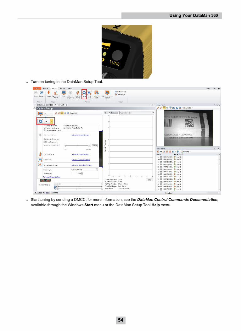
l Click the Trigger button in the DataMan Setup Tool:
DataMan 360 Series Multi-Reader TriggeringFor trigger modes other than Presentation, the DataMan 360 supports multi-reader triggering, also known as master-slave configuration. In this configuration, you configure multiple DataMan readers as a group. Whenever any reader inthe group is triggered, all the readers are triggered and the results from all the readers are assembled and transmitted bya single reader that you designate as the master.
Multi-reader triggering is used to support extended field of view reading and reading codes from multiple productsurfaces:
To configure multi-reader triggering, go to the group editor in the DataMan Setup Tool. For more information, see theSetup Tool Quick Reference Guide.
Note: The DataMan 360 readers use IEEE1588 for high speed trigger synchronization.
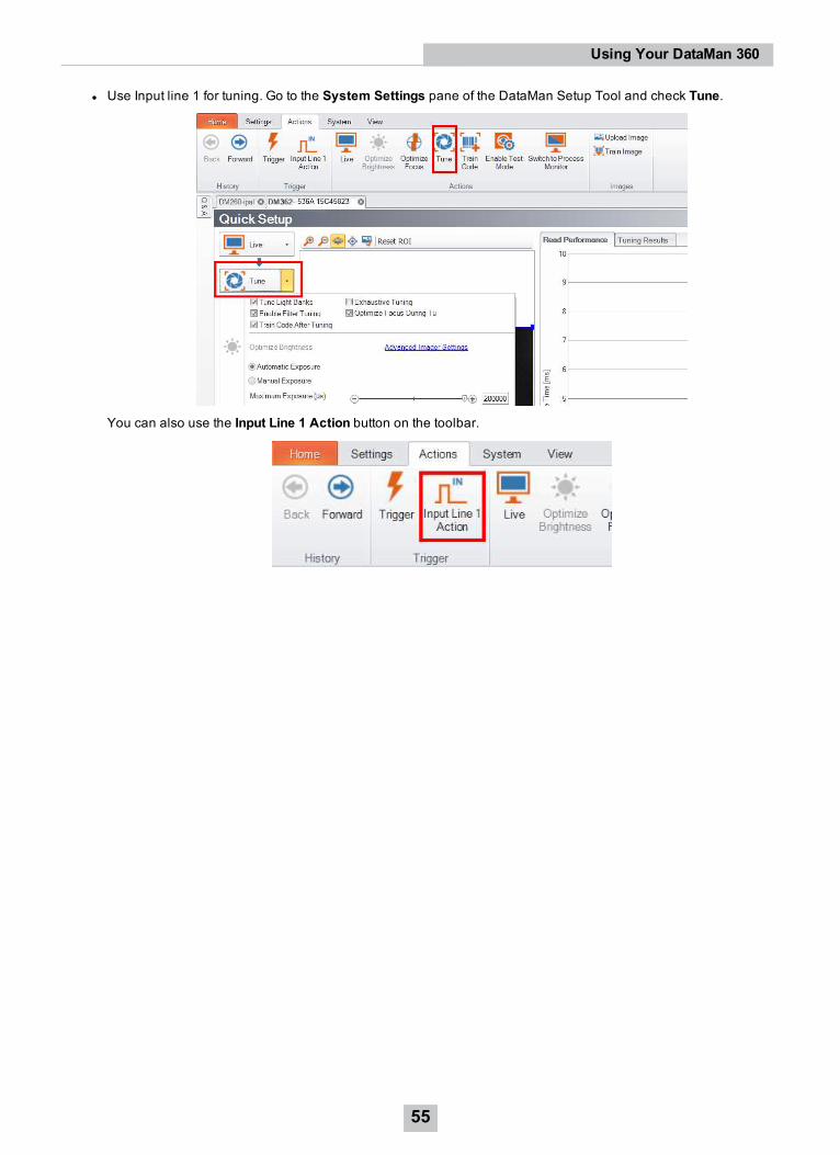
DataMan 360 Series TuningBy tuning, your reader automatically selects the best settings for the given reading situation, based on parameters ofillumination, camera and decoder properties, and focal distance. Tuning autodisciminates all enabled symbologies (both1-D and 2-D). If multiple symbols are found in the field of view, tuning locks on the first one found. Use this feature tocreate an optimum setting to read your codes.
You can use any of the following methods to tune your reader:
l Press the Tune button at least for 3 seconds on your reader. The first press starts the tuning, and the secondpress cancels the tuning, if it is still ongoing.
53
Using Your DataMan 360
l Turn on tuning in the DataMan Setup Tool.
l Start tuning by sending a DMCC, for more information, see the DataMan Control Commands Documentation,available through the Windows Start menu or the DataMan Setup Tool Helpmenu.
54
Using Your DataMan 360
l Use Input line 1 for tuning. Go to the System Settings pane of the DataMan Setup Tool and check Tune.
You can also use the Input Line 1 Action button on the toolbar.
55
Using Your DataMan 360
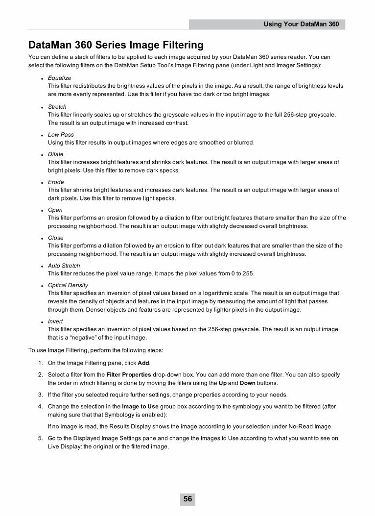
DataMan 360 Series Image FilteringYou can define a stack of filters to be applied to each image acquired by your DataMan 360 series reader. You canselect the following filters on the DataMan Setup Tool’s Image Filtering pane (under Light and Imager Settings):
l EqualizeThis filter redistributes the brightness values of the pixels in the image. As a result, the range of brightness levelsare more evenly represented. Use this filter if you have too dark or too bright images.
l StretchThis filter linearly scales up or stretches the greyscale values in the input image to the full 256-step greyscale.The result is an output image with increased contrast.
l Low PassUsing this filter results in output images where edges are smoothed or blurred.
l DilateThis filter increases bright features and shrinks dark features. The result is an output image with larger areas ofbright pixels. Use this filter to remove dark specks.
l ErodeThis filter shrinks bright features and increases dark features. The result is an output image with larger areas ofdark pixels. Use this filter to remove light specks.
l OpenThis filter performs an erosion followed by a dilation to filter out bright features that are smaller than the size of theprocessing neighborhood. The result is an output image with slightly decreased overall brightness.
l CloseThis filter performs a dilation followed by an erosion to filter out dark features that are smaller than the size of theprocessing neighborhood. The result is an output image with slightly increased overall brightness.
l Auto StretchThis filter reduces the pixel value range. It maps the pixel values from 0 to 255.
l Optical DensityThis filter specifies an inversion of pixel values based on a logarithmic scale. The result is an output image thatreveals the density of objects and features in the input image by measuring the amount of light that passesthrough them. Denser objects and features are represented by lighter pixels in the output image.
l InvertThis filter specifies an inversion of pixel values based on the 256-step greyscale. The result is an output imagethat is a “negative” of the input image.
To use Image Filtering, perform the following steps:
1. On the Image Filtering pane, click Add.
2. Select a filter from the Filter Properties drop-down box. You can add more than one filter. You can also specifythe order in which filtering is done by moving the filters using the Up and Down buttons.
3. If the filter you selected require further settings, change properties according to your needs.
4. Change the selection in the Image to Use group box according to the symbology you want to be filtered (aftermaking sure that that Symbology is enabled):
If no image is read, the Results Display shows the image according to your selection under No-Read Image.
5. Go to the Displayed Image Settings pane and change the Images to Use according to what you want to see onLive Display: the original or the filtered image.
56
Using Your DataMan 360
6. You can compare the original and filtered results on the Results Display if you choose the images from the ReadResult History.The example images were taken using the Equalize filter.
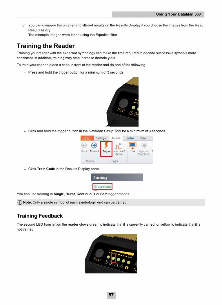
Training the ReaderTraining your reader with the expected symbology can make the time required to decode successive symbols moreconsistent. In addition, training may help increase decode yield.
To train your reader, place a code in front of the reader and do one of the following:
l Press and hold the trigger button for a minimum of 3 seconds.
l Click and hold the trigger button in the DataMan Setup Tool for a minimum of 3 seconds.
l Click Train Code in the Results Display pane.
You can use training in Single, Burst, Continuous or Self trigger modes.
Note: Only a single symbol of each symbology kind can be trained.
Training FeedbackThe second LED from left on the reader glows green to indicate that it is currently trained, or yellow to indicate that it isnot trained.
57
Using Your DataMan 360
Connect the reader to the DataMan Setup Tool to untrain it and allow it to recognize other enabled symbologies.
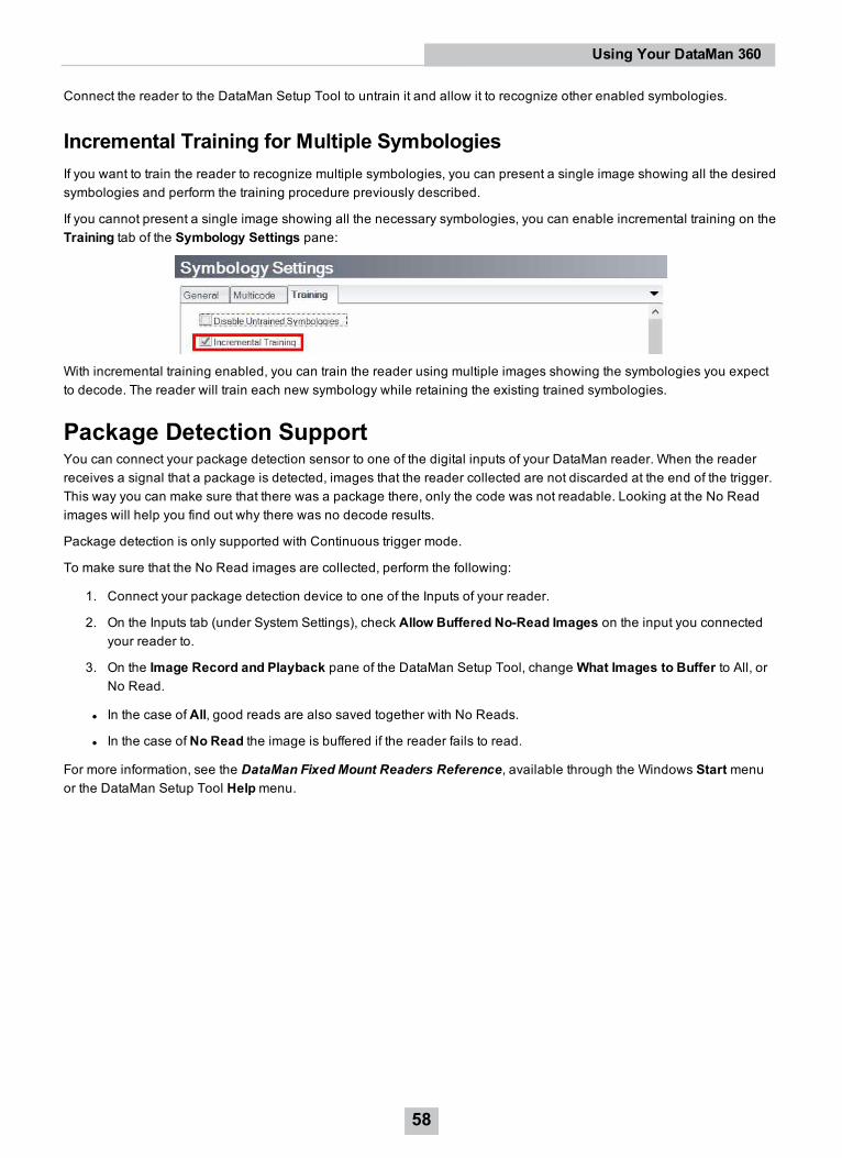
Incremental Training for Multiple SymbologiesIf you want to train the reader to recognize multiple symbologies, you can present a single image showing all the desiredsymbologies and perform the training procedure previously described.
If you cannot present a single image showing all the necessary symbologies, you can enable incremental training on theTraining tab of the Symbology Settings pane:
With incremental training enabled, you can train the reader using multiple images showing the symbologies you expectto decode. The reader will train each new symbology while retaining the existing trained symbologies.
Package Detection SupportYou can connect your package detection sensor to one of the digital inputs of your DataMan reader. When the readerreceives a signal that a package is detected, images that the reader collected are not discarded at the end of the trigger.This way you can make sure that there was a package there, only the code was not readable. Looking at the No Readimages will help you find out why there was no decode results.
Package detection is only supported with Continuous trigger mode.
To make sure that the No Read images are collected, perform the following:
1. Connect your package detection device to one of the Inputs of your reader.
2. On the Inputs tab (under System Settings), check Allow Buffered No-Read Images on the input you connectedyour reader to.
3. On the Image Record and Playback pane of the DataMan Setup Tool, changeWhat Images to Buffer to All, orNo Read.
l In the case of All, good reads are also saved together with No Reads.
l In the case of No Read the image is buffered if the reader fails to read.
For more information, see the DataMan Fixed Mount Readers Reference, available through the Windows Start menuor the DataMan Setup Tool Helpmenu.
58
Using Your DataMan 360
Connections, Optics, and LightingThis section contains descriptions about the external light control, I/O Cables, high-speed outputs, high-speed outputwiring, Ethernet M12 to RJ45 cable, and acquisition trigger.
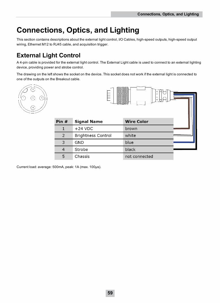
External Light ControlA 4-pin cable is provided for the external light control. The External Light cable is used to connect to an external lightingdevice, providing power and strobe control.
The drawing on the left shows the socket on the device. This socket does not work if the external light is connected toone of the outputs on the Breakout cable.
Current load: average: 500mA, peak: 1A (max. 100µs).
59
Connections, Optics, and Lighting
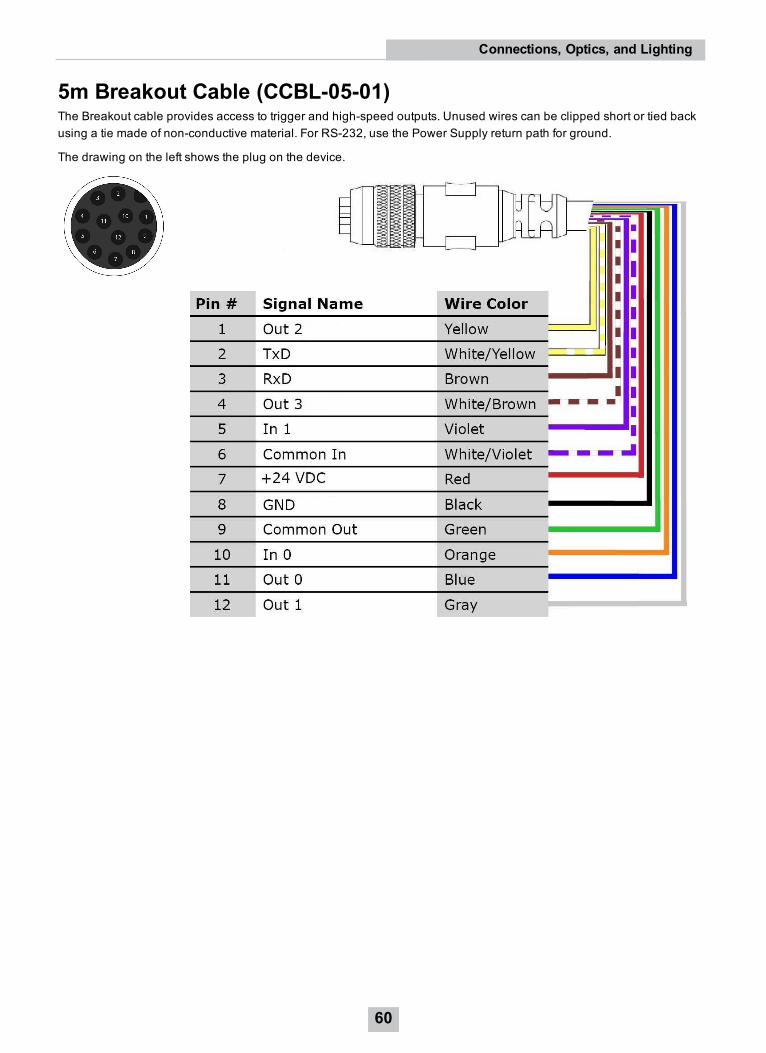
5m Breakout Cable (CCBL-05-01)The Breakout cable provides access to trigger and high-speed outputs. Unused wires can be clipped short or tied backusing a tie made of non-conductive material. For RS-232, use the Power Supply return path for ground.
The drawing on the left shows the plug on the device.
60
Connections, Optics, and Lighting
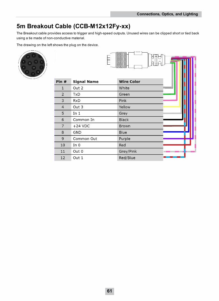
5m Breakout Cable (CCB-M12x12Fy-xx)The Breakout cable provides access to trigger and high-speed outputs. Unused wires can be clipped short or tied backusing a tie made of non-conductive material.
The drawing on the left shows the plug on the device.
61
Connections, Optics, and Lighting
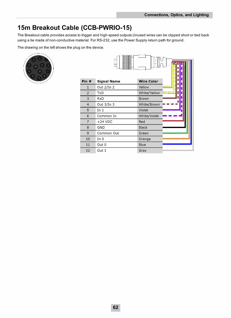
15m Breakout Cable (CCB-PWRIO-15)The Breakout cable provides access to trigger and high-speed outputs.Unused wires can be clipped short or tied backusing a tie made of non-conductive material. For RS-232, use the Power Supply return path for ground.
The drawing on the left shows the plug on the device.
62
Connections, Optics, and Lighting
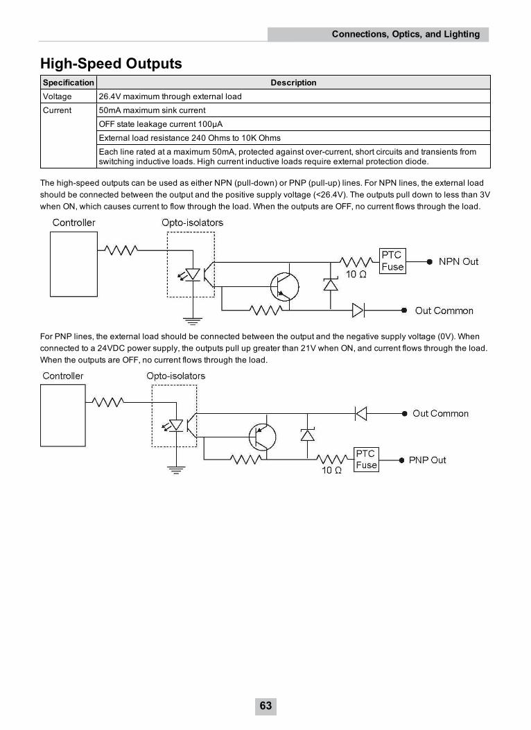
High-Speed OutputsSpecification DescriptionVoltage 26.4V maximum through external loadCurrent 50mA maximum sink current
OFF state leakage current 100µAExternal load resistance 240 Ohms to 10K OhmsEach line rated at a maximum 50mA, protected against over-current, short circuits and transients fromswitching inductive loads. High current inductive loads require external protection diode.
The high-speed outputs can be used as either NPN (pull-down) or PNP (pull-up) lines. For NPN lines, the external loadshould be connected between the output and the positive supply voltage (<26.4V). The outputs pull down to less than 3Vwhen ON, which causes current to flow through the load. When the outputs are OFF, no current flows through the load.
For PNP lines, the external load should be connected between the output and the negative supply voltage (0V). Whenconnected to a 24VDC power supply, the outputs pull up greater than 21V when ON, and current flows through the load.When the outputs are OFF, no current flows through the load.
63
Connections, Optics, and Lighting
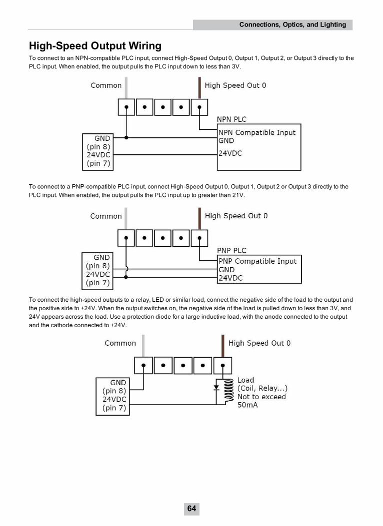
High-Speed Output WiringTo connect to an NPN-compatible PLC input, connect High-Speed Output 0, Output 1, Output 2, or Output 3 directly to thePLC input. When enabled, the output pulls the PLC input down to less than 3V.
To connect to a PNP-compatible PLC input, connect High-Speed Output 0, Output 1, Output 2 or Output 3 directly to thePLC input. When enabled, the output pulls the PLC input up to greater than 21V.
To connect the high-speed outputs to a relay, LED or similar load, connect the negative side of the load to the output andthe positive side to +24V. When the output switches on, the negative side of the load is pulled down to less than 3V, and24V appears across the load. Use a protection diode for a large inductive load, with the anode connected to the outputand the cathode connected to +24V.
64
Connections, Optics, and Lighting
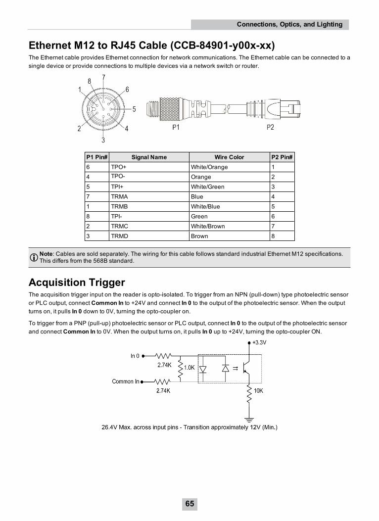
Ethernet M12 to RJ45 Cable (CCB-84901-y00x-xx)The Ethernet cable provides Ethernet connection for network communications. The Ethernet cable can be connected to asingle device or provide connections to multiple devices via a network switch or router.
P1 Pin# Signal Name Wire Color P2 Pin#6 TPO+ White/Orange 14 TPO- Orange 25 TPI+ White/Green 37 TRMA Blue 41 TRMB White/Blue 58 TPI- Green 62 TRMC White/Brown 73 TRMD Brown 8
Note: Cables are sold separately. The wiring for this cable follows standard industrial Ethernet M12 specifications.This differs from the 568B standard.
Acquisition TriggerThe acquisition trigger input on the reader is opto-isolated. To trigger from an NPN (pull-down) type photoelectric sensoror PLC output, connect Common In to +24V and connect In 0 to the output of the photoelectric sensor. When the outputturns on, it pulls In 0 down to 0V, turning the opto-coupler on.
To trigger from a PNP (pull-up) photoelectric sensor or PLC output, connect In 0 to the output of the photoelectric sensorand connect Common In to 0V. When the output turns on, it pulls In 0 up to +24V, turning the opto-coupler ON.
65
Connections, Optics, and Lighting
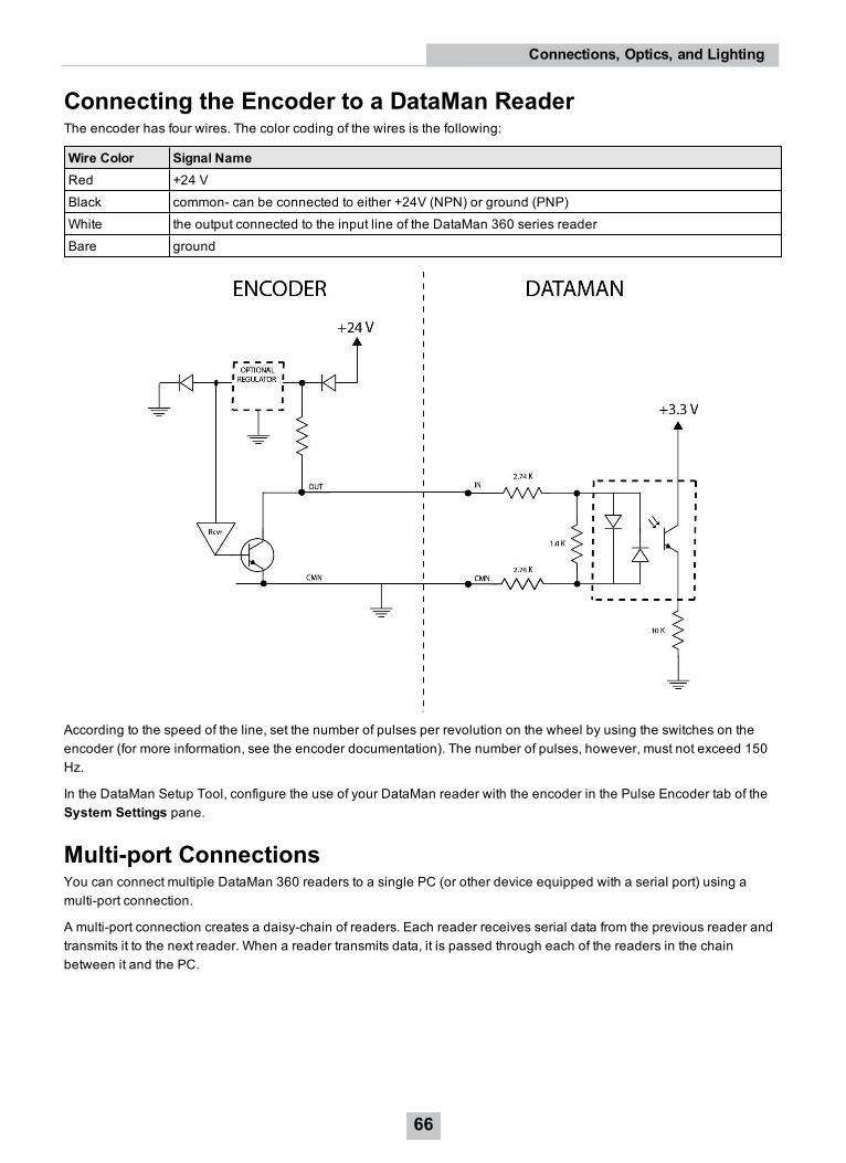
Connecting the Encoder to a DataMan ReaderThe encoder has four wires. The color coding of the wires is the following:
Wire Color Signal NameRed +24 VBlack common- can be connected to either +24V (NPN) or ground (PNP)White the output connected to the input line of the DataMan 360 series readerBare ground
According to the speed of the line, set the number of pulses per revolution on the wheel by using the switches on theencoder (for more information, see the encoder documentation). The number of pulses, however, must not exceed 150Hz.
In the DataMan Setup Tool, configure the use of your DataMan reader with the encoder in the Pulse Encoder tab of theSystem Settings pane.
Multi-port ConnectionsYou can connect multiple DataMan 360 readers to a single PC (or other device equipped with a serial port) using amulti-port connection.
A multi-port connection creates a daisy-chain of readers. Each reader receives serial data from the previous reader andtransmits it to the next reader. When a reader transmits data, it is passed through each of the readers in the chainbetween it and the PC.
66
Connections, Optics, and Lighting
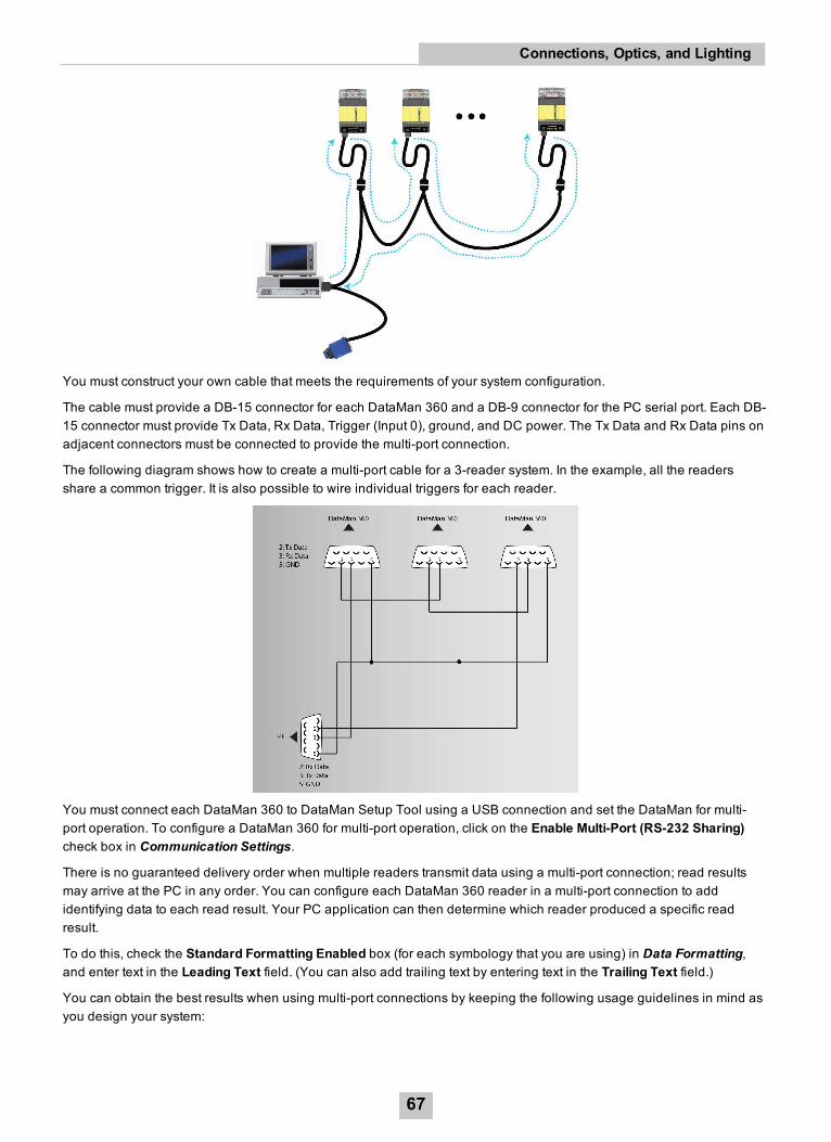
You must construct your own cable that meets the requirements of your system configuration.
The cable must provide a DB-15 connector for each DataMan 360 and a DB-9 connector for the PC serial port. Each DB-15 connector must provide Tx Data, Rx Data, Trigger (Input 0), ground, and DC power. The Tx Data and Rx Data pins onadjacent connectors must be connected to provide the multi-port connection.
The following diagram shows how to create a multi-port cable for a 3-reader system. In the example, all the readersshare a common trigger. It is also possible to wire individual triggers for each reader.
You must connect each DataMan 360 to DataMan Setup Tool using a USB connection and set the DataMan for multi-port operation. To configure a DataMan 360 for multi-port operation, click on the Enable Multi-Port (RS-232 Sharing)check box in Communication Settings.
There is no guaranteed delivery order when multiple readers transmit data using a multi-port connection; read resultsmay arrive at the PC in any order. You can configure each DataMan 360 reader in a multi-port connection to addidentifying data to each read result. Your PC application can then determine which reader produced a specific readresult.
To do this, check the Standard Formatting Enabled box (for each symbology that you are using) in Data Formatting,and enter text in the Leading Text field. (You can also add trailing text by entering text in the Trailing Text field.)
You can obtain the best results when using multi-port connections by keeping the following usage guidelines in mind asyou design your system:
67
Connections, Optics, and Lighting
l The maximum cable length between any two DataMan 360 readers or between the PC and any DataMan readershould be no greater than 15 meters.
l There is no fixed limit to the number of DataMan 360 readers that you can connect to a single PC. Each readerintroduces a delay of about 100 ms when it retransmits received serial data. If you have 5 readers, this meansthat there will be a 400 ms delay between the time the first reader in the chain transmits data and the PC receivesit.
l Each DataMan 360 reader must receive a hardware trigger signal on its Input 0 line. You can wire the input portsto a common trigger signal or you can provide individual triggers for each reader.
l Each DataMan 360 reader must be individually configured for multi-port operation, and you must perform thisconfiguration using a USB connection.
l If any reader in the multi-port chain loses power or becomes disconnected, then no data from any other readerwill be transmitted.
l If a DataMan 360 is transmitting its own read result, it will buffer any data received from another reader until it hasfinished its own data transmission. If a DataMan 360 is transmitting another reader’s data, it will buffer its owndata if it receives a trigger signal while it is processing the other reader’s data.
l If you use a single power supply for multiple readers, make sure that the power supply can provide enoughpower for all of the readers.
68
Connections, Optics, and Lighting
Cleaning/MaintenanceCleaning the Reader Housing
To clean the outside of the reader housing, use a small amount of mild detergent cleaner or isopropyl alcohol on acleaning cloth. Do not pour the cleaner directly onto the reader housing.
CAUTION: Do not attempt to clean any DataMan product with harsh or corrosive solvents, including lye, methylethyl ketone (MEK) or gasoline.
Cleaning the Reader Lens Cover
To remove dust from the lens cover, use a pressurized air duster. The air must be free of oil, moisture or othercontaminants that could remain on the lens cover. To clean the plastic window of the lens cover, use a small amount ofisopropyl alcohol on a cleaning cloth. Do not scratch the plastic window. Do not pour the alcohol directly on the plasticwindow.
69
Cleaning/Maintenance
Compliance Information, Warnings and NoticesPrecautions
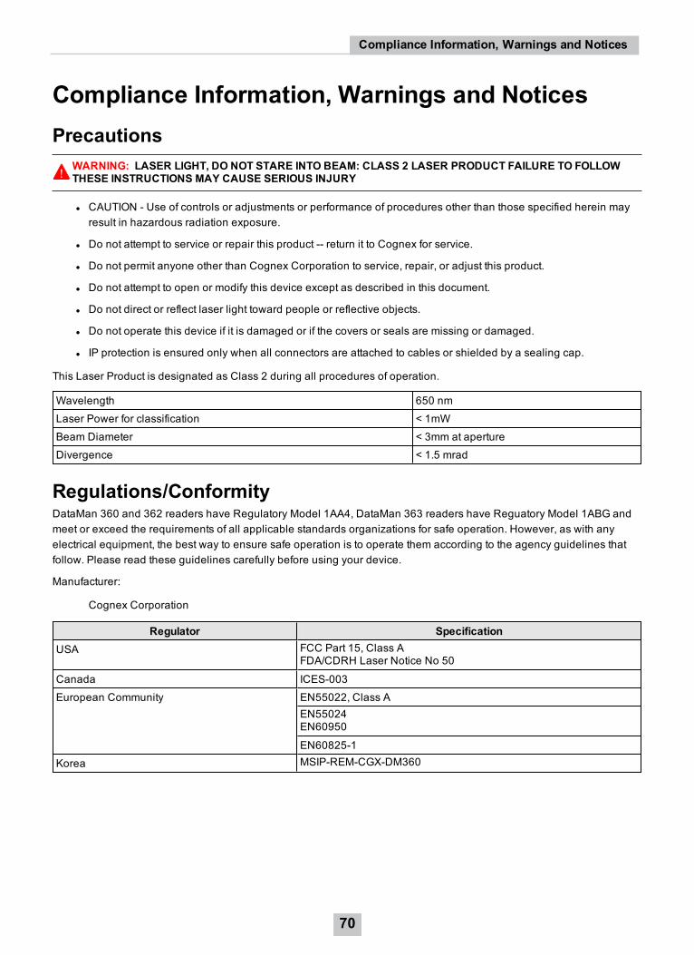
WARNING: LASER LIGHT, DO NOT STARE INTO BEAM: CLASS 2 LASER PRODUCT FAILURE TO FOLLOWTHESE INSTRUCTIONS MAY CAUSE SERIOUS INJURY
l CAUTION - Use of controls or adjustments or performance of procedures other than those specified herein mayresult in hazardous radiation exposure.
l Do not attempt to service or repair this product -- return it to Cognex for service.
l Do not permit anyone other than Cognex Corporation to service, repair, or adjust this product.
l Do not attempt to open or modify this device except as described in this document.
l Do not direct or reflect laser light toward people or reflective objects.
l Do not operate this device if it is damaged or if the covers or seals are missing or damaged.
l IP protection is ensured only when all connectors are attached to cables or shielded by a sealing cap.
This Laser Product is designated as Class 2 during all procedures of operation.
Wavelength 650 nmLaser Power for classification < 1mWBeam Diameter < 3mm at apertureDivergence < 1.5 mrad
Regulations/ConformityDataMan 360 and 362 readers have Regulatory Model 1AA4, DataMan 363 readers have Reguatory Model 1ABG andmeet or exceed the requirements of all applicable standards organizations for safe operation. However, as with anyelectrical equipment, the best way to ensure safe operation is to operate them according to the agency guidelines thatfollow. Please read these guidelines carefully before using your device.
Manufacturer:
Cognex Corporation
Regulator SpecificationUSA FCC Part 15, Class A
FDA/CDRH Laser Notice No 50
Canada ICES-003European Community EN55022, Class A
EN55024EN60950
EN60825-1Korea MSIP-REM-CGX-DM360
70
Compliance Information, Warnings and Notices
Safety and RegulatoryEuropeanCompliance WARNING: This is a class A product. In a domestic environment this product may cause radio
interference in which case the user may be required to take adequate measures.
The CE mark on the product indicates that the system has been tested to and conforms to the provisionsnoted within the 2014/30/EU Electromagnetic Compatibility Directive. For further information pleasecontact: Cognex Corporation, One Vision Drive, Natick, MA 01760, USA . Cognex Corporation shall notbe liable for use of our product with equipment (i.e., power supplies, personal computers, etc.) that is notCE.
FCC ClassAComplianceStatement
This equipment has been tested and found to comply with the limits for a Class A digital device, pursuantto Part 15 of the FCC rules. These limits are designed to provide reasonable protection against harmfulinterference when the equipment is operated in commercial environment. This equipment generates,uses, and can radiate radio frequency energy and, if not installed and used in accordance with theinstructions, may cause harmful interference to radio communications. Operation of this equipment in aresidential area is likely to cause harmful interference, in which case the user will be required to correctthe interference at personal expense.
CanadianCompliance
This Class A digital apparatus complies with Canadian ICES-003. Cet appareil numérique de la classe Aest conforme à la norme NMB-003 du Canada.
C-TickStatement
Conforms to AS/NZS CISPR 22/ EN 55022 for Class A Equipment.
UL and cULStatement
UL and cUL listed: UL60950-1 2nd ed. and CSA C22.2 No.60950-1 2nd ed.
Laser Safety StatementCompliance with FDA performance standards for laser products except for deviations pursuant to Laser NoticeNo. 50, dated June 24, 2007.
This device has been tested in accordance with IEC60825-1 2nd ed., and has been certified to be under the limits of aClass 2 Laser device.
Use of controls or adjustments or performance of procedures other than those specified herein may result in hazardousradiation exposure.
LED Safety StatementThis device has been tested in accordance with IEC62471, and red illumination has been certified to be under the limitsof Exempt Risk Group, blue and white illuminations have been certified to be under the limits of Risk Group 1 (Low-Risk).No further labeling is required.
For European Community UsersCognex complies with Directive 2012/19/EU OF THE EUROPEAN PARLIAMENT AND OF THE COUNCIL of 4 July 2012on waste electrical and electronic equipment (WEEE).
This product has required the extraction and use of natural resources for its production. It may contain hazardoussubstances that could impact health and the environment, if not properly disposed.
71
Compliance Information, Warnings and Notices
In order to avoid the dissemination of those substances in our environment and to diminish the pressure on the naturalresources, we encourage you to use the appropriate take-back systems for product disposal. Those systems will reuse orrecycle most of the materials of the product you are disposing in a sound way.
The crossed out wheeled bin symbol informs you that the product should not be disposed of along with municipalwaste and invites you to use the appropriate separate take-back systems for product disposal.
If you need more information on the collection, reuse, and recycling systems, please contact your local or regional wasteadministration.
You may also contact your supplier for more information on the environmental performance of this product.
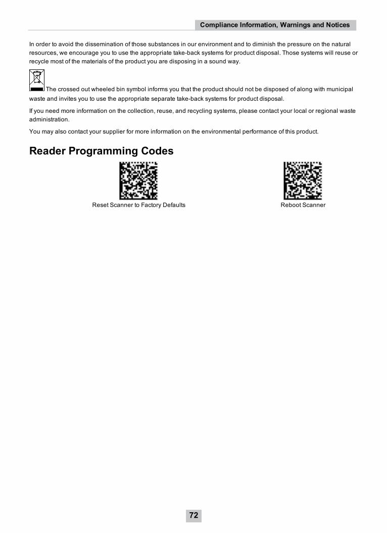
Reader Programming Codes
Reset Scanner to Factory Defaults Reboot Scanner
72
Compliance Information, Warnings and Notices

Copyright © 2017Cognex Corporation. All Rights Reserved.


![FEIS TableOfContents[1]](https://img.pdfslide.us/doc/110x75/577d366b1a28ab3a6b9308e2/feis-tableofcontents1.jpg)