Embed Size (px)
Citation preview
{Customer}
Cable Standards
Published by: {Customer} Information Technology – Planning & Engineering Dept
Revision H May 31, 2012 Jim Chorey
Biomedical Research Institute CABLE STANDARDS
Table of Contents 1
TABLE OF CONTENTS
SECTION 27 00 00 – COMMUNICATIONS SYSTEMS ......................................................................... 3
PART 1 - GENERAL ................................................................................................................................. 3 PART 2 – PRODUCTS .............................................................................................................................17 PART 3 – EXECUTION ...........................................................................................................................18
SECTION 27 05 26 – GROUNDING AND BONDING FOR COMMUNICATIONS SYSTEMS .......22
PART 1 - GENERAL ................................................................................................................................22 PART 2 – PRODUCTS ...........................................................................................................................23 PART 3 – EXECUTION .........................................................................................................................24
SECTION 27 05 28 – PATHWAYS FOR COMMUNICATIONS SYSTEMS ......................................30
PART 1 - GENERAL ..............................................................................................................................30 PART 2 – PRODUCTS ...........................................................................................................................32 PART 3 - EXECUTION ..........................................................................................................................32
SECTION 27 05 28.29 – HANGERS AND SUPPORTS FOR COMMUNICATIONS SYSTEMS......37
PART 1 – GENERAL ..............................................................................................................................37 PART 2 – PRODUCTS ...........................................................................................................................38 PART 3 – EXECUTION .........................................................................................................................38
SECTION 27 05 28.33 –CONDUIT AND BACK BOXES FOR COMMUNICATIONS SYSTEMS ..40
PART 1 - GENERAL ..............................................................................................................................40 PART 2 – PRODUCTS ...........................................................................................................................41 PART 3 – EXECUTION .........................................................................................................................41
SECTION 27 05 28.36 – CABLE TRAY ...................................................................................................45
PART 1 - GENERAL ..............................................................................................................................45 PART 2 – PRODUCTS ...........................................................................................................................48 PART 3 – EXECUTION .........................................................................................................................50
SECTION 27 05 28.43 –FIRESTOPPING FOR COMMUNIUCATIONS SYSTEMS .........................55
PART 1 – GENERAL ..............................................................................................................................55 PART 2 – PRODUCTS ...........................................................................................................................57 PART 3 – EXECUTION .........................................................................................................................57
SECTION 27 05 53 – IDENTIFICATION FOR COMMUNICATIONS SYSTEMS ...........................59
PART 1 - GENERAL ..............................................................................................................................59 PART 2 – PRODUCTS ...........................................................................................................................60 PART 3 – EXECUTION .........................................................................................................................60
SECTION 27 10 00 – STRUCTURED CABLING ...................................................................................71
PART 1 - GENERAL ..............................................................................................................................71 PART 2 – PRODUCTS ...........................................................................................................................76 PART 3 – EXECUTION .........................................................................................................................76
SECTION 27 11 00 – COMMUNICATIONS EQUIPMENT ROOM FITTINGS ................................89
PART 1 – GENERAL ..............................................................................................................................89 PART 2 – PRODUCTS ...........................................................................................................................98 PART 3 – EXECUTION .........................................................................................................................98
SECTION 27 11 13 – COMMUNICATIONS ENTRANCE PROTECTION ......................................100
PART 1 – GENERAL ............................................................................................................................100 PART 2 – PRODUCTS .........................................................................................................................101 PART 3 – EXECUTION .......................................................................................................................101
{Customer} CABLE STANDARDS
Table of contents 2
SECTION 27 11 16 – COMMUNICATIONS CABINETS, RACKS, FRAMES, AND ENCLOSURES
.....................................................................................................................................................................103
PART 1 – GENERAL ............................................................................................................................103 PART 2 – PRODUCTS .........................................................................................................................104 PART 3 – EXECUTION .......................................................................................................................104
SECTION 27 11 19 – COMMUNICATIONS TERMINATION BLOCKS AND PATCH PANELS 109
PART 1 – GENERAL ............................................................................................................................109 PART 2 – PRODUCTS .........................................................................................................................110 PART 3 – EXECUTION .......................................................................................................................110
SECTION 27 11 23 – COMMUNICATIONS CABLE MANAGEMENT AND LADDER TRAY ....113
PART 1 – GENERAL ............................................................................................................................113 PART 2 – PRODUCTS .........................................................................................................................114 PART 3 – EXECUTION .......................................................................................................................114
SECTION 27 13 00 – COMMUNICATIONS BACKBONE CABLING ..............................................119
PART 1 – GENERAL ............................................................................................................................119 PART 2 – PRODUCTS .........................................................................................................................120 PART 3 – EXECUTION .......................................................................................................................120
SECTION 27 13 13 – COMMUNICATIONS COPPER BACKBONE CABLING .............................122
PART 1 – GENERAL ............................................................................................................................122 PART 2 – PRODUCTS .........................................................................................................................123 PART 3 – EXECUTION .......................................................................................................................123
SECTION 27 13 23 – COMMUNICATIONS OPTICAL FIBER BACKBONE CABLING ..............125
PART 1 – GENERAL ............................................................................................................................125 PART 2 – PRODUCTS .........................................................................................................................126 PART 3 – EXECUTION .......................................................................................................................126
SECTION 27 13 23.13 – COMMUNICATIONS OPTICAL FIBER SPLICING AND
TERMINATIONS .....................................................................................................................................129
PART 1 – GENERAL ............................................................................................................................129 PART 2 – PRODUCTS .........................................................................................................................130 PART 3 – EXECUTION .......................................................................................................................130
SECTION 27 15 13 – COMMUNICATIONS COPPER HORIZONTAL CABLING ........................132
PART 1 – GENERAL .............................................................................................................................132 PART 2 – PRODUCTS .........................................................................................................................133 PART 3 – EXECUTION .......................................................................................................................133
SECTION 27 15 43 – COMMUNICATIONS FACEPLATES AND CONNECTORS .......................135
PART 1 – GENERAL .............................................................................................................................135 PART 2 – PRODUCTS .........................................................................................................................140 PART 3 – EXECUTION .......................................................................................................................141
SECTION 27 16 13 – COMMUNICATIONS CUSTOM CABLE ASSEMBLIES ..............................143
PART 1 – GENERAL .............................................................................................................................143 PART 2 – PRODUCTS .........................................................................................................................144 PART 3 – EXECUTION .......................................................................................................................144
APPENDIX A: ...........................................................................................................................................147
{Customer} / SCCA CABLE STANDARDS
Section 27 00 00 – Communications Systems 3
SECTION 27 00 00 – COMMUNICATIONS SYSTEMS PART 1 - GENERAL
1.01 GENERAL
A. PURCHASER BACKGROUND AND PROJECT DESCRIPTION
{Insert background information for your institute here.}
B. {Insert Description of Project Here}
1.02 INFRASTRUCTURE DESIGN CRITERIA
A. INTRODUCTION
a. General Planning Considerations
i. The A&E shall edit the information in the {Customer} Cable Standards
document by deleting those portions that do not apply to the project at
hand and by adding other information as required to provide the
Contractor with a complete specification package. Paragraphs known to
require editing are highlighted by double brackets.
ii. Generally, the design of communications system cable plant can begin
only after a thorough investigation of client requirements. The design
process must also resolve questions of available technology, media,
topology, and capacity planning. The A&E shall coordinate this survey of
occupant needs with {Customer}. {Customer} input early on in the
design process will make effective use of A&E time as well as save
money for the project over the course of construction.
iii. The A&E shall prepare Construction Documents after carefully reviewing
both the material in the following paragraphs and Sections {Customer}
Cable Standards document for additional detailed information. The A&E
must edit all Sections {Customer} Cable Standards document to meet
project requirements. The A&E is required to present to {Customer} all
drafted edits to specifications for each project. Redline markups or Word
document “track changes” are acceptable.
iv. The cable plant design is reflected on the Outlet Schedule prepared in
accordance with the guidelines presented in {Customer} Cable Standards
document.
v. The A&E is required to complete an Outlet Schedule at Design
Development showing all outlets by IDF, outlet labels, and quantity of
cable per outlet. The Outlet Schedule shall be developed by A&E using
the information provided in this design guide. When completed, A&E

{Customer} CABLE STANDARDS
Section 27 00 00 – Communications Systems 4
will provide this Outlet Schedule to {Customer}. In the event of multiple
riser room stacks, the Engineer is required to provide an IDF termination
division line on the design drawings to clearly delineate which IDF’s serve
which outlets.
vi. A&E is required to submit completed Outlet Schedule and completed floor
plan at Design Development.
1.03 THE BASIC MODEL
A. Major Components
a. The infrastructure design for {Customer} projects consists of the following major
components:
i. Outside Plant Infrastructure
ii. MDF/IDF Rooms and Riser System
iii. Horizontal Distribution System
iv. Station Distribution System
v. Pathways and Outlets
b. The design standards for the infrastructure system are described immediately
below in Part 1. Detailed installation specifications are contained in the
appropriate sections in this document.
c. The design standards for the cable plant system are described below in Part 2.
Detailed installation specifications are contained in the appropriate sections in this
document.
1.04 GENERAL PLANNING CONSIDERATIONS
A. The communications infrastructure and cable plant design can be reasonably
determined before the number of actual offices and communications outlets are
known. This can be accomplished by using the gross square footage (GSF) of the
building as a benchmark.
B. The GSF is the sum of all areas on all floors of a building including building service
spaces. Space defined as building service includes circulation, mechanical, structural,
etc.
C. The Formula for Planning and ESTIMATED BUDGETARY Purposes for Office
Buildings: Estimate the maximum number of outlets that must be supported if all
areas were remodeled to contain nothing but high-density office space. Use 100 GSF
as a standard office size for this calculation. The number of communications outlets
to be equal to the total building GSF divided by 100. During the actual design
process, the criteria for determining the number of actual outlets are different. This
formula provides the total outlets. For cable estimate, multiply the outlet quantity by
the standard outlet density of 4 cables.
{Customer} CABLE STANDARDS
Section 27 00 00 – Communications Systems 5
D. The Formula for Planning and ESTIMATED BUDGETARY Purposes for
Research/Lab/High-Technology Areas: Estimate the maximum number of outlets
that must be supported if all areas were remodeled to contain nothing but high-density
office space. Use 150 GSF as a standard office size for this calculation. The number
of communications outlets to be equal to the total building GSF divided by 150.
During the actual design process, the criteria for determining the number of actual
outlets are different. This formula provides the total outlets. For cable estimate,
multiply the outlet quantity by the standard outlet density of 4 cables.
E. These calculations are applicable at the initial programming phase and for budget
purposes only.
1.05 RELATED SECTIONS
A. 27 05 26 GROUNDING AND BONDING FOR COMMUNICATIONS SYSTEMS
B. 27 05 28 PATHWAYS FOR COMMUNICATIONS SYSTEMS
C. 27 05 28.29 HANGERS AND SUPPORTS FOR COMMUNICATIONS SYSTEMS
D. 27 05 28.33 CONDUITS AND BACKBOXES FOR COMMUNICATIONS
SYSTEMS
E. 20 05 28.36 CABLE TRAYS FOR COMMUNICATIONS SYSTEMS
F. 27 05 28.43 FIRESTOPPING FOR COMMUNICATIONS SYSTEMS
G. 27 05 53 IDENTIFICATIONS FOR COMMUNICATIONS SYSTEMS
H. 27 10 00 STRUCTURED CABLING FOR COMMUNICATIONS SYSTEMS
I. 27 11 00 EQUIPMENT ROOM FITTINGS FOR COMMUNICATIONS SYSTEMS
J. 27 11 13 ENTRANCE PROTECTION FOR COMMUNICATIONS SYSTEMS
K. 27 11 16 CABINETS, RACKS, FRAMES, AND ENCLOSURES FOR
COMMUNICATIONS SYSTEMS
L. 27.11 19 TERMINATIONS BLOCKS AND PATCH PANELS FOR
COMMUNICATIONS SYSTEMS
M. 27 11 23 CABLE MANAGEMENT AND LADDER RACK FOR
COMMUNICATIONS SYSTEMS
N. 27 13 00 BACKBONE CABLING FOR COMMUNCIATIONS SYSTEMS
O. 27 13 13 COPPER BACKBONE CABLING FOR COMMUNICATIONS
SYSTEMS
P. 27 13 23 OPTICAL FIBER BACKBONE CABLING FOR COMMUNICATIONS
SYSTEMS
27 13 23.13 OPTICAL FIBER SPLICING AND TERMINATIONS FOR
COMMUNICATIONS SYSTEMS
Q. 27 15 00 HORIZONTAL CABLING FOR COMMUNICATIONS SYSTEMS
R. 27 15 13 COPPER HORIZONTAL CABLING FOR COMMUNICATIOSN
SYSTEMS
S. 27 15 43 FACEPLATES AND CONNECTORS FOR COMMUNICATIONS
SYSTEMS
T. 27 16 00 CONNECTING CORDS, DEVICES, AND ADAPTERS FOR
COMMUNICATIONS SYSTEMS
U. 27 16 13 CUSTOM CABLE ASSEMBLIES FOR COMMUNICATIOSN
SYSTEMS
{Customer} CABLE STANDARDS
Section 27 00 00 – Communications Systems 6
1.06 REFERENCES
A. GENERAL
a. The following standards, specifications, codes and regulations shall be
incorporated by reference into this specification.
i. National Electric Code (NEC)
ii. National Electric Safety Code (NESC)
iii. Washington Industrial Safety and Health Act (WISHA)
iv. Occupational Safety and Health Act (OSHA)
v. Revised Code of Washington (RCW)
vi. Washington Administrative Code (WAC)
vii. International Building Code
viii. City of Seattle Uniform Building Code
ix. Bellcore standards.
x. ISO/IEC Standards.
xi. {Customer} Cable Standards
xii. {Customer} Internal Construction Standard for Fire Stopping
B. COMMUNICATIONS:
a. Unless specifically noted otherwise in the Construction Documents, the latest
Edition and current Addenda’s of the following publications shall be consulted as
Communications reference documents.
i. ANSI/TIA/EIA-526-7, Measurement of Optical Power Loss of Installed
Single-Mode Fiber Cable Plant.
ii. ANSI/TIA/EIA-526-14A, Measurement of Optical Power Loss of
Installed Multimode Fiber Cable Plant.
iii. ANSI/TIA/EIA-528-C.0, Telecommunications Cabling for Customer
Premises
iv. ANSI/TIA/EIA-568-C.1, Commercial Building Telecommunications
Cabling Standard.
v. ANSI/TIA/EIA-568-C.2, Balanced Twisted-Pair Cabling and Components
Standard.
vi. ANSI/TIA/EIA-568-C.3, Optical Fiber Cabling Components Standard.
vii. TIA -569-B, Commercial Building Standard for Telecommunications
Pathways and Spaces.
viii. ANSI/TIA/EIA-606-A, Administration Standard for Commercial
Telecommunications Infrastructure.
ix. J-STD-607-B, Telecommunications Grounding (Earthing) and Bonding
Requirements for Customer Premises.
x. ANSI/TIA/EIA-758-A: Customer Owned Outside Plant
Telecommunications Infrastructure Standard.
{Customer} CABLE STANDARDS
Section 27 00 00 – Communications Systems 7
xi. ANSI/TIA/EIA-862: Building Automation Systems Cabling Standard for
Commercial Buildings.
xii. ANSI/TIA-942A Telecommunications infrastructure Standard for Data
Centers.
xiii. ISO/IEC 11801: Generic Cabling for Customer Premises.
xiv. BICSI: BICSI Telecommunications Cabling Installation Manual (TCIM).
xv. BICSI: BICSI Telecommunications Distribution Methods Manual.
xvi. BISCI: BICSI Customer-Owned Outside Plant Design Manual.
xvii. Telcordia Technologies, Inc. (Bellcore) GR-771-CORE Generic
Requirements for Fiber Optic Splice Closures, November 2001.
C. DEFINITIONS:
a. Backbone cabling: Cable and connecting hardware that comprise the main and
intermediate cross-connects, as well as cable runs that extend between
telecommunications closets, equipment rooms, and entrance facilities.
b. Basic Link: The horizontal cable and connectors that complete a transmission
path between a work area outlet and a connecting block/patch panel in the
telecommunication room. Does not include patch cords.
c. Bonding: The permanent joining of metallic parts to form an electrically
conductive path that will assure electrical continuity and the capacity to conduct
safely any current likely to be imposed on it.
d. Building Entrance Facility (BEF): An entrance to a building for both public and
private network service cables including the entrance point at the building wall
and continuing to the entrance room or space.
e. Channel: The horizontal cable, patch cords, and connectors that complete a
transmission path between a work area outlet and a connecting block/patch panel
to application specific equipment. Does include patch cords.
f. Cross-Connection: A connection scheme between cabling runs, subsystems, and
equipment using patch cords or jumpers that attach to connecting hardware on
each end.
g. Demarcation Point: A point where operational control or ownership changes.
h. Electromagnetic Interference (EMI): The interference in signal transmission or
reception caused by electromagnetic radiation generated by other equipment or
cabling.
i. Electronic Industries Alliance (EIA): An organization that sets standards for
interfaces to ensure computability between data communications equipment and
data terminal equipment.
j. Equipment Room: A centralized space for telecommunications equipment that
serves the occupants of the building or multiple buildings in a campus
environment. An equipment room is considered distinct from a
telecommunications closet because it is considered to be a building or campus
serving (as opposed to floor serving) facility and because of the nature or
complexity of the equipment that it contains. See MDF Room
k. FCIC: Furnished by the Contractor Installed by the Contractor.
l. FCIO: Furnished by the Contractor Installed by the Owner.

{Customer} CABLE STANDARDS
Section 27 00 00 – Communications Systems 8
m. Firestop: A material, device, or assembly of parts installed in a cable pathway at a
fire-rated wall of floor penetration to prevent passage of flame, smoke, or gases
through the rated barrier.
n. FOIC: Furnished by the Owner Installed by the Contractor
o. FOIO: Furnished by the Owner Installed by the Owner.
p. Horizontal Cabling: The cabling between and including the telecommunications
outlet and the horizontal cross-connect.
q. Interconnection: A connection scheme that provides direct access to the cabling
infrastructure and the ability to make cabling system changes using equipment
cords.
r. Intermediate Distribution Frame (IDF): A structure with terminations for making
cross-connections between first level backbone cabling and horizontal cabling,
located in a telecommunications closet.
s. IDF Room: An enclosed space for housing telecommunications equipment, cable
terminations, and cross connect cabling used to serve work areas located on the
same floor. The IDF Room is the typical location of the horizontal cross-connect
and is considered distinct from an equipment room because it is considered to be
floor serving. See Telecommunications closet.
t. Main Distribution Frame (MDF): The main structure with terminations for
connecting the permanent cabling of a facility in such a manner that inter-
connection or cross-connections may be readily made. The MDF may be located
in the Equipment Room.
u. MDF Room: A centralized space for telecommunications equipment that serves
the occupants of the building or multiple buildings in a campus environment. An
MDF room is considered distinct from a telecommunications closet because it is
considered to be a building or campus serving (as opposed to floor serving)
facility and because of the nature or complexity of the equipment that it contains.
See Equipment Room
v. Multimode Optical Fiber: An optical fiber that will allow many modes to
propagate. The fiber will be laser optimized 50/125 um. Type OM-4.
w. Patch Panel: Connecting hardware that typically provides means to connect
horizontal or backbone cables to an arrangement of fixed connectors that may be
accessed using patch cords or equipment cords to form cross-connections or
interconnections.
x. Pathway: A facility (i.e. conduit or cable tray) for the placement and protection of
telecommunications cable. Same as raceway or ducting.
y. Permanent Link: The horizontal cable and connectors that complete a
transmission path between a work area outlet and a connecting block/patch panel
in the telecommunication room. Does not include patch cords.
z. Plenum: A compartment or chamber to which one or more air ducts are connected
and that forms part of the air distribution system within a building.
aa. Provide: This means to furnish and install complete and ready for use.
bb. Standard Information Outlet (SIO): standard telecommunications outlet which
consists of four Category 6 cables terminated to 8 pin modular jacks in a double
gang 8-port faceplate.
{Customer} CABLE STANDARDS
Section 27 00 00 – Communications Systems 9
cc. Telecommunications Room: An enclosed space for housing telecommunications
equipment, cable terminations, and cross connect cabling used to serve work areas
located on the same floor. The telecommunications room is the typical location of
the horizontal cross-connect and is considered distinct from an equipment room
because it is considered to be floor serving. See IDF room.
dd. Telecommunications Outlet: A fixed connecting device where the horizontal
cable terminates. The telecommunications outlet provides the interface to the
work area cabling.
ee. Telecommunications Industry Association (TIA): An organization that sets
standards for cabling, pathways, spaces, grounding, bonding, administration, field
testing, and other aspects of the telecommunications industry.
ff. Unshielded Twisted Pair (UTP): A cable with multiple pairs of twisted insulated
copper conductors bound in a single sheath.
gg. Work Area: The area where horizontal cabling is connected to the work area
equipment by means of a telecommunications outlet. A station/desk that is served
by a telecommunications outlet.
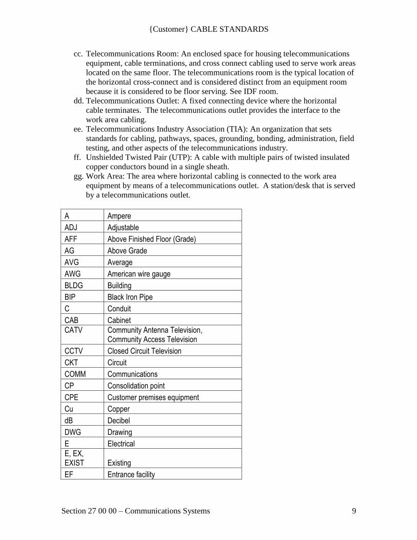
A Ampere
ADJ Adjustable
AFF Above Finished Floor (Grade)
AG Above Grade
AVG Average
AWG American wire gauge
BLDG Building
BIP Black Iron Pipe
C Conduit
CAB Cabinet
CATV
Community Antenna Television, Community Access Television
CCTV Closed Circuit Television
CKT Circuit
COMM Communications
CP Consolidation point
CPE Customer premises equipment
Cu Copper
dB Decibel
DWG Drawing
E Electrical
E, EX, EXIST Existing
EF Entrance facility

{Customer} CABLE STANDARDS
Section 27 00 00 – Communications Systems 10
ELEC Electrical
ELEV Elevator
EM Emergency
EMT Electrical Metallic Tubing
EQUIP Equipment
ER Equipment room
F Fahrenheit
FIG Figure
ft. Feet
FEXT Far-end crosstalk
FLR Floor
FUT Future
G Gas
GIP Galvanized Iron Pipe
GND Ground
GRS Galvanized Rigid Steel
HC Horizontal cross-connect
HH Handhole
HVAC Heating, ventilation and air conditioning
IG Isolated Ground
LAN Local area network
lbf Pounds force
lx Lux
LEC Local exchange carrier
m Meter
MAX Maximum
MH Manhole
MIN Minimum
mm Millimeter
MTG Mounting
NEC National Electrical Code (NFPA-70)
NEMA National Electrical Manufacturers Association
NFPA National Fire Protection Association
NIC Not In Contract
NTS Not to Scale
PA Paging
{Customer} CABLE STANDARDS
Section 27 00 00 – Communications Systems 11
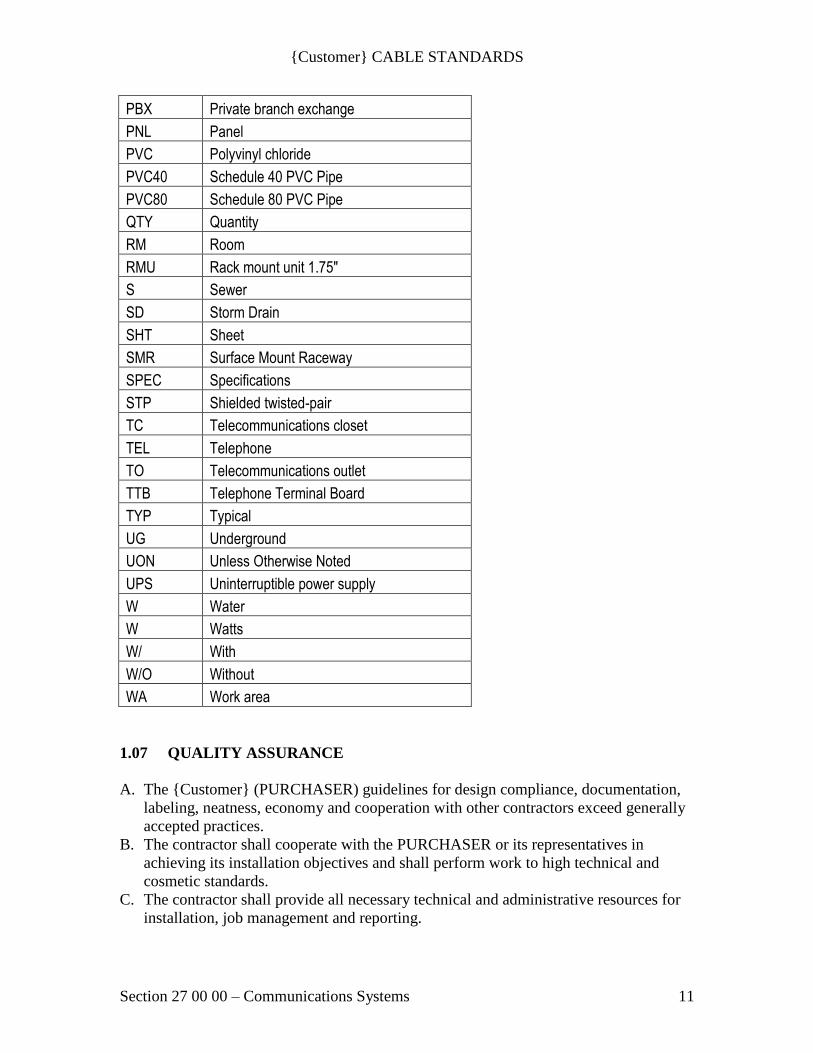
PBX Private branch exchange
PNL Panel
PVC Polyvinyl chloride
PVC40 Schedule 40 PVC Pipe
PVC80 Schedule 80 PVC Pipe
QTY Quantity
RM Room
RMU Rack mount unit 1.75"
S Sewer
SD Storm Drain
SHT Sheet
SMR Surface Mount Raceway
SPEC Specifications
STP Shielded twisted-pair
TC Telecommunications closet
TEL Telephone
TO Telecommunications outlet
TTB Telephone Terminal Board
TYP Typical
UG Underground
UON Unless Otherwise Noted
UPS Uninterruptible power supply
W Water
W Watts
W/ With
W/O Without
WA Work area
1.07 QUALITY ASSURANCE
A. The {Customer} (PURCHASER) guidelines for design compliance, documentation,
labeling, neatness, economy and cooperation with other contractors exceed generally
accepted practices.
B. The contractor shall cooperate with the PURCHASER or its representatives in
achieving its installation objectives and shall perform work to high technical and
cosmetic standards.
C. The contractor shall provide all necessary technical and administrative resources for
installation, job management and reporting.
{Customer} CABLE STANDARDS
Section 27 00 00 – Communications Systems 12
D. Upon selection of the cabling contractor, there shall be a meeting with PURCHASER
IT to determine the best design for horizontal and riser cabling pathways and
telecommunications room design.
E. All telecommunications services, equipment, cables, electronics power supplies, or
systems in operation at the start of the project shall remain in service and may not be
disconnected, removed or in any way impaired by the activities of the contractor
unless those changes are part of the project, coordinated and scheduled with the
clients project management team and the project telecommunications consultant.
a. Where active systems must remain in operation during a project, systems will be
clearly identified, tagged and documented.
b. Contractor shall include in their bids any costs necessary to protect or maintain
systems, which must remain active unless these items are expressly addressed in
bid response documents.
c. Contractor shall not remove any jumpers or patch cords. Removal of all jumpers
and patch cables shall be done by or at the direction of the client’s management
team or Information Services department representative.
F. Contractor shall be responsible for all coordination, costs and materials associated
with restoration of services for any damaged systems.
G. Contractor shall test all systems prior to demolition, to insure that no active systems
remain.
H. Unless specifically excluded in writing elsewhere, contractor shall be responsible to
obtain all necessary telecommunications installation permits, and shall be responsible
for all inspection costs, coordination and inspector approval.
I. Unless specifically excluded in writing elsewhere, contractor shall be responsible to
provide and maintain all necessary safety devices components and safety supervision
to protect the safety of pedestrians, building occupants, bystanders and contractors
employees.
J. Nothing in this document shall be construed or understood to authorize or direct
contractor to deviate from any telecommunications industry standard, federal, state,
or local safety law, standard, code or requirement.
K. A Project Manager shall be assigned to the project, who maintains a current RCDD®
registration and is responsible for quality control during installation, equipment set-
up, as-built documentation and testing.
a. The project manager shall provide their RCDD certification and resume to owner.
L. Owner and/or Project Manager shall at any time request a shop visit of the
manufacturing facilities of the equipment being installed for a quality audit of
product.
1.08 CONTRACTOR QUALIFICATIONS
A. Contractor shall have an established place of business within the local Puget Sound
area and have been in the business of installing communications cabling and
components for the past five years. All business associated with this project shall be
conducted from this local office.
B. Contractor shall use full time internal staffing resources for this project. A
subcontractor and/or temporary hired labor forces cannot fulfill this requirement.
{Customer} CABLE STANDARDS
Section 27 00 00 – Communications Systems 13
C. Contractor shall be able to demonstrate the immediate availability of currently
employed, qualified personnel committed to this project. Contractor shall provide
this within their bid response.
D. Contractor shall be a certified installer of all product solutions. This certification has
to be a “standing” certification not a project “only” certification.
E. Contractor shall have full time technicians on staff assigned to this project who are
competent in ADC Krone installations and:
a. Trained and certified by the manufacturer
b. Or trained in cable installation techniques by BICSI. Contractor shall establish
with manufacturer of cabling equipment that the training certification for
installers will be acceptable to the manufacturer for the full warranty of the
manufacturer equipment and installation. Contractor shall provide written
documentation to PURCHASER IT from the product manufacturer that the
installation will be warranted the same as installations by manufacturer
certified installers.
c. The contractor shall show proof that Category 6 UTP cable plant installation
will be warranted in full by the manufacturer ADC/Tyco.
F. Contractor shall provide installation services that meets or exceeds the requirements
for the cabling type/class/category provided.
G. Category 6 cabling standards are common in the {Customer} environment. Refer to
the Project Specifications Manual for the requirements of the project.
H. Contractor shall have the latest version of Auto CAD or AutoCAD LT and shall have
a minimum of (1) personnel assigned to this project who is trained in Auto CAD
(note; this personnel does not have to be assigned full time to this project).
Contractor shall indicate this within their bid response.
I. A Project Manager shall be assigned to the project, who maintains a current RCDD®
registration.
1.09 SUBMITTAL INFORMATION
A. Submit in accordance with the below requirements and standard project requirements.
B. Submit with bid response:
a. Resumes and certification of technicians for this project.
b. A proposed organization and work load chart for the project team that will be
committed to this project for its entirety. This should include the employee
names and assigned roles and involvement if any, with other projects during
this projects duration.
c. A proposed project schedule in accordance with the General Contractors
master project schedule.
C. Submit prior to start of installation:
a. A list of test equipment to be used on this project with identification numbers
and calibration certification. All certifications must be within the last (6)
months.
D. Contractor shall schedule a pre-installation conference with PURCHASER at a
minimum of (15) calendar days prior to beginning work.
E. Product Data Submittals:
{Customer} CABLE STANDARDS
Section 27 00 00 – Communications Systems 14
a. Provide vendor cut sheets and other appropriate submittal information for
PURCHASER IT review 10 days or more prior to jobsite delivery for
products not on {Customer} approved materials list. Provide all product data
submittals at the same time.
b. Contractor shall provide a letter stating intent to provide materials as specified
and identifying products that will not be provided as specified.
c. Products allowing “or equal” which are not being provided shall have
manufacturer cut sheets or other descriptive material submitted along with
reasons for the substitution. Project cost impact shall be included.
d. {Customer} must have 5 working days to review and approve submittals
before product and equipment is ordered.
e. Products and equipment ordered prior to {Customer} approval and rejected by
{Customer} shall be the total responsibility of the contractor for removal and
disposal. {Customer} shall incur no cost for removal and disposal of rejected
submittal materials and equipment.
F. Provide Operation and Maintenance (O&M) guides and manufacturer cut sheets for
each device in the system. These guides shall detail the building preparation
requirements, the installation process, and equipment service requirements.
G. Closeout Submittals:
a. Provide submittal information for review as follows:
i. O&M Manual for Communications – Contractor shall provide O&M
information for the product data submittals identifying changes to the
installation made during the construction process to the Engineer/Designer
for inclusion in the telecommunications O&M Manual for
Telecommunications Systems. The Engineer/Designer shall submit as a
binder appropriately labeled with project name and description.
ii. Records – The jobsite shall have a set of Record Drawings, Project
Specifications and Addenda. Record Drawings shall consist of redline
markups of drawings, specifications, spreadsheets and addenda.
b. Contractor shall document system changes from the original contract
documents.
c. Record drawings shall be available to the Owner and representatives and the
Engineer/Designer at any time.
d. Record drawings shall be kept current during construction (current is defined
as within one week behind actual construction).
H. Contractor shall provide a letter from the manufacturer of cabling products eligible
for manufacturer warranty that the contractor installation will qualify for full
manufacturer warranty if the contractor is not manufacturer certified for the
installation.
I. The contractor shall provide ADC/Tyco manufacturer certification that the Category
6 UTP cable plant installation will be warranted in full as installed. The contractor
shall show proof that ADC/Tyco will agree to warranty the Category 6 UTP cable
installation if the UTP cabling used is not ADC/Tyco cabling.
1.10 RECORD DOCUMENTS

{Customer} CABLE STANDARDS
Section 27 00 00 – Communications Systems 15
A. Contractor shall maintain a hard copy working set of documents at the project site
throughout the course of the project. This working set shall be continually updated
throughout the duration of the project for development of record drawings.
B. Contractor shall be responsible to provide a final set of project record drawings.
These drawings shall include the following;
C. Documentation of all work as constructed.
D. Documentation of all owner requested changes.
E. Documentation of field required changes due to conflicts with actual conditions.
F. Documentation of all device actual locations.
G. Documentation of project design variances of all horizontal and vertical pathways
from project design.
H. Documentation of variance of one-line infrastructure drawings.
I. Documentation of all floor plans indicating room and outlet identification numbers.
J. Within 10 working days of project completion, contractor shall provide (2) hard
copies of drafted project drawings and specifications reflecting all changes, revisions
and modifications to the original project plan as indicated above. This shall include
all information transferred from the contractors working set. Deliver in both
electronic and hard copy form.
K. Contractor shall provide (2) hard copies to PURCHASER of all change orders
(additional service requests) with a summary identifying the changes if they are not
clearly identified on the drawings.
L. Contractor shall provide (1) hard copy and an electronic copy of the summary report
for all infrastructure test results.
a. Cable test results shall be provided in original test set format and downloaded
and saved on permanent unalterable electronic media such as Compact Disk
or DVD media.
b. Software to read the test results shall be provided and shall be MicroSoft XP
compatible. The software shall provide an upgrade path from Windows XP to
Windows 7 or be backwards compatible to Windows XP.
M. Submit in electronic format (with all related files, such as XREF’s, and in AutoCAD
2008 or later drawing format and readable with AutoCAD LT 2008 and later) and
hard copy format, all updated drawings indicating the installed locations of
distribution cable runs.
N. Submit the below items prior to cut over, for use by other contractors according to a
schedule provided by the PURCHASER or its representatives:
a. Submit drawings indicating the installed locations of distribution cable runs.
b. Affix to a wall in each cable room a full size floor plan drawing (laminated)
showing numbered outlet locations served by the Telecomm room.
c. Submit a “room-to-jack” database in excel format showing outlet
identification numbers and associated room numbers.
d. Provide floor plan as-built CAD drawings with all XREFs in the 2008 or later
version of AutoCAD (AutoCAD LT readable) format to PURCHASER IT.
CAD files shall show all telecomm numbered faceplates. The intended use of
these files are to provide a modifiable drawing set that can be updated with
future adds, moves and changes.
O. Warranty:
{Customer} CABLE STANDARDS
Section 27 00 00 – Communications Systems 16
a. Provide two copies of a manufacturer and installation warranty binder
containing all warranty information for all components and contractors labor.
i. Provide two copies of signed and dated warranty documentation from the
manufacturer for all extended component warranties.
b. Provide two copies of a letter, on contractor firm’s letterhead, signed and
dated by a corporate officer or the regional manager, and additionally signed
by the project manager. The letter shall state that the materials utilized are as
specified in the contract, that installation complies with all applicable
manufacturers’ specifications and telecommunications industry standards, and
that the contractor performed all required cable and link tests.
c. Provide a contractor warranty on all labor such that any installation or
documentation found within one (2) years to be out of compliance with these
specifications will be promptly repaired or replaced at no charge.
P. All project record documents shall be provided to PURCHASER and the General
Contractor. All hard copies shall be provided in a single, complete correlated
package. All electronic copies shall be provided on unalterable CD or DVD media in
the most current release of the associated software program.
1.11 CONTRACTOR WARRANTY
A. Contractor shall provide a two year warranty against defects in materials and
workmanship in addition to the manufacturer installation warranty.
a. Provide labor and materials for this warranty at no cost to the owner.
b. Warranty period shall commence upon Owner acceptance of the project.
1.12 MANAGEMENT OF MATERIALS
A. It is the responsibility of the Bidder to calculate all actual copper and fiber cable
footage required.
B. Contractor shall purchase cable and materials as shown on attached bid response
form.
C. The successful Bidder shall be responsible for the shipping, handling, and storage of
all said material and equipment.
D. Contractor shall be present to receive and sign for materials upon arrival of each
shipment at the job site.
E. Contractor shall furnish and maintain lockable storage containers, in locations
designated by the general contractor, for the on-site secure storage of materials.
F. Contractor shall provide any materials not included in the bid response, which are
found to be necessary after contract execution, with the exception of materials made
necessary by a change in scope requested by the PURCHASER. Additional materials
must be as specified in this request, without substitution.
G. Contractor shall promptly report any request for additional materials or work in
writing and shall maintain written records of all additions (change order request)
separate from the original project. All changes to contractor’s project scope, system
routing, schedule or authorized budget must be approved in advance by the
PURCHASER. Contractor will not be paid for any work performed, or materials
{Customer} CABLE STANDARDS
Section 27 00 00 – Communications Systems 17
purchased without advance authorization and approval for the specific items of work
or materials by the PURCHASER.
1.13 COMMISSIONING
A. Contractor shall meet all requirements set forth by the project requirements.
B. During the Commissioning process and throughout the Warranty period the
contractor shall provide appropriate levels of on-site repair service and coordinate
with the PURCHASER or other designated contractors to identify and remedy
cabling problems.
a. Repair service shall be available 24hr/day, 7 day/wk.
b. Technician dispatch shall be within two hours of notification. The contractors
dispatch center will provide positive notification to the PURCHASER
including the name and contact information for the dispatched technician.
c. If the contractor does not respond within two hours, The PURCHASER may
contract with others and the cable contractor shall reimburse the
PURCHASER its actual cost for the remedy.
1.14 SUPPORT SERVICES
A. Liaison: Notify the PURCHASER Facilities or its representative of any discrepancy
regarding the following construction related items provided by others.
B. Engineering: Provide engineering and installation consulting as a check against the
specifications contained in this document, to relate these specifications to the
equipment, materials, and services actually provided, and to insure the most efficient
installation under the prevailing circumstances.
PART 2 – PRODUCTS
2.01 GENERAL
A. Contractor shall provide all necessary tools and materials and equipment not
specified (hook and loop strapping), tie wraps, d-rings, screws, consumables (copper
and fiber optic), firestop materials, hardware, expandable sheathing/sleeving material,
etc.) and equipment, (ladders, hydraulic lifts, cable tuggers, storage containers, etc.)
necessary to provide a complete and operating system.
B. Contractor shall furnish and install all components or supplies necessary to comply
with local codes, including any necessary fire stopping of openings through which
cable is installed under this specification, whether cabling is installed in conduit,
trays, raceways, or bare penetrations.
C. Only existing equipment, which is in production, shall be bid. Equipment under
development or in the planning stage will not be considered. However, in order to
indicate strategic direction, bidders may include future plans in a separate section
with addendum material.
D. The Bidder must identify the manufacturer of any and all equipment included in the
equal system proposal. This identification must include address, telephone number

{Customer} CABLE STANDARDS
Section 27 00 00 – Communications Systems 18
and contact person. This identification must also include part numbers, descriptions,
quantities and itemized prices.
E. Upon the Purchaser's request, the successful Bidder must identify and present a local
service facility of a duly authorized distributor of the equipment and material
manufacturer, which is to stock manufacturer's standard parts for the system.
F. All equipment and material shall be new and of the highest quality and reliability.
PART 3 – EXECUTION
3.01 EXAMINATION
A. The contractor shall survey the site and validate that the facility is ready for
communications work to commence.
B. The contractor is responsible meeting all safety requirements for public and workers
in accordance with all rules, regulations, building codes and ordinances.
3.02 PREPARATION
A. The successful Bidder shall provide all tools, equipment, test equipment, cleaning
material and miscellaneous hardware necessary for the cabling installation. Any
equipment and material necessary for proper operation of the system not specified or
described herein shall be deemed as part of the specification.
B. Contractor shall provide suitable barriers and take any other safety precautions
required by applicable codes or by the PURCHASER and PURCHASER
Telecommunications Consultant.
3.03 INSTALLATION
A. The PURCHASER reserves the right to let other contracts in connection with this
work. Contractor shall afford other contractors reasonable opportunity for the
introduction and execution of their work and shall properly coordinate their work
with others as required.
B. All work shall meet or exceed existing federal, state, county, and city codes and shall
adhere to best industry practices as identified by the BICSI and ANSI/TIA/EIA
standards including the references in section 27 00 00 Section 1.03 above.
C. Installation of ADC equipment shall be made by qualified, ADC certified or
certifiable personnel. All installation shall be done in a neat, professional and high-
quality manner and in conformity with local and federal building codes and the ADC
TrueNet Structured Cabling System requirements.
a. All areas affected by installation, both inside and outside of the buildings, will
be restored to their former condition. Bidder is responsible for the cost of all
repairs, painting and other restoration needed due to damage caused by the
installation.
b. Installation shall meet or exceed all manufacturer and industry standards for
the type/class/category of cabling installed. The cabling class/category

{Customer} CABLE STANDARDS
Section 27 00 00 – Communications Systems 19
requirements will be defined in the Project Specifications Manual and/or the
Construction Documents.
D. Unless otherwise specified, legal and procedural conditions for the performance of
work shall be consistent with those published in AIA Document A201 - I General
Conditions of the Contract for Construction.
E. Submit weekly progress reports pertaining to all aspects of the installation program.
F. Meet with PURCHASER's IT personnel on a weekly basis (OR AS NEEDED) to
discuss the progress of the installation.
G. During the course of the installation process, the PURCHASER IT will, as requested
or as determined appropriate, issue clarifications on the specifications. Should the
successful Bidder believe that any clarification in fact constitutes a change to the
contract, he shall so notify the PURCHASER IT in the form of a Change Proposal,
identifying all associated changes to the cost of the contract.
H. During the course of the installation process, either party may issue requests for
changes in the contract. This shall take the form of a Change Proposal, which, if
accepted by both parties, shall be executed as a change to the contract, which will
thereby be amended to the extent of the change. When, in the judgment of the
PURCHASER, a need for immediate action exists, the successful Bidder may be
directed to proceed on a time and materials basis with the proposed change. In no
event shall changes involving extra cost to the PURCHASER be allowed to proceed
without prior approval that is documented in some form.
3.04 DAMAGED MATERIAL AND CLEANING
A. Contractor shall keep the working area free from debris of all types and remove from
the premises all rubbish resulting from their work. Upon completion, cable contractor
shall vacuum and clean cable room floors (above and below, if raised floor), cable
trays, racks, cabinets where their work has been performed.
a. Contractor shall notify General Contractor for cleanup resulting from the work
of other trades in the data contractor spaces.
B. Contractor shall be responsible for any building repairs made necessary by his work
or caused by negligence of their employees. No cutting, notching, drilling or altering
of any kind shall be done to the building without first obtaining permission from the
PURCHASER or its representatives.
3.05 WASTE MANAGEMENT
A. Contractor shall not allow waste material to collect at the job site. Waste materials
shall be disposed of daily in a proper fashion including the use of recycling.
3.06 FINAL ACCEPTANCE POLICY
A. A standard fifteen (15%) percent holdback of the Contract Price will be implemented
and final payment will not be released until successful Bidder conducts an acceptance
test in conjunction with the PURCHASER to validate that work has been completed
in accordance with the terms and conditions of the above; that all defects have been
{Customer} CABLE STANDARDS
Section 27 00 00 – Communications Systems 20
made good; that all accounts for extra work and material and allowances for
omissions have been rendered and agreed to; that there are no outstanding liens,
mechanic's liens or claims for material furnished or labor performed on the work; and
that the Structured Cabling System has functioned at a normal operating load for a
period of thirty (30) consecutive days.
B. Acceptance of the Structured Cabling System and the release of final payment will be
dependent on the following items meeting specifications set forth in Sections 1 and 2.
C. Installation must conform to manufacturer's specifications. A post-installation audit
should confirm that all the manufacturer's installation criteria are within the system
specification. Measurements and test results will be provided to the PURCHASER
IT.
a. Fiber Optic cable testing results for the cable type criteria as specified in 27 00
00 Section 1.03.B.a above and addendums for 100% of installed fibers. A test
report showing all fibers in compliance with fiber type shall be submitted
within thirty (30) days after completion of the project. See the Project
Specification Documents for the requirements. PURCHASER IT must
approve the hand-held test devices used for testing of the system.
i. Fiber optic cable frequency/attenuation test results within the stated
bandwidth on all fibers.
ii. Fiber optic cable connector loss test results on all fiber optic cable
components within the Structured Cabling System.
iii. Loss specifications per fiber optic link in Structured Cabling System based
on actual measurements.
b. Copper cable testing results for the cable class/category passive criteria as
specified in 27 00 00 Section 1.03.B.a above and addendums for 100% of
installed nodes. A test report showing all nodes in compliance with
class/category shall be submitted within thirty (30) days after completion of
the project. Category 6 standards are the most common installations for
{Customer}. See the Project Specification Documents for the requirements.
PURCHASER IT must approve the hand-held test devices used for testing of
the system.
c. An inspection of the entire installation shall be made prior to conducting
performance and operational tests on the cable. The inspection of the cable
shall be of the character and extent as to disclose an unsatisfactory condition,
noncompliance in quality and/or code with installation specifications or any
other adverse conditions resulting from failure to meet standards or
requirements as stated in this specification.
D. Upon completion of the system testing, the successful Bidder will provide the
PURCHASER IT with a complete record of all testing performed on unalterable
media such as CD-ROM or DVD disc, including any proprietary reading software.
The PURCHASER IT reserves the right to randomly test any cabling, both passive
and active. If problems are discovered, it is the responsibility of the successful Bidder
to make corrections in the time frames outlined within the previous sections.
E. The PURCHASER IT reserves the following rights to itself or its designated
representatives; to inspect all work performed; to approved cable pulling operations

{Customer} CABLE STANDARDS
Section 27 00 00 – Communications Systems 21
and termination method; to designate patch panel locations; to stop work in progress
that does not conform to industry standards.
3.07 REMEDIES / CONSEQUENTIAL
A. NON-PERFORMANCE
a. In the event of non-performance on the part of the successful Bidder (i.e.,
failure and/or inability to meet agreed upon deadlines and specifications as
outlined herein), consequential damages may be claimed by the
PURCHASER.
B. REJECTED WORK
a. The successful Bidder shall promptly remove from the premises any
equipment rejected by the PURCHASER for failure to comply with the
contract documents. The successful Bidder shall promptly replace any rejected
equipment in accordance with the contract documents and without further
expense to the PURCHASER.
b. If the successful Bidder does not take action to remove and replace all rejected
equipment within ten (10) days after receipt of written notice, the
PURCHASER reserves the right to remove and replace such work at the
successful Bidders expense. The successful Bidder shall be responsible for
shipping, handling, and storage expense of said materials.
END OF SECTION
{Customer} / SCCA CABLE STANDARDS
Section 27 05 26 – Grounding and Bonding for Communications Systems 22
SECTION 27 05 26 – GROUNDING AND BONDING FOR
COMMUNICATIONS SYSTEMS
PART 1 - GENERAL
1.01 DESCRIPTION
A. Provide grounding and bonding for all telecommunication rooms and spaces.
1.02 SECTION INCLUDES
A. Telecommunications bonding busbar.
B. Bonding conductors.
C. Installation.
D. Labeling.
1.03 RELATED SECTIONS
A. See 27 00 00 Section 1.05
1.04 REFERENCES
A. See 27 00 00 Section 1.06 for additional information
B. DEFINITIONS
a. BCT: Bonding Conductor for Telecommunications. The BCT bonds the
TMGB to the building’s electrical service entrance facility grounding
electrode system.
b. TMGB: Telecommunications Main Grounding Busbar. A busbar placed
in a convenient and accessible location and bonded, by means of the
bonding conductor for telecommunications, to the building service
grounding electrode system through the BCT conductor.
c. TGB: Telecommunications Grounding Busbar. A common point of
connection for telecommunication systems and equipment bonding to
ground; located in the telecommunications room. The TGB connects to the
building structural steel through the TMGB and the TBB conductors.
d. TBB: Telecommunications Bonding Backbone. A conductor that
interconnects the telecommunications main grounding busbar (TGMB) to
the telecommunication grounding busbar (TGB).
e. TBC: Telecommunications Bonding Conductor: A conductor that
interconnects equipment room systems to the TMGB or TGB.
1.05 QUALITY ASSURANCE
A. See 27 00 00 Section 1.07
1.06 CONTRACTOR QUALIFICATIONS
{Customer} / SCCA CABLE STANDARDS
Section 27 05 26 – Grounding and Bonding for Communications Systems 23
A. See 27 00 00 Section 1.08
1.07 SUBMITTAL INFORMATION
A. See 27 00 00 Section 1.09
a. {Customer} must have 5 working days to review and approve submittals
before product and equipment is ordered.
b. Products and equipment ordered prior to {Customer} approval and
rejected by {Customer} shall be the total responsibility of the contractor
for removal and disposal. {Customer} shall incur no cost for removal and
disposal of rejected submittal materials and equipment.
1.08 RECORD DOCUMENTS
A. See 27 00 00 Section 1.10
1.09 CONTRACTOR WARRANTY
A. See 27 00 00 Section 1.11
1.10 MANAGEMENT OF MATERIALS
A. See 27 00 00 Section 1.12
1.11 COMMISSIONING
A. See 27 00 00 Section 1.13
1.12 SUPPORT SERVICES
A. See 27 00 00 Section 1.14
PART 2 – PRODUCTS
2.01 GENERAL
A. See 27 00 00 Section 2.01.
B. Materials shall consist of telecommunications busbars, conductors, mounting
and support products, and other incidental materials as required for a complete
installation.
2.02 MATERIALS
A. Grounding / Bonding:
a. Telecommunications Main Grounding Busbar (TMGB):
{Customer} / SCCA CABLE STANDARDS
Section 27 05 26 – Grounding and Bonding for Communications Systems 24
i. Large Pre-drilled (4” W x ¼” H x 20” L): Chatsworth 40153-020
or equivalent
ii. Small Pre-drilled (4” W x ¼” H x 12” L): Chatsworth 40153-012
or equivalent
a. Telecommunications Grounding Busbar (TGB):
i. Large Pre-drilled (2” W x ¼” H x 10” L): Chatsworth 13622-010
or equivalent
ii. Small Pre-drilled (2” W x ¼” H x 12” L): Chatsworth 13622-
012 or equivalent
b. Antioxidant copper to copper joint compound:
i. Chatsworth 40168-xxx or equivalent.
c. The BCT, TBB, and TBC bonding conductors shall be sized and
constructed per the most current J-STD-607-A and NEC (articles 800 and
250) Standards and Codes.
i. Cables shall be green insulated or bare copper wire.
ii. Minimum wire gauge shall be #6.
iii. TBC cables longer than 30 inches shall be stranded copper. Short
TBC cables (30 inches or less) used for jumpers across
discontinuities may be braided copper equivalent to #6 gauge
minimum.
d. Other materials: ground cable lugs, fittings, support brackets, and ground
connection devices as appropriate.
B. Labels:
a. Grounding and Bonding systems shall be labeled to ANSI/TIA/EIA-606
Administration Standard for Commercial Telecommunications and J-STD-
607 standards as specified in 27 00 00 section 1.07.
b. See labeling requirements in other sections for specifications.
C. Label Maker:
a. Brady: ID Pro Plus or equivalent
D. Labels:
a. Brady: Bradymaker Wire Marking Labels WML-511-292 or equivalent.
E. Plastic Label plates:
a. Phenolic plates with size, color and font submitted to and approved by
PURCHASER IT.
PART 3 – EXECUTION
3.01 GENERAL
A. The telecommunications grounding and bonding infrastructure provides
permanent grounding and bonding for the telecommunications equipment,
circuits and pathways as specified in the Construction Documents. The
grounding and bonding system shall support the Structured Cabling System as
specified for Inside and Outside Cable plant facilities in accordance with
ISO/IEC and ANSI/TIA/EIA requirements and references listed in section 27
00 00 Section 3.01.
{Customer} / SCCA CABLE STANDARDS
Section 27 05 26 – Grounding and Bonding for Communications Systems 25
B. Provide an communications equipment grounding system and bond it to the
building main electrical ground bus bar.
C. The work shall include materials and equipment necessary to provide a
complete working grounding and bonding system compliant with
ANSI/TIA/EIA and ISO/IEC specifications.
D. This section applies to all types of telecommunication equipment rooms
including MDF, BEF, IDF, server rooms, small equipment rooms, and special
rooms containing racks and equipment.
E. The telecommunications grounding system shall not make use of the building
plumbing systems.
F. The grounding and bonding in telecommunications rooms, server rooms, and
entrance facilities shall meet the standards listed in 27 00 00 section1.05.
G. Provide a TMGB in the main telecommunications room (MDF) for each
building as shown in the contract documents. The TMGB shall be grounded to
the electrical service entrance facility per standards listed in 27 00 00 section
1.05 (J-STD-607-A) via the BCT bonding conductor.
a. The grounding riser shall be a minimum 3/0 AWG bare copper conductor.
Grounding conductors to racks, conduits, cable trays, etc., shall be 6
AWG, jacketed or bare conductor depending on installed environment
H. All communications infrastructure, equipment, and cable plant shall be made
common.
I. Route ground wire off the edges of the backboard preserving unobstructed
mounting surfaces for {Customer} use.
J. Provide a TGB in other telecommunications and equipment rooms as shown
in the contract documents. TGB’s shall be grounded to the TMGB per the
standards listed in 27 00 00 section 1.05 (J-STD-607-A) via the TBB bonding
conductor.
a. Route the equipment grounding system through the MDF Room to each
IDF Room with a termination on the ground bus bar in each room.
K. Examination: See 27 00 00 Sections 3.01.
L. Preparation: See 27 00 00 Sections 3.02.
M. Installation: See 27 00 00 Sections 3.03.
a. Coordinate the installation of the telecommunications bonding and
grounding systems with the electrical power distribution system grounding
infrastructure.
N. Damaged Material and Cleaning: See 27 00 00 Sections 3.04.
O. Waste Management: See 27 00 00 Sections 3.05.
P. Final Acceptance Policy: See 27 00 00 Sections 3.06.
Q. Remedies / Consequential: See 27 00 00 Sections 3.07.
3.02 INSTALLATION
A. Grounding / Bonding:
a. Telecommunications Main Grounding Busbar (TMGB) and
Telecommunications Grounding Busbar (TGB):
{Customer} / SCCA CABLE STANDARDS
Section 27 05 26 – Grounding and Bonding for Communications Systems 26
i. The TMGB shall be located in the telecommunications space as
close to the electrical service entry as possible. This will likely be
the MDF or BEF.
ii. The TMGB should be located near the entrance of the Bonding
Conductor for Telecommunications (BCT) cable to minimize the
length of this conductor through the space.
1. Where pathway to the TMGB is necessary, the BCT cable
shall be routed in the most direct manner along the
backboard wall and clipped to the backboard every 3 feet
minimum.
a. The BCT shall be #6 AWG or larger (sized as
defined in the J-607-A standard), green insulated or
bare, stranded or solid, copper cable.
b. The BCT shall not be routed or tie wrapped to
ladder rack or cable tray.
2. Where pathway to the TMGB is necessary for room system
connections, the TBC cables shall be routed in the most
direct manner along the backboard wall within 6” of the top
and clipped to the backboard every 3 feet minimum.
a. TBC cables shall be #6 AWG or larger (sized as
defined in the J-607-A standard), green insulated or
bare, stranded or solid, copper cable.
b. TBC cables shall not be routed or tie wrapped to
ladder rack or cable tray.
iii. The TGB should be located near the entrance of the
Telecommunications Bonding backbone conductor (TBB) cable to
minimize the length of this conductor through the space.
1. The TBB cable from the TMGB shall be #6 AWG or larger
(sized as defined in the J-607-A standard), green insulated
or bare, stranded or solid, copper cable.
2. Where pathway to the TGB is necessary for room system
connections, the TBC cables shall be routed in the most
direct manner along the backboard wall within 6” of the top
and clipped to the backboard every 3 feet minimum.
a. TBC cables shall be #6 AWG or larger (sized as
defined in the J-607-A standard), green insulated or
bare, stranded or solid, copper cable.
b. TBC cables shall not be routed or tie wrapped to
ladder rack or cable tray.
iv. TMGB and TGB Busbars shall be located in a convenient location,
mounted on the backboard, in the designated room at a space
between 6’ 0” and 7’ 0” AFF.
v. The wall location for the TMGB or TGB shall be selected to allow
convenient access to the busbar after the space is built out. It shall
be placed to not impede expansion of other systems (such as the
ADC wall field).
{Customer} / SCCA CABLE STANDARDS
Section 27 05 26 – Grounding and Bonding for Communications Systems 27
vi. Copper-to-Copper Antioxidant Joint Compound shall be used for
all copper-to-copper connections, copper threads, and all
mechanical/pressure type lug or terminal installations.
vii. Metallic riser conduits shall be connected to the TMGB or TGB in
the room through the use of grounding bushings and bonding
conductor (TBC) at the floor.
1. Firestopping shall be installed per Section 27 05 28.43.
viii. The ceiling penetrations will be grounded in the room above at the
floor.
ix. Ceiling sleeves not terminating in a room above (example, roof
terminations or areas without a TGB) shall be grounded to the
TGB in the room.
1. Horizontal metallic sleeves and conduits penetrating the
interior walls of the equipment rooms shall be connected to
the TGB in the room through the use of grounding bushings
and the bonding conductor (TBC).
2. The pathway back to the TGB may be through a TBC cable
connected to the ladder rack or other appropriate pathway
back to the TGB.
3. Firestopping shall be installed per Section 27 05 28.43.
x. Horizontal sleeves that provide cable pathways from cable tray
systems outside the room shall have at least one TBC cable
attached to the metallic cable tray system outside the room. This
may be provided from one or more of the conduit/sleeves.
1. Firestopping shall be installed per Section 27 05 28.43.
xi. Room Ladder rack and cable tray shall be grounded to the TGB
with TBC cable at one end minimum.
xii. The tray shall have TBC cable straps at all discontinuities between
sections. Painted or non UL listed sections shall have finishes
removed to bare metal for TBC attachment.
xiii. UL Listed trays require TBC cables at discontinuities and to the
TMGB or TGB or appropriate pathway.
1. TBC strap cables are required across tray joint sections and
installed according to manufacturer best practices for
grounding and bonding.
2. The ladder rack or tray may be used as a
telecommunications grounding pathway for
telecommunications systems (for example, horizontal
sleeves providing telecommunications cable pathways
between the room and other areas, or racks and cabinets)
providing pathway meets NEC requirements for grounding
and bonding.
xiv. Equipment racks and cabinets shall be grounded to the TGB with
TBC cables through an appropriate pathway such as ladder rack or
direct TBC cable to the TGB or TMGB.
{Customer} / SCCA CABLE STANDARDS
Section 27 05 26 – Grounding and Bonding for Communications Systems 28
xv. The racks and cabinets shall have TBC straps at all discontinuities
between sections. Painted or non UL listed sections shall have
finishes removed to bare metal for TBC attachment.
xvi. TBC cables shall not be tie wrapped to cable tray or ladder rack for
routing back to the TGB. TBC cable shall be routed along the
backboard wall within 6” on the top and clipped to the wallboard
every 3 feet minimum. Cable routing shall be as straight and direct
as possible.
xvii. Riser or outside plant cable metallic sheaths or ground conductors
shall be connected to the TGB via appropriate bonding conductors
(TBC) via the shortest possible path with conductor sized
according to the standards and codes referenced in 27 00 00.1.05
(#6 gauge minimum green or bare, stranded TBC cable).
xviii. Telecommunications cable protection devices shall be grounded to
the TMGB or TGB with appropriate TBC cables via the shortest
possible path with conductor sized according to the standards and
codes referenced in 27 00 00.1.05 (#6 gauge minimum green or
bare, stranded TBC cable).
xix. Cable tray outside the equipment room shall be grounded to the
equipment room TGB through bonding conductor cables via the
metallic sleeves/conduits providing cable pathways between the
equipment room and the tray.
xx. In hard lid areas, grounding shall be carried across this
discontinuity with #6 gauge (minimum), stranded green or bare
bonding cables with appropriate lugs. Braided cable of appropriate
gauge (#6 gauge minimum) may be used in place of stranded green
or bare copper cable. In addition the conduit or sleeves used to
transition across the hard lid area shall be bonded to the TMGB /
TMB via the TBC.
b. Telecommunications Grounding Busbar (TGB):
i. See 27 05 06 Section 3.02 A a.
ii. The BCT, TBB, and TBC ground conductors shall be sized per J-
STD-607-A and current NEC (articles 800 and 250). Cables shall
be #6 AWG or larger green insulated or bare, stranded or solid
copper wire.
iii. All bonding conductors shall be terminated with appropriately
sized lugs where attached with bolts to devices and systems.
1. Lugs shall be attached to cables with manufacturer
approved compression tools or exothermic welds per
manufacturer specifications for cable size. Lug
terminations shall meet or exceed NEC codes and
standards noted above.
2. Other materials for ground cable fittings, support
brackets, and ground connection devices as appropriate.

{Customer} / SCCA CABLE STANDARDS
Section 27 05 26 – Grounding and Bonding for Communications Systems 29
iv. Telecommunications support brackets, fittings, hangers, and other
mechanical mounting fixtures shall not be used by other trades for
support of their systems.
v. “No trades touching” rule shall apply.
c. Labels:
i. For TMGB, TGB, BCT, TBB, and TBC:
1. Labels shall be non-metallic, permanently marked,
permanently affixed, and created by a label maker,
computer software on label stock, or plastic plates with
engraved lettering (as appropriate). Handwritten labels are
not acceptable.
2. Label shall be white with black lettering, Arial font, and ¼”
high. Place in conspicuous location on busbar.
ii. Label shall read:
1. “WARNING! TELECOMMUNICATIONS BONDING
SYSTEM COMPONENT. DO NOT REMOVE OR
DISCONNECT CABLING! IF THIS CABLE OR
CONNECTOR IS DISCONNECTED OR LOOSE,
PLEASE CALL THE INFORMATION TECHNOLOGY
DEPARTMENT, DATA CENTER SUPERVISOR.”
END OF SECTION
{Customer} / SCCA CABLE STANDARDS
Section 27 05 28 – Pathways for Communications Systems 30
SECTION 27 05 28 – PATHWAYS FOR COMMUNICATIONS
SYSTEMS
PART 1 - GENERAL
1.01 DESCRIPTION
A. OUTSIDE PLANT INFRASTRUCTURE SYSTEMS
a. General
i. Interbuilding backbone pathways (outside plant) extend between
buildings.
ii. Outside plant pathways interconnect separate buildings in campus
environments as well as, in some cases, to the property line for connection
of service provider. These consist of underground, aerial, and utilidor
pathways. When determining the size of the pathway, the quantity of
cables, the size of cables, and an allowance for growth shall be considered.
iii. During the initial planning stage, all buildings identified on the site plan
shall have a fundamental communications design plan developed. At a
minimum, the communications design plan shall include a pathway design
that interconnects the buildings to the campus network system.
iv. Pathway specifications shall accommodate the applicable seismic zone
requirements.
v. The integrity of all firestop assemblies shall be maintained when
penetrated by cable, wires, and pathways.
vi. Handholes/maintenance holes shall be provided with drains and shall
accommodate pumps. Coordinate requirements with Civil Engineer.
Design for conduit entering buildings shall provide slope to conduit to
assure conduits do not drain into building.
b. Entrance Considerations
i. The building entrance consists of the communications service entrance to
the building, including the entrance point through the building wall and
continuing to the MDF room.
ii. The location of other utilities, such as electrical, water, gas, and sewer,
shall be considered in the site selection of the communications entrance
facility.
c. Outside Plant Pathways
i. Entrance and interbuilding pathways shall be provided. The basic
methods for provisioning are underground, aerial, and utilidor pathways.
ii. In determining the total number of pathways required, the planner shall
consider:
1. Type and use of building
2. Growth
3. Difficulty of adding pathways in the future
4. Redundant route and entrance
5. Type and size of cables likely to be installed
{Customer} / SCCA CABLE STANDARDS
Section 27 05 28 – Pathways for Communications Systems 31
6. As a minimum, (2) 4” conduits shall be provided for building entrance.
B. INSIDE PLANT INFRASTRUCTURE SYSTEMS
a. General
i. ADD VERBIAGE HERE TO COMPLETE SECTION
1.02 SECTION INCLUDES
A. Pathways for Communications Systems
1.03 RELATED SECTIONS
A. See 27 00 00 Section 1.05
1.04 REFERENCES
A. See 27 00 00 Section 1.06
1.05 QUALITY ASSURANCE
A. See 27 00 00 Section 1.07
1.06 CONTRACTOR QUALIFICATIONS
A. See 27 00 00 Section 1.08
1.07 SUBMITTAL INFORMATION
A. See 27 00 00 Section 1.09
a. {Customer} must have 5 working days to review and approve submittals
before product and equipment is ordered.
b. Products and equipment ordered prior to {Customer} approval and rejected by
{Customer} shall be the total responsibility of the contractor for removal and
disposal. {Customer} shall incur no cost for removal and disposal of rejected
submittal materials and equipment.
1.08 RECORD DOCUMENTS
A. See 27 00 00 Section 1.10
1.09 CONTRACTOR WARRANTY
A. See 27 00 00 Section 1.11
1.10 MANAGEMENT OF MATERIALS
{Customer} / SCCA CABLE STANDARDS
Section 27 05 28 – Pathways for Communications Systems 32
A. See 27 00 00 Section 1.12
1.11 COMMISSIONING
A. See 27 00 00 Section 1.13
1.12 SUPPORT SERVICES
A. See 27 00 00 Section 1.14
PART 2 – PRODUCTS
A. NOT USED
PART 3 - EXECUTION
3.01 EXECUTION
A. GENERAL
a. See 27 00 00 Section 3.01
B. Upon selection of a contractor, there will be a meeting with PURCHASER IT to
determine the best pathway design for horizontal cabling, riser cabling, and
telecommunication rooms.
C. Outside plant pathways shall be designed to provide campus connectivity through
diverse pathways for copper and fiber.
a. Outside plant pathways include conduits, vaults, aerial, entrance facilities.
D. The inside plant pathway shall be designed to provide a continuous and
contiguous routing for cabling within the building. These pathways shall provide
convenient cable routing from client workspaces back to the IDF. [The intent here
is to facilitate running cable to all areas of the building.]
a. The cabling pathway shall be designed to minimize the distance traveled from
the work location to the nearest cable tray and to minimize the thickness of the
cable bundles suspended from J-hooks, bags, D-rings, etc. [The intent here is
to simplify cable runs in order to make future move/add/change easier.]
b. The pathway shall be combinations of cable tray, ladder rack, J-hooks and
bags, conduits and sleeves, D-rings and other support materials, and other
approved products.
c. Workspace cabling from several locations may be combined and bundled for a
common route to the tray. However, these cable bundles must be small (less
than manufacturer recommendations for cable bundles), and the route they
follow should be as direct as possible to the nearest tray. [The intent here is to
concentrate cable density in the trays rather than anywhere else, like the hung
pathways.]
E. The number of cables placed in a pathway shall not exceed manufacturer
specifications, nor adversely affect the geometric shape of individual cables. [The
intent here is to avoid installation practices or designs which place either short-
term or long-term damaging strain on cables.]
{Customer} / SCCA CABLE STANDARDS
Section 27 05 28 – Pathways for Communications Systems 33
a. Cables shall not suffer deformation during install or long term due to weight,
bends, or other installation practices.
b. Cable depth in trays shall meet the requirements of the manufacturer or 6”
(whichever is less) as specified in the latest edition of the
Telecommunications Distribution Methods Manual (TDMM).
c. Radius dropouts shall be used to transition cables between different levels of
cable tray pathway.
F. Cabling shall be routed in trays above hallways and common spaces, peeling off in the most direct fashion to the workspace faceplate location. [The intent here is to keep cable routing in the common areas as long as possible, so that future adds/moves/changes can be performed with the least possible workspace disruption.] a. Each cable pathway to the final workspace faceplate location shall follow a
route making it as easily accessible as possible from the space served and
from common areas such as hallways. [The intent here is to avoid pathways
which depart from the tray early and cross multiple offices, dropping off runs
as it goes.]
G. Adequate clearance for access to the cable tray shall be provided.
a. Vertical clearance above the tray shall be as specified in Section 27 05 28.36,
Section 3.06.G.
b. Side access clearance to the cable tray shall be as specified in Section 27 05
28.36, Section 3.06.G; one side required, both sides preferred.
H. Pathways shall be designed and installed to meet applicable local and national
building and electrical codes or regulations.
I. Grounding/Earthing and bonding of pathways shall comply with applicable codes
and regulations.
J. Pathways shall be firestopped to preserve the fire rating of penetrated surfaces and
shall meet all applicable building codes and regulations.
a. See 27 05 28.43.
K. Pathways shall not have exposed sharp edges that may come into contact with
telecommunications cables.
a. Cable tray ends shall have plastic or other non-abrasive caps or other anti-
chafe material placed on exposed ends.
b. All-thread rods shall have anti-chafe protection if cabling may contact the rod
during installation. Sharp edges of rod shall be smoothed to prevent injury to
installers.
c. All-thread shall be trimmed to within 3” or less of the support structures
attached to them.
d. Conduits and sleeves shall have anti-chafe bushings at both ends with
appropriate grounding rings (See 27 05 28.33 section 3.01).
L. Pathways shall not be located in elevator shafts.
M. Outside Plant (OSP) and entrance facility conduits shall be sealed with plugs to
prevent liquids, gasses and creatures from entering the conduits.
a. See 27 05 28.33 section 3.01.
b. Entrance facility conduits shall be sealed at the vault.
c. Entrance Facility conduits shall be sealed at the room.
{Customer} / SCCA CABLE STANDARDS
Section 27 05 28 – Pathways for Communications Systems 34
d. Buried outside plant vault placement should be designed such that the outside
vault lid is 12” below the conduit entry location in the terminating
telecommunications room in the building. This provides a natural water
barrier.
e. OSP conduits shall slope upward into the building from the outside.
f. Outside plant buried vault duct banks shall utilize the lowest conduits in the
bank first.
g. Telecommunications room and vault conduit pathways holes shall be sealed to
prevent liquids, gasses and creatures from entering the space from the conduit
placement pathways.
h. Cable exiting OSP conduits in telecommunications spaces shall have a 3’
wide drip path down the wall centered under the conduit mouths.
i. No wall mounted equipment shall be located in this drip path.
ii. A floor drain shall be provided in the room at a location that will be as
close as possible to these potential leak sources.
N. Outside Plant Space Design considerations.
a. General Considerations for Underground Facilities.
i. Utilidor/Utility Tunnel.
1. Corrosion-resistant pathway and associated hardware shall be used.
2. Metal pathways and supports shall be bonded to ground
3. Provide a minimum 6-inch clearance between power and
communication tray side-rails and utilidor wall for vertical
communication cable pathway.
4. Provide stacked cable trays (as necessary) along utilidor wall
below power distribution tray. Top edge of communication cable
tray shall be 12 inches below power tray and second
communication tray shall be a minimum of 10 inches from bottom
of tray to top of tray below.
ii. Concrete Ductbank
1. Provide PVC conduit, heavy wall rigid listed for underground
encased applications.
2. Specify 3000 psi concrete (minimum).
3. Specify yellow dye to top of concrete after pour.
4. Ducts shall be specified a minimum of 24” below grade.
5. Specify spacers at each coupling point and per NEC.
6. Encase duct lines in concrete with minimum of 3” of concrete on
sides, top, and bottom.
7. Specify duct banks must be laid on undisturbed soil or in
compacted and inspected fill.
8. Specify pitch ducts for drainage from building or to manholes.
9. Specify warning tape over duct bank 12” below finished grade.
10. Specify a minimum of 5 ft of rigid metal conduit in duct lines
entering or leaving buildings.
11. Specify conduits with gradual, sweeping elbows and offsets.
12. Specify conduit end bells at transition to pads and manholes.
{Customer} / SCCA CABLE STANDARDS
Section 27 05 28 – Pathways for Communications Systems 35
13. Conduits shall be secured in place to prevent “floating” in the
concrete mixture before the concrete cures.
b. General Considerations for Aerial Facilities
i. An aerial facility is a component of the interbuilding pathway
consisting of poles, cable-support strand, and support system. When
contemplating the use of aerial facilities, consider the following list:
1. Aesthetics of the building and surrounding
location
2. Storm loading
3. Applicable codes and municipal ordinances
4. Clearances and separation for electrical and road
5. Mechanical protection
6. Span lengths
7. Building attachments
8. Future cable plant reinforcement
9. Number of cables involved
10. Drip loops
c. General Considerations for Maintenance Holes
i. A maintenance hole is used as a pull point and to splice cables in an
underground, concealed manner.
ii. Maintenance holes shall be equipped with a sump hole, corrosion-
resistant pulling iron, cable racks, and ladders that are grouped per
applicable electrical code.
iii. Concrete used for maintenance holes shall be of at last 3,500 lb/in2
strength.
iv. Communications maintenance holes shall not be used as a pathway for
power and light conductors.
v. Types:
1. Type A – end wall entrance only
2. Type B – handhole
3. Type J – end- and side-wall entrance
vi. Maintenance hole size considerations shall include the ultimate duct
structure and the need for splice cases located in the maintenance hole.
vii. Maintenance hole frames and covers shall meet the requirements
of the location. These include types for heavy vehicular traffic (e.g.,
Types B, SB) and those for lighter loads (e.g., Type R).
viii. Maintenance holes and handholes shall be located flush in ground
and for every 180 degrees of sweeps or 200 feet of conduit run.
Proportions of maintenance holes shall, whenever possible, be sized to
avoid requirements for confined spaces.
ix. [A&E: Coordinate requirements for sump pumps with {Customer}
and Civil.]
d. General Considerations for Handholes.
i. Considerations for the use of handholes are as follows:
ii. Maintenance holes and handholes shall be located flush in ground and
for every 180 degrees of sweeps or 200 feet of conduit run.

{Customer} / SCCA CABLE STANDARDS
Section 27 05 28 – Pathways for Communications Systems 36
Proportions of maintenance holes shall, whenever possible, be sized to
avoid requirements for confined spaces.
iii. A handhole shall not exceed 1.2 meters (4 feet) in length by 0.76 meter
(2.5 feet) in width by 0.91 meter (3 feet) deep and should not be used
in runs requiring more than three (3) 4-inch trade size conduits.
iv. A handhole shall not be used in place of a maintenance hole in a main
system facility.
v. A handhole shall not be utilized for splicing cables together.
vi. Conduit entering the handhole shall be aligned on opposite walls of the
hole at the same elevation.
vii. Conduits shall be filled from the bottom up.
O. Other trades may not use the communications pathways and associated support
structures unless otherwise approved as part of the design.
i. The installation shall follow the “No trades touching” rule.
P. When using pathways incorporated into furniture or partitions, pathways will
comply with all applicable codes and regulations.
Q. Special attention will be given to the routing of horizontal and riser cables to their
appropriate connecting hardware within telecommunication spaces.
END OF SECTION
{Customer} / SCCA CABLE STANDARDS
Section 27 05 28.29 – Hangers and Supports for Communications Systems 37
SECTION 27 05 28.29 – HANGERS AND SUPPORTS FOR
COMMUNICATIONS SYSTEMS
PART 1 – GENERAL
1.01 DESCRIPTION
A. This section describes the requirements for cable hangers and support for the
protection and routing of the cable plant.
1.02 SECTION INCLUDES
A. Hangers and supports for communications systems.
1.03 RELATED SECTIONS
A. See 27 00 00 Section 1.05
1.04 REFERENCES
A. See 27 00 00 Section 1.06
1.05 QUALITY ASSURANCE
A. See 27 00 00 Section 1.07
1.06 CONTRACTOR QUALIFICATIONS
A. See 27 00 00 Section 1.08
1.07 SUBMITTAL INFORMATION
A. See 27 00 00 Section 1.09
a. {Customer} must have 5 working days to review and approve submittals
before product and equipment is ordered.
b. Products and equipment ordered prior to {Customer} approval and
rejected by {Customer} shall be the total responsibility of the contractor
for removal and disposal. {Customer} shall incur no cost for removal and
disposal of rejected submittal materials and equipment.
1.08 RECORD DOCUMENTS
A. See 27 00 00 Section 1.10
1.09 CONTRACTOR WARRANTY
{Customer} / SCCA CABLE STANDARDS
Section 27 05 28.29 – Hangers and Supports for Communications Systems 38
A. See 27 00 00 Section 1.11
1.10 MANAGEMENT OF MATERIALS
A. See 27 00 00 Section 1.12
1.11 COMMISSIONING
A. See 27 00 00 Section 1.13
1.12 SUPPORT SERVICES
A. See 27 00 00 Section 1.14
PART 2 – PRODUCTS
2.01 GENERAL
A. See 27 00 00 Section 2.01.
B. The materials used for cable support are required to provide adequate cross
sectional area to prevent excessive stress on the bottom cables contacting the
support structure. Stress will result in the deformation of the cable sheath.
2.02 MATERIALS
A. Caddy Cablecat wide base cable support (J Hooks).
a. CAT12 (maximum 8 CAT6 UTP cables)
b. CAT21 (maximum 25 CAT6 UTP cables)
c. CAT32 (maximum 40 CAT6 UTP cables)
B. Caddy CableCat Adjustable Cable Supports (Straps/Bags)
a. CAT425 (maximum 100 CAT6 UTP cables per manufacturer, ADC
Krone)
C. AI Fittings “The Loop” support bags, plenum rated
a. TL-25 (maximum 100 CAT6 UTP cables per manufacturer, ADC Krone)
D. Other manufacturers as submitted and approved by PURCHASER IT
PART 3 – EXECUTION
3.01 GENERAL
A. See 27 00 00 Section 3.01.
B. Communications cabling pathways shall be designed to provide adequate
cable support using hangers and supports systems. This will provide pathway
for small cable bundles or single cables that are ceiling supported as it
transitions into cable tray. Only cabling designed to be placed in
telecommunications pathway shall utilize telecommunications hangers and
supports.
C. In open ceiling cabling, cable supports shall be provided by means that is
structurally independent of the suspended ceiling, its framework, or supports.
{Customer} / SCCA CABLE STANDARDS
Section 27 05 28.29 – Hangers and Supports for Communications Systems 39
These supports shall be spaced no more than 1.5 m (5 ft) apart and a minimum
of 3 inches above the ceiling grid.
D. Pathway support shall not have exposed sharp edges that may come into
contact with telecommunication cables.
a. Sharp edges shall be covered with anti-chafe material approved by the
manufacturer and shall not contact any cabling.
b. Support devices shall have a minimum of 1” of width to support cables.
i. Wire Basket type tray used in telecommunications rooms shall not
have the tray round wire contacting any cabling or cabling protection
(for example, sheathing or inner duct). The wire basket shall have
flattened tray components with 0.216” minimum width where the tray
material contacts cabling and cable protection systems.
E. The number of cables placed in a pathway shall not exceed the manufacturer
specifications for bundled cables, nor, will the geometric shape of the cable be
adversely deformed over hanger edges or the bundling process. ADC Krone
CAT6 cables limited to 100 cables per bundle.
F. Use hangers to carry cabling to cable tray in the most direct manner by routing
cable from room drops into common hallways without crossing other spaces.
Cabling from several clinical spaces or offices using hangers in hallways shall
be the means to route cabling to the nearest cable tray.
G. No part of the pathway materials may be used by other trades for support,
mounting, or pathway for their materials. Other trades shall not contact
cabling or cabling support systems.
a. The installation shall follow the ‘No trades touching” rule.
END OF SECTION
{Customer} / SCCA CABLE STANDARDS
Section 27 05 28.33 – Conduit and Back Boxes for Communications Systems 40
SECTION 27 05 28.33 –CONDUIT AND BACK BOXES FOR
COMMUNICATIONS SYSTEMS
PART 1 - GENERAL
1.01 DESCRIPTION
A. Cable pathways created by conduits for horizontal cabling and associated conduit
termination boxes.
1.02 SECTION INCLUDES
A. Conduit and backboxes for communications systems.
1.03 RELATED SECTIONS
A. See 27 00 00 Section 1.05
1.04 REFERENCES
A. See 27 00 00 Section 1.06
1.05 QUALITY ASSURANCE
A. See 27 00 00 Section 1.07
1.06 CONTRACTOR QUALIFICATIONS
A. See 27 00 00 Section 1.08
1.07 SUBMITTAL INFORMATION
A. See 27 00 00 Section 1.09
a. {Customer} must have 5 working days to review and approve submittals
before product and equipment is ordered.
b. Products and equipment ordered prior to {Customer} approval and
rejected by {Customer} shall be the total responsibility of the contractor
for removal and disposal. {Customer} shall incur no cost for removal and
disposal of rejected submittal materials and equipment.
1.08 RECORD DOCUMENTS
A. See 27 00 00 Section 1.10
1.09 CONTRACTOR WARRANTY
{Customer} / SCCA CABLE STANDARDS
Section 27 05 28.33 – Conduit and Back Boxes for Communications Systems 41
A. See 27 00 00 Section 1.11
1.10 MANAGEMENT OF MATERIALS
A. See 27 00 00 Section 1.12
1.11 COMMISSIONING
A. See 27 00 00 Section 1.13
1.12 SUPPORT SERVICES
A. See 27 00 00 Section 1.14
PART 2 – PRODUCTS
2.01 GENERAL
A. See 27 00 00 Section 2.01.
2.02 MATERIALS
A. Expanded metallic conduit (EMT).
B. Maxcell fabric inner duct as designed.
a. Buried non-metallic conduit shall have Maxcell fabric inner duct that
incorporates a detectable tracer wire.
C. Maxcell conduit plugs or equivalent as designed.
D. Other products as submitted and approved by PURCHASER IT
PART 3 – EXECUTION
3.01 GENERAL
A. See 27 00 00 Section 3.01
B. See 27 05 26 Section 3.01
C. Conduits are intended to be used where cable access is limited by physical
barriers (such as hard lid), wall pathways where directional changes are required,
outside cables transitioning building space that exceeds code distances, fire rated
wall penetrations, and other situations where cabling must be contained/routed for
future access.
a. Conduits must be sized to meet BICSI and industry standards.
D. Back boxes shall be used to terminate conduit where cables will terminate on
faceplates. Back boxes shall be sized appropriately per BICSI and industry
standards.
a. See 27 10 00 and 27 15 43 for 5” by 5” back box usage.

{Customer} / SCCA CABLE STANDARDS
Section 27 05 28.33 – Conduit and Back Boxes for Communications Systems 42
E. Conduits are intended to provide pathways in sections of the facility that do not
work with open cabling. These include outside to inside cable transitions,
pathways through sealed or difficult to access areas, and pathways into equipment
rooms.
F. Outside Plant vaults should be located at a grade level such that the conduit mouth
in the Telecommunications space is 12” minimum above the grade of the vault
lid. And the conduits shall slope upward into the telecommunications space. This
is a water intrusion prevention method.
G. Conduit fill ratios are generally expected to be 40% at initial installation per
BICSI standards.
a. Maximum conduit fill shall not prevent firestopping materials from meeting
required performance per code. See 28 05 28.43.
H. Conduits and sleeves shall have anti-chafe bushings on all ends.
I. If stub-ups are used in the work area walls; a minimum of 1-inch conduit shall be
utilized.
J. If string and ring is utilized, any sharp holes for cable to pass through shall be
bushed or grommeted.
a. A plastic bushing shall be placed at the entrance of the cable into the wall
space to prevent the cable pull from damaging the wallboard during
installation and cable maintenance. This usually occurs at the cable feed point
above the ceiling grid.
b. Mud rings in the wallboard shall be used to mount the telecommunications
outlet faceplates.
K. Vertical floor sleeves and conduit stubs terminating in floor spaces shall project
above the floor 4”.
a. Floor sleeves shall have grounding rings with abrasion protection for cables at
the floor side. Grounding shall occur per 27 05 26 section 3.01.
b. Firestop materials and methods shall be installed per required codes. See 27
05 28.43.
L. Horizontal sleeves and conduits penetrating walls shall project a minimum of 4”
into the room.
a. Ground rings shall be placed on room end where the TGB is located and the
ring shall have this ground carried through to the ground per 27 05 26 section
3.01.
b. The other side of the conduit or sleeve shall have a ground ring if this will
provide a ground pathway for the cable tray or other telecommunications
system.
c. Firestop materials and methods shall be installed per required codes. See 27
05 28.43.
M. Floor and horizontal sleeves and conduits shall have plastic bushings or other
appropriate anti-chafe materials for cable abrasion protection on both ends.
N. The transition point from sleeves and conduits into cable trays and or ladder rack
shall be within 6” from the side or top of the tray or ladder rack.
a. The lowest part of the diameter of the sleeves and conduit shall not be
terminated below a plane parallel with the top surface of the cable tray or
ladder rack.
{Customer} / SCCA CABLE STANDARDS
Section 27 05 28.33 – Conduit and Back Boxes for Communications Systems 43
b. Rack and sleeves shall have cable abrasion protection where cable may
contact edges of sleeves or tray.
O. Hard Lid areas shall be transited with sleeves or conduits.
a. Cable tray or ladder rack shall not be used to cross hard lid areas.
b. Bonding/grounding shall be carried across discontinuity by using ground rings
and ground straps at both ends of the conduit interconnecting to the cable tray.
c. Grounding conductors shall be lugged, #6 gauge minimum, green or bare
stranded conductors. Approved braided conductors may be substituted for
copper cable provided the cabling meets or exceeds the copper cable sizing.
P. Field bending of conduits trade size 2 and larger is not permitted. Factory sweep
shall be used. Minimum bend radius shall be 10 times the internal conduit
diameter.
Q. Outside Plant (OSP) and entrance facility conduits shall include inner duct to
provide multiple cable paths for future retrofit.
a. Fabric inner (MaxCell or equivalent), sized to the conduit diameter, shall be
installed as applicable.
b. A tracer wire shall be installed in non-metallic conduits. This tracer wire may
be part of the Maxcell innerduct. The tracer wire shall be accessible at both
ends at least 6” outside the conduit mouth.
c. The fabric inner duct shall terminate behind the sealing plugs.
d. Existing OSP or entrance facility conduits with plastic inner duct shall be
modified to the requirements below:
i. Inner ducts with no cabling shall be cut off within 8 inches (maximum)
of the mouth of the conduit and sealed up to 4 inches deep inside the
inner duct to prevent water leakage. The end of the inner duct shall
drain water into a drip tray under the conduit termination as described
in part vi below.
ii. Inner ducts containing cables shall be modified by removing a 6 inch
section of the inner duct surrounding the cable starting within 1 inch of
the conduit end.
iii. Cabling shall be angled upward at the conduit endpoint thus creating a
drip loop that will drain into the drip tray.
iv. The inner duct around the cable may resume after the removal of this 6
inch section and continue along the pathway to its termination.
v. The inner duct with the cable shall be sealed to prevent water from
wicking into the inner duct. Alternatively, the inner duct mouth may
be positioned higher than the inner duct cut off at the conduit mouth.
This will effectively form a drip loop on the cable before entering the
inner duct.
vi. A drip tray shall be constructed under the conduits and shall vent to a
floor drain. The drip tray shall be wide and deep enough (1 inch
minimum) to collect any water that may come through the conducts
and the installed and modified inner ducts with cabling.
R. Outside Plant and entrance facility conduits shall be
sealed to prevent water, gasses and creatures from entering the building or
pathway system (see K above).
{Customer} / SCCA CABLE STANDARDS
Section 27 05 28.33 – Conduit and Back Boxes for Communications Systems 44
a. Entrance facility and OSP conduits shall have sealing plugs capable of
sustaining 15 PSI (minimum) gaseous or liquid pressure.
b. Entrance facility conduits shall be plugged at the vault end.
c. Entrance Facility conduits shall be plugged at the room end.
S. Cable exiting OSP conduits in telecommunications
spaces shall have a 3’ wide drip path down the wall centered under the conduit
mouths.
a. No wall mounted equipment shall be located in this drip path.
b. A floor drain shall be provided in the room at a location that will be as close
as possible to potential leak sources.
c. Perpendicular walls with 24” of the conduit termination wall shall have no
wall mounted systems within 5 feet of the conduit termination. [The intent
here is to prevent any water leaks from contacting wall mounted systems on
the perpendicular wall.]
END OF SECTION

{Customer} / SCCA CABLE STANDARDS
Section 27 05 28.36 – Cable Tray for Communications Systems 45
SECTION 27 05 28.36 – CABLE TRAY
PART 1 - GENERAL
1.01 GENERAL
A. Install a cable tray system on every floor of the building to provide a horizontal
pathway system between the nearest IDF Room and the individual
communications outlets in each room.
a. The minimum tray depth shall be four inches.
B. Install appropriately sized conduit instead of cable tray where the path travels
over inaccessible ceilings or in areas where cable tray access parameters cannot
be met.
C. Copper and fiber station cables shall be installed inside cable trays.
a. Consideration will be given to affixing cabling systems to the side of the tray,
such as a broadband video distribution system. Design shall be reviewed and
approved by {Customer}.
b. Other low voltage cabling systems such as coaxial cabling may be co-located
in the cable tray providing a cable divider configuration is installed. This
cabling shall be kept separate from IT network cabling. The design shall be
reviewed and approved by {Customer}.
D. Cable tray will be accessible to service personnel.
a. Pull-boxes be installed no higher than 12-foot AFF from centerline of box
E. Wire basket cable tray is an alternative cable tray system that will be considered
for installation in {Customer}/SCCA telecommunications room facilities. The
design and materials recommendation shall be reviewed and approved by
{Customer}.
a. The work covered under this section consists of the furnishing of all
necessary materials, labor, supervision, equipment and services to install
complete wire basket cabletray system as shown on the drawings.
b. Wire basket cabletray is defined to include, but are not limited to straight
sections of continuous wire mesh, splices, field formed horizontal and
vertical bends, tees, drop outs, supports and accessories.
c. Wire basket with flat shaped cable contact areas shall be allowed in
telecommunications rooms where all cabling is sleeved into bundles of 24
cables or less.
1.02 SECTION INCLUDES
A. Horizontal distribution system.
B. Cable tray and conduit sleeves.
C. Wire basket cable tray and installation.
1.03 RELATED SECTIONS
A. See 27 00 00 Section 1.05
{Customer} / SCCA CABLE STANDARDS
Section 27 05 28.36 – Cable Tray for Communications Systems 46
1.04 REFERENCES
A. See 27 00 00 Section 1.06
B. ANSI/NFPA 70 – National Electrical Code.
C. A STM B 633 – Specification for Electrodeposited Coatings of Zinc on Iron and
Steel.
D. AS TM A 123 – Specification for Zinc (Hot Galvanized) Coatings on Iron and
Steel.
E. ASTM A 510 – Specification for General Requirements for Wire Rods and
Coarse Round Wire, Carbon Steel
F. NEMA VE 1-2002 – Metal Cable Tray Systems.
G. NEMA VE-2-2006 – Cable Tray Installation guides.
H. ASTM A 641 – Standard Specification for Zinc-Coated (Galvanized) Carbon
Steel Wire.
I. ASTM A 580 – Standard Specification for Stainless Steel Wire.
J. ASTM D 769 – Standard Specification for Black Oxide Coatings.
K. Section 26 05 13 – Medium-Voltage Cables.
L. Section 26 05 19 – Low-Voltage Electrical Power Conductors and Cables.
M. Section 26 05 23 – Control-Voltage Electrical Power Cables.
N. Section 26 05 33 – Raceway and Boxes for Electrical Systems.
O. Section 26 05 36 – Cable Trays for Electrical Systems.
P. Section 28 05 13 – Conductors and Cables for Electronic Safety and Security.
Q. Section 05 28.36 – Cable Trays for Electronic Safety and Security.
R. NFPA 70 (2005) – National Electrical Code (NEC).
S. CSA C22.2 No. 126. 1-02 – Metal Cable Tray Systems.
T. IEC 61537 (2001) – Cable Tray Systems and Cable Ladder Systems for Cable
Management.
1.05 WIRE BASKET DRAWINGS
The drawings, which constitute a part of these specifications, indicate the general
route of the wire basket cabletray system. Data presented on these drawings is as
accurate as preliminary surveys and planning can determine until final equipment
selection is made. Accuracy is not guaranteed and field verification of all
dimensions, routing, etc., is required.
A. Specifications and drawings are for assistance and guidance, but exact routing,
locations, distances and levels will be governed by actual field conditions.
Contractor is directed to make field surveys as part of his work prior to submitting
system layout drawings.
1.06 WIRE BASKET SUBMITTALS
A. Submittal Drawings: Submit Product data and drawings of wire basket cabletray
and accessories including straight sections, splice hardware, mounting accessories
showing accurately scaled components. Drawings to verify UL / C-UL
classifications.
{Customer} / SCCA CABLE STANDARDS
Section 27 05 28.36 – Cable Tray for Communications Systems 47
B. Product Data: Submit manufacturer’s data on shaped wire tray sections and
support system including, but not limited to, types, materials, finishes, loading
information, fill rates and product dimensions.
1.07 QUALITY ASSURANCE
A. See 27 00 00 Section 1.07
B. NEC Compliance: Comply with NEC, as applicable to construction and
installation of cable tray and cable channel systems (Article 318, NEC).
C. NFPA Compliance Comply with NFPA 70B, “Recommended Practice for
Electrical Equipment Maintenance” pertaining to installation of cable tray
systems.
1.08 WIRE BASKET DELIVERY, STORAGE AND HANDLING
A. Deliver wire tray sections and accessories carefully to avoid breakage, bending
and scoring finishes. Do not install damaged equipment.
B. Store wire basket and accessories in original cartons and in clean dry space;
protect from weather and construction traffic.
1.09 CONTRACTOR QUALIFICATIONS
A. See 27 00 00 Section 1.08
1.10 SUBMITTAL INFORMATION
A. See 27 00 00 Section 1.09
a. {Customer} must have 5 working days to review and approve submittals
before product and equipment is ordered.
b. Products and equipment ordered prior to {Customer} approval and
rejected by {Customer} shall be the total responsibility of the contractor
for removal and disposal. {Customer} shall incur no cost for removal and
disposal of rejected submittal materials and equipment.
1.11 RECORD DOCUMENTS
A. See 27 00 00 Section 1.10
1.12 CONTRACTOR WARRANTY
A. See 27 00 00 Section 1.11
1.13 MANAGEMENT OF MATERIALS
A. See 27 00 00 Section 1.12
{Customer} / SCCA CABLE STANDARDS
Section 27 05 28.36 – Cable Tray for Communications Systems 48
1.14 COMMISSIONING
A. See 27 00 00 Section 1.13
1.15 SUPPORT SERVICES
A. See 27 00 00 Section 1.14
PART 2 – PRODUCTS
2.01 GENERAL
A. See 27 00 00 Section 2.01.
B. Acceptable Manufacturers shall include:
a. Chalfant
b. Cooper B-Line
c. Chatsworth
d. WBT Shaped Wire Basket
2.02 MATERIALS
A. Chalfant
a. Ladder cable tray
B. Cooper B-Line
a. Two side rail cable tray
b. Cable tray
c. Cable runway
C. Chatsworth
a. Cable runway
D. Other PURCHASER IT approved manufacturers.
2.03 WIRE TRAY SECTIONS AND COMPONENTS
A. General: Provide wire basket of types and sizes indicated; with all required
splicing and mounting hardware. Construct units with T-weld edges and smooth
surfaces; in compliance with applicable standards; and with the following
additional construction features.
B. Materials and Finishes: Material and finish specifications for Carbon Steel Wire,
Pre-Galvanized Steel Wire and Stainless Steel Wire are as follows:
a. Pre- Galvanized Zinc: Straight section shall be made from pre-galvanized
steel meeting the minimum mechanical properties of ASTM A 641. Material
must be cleaned after fabrication to remove any soot, manufacturing
residue/oils, or metallic particles.
b. Powder Coat: Straight sections shall be powder coated black with an average
paint thickness of 1.2mils (30microns) to 3.0mils (75microns). WBT Powder
{Customer} / SCCA CABLE STANDARDS
Section 27 05 28.36 – Cable Tray for Communications Systems 49
Coat is masked at splice points to allow conductive ground design; no field
paint removal is required.
c. Stainless Steel: Straight sections and accessories shall be made from AISI
Type 304L, 316L Stainless Steel (meeting the minimum mechanical
properties of ASTM A 580).
d. Electro Plated Zinc Galvanized (Post Plated) Made from Carbon Steel and
plated to ASTM B 633, Type III, SC-1.
e. Black Oxide: Certain support accessories and miscellaneous hardware shall
be manufactured with a black oxide finish in accordance with ASTM D 769.
2.04 TYPE OF WIRE BASKET SUPPORT SYSTEM
A. All straight section longitudinal wires shall be constructed with a continuous top
wire safety edge. Safety edge must be T-welded on all tray sizes.
B. Wire basket crosswire to be constructed with shaped wire to provide flat surface
for cable support, avoiding pressure points or cable strain. Minimum width of flat
surface shall be 0.216” or greater. Round wire parts of the wire basket shall not
contact any cabling, cable sheathing or other cable protective systems.
C. Wire basket shall be made of high strength steel wires and formed into a standard
2 inch by 4 inch wire mesh pattern with intersecting wires welded together. All
mesh sections must have at least one bottom longitudinal wire along entire length
of straight section.
D. Wire basket sizes shall conform to the following nominal criteria:
a. Straight sections shall be furnished in standard 118 inch lengths or 142 inch
length dependant on engineers/project specifications.
b. Wire diameter shall be 0.195” (5mm) minimum on all mesh sections up to 16
linear inches. Wire diameter linewire shall be 0.234” (6mm) minimum on all
mesh sections in excess of 16 linear inches. Wire diameter shall be minimum
size of 4.5mm on stainless steel.
c. Wire basket shall have a 2 inch usable loading depth by (4), (6), (8), (10),
(12), (14), (16), (18), (20), (22), (24), (26), (28), (30), (32) inches wide.
d. Wire basket shall have a 4 inch usable loading depth (4), (6), (8), (10), (12),
(14), (16), (18), (20), (22), (24), (26), (28) inches wide.
e. Wire basket shall have a 6 inch usable loading depth by (8), (10), (12), (14),
(16), (18), (20), (22), (24) inches wide.
E. Wire basket shall have an 8 inch usable loading depth by (8), (10), (12), (14),
(16), (18), (20) inches wide. All fittings shall be field formed, from straight
sections, in accordance with manufacturer’s instructions.
F. All Tray sections and splicing assemblies shall be UL/C-UL Classified as an
Equipment Ground Conductor (EGC).
G. WBT-U DataCenter Solutions.
H. Wire tray supports shall be manufactured by WBT.
I. Product Key: WBT(depth) x (width) x (length)(finish). WBT2×12x12 S is 2”
deep, 12” wide and 12’ long. “S” signifies shaped wire basket tray product.
J. Special accessories shall be furnished as required to protect, support and install a
wire basket support system
{Customer} / SCCA CABLE STANDARDS
Section 27 05 28.36 – Cable Tray for Communications Systems 50
PART 3 – EXECUTION
3.01 GENERAL
A. See 27 00 00 Section 3.01
B. See 27 05 28 Section 3.01 – Pathways for Communications Systems
C. Cable tray installation is intended to provide continuous and common pathways
around cabled spaces so that cable mass does not affect performance.
a. These affects include to cable weight changing cable configuration (such as
compressing the sheath), bend radius issues, and other anomalies.
D. Copper and fiber station cables shall be installed inside cable trays.
a. Consideration will be given to affixing cabling systems to the side of the tray,
such as a broadband video distribution system.
i. This must be reviewed and approved by PURCHASER IT.
E. The transition point from sleeves and conduits into cable trays and or ladder rack
shall be within 6” from the side or top of the tray or ladder rack.
a. The lowest part of the diameter of sleeves and conduit shall not be terminated
below a plane parallel with the top surface of the cable tray or ladder rack.
F. Radius dropouts (4” min radius) shall be used when cabling exits cable trays or
ladder rack to lower levels.
G. Cabling may be secured to cable tray, ladder rack, and hangers with Hook and
Loop (Velcro) straps.
a. Tie wraps shall not be used.
b. Width of tray rungs contacting cabling shall be 1/2” minimum.
H. Exposed edges where cabling may bend over or around shall have protective anti-
chafe edging applied for cable abrasion protection during cable installation and
maintenance.
a. All field cut edges shall have sharp edges and burrs removed.
b. All-thread shall have sharp edges and burrs removed and shall have anti-chafe
protection for cabling if necessary.
I. The wire basket tray alternative shall be completed with the following installation
practices:
a. Install wire basket as indicated; in accordance with recognized industry
practices (NEMA VE-2 2000), to ensure that the cable tray equipment
complies with requirements of NEC, and applicable portions of NFPA 70B
and NECA’s “Standards of Installation” pertaining to general electrical
installation practices.
b. Coordinate wire basket with other electrical work as necessary to properly
interface installation of wire basket runway with other work.
c. Provide sufficient space encompassing wire basket to permit access for
installing and maintaining cables.
J. Other trades shall not mount, attach, or otherwise use cable tray or support
systems for attachment or support.
K. All debris shall be cleaned from cable tray and ladder rack after cable installation
is complete.

{Customer} / SCCA CABLE STANDARDS
Section 27 05 28.36 – Cable Tray for Communications Systems 51
L. The installation shall follow the ‘No trades touching” rule.
3.02 Pathway Capacity
A. Size communications raceway for maximum fill capacity per fill tables in
electrical code (40% on conduit and 50% on cable tray or latest electrical code).
a. Cable tray shall not permit more than 6” of cable depth to be placed in the
tray.
b. Cable tray loading shall not exceed 50% capacity at initial installation.
c. Maximum depth of cable shall not exceed top of cable tray.
d. The number of cables placed in a pathway shall not exceed manufacturer
specifications, nor, will the geometric shape of a cable be adversely affected
by weight of cable or geometry of tray.
B. Increase the size of pathways to reflect the increased capacity required to serve
the defined technology rooms and support spaces.
a. Provide additional capacity for surface-mounted raceways, landscape
furniture, and future adds.
C. Other low voltage cabling may share the cable tray provided a divider mechanism
separates IT data cabling from other low voltage cabling. The design shall be
reviewed and approved by {Customer}.
3.03 Tray Sizing
A. Several factors affect tray capacity:
a. Number of outlets served
b. Square footage
c. Cable bottlenecks (e.g., access to IDF’s, MDF’s, server rooms, control
booths, or computer labs, poke-thru’s from floor above)
B. For planning purposes, size cable tray capacity with a minimum of one volumetric
square-inch of cross-sectional area for every 100 ASF of floor area served or for
the maximum number of outlets possible in a room – whichever is greater.
C. Minimum cable tray dimensions shall be 6-inches wide by 4-inches deep (i.e., 24
sq in) which, for planning purposes, is sufficient for short or “dead-end” routes
serving no more than 1,800 ASF.
D. Workspace cabling from several locations may be combined and bundled for a
common path to the tray using open space hangers until the cable mass
approaches the maximum limits per manufacturer specifications.
a. These cable bundles must be small and should be as direct as possible to tray.
b. These cable bundles must be located in common spaces such as hallways and
not run over office or clinical spaces.
c. Only cables intended for the specific location may be run over office or
clinical space
3.04 Increasing Cable Tray Size
{Customer} / SCCA CABLE STANDARDS
Section 27 05 28.36 – Cable Tray for Communications Systems 52
A. Increase the size of those segments of cable tray most likely to incur heavy
pathway use by localized cable, to relieve potential bottlenecks.
a. Some examples of instances where bottlenecks may occur:
i. Heavy technology spaces
ii. Where trays serve outlets on same floor and floor above (e.g., poke-
throughs)
iii. Aesthetic purposes
3.05 Sleeve Sizing
A. Use sleeves/conduit having the equivalent area of the cable tray to pass through
walls along the corridor above hard ceiling or into the IDF Room.
B. The relationship of tray capacity to quantity of 4-inch conduits is provided below:
6-inch by 4-inch tray two (2) 4-inch conduits
12-inch by 4-inch tray three (3) 4-inch conduits
18-inch by 4-inch tray four (4) 4-inch conduits
3.06 Tray Routing
A. Access to the cable tray is intended to be from hallways and common spaces
rather than offices or clinical space.
B. Route the cable tray system for each floor of the building in public hallways.
C. Never route cable tray above private offices, labs, or restrooms.
D. Installation of cable tray below the ceiling is preferred. It may be exposed in the
hallway or integrated into the building design.
E. Interconnect cable tray sections with conduit/sleeves of equivalent capacity where
hard, vaulted, or other ceiling types (cloud ceilings) prevent access to cable tray
along a hallway in a continuous fashion.
F. Provide unrestricted access to cable tray routes every four feet where other
systems must traverse above or below tray.
a. Where necessary, consolidate the routing of conduits from communications
outlets located in neighboring rooms to a location above one ceiling panel
and the other services above an alternate panel.
G. Coordinate routing of tray with other system drawings to indicate space around
tray reserved for installation of and access to cable and pathway.
a. Cable tray shall be accessible to service personnel.
b. Access shall be (at a minimum) 18” from side of tray, 24” wide along side of
tray, and 12” above top of tray.
c. No system shall be installed above or below the tray that restricts access to
the tray for more than 24”.
d. Tray access from one side is required, both sides is preferred.
e. Cable tray pathways shall have 12” minimum cable clearance above the tray
(TIA/EIA-569-B, Section 8.6.3).
{Customer} / SCCA CABLE STANDARDS
Section 27 05 28.36 – Cable Tray for Communications Systems 53
H. Cable trays should be mounted a maximum of 10 feet AFF to the top of the tray
rail.
I. Avoid changes in mounting level heights unless a continuous transition is
provided.
J. Where other trades cross or run parallel with cable tray, an effort shall be made to
assure that tray access for future removal and placement of cable from at least one
side and above shall not be impeded by the other trade systems.
a. Provide pull string in sections of tray subject to other trade interference if
distance exceeds four feet, (for example ducting crossing tray with little side
and/or vertical clearance).
3.07 Wall Penetrations
A. Cable tray shall not pass directly through walls.
a. Stop tray at the wall and install multiple 4-inch threaded conduit sleeves or
manufactured fire-rated sleeves of equivalent capacity.
b. Cap any sleeves not in use.
B. Provide firestopping of all penetrations through fire-rated assemblies, regardless
of building code requirements.
C. Cable tray pathways penetrating fire rated walls, floors, and surfaces shall have
appropriate firestop material or devices installed. See 27 05 28.43.
3.08 Tray Mounting
A. Cable tray may be mounted using any of the industry-accepted methods, except at
mid-span within tray (cantilever mounting is preferred).
a. When trapeze mounting is used, supports shall be placed near tray segment
transitions to assure supports are not provided just at center span.
B. Supports for tray shall be dedicated to the tray and should not be used to support
other systems, trades, or disciplines.
C. Cable tray shall be braced to prevent lateral movement, for example during a
seismic event.
3.09 Tray Grounding
A. Pathways shall be designed and installed to meet applicable local and national
building and electrical codes or regulations.
a. Grounding/Earthing and bonding of pathways shall comply with applicable
codes and regulations.
B. Install cable tray as a continuous bonded system, connecting tray to the building
telecommunications grounding electrode system in compliance with NEC.
a. Non UL rated cable trays shall have bonding straps across each joint which
provides a continuous electrical path across each joint.
i. Bonding straps shall be bare or green sheathed #6 gauge or larger copper
cabling
{Customer} / SCCA CABLE STANDARDS
Section 27 05 28.36 – Cable Tray for Communications Systems 54
ii. Bonding straps shall have round lugs at each end and shall accommodate a
¼” bolt
iii. Bonding straps shall have all paint and finishes removed to bare metal at
the area where the bonding strap lug contacts the tray.
iv. A ¼” bolt, lock washer, and nut shall be used to attach the bonding strap
on both sides.
C. Cable trays shall be grounded per 27 05 26 Section 3.01.
a. The cable tray shall not be used for electrical ground.
END OF SECTION
{Customer} / SCCA CABLE STANDARDS
Section 27 05 28.43 – Firestopping for Communications Systems 55
SECTION 27 05 28.43 –FIRESTOPPING FOR
COMMUNIUCATIONS SYSTEMS
PART 1 – GENERAL
1.01 DESCRIPTION
A. Firestopping is required for all cable installation and pathways.
1.02 SECTION INCLUDES
A. Firestopping of Through Penetrations in Fire Rated Assemblies.
B. Smoke Seals.
C. Construction enclosing compartmentalized areas.
1.03 RELATED SECTIONS
A. See 27 00 00 Section 1.05
1.04 REFERENCES
A. See 27 00 00 Section 1.06
B. DEFINITIONS
a. See 27 00 00 Section 1.08
b. ASTM E 84, “Surface Burning Characteristics of Building Materials”.
c. ASTM E 119, “Fire Tests of Building Construction and Materials”.
d. ASTM E 814, “Fire Tests of Through Penetration Firestops”.
e. ANSI/UL263, “Fire Tests of Building Construction and Materials”.
f. ANSI/UL723, “Surface Burning Characteristics of Building Materials”.
g. ANSI/UL1479, “Fire Tests of Through Penetration Firestops”.
h. Underwriters Laboratories Inc. (UL) – Fire Resistance Directory.
i. National Fire Protection Association (NFPA) – NFPA 101: Life Safety Code.
j. National Fire Protection Association (NFPA) – NFPA 70: National Electrical
Code.
k. {Customer} Internal Construction Standard for Fire Stopping.
1.05 QUALITY ASSURANCE
A. See 27 00 00 Section 1.07
B. Refer to {Customer} Facilities Internal Construction Standard for Fire Stopping
for product and installation details.
C. Products/Systems: Provide firestopping systems that comply with the following
requirements:
a. Firestopping tests are performed by a qualified, testing and inspection agency.
A qualified testing and inspection agency is UL, or another agency performing

{Customer} / SCCA CABLE STANDARDS
Section 27 05 28.43 – Firestopping for Communications Systems 56
testing and follow-up inspection services for firestop system acceptable to
authorities having jurisdiction.
b. Firestopping products bear the classification marking of qualified testing and
inspection agency.
D. Installer Qualifications: Experience in performing work of this section who is
qualified and certified by the firestopping manufacturer as having been provided
the necessary training to install firestop products in accordance with specified
requirements.
1.06 CONTRACTOR QUALIFICATIONS
A. See 27 00 00 Section 1.08
1.07 SUBMITTAL INFORMATION
A. See 27 00 00 Section 1.09
a. {Customer} must have 5 working days to review and approve submittals
before product and equipment is ordered.
b. Products and equipment ordered prior to {Customer} approval and
rejected by {Customer} shall be the total responsibility of the contractor
for removal and disposal. {Customer} shall incur no cost for removal and
disposal of rejected submittal materials and equipment.
1.08 RECORD DRAWINGS
A. See 27 00 00 Section 1.10
1.09 CONTRACTOR WARRANTY
A. See 27 00 00 Section 1.11
1.10 MANAGEMENT OF MATERIALS
A. See 27 00 00 Section 1.12
1.11 COMMISSIONING
A. See 27 00 00 Section 1.13
1.12 SUPPORT SERVICES
A. See 27 00 00 Section 1.14
1.13 PERFORMANCE REQUIREMENTS

{Customer} / SCCA CABLE STANDARDS
Section 27 05 28.43 – Firestopping for Communications Systems 57
A. Refer to {Customer} Facilities Internal Construction Standard for Fire Stopping
for product and installation details.
B. Fire rated pathway devices shall be the preferred product and shall be installed in
all locations where frequent cable moves, add-ons and changes will occur.
C. Where non- mechanical products are utilized, provide products that upon curing
do no re-emulsify, dissolve, leach, breakdown or otherwise deteriorate over time
from exposure to atmospheric moisture, sweating pipes, ponding water or other
forms of moisture characteristic during or after construction.
D. Firestopping materials shall not affect cable jacketing material in any manner.
E. Where it is not practical to use a mechanical device, openings within floors and
walls designed to accommodate telecommunications and data cabling shall be
provided with re-enterable products that do not cure or dry.
F. Openings for cable trays shall be sealed using re-enterable firestopping pillows.
PART 2 – PRODUCTS
2.01 GENERAL
A. Products shall be selected to meet fire rating for structure penetrated.
B. 3M fireproofing products are the {Customer} Facilities standard and shall be
used.
a. Refer to {Customer} Facilities Internal Construction Standard for Fire
Stopping for product and installation details.
b. 3M FireBarrier Pass-Through round or square sleeves are preferred sleeve
devices.
C. Other products and manufacturers may be submitted for approval by {Customer}
and Facilities Departments.
a. STI EZ-Path pass through sleeves are preferred sleeve devices.
PART 3 – EXECUTION
3.01 EXAMINATION
A. Before beginning installation, verify that substrate conditions previously installed
under other sections are acceptable for installation of firestopping in accordance
with manufacturer’s installation instructions and technical information.
B. Surfaces shall be free of dirt, grease, oil, scale, laitance, rust, release agents, water
repellants, and any other substances that may inhibit optimum adhesion.
C. Provide masking and temporary covering to protect adjacent surfaces.
D. Do not proceed until unsatisfactory conditions have been corrected.
3.02 INSTALLATION
A. General: Install through-penetration firestop systems in accordance with
Performance Criteria and in accordance with the conditions of testing and
classification as specified in the published design.

{Customer} / SCCA CABLE STANDARDS
Section 27 05 28.43 – Firestopping for Communications Systems 58
B. Manufacturer’s Instructions: Comply with manufacturer’s instructions for
installation of firestopping products.
C. Refer to {Customer} Facilities Internal Construction Standard for Fire Stopping
for product and installation details.
3.03 FIELD QUALITY CONTROL
A. Inspections: Owner shall inspect through-penetration firestop systems as part of
above ceiling punchlist walkthru. General contractor shall notify Owner
(PURCHASER IT) of date and time for inspection.
B. Keep areas of work accessible until inspection by authorities having jurisdiction.
C. Where deficiencies are found, repair firestopping products so they comply with
requirements.
3.04 ADJUSTING AND CLEANING
A. Remove equipment, materials, and debris, leaving area in undamaged, clean
condition.
B. Clean all surfaces adjacent to sealed openings to be free of excess firestopping
materials and soiling as work progresses.
END OF SECTION

{Customer} / SCCA CABLE STANDARDS
Section 27 05 53 – Identification for Communications Systems 59
SECTION 27 05 53 – IDENTIFICATION FOR COMMUNICATIONS
SYSTEMS
PART 1 - GENERAL
1.01 DESCRIPTION
A. Labeling of telecommunications faceplates, patch panels, termination blocks,
horizontal, riser and backbone cabling.
1.02 SECTION INCLUDES
A. Identification for communications systems.
1.03 RELATED SECTIONS
A. See 27 00 00 Section 1.05
1.04 REFERENCES
A. See 27 00 00 Section 1.06
1.05 QUALITY ASSURANCE
A. See 27 00 00 Section 1.07
1.06 CONTRACTOR QUALIFICATIONS
A. See 27 00 00 Section 1.08
1.07 SUBMITTAL INFORMATION
A. See 27 00 00 Section 1.09
a. {Customer} must have 5 working days to review and approve submittals
before product and equipment is ordered.
b. Products and equipment ordered prior to {Customer} approval and
rejected by {Customer} shall be the total responsibility of the contractor
for removal and disposal. {Customer} shall incur no cost for removal and
disposal of rejected submittal materials and equipment.
1.08 RECORD DOCUMENTS
A. See 27 00 00 Section 1.10
1.09 CONTRACTOR WARRANTY
{Customer} / SCCA CABLE STANDARDS
Section 27 05 53 – Identifications for Communications Systems 60
A. See 27 00 00 Section 1.11
1.10 MANAGEMENT OF MATERIALS
A. See 27 00 00 Section 1.12
1.11 COMMISSIONING
A. See 27 00 00 Section 1.13
1.12 SUPPORT SERVICES
A. See 27 00 00 Section 1.14
PART 2 – PRODUCTS
2.01 GENERAL
A. See 27 00 00 Section 2.01.
2.02 MATERIALS
A. Brady labels or equivalent.
B. Hopp Company transparent colored plastic label cover strips for ADC Type 105
Hinged Label Holders; or equivalent.
C. Phenolic label plates in colors, sizes, fonts as specified in appropriate sections.
PART 3 – EXECUTION
3.01 GENERAL
A. See 27 00 00 Section 3.01
B. The contractor and PURCHASER IT shall approve the labeling scheme prior to
implementation.
a. Prints will be provided and reviewed.
b. Any deviation from this standard must be identified and reviewed.
c. All cables will have a unique identifier at each end approximately 4-6”
from the end.
d. All telecommunication rooms connecting hardware will be identified on
the blocks.
i. All ADC Ultim-8 termination blocks shall have Type 105 Hinged
Label Holders.
ii. Labels shall be colored as defined below. The preferred color
implementation is white labels with a transparent plastic label strip of
the appropriate color over the label. Appropriately colored paper with
clear plastic label strip is an acceptable alternative..

{Customer} / SCCA CABLE STANDARDS
Section 27 05 53 – Identifications for Communications Systems 61
e. All workstation hardware will be identified on the faceplate.
f. Handwritten labeling is not acceptable.
g. Electronically produced legible labels are required.
h. A floor plan with clearly marked workstation location numbers will be
submitted with as-built drawings corresponding to the test results
submitted. Label font and size shall be approved by {Customer} unless
specified in each section.
C. Station ID labels will be placed on the faceplate in the space provided.
a. Labels will consist of the building/floor designation, then a dash, the room
number, then a dash, then the faceplate number.
b. The faceplate number will be a two-digit number (starting with 01) and
will be assigned starting on the left of the main entrance in the room and
incrementing in a clockwise manner around the room. Wall SIOs are
labeled first, then followed by floor monument SIOs, and finally ceiling
mounted SIOs receive the highest numeric designators.
c. The jack port designation is to be alphabetic (starting with A) and should
start with the upper left jack on the faceplate.
d. Port designation should continue across the top row of jacks and then
move down to the next row.
e. Each faceplate label shall be clearly visible.
f. Label will be printed with black ink on white tape/paper.
D. Fiber Optic cable labels shall reflect the type of cable identified.
a. See Appendix A Figure 3 Labeling figures for label details.
b. Single-mode fiber cable labels shall be YELLOW in color.
c. OM-1 62.5/125 um multimode fiber cable labels shall be ORANGE in
color.
d. OM-3/OM-4 50/125 um multimode fiber cable labels shall be AQUA in
color (unless otherwise noted in design documents). 50/125 um fiber
labels shall not be orange.
e. All fiber optic panel labels shall be phenolic plastic plates with adhesive
backs for attachment to the front panel cover of the fiber panel.
E. Station ID labels will have the following scheme:
xx-xxx-xx
1st x: Building.Alpha
2nd x: Floor.Numeric/Alpha
3rd x: Room.Numeric
4th x: Room.Numeric
5th x: Room.Numeric
6th x: Faceplate.Numeric
7th x: Faceplate.Numeric
Example: D2-223-02
Building D, Floor 2, Room 223, Faceplate 02
{Customer} / SCCA CABLE STANDARDS
Section 27 05 53 – Identifications for Communications Systems 62
Note 1: Occasionally, an {Customer} building will have two alpha characters
as its designation. In these cases, add a 3rd x in the first prefix.
Example: LE3-301-03
Building LE, Floor 3, Room 301, Faceplate 03
Note 2: Occasionally, an {Customer} building will have more than 9 floors. In
these cases add a 3rd/4th x in the first prefix.
Example: LE11-207-02
Building LE, Floor 11, Room 207, Faceplate 02
F. For horizontal cabling runs, Ultim8 ID labels will be blue or yellow labels and
have the following scheme:
xx-xxx-xx-x
1st x: Building.Alpha
2nd x: Floor.Numeric/Alpha
3rd x: Room.Numeric
4th x: Room.Numeric
5th x: Room.Numeric
6th x: Faceplate.Numeric
7th x: Faceplate.Numeric
8th x: Port.Alpha
Example: D2-223-02-C
Building D, Floor 2, Room 223, Jack 2, Port C
Note 1: Occasionally, an {Customer} building will have two alpha characters
as its designation. In these cases, add a 3rd x in the first prefix.
Example: LE3-301-03-A
Building LE, Floor 3, Room 301, Jack 03, Port A
Note 2: Occasionally, an {Customer} building will have more than 9 floors. In
these cases add a 3rd/4th x in the first prefix.
Example: LE11-207-02-B
Building LE, Floor 11, Room 207, Jack 02, Port B
Note 3: Horizontal Station cabling runs cabled with UTP will be terminated
on ADC Krone Ultim8 blocks with blue labels. These blocks will be
{Customer} / SCCA CABLE STANDARDS
Section 27 05 53 – Identifications for Communications Systems 63
labeled with the Arial 14 point font style and the labeling scheme will
be as defined above.
Note 4: Miscellaneous circuits designated as AUXILLIARY CIRCUITS
cabled with UTP (elevator, alarm, wall phone, Wireless Access Point,
etc) will be terminated on ADC Krone Ultim8 blocks with yellow
labels. AUX circuit termination blocks shall have separate locations on
the wall field defined in the IDF design. These blocks will be labeled
with the same font style as above and the labeling scheme will be as
defined above.
G. Within the IDF, MDF, and Server Telecommunication rooms, the Ultim8 blocks
used to feature horizontal cable runs to the cabinet/rack Patch Plus patch panels
will use blue labels and have the following scheme:
xx-xx-xx-xx
1st x: Building.Alpha
2nd x: Floor.Numeric/Alpha
3rd x: Cabinet/Rack.Numeric
4th x: Cabinet/Rack.Numeric
5th x: Patch Panel.Numeric
6th x: Patch Panel.Numeric
7th x: Port.Numeric
8th x: Port.Numeric
Example: D2-10-02-11
Building D, Floor 2, Cabinet 10, Patch Panel 02, Port 11
Note 1: Occasionally, an {Customer} building will have two alpha characters
as its designation. In these cases, add a 3rd x in the first prefix.
Example: G6-02-01-06
Building G, Floor 6, Cabinet/rack 02, Patch Panel 01, Port 06
Note 2: Occasionally, an {Customer} building will have more than 9 floors. In
these cases add a 3rd/4th x in the first prefix.
Example: H11-18-02-12
Building H, Floor 11, Cabinet/Rack 18, Patch Panel 02, Port 12
H. Each ADC Plug-N-Play Patch Plus patch panel in telecommunication rooms will
be identified on the ADC wall field with a fixed label holder in the open position
at the start of the patch panel port fields with a white label and have the following
scheme:

{Customer} / SCCA CABLE STANDARDS
Section 27 05 53 – Identifications for Communications Systems 64
xx-xx-xx
1st x: Building.Alpha
2nd x: Floor.Numeric/Alpha
3rd x: Cabinet/Rack.Numeric
4th x: Cabinet/Rack.Numeric
5th x: Patch Panel.Numeric
6th x: Patch Panel.Numeric
Example: G6-02-01
Building G, Floor 6, Rack 02, Patch Panel 01
Note 1: Occasionally, an {Customer} building will have two alpha characters
as its designation. In these cases, add a 3rd x in the first prefix.
Example: G6-01/02-01
Building G, Floor 6, Cabinets 01 and 02, Patch Panel 01
Note 2: Occasionally, an {Customer} building will have more than 9 floors. In
these cases add a 3rd/4th x in the first prefix. The 3rd and 4th x may be
repeated if two cabinets fall into the same group of Ultim8 blocks.
Example: H11-18-02
Building H, Floor 11, Cabinet/Rack 18, Patch Panel 02
I. For featuring Ethernet switch connectivity ports in telecommunication rooms,
Ultim8 ID labels will be purple labels and have the following scheme:
xx/xx
1st x: Slot (0).Numeric
2nd x: Slot.Numeric
3rd x: Port.Numeric
4th x: Port.Numeric
Example: 02/02
Slot 02, Port 02
J. Each Ethernet switch blade will be identified on the ADC wall field with a fixed
label holder with a white label in the open position at the start of the blade fields
with the following scheme:
xx-x-xxx
1st x: Building.Alpha.Lower case.
2nd x: Floor.Numeric/Alpha.Lower case
{Customer} / SCCA CABLE STANDARDS
Section 27 05 53 – Identifications for Communications Systems 65
3rd x: Switch ID.Alpha(If applicable)
4th x: Switch Type. E or R
5th x: Switch Type. S or T
6th x: Switch Type. X or R
7th x: Blade Number.Numeric
8th x: Blade Number.Numeric
Example: j1-esx-04
Building J, Floor 1, Ethernet Switch, Blade 04
Note 1: Occasionally, an {Customer} building will have two alpha characters
as its designation. In these cases, add a 3rd x in the first prefix.
Example: ja1-esx-04
Building J, Floor 1, Ethernet Switch a, Blade 04
Note 2: Occasionally, an {Customer} building will have more than 9 floors. In
these cases add a 3rd/4th x in the first prefix.
Example: jb11-esx-04
Building J, Floor 10, Ethernet Switch b, Blade 04
K. The 10-pair Series 2 block labels will use part number 6462 2 096-00 Type 105
slotted label strip for individual pairs and part number 6630 2 004-05 for pair
groups.
a. The text will be printed with black ink on white labels (Arial: 10 for pairs,
Arial: 12 for floor/IDF).
b. Individual pairs will be designated with the applicable pair count (i.e. 041-
050).
c. The pair group labels will use the spare mounting space on the UMS
bracket at the beginning of the cable pair run and designate the destination
and number of pairs (i.e. Floor 7, Pairs 001-400).
d. All riser pairs will be labeled.
e. This template for labels is available from PURCHASER IT.
f. Labels in the MDF and IDF will be identical.
L. Within the IDF, MDF, and Server telecommunication rooms, the ADC Plug-N-
Play Patch Panels used in the racks and cabinets will be identified with a white
label with black ink that designates the rack or cabinet of residence with the
following scheme:
xx-xxx-xx-xx
1st x: Building.Alpha
2nd x: Floor.Numeric/Alpha
3rd x: Room.Numeric

{Customer} / SCCA CABLE STANDARDS
Section 27 05 53 – Identifications for Communications Systems 66
4th x: Room.Numeric
5th x: Room.Numeric
6th x: Cabinet/Rack.Numeric
7th x: Cabinet/Rack.Numeric
8th x: Patch Panel.Numeric
9th x: Patch Panel.Numeric
Example: D2-102-09-01
Building D, Floor 2, Room 102, Cabinet 09, Patch Panel 01
Note 1: The label will be affixed to the Patch Plus panel in the center bottom
of the panel.
Note 2: Occasionally an {Customer} building will have 2 alpha letters as its
designation so add a 3rd x in the first prefix. Occasionally, a
{Customer} building will have more than 9 floors so add a 3rd/4th x in
the first prefix.
Example: H12-016-10-01
Building H, Floor 12, Room 016, Cabinet 10, Patch Panel 01
Note 3: In the IDF/MDF each Patch Plus Panel will have the ports identified
with the numbered icons 01-24 in the icon slots.
Row 1: Ports 01-12
Row 2: Ports 13-24
Note 4: In the Server room each Patch Plus Panel will have the ports identified
with the numbered icons 01-12 in the icon slots.
Row 1: The first 6 ports left to right are Ports 01-06. Goes to Side A
Row 1: The second 6 ports left to right are Ports 01-06. Goes to Side B
Row 2: The first 6 ports left to right are Ports 07-12. Goes to Side A
Row 2: The second 6 ports left to right are Ports 07-12. Goes to Side B
Note 5:An alternate Patch Panel Plus design implements 24 A and 24 B side
ports. In this configuration there will be two 24 port patch panels installed.
The top one shall be Side A, and the bottom shall be Side B.
Note 6: For all port labeling on the Patch Plus Panel: Port Letters to align over
ports. ‘A’ will be over the ports in the first three ID windows and ‘B’
will be in the second three ID windows. Labels shall be printed on an
electronic labeler and be printed on clear tape with white letters.
{Customer} / SCCA CABLE STANDARDS
Section 27 05 53 – Identifications for Communications Systems 67
M. Within the IDF, MDF, and Server rooms, the racks/cabinets utilized will be
identified with an engraved, Phenolic, adhesive nameplate (white with black
letters) affixed on the top rail in the center with the following scheme:
xx-xxx-xx
1st x: Building.Alpha
2nd x: Floor.Numeric/Alpha
3rd x: Room.Numeric
4th x: Room.Numeric
5th x: Room.Numeric
6th x: Cabinet/Rack.Numeric
7th x: Cabinet/Rack.Numeric
Example: D2-103-09
Building D, Floor 2, Room 103, Cabinet 09
Note 1: Occasionally an {Customer} building will have 2 alpha letters as its
designation so add a 3rd x in the first prefix.
Example: LE3-103-11
Building LE, Floor 3, Room 103, Cabinet 11
Note 2: Occasionally, a {Customer} building will have more than 9 floors so
add a 3rd/4th x in the first prefix.
Example: H12-015-15
Building H, Floor 12, Room 015, Cabinet 15
N. Every Fiber Optic Patch Panel will be labeled with a separate engraved, Phenolic,
adhesive nameplate for each fiber optic cable terminated in that patch panel.
a. The label will be affixed to the outside of the patch on the front door.
b. 62.5/125 um OM-1 Multimode fiber cables will have an orange label with
black lettering and adhesive back.
c. 50/125 um OM-3/OM-4 Multimode fiber cables will have an aqua label
with black lettering and adhesive back.
d. Singlemode fiber cables will have a yellow label with black lettering and
adhesive back.
e. The font and point size is defined in the Appendix A labeling detail
figures.
f. Fiber panel label examples are shown in the fiber labeling figures in
Appendix A.
g. The labeling scheme is as follows for horizontal fiber within a
telecommunications room:
xx-xxxx-xxx.xx : xx-xxxx-xxx.xx :xxx-xxx

{Customer} / SCCA CABLE STANDARDS
Section 27 05 53 – Identifications for Communications Systems 68
Origin
1st x: Building.Alpha
2nd x: Floor.Numeric
3rd x: Room.Alpha/Numeric
4th x: Room.Alpha/Numeric
5th x: Room.Alpha/Numeric
6th x: Room Alpha/Numeric (if needed)
7th x: Cabinet Alpha/Numeric
8th x: Cabinet Alpha/Numeric
9th x: Cabinet Alpha/Numeric (if needed)
10th x: RMU location Alpha/Numeric (at the bottom of the panel)
11th x: RMU location Alpha/Numeric
Destination
12th x: Building.Alpha
13th x: Floor.Numeric
14th x: Room.Alpha/Numeric
15th x: Room.Alpha/Numeric
16th.x: Room.Alpha/Numeric
17th x: Room Alpha/Numeric (if needed
18th x: Cabinet Alpha/Numeric
19th x: Cabinet Alpha/Numeric
20th x: Cabinet Alpha/Numeric (if needed)
21st x: RMU location Alpha/Numeric (at the bottom of the panel)
22nd x: RMU location Alpha/Numeric
Fiber Identifier
23rd x: First digit of the beginning fiber strand number
24th x: Second digit of the beginning fiber strand number (if needed)
25th x: Third digit of the beginning fiber strand number (if needed)
26th x: First digit of the ending strand number
27th x: Second digit of the ending strand number
28th x: Third digit of the ending strand number (if needed)
Examples: M2-C126-01.11 : M2-C126-09.35 :1-12
Building M, Floor 2, Room C126, Cabinet 1, RMU 11, to Building M, Floor
2, Room C126, Cabinet 9, RMU 35, strands 1-12
h. The labeling scheme is as follows for riser fiber:
xx-xxxx-xxx.xx : xx-xxxx-xxx.xx :xxx-xxx
Origin
1st x: Building.Alpha
2nd x: Floor.Numeric
{Customer} / SCCA CABLE STANDARDS
Section 27 05 53 – Identifications for Communications Systems 69
3rd x: Room.Alpha/Numeric
4th x: Room.Alpha/Numeric
5th x: Room.Alpha/Numeric
6th x: Room Alpha/Numeric (if needed)
7th x: Cabinet Alpha/Numeric
8th x: Cabinet Alpha/Numeric
9th x: Cabinet Alpha/Numeric (if needed)
10th x: RMU location Alpha/Numeric (at the bottom of the panel)
11th x: RMU location Alpha/Numeric
Destination
12th x: Building.Alpha
13th x: Floor.Numeric
14th x: Room.Alpha/Numeric
15th x: Room.Alpha/Numeric
16th.x: Room.Alpha/Numeric
17th x: Room Alpha/Numeric (if needed
18th x: Cabinet Alpha/Numeric
19th x: Cabinet Alpha/Numeric
20th x: Cabinet Alpha/Numeric (if needed)
21st x: RMU location Alpha/Numeric (at the bottom of the panel)
22nd x: RMU location Alpha/Numeric
Fiber Identifier
23rd x: First digit of the beginning fiber strand number
24th x: Second digit of the beginning fiber strand number (if needed)
25th x: Third digit of the beginning fiber strand number (if needed)
26th x: First digit of the ending strand number
27th x: Second digit of the ending strand number
28th x: Third digit of the ending strand number (if needed)
Examples: MD-C016-03.11 : JA-112-02.27 :133-144
Building M, Floor D, Room C016, Rack 3, RMU 11 to Building J, Floor A,
Room 112, Rack 2 RMU 27, strands 133-144
O. The fiber optic strands within the cables will be identified on the labeling areas of
the fiber optic patch panels as to their destination and strand counts.
a. The labeling plates will clearly indicate the fiber numbers terminated on
the fiber panel adapter plate or MPO Cassette.
b. Templates are available from {Customer}.
c. Labels in the MDF and IDF shall reflect fiber source : destination.
3.02 PRODUCT SPECIFIC
A. Brady labels
a. Locate and install per manufacturer’s directions
B. Adhesive Phenolic nameplates
{Customer} / SCCA CABLE STANDARDS
Section 27 05 53 – Identifications for Communications Systems 70
a. Locate and install per Section 27 05 53 Sections 3.01 L, M above.
C. Transparent colored plastic label strips.
a. See Section 3.01.B above.
END OF SECTION
{Customer} / SCCA CABLE STANDARDS
Section 27 10 00 – Structured Cabling for Communications Systems 71
SECTION 27 10 00 – STRUCTURED CABLING
PART 1 - GENERAL
1.01 DESCRIPTION
A. Horizontal Category 6 UTP cabling, horizontal multimode fiber optic cabling,
horizontal coaxial cabling, riser category 3 UTP cabling, riser single mode and
multimode fiber optic cabling.
B. CABLE PLANT AND OUTLET TERMINATION DESIGN CRITERIA
i. THE BASIC MODEL
a. Preparation of cable plant designs for {Customer} projects has been
simplified. A canonical model has been established, including four major
components:
i. Vertical Riser Cable System
ii. Horizontal Distribution Cable System
iii. Standard Modular Outlet Device
iv. Termination Hardware in the IDF/MDF
b. The design standards for the cable plant system and outlet device
configurations are described below. Detailed installation guide
specifications are contained in Sections 27 13 00, 27 13 23, and 27 15 43.
c. Vertical Riser Cable System Overview
i. The vertical riser system is installed from the MDF Room to each
IDF Room in a star configuration. It could consist of:
1. Category 3, 24-gauge copper shielded twisted-pair cable
2. Single-mode optical fiber, protected by innerduct
3. Multimode optical fiber, protected by innerduct
4. One or more RG-11U coaxial cables
5. Re-radiating coaxial system (limited application)
d. Vertical riser Copper Service
i. The design shall include separate shielded twisted-pair riser cables
from the MDF Room to each IDF Room.
ii. These copper riser cables shall run parallel to each other after
leaving the MDF Room and pass through the vertical riser system
until reaching their intended IDF Room. Each cable shall be
installed as a continuous length without splices and terminated on
the ADC/Tyco Krone 10-pair Series 2, K110 termination blocks in
the MDF Room and appropriate IDF Room.
iii. Twisted-pair Riser Cable Pair Count:
iv. The pair count in the cable to a particular IDF Room shall be
specified in the design.
{Customer} / SCCA CABLE STANDARDS
Section 27 10 00 – Structured Cabling for Communications Systems 72
v. To facilitate cable and termination block management, pair-count
per sheath shall be no less than 50 and no more than 300 pair.
e. Vertical Riser Fiber Optic Service
i. Optical Fiber Cable shall be installed in innerduct from MDF to
IDF.
ii. Multimode OM-4, AQUA color, shall leave the MDF Room and
pass through the vertical riser system until reaching their intended
IDF Room. Each cable shall be installed as a continuous length
without splices and terminated with LC connectors.
iii. Single mode, YELLOW color, shall leave the MDF Room and
pass through the vertical riser system until reaching their intended
IDF Room. Each cable shall be installed as a continuous length
without splices and terminated with LC connectors.
iv. Fiber optic cabling shall be installed in ADC TrueNet TFP Series
Rack Mount Fiber Panels per the design.
v. The number of fibers shall be specified in the design.
f. Coaxial Service
i. Future
g. Re-Radiating Coaxial System
i. Future
h. Horizontal Distribution Cable System
i. The horizontal distribution cable system is installed from the IDF
to the station outlet.
ii. Plenum grade cable shall be used where required by code; plenum
may be used in non-plenum locations.
iii. No substitutions shall be allowed for Category 6 cable and
termination devices. iv. Horizontal cable shall be installed to all locations regardless of
occupancy. In all cases, all outlets in each room shall be cabled,
terminated, tested, and labeled.
v. The horizontal distribution cable system consists of bundles of
Category 6 cable for voice and data and RG-6U cables for CATV.
vi. Each of these “standard bundles” consists of four cables, each
having an unshielded sheath containing 4 twisted-pair of 24-gauge
copper. These station cables are Category 6 and are universal (can
be used for voice or data).
vii. Wall phone outlets shall consist of one (1) 4-pair unshielded,
twisted-pair Category 6 cable.
viii. Ceiling projector outlets shall consist of one (1) 4-pair unshielded,
twisted-pair category 6 cable.
ix. Wireless outlets shall consist of one (1) 4-pair unshielded, twisted-
pair Category 6 cable.

{Customer} / SCCA CABLE STANDARDS
Section 27 10 00 – Structured Cabling for Communications Systems 73
x. Required CATV outlets shall consist of one or more RG-6U
coaxial cables from the outlet to a centrally located splitter or tap
in the IDF/MDF Room.
xi. Submit loss calculation form
i. Standard Modular Outlet Device
i. A standard modular outlet device is universal (capable of
providing voice or data service). This outlet device, as specified in
Section 27 15 43 of the {Customer} Cable Standards, can be
employed in various configurations (with preapproval by
{Customer}) to match physical mounting constraints.
ii. The A&E will edit the Outlet Schedule to reference the
configuration appropriate to each outlet type. The configuration
details by the Contractor shall be included directly in the
Construction Documents.
j. Termination Hardware
i. All Category 6 cables shall be terminated and tested.
ii. A wall elevation layout detail shall be prepared for each MDF and
IDF Room showing the specific number and arrangement of
termination hardware required in each MDF/IDF Room (including
CATV amplifier).
1. The A&E shall submit the proposed layout to {Customer}
for approval.
2. The elevations shall include a note that all elevations are
for bid purposes only.
iii. A rack elevation layout detail shall be prepared for each MDF and
IDF Room showing the specific number and arrangement of
termination hardware required in each MDF/IDF Room.
1. The A&E shall submit the proposed layout to {Customer}
for approval. The elevations shall include a note that all
elevations are for bid purposes only.
2. Rack elevations shall be provided for both the front and
back of each rack.
3. Elevations shall depict all hardware including (but not
limited to):
a. Patch Panels (data, wireless, and voice tie panels)
b. ADC/Tyco Krone Wall Field
c. External Waterfalls
d. Horizontal Wire Management
e. Vertical Wire Management
f. Fiber Optic Enclosures
g. Power Outlets
h. Designated Open Spaces
{Customer} / SCCA CABLE STANDARDS
Section 27 10 00 – Structured Cabling for Communications Systems 74
i. Two Post Racks and Cabinets
j. Cable Tray and Ladder Rack
iv. Enlarged room plans shall be provided for all MDF and IDF
Rooms. Enlarged room plans shall depict all racks, cable tray,
ladder rack, backboards, wall fields, power outlets, front and back
of rack, etc.
1. The A&E shall submit the proposed layout to {Customer}
for approval. The enlarged room plans shall include a note
that all plans are for bid purposes only.
k. Outlet Device Configurations
i. Standard Outlet Box
1. See Section 27 15 43.
2. The configuration of standard outlet devices within the
standard 4-inch by 4-inch x 2.125-inch deep outlet box
shall position copper inserts on the top left-hand side,
working right. Blanks will be provided as required.
3. An optional 5-inch by 5-inch by 5 7/8-inch deep outlet box
may be used for outlet configurations of up to 8 cables.
Design shall be reviewed and approved by {Customer}.
See Section 27 15 43.
ii. Wall-Mounted Telephones
1. All wall phones shall be indicated on the Outlet Schedule.
Where non-standard phone unit is required, it shall be
specifically noted in comment section of Outlet Schedule.
l. Surface-Mounted Raceway (SMR) Outlet Configurations
i. Outlet device mounting options for SMR are currently based on
single-gang configurations. To deliver services via a standard
cable bundle, a 2-inch separation between the communications
outlet and any electrical outlet in the channel below in divided
SMR is required.
ii. If future needs arise for an SMR location, an additional single-
gang outlet can be cut into the SMR and outfitted with the required
cable and modular jacks.
iii. The bezel provided for SMR outlets shall provide for two
communications jacks.
iv. Floor Boxes – Co-located Communications and Power
m. Elevator Telephones
{Customer} / SCCA CABLE STANDARDS
Section 27 10 00 – Structured Cabling for Communications Systems 75
i. Connections to elevator equipment shall be indicated on the
appropriate floor plan(s). A detail shall be included in the Contract
Documents.
ii. Elevator traveler cabling shall be specified as part of elevator
specification.
n. Backboard Elevation Layouts
i. The A&E shall consult with {Customer} on specific requirements
for space to be allocated for copper, fiber optic, and coaxial
systems.
ii. Space for CATV amplification in the MDF Room and typical IDF
Room will vary based on the system design.
iii. However, an area consisting of six square feet (2 feet x 3 feet)
should be reserved on the door wall backboard.
1.02 SECTION INCLUDES
A. Horizontal voice/data UTP cabling
B. Riser/backbone UTP cabling
C. Riser/backbone fiber optic multimode cabling
D. Riser/backbone fiber optic single mode cabling
E. Telecommunications rooms (BEF, MDF, IDF, Server Room,
Telecommunications Rooms).
1.03 RELATED SECTIONS
A. See 27 00 00 Section 1.05
B. See 27 11 00 Section 1.02
C. See 27 11 13 Section 1.02
D. See 27 11 16 Section 1.02
E. See 27 11 19 Section 1.02
F. See 27 11 23 Section 1.02
1.04 REFERENCES
A. See 27 00 00 Section 1.06
B. See {Customer} Typical IDF drawing for typical wall field layout in appendix A
1.05 QUALITY ASSURANCE
A. See 27 00 00 Section 1.07
1.06 CONTRACTOR QUALIFICATIONS
A. See 27 00 00 Section 1.08

{Customer} / SCCA CABLE STANDARDS
Section 27 10 00 – Structured Cabling for Communications Systems 76
1.07 SUBMITTAL INFORMATION
A. See 27 00 00 Section 1.09
a. {Customer} must have 5 working days to review and approve submittals
before product and equipment is ordered.
b. Products and equipment ordered prior to {Customer} approval and
rejected by {Customer} shall be the total responsibility of the contractor
for removal and disposal. {Customer} shall incur no cost for removal and
disposal of rejected submittal materials and equipment.
1.08 RECORD DOCUMENTS
A. See 27 00 00 Section 1.10
1.09 CONTRACTOR WARRANTY
A. See 27 00 00 Section 1.11
1.10 MANAGEMENT OF MATERIALS
A. See 27 00 00 Section 1.12
1.11 COMMISSIONING
A. See 27 00 00 Section 1.13
1.12 SUPPORT SERVICES
A. See 27 00 00 Section 1.14
PART 2 – PRODUCTS
2.01 GENERAL
A. Not Used
PART 3 – EXECUTION
3.01 GENERAL
A. General cabling requirements:
a. Horizontal, riser and backbone cabling and pathways shall meet or exceed
TIA/EIA-568-C and TIA/EIA-569-A standards for components and
installation. See 27 00 00 Section 1.07.B.a.
b. All cabling shall meet all applicable building codes and regulations.
{Customer} / SCCA CABLE STANDARDS
Section 27 10 00 – Structured Cabling for Communications Systems 77
c. UTP cable is used for voice, data, and communications circuits for horizontal,
riser, and backbone cabling.
d. Appropriate means for cable management, cable routing, and elimination of
cable stress shall be used for effective organization and management of all
cables and connecting hardware in the room.
e. Manufacturer specified cable bend radius, pulling tension, and installation
techniques shall be adhered to.
f. Avoid abrasion and other damage to cables during installation.
i. Visually inspect cables for abrasions, blisters, cuts, kinks and other
damage during installation.
ii. Replace cables damaged during installation. This shall be done at no
expense to the owner.
g. Hook and loop (Velcro) strapping for all cable bundles shall be utilized.
i. No nylon or other material cable ties are to be used to secure
communications cabling.
ii. Cable ties shall not be used during the installation process.
h. Riser/backbone cabling, regardless of type, shall not be placed in elevator
shafts.
i. Only plenum rated cables shall be placed in plenum rated spaces.
j. All cabling shall be splice free unless directed otherwise by the design.
k. Keep cables clear of other trades work (follow the “no trades touching” rule).
l. Riser cables, regardless of type, shall not exceed 2000 meters (6560 feet) from
the main cross connect to any horizontal cross connect facility.
m. Building Entrance Facility shall be constructed to house service provider
demarcation points. A cable pathway shall be provided to the appropriate
telecommunication room/rooms to facilitate demarcation extension cables for
facility connectivity to the riser/backbone cabling.
n. Building and campus backbone cabling shall terminate in appropriate building
spaces, such as BEF, MDF, IDF, Server Room, or other designated
telecommunication rooms.
o. Outside plant cable shall make the transition to inside plant cable within 50
feet of exiting rigid metallic conduit or exiting the outside plant conduit inside
the room.
i. Appropriate entrance protection and grounding for cables with metallic
components shall be provided as close as possible to the cable.
p. A building entrance terminal entrance protection device shall terminate copper
entrance cabling before transition to riser cabling.
i. A building entrance terminal entrance protection device shall terminate
copper entrance cabling before transition to riser cabling.
ii. See 27 05 28, section 3.01.
iii. See 27 11 13, section 3.01.
iv. All riser and backbone cable shall be tested for polarity and continuity
per the appropriate TIA/EIA-568 standards. See 27 00 00 Section
1.07.B.a for appropriate standard.
q. Separation from EMI sources:
{Customer} / SCCA CABLE STANDARDS
Section 27 10 00 – Structured Cabling for Communications Systems 78
i. Comply with TIA/EIA-569-B and the current version of the BICSI
TDMM for separating copper voice, data, and communication cabling
from potential EMI sources, including electrical power lines and
equipment.
ii. Separation between open communication cables or cabling in non-
metallic raceways and unshielded power conductors and electrical
equipment shall be as follows:
1. Electrical Equipment Rating Less than 2 kVA: 5 inches minimum.
2. Electrical Equipment Rating between 2 and 5 kVA: 12 inches
minimum.
3. Electrical Equipment Rating more than 5 kVA: 24 inches
minimum.
iii. Separation between communication cables in grounded metallic
raceways and unshielded power conductors and electrical equipment
shall be as follows:
1. Electrical Equipment Rating Less than 2 kVA: 3 inches minimum.
2. Electrical Equipment Rating between 2 and 5 kVA: 6 inches
minimum.
3. Electrical Equipment Rating more than 5 kVA: 12 inches
minimum.
iv. Separation between communication cables in grounded raceways and
power conductors and electrical equipment located in grounded
metallic conduits or enclosures shall be as follows:
1. Electrical Equipment Rating Less than 2 kVA: no requirement.
2. Electrical Equipment Rating between 2 and 5 kVA: 3 inches
minimum.
3. Electrical Equipment Rating more than 5 kVA: 6 inches minimum.
v. Separation between communications cables and electrical motors and
transformers rated at 5kVA or 6.7 HP and larger shall be 48 inches
minimum.
vi. Separation between communications cables and fluorescent fixtures
shall be 5 inches minimum.
B. Horizontal voice and data cabling:
a. Horizontal cabling shall meet or exceed Category 6 specifications.
b. Horizontal cabling and pathways shall be installed to meet or exceed
TIA/EIA-568-C and TIA-569-B standards and to meet all applicable building
codes and regulations. See 27 00 00 Section 1.10.A.a for appropriate standard.
c. The horizontal cable model is based on the premise that four UTP cables are
terminated on the faceplate at each workstation or work area for any service
the customer requires.
d. The horizontal UTP media cables shall be terminated on jacks that meet or
exceed electrical requirements as defined in the TIA/EIA-568-C and subparts
documentation. This is a Standard Information Outlet (SIO). See 27 15 13
Section 3.01 E.b for appropriate SIO wiring standard.
{Customer} / SCCA CABLE STANDARDS
Section 27 10 00 – Structured Cabling for Communications Systems 79
i. Copper cables shall be terminated on products manufactured by ADC,
unless otherwise specified in the design.
ii. These four cables terminate in the telecommunications rooms on ADC
8-pair Ultim8 blocks.
iii. Service is provided to equipment in the work area by means of the
appropriate cross connects in the telecommunications room.
e. For voice or data applications, 4-pair UTP or 2 strand fiber optic cables shall
be run using a star topology from the telecommunications room serving the
floor of the work outlet to every individual information outlet.
f. The Contractor shall observe the bending radius and pulling strength
requirements of cable media during handling and installation.
g. Type CMP cable shall be installed in plenum spaces. If the environment is not
plenum rated, CMR cable may be used.
h. There should be a minimum of 12 inches of cable slack at the work area outlet
and 10 feet of cable slack for all media at the Telecommunications Room.
Cable slack will be handled in appropriate pathways and meet all standards
and codes.
i. Each horizontal cable will have each end labeled with the same unique cable
identifier, approximately 6 inches behind the terminations.
j. All horizontal cables shall be tested to the Permanent Link model as specified
in the TIA/EIA-568 cabling standard. See 27 00 00 Section 1.07.B.a for
appropriate standard.
C. Riser/Backbone UTP Cabling
a. Riser/Backbone UTP cabling shall meet or exceed Category 3 specifications.
b. Riser/Backbone UTP cable model is based on the premise that multi-pair
cable 25/50/200/300 pair cable will be used in the installation.
i. These cables terminate in the telecommunications rooms on ADC 10-
pair Series 2 K110 blocks.
ii. See 27 11 19, Section 3.01.
c. Each riser/backbone UTP cable will have each end labeled with the same
unique cable identifier, approximately 6 inches behind the terminations.
d. All Riser/Backbone UTP cabling shall be tested to the TIA/EIA-568 Cabling
Standard for continuity and polarity. See 27 00 00 Section 1.07.B.a for
appropriate standard.
D. Riser/Backbone Multimode Fiber Optic Cabling
a. The Riser/Backbone cable model is based on the premise that a minimum of
12 fibers shall be run to each telecommunication room from the MDF.
b. New installations of Multi-mode fiber optic cabling less than 550 meters
(1804 feet) shall be ADC Ultra multimode laser optimized 50/125 um OM-4
type fiber.
i. Cables shall be 12 strands minimum and factory terminated at both
ends with MPO connectors.
ii. 24 strand prefabricated MPO connector cables may be permitted with
approval of PURCHASER IT (Information Technology management).
iii. The fibers within the prefabricated cables shall be polarized with
straight through terminations (no fiber roll).
{Customer} / SCCA CABLE STANDARDS
Section 27 10 00 – Structured Cabling for Communications Systems 80
iv. Fiber sheath color of OM-4 cables shall be aqua.
c. Fiber optic splices shall not be permitted for cable installations less than 300
meters (984 feet).
d. Existing installations with 62.5/125 um OM-1 fiber optic cable may use
existing OM-1 type multi-mode cable providing the installation remains
unchanged.
i. Fiber sheath color of OM-1 cables shall be orange.
e. Upgrading of existing installations of 62.5/125 um multi-mode fiber shall be
OM-4 type 50/125um laser optimized multi-mode cable for all Installations
that add fiber to existing multi-mode systems.
i. Fiber cabling shall meet the requirements of 27 10 00 Section 3.01
Part D.b. above.
f. Inter-building backbone fiber optic cable shall be single-mode, 12 strands
minimum.
g. Fiber runs greater that 550 meters (1804 feet) shall be single-mode fiber optic
cabling.
h. Each riser/backbone fiber optic cable will have each end labeled with the
same unique cable identifier, approximately 6 inches behind the terminations.
i. A 3 meter (10 feet) slack loop shall be provided at each end of the fiber cable,
in addition to the fiber slack in the fiber termination of splice shelf.
j. Fiber pairs shall be “straight through”, i.e. no fiber pair roll.
k. Fiber terminations shall be specified in section 27 13 23.13.
l. All Riser/Backbone fiber cable shall be tested to the TIA/EIA-568 Cabling
Standard for link segment performance parameters. See 27 00 00 Section
1.07.B.a for appropriate standard.
E. Riser/Backbone Single Mode Fiber Optic Cabling
a. The Riser/Backbone cable model is based on the premise that a minimum of
12 fibers shall be run to each telecommunication room from the MDF.
b. Single-mode fiber optic cable shall have a yellow sheath color
c. Single-mode fiber optic cable shall be placed for all run lengths greater than
550 meters (1804 feet).
i. Single-mode cable may be placed for run lengths less than 550 meters
in addition to OM-4 type Multi-mode cable. This shall be determined
by design and shown in construction drawings and project
specifications.
ii. Single-mode cables may be pre-fabricated 12 or 24 strand cables
terminated with MPO type connectors. This must be reviewed and
approved by PURCHASER IT (Information Technology
management).
d. Fiber optic splices shall not be permitted for cable installations less than 300
meters (984 feet).
e. Each riser/backbone fiber optic cable will have each end labeled with the
same unique cable identifier, approximately 6 inches behind the terminations.
f. A 3 meter (10 feet) slack loop shall be provided at each end of the fiber cable
in addition to the fiber slack in the fiber termination of splice shelf.
g. Fiber pairs shall be “straight through”, i.e. no fiber pair roll.

{Customer} / SCCA CABLE STANDARDS
Section 27 10 00 – Structured Cabling for Communications Systems 81
h. Fiber terminations shall be specified in section 27 13 23.13.
i. All Riser/Backbone fiber cable shall be tested to the TIA/EIA-568 Cabling
Standard for link segment performance parameters. See 27 00 00 Section
1.07.B.a for appropriate standard.
F. Telecommunications Rooms
a. GENERAL requirements for telecommunication rooms:
i. See 27 11 00 section 3.01
ii. The telecommunications rooms shall be designed and equipped to
contain telecommunications equipment, business services associated
with computing equipment, cable terminations, associated cross
connects, and service provider termination equipment. The room types
and uses are described in the sections below.
iii. The Room size and layout for all telecommunication spaces shall be
designed in coordination with PURCHASER IT and shall be shown in
construction drawings.
iv. These facilities provide computing service connectivity to the campus
and building networks.
v. Appropriate means for cable management, cable routing, and
elimination of cable stress shall be used for effective organization and
management of all cables and connecting hardware in the room.
vi. Rack and cabinet placement shall be engineered and shall be specified
in construction drawings.
1. See 27 11 19 Section 3.01L.
2. All install equipment racks and cabinets shall have a 24 port
patch panel (minimum port size) installed in the upper RMU
location.
3. Patch panels shall have a 24 cable harness between the patch
panel modular jacks and the ADC Krone wall field.
vii. Appropriate means for cable management, cable routing, and
elimination of cable stress shall be used for effective organization and
management of all cables and connecting hardware in the room.
viii. The cable entrance and conduit placement shall be engineered and the
design approved by PURCHASER IT.
1. See 27 05 28.33 section 3.01.
2. Entrance facility conduits shall not be located directly above
equipment or wall fields.
3. Entrance facility conduits shall transition from fabric inner duct
and conduit plugs to plastic pipe type inner duct for cable
distribution in the room as specified in the design.
ix. Telecommunication rooms with outside plant conduits terminating in
or passing through should have a floor drain.
x. Ladder Tray shall be 12 or 18 inches wide (as required by design) and
shall be designed and placed over the racks and cabinets as specified in
the construction documents.
{Customer} / SCCA CABLE STANDARDS
Section 27 10 00 – Structured Cabling for Communications Systems 82
1. Ladder tray shall be engineered to run the entire length above
the termination block wall fields and connect to opposing walls
where possible.
2. Radius drop-outs shall be provided to prevent cable stress for
distribution to wall fields and rack/cabinet interconnects.
xi. Appropriate HVAC and fire suppressions systems shall be designed
and installed.
xii. Electrical service shall be designed and provisioned in rigid or flex
conduit to rack mounted data communications equipment.
1. Electrical service shall be located as far as possible from
communications cabling, 18 inches minimum.
xiii. Electrical equipment should not be located in telecommunications
rooms.
xiv. Piping used for liquids and gasses shall not be run through
telecommunications rooms and spaces without approval from
PURCHASER IT.
b. The Building Entrance Facility (BEF) shall be designed and equipped to
contain telecommunications equipment, cable terminations, and associated
cross connects for service providers. The room will terminate outside plant
copper and/or fiber and be a demarcation point for services providers as
appropriate.
i. See 27 05 26 section 3.01
ii. See 27 05 28.33 Section 3.01
iii. See 27 05 53 section 3.01
iv. See 27 11 13 section 3.01.
v. The BEF shall incorporate the features of the general
Telecommunication Room as described in 27 10 00 Section 3.01.F.a
above.
vi. The designed room shall be 10’ x 10’ (100 sq. ft.) minimum and shall
be shown in the construction drawings.
vii. A cable pathway shall be provided to the appropriate
telecommunication room/rooms to facilitate demarcation extension
cables for facility connectivity to the riser/backbone cabling.
viii. The room will provide a transition point for copper and fiber outside to
inside plant cables.
ix. Building Entrance Facilities (BEFs) are intended to provide service
provider access to a space within the facility that has a private outside
accessible entrance for servicing their equipment and cabling.
1. Room entrance door shall be protected with barriers if located in a
parking area.
2. Outside plant conduits serving the BEF shall be located on the
BEF exterior wall.
3. Outside plant rated cables contained in plastic outside plant
conduits must not exceed 50 feet in length before transitioning to
inside plant rated cabling.
{Customer} / SCCA CABLE STANDARDS
Section 27 10 00 – Structured Cabling for Communications Systems 83
4. Outside plant rated cable must transition to inside plant rated cable
within 50 feet of leaving metallic rigid conduit within the room.
x. The BEF has a continuous pathway from the outside wall of the
building into the BEF for each service provider.
1. See 27 05 28.33 Section 3.01.
2. Water and gas tight conduit plugs shall be provided to seal the
conduits and prevent water, animals and insects, and gases from
entering the facility.
3. Cable terminations and equipment shall not be located directly
under entrance facility conduits. This is intended to prevent
damage from leaks.
4. The BEF shall have a floor drain if outside conduits terminate or
pass through the room and enter the room below grade or have the
potential for water ingress into the conduit. IT does not consider
plugs adequate to keep water out of conduits.
5. A floor drain shall be provided near the outside plant entrance
conduits.
c. The Main Distribution Frame (MDF) shall be designed and equipped to
contain telecommunications equipment, cable terminations, and associated
cross connects to provide campus and service provider connectivity.
i. See 27 05 26 section 3.01.
ii. See 27 05 28.33 section 3.01.
iii. See 27 05 53 section 3.01.
iv. See 27 11 13 section 3.01.
v. See 27 11 19 Section 3.01.
vi. See 27 11 16 section 3.01.
vii. See 27 11 23 section 3.01.
viii. The MDF shall incorporate the features of the general
Telecommunication Room as described in 27 10 00 Section 3.01.F.a
above.
ix. The MDF typically contains telecommunications racks for mounting
network connectivity equipment.
1. See 27 11 16 section 3.01. The design shall be approved by
PURCHASER IT.
x. The designed room shall be 10’ x 10’ (100 sq. ft.) minimum and shall
be shown in the construction drawings.
xi. Equipment connectivity is provided by the ADC wall field
terminations, typically containing the following connecting hardware
viewed from the front and placed left to right:
1. See 27 11 23 Section 3.01 R
2. Service provider cables will be terminated in the columns as
defined by PURCHASER IT and shown in the construction
drawings.
3. Voice riser cables will be terminated in the columns as defined by
PURCHASER IT and shown in the construction drawings.
{Customer} / SCCA CABLE STANDARDS
Section 27 10 00 – Structured Cabling for Communications Systems 84
4. Auxiliary circuits shall be terminated in the columns as defined by
PURCHASER IT and shown in the construction drawings.
5. Wireless Access Point and wall phones shall be terminated in the
columns as defined by PURCHASER IT and shown in the
construction drawings.
6. Horizontal 4 pair UTP cabling shall be terminated in the columns
as defined by PURCHASER IT and shown in the construction
drawings.
7. Data port connectivity shall be terminated in the columns as
defined by PURCHASER IT and shown in the construction
drawings.
8. 100% growth shall be designed and laid out for all circuit types
defined above.
xii. The MDF may have entrance facility conduits terminating in the
space. These conduits shall be designed and shown on the construction
documents. Generally, the following characteristics of the conduit
design shall be included:
1. See 27 05 28.33 Section 3.01.
2. Outside plant rated cables contained in plastic outside plant
conduits must not exceed 50 feet in length before transitioning to
inside plant rated cabling.
3. Outside plant rated cable must transition to inside plant rated cable
within 50 feet of leaving metallic rigid conduit within the room.
4. When conduit enters the MDF Room, it must be reamed, and
bushed.
5. Locate penetrations of vertical riser sleeves (or conduits) along the
side of the riser backboard. Vertically align these penetrations
with those in the IDF Rooms above when MDF is stacked.
6. Sleeve (or conduit) penetrations shall be clustered and stacked to
one side of the door, to minimize obstruction of backboard space.
7. Floor conduits, sleeves, and slots that penetrate into the MDF
Room shall terminate 4 inches AFF.
8. Wall conduits and sleeves that penetrate into the MDF Room shall
terminate no more than three inches into the room and be located
1-1/2 – 3 feet above the cable tray.
9. Ceiling sleeves serving stacked rooms above MDF shall terminate
no more than 1-1/2 to 3 feet above cable tray.
10. Water and gas tight conduit plugs shall be provided to seal the
conduits and prevent water, animals and insects, and gases from
entering the building.
11. Cable terminations and equipment shall not be located directly
under entrance facility conduits.
12. The MDF shall have a floor drain if outside conduits terminate or
pass through the room and enter the room below grade or have the
potential for water ingress into the conduit. IT does not consider
plugs adequate to keep water out of conduits.
{Customer} / SCCA CABLE STANDARDS
Section 27 10 00 – Structured Cabling for Communications Systems 85
13. A floor drain shall be provided near the outside plant entrance
conduits.
d. The Intermediate Distribution Frame (IDF) shall be designed and equipped to
contain telecommunications equipment, cable terminations, and associated
cross connects to provide services to the work areas on the floors and to
connect to the campus network through the MDF.
i. See 27 05 26 section 3.01
ii. See 27 05 28.33 section 3.01
iii. See 27 05 53 section 3.01
iv. See 27 11 13 section 3.01
v. See 27 11 19 section 3.01
vi. See 27 11 16 section 3.01
vii. See 27 11 23 section 3.01
viii. The IDF shall incorporate the features of the general
Telecommunication Room as described in 27 10 00 Section 3.01.F.a
above.
ix. The IDF typically contains telecommunications racks for mounting
network connectivity equipment.
1. See 27 11 16 section 3.01. The design shall be approved by
PURCHASER IT.
x. The designed room shall be 10’ x 10’ (100 sq. ft.) minimum and shall
be shown in the construction drawings.
xi. Equipment connectivity is provided by the ADC wall field
terminations typically containing the following connecting hardware
viewed from the front and placed left to right:
1. See 27 11 23 Section 3.01 R
2. Service provider cables will be terminated in the columns as
defined by PURCHASER IT and shown in the construction
drawings.
3. Voice riser cables will be terminated in the columns as defined by
PURCHASER IT and shown in the construction drawings.
4. Auxiliary circuits shall be terminated in the columns as defined by
PURCHASER IT and shown in the construction drawings.
5. Wireless Access Point and wall phones shall be terminated in the
columns as defined by PURCHASER IT and shown in the
construction drawings.
6. Horizontal 4 pair UTP cabling shall be terminated in the columns
as defined by PURCHASER IT and shown in the construction
drawings.
7. Data port connectivity shall be terminated in the columns as
defined by PURCHASER IT and shown in the construction
drawings.
8. 100% growth shall be designed and laid out for all circuit types
defined above.
{Customer} / SCCA CABLE STANDARDS
Section 27 10 00 – Structured Cabling for Communications Systems 86
e. Server Rooms are designed to contain computer equipment and connectivity
hardware to connect computer services to the campus network. Equipment in
these rooms will include cabinets, racks, servers, network equipment, cabling,
and cross connects.
i. See 27 05 26 section 3.01
ii. See 27 05 28.33 Section 3.01
iii. See 27 05 28.38 Section 3.01
iv. See 27 05 53 section 3.01
v. See 27 11 13 section 3.01
vi. See 27 11 16 section 3.01
vii. See 27 11 23 section 3.01
viii. The Server Rooms shall incorporate the features of the general
Telecommunication Room as described in 27 10 00 Section 3.01.F.a
above.
ix. The server room size shall be designed to accommodate the expected
number of cabinets plus 100% growth minimum. The design shall be
shown in the construction drawings.
x. Cabinets shall be determined and specified by PURCHASER IT and
noted on design drawings.
xi. Server rooms typically contain telecommunications racks and
equipment cabinets for mounting network connectivity and computing
services equipment.
1. Racks may be four post racks. The design shall be approved by
PURCHASER IT and shown in the construction drawings.
2. Racks and cabinets shall be designed to provide a cable harness
assembly and/or patch panel that connects to the cable termination
wall field for service cross connections.
3. See 27 11 16 Section 3.01.
xii. Equipment connectivity is provided by the ADC wall field
terminations typically containing the following connecting hardware
viewed from the front and placed left to right:
1. See 27 11 23 Section 3.01 R
2. Service provider cables will be terminated in the columns as
defined by PURCHASER IT and shown in the construction
drawings.
3. Voice riser cables will be terminated in the columns as defined by
PURCHASER IT and shown in the construction drawings.
4. Auxiliary circuits shall be terminated in the columns as defined by
PURCHASER IT and shown in the construction drawings.
5. Wireless Access Point and wall phones shall be terminated in the
columns as defined by PURCHASER IT and shown in the
construction drawings.
6. Horizontal 4 pair UTP cabling shall be terminated in the columns
as defined by PURCHASER IT and shown in the construction
drawings.
{Customer} / SCCA CABLE STANDARDS
Section 27 10 00 – Structured Cabling for Communications Systems 87
7. Data port connectivity shall be terminated in the columns as
defined by PURCHASER IT and shown in the construction
drawings.
8. 100% growth shall be designed and laid out for all circuit types
defined above.
xiii. Each cabinet shall have an ADC 24 port UTP patch panel with
modular jacks associated with an A and B side designator. The A and
B sides shall be associated to 12 modular jacks.
1. The A and B side jacks shall have a cable harness that routes to the
A and B side on the ADC wall field termination blocks.
a. Ports 1 - 12 are designated as side A. Modular jack color shall
be red.
b. Ports 13 - 24 are designated as side B. Modular jack color shall
be blue.
2. The 24 port UTP patch panel will be mounted in the top rack
position at the rear of the cabinet.
3. Other UTP patch panel configurations shall be approved by
Information Technology management.
xiv. The Server Room fiber optic cabling model is based upon the premise
that fiber optic cable shall be provided to each cabinet from centrally
located fiber distribution racks.
1. The design of the fiber optic cabling shall be coordinated with
PURCHASER IT and shall be shown in the construction drawings
and the project specifications manual.
xv. Server Room horizontal fiber optic cabling shall meet or exceed the
specifications and performance parameters of TIA/EIA-568.Cabling
Standards. See 27 00 00 Section 1.07.B.a for appropriate standard.
1. The horizontal fiber cable model is based upon the premise that
each cabinet shall be served by multimode and/or singlemode
optical fiber terminated in a fiber termination case that has an A
and a B side.
a. The A and B fiber cables shall have a minimum of 12 fibers
each.
b. The distribution end of the optical fiber cables shall emanate
from an A and a B fiber distribution racks located in the server
room.
c. Fiber pairs shall be “straight through”, i.e. no fiber pair roll.
d. Optical Fiber Cable shall consist of OM-4 Type 50/125 um
multi-mode optical fibers, single-mode OS-1 optical fibers, or a
combination of these media.
i. Cables shall be 12 strands minimum and factory
terminated at both ends with MPO connectors.
ii. 24 strand prefabricated MPO connector cables may be
permitted with approval of Information Technology
management.
{Customer} / SCCA CABLE STANDARDS
Section 27 10 00 – Structured Cabling for Communications Systems 88
iii. The fibers within the prefabricated cables shall be
polarized with straight through terminations (no fiber
roll).
iv. Fiber sheath color of OM-4 cables shall be aqua.
v. Fiber sheath color of singe-mode OS-1 cables shall be
yellow.
e. Server room cabinets may use MPO cassettes to breakout the
MPO cabling into individual fibers with LC or SC connectors
(as specified by the design).
f. Single-mode and Multi-mode fiber cabling shall support 10,
40, and 100 GigaBit/sec connectivity.
2. The optical fiber distribution racks shall have backbone fiber
media interconnecting to the nearest IDF per the design.
a. OM-4 Type Laser Optimized 50/125 um Multi-mode fiber
shall be used for riser backbone cabling less than 550 meters
(1804 feet).
b. Single-mode OS-1 fiber optic cabling shall be used for
installations with length requirements greater than 550 meters
(1804 feet).
c. The telecommunications design may require both single-mode
and multi-mode fiber optic cables for the backbone cabling.
This shall be determined by design and shown in the
construction drawings and project specifications.
3.03 REMOVAL AND RECYCLING OF ABANDONED CABLE
A. Remove and recycle unused, abandoned, undocumented and otherwise
“abandoned” cables prior to the completion of the project.
a. Review cable identified as abandoned with {Customer} facilities and
{Customer} prior to demolition.
b. Definition of Abandoned Cable is contained in NEC 2002 Articles:640, 645,
725, 760, 770, 800, 820, and 830.Further definition is contained in NFPA-75,
NFPA-76, and NFPA-90A.
END OF SECTION
{Customer} / SCCA CABLE STANDARDS
Section 27 11 00 – Communications Equipment Room Fittings 89
SECTION 27 11 00 – COMMUNICATIONS EQUIPMENT ROOM
FITTINGS
PART 1 – GENERAL
1.01 DESCRIPTION
A. Identify IT standards for telecommunication rooms design and fittings.
1.02 SECTION INCLUDES
A. Communications equipment room fittings.
B. Applies to MDF, BEF, IDF, Server room, and other telecommunications
equipment rooms.
C. Lighting requirements.
D. Backboards.
E. Floor tiles.
1.03 INFRASTRUCTURE DESIGN CRITERIA
A. Telecommunications Room Standards common to MDF, IDF, BEF and other
Telecommunication Rooms.
a. Piping, especially piping containing liquids or gases shall not be routed
through telecommunications spaces without approval from {Customer}.
b. Appropriate HVAC and fire suppression systems shall be designed and
installed.
i. Telecommunications rooms with electronics require temperature and
humidity control 7x24.
1. Temperature range shall be 72 deg F + 6 deg F.
2. Humidity range shall be 20% to 80% non-condensing.
3. IT will define the equipment loads.
c. Grounding
i. Grounding/Earthing and Bonding requirements shall comply with all
codes and standards. See 27 05 26.
ii. All rooms shall have a telecommunications grounding bus bar. See
Section 20 05 26.
d. Lighting
i. Lighting shall be be a minimum of 500 lux (50 foot candles) in the
horizontal plane and 200 lux (20 foot-candles) in the vertical plane
measured at 0.9 meters (3 feet) AFF in the middle of the aisles
ii. Hang fixtures above the 9-foot 6-inch level or ceiling mount without
blocking conduit penetration and cable tray or interfering with cable
routing and equipment installation.
iii. Locate lights such that both sides of the rack are provided with 50
footcandles of illumination.
{Customer} / SCCA CABLE STANDARDS
Section 27 11 00 – Communications Equipment Room Fittings 90
iv. Locate a standard wall switch within the room on the strike side of the
door within easy reach.
1. If there is more than one entry to the room, 3-way switches are
required.
e. Backboards.
i. ACX Douglas Fir 4’ x 8’ x ¾” fire retardant plywood sheet shall be
installed on all walls specified for the room type. Refer to the sections
below for wall backboard requirements.
1. The plywood shall be void free.
2. The plywood shall be undercoated and painted with 2 coats of
matte white paint on the exposed side.
3. The plywood Fire Rating label shall not be painted over. The label
may be covered with a bleed proof, removable covering and this
may be painted over. The label shall be readable when the covering
is peeled back.
4. The Fire Rated label shall be on the plywood’s exposed side.
5. Plywood sheets shall be installed extending from 6” AFF to 8’ 6”
AFF and using standard 4’ x 8’ x ¾” sheets.
6. All plywood backboards shall be installed with the 8’ dimension
vertical.
ii. An acceptable alternative to the Fire Rated Plywood is void free ACX
Douglas Fir 4’ x 8’ x ¾” plywood sheeting undercoated and painted
both sides with two coats of fire retardant intumescent matte white
paint.
1. The paint packaging label must be readable and returned to
{Customer}.
f. Electrical convenience outlets shall be installed in the room 18” AFF below
the light switch. These outlets shall be double duplex NEMA 5-20R
receptacles on any non-{Customer} circuit. There shall be at least one other
double duplex NEMA 5-20R outlet in the room on the wall opposite the door.
Review placement with IT.
g. Rack and cabinet placement shall be engineered and shall be specified in the
construction drawings.
i. All racks and cabinets shall be secured to the floor or placed on Iso-
Base Seismic Platforms per design and as specified in the construction
documents.
ii. Working clearance for the front and rear of cabinets and two post racks
populated with equipment shall be 36” minimum; preferred rear
clearance is 4 feet; preferred front clearance is 4 feet.
1. Standard two post racks have a footprint of 36” deep starting 12”
from the front surface of the rack post and extending 24” behind
the front of the rack post.
h. Telecommunications rooms having outside plant conduits terminating or
passing through the room shall have a floor drain or a drained drip pan
underneath the full length of the conduit in the room.
i. See 27 05 28.33 section 3.01.
{Customer} / SCCA CABLE STANDARDS
Section 27 11 00 – Communications Equipment Room Fittings 91
B. MAIN DISTRIBUTION FRAME (MDF) ROOM
a. See 27 11 00 Section 1.03.A above for general design standards.
b. General
i. The MDF functions as the interconnection point between the
building’s internal systems and the communications services entering
from the inter-building communications system. The MDF Room
provides space for wall-mounted and rack-mounted equipment
supporting the centrally administered communications systems.
c. MDF Room Location
i. Locate the MDF Room in an area (generally in the basement) with
good access to both the campus inter-building utility system and the
base of the vertical riser system(s). Orient room to avoid immediate
adjacency to elevator shafts or below rooms that have future potential
for water leakage.
ii. It is preferable to include the MDF in the vertical stacking with IDF’s
above, but not required.
iii. Provide access directly off a 4-foot clear public corridor. Service
personnel should never need to enter offices, storerooms, restrooms,
electrical rooms, or other spaces to gain access to the MDF Room.
Additionally, the MDF shall be located at a common elevation with the
floor plan. It should not be located where stairs or a special lift is
required to access the room.
iv. Conduits entering the MDF must respect the bend radius requirements.
A&E shall coordinate the Architectural and Structural requirements to
assure adequate space is provided for radius standards.
d. MDF Room Size
i. The MDF Room shall be a minimum of 12-feet long by 10-feet wide.
For buildings exceeding 50,000 ASF, room shall increase a minimum
of 30 square feet per each additional 50,000 ASF, in a proportional
distribution between length and width. This is clear and free space
without columns intruding into the rooms. If columns intrude into free
and clear space, consult with {Customer} for additional space
requirements.
ii. In the event that program space is assigned on the same level as the
MDF Room, the MDF Room shall be sized and provisioned to serve as
an Intermediate Distribution Frame (IDF) Room. This includes
pathways for station cable and riser cable. MDF shall be a minimum
of 16 feet long by 10 feet wide when combined as IDF.
e. Outside Plant System Connections
i. See 27 05 28.33 section 3.01
ii. Include a pathway between the MDF Room and a location where
access to {Customer}’s outside plant system is available.
{Customer} / SCCA CABLE STANDARDS
Section 27 11 00 – Communications Equipment Room Fittings 92
1. Generally, this pathway will connect the MDF Room to the
communications cable tray in {Customer}’s outside plant system.
The exact location shall be coordinated with {Customer}.
2. Inside plant cable (horizontal or riser) shall not share a common
tray with outside plant cable. Assure, when tray is used to connect
outside plant system to the MDF, the tray is not stacked vertically
or run adjacent to the inside cable plant tray system.
3. Outside Plant conduits entering the room above 4 feet or higher
than the finished floor shall not have any equipment or cross
connect blocks directly beneath the conduit opening and 18 inches
on either side of the conduit bank wall footprint. The purpose is to
prevent conduit leaks from dripping on systems mounted to the
walls below the conduits. See 27 05 28.33 Section 3.01.R.
4. Outside Plant vaults should be located at a grade level such that the
conduit mouth in the MDF is 12” minimum above the grade of the
vault lid. And the conduits shall slope upward into the MDF. This
is a water intrusion prevention method.
iii. This pathway shall consist of a minimum of four 4-inch conduits or
one 12-inch by 4-inch cable tray. Route the cable tray or conduit to
provide support for feeder cables that connect to {Customer}’s outside
plant system and for riser cables that serve the IDF Rooms.
f. Riser System Connection
i. When the MDF Room is not aligned vertically with the IDF Rooms on
the upper floors, or when there are two or more vertical stacks of IDF
Rooms, use 4-inch conduit to connect the MDF Room and the vertical
riser(s) serving the IDF’s.
ii. Conduits or manufactured fire-rated sleeves are the only acceptable
solutions for pathways entering into the MDF. Slots for cable tray and
cable trays are not allowed to penetrate MDF Room wall.
g. General Provisioning
i. Floor Loading
1. The floor must have commercial floor loading capacity of at least
100 lbf/ft2 of distributed load and 2000 lbf/ft2 for concentrated
load.
ii. Doors
1. Locate the door of the MDF Room on one side of the shorter walls
of the room and offset toward either side of that wall. An outward
door swing is required. Coordinate with Project Architect. The
door shall be 36-inches wide and 6-feet 8-inches high. It shall be
supplied with an access control proximity reader.
iii. Fire Rating
1. The fire rating of the walls and doors shall be maintained by using
firestopping materials that comply with code. All horizontal and
vertical penetrations shall be firestopped regardless of building
code requirements.
{Customer} / SCCA CABLE STANDARDS
Section 27 11 00 – Communications Equipment Room Fittings 93
2. Comply with {Customer} Fire Proofing standards in Section 28 05
28.43.
iv. Floors
1. All floors must be sealed to eliminate dust and static electricity
charges.
2. Conduits, sleeves, and slots that penetrate into the MDF Room
shall terminate 4 inches AFF.
v. Ceilings
1. Do not install false ceilings in the MDF Room
2. Sleeves serving stacked rooms above MDF shall terminate no
more than 1-1/2 to 3 feet above cable tray.
vi. Cable Tray
1. Provide cable tray (ladder type, with capacity equivalent to
incoming pathways and sized per NEC) around the periphery of
the MDF Room to support and equitably distribute cable within the
room. The size and configuration may require cross-room
segments. Cross-room segment will be perpendicular to ladder
rack. Tray shall be located six inches from the backboard wall.
Tray shall be supported by unistrut and all-thread to ceiling. Angle
brackets are not acceptable.
vii. Ladder Rack
1. Provide 18-inch ladder rack running parallel and attach with
mounting plates to the top of the racks. Ladder rack shall extend to
both walls, attached by mounting hardware.
viii. Conduit Penetrations
1. When conduit enters the MDF Room, it must be reamed, and bushed.
2. Locate penetrations of vertical riser sleeves (or conduits) along the
side of the riser backboard. Vertically align these penetrations
with those in the IDF Rooms above when MDF is stacked.
3. Sleeve (or conduit) penetrations shall be clustered and stacked to
one side of the door, to minimize obstruction of backboard space.
ix. Walls:
1. Conduits and sleeves that penetrate into the MDF Room shall
terminate no more than three inches into the room and be located
1-1/2 – 3 feet above the cable tray.
h. Electrical Provisioning – To be determined by design team and IT
i. Environmental Requirements
i. The MDF Room has year-round, 24/7 HVAC requirements
independent from the building’s central needs. Provide dedicated
environmental controls within the MDF Room. A separate system
may be required. For design purposes, assume a continuous 8000
BTU heat load.
ii. For design purposes, maintain the MDF Room temperature in the
range of 64-75 degrees F. (Day 1 temperature should be set at 71
degrees F.) The humidity level shall not exceed 30-55% RH. Measure
these values at 5-feet AFF. Ensure a temperature change of no more
{Customer} / SCCA CABLE STANDARDS
Section 27 11 00 – Communications Equipment Room Fittings 94
than plus or minus 5 degrees or a humidity change of no more than
plus or minus 10% over a 24-hour period of time.
iii. The HVAC unit or ducting shall be installed directly above the door of
the room and shall be coordinated with the cable plant infrastructure
room entrance requirements.
C. INTERMEDIATE DISTRIBUTION FRAME (IDF) Rooms
a. See 27 11 00 Section 1.03.A above for general design standards.
b. IDF Room General
i. The IDF Room provides space and access to horizontal and riser
pathways to support copper, fiber optic, and coaxial services.
ii. The model for the vertical distribution system consists of a minimum
of one IDF Room on each floor, vertically aligned and interconnected
to other IDF’s with conduit sleeves to form a vertical riser system for
the cable plant.
c. IDF Room Location
i. Locate the IDF Room near permanent architectural features (e.g.,
staircases and shafts for utilities, ventilation, and elevators) in the core
area. Orient room to avoid immediate adjacency to elevator shafts or
below rooms that have future potential for water leakage.
ii. Provide access directly off a public hallway. Service personnel should
never need to enter offices, storerooms, restrooms, electrical rooms, or
other spaces to gain access to the IDF Room. The IDF shall be located
at a common elevation with the floor plan. It should not be located
where stairs or a special lift is required to access the room.
iii. To establish acceptable placement and number of IDF Rooms, limit
the straight-line distance from the IDF Room to the farthest point in
the program area to about 200 feet. Each IDF Room shall be located
centrally within the 10,000 ASF footprint it shall serve.
iv. Maximum station cable length from the IDF Room to outlet locations
shall not exceed 295 feet (90 meters) termination to termination.
d. Number of IDF Rooms per Floor
i. Provide a minimum of one IDF Room per floor. Best practice is to
provide only one IDF per floor where GSF allows.
ii. Add an additional IDF to a level when the ASF exceeds 20,000 square
feet.
iii. Provide additional IDF Rooms when maximum station cable length
will exceed 295 feet (90 meters) termination to termination.
iv. IDF Room Size
v. Standard IDF Rooms shall be 15 by 10 feet serving areas not to exceed
10,000 ASF. Ten (10) feet is a minimum dimension for width.
vi. Where ASF exceeds 10,000 ASF, enlarge IDF dimensions
proportionately, a minimum of 20 square feet.
e. Riser System Pathway
{Customer} / SCCA CABLE STANDARDS
Section 27 11 00 – Communications Equipment Room Fittings 95
i. The pathway through a vertical riser system typically consists of a
number of sleeves or conduits. The quantity installed will be fewest at
the top of the riser system and will progressively increase in number as
the riser moves down to the base. Since the maximum floor area
served by each IDF Room is fixed, a simple formula specifies the
number of sleeves required between floors:
ii. The IDF Room(s) located on the highest floor of a building shall have
a minimum of three 4-inch sleeves to the IDF Room directly below,
and the number of sleeves shall increase by one sleeve every other
floor. For example, a six-story building would have three sleeves on
floors 6 and 5, four sleeves on floors 4 and 3, and five sleeves on
floors 2 and 1.
iii. Conduits or manufactured fire-rated sleeves are the only acceptable
solutions for pathways entering into the IDF. Slots for cable tray and
cable trays are not allowed to penetrate IDF Room wall.
iv. In addition, install from the top IDF Room to the roof one 4-inch
conduit and co-located power receptacle located in a watertight
enclosure.
v. Assign sleeves/conduits for each IDF Room. Sleeves/conduits serving
the uppermost floors shall be situated closest to wall of riser field.
vi. Connect IDF Rooms that cannot be vertically aligned with a minimum
of two 4-inch conduits in addition to the number dictated by the sleeve
pattern described above. These additional conduits are required to
provide the same effective cable capacity of the short conduit sleeves.
vii. If a building design requires an additional IDF riser stack, an
independent conduit riser system shall be provided the same as
described above, supported directly from the MDF. Design shall
provide an independent and complete vertical riser system to support
this additional stacked IDF system. When only a single floor or
individual discrete floors require an additional IDF, this IDF can be
interconnected with the other IDF on the same floor. The same
standards apply as for non-vertically aligned IDFs described above.
viii. Sleeve (or conduit) shall be clustered and stacked to one side of and
above door to minimize obstruction of backboard space.
f. General Provisioning
i. Floor Loading
a. The floor must have commercial floor-loading capacity of at least
100 lbf/ft2 of distributed load and 2000 lbf/ft2 for concentrated
load.
ii. Doors
a. Locate the door of the IDF Room on one side of the shorter walls
of the room and off-set toward either side of that wall. An outward
swing is required. Coordinate with Project Architect. All doors
shall be 36-inches wide and 6-feet 8-inches high. The doors shall
be keyed to the campus-wide communications master key, not to
the building master key.
{Customer} / SCCA CABLE STANDARDS
Section 27 11 00 – Communications Equipment Room Fittings 96
iii. Fire Rating
a. The fire rating of the walls and doors shall be maintained by using
firestopping materials that comply with code. All horizontal and
vertical penetrations shall be firestopped regardless of building
code requirements.
iv. Floors
a. All floors must be sealed to eliminate dust and static electricity
charges.
v. Ceilings
a. Do not install false ceilings in IDF Rooms.
vi. Cable Tray
a. Provide cable tray (ladder type, with capacity equivalent to
incoming pathways and sized per NEC) around the periphery of
the IDF Room to support and equitably distribute cable within the
room. Tray shall be located six inches from the backboard wall.
vii. Ladder Rack
a. Provide 18-inch ladder rack running parallel and attached with
mounting plates to the top of the racks. Ladder rack shall extend to
both walls and be attached by mounting hardware.
viii. Conduit Penetrations
a. When conduit enters the IDF Room, it must be reamed, bushed,
and provided with waterfalls.
b. Locate penetrations of vertical riser sleeves (or conduits) along one
side of the riser backboard (not centered on wall). Vertically align
these penetrations with those in the IDF Rooms above and below.
c. Sleeve (or conduit) penetrations shall be clustered and stacked to
one side of and above door, to minimize obstruction of backboard
space.
ix. Walls:
a. Conduits and sleeves that penetrate into the IDF Room shall
terminate no more than three inches into the room and be located
within 1-1/2 – 3 feet above the ladder rack
x. Floors:
a. Conduits, sleeves, and slots that penetrate into the IDF Room shall
terminate 4 inches AFF.
xi. Ceilings:
a. Sleeves serving stacked rooms above IDF shall terminate no more
than 1-1/2 – 3 feet above cable tray.
xii. Electrical Provisioning
a. Outlets
i. The outlets in the IDF shall be served from the dedicated panel
located in the IDF.
ii. Typically, additional outlet locations will be specified by
{Customer} based on the size and configuration of the IDF
Rooms as well as on the equipment power requirements
specific to this project.

{Customer} / SCCA CABLE STANDARDS
Section 27 11 00 – Communications Equipment Room Fittings 97
xiii. Environmental Requirements
a. For design purposes, assume each IDF will have a continuous 3,500
BTU heat load. Design parameters for heat and humidity shall be
similar to an adjacent corridor, in a range not to exceed 64-75 degrees
F and humidity not to exceed 30-55% RH.
b. Ensure a temperature change of no more than plus or minus 5 degrees
or a humidity change of no more than plus or minus 10% in a 24-hour
period.
c. Day one temperature should be 71 degrees F.
1.02 RELATED SECTIONS
B. See 27 00 00 Section 1.05
1.03 REFERENCES
A. See 27 00 00 Section 1.06
B. See {Customer} Typical IDF drawing for typical wall field layout in appendix
A
1.04 QUALITY ASSURANCE
A. See 27 00 00 Section 1.07
1.05 CONTRACTOR QUALIFICATIONS
A. See 27 00 00 Section 1.08
1.06 SUBMITTAL INFORMATION
A. See 27 00 00 Section 1.09
a. {Customer} must have 5 working days to review and approve submittals
before product and equipment is ordered.
b. Products and equipment ordered prior to {Customer} approval and
rejected by {Customer} shall be the total responsibility of the contractor
for removal and disposal. {Customer} shall incur no cost for removal and
disposal of rejected submittal materials and equipment.
1.07 RECORD DOCUMENTS
A. See 27 00 00 Section 1.10
1.08 CONTRACTOR WARRANTY
A. See 27 00 00 Section 1.111
{Customer} / SCCA CABLE STANDARDS
Section 27 11 00 – Communications Equipment Room Fittings 98
1.09 MANAGEMENT OF MATERIALS
A. See 27 00 00 Section 1.12
1.10 COMMISSIONING
A. See 27 00 00 Section 1.13
1.11 SUPPORT SERVICES
A. See 27 00 00 Section 1.14
PART 2 – PRODUCTS
2.01 GENERAL
A. See 27 00 00 Section 2.01.
PART 3 – EXECUTION
3.01 GENERAL
A. See 27 00 00 Section 3.01.
B. See 27 05 26 Section 3.01.
C. See 27 05 28.33 Section 3.01.
D. See 27 10 00 Section 3.01.F.
E. See 27 11 00 Section 1.03.A
F. See 27 11 13 Section 3.01.
G. The telecommunications rooms shall be designed and equipped to contain
telecommunications equipment, business services associated with computing
equipment, cable terminations and associated cross connects, grounding
busbars, and service provider termination equipment.
H. Entrance protection equipment shall be provided for OSP cables within 50
feet of cable leaving rigid conduit or the entrance conduit.
a. See 27 11 13 Section 3.01.
I. Entrance facility conduits shall have appropriate sealing plugs.
a. See 27 05 28.33 Section 3.01.
b. Entrance facility conduits shall be plugged at the vault end to prevent
water, gasses and creatures from entering conduits.
c. Entrance Facility conduits shall be plugged at the room end to prevent
water, gasses and creatures from entering the room from the conduits.
{Customer} / SCCA CABLE STANDARDS
Section 27 11 00 – Communications Equipment Room Fittings 99
d. Entrance facility conduits should have a drip pan located under the
conduits to catch water leakage. The drip pans shall have a drain line that
vents to a room drain.
e. No equipment or cable terminations shall be located on the wall directly
under the conduit ends. See Section 27 05 28.33, Part 3.
I. Firestopping shall be installed on floor and wall penetrations per {Customer}
Internal Construction Standard for Fire Stopping (see Section 27 05 28.43).
J. Telecommunication rooms (BEF, MDF, IDF, special rooms) shall have VCT
tile installed prior to locating rack and cabinets, unless otherwise specified by
design.
K. Server rooms shall have Anti-Static VCT tile installed prior to locating Iso-
bases and racks/cabinets, unless specified by the design.
a. The VCT tile ground tabs shall be grounded to the room TGB per Section
27 05 26 Section 3.01.
END OF SECTION
{Customer} / SCCA CABLE STANDARDS
Section 27 11 13 – Communications Entrance Protection 100
SECTION 27 11 13 – COMMUNICATIONS ENTRANCE
PROTECTION
PART 1 – GENERAL
1.01 DESCRIPTION
A. Identify IT Standards and requirements for entrance protection.
1.02 SECTION INCLUDES
A. Communications equipment room fittings, entrance protection.
1.02 RELATED SECTIONS
A. See 27 00 00 Section 1.05
B. See 27 05 26 Section 1.02
C. See 27 05 28 Section 1.02
D. See 27 10 00 Section 1.02
1.03 REFERENCES
A. See 27 00 00 Section 1.06
1.04 QUALITY ASSURANCE
A. See 27 00 00 Section 1.07
1.05 CONTRACTOR QUALIFICATIONS
A. See 27 00 00 Section 1.08
1.06 SUBMITTAL INFORMATION
A. See 27 00 00 Section 1.09
a. {Customer} must have 5 working days to review and approve submittals
before product and equipment is ordered.
b. Products and equipment ordered prior to {Customer} approval and
rejected by {Customer} shall be the total responsibility of the contractor
for removal and disposal. {Customer} shall incur no cost for removal and
disposal of rejected submittal materials and equipment.
1.07 RECORD DOCUMENTS
A. See 27 00 00 Section 1.10
{Customer} / SCCA CABLE STANDARDS
Section 27 11 13 – Communications Entrance Protection 101
1.08 CONTRACTOR WARRANTY
A. See 27 00 00 Section 1.11
1.09 MANAGEMENT OF MATERIALS
A. See 27 00 00 Section 1.12
1.10 COMMISSIONING
A. See 27 00 00 Section 1.13
1.11 SUPPORT SERVICES
A. See 27 00 00 Section 1.14
PART 2 – PRODUCTS
2.01 GENERAL
A. Building Entrance Terminal equipment shall be ADC or equivalent products.
PART 3 – EXECUTION
3.01 GENERAL
A. See 27 00 00 Section 3.01.
B. See 27 05 26 Section 3.01.
C. See 27 05 28.33 Section 3.01.
D. See 27 10 00 Section 3.01.
E. Applies to MDF, BEF, IDF, Server room, and other telecommunications
equipment rooms.
F. Cabling must meet all codes and standards for grounding using entrance
protection products for facilities having outside plant cables.
G. The telecommunications rooms shall be designed and equipped to contain
telecommunications equipment, cable terminations, and associated cross
connects, grounding busbars, and service provider termination equipment.
H. Entrance protection equipment shall be provided for metallic component OSP
cables within 50 feet of cable leaving rigid metallic conduit or the entrance
facility conduit.
a. Lockable cabinets shall be provided for entrance protection devices where
the Building Entrance Termination system is not located within a room
such as the BEF, MDF, or other telecommunications room appropriate for
the facility.
{Customer} / SCCA CABLE STANDARDS
Section 27 11 13 – Communications Entrance Protection 102
I. Entrance protection Building Entrance Terminal equipment shall be grounded.
a. See 27 05 26 Section 3.01.
J. A 26 AWG splice tail shall be spliced between the incoming cable and the
entrance protector device in the Building Entrance Terminal system. The
splice tail and the incoming cable splice shall be contained in a splice case
approved by {Customer}.
K. Entrance facility conduits shall not be located directly above equipment or
wall fields. This will prevent conduit leaks from affecting existing structure
and equipment.
a. Entrance facility conduits shall be plugged at the vault end to prevent
water, gasses and creatures from entering conduits. See Section 27 05
28.33 Part 3.
L. Entrance Facility conduits shall be plugged at the room end to prevent water,
gasses and creatures from entering the room from the conduits. See 27 10 00
Section 3.01 for BEF, MDF, IDF and other telecommunications room
requirements.
M. Firestopping shall be installed on floor and wall penetrations per {Customer}
Internal Construction Standard for Fire Stopping (see Section 27 05 28.43).
END OF SECTION
{Customer} / SCCA CABLE STANDARDS
Section 27 11 16 – Communications Cabinets, Rack, Frames, and Enclosures 103
SECTION 27 11 16 – COMMUNICATIONS CABINETS, RACKS,
FRAMES, AND ENCLOSURES
PART 1 – GENERAL
1.01 DESCRIPTION
A. This section identifies the IT standards and requirements for cabinets, racks,
frames and enclosures used in IT telecommunications facilities.
1.02 SECTION INCLUDES
A. Communications cabinets, racks, frames, and enclosures.
B Applies to all telecommunications rooms.
1.03 RELATED SECTIONS
A. See 27 00 00 Section 1.05
B. See 27 05 26 Section 1.02
C. See 27 05 28.33 Section 1.02
D. See 27 10 00 Section 1.02
E. See 27 11 16 Section 1.02
F. See 27 11 19 Section 1.02
G. See 27 11 23 Section 1.02
1.04 REFERENCES
A. See 27 00 00 Section 1.06
B. See {Customer} Typical IDF drawing for typical wall field layout in appendix
A
1.05 QUALITY ASSURANCE
A. See 27 00 00 Section 1.07
1.06 CONTRACTOR QUALIFICATIONS
A. See 27 00 00 Section 1.08
1.07 SUBMITTAL INFORMATION
A. See 27 00 00 Section 1.09
a. {Customer} must have 5 working days to review and approve submittals
before product and equipment is ordered.
{Customer} / SCCA CABLE STANDARDS
Section 27 11 16 – Communications Cabinets, Rack,, Frames, and Enclosures 104
b. Products and equipment ordered prior to {Customer} approval and
rejected by {Customer} shall be the total responsibility of the contractor
for removal and disposal. {Customer} shall incur no cost for removal and
disposal of rejected submittal materials and equipment.
1.08 RECORD DOCUMENTS
A. See 27 00 00 Section 1.10
1.09 CONTRACTOR WARRANTY
A. See 27 00 00 Section 1.11
1.10 MANAGEMENT OF MATERIALS
A. See 27 00 00 Section 1.12
1.11 COMMISSIONING
A. See 27 00 00 Section 1.13
1.12 SUPPORT SERVICES
A. See 27 00 00 Section 1.14
PART 2 – PRODUCTS
2.01 GENERAL
A. See 27 00 00 Section 2.01.
PART 3 – EXECUTION
3.01 GENERAL
A. See 27 00 00 Section 3.01.
B. See 27 05 26 section 3.01.
C. See 27 10 00 Section 3.01.
D. Telecommunications Rooms
a. GENERAL requirements for telecommunication rooms:
i. The telecommunications rooms shall be designed and equipped to
contain telecommunications equipment, business services associated
with computing equipment, cable terminations, associated cross
{Customer} / SCCA CABLE STANDARDS
Section 27 11 16 – Communications Cabinets, Rack,, Frames, and Enclosures 105
connects, and service provider termination equipment. The room
types and uses are described in the sections below.
ii. Grounding/Earthing and Bonding requirements shall comply with all
codes and standards.
iii. Rooms shall have VCT tile installed prior to location of racks and
cabinets unless otherwise specified by design.
iv. Anti-static rated tile shall be grounded per manufacturers
specifications.
v. Rack and cabinet placement shall be engineered and shall be
specified in construction drawings.
1. See 27 11 19 Section 3.01L.
2. All install equipment racks and cabinets shall have a 24 port
patch panel (minimum port size) installed in the upper RMU
location.
3. Patch panels shall have a 24 cable harness between the patch
panel modular jacks and the ADC Krone wall field.
vi. All racks and cabinets shall be secured to the floor or placed on Iso-
Base Seismic Platforms per design and as specified in construction
documents.
vii. Appropriate means for cable management, cable routing, and
elimination of cable stress shall be used for effective organization
and management of all cables and connecting hardware in the room.
1. Ladder Tray of an appropriate width shall be designed and
placed over the racks and cabinets as specified in the
construction documents.
a. For installations where Rack/cabinet is secured to the floor,
the Ladder Tray shall also be secured to the top of the
rack/cabinet.
viii. Radius drop-outs shall be provided to prevent cable stress for
distribution to racks/cabinets. Minimum radius of the dropouts shall
be 2 inches.
ix. Hook and loop (Velcro) strapping for all cable bundles shall be
utilized. No nylon or other material cable ties are to be used to
secure communications cabling.
x. Two post racks shall have double sided 6 inch wide vertical cable
managers on both sides.
xi. General working clearance requirements for cabinets and racks
located in telecommunications rooms shall be 3’ minimum front and
rear clearance. 4’ or greater front and rear clearance is preferred. End
of row side working clearance is 3’ minimum. 4’ or greater side
clearance is preferred.
1. The footprint area of two post racks is generally 36” deep
and 20.3” wide. The depth measurement begins 12” in front
of the vertical equipment mounting rail front surface on the
rack.

{Customer} / SCCA CABLE STANDARDS
Section 27 11 16 – Communications Cabinets, Rack,, Frames, and Enclosures 106
b. The Building Entrance Facility (BEF) shall be designed and equipped to
contain telecommunications equipment, cable terminations, and associated
cross connects for service providers. The room will terminate outside plant
copper and/or fiber and be a Meet Me room for service providers as
appropriate.
i. See 27 05 26 section 3.01
ii. See 27 05 28.33 Section 3.01
iii. See 27 11 13 section 3.01.
iv. Building Entrance Facility shall be constructed to house service
provider demarcation points.
v. The BEF generally provides services to the MDF for
distribution to the rest of the facility.
vi. Ladder Tray of an appropriate width shall be designed and
placed around the room to facilitate cable placement and
management.
i. For installations where Rack/cabinet is secured to the floor, the
Ladder Tray shall also be secured to the top of the rack/cabinet.
vii. Radius drop-outs shall be provided to prevent cable stress for
distribution to various connection points. Minimum radius of
the dropouts shall be 2 inches.
viii. Hook and loop (Velcro) strapping for all cable bundles
shall be utilized. No nylon or other material cable ties are to be
used to secure communications cabling.
ix. A ladder tray system shall be designed and installed in the
room. Construction details shall be shown on construction
drawings. See Section 27 11 23 Section 3.01.
x. A cable pathway shall be provided to the appropriate
telecommunication room/rooms to facilitate demarcation
extension cables for facility connectivity to the riser/backbone
cabling.
xi. Entrance facility conduit shall not have termination blocks or
equipment located on the wall below the conduit terminations.
See Section 27 05 28.33 Part 3.
c. The Main Distribution Frame (MDF) shall be designed and equipped to
contain telecommunications equipment, cable terminations, and associated
cross connects to provide campus and service provider connectivity.
i. See 27 05 26 Section 3.01
ii. See 27 05 28.33 Section 3.01
iii. See 27 11 13 Section 3.01
iv. See 27 11 16 Section 3.01
v. See 27 11 19 Section 3.01
vi. See 27 11 23 Section 3.01
vii. Equipment racks shall be designed in coordination with
PURCHASER IT and shall consist of two post racks with the
following considerations:

{Customer} / SCCA CABLE STANDARDS
Section 27 11 16 – Communications Cabinets, Rack,, Frames, and Enclosures 107
i. These racks are primarily designed to provide mounting space
for network type equipment rather than computing equipment
such as file servers.
ii. The front of the rack shall face the ADC wall field.
iii. The front surface of the rack vertical equipment mounting rail
for a two post rack shall have a working clearance of 4’ 9”
minimum from the backboard that provides mounting for the
ADC termination blocks. 5’ 9” or greater clearance is
preferred.
iv. Working clearance behind the two post rack, measured from
the front surface of the equipment mounting rail shall be 5’
minimum. 6’ or greater clearance is preferred.
v. Side working clearance for the end racks (including the 6”
wide vertical cable manager on the ends) shall be 3’ minimum.
4’ clearance is preferred.
viii. Other racks and cabinets may also reside in the MDF. This
information will be provided in the room design.
vi. General clearance parameters include front, rear, and side
clearances.
ix. Connectivity to rack mounted equipment is provided by the
ADC wall field terminations.
x. A ladder tray system shall be designed and installed above the
racks/cabinets. Construction details shall be shown on
construction drawings. See Section 27 11 23 Section 3.01.
d. The Intermediate Distribution Frame (IDF) shall be designed and
equipped to contain telecommunications equipment, cable terminations,
and associated cross connects to provide services to the work areas on the
floors and to connect to the campus network through the MDF.
i. See 27 05 26 Section 3.01
ii. See 27 05 28.33 Section 3.01
iii. See 27 11 13 Section 3.01
iv. See 27 11 16 Section 3.01
v. See 27 11 19 Section 3.01
vi. See 27 11 23 Section 3.01
vii. Equipment racks shall be designed in coordination with
PURCHASER IT and shall consist of two and/or four post
racks with the following considerations:
1. These racks are primarily designed to provide mounting
space for network type equipment rather than
computing equipment such as file servers.
2. The front of the rack shall face the ADC wall field.
3. The front surface of the rack vertical equipment
mounting rail for a two post rack shall have a working
clearance of 4’ 9” minimum from the backboard that
{Customer} / SCCA CABLE STANDARDS
Section 27 11 16 – Communications Cabinets, Rack,, Frames, and Enclosures 108
provides mounting for the ADC termination blocks. 5’
9” or greater clearance is preferred.
4. Working clearance behind the two post rack, measured
from the front surface of the equipment mounting rail
shall be 5’ minimum. 6’ or greater clearance is
preferred.
5. Side working clearance for the end racks (including the
6” wide vertical cable manager on the ends) shall be 3’
minimum. 4’ clearance is preferred.
6. Other racks and cabinets may also reside in the MDF.
This information will be provided in the room design.
7. Connectivity to rack mounted equipment is provided by
the ADC wall field terminations.
8. A ladder tray system shall be designed and installed
above the racks/cabinets. Construction details shall be
shown on construction drawings. See Section 27 11 23
Section 3.01.
e. Server Rooms are designed to contain computer equipment and
connectivity hardware to connect computer services to the campus
network. Equipment in these rooms will include cabinets, racks, servers,
network equipment, cabling, and cross connects.
i. See 27 05 26 Section 3.01
ii. See 27 05 28.33 Section 3.01
iii. See 27 11 13 Section 3.01
iv. See 27 11 16 Section 3.01
v. See 27 11 19 Section 3.01
vi. See 27 11 23 Section 3.01
vii. Cabinets shall be determined and specified by
PURCHASER IT and noted on design drawings.
viii. Cabinet weight when loaded with intended
equipment shall not exceed the floor loading for the
building design.
ix. Engage a structural engineer for floor loading analysis and
recommendations if the cabinet weight is expected to
exceed building floor loading specifications.
x. An Iso-Base seismic platforms design shall be completed
and installation details shall be shown in the Construction
drawings.
xi. A ladder tray system shall be designed and installed above
the racks/cabinets. Construction details shall be shown on
construction drawings.
END OF SECTION
{Customer} / SCCA CABLE STANDARDS
Section 27 11 19 – Communications Termination Blocks and Patch Panels 109
SECTION 27 11 19 – COMMUNICATIONS TERMINATION
BLOCKS AND PATCH PANELS
PART 1 – GENERAL
1.01 DESCRIPTION
A. This section identifies the IT Standards and Requirements for
Communications Cabling Category 6 UTP copper patch panels and
termination blocks.
1.02 SECTION INCLUDES
A. Communications termination blocks and patch panels.
B. Applies to MDF, IDF, Server Room, and Telecommunication Rooms.
1.03 RELATED SECTIONS
A. See 27 00 00 Section 1.05
1.04 REFERENCES
A. See 27 00 00 Section 1.06
B. See Figure 2 {Customer} Typical IDF drawing for typical wall field layout in
Appendix A.
1.05 QUALITY ASSURANCE
A. See 27 00 00 Section 1.07
1.06 CONTRACTOR QUALIFICATIONS
A. See 27 00 00 Section 1.08
1.07 SUBMITTAL INFORMATION
A. See 27 00 00 Section 1.09
a. {Customer} must have 5 working days to review and approve submittals
before product and equipment is ordered.
b. Products and equipment ordered prior to {Customer} approval and
rejected by {Customer} shall be the total responsibility of the contractor
for removal and disposal. {Customer} shall incur no cost for removal and
disposal of rejected submittal materials and equipment.
1.08 RECORD DOCUMENTS
{Customer} / SCCA CABLE STANDARDS
Section 27 11 19 – Communications Termination Blocks and Patch Panels 110
A. See 27 00 00 Section 1.10
1.09 CONTRACTOR WARRANTY
A. See 27 00 00 Section 1.11
1.10 MANAGEMENT OF MATERIALS
A. See 27 00 00 Section 1.12
1.11 COMMISSIONING
A. See 27 00 00 Section 1.13
1.12 SUPPORT SERVICES
A. See 27 00 00 Section 1.14
PART 2 – PRODUCTS
2.01 GENERAL
A. See 27 00 00 Section 2.01.
B. ADC/Tyco Krone products shall be used for all Category 5e (special purpose
installations) and Category 6 cabling terminations in IDF’s, MDF’s and server
rooms.
a. Exceptions are not permitted without the express and written approval
from {Customer}.
PART 3 – EXECUTION
3.01 GENERAL
A. See 27 00 00 Section 3.01
B. See 27 15 13 Section 3.01
C. The combined length of jumpers or patch cords and equipment cables in the
telecommunications room/closet and the work area should not exceed 10m (33
ft).
D. ADC Universal Mounting System (UMS) dual height, 4-inch deep, 19-inch
wide wall mount backboards will provide the foundation for the UMS
brackets in all new construction. For additions to existing installations
utilizing rod mount brackets, the appropriate hardware will be installed
utilizing Type 105/160 rod mount brackets attached to either 35.5”, 23”, or
19” wide mounting frames.
{Customer} / SCCA CABLE STANDARDS
Section 27 11 19 – Communications Termination Blocks and Patch Panels 111
E. ADC UMS dual height wall mount backboards shall be arranged in two rows.
The bottom edge of the bottom UMS backboard row shall be 24” AFF. The
bottom edge of the top UMS backboard row shall be 50 1/2” AFF.
a. The rows shall be 24” off the left wall whenever possible.
b. Wall fields with a large number of cables may require the UMS
backboards to be mounted at 22” AFF and 52 1/2” AFF. This will be a
design decision.
F. The UMS dual height backboards shall be identified by alpha row designators.
The upper backboard top row shall be “A” and the lower row shall be “B”.
Similarly the lower backboard shall have the top row designated as “C”, and
the bottom row as “D”.
G. The UMS backboard columns shall be numeric designators sequentially
numbered starting at 1 on the left. The number of columns shall be designed
to accommodate the horizontal cabling terminations, the switch tail
terminations, auxiliary circuits such as wall phones and wireless devices, and
riser circuits. Growth positions shall be provided for 100% increase.
H. All Category 3 copper cables used for riser applications will terminate on
ADC 10-pair Series 2 K110 blocks mounted to UMS brackets attached to 19”
wide UMS mounting frames
I. The ADC UMS brackets mounted at the upper half of the top backboards will
have the upper cable managers installed. The UMS brackets on the upper half
of the lower backboards will have the upper cable managers installed. The
lower backboard shall use the lower UMS Brackets with the cable managers
installed on the bottom to provide cross connect cable pathway. Installed in
this fashion, jumper/patch cord pathways are created on the top, middle, and
bottom of the backboards. When appropriate and applicable, vertical jumper
pathways will be installed on the left and right sides of the wall mount frames.
See construction drawings for details.
J. ADC will manufacture all copper connecting hardware. 25-pair FT, 10-pair
Series 2, and 8-pair Ultim8 blocks will meet Category 6 requirements of
ANSI/TIA/EIA-568-C. ADC workstation K600 Series jacks and Highband
jacks will be utilized where appropriate.
K. ADC patch panels for Category 6 cables shall be installed in racks and
cabinets.
a. Patch panel configurations for all racks and cabinets shall be coordinated
with {Customer} for all projects.
b. ADC 8-pin modular jacks shall be used in the installation. Exact
specifications shall be determined by collaboration with {Customer} for
each project.
c. Modular jack pin out wiring shall be as specified in 27 15 13 Section
3.01.E.b.
d. Whenever patch panels are utilized, the harnesses or individual cables will
be strain relieved at the back of the patch panel with a cable management
bar.
L. A minimum of one 24-Port Category 6 Patch Panel harness will be provided
per rack.

{Customer} / SCCA CABLE STANDARDS
Section 27 11 19 – Communications Termination Blocks and Patch Panels 112
a. Modular jack pin out wiring shall be as specified in 27 15 13 Section
3.01.E.b.
b. This harness will be terminated to ADC Ultim8 blocks in the termination
field per drawings.
M. Building entrance cables shall be terminated on ADC 10 pair Series II K110
termination blocks mounted to UMS brackets.
N. Horizontal 4 pair UTP cables will terminate on 8-pair ADC Ultim8 blocks
mounted to UMS brackets attached to 19” wide UMS mounting frames.
O. Cable assembly harnesses used to feature the data electronics ports will
terminate on 8-pair Ultim8 blocks mounted to UMS brackets attached to 19”
wide UMS mounting frames and be manufactured by NetIG, Inc.
a. For existing installations utilizing rod mount brackets, the appropriate
hardware will be installed utilizing Type 105 rod mount brackets attached
to either 35 ½”, 23”, or 19” wide mounting frames.
P. All UMS bracket spaces will be populated on the mounting frames.
Q. PBX feature cables shall be terminated on ADC 10-pair or 25-pair termination
blocks mounted to UMS brackets.
R. Service provider circuits will be terminated on ADC 10 pair Series II K110
termination blocks mounted to UMS brackets.
S. See construction drawings for design details.
T. Space for 100% growth shall be provided for each of the cabling circuit
termination types noted above.
END OF SECTION
{Customer} / SCCA CABLE STANDARDS
Section 27 11 23 – Communications Cable Management and Ladder Tray 113
SECTION 27 11 23 – COMMUNICATIONS CABLE MANAGEMENT
AND LADDER TRAY
PART 1 – GENERAL
1.01 DESCRIPTION
A. This section identifies the IT Standards and requirements for cable
management and ladder tray in telecomm rooms.
1.02 SECTION INCLUDES
A. Communications equipment room cable management and ladder rack.
B. Ladder Rack installation must meet all codes and standards.
C. Ladder Rack must be grounded in accordance with all codes and standards.
D. Requirements for cable management within the telecommunication rooms.
1.03 RELATED SECTIONS
A. See 27 00 00 Section 1.05
B. See 27 05 26 Section 1.02
C. See 27 13 13 Section 1.02
D. See 27 13 23 Section 1.02
E. See 27 13 33 Section 1.02
1.04 REFERENCES
A. See 27 00 00 Section 1.06
B. See {Customer} Typical IDF drawing for typical wall field layout in appendix
A
C. See {Customer} Standard Information Faceplate drawing in appendix A
1.05 QUALITY ASSURANCE
A. See 27 00 00 Section 1.07
1.06 CONTRACTOR QUALIFICATIONS
A. See 27 00 00 Section 1.08
1.07 SUBMITTAL INFORMATION
A. See 27 00 00 Section 1.09
a. {Customer} must have 5 working days to review and approve submittals
before product and equipment is ordered.
{Customer} / SCCA CABLE STANDARDS
Section 27 11 23 – Communications Cable Management and Ladder Tray 114
b. Products and equipment ordered prior to {Customer} approval and
rejected by {Customer} shall be the total responsibility of the contractor
for removal and disposal. {Customer} shall incur no cost for removal and
disposal of rejected submittal materials and equipment.
1.08 RECORD DOCUMENTS
A. See 27 00 00 Section 1.10
1.09 CONTRACTOR WARRANTY
A. See 27 00 00 Section 1.11
1.10 MANAGEMENT OF MATERIALS
A. See 27 00 00 Section 1.12
1.11 COMMISSIONING
A. See 27 00 00 Section 1.13
1.12 SUPPORT SERVICES
A. See 27 00 00 Section 1.14
PART 2 – PRODUCTS
2.01 GENERAL
A. Ladder Rack shall be Chatsworth or B-Line.
a. Other manufacturers may be substituted with PURCHASER IT approval.
B. Radius drops shall be Chatsworth or B-Line.
a. Other manufacturers may be substituted with PURCHASER IT approval.
C. Wire basket tray may be used if the design is reviewed and approved by
PURCHASER IT.
a. WBT shall be the manufacturer as specified in section 27 05 28.36.
PART 3 – EXECUTION
3.01 GENERAL
A. See 27 00 00 Section 3.01.
B. See 27 05 26 Section 3.01.
C. See 27 11 00 Section 3.01.
{Customer} / SCCA CABLE STANDARDS
Section 27 11 23 – Communications Cable Management and Ladder Tray 115
D. Applies to MDF, BEF, IDF, Server room, and other telecommunication
equipment rooms.
E. The telecommunication rooms shall be equipped with Ladder Tray for cable
management.
a. Installation shall meet or exceed all appropriate codes and standards.
b. Cable ties (Tie-wraps) shall not be used to secure cabling to Ladder Tray.
c. Hook and loop (Velcro) strapping shall be used to secure cable and cable
bundling.
d. Room lighting fixtures should not be placed directly over Ladder Tray
runs. Designers of lighting and telecommunications rooms shall
coordinate to address the lighting/Ladder Tray placement.
F. The equipment rack/cabinet and Ladder Tray design shall be specified in the
construction documents. The general design shall incorporate the following
features:
a. Ladder Tray shall be placed at the top of the cabinet level and shall be
secured to the racks/cabinets, which are bolted to the floor.
ii. This is generally at the 7’ ¼” elevation. The exact elevation shall
be defined in the design and detailed in the construction
drawings.
b. The Ladder Tray should provide a complete loop around the
telecommunications room.
c. The Ladder Tray shall serve the cable entrance conduits and provide
convenient pathways to the ADC wall field.
i. The pathway shall be as direct as possible.
ii. Ladder tray rung width shall be ½” minimum.
d. The Ladder Tray shall provide space cable bundle service loops.
e. Telecommunications rooms serving a large number of cables and cable
bundles shall have an additional Ladder Tray at the 9’ 0” elevation.
i. This Ladder Tray shall follow the same pathway as the lower
elevation tray. The exact design shall be defined and detailed in the
Construction Drawings.
G. Ladder Tray shall go over the centerline of racks/cabinets where possible.
This shall be specified by design and shown in Construction Drawings.
a. Perpendicular runs from racks/cabinets to the ADC wall field should
connect at the centerline of the rack/cabinet.
b. Radius drops shall be used to transition cable from Ladder Tray to lower
elevations at the wall fields and racks/cabinets to relieve cable stress.
H. Ladder Tray shall run the entire length of the wall above the ADC wall fields.
a. The Ladder Tray shall be 2 inches off the wall minimum.
b. Radius dropouts shall be used to prevent cable stress for feeding cable and
cable bundles to the ADC wall field.
I. Cable Management shall include the following elements:
a. Cable management on the ADC wall field is intended to provide pathways
for jumper/cord placement at the top and bottom for horizontal runs and
both sides for vertical runs.
{Customer} / SCCA CABLE STANDARDS
Section 27 11 23 – Communications Cable Management and Ladder Tray 116
i. When appropriate and applicable, vertical jumper pathways shall
be installed on the left and right sides of the wall mount UMS
frames using the ADC vertical cable manager.
ii. The ADC UMS brackets mounted on the UMS backboards shall
have the ADC horizontal cable managers installed on the top side
of the top row of the ADC brackets.
iii. The UMS brackets on the bottom of the lowest backboard shall
also have the horizontal cable managers installed on the lower side
of the bottom row of the ADC brackets.
b. All horizontal UTP cabling shall enter the telecommunication room in
bundles of 24 cables sheathed in 1 ¼ inch expandable sleeving.
i. The cable bundles shall route down from the Ladder Tray behind
the appropriate column of termination blocks.
ii. There shall be a maximum of four cable bundles per UMS bracket
column.
iii. These bundles shall then route to the appropriate row of work area
Ultim-8 termination blocks with the sheathing ending behind the
backboard.
1. The bundles will route down behind the appropriate Ultim8
blocks from above.
2. Cables shall be dressed into the Ultim8 blocks maintaining
proper bend radius and utilizing the vertical hook and loop
cable mount bases as you move down the frame.
a. PURCHASER IT standard is that 2 each Ultim8
blocks equal one workstation. Therefore 1 bundle
equals 6 workstations.
3. The stations will terminate from top to bottom and left to
right on the UMS Frames.
4. Each UMS bracket has thirteen positions and the first
position is always left open for labeling or growth.
5. For situations where a bundle of cables is less than 16
cables, use the appropriate size of expandable sleeving.
6. Wall mount telephone, wireless access point and auxiliary
circuit cables will be sheathed separately from the
workstation cables and terminated on designated Ultim8
blocks as shown in construction drawings per design.
a. For the wall mount telephone cable bundles use the
appropriate size of expandable sleeving.
iv. Typically, cables will be terminated in the order indicated from the
office room number or location. The cabling from the
room/location should be sequential.
v. Terminate the cables per the 4 pair color code on the Ultim-8
blocks.
1. Horizontal cables shall observe best practices for
untwisting the cable pairs during installation. This shall be
according to TIA/EIA-568-C1 Standards or manufacturer
{Customer} / SCCA CABLE STANDARDS
Section 27 11 23 – Communications Cable Management and Ladder Tray 117
standards (whichever is more stringent) and generally shall
not involve more than ½ inch of untwist.
2. Horizontal cables shall observe best practices for the
horizontal cable sheath removal. This shall be according to
TIA/EIA-568-C1 Standards or manufacturer requirements
(whichever is more stringent).
vi. Dress the cable pairs into the Ultim-8 blocks using the vertical
cable mount bases and hook and loop (Velcro) cable straps moving
down the frame.
1. Maintain the appropriate cable bend radius as specified by
the cable manufacturer.
vii. The {Customer} Standard Information Outlet of four cables per
telecommunication faceplate shall have the four cables terminated
on 2 Ultim-8 termination blocks in sequential order (cable
designator A on top left, B on top right, C on second left, and D on
second right).
1. In the SIO configuration, a 24 cable bundle cable will
terminate 6 work area faceplates.
2. The stations will terminate top to bottom, left to right, on
the UMS frame bracket mounted Ultim-8 blocks.
3. Each UMS bracket has 13 positions and the top/first
position is always left for labeling.
viii. For cable bundles of less than 24 cables, use appropriate sized
expandable sleeving.
ix. The single horizontal cables for wall mount telephones and
wireless access points shall be sheathed separately.
1. Use appropriately sized sleeving and bundles shall not
exceed 24 cables.
2. Terminate wall phones and wireless access points on
Ultim-8 blocks in separate columns from work area
terminations.
x. The locations shall be specified by design in the Construction
Documents.
c. All copper riser cable shall enter telecommunication rooms from the
appropriate core drill sleeve and be secured to the backboard wall as the
cable is routed to the ADC 10-pair series 2 termination blocks.
i. The design and construction drawings shall include riser diagrams
and instructions for the proper positioning of riser cables.
ii. The cable may route to the termination position from above or
below.
iii. The cable shall be routed across Ladder Rack per the design.
iv. Dress the cable pairs into the Ultim-8 blocks using the vertical
cable mount bases and hook and loop (Velcro) cable straps moving
down the frame.
1. Maintain the appropriate cable bend radius as specified by
the cable manufacturer.
{Customer} / SCCA CABLE STANDARDS
Section 27 11 23 – Communications Cable Management and Ladder Tray 118
d. Patch panels in racks/cabinets shall be provisioned with cable harnesses.
i. Individual cables from patch panel to wall field may be approved
by PURCHASER IT. Submit a design for approval.
1. Cable bundles shall be strain relieved at the back of the
patch panel using cable management bars compatible with
the patch panel.
2. Other products may be substituted if submitted and
approved by PURCHASER IT.
ii. Patch panel 8-pin modular jacks shall be wired per Section 27 15
13 section 3.01.E.b.
iii. See 27 11 19 Section 3.01.
END OF SECTION
{Customer} / SCCA CABLE STANDARDS
Section 27 13 00 – Communications Backbone Cabling 119
SECTION 27 13 00 – COMMUNICATIONS BACKBONE CABLING
PART 1 – GENERAL
1.01 DESCRIPTION
A. This section identifies general parameters for IT communications copper and
fiber optic cabling.
1.02 SECTION INCLUDES
A. Copper Category 3 UTP cabling.
B. Coaxial cabling.
C. Single mode fiber optic cabling.
D. Multimode fiber optic cabling.
1.03 RELATED SECTIONS
A. See 27 00 00 Section 1.05
B. See 27 05 26 Section 1.02
C. See 27 10 00 Section 1.02
D. See 27 13 13 Section 1.02
E. See 27 13 23 Section 1.02
F. See 27 13 23.13 Section 1.02
1.04 REFERENCES
A. See 27 00 00 Section 1.06
1.05 QUALITY ASSURANCE
A. See 27 00 00 Section 1.07
1.06 CONTRACTOR QUALIFICATIONS
A. See 27 00 00 Section 1.08
1.07 SUBMITTAL INFORMATION
A. See 27 00 00 Section 1.09
a. {Customer} must have 5 working days to review and approve submittals
before product and equipment is ordered.
b. Products and equipment ordered prior to {Customer} approval and
rejected by {Customer} shall be the total responsibility of the contractor
{Customer} / SCCA CABLE STANDARDS
Section 27 13 00 – Communications Backbone Cabling 120
for removal and disposal. {Customer} shall incur no cost for removal and
disposal of rejected submittal materials and equipment.
1.08 RECORD DOCUMENTS
A. See 27 00 00 Section 1.10
1.09 CONTRACTOR WARRANTY
A. See 27 00 00 Section 1.11
1.10 MANAGEMENT OF MATERIALS
A. See 27 00 00 Section 1.12
1.11 COMMISSIONING
A. See 27 00 00 Section 1.13
1.12 SUPPORT SERVICES
A. See 27 00 00 Section 1.14
PART 2 – PRODUCTS
2.01 GENERAL
A. See 27 00 00 Section 2.01.
2.02 MATERIALS
A. See 27 13 00 Section 2.02
PART 3 – EXECUTION
3.01 GENERAL
A. Backbone cabling serves as the distribution media within buildings for
communication services. Backbone cabling is extended to buildings within the
campus as part of the outside plant system.
a. Outside plant cabling is generally intended to provide multiple and diverse
pathways between buildings.
b. See 27 10 00

{Customer} / SCCA CABLE STANDARDS
Section 27 13 00 – Communications Backbone Cabling 121
B. Backbone cabling for the {Customer} campus is comprised of multi-pair Cat
3 UTP, coaxial, multimode, and single mode cabling.
a. Copper backbone cabling is typically 50/100/200/300 pair Cat 3 UTP
cabling.
i. See 27 13 13 Section 3.01
b. Single mode fiber optic cable is typically provided for outside plant
building interconnections.
i. See 27 13 23 Section 3.01
ii. See 27 13 23.13 Section 3.01
c. Multi-mode fiber optic cabling is typically used for riser cabling.
i. See 27 13 23 Section 3.01
ii. See 27 13 23.13 Section 3.01
d. Coaxial cable is typically used to provide broadband communications
services to the building.
i. Coaxial design to be provided in construction drawings and
Product Specifications Manual.
e. Building riser cables interconnect building floors to the campus backbone.
i. See 27 10 00 Section 3.01
ii. Riser cables interconnect floor IDF to MDF telecommunication
rooms.
iii. Riser cables, regardless of media type, shall not exceed 2000
meters (6560 feet) from the main cross connect (MDF) to the
horizontal cabling in the IDF.
f. Outside plant cabling typically terminates in BEF and/or MDF
telecommunication rooms and cross connect to the building riser cabling
system.
i. Outside plant cabling entrance facilities shall be designed to
prevent water, gases and creatures from entering building spaces.
ii. Copper and metallic component outside plant cabling shall have
grounded protection devices attached and installed in accordance
with all codes, regulations, and standards.
iii. Outside plant cabling may be underground or aerial between
buildings.
C. The contractor shall not exceed the bending radius and pulling tension
requirements of the cable media during handling or installation.
D. The backbone cabling design shall be detailed in the Construction Drawings
and the Project Specifications Manual.
END OF SECTION
{Customer} / SCCA CABLE STANDARDS
Section 27 13 13 – Communications Copper Backbone Cabling 122
SECTION 27 13 13 – COMMUNICATIONS COPPER BACKBONE
CABLING
PART 1 – GENERAL
1.01 DESCRIPTION
A. This section identifies the IT Standards and requirements for Category 3 UTP
backbone cabling.
1.02 SECTION INCLUDES
A. Copper backbone cabling.
B. Entrance facility protection devices.
1.03 RELATED SECTIONS
A. See 27 00 00 Section 1.05
B. See 27 05 26 Section 1.02
C. See 27 10 00 Section 1.02
D. See 27 11 13 Section 1.02
E. See 27 13 00 Section 1.02
1.04 REFERENCES
A. See 27 00 00 Section 1.06
1.05 QUALITY ASSURANCE
A. See 27 00 00 Section 1.07
1.06 CONTRACTOR QUALIFICATIONS
A. See 27 00 00 Section 1.08
1.07 SUBMITTAL INFORMATION
A. See 27 00 00 Section 1.09
a. {Customer} must have 5 working days to review and approve submittals
before product and equipment is ordered.
b. Products and equipment ordered prior to {Customer} approval and
rejected by {Customer} shall be the total responsibility of the contractor
for removal and disposal. {Customer} shall incur no cost for removal and
disposal of rejected submittal materials and equipment.
{Customer} / SCCA CABLE STANDARDS
Section 27 13 13 – Communications Copper Backbone Cabling 123
1.08 RECORD DOCUMENTS
A. See 27 00 00 Section 1.10
1.09 CONTRACTOR WARRANTY
A. See 27 00 00 Section 1.11
1.10 MANAGEMENT OF MATERIALS
A. See 27 00 00 Section 1.12
1.11 COMMISSIONING
A. See 27 00 00 Section 1.13
1.12 SUPPORT SERVICES
A. See 27 00 00 Section 1.14
PART 2 – PRODUCTS
2.01 GENERAL
A. See 27 00 00 Section 2.01.
PART 3 – EXECUTION
3.01 GENERAL
A. See 27 00 00 Section 3.01
B. See 27 10 00 Section 3.01
C. See 27 13 00 Section 3.01
D. The backbone cables are typically 50/100/200/300 pair Category 3 UTP
cabling.
E. All copper riser cables will enter the telecommunications room from the
appropriate core drill sleeve or conduit and be secured to the walls as they
enter the ADC UMS wall field termination blocks from above/below.
a. See 27 11 19 Section 3.01
b. Cables shall be dressed into the ADC 10-pair Series 2 K110 blocks,
maintaining proper bend radius, utilizing the vertical hook and loop cable
mount bases as you move down/up the frame.
c. Cables shall terminate per the manufacturer’s instructions and applicable
codes and standards.
F. The designer shall provide riser diagrams and instructions for proper
positioning of riser cables.
{Customer} / SCCA CABLE STANDARDS
Section 27 13 13 – Communications Copper Backbone Cabling 124
a. The backbone cabling design shall be detailed in the Construction
Drawings and the Project Specifications Manual.
G. Outside plant cabling shall transition to inside plant cable within 50 feet of
exiting rigid metallic conduit.
H. The designer shall provide Building Entrance Terminal Protection Devices.
a. See 27 05 26 Section 3.01
b. See 27 11 13 Section 3.01
c. Devices shall be grounded
d. A 26 AWG splice tail shall be spliced between the incoming cable and the
entrance protector device in the Building Entrance Terminal system per
manufacturer requirements.
e. Splice Closures shall be provided where appropriate.
END OF SECTION
{Customer} / SCCA CABLE STANDARDS
Section 27 13 23 – Communications Optical Fiber Backbone Cabling 125
SECTION 27 13 23 – COMMUNICATIONS OPTICAL FIBER
BACKBONE CABLING
PART 1 – GENERAL
1.01 DESCRIPTION
A. This section identifies the IT Standards and requirements for fiber optic
backbone cabling.
1.02 SECTION INCLUDES
A. Single Mode and Multimode fiber optic cable.
1.03 RELATED SECTIONS
A. See 27 00 00 Section 1.05
B. See 27 05 28 Section 1.02
C. See 27 05 28.33 Section 1.02
D. See 27 10 00 Section 1.02
E. See 27 11 00 Section 1.02
F. See 27 13 00 Section 1.02
G. See 27 13 23.13 Section 1.02
1.04 REFERENCES
A. See 27 00 00 Section 1.06
1.05 QUALITY ASSURANCE
A. See 27 00 00 Section 1.07
1.06 CONTRACTOR QUALIFICATIONS
A. See 27 00 00 Section 1.08
1.07 SUBMITTAL INFORMATION
A. See 27 00 00 Section 1.09
a. {Customer} must have 5 working days to review and approve submittals
before product and equipment is ordered.
b. Products and equipment ordered prior to {Customer} approval and
rejected by {Customer} shall be the total responsibility of the contractor
for removal and disposal. {Customer} shall incur no cost for removal and
disposal of rejected submittal materials and equipment.
{Customer} / SCCA CABLE STANDARDS
Section 27 13 23 – Communications Optical Fiber Backbone Cabling 126
1.08 RECORD DOCUMENTS
A. See 27 00 00 Section 1.10
1.09 CONTRACTOR WARRANTY
A. See 27 00 00 Section 1.11
1.10 MANAGEMENT OF MATERIALS
A. See 27 00 00 Section 1.12
1.11 COMMISSIONING
A. See 27 00 00 Section 1.13
1.12 SUPPORT SERVICES
A. See 27 00 00 Section 1.14
PART 2 – PRODUCTS
2.01 GENERAL
A. See 27 00 00 Section 2.01.
2.02 MATERIALS
PART 3 – EXECUTION
3.01 GENERAL
A. See 27 00 00 Section 3.01
B. See 27 10 00 Section 3.01
C. The fiber optic backbone design shall be reviewed and approved by
PURCHASER IT.
D. The fiber optic backbone cabling shall be detailed in Construction Drawings
and the Project Specification Manual.
E. The backbone cables are typically single mode optical fiber, and multimode
optical fiber depending upon distance and use.
F. The optical fiber is terminated in a fiber optic interconnect center in a
cabinet/rack.
a. 100 percent growth minimum in the housings shall be provided.
{Customer} / SCCA CABLE STANDARDS
Section 27 13 23 – Communications Optical Fiber Backbone Cabling 127
G. The backbone cables are single mode optical fiber and multimode optical
fiber, depending upon distance and use.
H. The optical fiber shall be terminated in a fiber optic interconnect center in a
cabinet/rack.
a. LC type connectors shall be provided in the rack or wall mounted fiber
shelves, unless the design specifies other connectivity methods (such as
SC or MPO).
b. Fibers shall be “straight through”, i.e. no fiber pair roll.
c. PURCHASER IT shall be consulted for termination connections.
d. 100 percent growth in the housings shall be provided.
I. For riser runs are less than 550 meters, fiber optic cable Type OM-4 Laser
Optimized, 50/125 um fiber or single-mode fiber may be used.
a. Cables may be pre-manufactured 12 fibers (minimum) and terminated
with MPO type connectors.
b. Fibers shall be “straight through”, i.e., no fiber pair roll.
c. Cable breakout in the fiber panels may be MPO cassettes or MPO to
connector cable “array or hydra” cables.
d. Splicing is not permitted for these riser runs.
e. Sheath color shall be aqua for OM-3 / OM-4 Type Multi-mode or yellow
for single mode fiber optic cable.
f. Alternate fiber optic cable configurations may be submitted to
PURCHASER IT for approval.
g. See 27 10 00 Section 3.01.
J. For inter-building or riser runs greater than 550 meters, single-mode fiber
optic cable shall be used.
a. Cables shall be 12 fibers (minimum) and terminated in fiber shelves with
LC type connectors.
b. All splicing shall be fusion spliced.
c. Splicing is not permitted for cables less than 300 meters in length.
d. Sheath color yellow for single-mode cable.
e. See 27 10 00 Section 3.01.
K. All fiber cables shall be installed in fiber optic inner duct up to the appropriate
fiber interconnect panels.
a. See 27 10 00 Section 3.01.
b. See 27 05 28 Section 3.01.
c. See 27 05 28.33 Section 3.01.
L. The strength member of the distribution fiber shall be strain relieved on both
ends by connecting to the fiber interconnect panel.
M. Outside plant rated cabling must transition to inside plant cabling within 50
feet of the mouth of metallic outside plant conduit. See Section 27 10 00 Part
3.
N. Fiber exiting the cable in tubes shall be neatly dressed and organized by tube
bundles.
a. There shall be a minimum of 2 feet of buffered fiber dressed into the
management of the Fiber Optic Patch panel.
{Customer} / SCCA CABLE STANDARDS
Section 27 13 23 – Communications Optical Fiber Backbone Cabling 128
b. Breakout kits shall be provided for outside plant loose tube fiber and shall
be neatly dressed into the Fiber Optic Patch panel.
c. Cables shall be terminated per the manufacturer’s instructions and
applicable codes and standards.
END OF SECTION

{Customer} / SCCA CABLE STANDARDS
Section 27 13 23.13 – Communications Optical Fiber Splicing and Terminations 129
SECTION 27 13 23.13 – COMMUNICATIONS OPTICAL FIBER
SPLICING AND TERMINATIONS
PART 1 – GENERAL
1.01 DESCRIPTION
A. This section identifies the IT Standards and requirements for optical fiber
splicing and terminations.
1.02 SECTION INCLUDES
A. Communications optical fiber splicing and terminations.
1.03 RELATED SECTIONS
A. See 27 00 00 Section 1.05
B. See 27 10 00 Section 1.02
1.04 REFERENCES
A. See 27 00 00 Section 1.06
1.05 QUALITY ASSURANCE
A. See 27 00 00 Section 1.07
1.06 CONTRACTOR QUALIFICATIONS
A. See 27 00 00 Section 1.08
1.07 SUBMITTAL INFORMATION
A. See 27 00 00 Section 1.09
a. {Customer} must have 5 working days to review and approve submittals
before product and equipment is ordered.
b. Products and equipment ordered prior to {Customer} approval and
rejected by {Customer} shall be the total responsibility of the contractor
for removal and disposal. {Customer} shall incur no cost for removal and
disposal of rejected submittal materials and equipment.
1.08 RECORD DOCUMENTS
A. See 27 00 00 Section 1.10
{Customer} / SCCA CABLE STANDARDS
Section 27 13 23.13 – Communications Optical Fiber Splicing and Terminations 130
1.09 CONTRACTOR WARRANTY
A. See 27 00 00 Section 1.11
1.10 MANAGEMENT OF MATERIALS
A. See 27 00 00 Section 1.12
1.11 COMMISSIONING
A. See 27 00 00 Section 1.13
1.12 SUPPORT SERVICES
A. See 27 00 00 Section 1.14
PART 2 – PRODUCTS
2.01 GENERAL
A. ADC TFP Series Rack Mount Fiber Panels products are preferred for
telecommunication room rack installations.
B. ADC WMG Series Wall Mount Fiber Enclosures are preferred for small
telecommunications room wall mount installations.
C. Equivalent products may be substituted with approval by PURCHASER IT.
D. All products shall be submitted for approval by PURCHASER IT.
PART 3 – EXECUTION
3.01 GENERAL
A. See 27 10 00 Section 3.01
B. Fiber pairs in all fiber configurations shall be straight through (no fiber pair
roll).
C. There shall be no optical splices for cables less than 300 meters.
D. Fiber Optic splices in single-mode cable shall be fusion splices with a splice
loss of 0.1 dB or less.
E. Fiber optic splices in multi-mode cable should be fusion splices, but in no case
shall the splice loss exceed the value specified in 3.01.E below.
F. Splices in fiber optic cables less than 550 meters (1804 feet) shall have a
splice loss less than 0.3 dB.
G. Re-enterable splice case/closure products shall be provided for OSP aerial and
buried vault applications.
a. Cases/closures shall be sealed to prevent moisture intrusion per
manufacturer specifications.

{Customer} / SCCA CABLE STANDARDS
Section 27 13 23.13 – Communications Optical Fiber Splicing and Terminations 131
b. Splice trays and cable management shall be used in splice cases/closures
per manufacturer specifications.
c. Splice cases for vault applications shall meet the requirements of Bellcore
GR-771-CORE, including the conditional requirement for fire resistance
(Section 5.5.5).
d. Products shall be submitted and approved for use by PURCHASER IT.
H. Aerial splice case/closure products shall have at least 100 feet of slack cable
mounted and stored in an appropriate configuration for the installation. Design
shall be reviewed and approved by PURCHASER IT.
I. Buried vault splice case/closure products shall have at least 30 feet of slack
cable mounted and stored in an appropriate configuration for the installation.
Design shall be reviewed and approved by PURCHASER IT.
J. Single mode fibers shall be terminated with LC connectors.
K. Multi-mode 50/125 micron shall be terminated with LC connectors.
L. Rack mounted fiber termination cases shall be provided.
a. Fiber Optic Patch Panels and personality plates will be utilized to house
the terminated ends of the fiber optic cables.
b. Fiber termination cases shall utilize fiber management products for
internal support of the individual fibers. Install per manufacturer
specifications.
c. Wall mounted cases may be used in small installations. Designs shall be
reviewed and approved by PURCHASER IT.
END OF SECTION
{Customer} / SCCA CABLE STANDARDS
Section 27 15 13 – Communications Copper Horizontal Cabling 132
SECTION 27 15 13 – COMMUNICATIONS COPPER HORIZONTAL
CABLING
PART 1 – GENERAL
1.01 DESCRIPTION
A. This section identifies IT Standards and requirements for Category 6 UTP
horizontal cabling.
1.02 SECTION INCLUDES
A. Copper Cat 6 horizontal cabling
1.03 RELATED SECTIONS
A. See 27 00 00 Section 1.05
B. See 27 05 28 Section 1.02
C. See 27 10 00 Section 1.02
D. See 27 11 19 Section 1.02
E. See 27 11 23 Section 1.02
1.04 REFERENCES
A. See 27 00 00 Section 1.06
1.05 QUALITY ASSURANCE
A. See 27 00 00 Section 1.07
1.06 CONTRACTOR QUALIFICATIONS
A. See 27 00 00 Section 1.08
1.07 SUBMITTAL INFORMATION
A. See 27 00 00 Section 1.09
a. {Customer} must have 5 working days to review and approve submittals
before product and equipment is ordered.
b. Products and equipment ordered prior to {Customer} approval and
rejected by {Customer} shall be the total responsibility of the contractor
for removal and disposal. {Customer} shall incur no cost for removal and
disposal of rejected submittal materials and equipment.
1.08 RECORD DOCUMENTS
{Customer} / SCCA CABLE STANDARDS
Section 27 15 13 – Communications Copper Horizontal Cabling 133
A. See 27 00 00 Section 1.10
1.09 CONTRACTOR WARRANTY
A. See 27 00 00 Section 1.11
1.10 MANAGEMENT OF MATERIALS
A. See 27 00 00 Section 1.12
1.11 COMMISSIONING
A. See 27 00 00 Section 1.13
1.12 SUPPORT SERVICES
A. See 27 00 00 Section 1.14
PART 2 – PRODUCTS
2.01 GENERAL
A. See 27 00 00 Section 2.01.
PART 3 – EXECUTION
3.01 GENERAL
A. See 27 05 28 Section 3.01.
B. See 27 10 00 Section 3.01.
C. See 27 11 19 Section 3.01.
D. See 27 11 23 Section 3.01.
E. The {Customer} cabling standard is ADC Category 6 horizontal UTP copper
cabling.
a. Special projects may allow the use of ADC Category 5e and this shall be
specified in the Construction Drawings and Project Specifications Manual.
b. UTP cables shall terminate all four pairs at the ADC Standard Information
Outlet or patch panel end on modular jacks using the T-568-B wiring
configuration. Termination at the IDF/telecommunication room shall be
on ADC Ultim-8 wiring termination blocks.
i. See 27 10 00 Section 3.01
ii. See 27 11 19 Section 3.01
c. For voice or data applications, 4-pair UTP or fiber optic cables shall be
run using a star topology from the telecommunications room/closet
{Customer} / SCCA CABLE STANDARDS
Section 27 15 13 – Communications Copper Horizontal Cabling 134
serving that floor to every individual information outlet. The CUSTOMER
IT shall approve all cable routes prior to installation of the cabling.
d. Horizontal cables, regardless of media type, shall not exceed 90 meters
(295 ft) from the telecommunications outlets in the work area to the
horizontal cross connect.
i. The combined length of jumpers and/or patch cords in the
telecommunication room and the work area should not exceed 10
meters (33 feet).
ii. The total length of the horizontal cable, the cross connects/jumper
cable and the patch or line cord shall not exceed 100 meters (328
feet).
e. There should be a minimum of 12 inches of cable slack at the work area
outlet and 10 feet of cable slack for all media at the Telecommunications
Room. Cable slack will be handled in appropriate pathways and meet all
standards and codes.
f. Each horizontal cable will have both ends labeled with the same unique
cable identifier, approximately 6 inches behind the terminations.
g. Horizontal cabling shall not exceed manufacturer recommendations for
number of cables to be aggregated together while being supported by j-
hooks, bags or other such hanging devices.
i. Horizontal cabling shall transition to cable trays or multiple path
bundles when cable aggregation approaches the manufacturer
recommended cable bundle size.
ii. Cable depth in trays shall meet the requirements of the
manufacturer or 6” (whichever is less) as specified in the latest
edition of the Telecommunications Distribution Methods Manual
(TDMM).
h. All horizontal cables shall be tested to the Permanent Link model as
specified in the TIA/EIA-568-C.1 cabling standard.
i. All 4 pair Horizontal UTP cables shall enter the Telecommunications
Room in bundles of 24 cables sheathed in 1.25” expandable sleeving.
i. The bundles will then route to the appropriate column of Ultim8
blocks with the sheathing ending behind the backboard.
END OF SECTION
{Customer} / SCCA CABLE STANDARDS
Section 27 15 43 – Communications Faceplates and Connectors 135
SECTION 27 15 43 – COMMUNICATIONS FACEPLATES AND
CONNECTORS
PART 1 – GENERAL
1.01 DESCRIPTION
A. This section identifies the IT Standards and requirements for communications
faceplates and connectors.
1.02 SECTION INCLUDES
A. Station distribution system
B. Station conduit,
C. Outlets,
D. Surface mounted raceway (SMR),
E. Alternate Infrastructure solutions.
i. Conduit Pathway
a. The communications outlet locations drive the design of the horizontal
distribution system for stations. This process precedes assignment of
specific users to spaces. Therefore, the initial design will reflect the
communications guidelines discussed herein combined with the
program needs known to date. Refinements will evolve during the
design process through a collaborative effort including the A&E, and
{Customer} as design elements and program requirements (such as the
furniture plan) are finalized.
b. Provide every assignable room with a minimum of one standard
communications outlet.
c. Where SMR is used throughout a room, provide a minimum of one
wall-mounted phone outlet.
ii. Outlet Schedule
a. Indicate the communications outlet location using the communications
icon. Indicate the junction box feed point in the wall using the
junction box icon.
b. In the special case of SMR, the icon indicating the location of the
communication outlet along the raceway represents a cutout for a
faceplate assembly.
c. The dedicated J-box(es) required for communications in raceway shall
be shown on all SMR runs.
{Customer} / SCCA CABLE STANDARDS
Section 27 15 43 – Communications Faceplates and Connectors 136
d. Shared utility SMR shall be shown in light line weight on
communications drawings, while dedicated communications J-boxes
and communications icons shall be full line weight.
e. Number outlet locations and complete all columns on the Outlet
Schedule relevant to the infrastructure to facilitate discussion and
review.
f. Numbering shall begin at the first outlet to the left of the main door as
XXX.01 (where XXX = room number) and continue clockwise around
the room numbering each outlet on the walls sequentially. See Section
27 05 53 for Identification schema details.
g. When wall outlets are numbered, floor outlets are next, then ceiling
outlets.
iii. Location of Outlet Boxes
a. Designate outlets in readily accessible locations.
b. Coordinate placement to avoid door swings and other building details
not shown on the communications drawings such as radiators, built-in
cabinetry, and system furniture.
i. In particular, outlets shall not be placed behind system furniture
walls.
c. Coordinate locations of critical outlets with Architect. Architect shall
dimension these outlets on the architectural plan.
i. These outlets include podium floor boxes, kiosks, and other floor
box locations.
d. Coordinate the juxtaposition of each communications box to
neighboring boxes and other permanent features (such as light switches,
thermostats, splashboards, and panel boxes) to provide adequate space to
mount a faceplate or phone unit.
e. Communications outlets in plenum spaces require plenum rated cabling
and outlet fixtures.
iv. Capacity
a. The capacity of outlet boxes, station conduits, and SMR supports only
the needs of {Customer}-supported communications services and
cannot be shared with other utilities or departmentally managed
systems. Therefore, allocate separate outlets boxes, conduit, and SMR
where additional infrastructure is required by program.
i. An internal system of SMR or cable tray may be needed to manage
client cable and cords within specific rooms or labs.
b. The capacity of the infrastructure system shall be designed to support the
cable plant required to activate all station outlets, even though all station
outlets might not be activated upon initial occupancy of the building.
v. Station Conduit and Outlet Box Sizes
{Customer} / SCCA CABLE STANDARDS
Section 27 15 43 – Communications Faceplates and Connectors 137
a. Station conduit connects the outlet box to the nearest cable tray serving
the IDF Room area.
i. Station conduits can be designed to consolidate at a junction box
with a larger conduit to the cable tray.
b. Conduits and junction boxes serving alternate infrastructure solutions
shall be shown on drawings in full line weight, and they shall terminate
to cable tray.
i. Specify different colored bushings for conduits serving poke-
throughs in floor outlets and fed from tray on floor below.
vi. Conduit Routing
a. Designs will provide the most direct and unobstructed path from the
outlet to the cable tray.
i. Multiple conduits will be designed and specified in a manner
that assures multiple conduits running together are stacked and
separated to allow each conduit label to be clearly identified,
and easy access for cable pulling.
b. Each outlet box requires a dedicated conduit feed.
i. Routing of all station conduits shall be shown on design
drawings (typical references or notes are not allowed).
c. For all outlet locations, run a 1-inch conduit from the cable tray to a
standard 4-inch by 4-inch by 2.125-inch deep double-gang electrical
junction box with a 4-inch by 4-inch mud-ring.
i. The Standard Information Outlet consists of 4 modular jacks
mounted to an 8 position faceplate. The bottom jack positions
are used. The jacks are sequentially lettered from left to right
beginning with A.
ii. For non-standard information outlets where more than four
modular jacks are needed, a Randl 5”x5”x2 7/8” shall be used
in place of the 4x4 electrical box. Up to eight modular jacks
and cables may be installed in this configuration. These
locations shall be reviewed and approved by PURCHASER IT
prior to installation.
iii. This box provides sufficient room to mount the standard
double-gang copper, fiber optic, and coaxial faceplate and can
accommodate additional devices to support future technology
services.
d. For wall-mounted phone locations, run a 1-inch conduit from the cable
tray to a standard 4-inch by 4-inch by 2-125-inch deep double-gang
electrical junction box with a 4-inch by 4-inch mudring.
e. Where coaxial outlets require dedicated infrastructure, specify a
minimum 1-inch conduit to a 4-inch by 4-inch by 2.125-inch deep box
with a 4-inch by 4-inch mudring.
{Customer} / SCCA CABLE STANDARDS
Section 27 15 43 – Communications Faceplates and Connectors 138
f. Poke-thru devices shall be allowed only when pathway to cable tray
requires no pull box and no more than three 90-degree bends are
required.
ix. Mounting
a. Communications outlets and electrical outlets shall be installed at a
uniform height.
b. {Customer} facilities shall be designed to comply with the Americans
with Disabilities Act.
c. Some CATV outlets will be vertically co-located at both 18-inches
AFF to top of outlet box and 96-inches AFF interconnected by a 2-
inch conduit.
d. For wall-mounted phone boxes, locate the outlet at no higher than 48-
inches AFF to center of box.
e. Coordinate the mounting location of outlets intended to serve building
systems.
viii. Surface Mounted Raceway (SMR)
a. Surface mounted raceway (SMR) may be used to add flexibility in
placement of outlet locations.
b. SMR may be dedicated raceway (for communications outlets only) or
dual-channel raceway (to accommodate {Customer}-managed utilities,
i.e., electrical and communications outlets).
c. Provide multiple feeds to the SMR from the cable tray.
i. Provide one feed point for every two communication outlets,
and a minimum of one feed point to each wall in room.
d. For each feed, install a 1.25-inch conduit from the cable tray to a
standard single-gang electrical junction box (2-inch by 4-inch by
2.125-inch deep) aligned horizontally within the wall behind the
communications channel of the SMR.
i. Center junction box in raceway.
e. When SMR is divided into two internal channels serving both
electrical power and communications outlets, route conduit feed for
communications cable in the UPPER channel.
f. Access to surface-mounted raceway will be designed to assure that no
cables will be required to pass through a corner fitting.
i. Assure design provides access on each wall, to the standards
for junction boxes above.
ii. Provide a 1-foot removable cover segment at both sides of a
corner of raceway.
g. Under NO circumstances may SMR be fed through walls.
i. In cases where divided SMR provides this option for electrical
power cable, communication cable shall not pass through
{Customer} / SCCA CABLE STANDARDS
Section 27 15 43 – Communications Faceplates and Connectors 139
walls. Each wall within a room shall have its own conduit
feed(s) as directed herein.
h. Specify SMR hardware that accommodates the cable bend radius
requirements for fiber optic and coaxial applications.
i. Formed steel products (e.g., Wiremold) require one (1) cutout with
device brackets.
j. Where multiple communications and/or electrical outlets are co-
located, specify a 2-inch horizontal separation between cut-outs to
accommodate faceplates.
k. For extruded aluminum products (e.g., Isoduct) where the cover
doubles as the faceplate, the equivalent of one outlet is required.
l. It is a requirement to maintain the required area of the conduit path
through the SMR feed point and into the junction box.
i. Use angled hardware.
m. Products are required that position the outlet devices outside the SMR
channel so that full capacity of the SMR is utilized.
ix. Power a. Install an electrical outlet adjacent to each communications outlet to
provide power for any computer equipment that may be located there.
i. Common usage of high-draw small appliances requires that
consideration must be given to limiting the number of electrical
outlets per circuit.
ii. Technology support spaces have extraordinary power
requirements.
b. Dedicated circuits shall be provided in some technology spaces, and
all communication rooms (IDF(s), MDF).
1.03 RELATED SECTIONS
A. See 27 00 00 Section 1.05
1.04 REFERENCES
A. See 27 00 00 Section 1.06
B. See Figure 1 {Customer} Standard Information Faceplate drawing in
Appendix A.
1.05 QUALITY ASSURANCE
A. See 27 00 00 Section 1.07
1.06 CONTRACTOR QUALIFICATIONS
A. See 27 00 00 Section 1.08
1.07 SUBMITTAL INFORMATION
{Customer} / SCCA CABLE STANDARDS
Section 27 15 43 – Communications Faceplates and Connectors 140
A. See 27 00 00 Section 1.09
a. {Customer} must have 5 working days to review and approve submittals
before product and equipment is ordered.
b. Products and equipment ordered prior to {Customer} approval and
rejected by {Customer} shall be the total responsibility of the contractor
for removal and disposal. {Customer} shall incur no cost for removal and
disposal of rejected submittal materials and equipment.
1.08 RECORD DOCUMENTS
A. See 27 00 00 Section 1.10
1.09 CONTRACTOR WARRANTY
A. See 27 00 00 Section 1.11
1.10 MANAGEMENT OF MATERIALS
A. See 27 00 00 Section 1.12
1.11 COMMISSIONING
A. See 27 00 00 Section 1.13
1.12 SUPPORT SERVICES
A. See 27 00 00 Section 1.14
PART 2 – PRODUCTS
2.01 GENERAL
A. See 27 00 00 Section 2.01.
2.02 MATERIALS
A. ADC faceplates and 8-pin modular jacks shall be the manufacturer of the
products.
B. Randl Industries 5 Square Telecommunications Boxes may be used where
cable requirements need additional space for slack storage or more cables.
C. Metz connect termination components or equivalent for plenum space
locations. A metal faceplate shall mount to a standard 2-gang 2x4 duplex
electrical box mounted appropriately in the plenum space. Plenum cable shall
feed the jack through the duplex box. The data jack shall mount to the
faceplate. The components are as follows:
{Customer} / SCCA CABLE STANDARDS
Section 27 15 43 – Communications Faceplates and Connectors 141
a. BTR E-DAT Cat 6A modul (mfg p/n 130910-I-B1) modular jack.
b. BTR E-DAT Stainless Steel Faceplate, 2-port w/blanking plates (mfg p/n
1355052-SSL-E).
D. Other products as submitted and approved by {Customer}.
PART 3 – EXECUTION
3.01 GENERAL
A. See 27 00 00 Section 3.01
B. See 27 15 13 Section 3.01
C. {Customer}’s standard configurations are as follows:
a. All devices that are specifically intended to support a given application
shall be installed externally to the Work Area outlet.
b. Outlets will be installed 18 inches above finished floor to center of
faceplate and 52 inches for wall phones. Above furniture outlets shall be
specified in construction drawings and measured to center of faceplate. If
wall mount raceway is needed the Surface Mount Raceway series by AMP
or Wiremold should be used.
c. Wireless Access Point faceplates shall be located 14” below the ceiling
measured to the center of the faceplate.
d. Outlets installed in plenum spaces, such as above ceiling grid for cameras,
shall be plenum rated. See 27 15 43 Section 2.01 and {Customer} for
approved products.
D. Horizontal UTP media cables will be terminated to modular jacks that meet or
exceed Category 6 electrical requirements as defined in the ANSI/TIA/EIA-
568-C and subparts/drafts documentation.
a. Modular jack pin out wiring shall be as specified in 27 15 13 Section 3.01.
E. {Customer}’s Standard Information Outlet (SIO) configurations shall be as
follows:
a. Quad Outlet: The Standard Information Outlet (SIO) terminates four
horizontal cables on the bottom four positions in the faceplate from left to
right. The modular jacks shall be labeled left to right, A through D,
slightly below and to the left of the jack position.
b. Dual Quad Outlets: Special locations requiring more than 4
Telecommunications Outlets shall use Randl 5 Square Telecommunication
Boxes behind the faceplate to provide additional cable storage and routing
space.
i. This configuration shall be reviewed and approved by {Customer}
during the design process or prior to installation.
c. Duplex outlet: Faceplates with two Standard Information Outlets shall
terminate two horizontal cables in a side by side configuration. The
modular jacks shall be labeled left to right, A through B, slightly below
and to the left of the jack position.
d. Single outlet: Faceplates with one Standard information Outlet shall
terminate a single horizontal cable and shall be labeled A. Single SIO

{Customer} / SCCA CABLE STANDARDS
Section 27 15 43 – Communications Faceplates and Connectors 142
faceplates are typically wall phones or wireless access points and may
have specialty faceplates configuration. This shall be specified in the
construction drawings and project specifications manual.
e. Other configurations may be used.
f. Faceplates shall have a minimum of 1 ½ inches spacing from other wall
faceplates, such as quad or duplex power receptacles. Additional clearance
to operate the locking tab on telecommunications cable modular plugs in
hard to reach locations may be added (partial blockage by furniture for
example).
g. Blank jacks shall be used to cover unused positions.
END OF SECTION
{Customer} / SCCA CABLE STANDARDS
Section 27 16 13 – Communications Custom Cable Assemblies 143
SECTION 27 16 13 – COMMUNICATIONS CUSTOM CABLE
ASSEMBLIES
PART 1 – GENERAL
1.01 DESCRIPTION
A. This section identifies the IT Standards and requirements for custom cable
assemblies, such as cable harness for patch panels and switch tails in MDF’s,
IDF, server rooms and other telecommunications facilities.
1.02 SECTION INCLUDES
A. Communications custom cable assemblies
1.03 RELATED SECTIONS
A. See 27 00 00 Section 1.05
1.04 REFERENCES
A. See 27 00 00 Section 1.06
1.05 QUALITY ASSURANCE
A. See 27 00 00 Section 1.07
1.06 CONTRACTOR QUALIFICATIONS
A. See 27 00 00 Section 1.08
1.07 SUBMITTAL INFORMATION
A. See 27 00 00 Section 1.09
a. {Customer} must have 5 working days to review and approve submittals
before product and equipment is ordered.
b. Products and equipment ordered prior to {Customer} approval and
rejected by {Customer} shall be the total responsibility of the contractor
for removal and disposal. {Customer} shall incur no cost for removal and
disposal of rejected submittal materials and equipment.
1.08 RECORD DOCUMENTS
A. See 27 00 00 Section 1.10

{Customer} / SCCA CABLE STANDARDS
Section 27 16 13 – Communications Custom Cable Assemblies 144
1.09 CONTRACTOR WARRANTY
A. See 27 00 00 Section 1.11
1.10 MANAGEMENT OF MATERIALS
A. See 27 00 00 Section 1.12
1.11 COMMISSIONING
A. See 27 00 00 Section 1.13
1.12 SUPPORT SERVICES
A. See 27 00 00 Section 1.14
PART 2 – PRODUCTS
2.01 GENERAL
A. See 27 00 00 Section 2.01.
PART 3 – EXECUTION
3.01 GENERAL
A. See 27 00 00 Section 3.01
B. Custom UTP cable harnesses shall be installed in telecommunications rooms
between the ADC Krone termination blocks mounted on the backboards and
network switch equipment and rack / cabinet patch panels.
C. The design and manufacturer shall be approved by PURCHASER IT.
D. All 4 pair Horizontal UTP cables from rack / cabinet patch panels shall be
bundled in groups of 12 or 24 nylon sleeved cables per the design, unless
otherwise specified.
a. Category 6 UTP cabling shall be used for all cable harnesses. The cable
manufacturer shall be ADC unless pre-approved by PURCHASER IT.
b. Cabling shall have expandable nylon sleeving covering the cable bundle.
c. Within the cabinet, a 24-port ADC Category 6 Patch Panel and cable
harness shall be installed in the top rack position in the back of the
cabinet.
i. The 12 leg harness from field “A” shall populate the 12 ports (1-12)
on the left hand side of the patch panel. Modular jacks shall be red in
color.
{Customer} / SCCA CABLE STANDARDS
Section 27 16 13 – Communications Custom Cable Assemblies 145
ii. The 12 leg harness from field “B” shall populate the 12 ports (13-24)
on the right hand side of the patch panel. Modular jacks shall be blue
in color.
d. A cable management bar shall be provided to strain relieve the harnesses
behind the patch panel.
e. To ensure a smooth transition from the cable tray to the cabinet for the
harnesses, utilize radius drops when appropriate.
f. The bundles shall then route to the appropriate column of Ultim-8 blocks
with the sheathing ending behind the backboard.
g. The bundles will route down behind the appropriate Ultim-8 blocks from
above.
h. There shall be a maximum of eight bundles per column.
i. The cables shall be dressed into the Ultim8 blocks, maintaining proper
bend radius, and utilizing the vertical hook and loop cable mount bases as
you move down the frame.
i. PURCHASER IT standard requires that 1 each Ultim8 blocks
equals two ports from the patch panel in the cabinet. Therefore 1
bundle equals ports 1-12 for terminating in field “A” or ports 13-
24 for terminating in field “B”.
ii. The cabinet port cables shall terminate from top to bottom and left
to right on the UMS Frames.
iii. Each UMS bracket has thirteen positions and the first position is
always left open for labeling or growth. Details to be provided in
the construction drawings by the designer.
iv. Cables shall terminate per the 4 pair color code on the Ultim8
blocks.
j. All 4 pair Horizontal UTP cables from network equipment shall be
bundled in groups of 24 cables manufactured per PURCHASER IT
specifications.
i. The cable harness bundle shall be Category 6 cable sheathed with
expandable nylon sleeving. The cable manufacturer shall be ADC
unless pre-approved by PURCHASER IT.
ii. The network equipment shall have the 24 ports (ports 1-24) on the
left side of the blade populated with modular jacks that exit left.
iii. Similarly, the right 24 ports (ports 25-48) shall have cabling
exiting right from the switch blade.
iv. To ensure a smooth transition from the cable tray to the network
equipment for the harnesses, radius dropouts shall be provided as
appropriate.
v. Other configurations may be specified by PURCHASER IT to
match electronic equipment port layout.
k. The bundles shall then route to the appropriate column of Ultim8 blocks
with the sheathing ending behind the backboard.
l. The bundles will route down behind the appropriate Ultim8 blocks from
above.
m. There shall be a maximum of four bundles per column.
{Customer} / SCCA CABLE STANDARDS
Section 27 16 13 – Communications Custom Cable Assemblies 146
n. The cables shall be dressed into the Ultim8 blocks, maintaining proper
bend radius, and utilizing the vertical hook and loop cable mount bases as
you move down the frame.
i. PURCHASER IT standard is that 1 each Ultim8 blocks equals two
ports from the patch panel in the cabinet. Therefore 1 bundle
equals 24 ports for terminating on the Ultim-8 blocks. Note that 24
cables will fill one UMS bracket position filled with Ultinm-8
termination blocks.
ii. The cables shall terminate from top to bottom and left to right on
the UMS Frames.
iii. Each UMS bracket has thirteen positions and the first position is
always left open for labeling or growth. Details to be provided in
the construction drawings by the designer.
iv. Cables shall terminate per the 4 pair color code on the Ultim8
blocks.
END OF SECTION
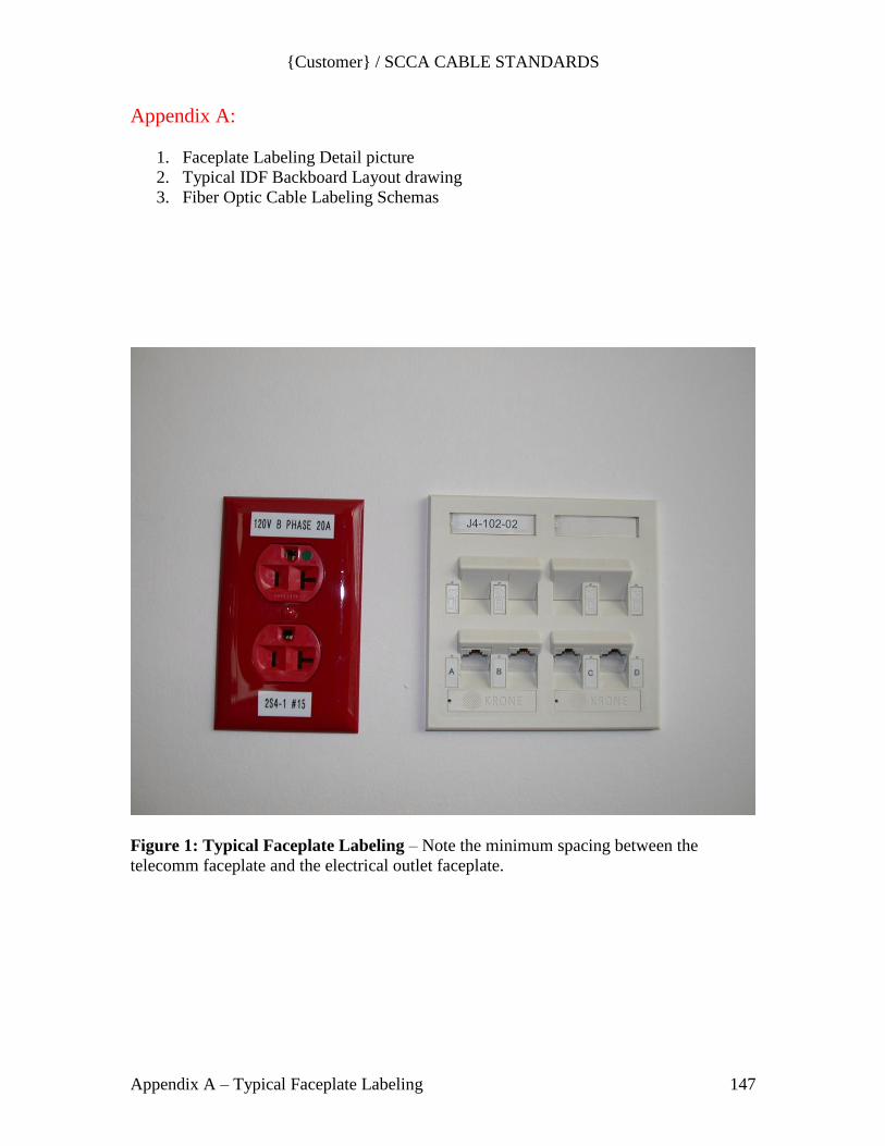
{Customer} / SCCA CABLE STANDARDS
Appendix A – Typical Faceplate Labeling 147
Appendix A:
1. Faceplate Labeling Detail picture
2. Typical IDF Backboard Layout drawing
3. Fiber Optic Cable Labeling Schemas
Figure 1: Typical Faceplate Labeling – Note the minimum spacing between the
telecomm faceplate and the electrical outlet faceplate.
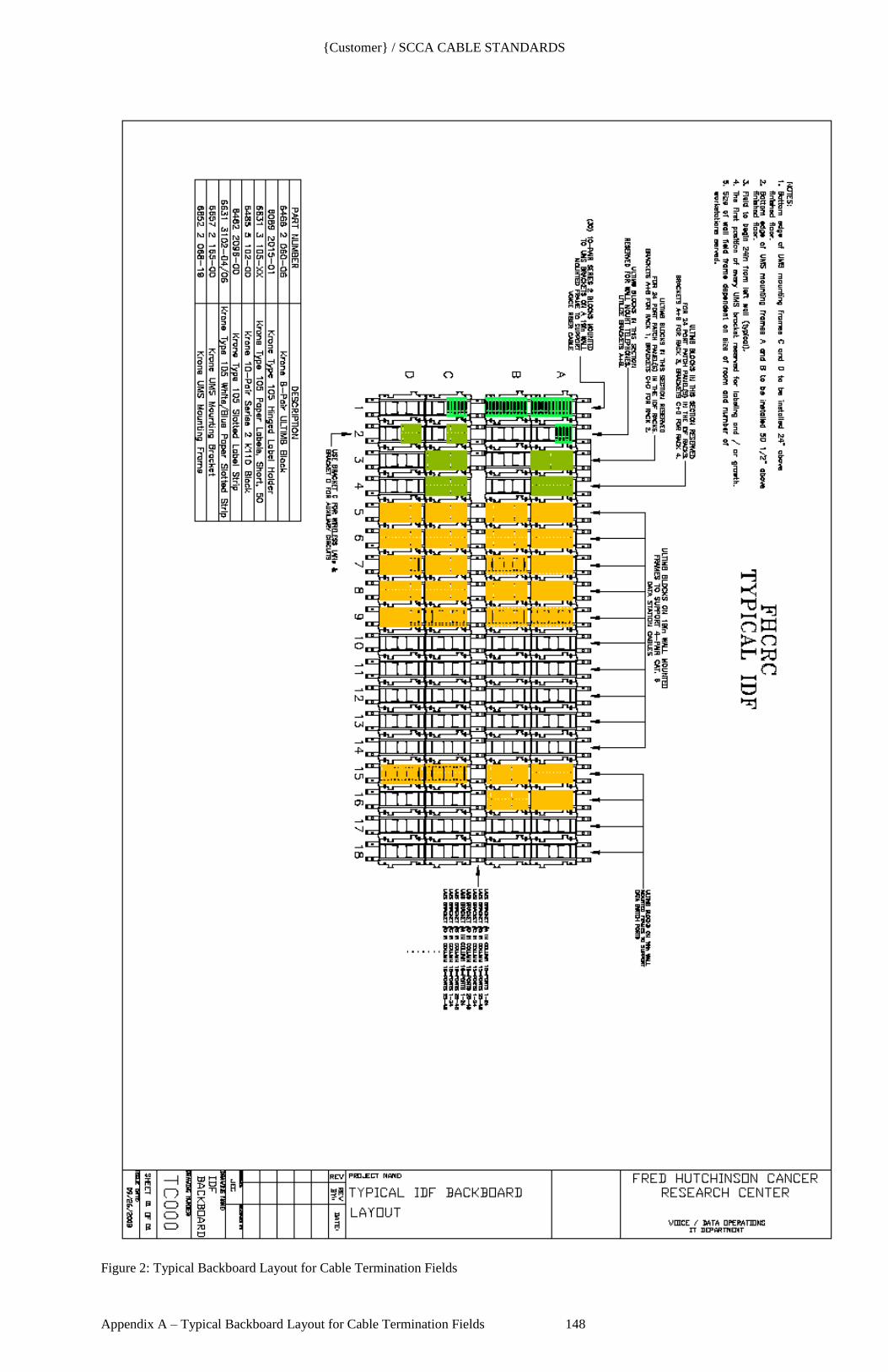
{Customer} / SCCA CABLE STANDARDS
Appendix A – Typical Backboard Layout for Cable Termination Fields 148
Figure 2: Typical Backboard Layout for Cable Termination Fields
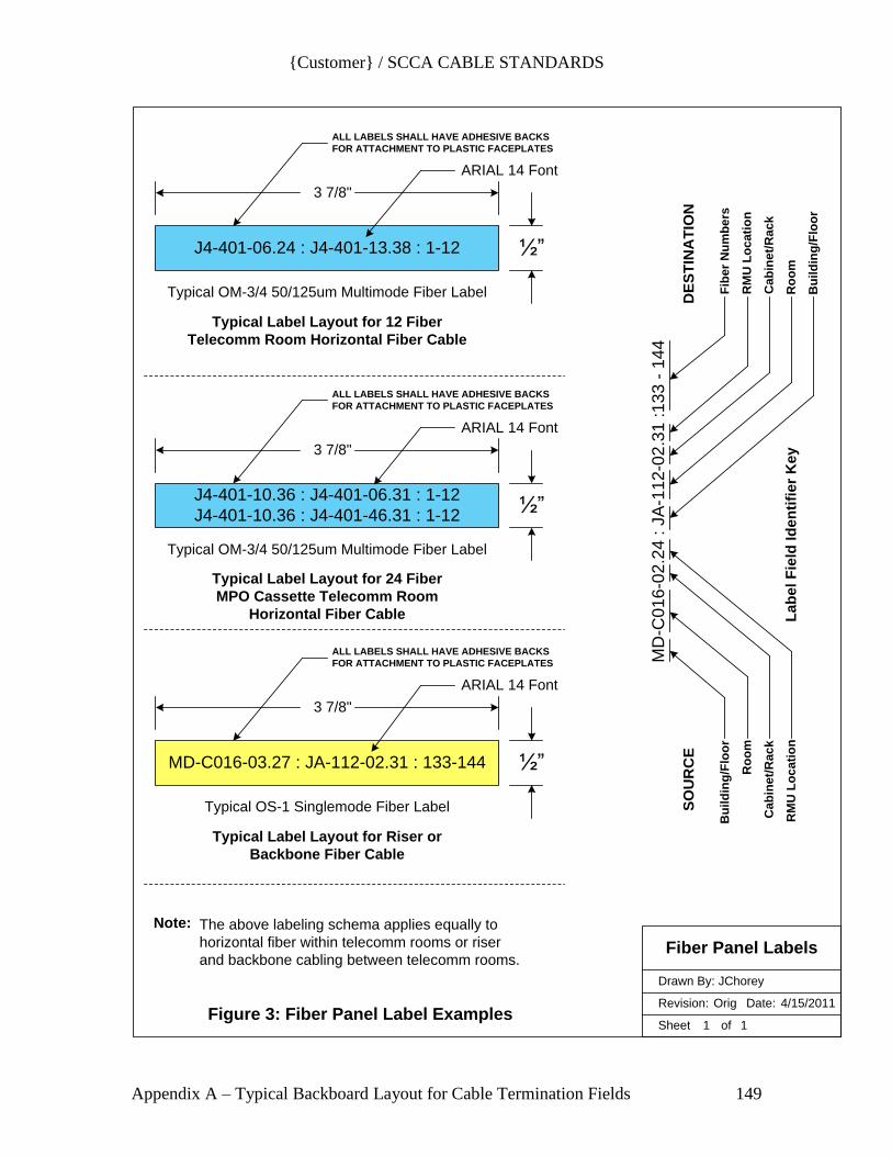
{Customer} / SCCA CABLE STANDARDS
Appendix A – Typical Backboard Layout for Cable Termination Fields 149
Sheet of
Revision: Date:
Drawn By: JChorey
J4-401-06.24 : J4-401-13.38 : 1-12
3 7/8"
½”
Typical OM-3/4 50/125um Multimode Fiber Label
ARIAL 14 Font
ALL LABELS SHALL HAVE ADHESIVE BACKS
FOR ATTACHMENT TO PLASTIC FACEPLATES
Fiber Panel Labels
1 1
Orig 4/15/2011
3 7/8"
½”
Typical OM-3/4 50/125um Multimode Fiber Label
ARIAL 14 Font
ALL LABELS SHALL HAVE ADHESIVE BACKS
FOR ATTACHMENT TO PLASTIC FACEPLATES
J4-401-10.36 : J4-401-06.31 : 1-12
J4-401-10.36 : J4-401-46.31 : 1-12
Typical Label Layout for 24 Fiber
MPO Cassette Telecomm Room
Horizontal Fiber Cable
3 7/8"
½”
Typical OS-1 Singlemode Fiber Label
ARIAL 14 Font
ALL LABELS SHALL HAVE ADHESIVE BACKS
FOR ATTACHMENT TO PLASTIC FACEPLATES
Typical Label Layout for Riser or
Backbone Fiber Cable
MD-C016-03.27 : JA-112-02.31 : 133-144
Typical Label Layout for 12 Fiber
Telecomm Room Horizontal Fiber Cable
Figure 3: Fiber Panel Label Examples
Bu
ild
ing
/Flo
or
Ro
om
Ca
bin
et/
Ra
ck
RM
U L
oc
ati
on
Bu
ild
ing
/Flo
or
Ro
om
Ca
bin
et/
Ra
ck
RM
U L
oc
ati
on
Fib
er
Nu
mb
ers
La
be
l F
ield
Id
en
tifi
er
Ke
y
MD
-C0
16
-02.2
4 :
JA
-11
2-0
2.3
1 :1
33
- 1
44
Note: The above labeling schema applies equally to
horizontal fiber within telecomm rooms or riser
and backbone cabling between telecomm rooms.
DE
ST
INA
TIO
NS
OU
RC
E

{Customer} / SCCA CABLE STANDARDS
End of Document