Embed Size (px)
Citation preview

June 6, 2011 Communications Infrastructure Cabling Services –ITB Addenda #1
• APPENDIX D, Revision 3.3, dated May 19, 2006, is replaced in its entirety, with APPENDIX D, Revision 9, dated April 2011, per the attached Technology Standards.
Technology Standards
Revision - 9 April 2011

TELECOMMUNICATION INFRASTRUCTURE STANDARDS
ii
Table of Contents INTRODUCTION ....................................................................................................................... 5 CONTRACTOR REQUIREMENTS ............................................................................................ 5 DEFINITIONS ............................................................................................................................ 5
A. Terms................................................................................................................................ 5 B. Abbreviations and Acronyms............................................................................................. 5
STANDARDS............................................................................................................................. 5 DESIGN REQUIREMENTS........................................................................................................ 6 TOPOLOGY............................................................................................................................... 6
A. Inter-Building Fiber Optic Cable ........................................................................................ 6 B. Intra-Building Fiber Optic Cable ........................................................................................ 7
Table 1 Fiber Transmission Performance............................................................................ 7 C. Inter-Building Multipair UTP .............................................................................................. 7 D. Intra-Building Multipair UTP .............................................................................................. 7
HORIZONTAL/STATION CABLE ............................................................................................... 7 Figure 1- Network Topology (VoIP) ..................................................................................... 8
TELECOMMUNICATION ROOM – OVERVIEW..................................................................... 8 A. TELECOMMUNICATIONS ROOMS.................................................................................. 8 B. MDF .................................................................................................................................. 9 C. BDF .................................................................................................................................. 9 D. IDF.................................................................................................................................... 9 E. Environmental Control......................................................................................................10 F. Telecommunication Racks ...............................................................................................10 G. Power Distribution............................................................................................................10 H. Plywood Backboard .........................................................................................................11 I. Through Wall Penetrations ................................................................................................11 J. Conduits ...........................................................................................................................11 K. Ladder Tray and cable support systems...........................................................................11 L. Service Entrance ..............................................................................................................11 M. Grounding........................................................................................................................12 N. Work space......................................................................................................................12 O. Four Post Racks ..............................................................................................................12 P. Lighting ............................................................................................................................12 Q. Access doors ...................................................................................................................12 R. Clearance and Ceiling height ...........................................................................................12 S. Flooring ............................................................................................................................12
TELECOMMUNICATIONS OUTLETS ......................................................................................13 A. Standard Telecommunications Outlet...............................................................................13 B. Classroom and Office Outlets...........................................................................................13 D. Wall Phone Outlet ............................................................................................................13 E. Labeling ...........................................................................................................................14
Figure 2- Sample Telecommunications Outlet Faceplate ...................................................14 Label Criteria for outlet coming from BDF, Rack 01, Patch Panel 01, and ports 05-08. ......14
ADMINISTRATION ...................................................................................................................14 A. Voice Connections ...........................................................................................................14 B. Data Connections.............................................................................................................14 C. Fiber Optic Jumpers.........................................................................................................15
LABELING AND DOCUMENTATION........................................................................................15

TELECOMMUNICATION INFRASTRUCTURE STANDARDS
iii
A. Inter-Building Backbone Cabling ......................................................................................15 B. Intra-Building Backbone Cabling ......................................................................................15 C. Faceplates .......................................................................................................................15 D. Horizontal Cabling............................................................................................................16
TESTING ..................................................................................................................................16 A. Fiber Optic Backbone.......................................................................................................16 B. UTP Backbone .................................................................................................................16 C. Horizontal/Station Cabling................................................................................................16
LOW VOLTAGE AS-BUILT DOCUMENTATION .......................................................................17 A. General .............................................................................................................................17
CABLING PATHWAYS .............................................................................................................17 A. Open Cabling ...................................................................................................................17 B. Conduits...........................................................................................................................17 C. Cable Tray .......................................................................................................................18 D. Fire Stopping ...................................................................................................................18
Figure 3 – Label for Firewall Penetrations ..........................................................................19 E. Surface Mounted Raceway ..............................................................................................19
WIRELESS ACCESS POINT ....................................................................................................20 A. General ............................................................................................................................20 B. Power...............................................................................................................................20 C. Wireless Access Point Locations .....................................................................................20
DIGITAL SIGNAGE...................................................................................................................20 A. Power Requirements........................................................................................................21 B. Conduit and Data Outlet ...................................................................................................21 C. Wall Support Backing.......................................................................................................21
CLASSROOM MEDIA STANDARDS ........................................................................................21 A. Media Equipped Classroom .............................................................................................21 B. Pathway Standards ..........................................................................................................21 C. Classroom Lighting Zone Diagram ...................................................................................22 AV Classroom Elevation Figures 1A and 1B..........................................................................23 AV Conference Room Elevation Figures 2A and 2B ..............................................................24 AV Classroom Layout Figure 3 ..............................................................................................25 AV Classroom Reflected Ceiling Plan Figure 4 ......................................................................26 AV Technology Podium Elevation Figures 5A and 5B ...........................................................27 AV Technology Desk Style Podium Elevation Figure 6 ..........................................................28 AV Wide Classroom View with Technology Podium Figure 7 ................................................29 AV Classroom View with Technology Podium Figure 8 .........................................................30 AV Video Conference Room Figures 9A and 9B ...................................................................31 APPENDIX A – INSIDE CONDUIT AND PATHWAY REQUIREMENTS ................................32 A. Conduit ............................................................................................................................32 B. Wireways .........................................................................................................................32 C. Pathway ...........................................................................................................................32 APPENDIX B – OUTSIDE PLANT CONDUIT AND VAULT DETAIL......................................33 A. Outside Plant Conduit .......................................................................................................33 B. Installation.........................................................................................................................33 C. Design Elements...............................................................................................................33 D. Vaults................................................................................................................................34 E. Loading Requirements: .....................................................................................................34 APPENDIX C – OUTSIDE CONDUIT SYSTEM AND VAULT INSTALLATION......................35 GUIDELINES.........................................................................................................................35 A. Vault Placement and Security ..........................................................................................35

TELECOMMUNICATION INFRASTRUCTURE STANDARDS
iv
B. Drainage ..........................................................................................................................35 C. Vault Racking and Space Allocations ...............................................................................35 D. Conduit Allocation and Fill Procedures.............................................................................35 APPENDIX D – PRE-APPROVED PRODUCT SET ..............................................................36 A. Approved Part Numbers. ...................................................................................................37 APPENDIX E – MAIN DISTRIBUTION FRAME (TYPICAL) ...................................................41 APPENDIX F – BUILDING DISTRIBUTION FRAME (TYPICAL) ...........................................42 APPENDIX G – INTERMEDIATE DISTRIBUTION FRAME (TYPICAL) .................................43 APPENDIX H – MDF/BDF BAYFACE (TYPICAL) .................................................................44 APPENDIX I – IDF BAYFACE (TYPICAL) .............................................................................45 APPENDIX J – BONDING AND GROUNDING DETAIL ........................................................46 A. Bonding............................................................................................................................46
Table 2 – Bonding Conductor Sizing ..................................................................................46 B. Grounding ........................................................................................................................47 C. Labeling, Color-Coding, and Marking ...............................................................................47
Figure 4: Label for Grounding and Bonding Conductors.....................................................47 D. Telecommunications Main Grounding Busbar (TMGB) ....................................................47 E. Bonding to a Panel Board ................................................................................................48 F. Connections to the Telecommunications Main Grounding Busbar ....................................48 G. Installation Requirements ................................................................................................48 H. Bonding Conductor for Telecommunications ....................................................................48 I. Telecommunications Bonding Backbone (“TBB”)...............................................................49 J. Bonding and Sizing the TBB .............................................................................................49 K. Telecommunications Grounding Busbar...........................................................................49 L. Bonding to the TGB ..........................................................................................................50 M. Bonding to the Metal Building Frame ...............................................................................50 APPENDIX K - GLOSSARY .................................................................................................51

TELECOMMUNICATION INFRASTRUCTURE STANDARDS
Portland Community College Technology Standards – Revision 9
April 2011 Page 5
INTRODUCTION This document addresses telecommunications infrastructure standards. The requirements specified are based on current Portland Community College (PCC) and industry standards. This document will be used by PCC staff and consulting Architects, Engineers, and Designers working for the College on projects in new or existing facilities requiring the design and installation of telecommunications distribution systems. This guide and accompanying specifications serve as the basis for the construction documents to ensure uniformity and consistency of the telecommunication systems installed. Any exceptions to these standards must be reviewed and approved by the Technical Services Division Manager on a per project basis.
CONTRACTOR REQUIREMENTS Workmanship shall be of the best quality and competent and experienced low voltage electricians shall be employed and shall be under the direct supervision of a competent and experienced foreman.
Cabling vendor must be a certified Panduit installer with a current Panduit license to install. At least 50% of the Cabling contractor's personnel working on the project must be certified installers. Panduit certification and warranty testing results will be provided to Architect, Owner or Authorized Representative.
DEFINITIONS
A. Terms
The terms “College” and “Owner” as used in this document represent Portland Community College.
B. Abbreviations and Acronyms
The college will utilize the following terminology when referencing telecommunications rooms and facilities, specifically:
• Main Distribution Frame or MDF – An entrance to a campus for both public and private network
service cables (including wireless) including the entrance point of the building and continuing to the entrance room or space. The MDF also serves as a BDF.
• Building Distribution Frame (BDF) –An environmentally controlled centralized space for telecommunications equipment that usually houses a point of entry from the main building cross- connect.
• Intermediate Distribution Frame (IDF) – An environmentally controlled enclosed architectural space designed to contain telecommunications equipment, cable terminations, or cross-connect cabling.
• Telecommunications Room – as used in this document refers to the MDF, BDF, or IDF in generic terms, as a point for termination of telecommunications cables.
STANDARDS All telecommunication distribution designs shall be based on and shall comply with the following industry standards.
• ANSI/TIA/EIA-526-14-A-1998. Optical Power Loss Measurements of Installed Multimode Fiber Cable Plant-OFSTP-14A.
• ANSI/TIA/-568-C: Generic Telecommunications Cabling for Customer Premises

TELECOMMUNICATION INFRASTRUCTURE STANDARDS
Portland Community College Technology Standards – Revision 9
April 2011 Page 6
• ANSI/TIA/-568-C: Commercial Building Telecommunications Cabling Standard • ANSI/TIA/EIA-568-C: Commercial Building Telecommunications Cabling Standard, Part 2:
Balanced Twisted Pair Cabling • ANSI/TIA/ -568-C: Optical Fiber Cabling Components Standard, June 2008 • TIA -569-B: Commercial Building Standard for Telecommunications Pathways and Spaces • ANSI/TIA/EIA-598-Color Coding of Fiber optic Cables. • ANSI/TIA/EIA-606-A. The Administration Standard for the Telecommunications infrastructure of
Commercial Building • ANSI-J-STD-607-A-2002. Commercial Building Grounding and Bonding Requirements for
Telecommunications • ANSI/TIA/EIA-758. Customer Owned Outside Plant Telecommunications Cabling Standard • NFPA-70, National Electric Code (NEC)
All above referenced documents are to be latest version, including addendum, in publication at time work is requested.
In addition to the above telecommunications standards, all design documents shall comply with codes and requirements of the local Authority Having Jurisdiction (AHJ).
DESIGN REQUIREMENTS The telecommunication distribution system design shall provide a cost effective standards based structured cabling system that is capable of supporting current and future voice, video and data applications over a common cabling plant. The system shall support at a minimum IEEE 802.3 Ethernet applications including 10Base-T, 100Base-TX, 1000Base-T, and 1000Base-TX in the horizontal link and 10GBase-x in the backbone connections.
TOPOLOGY The telecommunication distribution system shall be a hierarchical star topology consisting of backbone cables connecting the Main Distribution Frame (“MDF”) to Building Distribution Frame (“BDF”) or Intermediate Distribution Frame (“IDF”). Horizontal cables shall be installed from each Telecommunication Outlet (“TO”) to the nearest telecommunications room serving that area of the building.
A. Inter-Building Fiber Optic Cable
The inter-building fiber optic cable will be a composite construction with 48 strands of 50/125μm laser optimized multimode and 12 strands of single mode combined under a common jacket. Fiber shall be tight buffer and jacket ratings shall be suitable for indoor-outdoor placement without need for fan-out assemblies prior to termination within a building.
The fiber will meet the specifications listed in ANSI/TIA/EIA 568-C and the transmission performance parameters listed in Table 1.
Inter-building fiber cables shall be installed within 1" orange inner duct. Coordinate with TSS Department for exact fiber requirements.
The fiber optic strands shall be terminated with LC type connectors. The LC will have a ceramic ferule and will be attached to each fiber strand with either a heat cure or anaerobic type epoxy.
In large buildings with more than 4 stories, containing a BDF and three (3) IDFs, an additional 12 strands of 50/125μm multimode will be required for each additional IDF in the building if such may be accomplished within the 550 meter limitation noted below.

TELECOMMUNICATION INFRASTRUCTURE STANDARDS
Portland Community College Technology Standards – Revision 9
April 2011 Page 7
B. Intra-Building Fiber Optic Cable
The intra-building fiber optic cable will be 12 strands 50/125μm multimode fiber. Fiber shall be tight buffer and jacket ratings shall be suitable for application. The fiber will meet the specifications listed in ANSI/TIA/EIA 568-C and the transmission performance parameters listed in Table 1.
In new construction or substantial remodel of an existing facility, intra-building shall be 12 strands 50/125µm Laser Enhanced multimode utilizing factory assembled pre-terminated MTP connectors. Rating shall be OFNP.
All intra-building fiber cables shall be installed within 1" orange inner duct. The distance between the BDF and the IDF shall not exceed 550 m (1604 ft).
The fiber optic strands shall be terminated with LC type connectors. The LC will have a ceramic ferule and will be attached to each fiber strand with either a heat cure or anaerobic type epoxy.
Optical fiber cable type Wavelength (nm) Maximum attenuation (dB/km) 50/125µm multimode 850 3.0 50/125µm multimode 1300 1.5 Single mode 1310 1.0 Single mode 1550 1.0
Table 1 Fiber Transmission Performance C. Inter-Building Multipair UTP
The Inter-Building backbone copper cables shall be a multipair, Category 3 cable from the campus MDF to the building BDF. The cable shall consist of an ASP sheath with 24 AWG solid- copper conductors encapsulated with water blocking gel filling compound for moisture protection. The multipair UTP will meet or exceed the mechanical and transmission specifications of ANSI/TIA/EIA-568-C. A minimum 25 pair UTP shall be installed per Telecommunications Room.
In large buildings with more than 4 stories, containing a BDF and three (3) IDFs, an additional 25 pair of category 3 backbone cable will be required for each additional IDF in the building. Coordinate with TSS Department for exact backbone copper requirements.
D. Intra-Building Multipair UTP
Intra-building copper backbone shall be 25 pair 24 AWG. Jacket shall be suitably rated for application but in no case less than CMR. The cable will meet or exceed the performance and transmission specifications of ANSI/TIA/EIA-568-C requirements for Category 3.
In large buildings with more than 4 stories, containing a BDF and three (3) IDFs, an additional 25 pair of category 3 backbone cable will be required for each additional IDF in the building. Coordinate with TSS Department for exact backbone copper requirements.
HORIZONTAL/STATION CABLE
The horizontal station cables shall be 100 ohm, 4-pair; Blue category 6 plenum rated UTP cables. The length of each horizontal cable shall not exceed 90 meters (295 feet) regardless of medium. One end of a horizontal cable shall terminate at the Telecommunications Outlet. The other end of a horizontal cable shall terminate on a rack mounted modular patch panel located

TELECOMMUNICATION INFRASTRUCTURE STANDARDS
Portland Community College Technology Standards – Revision 9
April 2011 Page 8
Network Hardware w/POE
Fiber Patch Panel
Fiber Patch Panel
Network Hardware w/PoE
Network Hardware w/POE
Fiber Patch Panel
in the nearest Telecommunication Room. Copper based patch panels shall typically be 48 ports with 24 ports as specified by PCC project team.
All horizontal station cables will have a 10' service loop coiled at the workstation end of the cable to support future cable relocations.
Utility Copper
Modular Patch Panels
Horizontal (Station) Cable
Main Distribution Frame
(MDF) Building Distribution Frame
(BDF)
110 Wiring Blocks 110 Wiring Blocks
Inbound Services
Telecommunications Room
(IDF)
Network Core
Fiber Patch Panel
VoIP Platform
Utility Copper
Utility Copper
Modular Patch
Panels
Horizontal (Station) Cable
Modular Patch
Panels
Telecommunications Room (IDF)
Horizontal (Station) Cable
Figure 1- Network Topology (VoIP) TELECOMMUNICATION ROOM – OVERVIEW
The term “Telecommunications Room” is defined spaces where telecommunications cables are terminated and cross connected to appropriate resources. A finer definition and exacting operation criteria are provided below for spaces used to terminate cable, cross connect telecommunications circuits and install various active electronic components.
A. TELECOMMUNICATIONS ROOMS
A Telecommunication Room (TR) is a dedicated, secure, and environmentally controlled space used to terminate telecommunications cabling and house connecting hardware and networking equipment. There are several types of Telecommunications Rooms, specifically:

TELECOMMUNICATION INFRASTRUCTURE STANDARDS
Portland Community College Technology Standards – Revision 9
April 2011 Page 9
• Main Distribution Frame (MDF) - There will be one (1) MDF at each PCC campus or
center. The MDF serves as the demarcation point for service providers and PCC. All external telecommunications service providers (voice, video and data) will hand off their services to PCC at the demarcation point established in the MDF. The MDF also serves as the central point that connects inter-building cables. The MDF houses the core telephone and network equipment used to communicate between buildings, campuses or centers, and the public switched network. The MDF will serve as an IDF for all voice, data, and video connections with-in 90 meters of the MDF.
• Building Distribution Frame (BDF) - There will be one (1) BDF for each building at a campus or center. The BDF serves at the point of entry for inter-building cables. The BDF will have intra-building connections of fiber, copper, between itself and all IDF(s) in a building. The BDF will serve as an IDF for all voice, data, and video connections with- in 90 meters of the BDF. The BDF houses the network and video equipment used to support voice, data and video in the building.
• Intermediate Distribution Frame (IDF) - A building will have one or more IDF’s if the building has more than one floor or if the distance between the BDF and longest horizontal (station) cable run from the BDF exceeds 90 meters. An IDF provides the voice connection and the data and video connection(s) to an office, classroom, lab, common area, or work space in a building. The IDF houses the equipment used to support voice, data and video in a section of a building.
B. MDF
At a minimum every College educational or administrative facility shall have a MDF. Where the size of the facility dictates, IDFs shall be provided. The MDF will serve as the connection point to the College’s Wide Area Network (“WAN”) and the service entrance facility and demarcation point for Telco and alternate service providers.
The MDF will also house the voice system, security, access control and video distribution head ends. It is imperative that the MDF be sized adequately to accommodate each of these systems. The minimum recommended MDF size in new construction projects shall never be smaller than 20' x 30' (600 square feet). The MDF will be located on the first floor.
C. BDF
The BDF shall be centrally located within a building to minimize horizontal cable lengths and the number of IDFs required. The BDF shall be located on the first floor, and shall be dedicated to the telecommunications function and related support facilities. BDF size in new construction projects shall never be smaller than 15' x 20' (300 square feet) with two horizontal wall dimensions being no less than 15 feet. The BDF will be larger in buildings over 60,000 square feet.
The TR should not be shared with electrical installations other than those for telecommunications. Equipment not related to the support of the telecommunications room (e.g., piping, ductwork, pneumatic tubing, etc.) shall not be installed in, pass through, or enter the Telecommunications Rooms.
D. IDF
In cases where horizontal cabling lengths exceed 90 meters, an Intermediate Distribution Frame (IDF) is required. The IDF shall meet all of the environmental conditions specified for a BDF in regard to HVAC and power. The IDF shall provide cross connect and interconnect facilities between horizontal cabling serving a portion of the facility and the backbone cabling to the BDF.

TELECOMMUNICATION INFRASTRUCTURE STANDARDS
Portland Community College Technology Standards – Revision 9
April 2011 Page 10
The IDF shall be a dedicated space. The minimum size of an IDF shall be 10’ x 15’ (150 square feet). If additional racks are required in an IDF to provide mounting space for the required hardware and equipment then the IDF shall be sized to accommodate the racks necessary and provide 3’ of clearance in front of, behind and on one end of the racks.
E. Environmental Control
Environmental control systems shall be provided to the TR on a 24 hours-per-day, 365 days- per-year basis to monitor and maintain acceptable temperature and humidity levels. The systems shall provide cooling to maintain a temperature range of 64°F to 75°F with 30% to 50% relative humidity.
A neutral pressure shall be maintained with a minimum of one air exchange per hour.
At a minimum, the HVAC system must be capable of removing 7,000 BTU per hour from the telecom room.
If a standalone air conditioning unit is used within the TR, it may be wall mounted or hung from the ceiling. If hung from the ceiling the bottom of the unit must be a minimum of 8’6” above the finished floor. The air conditioning unit shall not be located over the telecommunication equipment. The air conditioning unit shall serve only the TR and a thermostat to control the unit shall be located in the TR. The mechanical condensate piping shall be located away from racks and equipment and shall drain outside the TR. The air conditioning unit shall be capable of and configured for automatic restart following a power failure.
F. Telecommunication Racks
The BDF shall contain two or more 19” x 7’ freestanding telecommunications equipment racks and a least one 4 post rack for mounting patch panels, cable management and networking equipment such as routers and switches. Racks shall be arranged side by side in a row to facilitate routing of cabling between patch panels and the networking equipment. The quantity of racks shall be determined by quantity and type of patch panels and networking equipment required. The racks shall be ganged with 10” wide double sided vertical management hardware placed between the racks and 6” vertical wire management at the outside ends of the row of racks. Racks shall be placed in a manner that will allow a minimum of 3 feet of clearance from the front, plus 42 inches for the rack and equipment with 3 feet clearance in rear and on one side. If one mounting rail of the rack is placed against a wall, the mounting rail shall be no closer than 6” to the wall to allow room for vertical management.
G. Power Distribution
Minimum standard is below. Specifications will call out power distribution as required on a project basis.
• Each TR shall be equipped with a rack mounted Uninterruptible Power Supply (UPS) provided and installed by the Contractor. UPS shall be sized to accommodate projected equipment load with a thirty percent (30%) expansion factor. UPS input power will be a 208 volt, 30/40/60/100 amps or as specified mounted at the bottom of the equipment rack the vertical wire manager.
• Additional duplex convenience outlets shall be placed at 6-foot intervals around the perimeter of the room at 18 inches above the finished floor.
• Provide two horizontal power strips for each freestanding rack. The power strips shall have a minimum of nine (9) outlets, rated at 20 amps. See Appendix D for Approved Product Manufacturer..
TELECOMMUNICATION INFRASTRUCTURE STANDARDS
Portland Community College Technology Standards – Revision 9
April 2011 Page 11
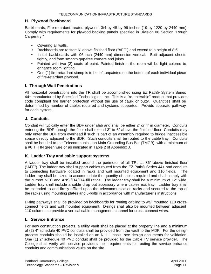
H. Plywood Backboard
Backboards; Fire-retardant treated plywood, 3/4 by 48 by 96 inches (19 by 1220 by 2440 mm). Comply with requirements for plywood backing panels specified in Division 06 Section "Rough Carpentry."
• Covering all walls. • Backboards are to start 6" above finished floor (“AFF”) and extend to a height of 8.6'. • Install backboards with 96-inch (2440-mm) dimension vertical. Butt adjacent sheets
tightly, and form smooth gap-free corners and joints. • Painted with two (2) coats of paint. Painted finish in the room will be light colored to
enhance room lighting. • One (1) fire-retardant stamp is to be left unpainted on the bottom of each individual piece
of fire-retardant plywood. I. Through Wall Penetrations
All horizontal penetrations into the TR shall be accomplished using EZ Path® System Series 44+ manufactured by Specified Technologies, Inc. This is a “re-enterable” product that provides code compliant fire barrier protection without the use of caulk or putty. Quantities shall be determined by number of cables required and systems supported. Provide separate pathway for each system.
J. Conduits
Conduit will typically enter the BDF under slab and shall be either 2” or 4” in diameter. Conduits entering the BDF through the floor shall extend 3” to 6” above the finished floor. Conduits may only enter the BDF from overhead if such is part of an assembly required to bridge inaccessible space directly adjacent to the BDF. Such conduits shall be routed to the cable tray. Conduits shall be bonded to the Telecommunication Main Grounding Bus Bar (TMGB), with a minimum of a #6 THHN green wire or as indicated in Table 2 of Appendix J.
K. Ladder Tray and cable support systems
A ladder tray shall be installed around the perimeter of all TRs at 86” above finished floor (“AFF”). The ladder tray shall support cables routed from the EZ Path® Series 44+ and conduits to connecting hardware located in racks and wall mounted equipment and 110 fields. The ladder tray shall be sized to accommodate the quantity of cables required and shall comply with the current NEC and ANSI/TIA/EIA fill ratios. The ladder tray shall be a minimum of 12” wide. Ladder tray shall include a cable drop out accessory where cables exit tray. Ladder tray shall be extended to and firmly affixed upon the telecommunication racks and secured to the top of the racks using mounting plates and J-bolts in accordance with manufacturer’s instructions.
D-ring pathways shall be provided on backboards for routing cabling to wall mounted 110 cross- connect fields and wall mounted equipment. D-rings shall also be mounted between adjacent 110 columns to provide a vertical cable management channel for cross-connect wires.
L. Service Entrance
For new construction projects, a utility vault shall be placed at the property line and a minimum of (2) 4” schedule 40 PVC conduits shall be provided from the vault to the MDF. For the design process conduits should be installed on an N + 1 basis, see design documents for validation. One (1) 2” schedule 40 PVC conduit shall be provided for the Cable TV service provider. The College shall verify with service providers their requirements for routing the service entrance conduits and communications vaults on the site.

TELECOMMUNICATION INFRASTRUCTURE STANDARDS
Portland Community College Technology Standards – Revision 9
April 2011 Page 12
Innerduct shall be installed in all four inch entrance conduits. Size and quantity of innerduct will be specified when initial service is requested.
A minimum of 4’ x 4’ space shall be provided on the backboard for each service provider. M. Grounding
In new construction, or substantial remodel, it is the responsibility of the Electrical Engineer to specify a Telecommunications Bonding Backbone (“TBB”) that complies with the above referenced Standard. It is typically a 1/0 (or larger) bare stranded copper cable that is bonded to the Telecommunications Main Grounding Buss bar (“TMGB”) at the BDF and to a Telecommunications Grounding Buss bar (TBB) at each of the IDFs. The initial component of this work is accomplished by the electrical contractor as part of the rough-in package with the actual grounding bars being installed as a part of the final trim-out. All racks, ladder tray and conduit shall be grounded with #6 AWG copper conductor to the TMGB. Refer to Appendix J for further detail.
N. Work space
The MDF shall have a dedicated work space that allows a 30" X 60" work surface. The work space shall have a minimum of one dedicated 120 volt 20 amps, double duplex receptacle. The work space shall have a Telecommunications Outlet configured with a minimum of four jacks. All TRs shall be equipped with a wall phone.
O. Four Post Racks
Space shall be allocated in the MDF for four post racks. The four post racks shall be floor- mounted and shall require a 24” x 48” floor space and 48” front and 36” rear clearance for servicing the equipment. PCC staff shall be consulted as the number of spaces to be reserved in the MDF on a building-by-building basis.
P. Lighting
Lighting shall be a minimum of 50 foot candles, (500 lumens) measured 3 feet above the finished floor. Placement of lighting shall be coordinated to avoid obstacles such as cable trays that obstruct light.
Q. Access doors
Doors shall open out from Telecommunications Rooms (MDF, BDF, and IDF) wherever possible and shall be a minimum of 36" wide and 80" high. Room access will be controlled by card readers. Door will be fitted with a lock that can override the card reader, which is keyed as specified by TSS for Telecommunications Rooms. Doors shall be located in hallways or other common areas. In no case shall the door be located in another building occupants designated space.
R. Clearance and Ceiling height
Minimum clearance height within a Telecommunications Room shall be 8’, 6”. False ceilings (t- bar ceilings, ceiling grids, etc.) shall not be installed in Telecommunications Rooms.
S. Flooring
The floors for new construction will be sealed concrete. On remodel projects the floors, walls, and ceilings shall be sealed to reduce dust. Flooring materials with anti-static properties - carpet is not acceptable for Telecommunications Rooms.

TELECOMMUNICATION INFRASTRUCTURE STANDARDS
Portland Community College Technology Standards – Revision 9
April 2011 Page 13
TELECOMMUNICATIONS OUTLETS The term “Telecommunications Outlet” (TO) encompass a broad set of jacks and plugs locations where physical connectivity is provided for a network device. Exacting criteria by type is provided below.
A. Standard Telecommunications Outlet
A standard wall telecommunications outlet shall be a flush mount faceplate containing three 3 telecommunication jacks. Classroom podium outlets require four (4) telecommunication jacks. Each telecommunications device shall be a Category 6, 8-pin modular jack wired in a T568A pinout. Coordinate with TSS Department for exact outlet requirements.
The standard Telecommunications Outlet shall be housed in a recessed 2-1/8” deep x 4” square outlet box flush to the wall with 5/8” single gang mud ring. A one inch conduit and pull string shall be installed from the outlet box to an accessible ceiling space. Appropriately rated bushings shall be installed on the end of the conduit stubbing into the accessible ceiling space.
The standard faceplate shall be a vertical single gang frame manufactured from high-impact thermoplastic material. The faceplate shall be available in 4 and 6 port configurations. Faceplates shall be mounted to recessed outlet boxes in the wall. Faceplates must be of a design that allows permanent labeling that remains intact while allowing removal and reinstallation of the plate.
B. Classroom and Office Outlets
Standard classrooms require one (1) standard floor box outlet and one (1) standard ceiling box outlet. Refer to Figure 2.
Offices require two (2) standard wall outlets on opposite walls in the room. Outlet locations are to be coordinated with furniture layout on drawings.
Surface Mounted Outlet In retrofit and remodel projects where cabling cannot be routed within the wall, the outlet shall be surface mounted. Where the outlet is surface mounted, the cabling to the outlet shall be installed within a surface raceway. The size of the raceway shall be specified on a case by case basis, but at a minimum, the raceway shall have a one inch cross sectional area.
Telecommunication Outlets shall be surface mount outlet boxes compatible with the raceway specified. The surface mount outlet boxes shall be deep versions with a divider wall to maintain separation of power and data cables and allow for termination of both services in one outlet box. For larger raceways a device bracket shall be available for mounting of devices within the raceway.
Where surface raceway is used, the faceplate shall be mounted on a single gang surface mount boxes. Faceplates must be of a design that allows permanent labeling that remains intact while allowing removal and reinstallation of the plate.
D. Wall Phone Outlet
Wall phone outlets shall be a flush or surface mounted to a single gang outlet box. The outlet shall be mounted so the highest operable mechanism is in compliance with ADA requirements. The faceplate shall be stainless steel with keystone opening capable of accepting an 8-pin modular insert. Faceplate shall be equipped with studs for mounting a wall phone.

TELECOMMUNICATION INFRASTRUCTURE STANDARDS
Portland Community College Technology Standards – Revision 9
April 2011 Page 14
E. Labeling
All telecommunication outlets shall be labeled in accordance with TIA/EIA-606-A and conform to Section 13 below. The labels shall be typed or machine-engraved. The label shall identify the Telecommunication Room, patch panel and port on the patch panel that the horizontal cable terminates. Telecommunication outlet labels shall be installed in a manner that does not cover the faceplate attachment screws.
Figure 2- Sample Telecommunications Outlet Faceplate
Label Criteria for outlet coming from BDF, Rack 01, Patch Panel 01, and ports 05-08. ADMINISTRATION
A. Voice Connections
The voice ports will be connected to the active equipment using RJ45 to RJ45 modular patch cords. All patch cables will be red factory terminated category 6 and installed to length (maximum 1’ of slack).
B. Data Connections
The data ports will be connected to the backbone termination field using RJ45 to RJ45 modular patch cords. All patch cords will be [white] factory terminated category 6 and installed to length (maximum 1’ of slack). Patch cords and station cable will be equal in Category to the installed cable and be stranded unshielded twisted pair (UTP). Patch cords will be used between patch panels and active electronics. Lengths will be kept to a minimum while remaining with standard, manufactured lengths. Likewise, station cords will be stranded unshielded twisted pair in lengths that allow proper routing and minimize coils or slack cable length. In no case will station cords be run across open spaces or taped to the floor.

TELECOMMUNICATION INFRASTRUCTURE STANDARDS
Portland Community College Technology Standards – Revision 9
April 2011 Page 15
C. Fiber Optic Jumpers
Install factory terminated fiber optic duplex jumpers between equipment and fiber panels. A PCC representative shall determine the actual size and configuration of the jumpers based on the network design (SC to SC, SC to ST, ST to ST, LC to LC etc.).
LABELING AND DOCUMENTATION Labels shall be affixed in permanent manner using sleeve or wrap around methods. All labels shall be machine printed with a minimum font size of 12 with black lettering on white background. Refer to Figure 2.
A. Inter-Building Backbone Cabling
Backbone cables shall be labeled within 24” of the cable termination. Labels will contain information clearly identifying both ends of the run using the following nomenclature: MDF to BBB,RRR,TT,CCC, where: MDF = Main Distribution Frame (Only one per campus or center.) BBB = Three (3) letter building designation RRR = Destination Room in the Building (BDF, IDF1, IDF2, IDF3, etc) TT = Type of Cable (MM for Multimode, SM for Single Mode, CP for Copper, CX for Coaxial) CCC = Pair or Strand Count (12 pair, 24 pair, 48 pair, 300 pair, etc.) Example 1 - A 48 pair of Multimode fiber between the Main Distribution Frame and Health Technology (HT) Building Telecommunications Room would have the following label:
MDF to HT,BDF,MM,48 Example 2 - A12 pair single mode fiber between the Main Distribution Frame and Health Technology (HT) Building BDF would have the following label:
MDF to HT,BDF,SM,12 B. Intra-Building Backbone Cabling
Intra-building cables shall be labeled within 24” of the cable termination. Labels will contain information clearly identifying both ends of the run using the following nomenclature: From xx to RRR where: xx= Main Telecommunications Room or Telecommunications Room RRR = Destination Room in the Building (IDF1, IDF2, IDF3, etc) For example, a 12 pair Multimode fiber between the BDF and IDF2 in a building
From BDF to IDF2 C. Faceplates
Faceplates labels shall be provided to clearly identify each location with the following information: IDF.RN.PP.NN where, IDF = Telecommunications Room servicing the outlet RN = Rack number within the IDF PP = Patch panel within the rack NN = port number (1-48) within the patch panel For example, a faceplate housing four jacks supported from Telecommunications Room 1, third rack, second patch panel, first four ports would be labeled:
1.03.02.01-04
TELECOMMUNICATION INFRASTRUCTURE STANDARDS
Portland Community College Technology Standards – Revision 9
April 2011 Page 16
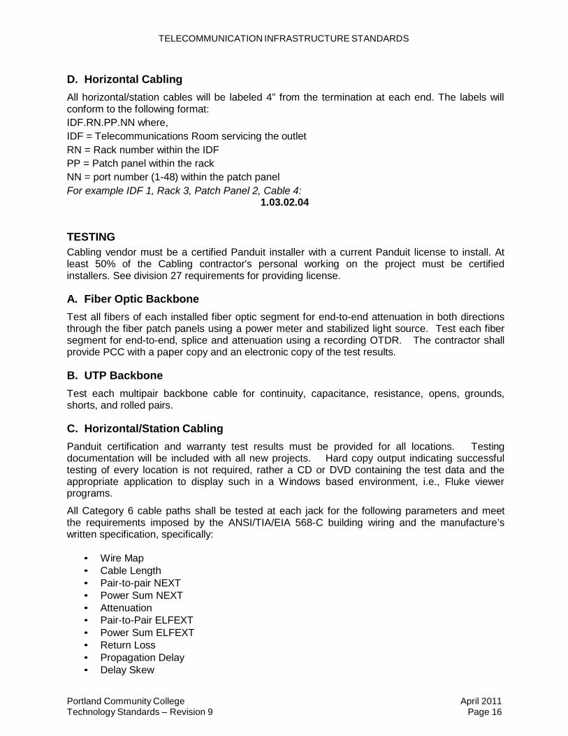
D. Horizontal Cabling
All horizontal/station cables will be labeled 4” from the termination at each end. The labels will conform to the following format: IDF.RN.PP.NN where, IDF = Telecommunications Room servicing the outlet RN = Rack number within the IDF PP = Patch panel within the rack NN = port number (1-48) within the patch panel For example IDF 1, Rack 3, Patch Panel 2, Cable 4:
1.03.02.04 TESTING Cabling vendor must be a certified Panduit installer with a current Panduit license to install. At least 50% of the Cabling contractor's personal working on the project must be certified installers. See division 27 requirements for providing license.
A. Fiber Optic Backbone
Test all fibers of each installed fiber optic segment for end-to-end attenuation in both directions through the fiber patch panels using a power meter and stabilized light source. Test each fiber segment for end-to-end, splice and attenuation using a recording OTDR. The contractor shall provide PCC with a paper copy and an electronic copy of the test results.
B. UTP Backbone
Test each multipair backbone cable for continuity, capacitance, resistance, opens, grounds, shorts, and rolled pairs.
C. Horizontal/Station Cabling
Panduit certification and warranty test results must be provided for all locations. Testing documentation will be included with all new projects. Hard copy output indicating successful testing of every location is not required, rather a CD or DVD containing the test data and the appropriate application to display such in a Windows based environment, i.e., Fluke viewer programs.
All Category 6 cable paths shall be tested at each jack for the following parameters and meet the requirements imposed by the ANSI/TIA/EIA 568-C building wiring and the manufacture’s written specification, specifically:
• Wire Map • Cable Length • Pair-to-pair NEXT • Power Sum NEXT • Attenuation • Pair-to-Pair ELFEXT • Power Sum ELFEXT • Return Loss • Propagation Delay • Delay Skew

TELECOMMUNICATION INFRASTRUCTURE STANDARDS
Portland Community College Technology Standards – Revision 9
April 2011 Page 17
LOW VOLTAGE AS-BUILT DOCUMENTATION
A. General
As-built documentation for telecommunications infrastructure is required upon completion of a project. For all projects, the following are the minimum documentation requirements:
• Complete plans of the new facility showing locations for Telecommunications Room(s)
and Telecommunications Outlets. • All Telecommunications Outlet locations will be annotated with the above detailed label
criteria. This document will be provided electronically in PDF format as well as hard copy.
• Cable routing showing the pathway(s) in the facility and the point of connection to the outside plant conduit system. This will include information on the number and sizes of each conduit. This document will be provided electronically in PDF format as well as hard copy and may be combined with the above as a separate layer.
CABLING PATHWAYS Installation of Raceways/Pathways for telecommunication distribution systems shall be in accordance with applicable portions of TIA-569-B. Horizontal cabling shall be routed from each Telecommunication Outlet to an IDF using a combination of boxes, conduit, open cabling supports and cable tray. In new construction, cabling pathways shall be concealed in walls, casework, concrete slabs and above ceilings whenever possible. In renovations to existing spaces, the horizontal and backbone cabling may be routed in surface raceway when no other cost effective options exist.
Spare conduits shall be included as a part of any construction that entails “hard ceiling” to allow future placement of cables without disturbing the ceiling. A minimum of two, 4” conduits shall be placed in areas where hard ceilings extend beyond four feet from accessible spaces. Conduits are to be labeled as “Telecommunications Spare” and fire stopped as per requirements of the Authority Having Jurisdiction (AHJ).
A. Open Cabling
Horizontal cabling may be routed using open cabling supports above accessible ceilings, crawl spaces, mechanical attics and similar spaces when cable tray is not available. Open cabling supports shall be installed parallel or at right angles to the building structure and shall be permanently anchored to building structure or substrates using beam clamps, drop wire or threaded rod hanger brackets. Open cabling supports shall be J-hook type cable supports with an open-top and wide base designed for supporting telecommunications cabling. J-hook supports shall be spaced no further than 48” apart and shall be sized in accordance with manufacturer’s recommendations for quantity of cables supported. Fiber optic backbone cabling shall be installed with inner duct when routed using open cabling methods.
B. Conduits
A conduit pathway shall be provided for horizontal and backbone cabling routed in inaccessible spaces including walls, floors, and ceilings. They shall route to accessible ceiling space.
Conduits to Telecommunication Outlets shall be a minimum of 1” diameter. Conduit pathways and sleeves shall be EMT conduit. All conduits shall have appropriate bushings installed on the

TELECOMMUNICATION INFRASTRUCTURE STANDARDS
Portland Community College Technology Standards – Revision 9
April 2011 Page 18
ends prior to cabling being pulled. In case EMT conduit cannot be used 1-1/4” flexible metallic conduit may be used. Nylon pull strings shall be provided in all conduit sleeves and pathways.
Telecommunications Outlet conduit runs shall be less than 100’ in length and contain no more than two 90-degree bends.
Conduit shall be sized to accommodate initial cable requirements plus a fifty percent (50%) expansion without exceeding then-current NEC fill ratio requirements.
All conduits shall be supported independently of the ceiling support system.
Provide EZ Path® System Series 44+ (as See Telecommunication Overview Section I) for wall penetrations. EZ Path® Series 44+ shall be provided where cabling passes through a fire-rated assembly of 18” or less.
Conduit sleeves that protrude through a floor shall terminate 3" to 6" above the surface of the floor.
Backbone cabling shall be routed in separate conduits from horizontal cabling.
Under slab conduits shall be home run to the telecom rooms as shown on the drawings. Cables installed in under slab conduits shall be manufactured with jackets rated for damp or wet locations and employ proper moisture blocking techniques in construction.
C. Cable Tray
Large bundles of horizontal and backbone cabling installed outside of a IDF shall be routed within a cable tray located in accessible ceilings above corridors and other spaces. Cable tray for distribution of cabling shall be wire basket cable management system constructed of a continuous welded steel wire mesh with an electroplated zinc galvanized finish.
A divider strip may be installed in the cable tray to provide separation between each of the telecommunication systems in the project. The cable tray and partitions created by the divider strips shall be sized to maintain a 40% fill ratio for each of the cabling systems. Maximum depth of cabling shall be 6”.
Cable tray shall have minimum dimensions of 12” wide x 4” deep.
Cable tray shall not be installed through a rated wall, rather stopped on both sides and used in conjunction with EZ Path® System Series 44+ to provide approved barrier and ease of re-entry.
Cable trays shall be properly grounded in accordance with NEC and ANSI-J-STD-607-A-2002 requirements.
Cable trays shall be supported with cantilever wall brackets, trapeze hangers, and center support hangers or other support systems approved by the manufacturer.
D. Fire Stopping
All penetrations through fire-rated building structures (walls and floors) shall be sealed with an appropriate fire stop system. This requirement applies to through penetrations (complete penetration) and membrane penetrations (through one side of a hollow fire rated structure). Label all firewall penetrations as indicated on Figure 3.

TELECOMMUNICATION INFRASTRUCTURE STANDARDS
Portland Community College Technology Standards – Revision 9
April 2011 Page 19
Any penetrations created by or for the contractor and left unused shall also be sealed as part of the contractor’s scope of work.
EZ Path® System Series 44+ shall be used in conjunction with cable trays to provide a re- enterable system allowing telecommunication cables to be easily removed or added in the future.
Fire stop systems shall be UL Classified to ASTM E814 (UL 1479).
All fire stop systems shall be installed in accordance with the current NEC, NFPA 5000 and the manufacturer’s recommendations and shall be accomplished in a manner acceptable to the local fire and building authorities having jurisdiction over this work.
WARNING FIRESTOPPING DO NOT DISTURB NOTIFY BUILDING MANAGEMENT OF ANY DAMAGE INSTALLED ON CONTRACTOR WALL RATING 1hr 2hr 4hr (Circle one)
Figure 3 – Label for Firewall Penetrations
E. Surface Mounted Raceway
Surface mounted raceway (“SMR”) refers to a surface mounted raceway system used for routing telecommunication cabling to outlets on existing solid walls or walls with fire-blocking. Surface raceways may be omitted where access into existing walls is available. See Appendix D for approved products.
Horizontal SMR in lab environment shall be installed below the work surface height of computer tables.
SMR shall be UL® listed and approved for the intended applications by the AHJ. SMR shall be sized to accommodate initial cable requirements plus a fifty percent (50%) expansion without exceeding then-current NEC fill ratio requirements.
SMR shall be provided with all fittings including but not limited to mounting clips and straps, couplings, flat, bend limiting internal and external elbows, cover clips, bushings, device boxes and other incidental and miscellaneous hardware required for a complete SMR system. Fittings/bends shall be sized to accommodate Category 6 and fiber optic bend radii as specified in TIA/EIA 568-C. SMR finish shall match as close as possible the finish of the wall it is to be mounted on.
SMR shall not be installed through walls.
SMR shall be securely supported using mechanical fasteners at intervals not exceeding 5 feet and in accordance with manufacturer’s installation instructions.
The path of the raceway shall be selected to minimize impact on existing molding, tack boards and other architectural elements. Vertical runs of raceway from the ceiling to outlets shall be installed on walls near corners wherever possible. Raceway may be installed horizontally at the same height as the outlets or near to the ceiling. Entrance end fittings will be supplied at the ends of raceway runs to transition to conduit sleeves through walls, ceilings or floors. SMR shall be installed parallel and perpendicular to surfaces or exposed structural members, and follow surface contours where possible.
Metal raceway, bases, covers and dividers shall be bonded and grounded in accordance with applicable code and ANSI-J-STD-607-A-2002

TELECOMMUNICATION INFRASTRUCTURE STANDARDS
Portland Community College Technology Standards – Revision 9
April 2011 Page 20
WIRELESS ACCESS POINT A. General
All new construction and renovation projects should include provisions for a wireless access point (“WAP”). The low voltage contractor will install cabling and WAPs. The provisions shall provide pathways, Category 6 cable, and outlets to support placement of WAPs.
Design shall be in compliance with guidelines of TSB-162, Telecommunications Guidelines for Wireless Access Points.
The placement of the Wireless Access Points should provide coverage in all classrooms, offices, corridors and public meeting spaces and will be specified or approved by PCC TSS staff.
B. Power
Power to Wireless Access Points shall be provided by Power over Ethernet (“PoE”) switches located in the nearest Telecommunication Room.
C. Wireless Access Point Locations
• Outside Locations o The design should be based on the coverage range for IEEE 802.11b/g and
IEEE 802.11n WAPs. The Wireless Access Points shall be located so that each Access Point covers an area with a radius of no more than 100’.
o One Category 6 UTP horizontal cable will be installed from the serving IDF to the Wireless Access Point location to provide for interconnection to the wired infrastructure.
o Minimum height for the ground is 12’ and no more than 20’.
• Inside Locations o The design should be based on the coverage range for IEEE 802.11b/g and
IEEE 802.11n WAPs. The Wireless Access Points shall be located so that each Access Point covers an area with a radius of no more than 60’.
o Two (2) Category 6 UTP horizontal cable will be installed from the serving IDF to the Wireless Access Point location to provide for interconnection to the wired infrastructure.
o The horizontal cable shall be terminated on a Category 6, 8-pin modular connector. The connector shall be mounted in a surface mount outlet box mounted adjacent to the Wireless Access Point location.
o A 40-foot service loop shall be coiled in the ceiling space above the WAP without exceeding the manufacturer’s bend radius.
o Minimum height from the ground is 12’ and no more than 20'. o WAP should be located at least 2’ from EMI sources
DIGITAL SIGNAGE The size and location of Digital Signage screens will be determined by the design team, TSS Media Services, and PCC marketing teams. The Digital Signs may be interactive and associated with the building management system, way finding, college information, and public safety.

Portland Community College Technology Standards – Revision 9
April 2011 Page 21
TELECOMMUNICATION INFRASTRUCTURE STANDARDS
A. Power Requirements
A single duplex outlet is required to support electronic equipment. See Architectural Drawings for elevations.
B. Conduit and Data Outlet
One Category 6 UTP horizontal cable will be installed from the serving IDF to 6" from power outlet. See Architectural Drawings for elevations.
C. Wall Support Backing
Wall support backing should be rated for a minimum of 75 lbs to support monitor and mounting bracket. Note Backing may need to be increased for 50" or larger monitors. The locations of the power an data outlets need to be coordinated with TSS Media Services to insure that the screen mount does not conflict with the outlet locations. See Architectural Drawings for elevations.
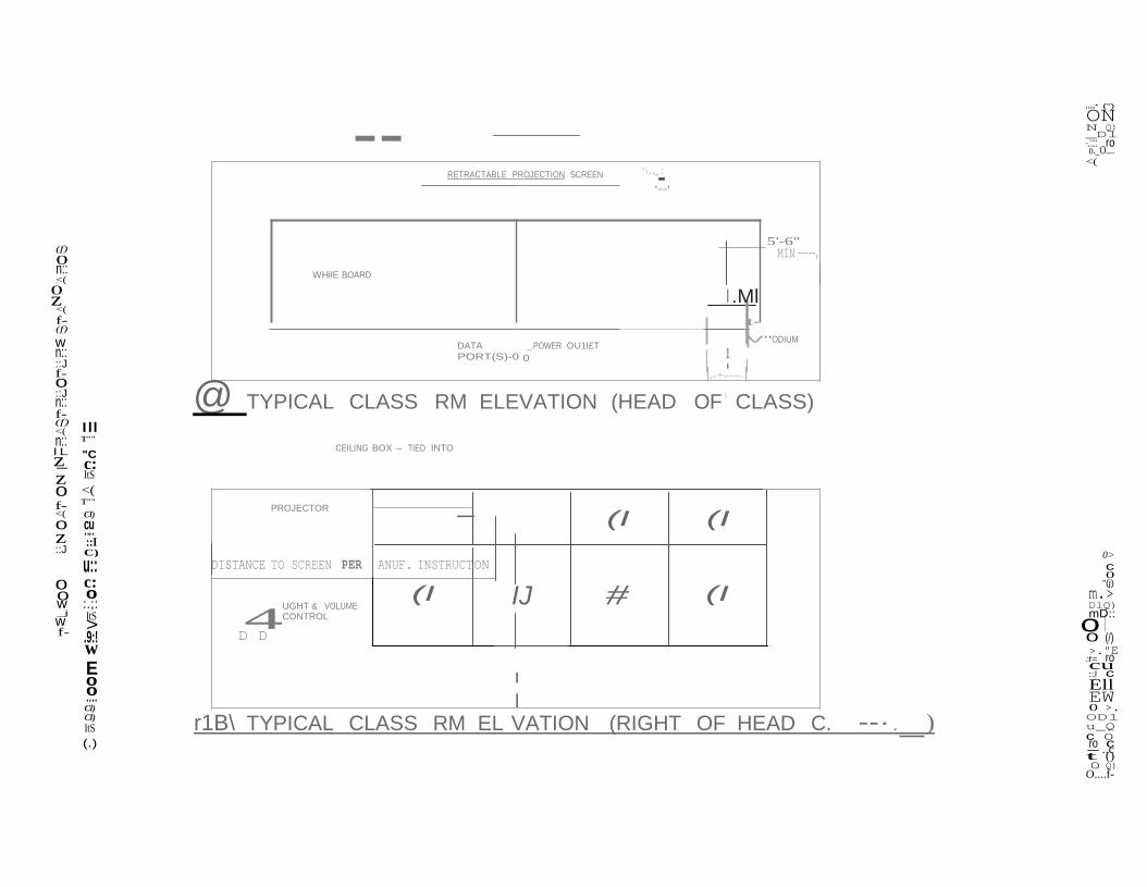
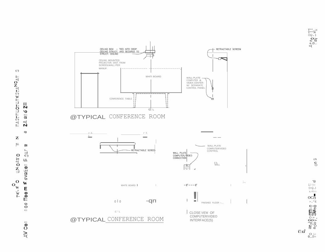
CLASSROOM MEDIA STANDARDS
A. Media Equipped Classroom
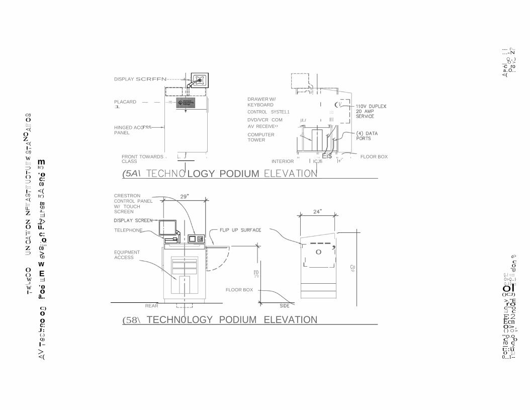
• In all classrooms the contractor will provide a floor box, conduit pathway, power, data and a ceiling box to support media presentation technologies. See Appendix D for Approved Product Manufacturers.
• An owner installed media equipped lectern will be placed over the floor box in the classroom. See Media Classroom Technology Figures 1-9 below.
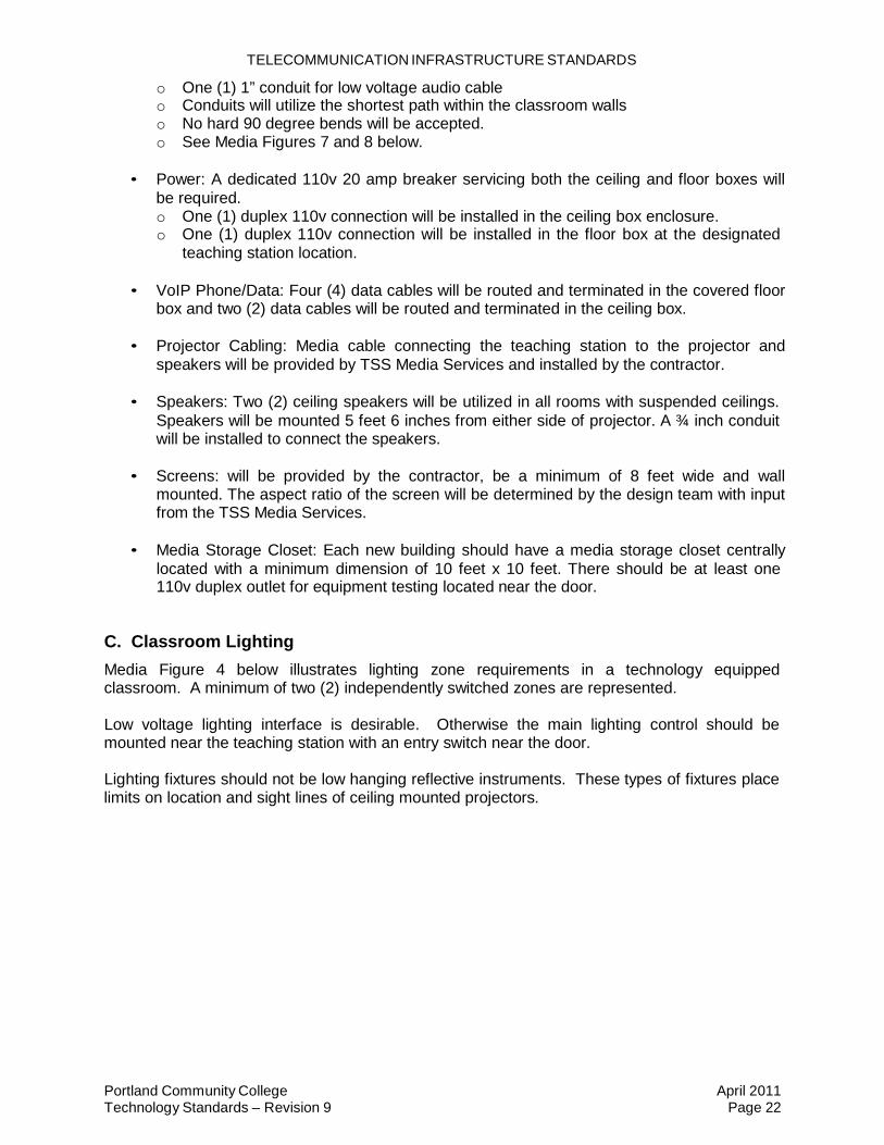
B. Pathway Standards
Minimum pathway and connectivity requirements for all classroom media construction are as follows. The media conduit pathways will be local to the classroom.
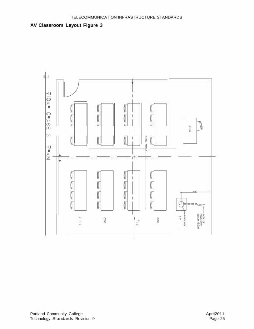
• Floor Box: One floor box will be installed in the front corner of the room beneath the
teaching station location. The placement will be a minimum of 5'-6" from each wall to allow for ADA requirements. See Appendix D for Approved Product Manufacturers.
• The floor box will require: o One (1) 1¼” conduit for low voltage video cable o One (1) 1” conduit for low voltage audio cable o One (1) ¾” conduit for dedicated 20 amp 110v electrical cable o One (1) 1” conduit for four (4) network data cables o See Media Figure 7 below
• Ceiling Box: One ceiling box will be installed in the ceiling grid at the projector location.
The ceiling box acts as a junction box for wiring for power, data, and media wiring in the ceiling. The architect must confirm the throw distance, aspect ratio, and location for the ceiling box being installed during the design phase for each building with TSS Media Services o The ceiling box will be mounted 14 feet from the center of an 8 or 9 foot screen. o The ceiling box will be centered with the screen. o See Media Figure 7 below. o See Appendix D for Approved Product Manufacturers.
• Connectivity between the Floor Box and the Ceiling Box will require two (2) conduits:
o One (1) 1¼” conduit for low voltage video cable
Portland Community College Technology Standards – Revision 9
April 2011 Page 22
TELECOMMUNICATION INFRASTRUCTURE STANDARDS
o One (1) 1” conduit for low voltage audio cable o Conduits will utilize the shortest path within the classroom walls o No hard 90 degree bends will be accepted. o See Media Figures 7 and 8 below.
• Power: A dedicated 110v 20 amp breaker servicing both the ceiling and floor boxes will
be required. o One (1) duplex 110v connection will be installed in the ceiling box enclosure. o One (1) duplex 110v connection will be installed in the floor box at the designated
teaching station location.
• VoIP Phone/Data: Four (4) data cables will be routed and terminated in the covered floor box and two (2) data cables will be routed and terminated in the ceiling box.
• Projector Cabling: Media cable connecting the teaching station to the projector and
speakers will be provided by TSS Media Services and installed by the contractor.
• Speakers: Two (2) ceiling speakers will be utilized in all rooms with suspended ceilings. Speakers will be mounted 5 feet 6 inches from either side of projector. A ¾ inch conduit will be installed to connect the speakers.
• Screens: will be provided by the contractor, be a minimum of 8 feet wide and wall
mounted. The aspect ratio of the screen will be determined by the design team with input from the TSS Media Services.
• Media Storage Closet: Each new building should have a media storage closet centrally
located with a minimum dimension of 10 feet x 10 feet. There should be at least one 110v duplex outlet for equipment testing located near the door.
C. Classroom Lighting
Media Figure 4 below illustrates lighting zone requirements in a technology equipped classroom. A minimum of two (2) independently switched zones are represented.
Low voltage lighting interface is desirable. Otherwise the main lighting control should be mounted near the teaching station with an entry switch near the door.
Lighting fixtures should not be low hanging reflective instruments. These types of fixtures place limits on location and sight lines of ceiling mounted projectors.
--
<(
z
w 4 o l
-- RETRACTABLE PROJECTION SCREEN "\.._ 1
'--'
.....- (")
ON N Q) _Dl ·.:::: ro o._O....
<(
(f) 0 n:: <( 0z <( f- (f)
WHilE BOARD
I .Ml
t-
5'-6" MIN -----,
w n:: ::J
DATA _.POWER OU1l£T PORT(S)-0 0
V"ODIUM
1 I
f- 0 ::J n:: f- (f) Ill
,-+----.,
@ TYPICAL CLASS RM ELEVATION (HEAD OF 1 CLASS)
n:: T"" CEILING BOX - TIED INTO
lzL "C - c: z ItS 0 <( f- T"" <( Cl) 0 c..u..
::I ::J C)
u:: 0 c:
PROJECTOR - DISTANCE TO SCREEN PER ANUF. INSTRUCTON
(I (I
0> c 0
"(j)
0 0 w :.;: _j ItS
> f- .9:! w E 0 0....
UGHT & VOLUME CONTROL
D D
(I IJ # (I
I I
m.> DlQ) mD::
0 (/) >."E
:t= ro cu ::J c Ell EW
Cl) Cl) ItS (.)
r1B\ TYPICAL CLASS RM EL VATION (RIGHT OF HEAD C. --· , ) 0 >. ODl u_Q c 0 ro c - ..c t () 0 Q)
O....f-
N I-
z
z >
E
E(f)
>
- I
I
<(
w w
T"""...;:t T"""N OQ.) 0>
·c ro o..O... <(
(/)
0::: <( 0z <( I- (/) w 0::: ::J Ill 0 ::J '0 0::: r:::::: I- cu (/)
CEILING MOUNTED PROJECTOR, DIST. FROM SCREEN WALL PER MANUF. -------------- -----------------,
WHITt BOARD WALL PLATE
COMPUTER & VIDEA CENTER W/ SEPARATE CONTROL PANEL
CONFERENCE TABLE
@TYPICAL CONFERENCE ROOM <( <( 0::: N
Q) r1 r1
z LL tn
s... :::l
0 C') i= L1. 0 r::::::
0 ::J :,i:i cu
Q)
I --
r 1 WALL PLATE COMPUTER/VIDEO CONTROL
(J)
FA c WALL I 0
0 ;., "(j) 0 WHITE BOARD I I -r---r I Q.) ·::;:
O>Q.) _J w 0 I- 0
0::: Q) 0 r::::::
o l o -qnr I !I
FINISHED FLOOR --.... I I
a.>O::: I
OCJ) >."E c-o :::J c
C ' L I CLOSE VIEW OF E$
r:::::: 0 ()
<(
@TYPICAL CONFERENCE ROOM COMPUTER/VIDEO INTERFACE(S)
0>. 00> ""O_Q c 0 ro c
-t::u..c 0 Q.) 0...1--
-
(f)
TELECOMMUNICATION INFRASTRUCTURE STANDARDS
AV Classroom Layout Figure 3
"p'TJt..l
-u 0 )> I
0 I )> (f)
c ITI Ul
:;o "
-u I )> z +
N
ITI
"'
Portland Community College Technology Standards- Revision 9
I z ITI
"'
April2011
Page 25

I I HUNG CEILING L t J
I
II
w ....,
e
w Q)
<( t i
ol
Cf) 0 0:::
0z
ZONE 1
I I I PATH OF
CONDUIT(S) ABOVE
11
I TECHNOLOGY
io PODIUM BELOW
,- l I MAIN LIGHT
CONTROL -- 5'-6"
...--(()
...-N Q.) _0> ·c ro a..O... <(
<( CLASS ROOM AREA UGH I " <( I- Cf)
w 0::: ::::> I- () ::::>
II ll II II
CLASS ROOM AREA LIGH I ZONE 2 II
II CEILING BOX IN DROP] II
CEILING, PROJECTOR BELOW 11
APPROX. 5'-6" IU APPROX. 5'-6"
--m-+§+::t:--J
0::: -.::1' I- Cf)
0::: :::l LL C) z i.L z c: 0 .!!! i= a.. <( () C)
z c: ::::> Q)
(..)
0 '0 () Q)
(.) _J
I- ;;:::
E 0 0 a.. tn
CL
ENTRY LIGHT- CONTROL
CEILIQ OUNTED SPEAKII:RS
CLASS ROOM AREA LIGHi
ZONE 1
CLASS ROOM AREA UGH I ZONE 2
a> c 0 "(j)
Q.) ·::;: O>Q.) Q.)0::: ()CJ) >."E ro
C"O :::J c E2 Ecn 0>.
tn .!!! (..)
f'4'\ TYPICAL CLASS RM REFLECTED CEILING PLAN \!V
()O> "O.Q c 0 ro c - ..c t::u 0 Q.) 0...1--
w
()
z 0u:.:.:
>
co
E
ol
>
DISPLAY SCRFFN------+-1
....... ('-...
...-N Q.) _0> ·c ro a..O... <(
Cf)
PLACARD - - ---Ht---1
DRAWER W/ KEYBOARD I (V CONTROL SYSTE1.1 1 11
0 DVD/VCR COM jlJL.f I Ill 0::: <( 0z <( I- Cf)
HINGED ACC PANEL
AV RECEIVE0 - u Tlr
COMPUTER -!!. TOWER
0::: m ::::> It')
FRONT TOWARDS I L.. J I II " I Ei$ II , I FLOOR BOX CLASS INTERIOR I ICJfi I+'
I- '0 ::::> c: 0::: I- <( Cf) It') <(
tn Q) a.. :::l
z .2> 0 u. i= c: <( 0 () :.;; z co ::::>
Q)
w
(5A\ CRESTRON CONTROL PANEL W/ TOUCH SCREEN TELEPHONE
EQUIPMENT ACCESS
LOGY PODIUM
---, 0 I a>
I I c
0 () w :::l _J
w '0 I- 0
a..
C) 0
REAR
FLOOR BOX
ro 1"0
L _j Co '<I-
0 "(j)
Q.) ·::;: O>Q.) Q.)0::: ()CJ) >."E ro
C""O :::J c
0 c: J: (.) Q) I-
<(
(58\ TECHN01 LOGY PODIUM ELEVATION E2 Ecn 0>. ()O> ""O.Q c 0 ro c - ..c t::u 0 Q.) 0...1--

L >
E
u.
w ol
c
>
DISPLAY SCREEN
....... 00
...-N OQ.) 0>
·c ro a..O... <(
Cf) 0 0::: <( 0z <( I- Cf)
w (.0 0::: Q)
REAR
DVD/VCR COM AV RECEIVER
I I --U---- COMPUTER 11---L-------11 TOWER
;---
FLOOR ::::> a.. I- :::l () C) ::::> 0::: I- c: Cf) 0 <( :.;; L0::: co z Q)
z w 0 i= <( :::l () '0 z 0 ::::> a..
Q)
-:.r ........... I"')
'<I- I "N
L---
BOX ./.
- 1 ' 10 I l /
- ------..-1
I"')
........, a> c
0 ...., () en _J
w tn
FRONT TOWARDS CLASS
HINGED ACCESS PANEL(S)
SIDE 0 "(j)
Q.) ·::;: O>Q.) Q.)0:::
I- Q)
C) 0 0 c: J: (.) Q) I-
<(
(6\ALTERNATE DESK STYLE PODIUM ()CJ) >."E ro
C"'O :::J c E2 Ecn 0>. ()O> "'O.Q c 0 ro c - ..c t::u 0 Q.) 0...1--

0 ·- E
LL
"C
c..
- >
ol
0
-
r- (]) ON N Q) _Dl ·.:::: ro o..O...
<(
(f) 0 n:: <( 0z <(
r-..
C..1>. f- ::::s (f) C) w n:: ::J f-
::::s ::J n:: 0 f- (f)
3/J,." CONDUIT - FOR POWER CONNECll\'llY - Win-liN WALL
._- - i-+ 1" CONDUIT- FOR
NETWORK DATA_. - _ WllHIN WALL
----== ---= =::;;;;;; ------==== ---= RETRACTABLE PROJEC ON SCREEN
_j__ ======== ===-----
<( >. n:: C) lzL 0
1" CONDUIT - FOR LOW VOLTAGE
0 z I:
CABUNG - WITHIN WALL
WHITE BOARD
0 .I: 1 1/J,." CONDUIT -
f- <( 0 z ::J
u C1> I- .I:
·
FOR AUDIOVISUAL CABUNC - WITHIN WALL
(])
c 0
0 C1> 0 w _j
E
·"TECHNOLOGY PODIU "(j) m.> DlQ) mD::
w f- 0...
Cl) Cl) ra (.)
C1> "C
3:
(7\ TYPICAL VIEW OF CLASS ROOM W/TECHNOLOGY PODIUM
0 (/) >."E
:t= ro cu ::J c Ell EW 0 >. ODl ""D_Q c 0 ro c - ..c t () 0 Q) O...f-

TELECOMMUNICATION INFRASTRUCTURE STANDARDS
-
!:
AV Classroom View with Technology Podium Figure 8
---j
-u< 0 )> r < 1'1
0 '1
0 I )> (}) (})
::;o 0 0
Ul
---j 1'1 r;:l 0 ::r:: z 0 r 0 G)
--< -o 0 0 c
liE ::til:(')
g riTJZO wo;:;j!;
0--j
56c:i! :!ioiz;co:: :i!Sllll :z,o
r-X
8 ::tl
Portland Community College Technology Standards- Revision 9
\ \
April 2011
Page 30

0(0
SCREEN W.A.LL PER
II
"' c:
0 QJ
w o l o
. o l
"C
0
CEILING BOX - nED INTO DROP CEILING STRUCT. ,l.ND SECURED TO STRUCT. CEILING --- -
RETR,l.CT,l.BLIE SCREEN
r- r- 0J Q) _Dl ·.:::: ro o..O...
<(
(f) 0 n:: <( 0z <(
CEILING MOUNTEID PRo.JECTOR, DIST. FROM
M.A.NUF. --------------+-----------+---,
WHITt BO.A.RD
I
f- (f) w n:: ::J f- 0 ::J Ill
..., r I I
CONFERENCE T,l.BLE I I II II II
C l L
l j-1 I I II II II II
FLOOR BOX
n:: 0') f-
VIDEO CONFERENCE ROOM (f) "C <( n:: lzL <(
0')
2'-10" WALL PLATE COf.lPUTER/VIDEO
z (I)
f- .... CONTROL
<( :::::J N
z u:: I ::J E
0 ALTERNATE "PROFESSION STYLE POOIU
COMPUTER DEO 0> CONNECnON
I c 0
0 0::: (j)
" . Q)·s;:
w QJ _j (J
c: f- Q...J. .!! c: 0 (.)
-} FLIP UP
.A.DDinON.A.L SURF.A.CE
C 1 L
WHITE BOAAD
-·---->1I<I-
I II
<D I -;....
II I I I
DlQ) mD::
0 (/) >.'E
:t= ro cu ::J c Ell
0 @ VIDEO CONFERENCE ROOM QJ
:; CLOL PODIUM
VIE
W OF
FLOOR BOX
EW 0 >. ODl u..Q c 0 ro c - ..c
() t 0 Q) O...f-

TELECOMMUNICATION INFRASTRUCTURE STANDARDS
Portland Community College Technology Standards – Revision 9
April 2011 Page 32
APPENDIX A – INSIDE CONDUIT AND PATHWAY REQUIREMENTS A. Conduit
The following types of conduit are approved for interior uses: • Rigid galvanized conduit, zinc coated and manufactured in accordance with UL-6, ANSI
and Federal Specification WW-C-540 standards • Intermediate Metal Conduit (IMC), zinc coated galvanized steel to comply with UL-1242,
Type J and ANSI Standards • Electrical Metallic Tubing (EMT), zinc-coated steel to comply with UL-797 and ANSI
Standards • Liquid tight flexible metal conduit, zinc steel core with smooth gray abrasion resistant,
liquid tight, polyvinyl chloride covering (with integral ground wire wound in steel core), to comply with UL360 and ANSI Standards. Anaconda Sealtite type U.A or similar
• Flexible metal conduit, to comply with UL360, ANSI Standards and Federal Specification WW-6-566
B. Wireways
The following are approved: • Non-exposed, all steel in construction with screw covers. All surfaces shall be coated
with a rust preventing coating with final finish being gray. • Surface raceway, may be steel or UL listed non-metallic product. Where power and
signal (low voltage) cables share a common pathway, an approved divider must be present. All fittings and transitions pieces are to be of the same manufacturer, however, power and low voltage receptacles may be from a different manufacturer so long as the product is designed to be an integral part of the completed system. In addition, where a metallic system is specified, the following requirements apply: o Material is to be grounded to known source of building ground o All cut edges that will be exposed to cable shall be finished with a grommet or
dielectric bushing material to protect cable from chaffing. o All visible cuts shall be painted to match overall color of product.
C. Pathway
• Pathway shall conform to the requirements of TIA 569-B specifically:
o The scope of this Standard is limited to the telecommunications aspect of commercial building design and construction, encompassing telecommunications considerations both within and between buildings.
o Telecommunications aspects are generally the pathways into which telecommunications media are placed and the rooms and areas associated with the building used to terminate media and install telecommunications equipment.
o The scope is limited only to the telecommunications aspect of building design, this Standard significantly influences the design of other building services, such as electrical power and HVAC. This Standard also impacts space allocation within the building.
TELECOMMUNICATION INFRASTRUCTURE STANDARDS
Portland Community College Technology Standards – Revision 9
April 2011 Page 33
APPENDIX B – OUTSIDE PLANT CONDUIT AND VAULT DETAIL
A. Outside Plant Conduit
All conduits installed “outside” are considered subsurface pathways. Approved conduit types are:
• EB-20 for encasement in concrete; • EB-35 for encasement in concrete; • DB-60 for direct burial or encasement in concrete; • DB-100 for direct burial or encasement in concrete; • DB-120 for direct burial or encasement in concrete; • Rigid Nonmetallic Conduit Schedule 40 for direct burial or encasement in concrete; • Rigid Nonmetallic Conduit Schedule 80 for direct burial or encasement in concrete; • Multiple Plastic Duct (MPD) for direct burial or installation in conduit; • Rigid Metallic Conduit for direct burial or encasement in concrete; • Intermediate Metallic Conduit for direct burial or encasement in concrete; • Fiberglass Duct for direct burial or encasement in concrete; • Innerduct Polyethylene (PE) for direct burial or installation in conduit; • Innerduct Polyvinyl Chloride (PVC) for direct burial or installation in conduit.
B. Installation
Installation shall conform to the following: • Encased buried (EB-20) and direct-buried (DB-60) conduit shall meet NEMA standard
TC-6. • Encased buried (EB-35) and direct-buried (DB-120) conduit shall meet NEMA standard
TC-8. • Schedule 40 and Schedule 80 Rigid Nonmetallic conduit shall meet NEMA standard
TC-2.
Nonmetallic conduits shall be encased in concrete of minimum 17,225 kPa (2500 lb/in 2) compressive strength where vehicular traffic (i.e., automotive, railway) is above the pathway, or where a bend or sweep is placed. All bends shall be sweeps with a minimum radius of six times the internal diameter (ID) for conduits up to 2 inch and ten times the ID for all conduits larger than 2 inch.
C. Design Elements
The following is a list of construction elements that need to be considered in the design and installation of subsurface pathways.
• Excavation; • Clearances and separations from other utilities; • Depth of burial; • Buried street crossings; • Casing; • Trenching; • Boring (pipe pushing); • Plowing; • Backfill; and, • Restore landscape.
TELECOMMUNICATION INFRASTRUCTURE STANDARDS
Portland Community College Technology Standards – Revision 9
April 2011 Page 34
D. Vaults
All vaults shall meet the following criteria; • Corrosion resistance of metal components. ASTM B 117 salt spray test for (30) days; • Chemical resistance of nonmetallic components (gasoline, kerosene, acid/base etc.)
ASTM D543; • UV degradation of nonmetallic components. ASTM G 53 for (90 days - UVB-313 lamps); • Resistance to flame or fire RUS Specification PE-35 or ASTM D 635.
E. Loading Requirements:
• Light duty (pedestrian traffic only), designed for protected areas only. (Test load 1361 kg [3000 lb] over 254 mm by 254 mm [10 in by 10 in] area with 13 mm [0.5 in] maximum deflection);
• H-5, designed for sidewalk applications and for occasional non-deliberate traffic (test load 5118 kg (11284 lb) over 254 mm by 254 mm [10 in by 10 in] area with 13 mm [0.5 in] maximum deflection);
• H-10, designed for driveways, parking lots and off road application subject to occasional non-deliberate heavy vehicles (test load 22,568 lbs. over 254 mm by 254 mm [10 in by 10 in] area with 13 mm [0.5 in] maximum deflection); and
• H-20, designed for deliberate heavy vehicular traffic.

TELECOMMUNICATION INFRASTRUCTURE STANDARDS
Portland Community College Technology Standards – Revision 9
April 2011 Page 35
APPENDIX C – OUTSIDE CONDUIT SYSTEM AND VAULT INSTALLATION
GUIDELINES
Outside plant conduit and vault systems installed at facilities require unique and careful planning prior to placement. In most installations, the conduit duct bank is designed to include electrical, security, pneumatic control systems, video distribution, and telecommunications. The duct bank typically runs parallel to or at right angles from the major structures. Duct banks may be encased at bends or for their entire runs in concrete. As such, it is imperative to allocate pathway for the immediate needs, but to include a one hundred percent growth factor for future systems that will be required over the life span of the institution.
A. Vault Placement and Security
Vaults are in almost all cases; shared among low voltage applications, i.e., telecommunications, alarm, security, video, HVAC control systems, etc. Sizing and placement of the vaults requires consideration of the likelihood of re-entry and the physical security required for protection against unauthorized access.
B. Drainage
Installation of vaults should be such that water drainage will continue after the installation. In some instances the soil grading will be sufficient, while in other instances gravel may have to be placed at specified depths. The vault may be located below grade, in which case locator stakes or location devices should be employed. The location of the vault should be away from traffic conditions that could cause injury to personnel, yet it should be easily accessible for maintenance.
C. Vault Racking and Space Allocations
Approved vaults range in size from 4’ x 4’ x 6’ up to 8’ x 8’.x 12’. Conduits enter and exit these vaults in a variety of sizes and configurations. Allocation of space needs to be coordinated with all systems that will transverse the vault.
• For telecommunications systems, the following guidelines apply: o Splicing of fiber and copper cabling is not allowed. o Fiber optic cable will be completely encased in innerduct. The innerduct will be
labeled as it passes through the vault. o Copper tie and supply cables passing though vaults and be likewise labeled.
D. Conduit Allocation and Fill Procedures.
• All conduits shall be numbered and documented on site plan as-built drawings. • All conduits that are not in use shall be plugged with a watertight duct plug designed
specifically for such purpose. Separate conduits shall be allocated for fiber and high pair count copper cables. In the case of four-inch conduits allocated for fiber, five (5) one- inch innerducts shall be installed as a part of the initial activation. One, or more, of the innerducts shall be used for the initial fiber allocation with the remaining being allocated as spares. Innerduct shall be labeled at each end and where is passed through a vault as “ccc - iii”, where ccc = the conduit number from the site as-built drawings and iii = the innerduct number, 1 – 5, within the conduit.

TELECOMMUNICATION INFRASTRUCTURE STANDARDS
Portland Community College Technology Standards – Revision 9
April 2011 Page 36
APPENDIX D – PRE-APPROVED PRODUCT SET
The following product sets meet or exceed the requirements set forth by Portland Community College:
Manufacturer Components
Panduit Category 6 product set including patch panels,
outlets, faceplates and patch cords Pre-connectorized fiber optic trunk assemblies Fiber optic cassettes used in conjunction with pre-connectorized trunk assemblies Fiber optic patch panels and connector used for field termination Fiber optic patch cord assemblies Surface mount raceway products
Chatsworth Products Incorporated (CPI) Cabinets, racks, vertical wire management,
overhead ladder tray (to be used in MDF/BDF and IDF locations as part of a seismic assembly) and all associated fastening hardware and components
APC Power distribution and surge suppression
Optical Cable Corporation (OCC) Fiber optic cable – Single mode outside plant
(OSP) fiber Cablofil Ladder tray and raceway products to be used
in areas other than MDF/BDF or IDF, i.e., hallways and corridors where support of large amounts of cable is required
Caddy Cable support devices
Wiremold
Cooper Notification
FSR Inc.Brand
AMAG Access Control System
Axis Video Surveillance system
Surface mounted metallic raceway SAFEPATH Mass Notification System (MNS) Floor box Ceiling box AMAG Enterprise Edition Axis Cameras
EZ-Path EZ Path® System Series 44+

TELECOMMUNICATION INFRASTRUCTURE STANDARDS
Portland Community College Technology Standards – Revision 9
April 2011 Page 37
A. Approved Part Numbers.
Note that all part numbers will not be appropriate nor approved for every project. Speciation writer must closely coordinate with Technical Services prior to receiving bids on a project-by-project basis to guarantee correct part numbers are used. Not also that part numbers change and the then current part numbers will be specified on a project-by-project basis to be included in the Bid Specification package.
Manufacturer Description Part Number
APC 1 to 2500 Watts
Smart-UPS XL3000VA RM 3U 120V
SUA3000RMXL3U
Batteries RBC 105 Electrical Requirements
20 amp circuit, NEMA L5-120P
APC 2500 to 4000 Watts
Smart UPS RT 5000VA RM SURTD5000RMXLP3U
Batteries RBC 44 Electrical Requirements
30 amp circuit, NEMA L14-30P
APC 4000 to 8000 Watts
Smart UPS RT 10KVA RM 20 w/ (2) 208V to 120V 2U Step-Down Transformer
SURT10KRMXL6U
Battery Pack SURT192RMXLBP3U Electrical Requirements 60 amp, hard wire 3 wire (2PH+G) APC 8000 to 9600 Watts
Symmetra LX 12KVA scalable to 16
SYA12K16RMP
Battery Pack SYARMXR3B3 Electrical Requirements 100 amp, hard wire 4 wire (2PH+N+G) Chatsworth Products Inc (CPI)
Rack, two post, 19” x 84” 55053-x03
Rack, four post, 19” x 39” x 84”(H)
15053-703
QuadraRack 4 Post frame 50120-703 ExpandaRack QuadraRack 50110-703 Vertical Wire Management,
84” x 10”, double sided 30163-703
Vertical Wire management, 84” x 6”, double sided
30162-703
Horizontal Wire Management
30139-719
Horizontal Wire Management, 2U
30130-719
Cable Runway, 12” 10250-712 Butt Splices 11299-712 90 Degree Junction 11298-701

TELECOMMUNICATION INFRASTRUCTURE STANDARDS
Portland Community College Technology Standards – Revision 9
April 2011 Page 38
Manufacturer Description Part Number Chatsworth Products Inc (CPI)
90 Degree Corners, 12” raceway
10822-709
Wall Angle Support Kit, 12” 11421-712 Triangular Support Bracket,
12” 11312-712
Grounding Strap, 1 each 40164-001 Grounding Strap, 25 each 40164-025 End Cap (for raceway) 10642-001 Telecommunications Main
Ground Busbar (TMGB) 40153-020
Telecommunications Ground Busbar (TGB)
13622-010
Panduit Faceplate (four port) CFP4IW Faceplate (six port) CFP6IW Wall Phone Plate KWP6PY Category 6, 8-pin modular
jack CJ688TGBL
Category 5e, patch panel, 48 port
DP485E88TGY
Patch panel frame, wedge, 28 port
CPPLA24WBLY
Patch panel frame, wedge, 48 port
CPPLA48WBLY
Fiber Trunk Assembly, Female MTP to Female MTP
FSPXnn55FxxxA Where nn= strand count, 12 or 24 Where xxx= length, in feet 100’ or greater
Fiber Interconnect Cable, Female MTP to Female MTP
FX12D-5MxxY Where xx= length, in meters, 1M or greater
Fiber Cassette Rack Enclosure
FCE1U
Fiber Cassette, 6 LC (12 strand), 50/125m, Laser Optimized
FCXO-12-10Y
Fiber Cassette, 12 LC (24 strand), 50/125m, Laser Optimized
FCXO-24-10Y
Patch Cord, Category 6 UTPSPxccc Where x=l ength, in feet ccc= color

TELECOMMUNICATION INFRASTRUCTURE STANDARDS
Portland Community College Technology Standards – Revision 9
April 2011 Page 39
Manufacturer Description Part Number Optical Cable Corporation (OCC)
Custom Outside Plant Fiber - Single mode/ OM4 Multimode 50/125 m Laser Optimized
SLX Singlemode Low water Peak ALE 550 meter 10 GbE
Custom Outside Plant Fiber - Single mode/ OM4 Multimode 50/125 m Laser Optimized
SLB Singlemode Bend Tolerant ABE 550 meter 10 GbE Bend Tolerant
General Cable Category 6, UTP, Plenum GenSpeed 6000
MileStone Control Software Protect Corporate
Axis Interior Camera AXIS-216FD
Exterior Camera AXIS-225FD NVR is to be Raid System
Server N+1 redundancy. 30 days event monitoring.
AMAG Access Control System Software AMAG Enterprise Edition
Intrusion Module AMAG Intrusion Management Web Access Software Module XML Open Integration Software Module Directory Sync Manager Software Module Building Control w/BACnet Gateway Software Module Access Control Panel AMAG Symmetry M2100 or
approved equivalent Card Readers HID Multi-class R40 Read
Only Gray 34 Bit Badge Printer / Encoder See PCC security for
approved product. Request to Exit DS161 PIR exit sensor, Black Door Contact Sentrol 1080 G or approved
equivalent Raucous Sounder Piezo Electric Sentrol AE912
or approve equivalent 4 door Controller AMAG M2100 4DCU option
Module Ethernet Module AMAG M2100NIC option
Module Intrusion System DMP-XR500N Motion Sensor Sentrol AP669 Keypad DMP 793 Battery 12 volt battery backup
7AMP/HR with vented enclosure

TELECOMMUNICATION INFRASTRUCTURE STANDARDS
Portland Community College Technology Standards- Revision 9
April 2011 Page 40
Manufacturer Description Part Number FSR Inc. Floor Box FL-G4
Ceiling Box CB-22SP EZ Path® System Cable - Wall Penetration Series 44+

TELECOMMUNICATION INFRASTRUCTURE STANDARDS
Portland Community College Technology Standards – Revision 9
April 2011 Page 41
TM
GB
APPENDIX E – MAIN DISTRIBUTION FRAME (TYPICAL)
Wall mounted ladder rack for riser
cable
Entrance Conduits
Service
Providers 20'-0"
3'-0" 3'-0"
30'-0"
4'-0"
120 Volt 20 AMP for Telco
use
Rack
5 Rack
6 Rack
7 Rack
8
4'-0"
Mounted at base of vertical wire managers or as directed
by Owner
Rack
1 Rack
2
Rack
3
6" VM
4'-0" 10 " VM 10 " VM
10 " VM 10 " VM 6" VM
120 Volt 20 AMP Typical outlet
3'-0"
¾” Fire Treated Plywood

TELECOMMUNICATION INFRASTRUCTURE STANDARDS
Portland Community College Technology Standards – Revision 9
March 2011 Page 42
TMG
B
APPENDIX F – BUILDING DISTRIBUTION FRAME (TYPICAL)
15'-0"
4" Entrance Conduits
Wall mounted ladder rack for
riser cable
Rack 1 ¾” fire treated
plywood 6" VM
Rack 2
5'-0" 4'-0"
10" VM
Rack 3
10" VM
20'-0" Rack 4
10" VM
Rack 5
6" VM
Mount at base of vertical wire
management or as directed by Owner
3'-0"

TELECOMMUNICATION INFRASTRUCTURE STANDARDS
Portland Community College Technology Standards – Revision 9
March 2011 Page 43
TGB
APPENDIX G – INTERMEDIATE DISTRIBUTION FRAME (TYPICAL)
10'-0"
4 " Entrance Conduits from
BDF
Wall mounted ladder rack for
riser cable
Rack 1
¾” fire treated plywood
6 " VM
5'-0" Rack 2 4'-0"
10 " VM
Rack 3
15'-0"
10 " VM
Rack 4
6 " VM
Mount at base of vertical wire
management or as directed by Owner
3' min
3'-0"

TELECOMMUNICATION INFRASTRUCTURE STANDARDS
Portland Community College Technology Standards- Revision 9
March 2011 Page 44
APPENDIX H- MDF/BDF BAYFACE (TYPICAL)
BDF/MDF Bay Face (Typical) Build out shows max imum configuration, i.e ,
12 Panduit wedge panels populated with 48 Category 6 jacks for a total of 576 station ports
10 inch vertica l wire management
Maximum Ethernet switches, i.e., 12, 48 port
12Kva UPS to support VoiP and additional ancillary equipment that may be located in this room.
Actual bid specifications may call for different configuration to meet specific building requirements

TELECOMMUNICATION INFRASTRUCTURE STANDARDS
Portland Community College Technology Standards- Revision 9
March 2011 Page 45
APPENDIX I- IDF BAYFACE (TYPICAL)
Ftber Tte to BDF/MU'
Copper Tt e to BDF/ MIT
... !'. ... !'.
...
IDF Bay Face (Typical) Build out shows maximum configuration, i.e., 12 Panduit wedge panels populated with 48 Category 6 jacks for a total of 576 station ports. 10 inch vertical wire management Maximum Ethernet switches, i.e., 12, 48 port 5Kva UPS Actual bid specifications may call for different configuration to meet specific building requirements
0 0 0
0 0 Q 0

TELECOMMUNICATION INFRASTRUCTURE STANDARDS
APPENDIX J – BONDING AND GROUNDING DETAIL
A. Bonding
Electrical Entrance Facility MDF/BDF/IDF
N
TMGB or TGB
G
Grounding Electrode Conductor
Bonding conductor for Telecommunications as per table
Grounding Electrode System
Sizing of the Bonding Conductor Length (in feet) Size (AWG) Less than 13 6 14 – 20 4 21 – 26 3 27 – 33 2 34 – 41 1 42 – 52 1/0 53 – 66 2/0 Greater than 66 3/0
Table 2 – Bonding Conductor Sizing Portland Community College March 2011 Technology Standards – Revision 9 Page 46

TELECOMMUNICATION INFRASTRUCTURE STANDARDS
Portland Community College Technology Standards – Revision 9
March 2011 Page 47
B. Grounding
This section describes the characteristics of the major components of the telecommunications grounding and bonding infrastructure.
All grounding and bonding connectors shall be listed by a nationally recognized testing laboratory (“NRTL”) as required by the NEC. Note: Connectors are listed for the application (e.g., above ground or direct buried.)
All grounding and bonding conductors shall be copper and may be insulated. When conductors are insulated, they shall be listed for the application. The minimum bonding conductor size shall be a No. 6 THHN AWG. Note: Conductors are listed for the space in which they are intended to be placed, such as riser systems or plenum spaces.
Grounding and bonding conductors should not be placed in ferrous metallic conduit. If it is necessary to place grounding and bonding conductors in ferrous metallic conduit that exceeds 3 feet in length, the conductors shall be bonded to each end of the conduit using a grounding bushing or a No. 6 THHN AWG conductor, minimum.
C. Labeling, Color-Coding, and Marking
Each telecommunications grounding and bonding conductor shall be labeled. Labels shall be located on conductors as close as practicable to their point of termination in a readable position.
Labels shall be nonmetallic and include the information depicted in figure 4. Refer to ANSI/TIA/EIA 606-A for additional labeling requirements.
IF THIS CONNECTOR OR CABLE IS LOOSE OR MUST BE REMOVED PLEASE CALL TECHNOLOGY SERVICES MANAGER
Figure 4: Label for Grounding and Bonding Conductors
The Bonding Conductor for Telecommunications, each telecommunications bonding backbone (TBB) conductor, and each grounding equalizer (GE), shall be green or marked with a distinctive green color.
D. Telecommunications Main Grounding Busbar (TMGB)
The telecommunications main grounding buss bar (TMGB) serves as a dedicated extension of the building grounding electrode system and is exclusive for the telecommunications infrastructure.
The TMGB serves as the central attachment point for the telecommunications bonding backbone(s) (TBB) and equipment. Typically, there should be a single TMGB per building. Note: For buildings with more than one electrical service entrance, each of which serves telecommunications equipment, the contractor is urged to consult with a licensed engineer.
The ideal location of the TMGB is in the telecommunications entrance facility. However, the TMGB should be located to minimize the length of the bonding conductor for telecommunications system.
TELECOMMUNICATION INFRASTRUCTURE STANDARDS
Portland Community College Technology Standards – Revision 9
March 2011 Page 48
The TMGB should serve telecommunications equipment that is located within the same room or space. Extensions of the TMGB (i.e., other telecommunications buss bars in other telecommunications spaces) shall be TGBs.
The TMGB shall: • Be a predrilled copper buss bar provided with holes for use with standard sized lugs; • Be sized in accordance with the immediate application requirements and with
consideration of future growth; • Have minimum dimensions of ¼ inch thick x 4 inches wide and variable in length; • Be listed by a NRTL.
It is desirable that the buss bar be electro-tin plated for reduced contact resistance. If not plated, the buss bar shall be cleaned prior to fastening of conductors and an anti-oxidant should be applied to the contact area to control corrosion and reduce contact resistance.
E. Bonding to a Panel Board
Where a panel board (electrical power panel) is located in the same room or space as the TMGB that panel board’s alternating current equipment ground (“ACEG”) bus (when equipped) or the panel board enclosure shall be bonded to the TMGB.
The TMGB shall be as close to the panel board as practicable and shall be installed to maintain clearances required by applicable electrical codes.
F. Connections to the Telecommunications Main Grounding Busbar
The connections of the bonding conductor for telecommunications and the TBB to the TMGB shall utilize exothermic welding, listed compression two-hole lugs, suitable and equivalent one hole non-twisting lugs, or other irreversible compression type connections. Two-hole lugs are preferred.
The connection of conductors for bonding telecommunications equipment to the TMGB shall utilize exothermic welding, listed compression lugs, or other irreversible compression type connections. Two-hole lugs are preferred.
All metallic raceways for telecommunications cabling located within the same room or space as the TMGB shall be bonded to the TMGB. However for metallic pathways containing grounding conductors where the pathway is bonded to the grounding conductor, no additional bond to the TMGB is required.
G. Installation Requirements
The TMGB shall be insulated from its support. A minimum of 2” separation from the wall is recommended to allow access to the rear of the buss bar.
The TMGB shall be located such that it is accessible to telecommunications personnel. A practical location for the TMGB is to the side of the panel board (where provided). The mounting height of the TMGB should be adjusted to accommodate overhead or under floor cable routing.
H. Bonding Conductor for Telecommunications
The bonding conductor for telecommunications shall bond the TMGB to the service equipment (power) ground and be sized as per Table 2 above. The bonding conductor for telecommunications shall be, as a minimum, the same size as the TBB.
TELECOMMUNICATION INFRASTRUCTURE STANDARDS
Portland Community College Technology Standards – Revision 9
March 2011 Page 49
I. Telecommunications Bonding Backbone (“TBB”)
The TBB is a conductor that interconnects all TGBs with the TMGB. The TBB originates at the TMGB extends throughout the building using the telecommunications backbone pathways, and connects to the TGBs in all Telecom Rooms and Telco Entrance Rooms. The GE interconnects multiple TBBs.
The TBB should be designed with consideration given to the type of building construction, building size, general telecommunications requirements, and configuration of the telecommunications pathways and spaces. Specifically, the design of a TBB shall:
• Be consistent with the design of the telecommunications backbone cabling system; • Permit multiple TBBs as dictated by the building size; • Address routing to minimize the lengths of the TBBs. • The interior water piping system of the building shall not be used as a TBB. • The metallic cable shield shall not be used as a TBB.
Whenever two or more TBBs are used within a multistory building, the TBBs shall be bonded together with a GE (formerly known as telecommunications bonding backbone interconnecting bonding conductor) at the top floor and at a minimum of every third floor in between. The GE shall be sized as specified in Table 2.
J. Bonding and Sizing the TBB
The TBB shall be a copper conductor. The minimum TBB conductor size shall be a No. 6 AWG. The TBB should be sized at 2 kcmil per linear foot of conductor length up to a maximum size of 3/0 AWG (See Table 2 above). The TBB may be insulated. If the TBB is insulated, the insulation shall meet the fire ratings of its pathway. The sizing of the TBB is not intended to account for the reduction or control of electromagnetic interference.
The TBB shall be connected to the TMGB. The intended function of a TBB is to reduce or equalize potential differences between telecommunications systems. While the TBB will carry some current under ac power ground fault conditions, it is not intended to provide the only ground fault return path. A TBB is not intended to serve as the only conductor providing a ground fault current return path.
The TBB conductors shall be installed and protected from physical and mechanical damage.
The TBB conductors should be installed without splices. Where splices are necessary, the number of splices should be a minimum and they shall be accessible and located in telecommunications spaces. Joined segments of a TBB shall be connected using exothermic welding, irreversible compression-type connectors, or equivalent. All joints shall be adequately supported and protected from damage.
K. Telecommunications Grounding Busbar
The TGB is the grounding connection point for telecommunications systems and equipment in the area served by that telecommunications room or Telecommunications Room. (“TGB”) Description of the telecommunications grounding buss bar:
• Be a predrilled copper buss bar provided with holes for use with standard sized lugs. • Have minimum dimensions of ¼ inch thick x 2 inches wide and variable length of 12" to
20" to meet the application requirements and with consideration of future growth. • Must be listed by a nationally recognized testing laboratory.

TELECOMMUNICATION INFRASTRUCTURE STANDARDS
Portland Community College Technology Standards – Revision 9
March 2011 Page 50
It is desirable that the TGB be electro-tin-plated for reduced contact resistance. If not plated, the buss bar shall be cleaned prior to fastening the conductors to the buss bar, and an anti-oxidant should be applied to the contact area to control corrosion and reduce contact resistance.
L. Bonding to the TGB
The TBB and all TGBs within the same space shall be bonded to each other with a conductor the same size as the TBB.
The bonding conductor between a TBB and a TGB shall be continuous and routed in the shortest possible straight-line path.
Where a panel board (electrical power panel) for telecommunications equipment is located within the same room or space as the TGB, that panel board’s ACEG bus (when equipped) or the panel board enclosure shall be bonded to the TGB.
The TGB shall be as close to the panel board as is practicable and shall be installed to maintain clearances required by applicable electrical codes.
Where a panel board for telecommunications equipment is not located within the same room or space as the TGB, consideration should be given to bonding the panel board’s ACEG bus (when equipped) or the enclosure to the TGB.
The TGB shall be bonded to the GE where required.
All metallic raceways for telecommunications cabling located within the same room or space as the TGB shall be bonded to the TGB.
Connections to the telecommunications grounding buss bar (TGB)
Connections of the TBB and the GE to the TGB shall utilize exothermic weld connections, listed compression two hole lugs connectors, suitable and equivalent one-hole non-twisting lugs or other irreversible compression type connectors. Two-hole connectors are preferred.
The TGB shall be insulated from its support. A minimum of 2” separation from the wall is recommended to allow access to the rear of the buss bar.
A practical location for the TGB is to the side of the panel board (where provided). The vertical location of the TGB should take into consideration whether the bonding conductors are routed in an access floor or overhead cable tray.
M. Bonding to the Metal Building Frame
All connectors used for bonding to the metal frame of a building shall be listed for the intended purpose.
In a metal frame (structural steel) building, where the steel framework is readily accessible within the room; each TGB and TMGB shall be bonded to the vertical steel metal frame using a minimum No. 6 THHN AWG conductor.
Where the metal frame is external to the room and readily accessible, the metal frame should be bonded to the TGB or TMGB with a minimum No. 6 THHN AWG conductor.
When practicable because of shorter distances and, where horizontal steel members are permanently electrically bonded to vertical column members, the TGB may be bonded to these horizontal members in lieu of the vertical column members.
Current Standard (ANSI-J-STD-607-A-2002) does not require bonding of the steel bars of a reinforced concrete building to the TGB or TBB.

TELECOMMUNICATION INFRASTRUCTURE STANDARDS
APPENDIX K - GLOSSARY
Aerial Cable - Telecommunications cable installed on supporting structures such as poles, bridge hangers, building extension supports, etc. These cables are typically non-filled cables intended exclusively for aerial placement via a separate metallic “strand” cable, or with support strand embedded in the same outer sheath (figure 8 cable). Aerial Distribution Method - The method of running cable between buildings in campus systems by going through the air; that is, building to pole, pole to pole, and/or building to AIA - American Institute of Architects Air Handling Plenum - A designated area, closed or open, used for environmental air circulation (return air). American National Standards Institute (ANSI) - Organization responsible for the definition and maintenance of standards. ANSI is the principal group in the United States for defining relative standards. ANSI represents the United States in the International Standards Organization (ISO). Amplifier - An electronic component used to increase the strength of a transmitted analog signal. Performance is measured in decibels (dB). Application Layer - Layer 7 of the open system interconnect (OSI) model for data communications. It defines protocols for users or application programs. APPN Advanced peer-to-peer networking is a network architecture that allows mainframes, minicomputers and PCs to communicate as peers across LANs and WANs Approved Ground - Only as specified in NEC (National Electrical Code Handbook). Refer to articles 250-24, 250-50, 250-71, 250-80, 250-81, and 800-33 - 800-40 for compliant approved grounding methods and procedures. Refer to ANSI- J-STD-607-A-2002 for standard telecommunications grounding. Architecture - The manner in which a system (infrastructure, hardware and software) is designed. Architecture usually describes how the system is constructed, how the components fit together, and the protocols and interfaces used to integrate these components. It also defines the functions and description of data formats and procedures used for communication between nodes and workstations. Armor - An additional protective element beneath outer jacket to provide protection against severe outdoor environments. Usually made of plastic- coated steel, it may be corrugated for flexibility. Array Connector - A connector that aligns and protects fibers from a ribbon fiber optic cable. A fan out array design can be used to connect ribbon fiber optic cables to non-ribbon cables.
Attachments - A general term to include straps, bolts, clamps or brackets used to support cable in an aerial distribution scheme. Attenuation - The decrease in magnitude of power of a signal in transmission between points. For example, in fiber, expresses the total loss of an fiber optic consisting of the ratio of light output to light input. Attenuation is measured in decibels (fiber or copper) per kilometer (dB/km) at a specific wavelength or frequency. The lower the number, the better the overall performance. Typical multimode wavelengths are 850 - 1300 nanometers (nm) and single mode wavelengths are 1300 - 1550 nm. Copper is now characterized up to 350 MHz plus. AWG - American Wire Gauge Backboard - A rigid support for mounting telecommunications terminating hardware, blocks, cross-connect components and wiring. May also be used to attach and support entrance and distribution cables, splice cases, etc. Typically ¾ “ plywood anchored/fastened to existing wall. Backbone Cable - Typically considered to be horizontal or vertical distribution cable. Connects entrance facility to various floors or telecommunications closets. Some versions are shielded. Should be placed near central axis of building for protection and minimized risk of lightning strikes. Bend Radius - Measure for copper cable or fiber optic bends.. Typically 4X, 6X or 10X the outside diameter dependent on specific performance characteristic limitations. BICSI - Building Industry Consulting Services International Binder (cable) - A tape, film or thread used for holding assembled cable conductors in place. Bonding - A low-resistance path obtained by joining all current-carrying metallic elements to assure electrical continuity, and having the capacity to safely conduct any current introduced into the path. Breakout Cables - Multi-fiber compositions where each fiber is further protected by an additional jacket and optional strength elements. Buffer Tubes - Extruded cylindrical tubes covering fiber optic(s) used for protection and isolation. Building Core - That portion of any building devoted to stairwells, elevators, rest rooms, utility, mechanical, electrical, HVAC and telecommunications cabling/equipment. Building Entrance Area - The area inside a building where cables enter and may be connected to riser/backbone cables and where electrical protection is provided. The network interface, protectors and other distribution components for

TELECOMMUNICATION INFRASTRUCTURE STANDARDS
campus backbone subsystems, may also be located here. See Entrance Facility Building Distribution Frame (BDF) - The BDF serves at the point of entry for intra-building cables. The BDF will have inter-building connections of fiber, copper, and potentially coax cable between itself and all IDF(s) in a building. In general, a BDF will serve as an IDF for all voice, data, and video connections with-in 90 meters of the BDF. The BDF houses the network and video equipment used to support voice, data and video in the building. Bundle - Many individual fibers contained within a single jacket or buffer tube. Also, a group of buffered fibers distinguished in some fashion from another group in the same cable core. Buried Cable - A gel-filled, cable that is direct buried in a trench in such a fashion that it cannot be removed without excavation (FED-std-1037A). As a general reference to types, characteristics and makeup. Not to be confused with underground cable (in ducts). Cabinet - An enclosure that may house connection devices, terminated cables, splices, apparatus, wiring and equipment. Typically affords security and/or protection from prevailing conditions such as weather, vandalism or accidental damage. Cable Attenuation - The measure of the loss in electrical strength encountered by signals sent through cable. Cable Bend Radius - Cable bend radius during installation infers that the cable is experiencing a tensile load. Free bend infers a small allowable bend radius since it is at a condition of no load. Cable Listings - National Electrical Code (NEC)
Article 800: MPP Multipurpose Plenum MPR Multipurpose Riser CMP Plenum Rated Communications Cable CMR Riser Rated Communications Cable CM General Purpose Not Used In Plenums or Risers CMX Residential And Restricted Commercial Use Article 700: OFC Fiber optic, Conductive OFCP Fiber optic, Conductive, Plenum OFCR Fiber optic, Conductive, Riser OFN Fiber optic, Non-Conductive OFNP Fiber optic, Non- Conductive, Plenum OFNR Fiber optic, Non-Conductive, Riser
Refer to appropriate articles of the NEC handbook for details on ratings and specific approved applications. Cable Plant - The cable plant consists of all the optical elements, for example, fiber, connectors, splices, etc. between a transmitter and a receiver.
Campus - The buildings and contiguous property of a complex, such as a university, college, industrial park, military establishment, municipality or health care facility. Campus Backbone Cable - The communications cable that runs between buildings. Typical methods of installing campus backbone cable: in-conduit, direct buried, aerial, and in-tunnel (in steam tunnels). Campus Cable Entrance - The point at which campus backbone system cabling (aerial, direct- buried, or underground) enters a building. Category 1-6a Cabling - (Structured Wiring)
Cat 1 POTS Voice And Low-Speed Data Cat 2 ISDN, Low-Speed Data, Cat 3 Cables/connecting hardware with transmission characteristics up to 16 MHz Cat 4 Cables/connecting hardware with transmission characteristics up to 20 MHz Cat 5 Cables/connecting hardware with transmission characteristics up to 100 MHz Cat 5e Cables/connecting hardware with transmission characteristics up to 155 MHz Cat 6 Cables/connecting hardware with transmission characteristics up to 250MHz Cat 6a Cables/connecting hardware with transmission characteristics up to 500MHz
Ceiling Distribution Systems - Distribution systems that use the space between a suspended or false ceiling and the structural floor of the story above for placing the cable. Methods include zone, poke-through, conduit, raceway and cable trays. Centralized Cabling - A cabling topology used with centralized electronics connecting the horizontal cabling with intra-building backbone cabling in the telecommunications room. Central Member - The center component of a cable. It serves as an anti-buckling element to resist temperature-induced stresses. Sometimes serves as a strength element. The central member material is steel, fiberglass, or glass-reinforced plastic. Central Office - Facility where common carriers originate subscriber’s circuits and where the switching equipment that interconnects those circuits is located. Cladding - The low refractive index material that surrounds the core of an fiber optic, usually silica. Client - A node that requests network services from a server. Coating - A protective layer of material over the cladding of a fiber optic. Coaxial Cable - A cable with one transmission conductor (inner conductor) and an outer conductor/braid/shield insulated from one another by dielectric foam. Collapsed Backbone - A local area network configuration wherein bridging and routing functions

TELECOMMUNICATION INFRASTRUCTURE STANDARDS
are located at the main cross-connect and accessed via concentrators at the horizontal cross-connects. Communication Power Pole - A raceway placed between the ceiling and floor used in conjunction with a ceiling distribution system for the purpose of distributing communication and power service to a work area. Also called utility column, ceiling drop pole, tele-power pole, or power pole. Composite Cable - A cable construction technique that combines multiple cables or media in a single over jacket. Conductor - A medium such as copper wire that can carry electrical current. Conduit - A pipe, usually metal, that runs underground, from floor to floor, or along a floor or ceiling to protect cables. In the riser backbone subsystem when riser telecommunications closets are not aligned, conduit is used to protect cable and to provide the means for pulling cable from floor to floor. In the horizontal subsystem, conduit may be used between a telecommunications closet and an information outlet in an office or other room. Conduit is also used for campus distribution, where it is run between buildings and intermediate manholes and is made of PVC occasionally encased in concrete. Conduit Sizing - All (intra and inter-building network cabling) conduits should be sized at a minimum of 4 inches. When placing new conduits, size installation to include one spare 4" conduit for future. All cores and sleeves should meet same criteria (min. 4 in.). Connecting Hardware - A device used to terminate cable with connectors and adapters that provide an administration point for cross connecting between cabling segments or interconnecting to electronic equipment. Cord - A flexible insulated cable (stranded vs. solid conductors). Core - (a) The central transmission area of a fiber. The core always has a refractive index higher than that of the cladding or (b) section of building dedicated to utilities, HVAC, mechanical, electrical, etc. See building core. Cross-Connect - System component where communication circuits are administered (that is, added or rearranged using jumper wire or patch cords). In 110 connector systems, jumper wire or patch cords are used to make circuit connections. In fiber optic connector systems, fiber optic patch cords are used. The cross-connect is located in a Telecommunications Room Cross-Connect Field - Copper wire or fiber terminations grouped to provide cross-connect capability. The groups are identified by color-coded sections of backboards mounted on the wall in Telecommunications Room or telecommunications closets, or by designation strips or labels placed on
the wiring block or unit. The color-coding identifies the type of circuit that terminates at the field. See TIA/EIA 606. Crosstalk - Undesired signals in one circuit as a result of inductive coupling from another circuit. See Near End Crosstalk (NEXT). Daisy Chain - A cabling practice no longer recommended, where devices were connected from one to another in a chain configuration. Data Link Layer - Layer 2 of the open system interconnect (OSI) model; it defines protocols governing data packetizing and transmission into and out of each node. Decibel (dB) - The standard unit for expressing transmission gain or loss and relative power ratios. The decibel is one-tenth the size of a Bel, which is too large a unit for convenient use. Both units are expressed in terms of logarithm to the base 10 of a power ratio used primarily for attenuation and crosstalk measurements in telecommunications. Decibel/kilometer (dB/km) - A unit of measurement for fiber optic attenuation. DEMARC - Demarcation point is the point of interface that readily identifies division of loop or circuit responsibility. Other terms frequently applied (properly or improperly): SNI (subscriber network interface), MPOE (minimum point of entry), EF (entrance facility) and others. Dielectric - A non-conducting or insulating material that prevents passage of electric current and resists inductive coupling. Distributed Architecture - A network that uses a shared communications medium (such as star, bus or ring LAN) and uses shared access methods. Distribution Block/Frame - Centralized connection equipment where telephone or data terminal cabling is terminated and cross-connections are made. Distribution Field - The cross-connect or interconnect field used to further distribute the cabling from one point in the network to another. Distribution fields are color coded by function (TIA- 569-B). Duplex - (a) In data communications, a circuit used to transmit/receive signals simultaneously in both directions, or (b) in general, two receptacles or jacks in a common housing which accepts two plugs. Electromagnetic - Referring to the combined electric and magnetic fields caused by electron motion through conductors. Electromagnetic Interference (EMI) - The interference in signal transmission or reception caused by the radiation of electrical and magnetic fields. See RFI, Radio Frequency Interference. Electronic Industries Alliance (EIA) - Governing agency for established standards and published test procedures.

TELECOMMUNICATION INFRASTRUCTURE STANDARDS
Emergency Power - An alternate electrical supply source, separate and distinct from the primary electrical utility (generators, batteries, etc.). Typically referred to as "back up", "hot standby", standby, emergency generators, etc. Entrance Facility - Typically denotes any or all of the following: telecommunications space, equipment, support hardware, cables, connectors, blocks, protectors, sleeves, splices, or other items specific to the DEMARC or MPOE where telco responsibility ends and the customer’s begins. Also known as: telecommunications service entrance or EF. Equipment Subsystem - The part of a premises distribution system that includes the cable and distribution components in an Telecommunications Room and that interconnects system-common equipment, other associated equipment, and cross- connects. Ferrule - A mechanical fixture, typically a rigid tube, used to protect and align a fiber in a connector. Generally associated with fiber optic connectors. Fiber - Thin filament of glass. An optical wave guide consisting of a core and a cladding that is capable of carrying information in the form of light. Fiber Optic Cable - A transmission medium consisting of a core of glass or plastic surrounded by a protective cladding, strengthening material, and outer jacket. Signals are transmitted as light pulses, introduced into the fiber by a light transmitter. Some of the advantages offered by fiber optic cable are low data loss, high-speed transmission, greater bandwidth, small physical size, lightweight, and freedom from electromagnetic interference or electrical ground problems. Common types are single, dual, multi-fiber and ribbon. Fiber Optic Connectors - Connectors designed to connect and disconnect either single or multiple fiber optics repeatedly. Fiber optic connectors are used to connect fiber cable to equipment and interconnect cables. Fiber Optic Cross-Connection - Fiber optic apparatus for terminating cable in couplings. Designed for high-density cross-connection fields, the apparatus can terminate up to 72 fibers on each shelf, with up to nine shelves in a bay frame. Single shelves can also be wall mounted. Cross connections are handled with fiber optic patch cords. Fiber Optics - The technique of conveying light or images through glass or plastic fibers. Coherent fiber optics should actually be called aligned fiber optics because the fibers are all the same length and are held in a constant spatial relationship. Fire Wall - A wall that helps prevent fire spreading from one contained area to another and that runs from structural floor to structural ceiling.
Firestop, Firestopping - (a) A material, device, or assembly of parts installed after penetration of a fire- rated wall, ceiling or floor area to prevent passage of flame, smoke or gases through the rated barrier. Refer to NFPA specifications for the intended application(s). - (b) The use of special devices and materials to prevent the outbreak of fire within telecommunications utility spaces and to block the spread of fire, smoke, toxic gases and fluids through openings, cable apertures and along cable pathways. The techniques used are often mandated by local building codes. Note: Classifications are available under the rating criteria of ASTM E814. Rating/Achievement:
F - Withstands the fire test for the rating period without: Permitting flames to pass through the fire stop flame occurring on any element of the unexposed side of the fire stop (auto-ignition) developing any opening in the fire stop that permits a projection of water beyond the unexposed side during the hose strength test. T - Meets the criteria of an "F" rating and prevents the transmission of heat during the rating period so that the temperature rise is not more than 325 degrees Fahrenheit on any exposed surface, thermocouple or penetrating item.
Floor Box - A cast iron, stamped steel or nonmetallic box placed in the concrete floor (prior to pouring the concrete slab) of a building, which is fed via conduit and used to house voice, data, power or video connections. Frame - A metallic structure for supporting connectors, protectors, patch panels, blocks, etc. Gas Tube Protector - An over voltage protector featuring metallic electrodes which discharge in a gas atmosphere within a ceramic, glass or synthesized envelope. Gauge - A measure of a conducting wire’s physical size, usually referred to as AWG. See also American Wire Gauge (AWG). Gigahertz (GHz) - A unit of frequency equal to 1 billion Hertz. GND or GRD - Abbreviation for ground. Ground - An electrical connection to the earth, generally through a bonding conductor or ground grid. Also a common return to a point of zero potential, such as the main grounding buss bar. See ANSI-J-STD-607-A-2002. Grounding - A conducting connection, whether intentional or accidental, between an electrical circuit or equipment and the earth, or to some conducting body that serves in place of the earth. Grounding Conductor - The conductor used to connect electrical equipment to a grounding electrode. Also, bonding conductor.

TELECOMMUNICATION INFRASTRUCTURE STANDARDS
Grounding Electrode - A conductor or group of conductors (usually a rod, or grid) in direct contact with the earth, providing a connection to the earth. Ground Potential - The potential of the earth. A circuit, terminal, or chassis is said to be at ground potential when it is used as a reference point for other potentials in the system. Home-Run Method - A distribution method in which individual cables are run directly from the telecommunications closet to each information outlet in a star configuration. Horizontal Cabling - The portion of the cabling system extending from the work area outlet to the TC. The cross-connect facilities in the telecommunications closet are considered part of the horizontal cabling. Hybrid Cable - A cable containing two or more different types of cable, such as copper and fiber optic. ICEA - Insulated Cable Engineers Association Information Outlet (IO) also known as: Work Area Outlet (WA or TO) - A connecting device designed for a fixed location (usually a wall or floor in an office) on which horizontal cable pairs terminate and which receives an inserted plug. It is the point where the horizontal system meets the work area. Although such devices are also referred to as phone jacks, the term information outlet or WA or TO encompasses the integration of voice, data and other communication services that can be supported via a premises distribution system. Infrastructure - backbone cable, riser. Encompasses all wire, cable, equipment, power, hardware, devices and associated components or labor to maintain operating systems beyond the telco MPOE (minimum point of entry). Innerduct - Flexible conduit originally produced for protection of fiber optic cables. See manufacturer’s standards for sizing and placement. Insertion Loss - A measure of the attenuation of a device determining the output of a system before and after the signal is inserted into the system. Institute of Electrical and Electronics Engineers Inc. (IEEE) - The standards group that develops protocol and connectivity standards for Ethernet Insulation - A material having high resistance to the flow of electric current. Thin conducting wires are covered with color-coded insulation for protection and ease of identification. Insulation Displacement - The type of wire terminals that require no insulation removal; when the conductor is correctly attached. The insulation is displaced (pierced) to form a connection. Interface - The location where two systems or a major and a minor system meet and interact with each other.
Intermediate Distribution Frame (IDF) – required to facilitate the maximum length (90 meters) for Ethernet connectivity. An IDF provides the cross connections to telecommunications outlets in a work space. The IDF houses the equipment used to support voice, data and video in a given section of a building. International Standards Organization (ISO) - The organization responsible for the open systems interconnect (OSI) standards among others. IPCEA - Insulated Power Cable Engineers Association Isolated Ground - A separate ground, which is insulated from the equipment or building ground. Not recommended. See ANSI-J-STD-607-A-2002. Jack - A receptacle used with a plug to make electrical contact between communications circuits. Jacket - The flexible covering of a cable, used to bind and protect the color-coded conductors inside. Jumper - Fiber optic cable that has connectors installed on both ends. Jumper Wire - Typically, a short length of copper used to route a circuit by linking two cross-connect termination points. Junction Box - A connection point in a duct system that allows access to cables running in the ducts. KPSI - Tensile strength in thousands of pounds per square inch. KVA - kilovolt amperes Laser - (light amplification by stimulated emission of radiation) In telecommunications, a device that produces light at a narrow range of frequencies, to generate signals used in fiber optic communications systems. Line Voltage - The value of the potential existing on a supply or power line. Link - The communications circuit or transmission path connecting two points. Link Budget - Optical loss budget that determines the maximum distance allowable between stations. Loss and dispersion factors are included. Local Area Network (LAN) - A data communications network consisting of host computers or other equipment interconnected to terminal devices, such as personal computers, often via twisted pair or fiber cables. LANs allow users to share information and computer resources. Loop - The cable pair that connects the customer to the switching center (ex: central office, main PABX). This path is called a loop because it is generally two wires out to the customer which are electrically tied together through the terminal set (device, instrument) when the device goes off-hook, creating a continuous path, or "loop."
TELECOMMUNICATION INFRASTRUCTURE STANDARDS
Loose Tube Cable - Type of cable design whereby coated fibers are encased in buffer tubes offering excellent fiber protection and segregation. Loss - The portion of energy applied to a system that is dissipated and performs no useful work, or contributes to system impairments. Main Distribution Frame (MDF) - The MDF serves as the demarcation point for service. The MDF also serves as the central point that connects intra- building cables. The MDF typically houses the core telephone and network equipment used to communicate between buildings and the public switched network. Mbps - Megabits per second. One million units (bits) of information per second. As in binary language 0 or 1. Mega - Prefix = million. Megabit (Mb) - One million binary bits. Megabyte (MB) - One million binary bytes. Megahertz (MHz) One Million Hertz (Cycles). - A bandwidth-length product rating: Bandwidth is found by multiplying length by bandwidth-length equation. Metropolitan Area Network (MAN) - An extended LAN operating within a metropolitan area and providing integrated services for real-time data, voice and image transmission. MHz - Megahertz. Analog Frequency Spectrum Unit, one million cycles per second. Micro - Prefix meaning one-millionth. Micron - A micrometer; One-millionth of a meter. Mode - A variable wave traveling in an fiber optic. Modular Jack - A female telecommunications interface connector. Modular jacks are typically mounted in fixed locations and may have 4, 6 or 8 contact positions. Not all positions need be equipped with contacts. See also Telecommunications Outlets. Modular Plug - A male telecommunications interface connector. Modular plugs may have 4, 6 or 8 contact positions. Not all positions may be equipped with contacts. Multimode Fiber - An optical wave guide in which light travels in multiple modes. Typical core/ cladding size (measured in micrometers) is 50/125. Nanometer - A unit of measurement equal to one billionth of a meter. National Electrical Code (NEC) - A nationally recognized safety standard for the design, construction and maintenance of electrical circuits. The NEC generally covers electrical wiring within buildings. NEXT - near end cross talk Open Architecture - An architecture that is compatible with hardware and software multiple vendors. See OSI. Open System Interconnect (OSI) - A collection of international protocol standards for data networking.
Typically supports a multi-vendor or multi-product application set. Fiber optic - A thin filament of glass. Optical waveguide consisting of cladding and a core capable of carrying information in the form of light. Optical Time Domain Reflectometer (OTDR) - An instrument that characterizes cable loss by measuring the backscatter and reflection of injected light as a function of time. It is useful for estimating attenuation and for locating splices, connections, anomalies and breaks. OSP - outside plant Pair - Two wires, grouped (usually twisted) together and marked with reciprocal color-coding. Patch Cord - A short length of stranded copper wire or fiber optic cable with connectors on each end used to join communication circuits at a cross- connect. Patching - Connecting circuits by means of cords with plugs inserted into appropriate jacks. Patch Panel - A device, usually located in a telecommunications closet, in which temporary or semi-permanent connections can be made between incoming and outgoing lines. Used for modifying or reconfiguring a communications system or for connecting devices such as test instruments to specific lines. Pedestal - An enclosure, usually mounted on the floor, which is used to house voice/data jacks or power outlets at the point of use. Also referred to as a monument, tombstone, above floor fitting or doghouse. Plenum - A return air space inside buildings through which environmental air is handled. Plenum Cable - Cable specifically designed for use in a plenum. Plenum Cable has insulated conductors often jacketed to give them low flame-spread and low smoke-producing properties. Plug - A device used for connecting conductors to a jack. It is typically used on one or both ends of equipment cords or on wiring for interconnects or cross-connects. Poke-Through Method - A ceiling distribution system method that involves drilling a hole through the floor from the ceiling space below and poking cables through to terminals. Ports - Terminations in equipment systems at which various types of communication devices, switching equipment, and other devices are connected to the transmission network. Power/Communication Pole - A raceway placed between the ceiling and floor used in conjunction with a ceiling distribution system for the purpose of distributing communication and power service to a work area.

TELECOMMUNICATION INFRASTRUCTURE STANDARDS
Premises Distribution System (PDS) - The transmission network inside a building or group of buildings that connect various types of voice and data communication devices, switching equipment, and information management systems together, as well as to outside communications networks. It includes the cabling and connecting hardware components and facilities between the point where building wiring connects to the outside network lines, back to the voice and data terminals in the office or other work locations. The system consists of all the transmission media and electronics, administration points, connectors, adapters, jacks, plugs, and support hardware between the building’s side of the network interface and the terminal equipment required to make the system operational. Premise Wiring/Structured Wiring (Premise Cabling/Structured Cabling) - The entire wiring system on the user’s premises used for transmission of voice, data and video. Private Branch Exchange (PBX) - A private telephone switching system, usually located on a customer’s premises connecting a common group of lines from one or more central offices to provide service to a number of individual phones. Protector (Unit) - A device to protect against over voltage, over current or both. The unit may contain carbon electrodes, gas tubes, solid-state components, heat coils, fuses or a combination thereof. Used with, or in, protector blocks, protected terminals, connecting blocks and central office connectors as well as PABX and other devices/systems. Protector Module - A device that limits voltage between telecommunications conductors and ground. The protector is equipped with 3 mil carbon electrodes or equivalent gas tubes. Typical line protectors limit voltage to 350V DC. See Protector (Cable). Pulling Tension - The amount of pull, measured in pounds or foot-pounds, placed on a cable during installation. Raceway - Examples of raceways include, but are not limited to:
1. Conduit (rigid or flexible, metallic or nonmetallic) EMT, a thin wall electrical metallic tubing 2. Sleeves, slots, cores or auxiliary channels (gutters) 3. Cable trays, troughs, ladder racking
Rack - A vertical or horizontal open support, usually made of aluminum or steel, which is attached to a floor, ceiling or wall. Cables are laid in and fastened to the rack and connected to the equipment(s). RCDD - Registered Communications Distribution Designer. This is a certification program for
telecommunications industry personnel planning to consult or design. It is regulated by BICSI and requires documented experience, knowledge and testing to obtain status. Return Loss - Noise or interference caused by impedance discontinuities along the transmission line at various frequencies. Return loss is expressed in decibels. Ribbon Fiber Cable - A cable that contains one to 12 ribbons, with each ribbon having 12 fibers for a cable size range of 12 to 144 fibers. Ribbon fiber cables are designed for use in large distribution systems where small cable size and high pulling strength are important. Riser - The conduit or path between floors of a building into which telephone and other utility cables are placed to bring service from one floor to another. Riser Backbone System - The part of a premises distribution system that includes a main cable route and structure for supporting the cable from an Telecommunications Room (often in the building basement) to the upper floors, or along the same floor, where it is terminated on a cross-connect in a riser telecommunications closet, at the network interface, or at distribution components of the campus backbone subsystem. Sheath - A common term for the jacketing of twisted pairs in multi-pair cable. Shield - The metallic layer that surrounds insulated conductors in shielded cable. The shield may be the metallic sheath of the cable or the metallic layer inside a sheath. Single Mode Fiber - A fiber wave guide in which only one mode will propagate. The fiber has a very small core diameter of approximately 8 um. It permits signal transmission at extremely high bandwidths and is generally used with laser diodes. Sleeve - A metallic section of conduit that typically extends above the floor line (after coring) at least one (1) inch, and extends into the space below as required by local fire codes. Sneak Current - A foreign current flowing to ground through terminal wiring and equipment that is driven by a voltage that is too low to cause a protector to operate. Sneak Current Protection - The use of devices to protect against sneak currents either by interrupting the current (fuses) or grounding the conductor (heat coils). Splice - The physical joining of two or more copper conductors or fiber optics to form a continuous circuit/conductor. Splice Closure - A container used to organize and protect splice trays. Typically used in outside plant environments.

TELECOMMUNICATION INFRASTRUCTURE STANDARDS
Splice Tray - A container used to secure, organize and protect spliced fibers. Stranded Cable - A strong woven-steel cable used to support cable in aerial distribution systems. The cable is lashed to the stranded cable during installation. Strength Member - That part of a fiber optic cable composed of Aramid yarn, steel strands or Fiberglas filaments that increase the tensile strength of the cable. Stub Cable - A short cable (usually 25 ft. or less) that extends from a cable terminal, protector or block and is used to splice incoming cable connections to such devices. Support Hardware - The racks, clamps, cabinets, brackets, trays and other equipment that provides the physical means to attach the transmission media and connecting hardware to walls and ceilings, or in outside plant, ducts, manholes, vaults, poles, pull boxes, etc. Surge - A temporary and relatively large increase in the voltage or current in an electric circuit or cable. Also called transient. Surge Suppression - The process by which transient voltage (surges) are prevented from reaching sensitive electronic equipment. Surface Raceway - A cable distribution method in which channels containing cables are run along or within the baseboards of a building. Suspended Ceilings - A ceiling construction method where wires and T-bar suspend ceiling tiles. Cable is run in the area above the tiles. Also known as: false ceilings. Telecommunications Room (TR) - A space (formerly known as floor closet, IDF, satellite closet or other terms), in a building that is set aside to provide a safe, secure and environmentally suitable area for the installation of cables, wires, telecommunications equipment and/or termination and administration systems. Telecommunications Service Entrance - The point where regulated telecommunications cables enter the building or property. See Entrance Facility. TIA - Telecommunications Industry Association. Tight-Buffered Cable - Type of cable construction whereby each glass fiber is tightly buffered by a protective thermoplastic coating to a diameter of 900 micrometers. Increased buffering provides ease of handling and connectorization. Transport Control Protocol/Internet Protocol (TCP/IP) - A common network layer and transport layer data networking protocol. Twisted Pair - Two or more insulated wires twisted together. The twists, or lays, are varied in length to reduce the potential for signal interference between pairs. In cables greater than 25 pair, the twisted
pairs are grouped and bound together in a common binder group. Twisted pair is the most common type of transmission media. Formerly referred to as direct inside wire (DIW). See Unshielded Twisted Pair (UTP). UL Approved - Tested and approved by the Underwriters Laboratories Inc. Underground Cable - Not "direct buried" but in support structures beneath the surface of the earth as in conduit, duct, duct banks or other approved structures that isolate the cable from direct contact with earth and/or foreign power/EMI/RFI influences. Considered exposed to elements such as lightning, commercial power "hits", etc. (FED-STD 1 037A). Underwriters Laboratories (UL) - A private testing laboratory concerned with electrical and fire hazards of equipment. Unshielded Twisted Pair (UTP) - Copper cable with no foil or metallic/braid shielding, capable of high- speed voice and data transmission. Techniques exist to address the signal impairments due to the transmission characteristics of copper media and to limit radiated emissions. See UTP-categories. VA - Volt-ampere. A designation of power in terms of voltage and current. Video - Pertaining to visual information in an integrated system. Wide Area Network (WAN) - Any physical network technology that spans large geographic distances through telco facilities or IECs. WANs usually operate at slower speeds than local area networks (LANs). Work Area Cable (Line Cord) - A cable assembly used to connect equipment to the telecommunications outlet in the work area. Max. 10 ft. (TIA/EIA). Work Area Outlet (WA or TO) also known as: Workstation or Telecommunications Outlet - In general, a workstation is any designated location where constructive activities occurs. In communications, a workstation is an input/output device at which a user can send data to or receive data from a device for the purpose of performing a job. Usually a personal computer or a terminal. WAs or TOs are considered to include voice, data (LAN), video or other applications. See definition for Telecommunications. Reference TIA/EIA 568B. Zone Method - A ceiling distribution method in which serving areas are divided into sections or zones. Cable is then run to the center of each zone to serve the information outlets nearby. Variations of Star.


![Accounting Standards Update 2014-09 and the comparability ... · Accounting Standards Update [ASU] 2014-09, Revenue from Contracts with Customers (Topic 606), (issued May, 2014 but](https://img.pdfslide.us/doc/110x75/5f8e890408f9d44a4763aadc/accounting-standards-update-2014-09-and-the-comparability-accounting-standards.jpg)