Embed Size (px)
Citation preview
www.commscope.com
SYSTIMAX® GigaSPEED Xpress® SolutionDesign Guidelines
Issue 2 — August 2010
2
SYSTIMAX® GigaSPEED Xpress® Solution
www.commscope.com
Contents
1.0 Overview 3
2.0 Power Separation 4
3.0 Bonding and Grounding 4
4.0 Administration and Labeling 5
5.0 General Cable Guidelines 5
6.0 Bundling and Alien Crosstalk 6
7.0 Fill Guidelines 7
8.0 Faceplate, Boxes and the GigaSPEED Xpress Cables 7
9.0 GigaSPEED Xpress Cable Installation Alongside Other Cabling 8
10.0 Cable/Cord Distance 8
11.0 Work Area Channel Models 9
12.0 Data Center Computer Rooms 13
13.0 Data Center Channel Models 14
3
www.commscope.com
1.0 Overview
The SYSTIMAX GigaSPEED Xpress Solution is a 500MHz UTP copper Solution guaranteedto support IEEE 10GBASE-T for up to 60 meters with unparalleled design freedom andspace savings making it ideal for Data Center applications.
Some highlights of the GigaSPEED Xpress Solution include:
• Supports 10GBASE-T operation for up to 60 meters and 4 connections with nomitigation required for alien crosstalk suppression
• Guaranteed performance up to 500MHz
• Exceeds IEEE 802.3an Link Segment Specifications (Section 55.7), TIA TSB155 andISO TR24750
• Category 6 UTP size profile
• No “15 meter rule” or minimum length requirement on cables and cords
• The flexibility of channel configurations comparable to the SYSTIMAX GigaSPEED XLSolution
• Excellent fit for Data Center environment
The GigaSPEED Xpress Solution includes the following components:
88 Series Cables (1088B/2088B/3088B)GSXP Patch CordsMGS500 Information Outlets1100GS5 Panels PATCHMAX® GS5 PanelsVisiPatch® 360 systemM2000, M2100, M3000 and M3600 Modular Patch Panels
Additional information for design purposes can be found in the following documents:
• SYSTIMAX Performance Specification
• IEEE 802.3an 10GBASE-T standard
• Telecommunications cabling and associated standards published by organizationssuch as the American National Standards Institute /Telecommunications IndustryAssociation/Electronic Industries Association (ANSI/TIA/EIA; e.g., EIA-568-B.1, 569-B,ANSI/TIA/-942, TSB-155), International Standardization Organization /InternationalElectrotechnical Commission (ISO/IEC; e.g., ISO/IEC IS 11801, TR24750), and ComiteEuropeen de Normalisation Electrotechnique (CENELEC; e.g., EN 50173 and EN 50174 series).
• National and local codes such as the National Electrical Code (NEC), or equivalentdocuments.
• BICSI Telecommunications Distribution Methods Manual
This set of guidelines supports copper cabling solutions that conform to existing architectures,The SYSTIMAX 20-year Extended Product Warranty and Application Assurance programprovides coverage to cabling installations that conform to this guide and the SYSTIMAXPerformance Specifications. These guidelines also include:
• The standards defined architecture for the horizontal channel and permanent link
• Design options for SYSTIMAX components used within the channel
• Information on software tools for cable design and administration
SYSTIMAX® GigaSPEED Xpress® Solution
SYSTIMAX® GigaSPEED Xpress® Solution
4
www.commscope.com
2.0 Power Separation
Refer to the SYSTIMAX PowerSUM, GigaSPEED XL and GigaSPEED X10D Cabling DesignGuidelines for power separation guidelines. ANSI/TIA/EIA-942 has Data Center guidelinesthat should also be followed.
Always check with applicable codes and standards, and consult with authorities havingjurisdiction before submitting final designs. Applicable local or national safety regulationstake precedence whenever their required separation distances are larger or otherrequirements conflict with those specified in this document. For example:
• In the UK, BS 6701 and BS 7671
• In the USA, NEC
• In Europe, EN 50174-2
3.0 Bonding and Grounding
Always check with applicable codes and standards, and consult with authorities havingjurisdiction before submitting final designs. Applicable local or national safety regulationstake precedence whenever their requirements conflict with those specified in this document.
The proper bonding and grounding of the telecommunications cabling, pathways, equipment,and connecting hardware is critical to achieve optimal cabling performance, reduceelectromagnetic interference (EMI), protect equipment, and maintain safety for buildingoccupants and maintenance personnel. Refer to the ANSI-J-STD-607-A-2002 and ISO/IEC60364 for accepted industry practices. Requirements for grounding and bonding include:
• A ground reference for telecommunications and equipment within thetelecommunications entrance facility (EF), telecommunications rooms (TR), and equipmentrooms (ER), and at all equipment locations and racks within a Computer Room.
• Bonding and connecting cable pathways, cabling, and connecting hardware at theTRs, ERs, and EF. Ground and bond backbone cables at both ends.
The telecommunications grounding and bonding infrastructure also has interconnectivityto other building grounding systems (e.g., electrical, water piping, lightning protection)and is also bonded to the metal framework of a building. The primary components of atelecommunications grounding and bonding infrastructure include:
• Telecommunications Main Grounding Busbar (TMGB) – located at the telecommunicationsEF and connected to the electrical EF or building grounding electrode system.
• Telecommunications Bonding Backbone (TBB) – ties TMGB to TGBs (typically No. 6 AWG).
• Telecommunications Grounding Busbar (TGB) – located in the TRs and EFs and is alsoconnected to the metal framework of a building.
• Grounding Equalizers (GE) – tie multiple TBBs together.
SYSTIMAX® GigaSPEED Xpress® Solution
5
www.commscope.com
4.0 Administration and Labeling
Cabling administration and labeling is an important cabling element that allows for easymaintenance and management of the telecommunications cabling system. Use the labelinginserts supplied with the SYSTIMAX connecting hardware and faceplates to properly labelthe cabling components. Additionally CommScope offers a labeling tool located on theBusinessPartner and Consultant sites for use with both commercially available andproprietary card stock.
Color-coded labels for termination fields should be implemented as follows:
If a cabling element contains mixed categories of cabling, such as the horizontal, they shouldbe identified by enhanced color-coding (i.e., white stripes on blue label to differentiate higherperformance cabling) or suitable markings. Cables, as a minimum requirement, should also beidentified at both ends with labels suitable for wrapping. The labels should be made of adurable material, such as vinyl, use a white printing surface, and wrap around the cable sothat a clear label end self-laminates the printed area. Refer to the ANSI/TIA-606-AAdministration Standard for the Telecommunications Infrastructure of Commercial Buildings forproper administration and labeling practices.
5.0 General Cable Guidelines
• Follow local regulations and applicable codes of the authority having jurisdiction.
• Refer to TIA-568-C for generic planning and installation practices.
• All cables and components should be visually inspected for proper installation.
• Avoid water, high humidity, chemicals, and cold temperature bending of cables.
• The use of cable lubricant is not allowed.
• Operation temperature range for SYSTIMAX copper cable is -4°F to 140°F (-20°C to 60°C).
• Installation temperature range for SYSTIMAX copper cable is 32ºF to 140ºF (0ºC to 60ºC).
• At the extreme temperatures care must be exercised to prevent excessive kinking orincreases in pulling tension. If the cable has been stored below 32ºF (0ºC) for more than 8hours, the cable must be conditioned at room temperature, 59ºF to 86ºF (15ºC to 30ºC)for at least 4 hours before installation.
SYSTIMAX® GigaSPEED Xpress® Solution
6
www.commscope.com
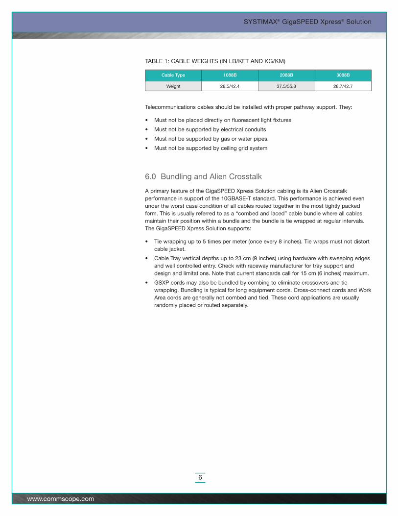
Telecommunications cables should be installed with proper pathway support. They:
• Must not be placed directly on fluorescent light fixtures
• Must not be supported by electrical conduits
• Must not be supported by gas or water pipes.
• Must not be supported by ceiling grid system
6.0 Bundling and Alien Crosstalk
A primary feature of the GigaSPEED Xpress Solution cabling is its Alien Crosstalkperformance in support of the 10GBASE-T standard. This performance is achieved evenunder the worst case condition of all cables routed together in the most tightly packedform. This is usually referred to as a “combed and laced” cable bundle where all cablesmaintain their position within a bundle and the bundle is tie wrapped at regular intervals.The GigaSPEED Xpress Solution supports:
• Tie wrapping up to 5 times per meter (once every 8 inches). Tie wraps must not distortcable jacket.
• Cable Tray vertical depths up to 23 cm (9 inches) using hardware with sweeping edgesand well controlled entry. Check with raceway manufacturer for tray support anddesign and limitations. Note that current standards call for 15 cm (6 inches) maximum.
• GSXP cords may also be bundled by combing to eliminate crossovers and tiewrapping. Bundling is typical for long equipment cords. Cross-connect cords and WorkArea cords are generally not combed and tied. These cord applications are usuallyrandomly placed or routed separately.
Weight 28.5/42.4
Cable Type 1088B
37.5/55.8
2088B
28.7/42.7
3088B
TABLE 1: CABLE WEIGHTS (IN LB/KFT AND KG/KM)
SYSTIMAX® GigaSPEED Xpress® Solution
7
www.commscope.com
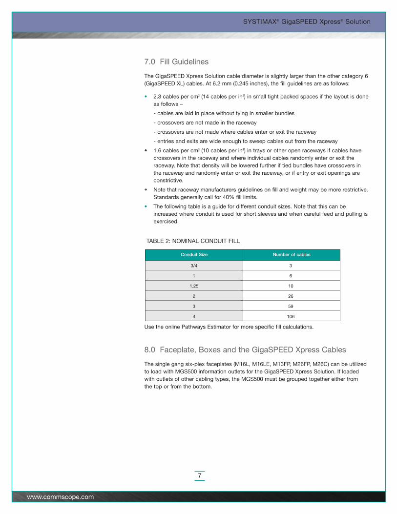
7.0 Fill Guidelines
The GigaSPEED Xpress Solution cable diameter is slightly larger than the other category 6(GigaSPEED XL) cables. At 6.2 mm (0.245 inches), the fill guidelines are as follows:
• 2.3 cables per cm2 (14 cables per in2) in small tight packed spaces if the layout is doneas follows –
- cables are laid in place without tying in smaller bundles
- crossovers are not made in the raceway
- crossovers are not made where cables enter or exit the raceway
- entries and exits are wide enough to sweep cables out from the raceway
• 1.6 cables per cm2 (10 cables per in2) in trays or other open raceways if cables havecrossovers in the raceway and where individual cables randomly enter or exit theraceway. Note that density will be lowered further if tied bundles have crossovers inthe raceway and randomly enter or exit the raceway, or if entry or exit openings areconstrictive.
• Note that raceway manufacturers guidelines on fill and weight may be more restrictive.Standards generally call for 40% fill limits.
• The following table is a guide for different conduit sizes. Note that this can beincreased where conduit is used for short sleeves and when careful feed and pulling isexercised.
Use the online Pathways Estimator for more specific fill calculations.
8.0 Faceplate, Boxes and the GigaSPEED Xpress Cables
The single gang six-plex faceplates (M16L, M16LE, M13FP, M26FP, M26C) can be utilizedto load with MGS500 information outlets for the GigaSPEED Xpress Solution. If loadedwith outlets of other cabling types, the MGS500 must be grouped together either from the top or from the bottom.
3/4
1
1.25
2
3
4
3
6
10
26
59
106
Conduit Size Number of cables
TABLE 2: NOMINAL CONDUIT FILL
SYSTIMAX® GigaSPEED Xpress® Solution
8
www.commscope.com
9.0 GigaSPEED Xpress Cable Installation Alongside Other Cabling
When installing GigaSPEED Xpress cable with other cable types (including PowerSUM,GigaSPEED XL7, XL8 and X10D), ensure that cable types are laid, routed, and/or bundledin separate groups. Spacing from PowerSUM, GigaSPEED XL7, XL8 and X10D is notrequired, but GigaSPEED Xpress cable bundles that include other cable types are notallowed. Each cable type must be routed together. Cable trays and baskets with differentbundles can be used as long as cable types are not mixed, and the GigaSPEED Xpresscables are bundled together. When alternating pulls between different cable types, allocatetray positions for each so that different types will not end up bundled together.
When connector types other than MGS500 are installed in the same 6 port M2000/M2100,8 port M3000, or 12-port M3600 panels, keep the MGS500s grouped together.
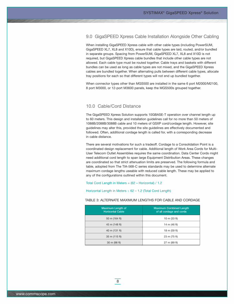
10.0 Cable/Cord Distance
The GigaSPEED Xpress Solution supports 10GBASE-T operation over channel length up to 60 meters. This design and installation guidelines call for no more than 50 meters of1088B/2088B/3088B cable and 10 meters of GSXP cord/cordage length. However, siteguidelines may alter this, provided the site guidelines are effectively documented andfollowed. Often, additional cordage length is called for, with a corresponding decrease in cable distance.
There are several motivations for such a tradeoff. Cordage to a Consolidation Point is acoordinated design replacement for cable. Additional length of Work Area Cords for Multi-User Telecom Outlet Assemblies requires the same coordination. Data Center Cords mightneed additional cord length to span large Equipment Distribution Areas. These changesare coordinated so that strict attenuation limits are preserved. The following formula andtable, adopted from The TIA-568-C series standards may be used to determine alternatemaximum cordage lengths useable with reduced cable length. These may be applied toany of the configurations outlined within this document.
Total Cord Length in Meters = (62 – Horizontal) / 1.2
Horizontal Length in Meters ≤ 62 – 1.2 (Total Cord Length)
50 m (164 ft)
45 m (148 ft)
40 m (131 ft)
35 m (115 ft)
30 m (98 ft)
10 m (33 ft)
14 m (46 ft)
18 m (59 ft)
23 m (75 ft)
27 m (89 ft)
Maximum Length of Horizontal Cable
Maximum Combined Length of all cordage and cords
TABLE 3: ALTERNATE MAXIMUM LENGTHS FOR CABLE AND CORDAGE
SYSTIMAX® GigaSPEED Xpress® Solution
9
www.commscope.com
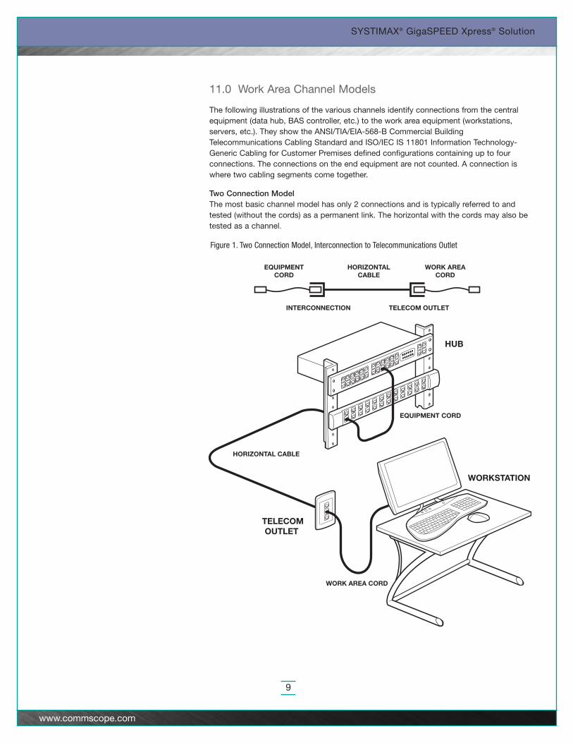
11.0 Work Area Channel Models
The following illustrations of the various channels identify connections from the centralequipment (data hub, BAS controller, etc.) to the work area equipment (workstations,servers, etc.). They show the ANSI/TIA/EIA-568-B Commercial BuildingTelecommunications Cabling Standard and ISO/IEC IS 11801 Information Technology-Generic Cabling for Customer Premises defined configurations containing up to fourconnections. The connections on the end equipment are not counted. A connection iswhere two cabling segments come together.
Two Connection ModelThe most basic channel model has only 2 connections and is typically referred to andtested (without the cords) as a permanent link. The horizontal with the cords may also betested as a channel.
Figure 1. Two Connection Model, Interconnection to Telecommunications Outlet
EQUIPMENT CORD
HORIZONTAL CABLE
WORK AREA CORD
WORKSTATION
TELECOMOUTLET
HUB
WORK AREACORD
EQUIPMENTCORD
HORIZONTALCABLE
TELECOM OUTLETINTERCONNECTION
CROSS-CONNECT CORD
EQUIPMENT CORD
HORIZONTAL CABLE
WORK AREA CORD
HUB
WORKSTATION
WORK AREACORD
EQUIPMENTCORD
HORIZONTALCABLE
TELECOMOUTLET
CROSS-CONNECT AND CORD
SYSTIMAX® GigaSPEED Xpress® Solution
10
www.commscope.com
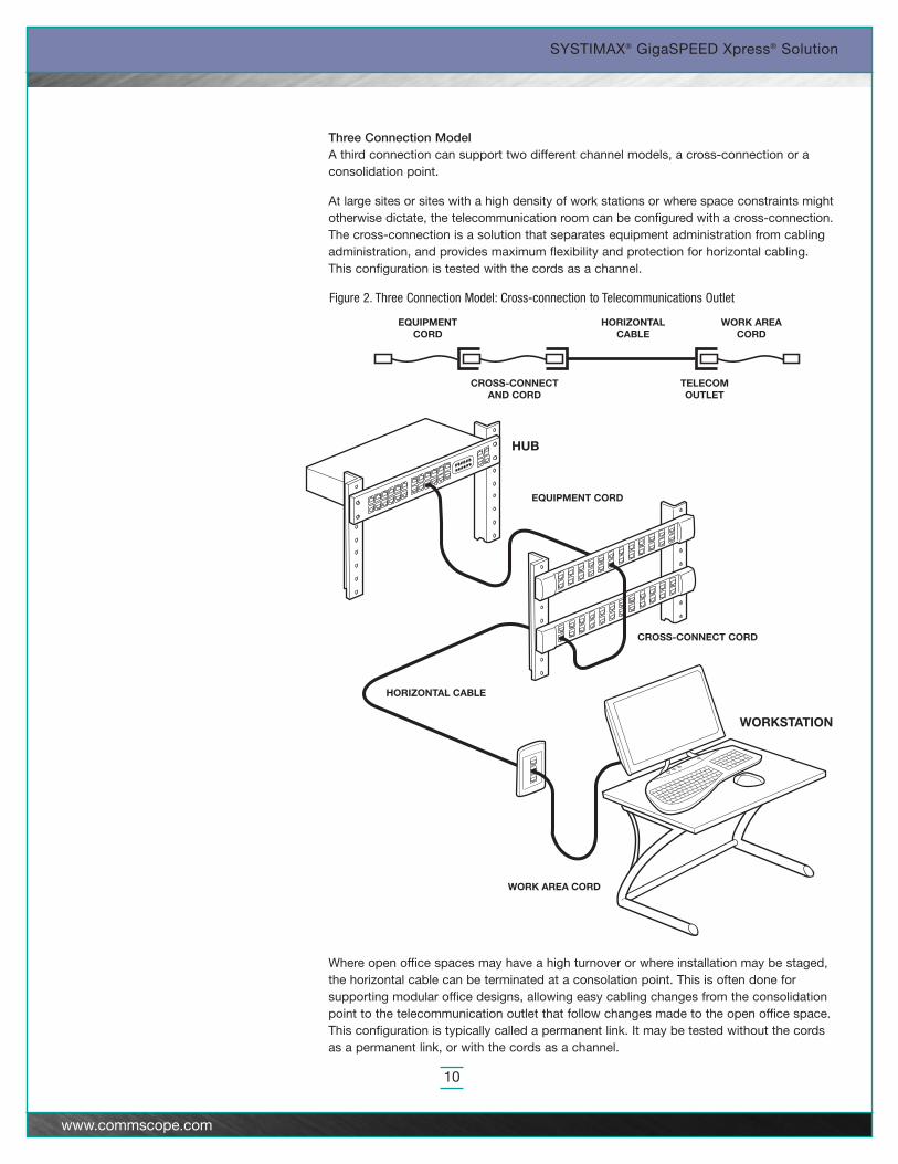
Three Connection ModelA third connection can support two different channel models, a cross-connection or aconsolidation point.
At large sites or sites with a high density of work stations or where space constraints mightotherwise dictate, the telecommunication room can be configured with a cross-connection.The cross-connection is a solution that separates equipment administration from cablingadministration, and provides maximum flexibility and protection for horizontal cabling. This configuration is tested with the cords as a channel.
Where open office spaces may have a high turnover or where installation may be staged,the horizontal cable can be terminated at a consolation point. This is often done forsupporting modular office designs, allowing easy cabling changes from the consolidationpoint to the telecommunication outlet that follow changes made to the open office space.This configuration is typically called a permanent link. It may be tested without the cordsas a permanent link, or with the cords as a channel.
Figure 2. Three Connection Model: Cross-connection to Telecommunications Outlet
SYSTIMAX® GigaSPEED Xpress® Solution
11
www.commscope.com
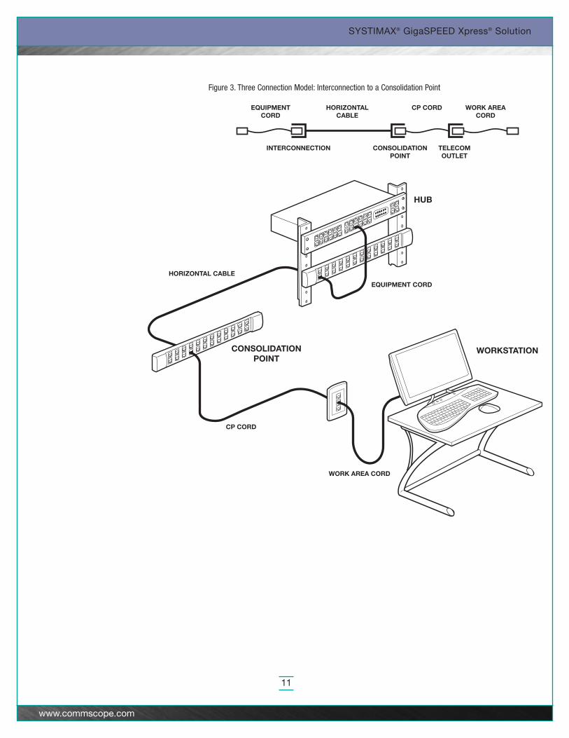
Figure 3. Three Connection Model: Interconnection to a Consolidation Point
EQUIPMENT CORD
HORIZONTAL CABLE
WORK AREA CORD
CP CORD
HUB
WORKSTATIONCONSOLIDATIONPOINT
WORK AREACORD
CP CORDEQUIPMENTCORD
HORIZONTALCABLE
TELECOMOUTLET
CONSOLIDATIONPOINT
INTERCONNECTION
SYSTIMAX® GigaSPEED Xpress® Solution
12
www.commscope.com
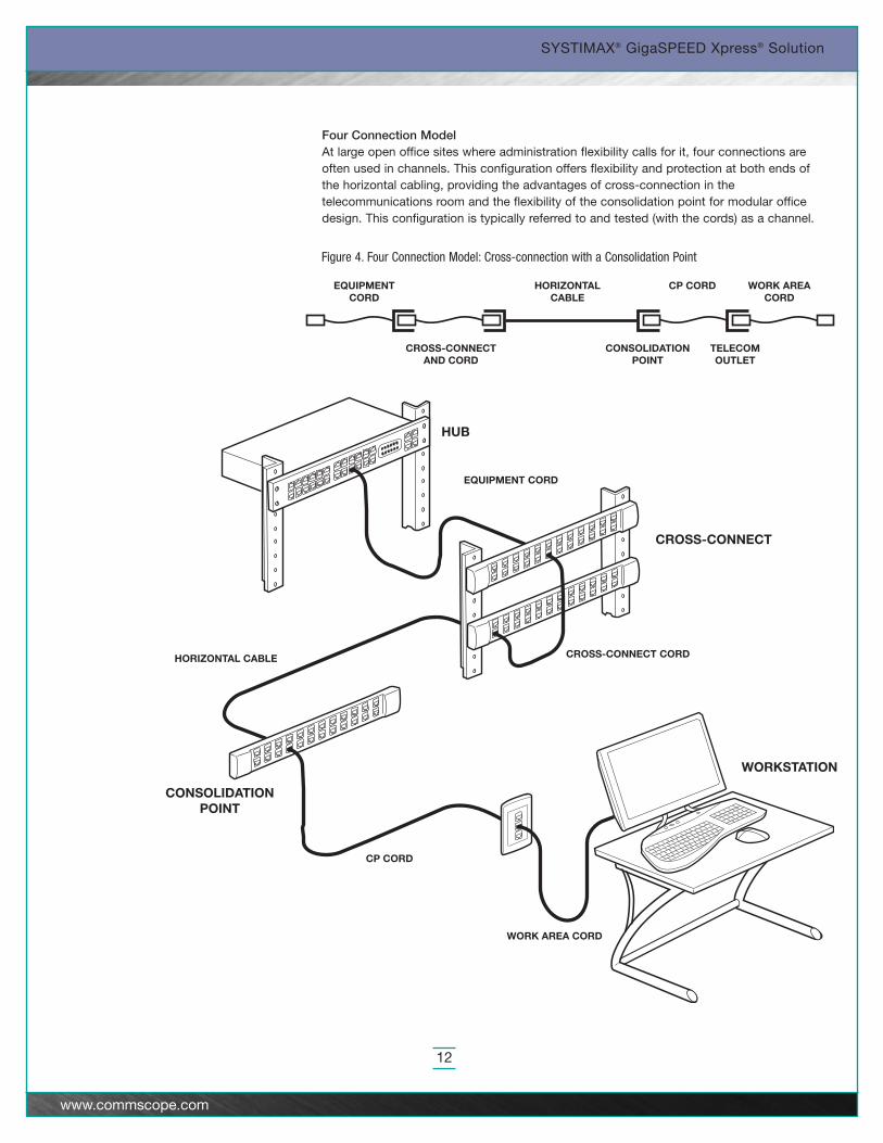
Four Connection ModelAt large open office sites where administration flexibility calls for it, four connections areoften used in channels. This configuration offers flexibility and protection at both ends ofthe horizontal cabling, providing the advantages of cross-connection in thetelecommunications room and the flexibility of the consolidation point for modular officedesign. This configuration is typically referred to and tested (with the cords) as a channel.
Figure 4. Four Connection Model: Cross-connection with a Consolidation Point
HORIZONTAL CABLE
WORK AREA CORD
CP CORD
CROSS-CONNECT CORD
HUB
WORKSTATION
CONSOLIDATIONPOINT
CROSS-CONNECT
EQUIPMENT CORD
WORK AREACORD
CP CORDEQUIPMENTCORD
HORIZONTALCABLE
TELECOMOUTLET
CONSOLIDATIONPOINT
CROSS-CONNECTAND CORD
OFFICE & MANAGEMENT CABLING
(BACKBONE AND HORIZONTALCABLING PER TIA/EIA 568)
ENTRANCEFACILITY
MAIN CROSSCONNECT
COMPUTER ROOM
CORESWITCHES
BACKBONECABLING
HORIZONTALCABLING
EQUIP DIST
AREAS
EQUIP DIST
AREAS
EQUIP DIST
AREAS
EQUIP DIST
AREAS
HORIZONTALCROSSCONNECT
HORIZONTALCROSSCONNECT
LAN, SAN &BACKENDSWITCHES
SYSTIMAX® GigaSPEED Xpress® Solution
13
www.commscope.com
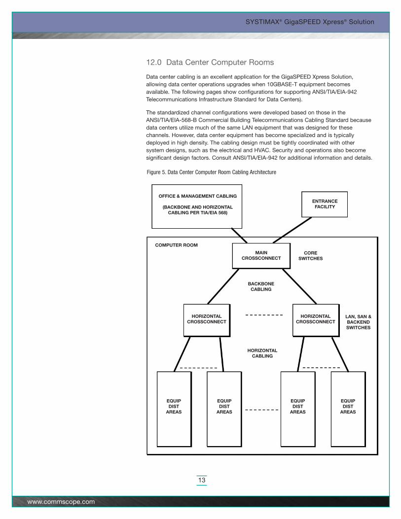
12.0 Data Center Computer Rooms
Data center cabling is an excellent application for the GigaSPEED Xpress Solution,allowing data center operations upgrades when 10GBASE-T equipment becomesavailable. The following pages show configurations for supporting ANSI/TIA/EIA-942Telecommunications Infrastructure Standard for Data Centers).
The standardized channel configurations were developed based on those in theANSI/TIA/EIA-568-B Commercial Building Telecommunications Cabling Standard becausedata centers utilize much of the same LAN equipment that was designed for thesechannels. However, data center equipment has become specialized and is typicallydeployed in high density. The cabling design must be tightly coordinated with othersystem designs, such as the electrical and HVAC. Security and operations also becomesignificant design factors. Consult ANSI/TIA/EIA-942 for additional information and details.
Figure 5. Data Center Computer Room Cabling Architecture
HORIZONTAL CABLE
HORIZONTAL CABLE
EQUIPMENT CORD
EQUIPMENT CORD
REMOTE EQUIPMENTCORD
C-SWITCH S-SWITCH
SWITCH SERVER
HORIZONTALSWITCH TO
SERVER
BACKBONE CORESWITCH TO SERVER
SWITCH
REMOTEEQUIPMENT
CORD
EQUIPMENTCORD
HORIZONTAL OR BACKBONE CABLE
INTERCONNECTIONINTERCONNECTION
REMOTE EQUIPMENTCORD
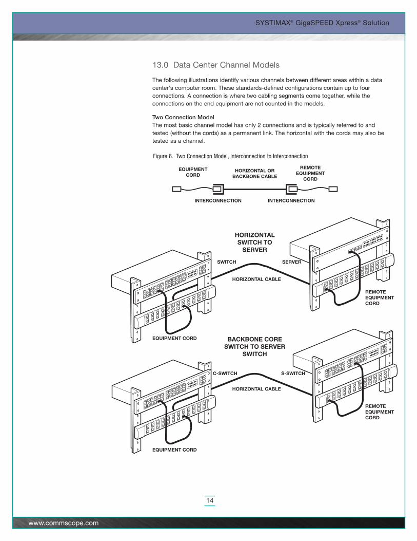
Figure 6. Two Connection Model, Interconnection to Interconnection
SYSTIMAX® GigaSPEED Xpress® Solution
14
www.commscope.com
13.0 Data Center Channel Models
The following illustrations identify various channels between different areas within a datacenter's computer room. These standards-defined configurations contain up to fourconnections. A connection is where two cabling segments come together, while theconnections on the end equipment are not counted in the models.
Two Connection ModelThe most basic channel model has only 2 connections and is typically referred to andtested (without the cords) as a permanent link. The horizontal with the cords may also betested as a channel.
REMOTEEQUIPMENT CORD
HORIZONTAL CABLE
CROSS-CONNECT CORD
EQUIPMENT CORD
REMOTEEQUIPMENT
CORD
EQUIPMENTCORD
HORIZONTALCABLE
EQUIPMENTINTERCONNECT
CROSS-CONNECTAND CORD
EQUIPMENTDISTRIBUTION
AREA
HORIZONTALDISTRIBUTION
AREA
SYSTIMAX® GigaSPEED Xpress® Solution
15
www.commscope.com
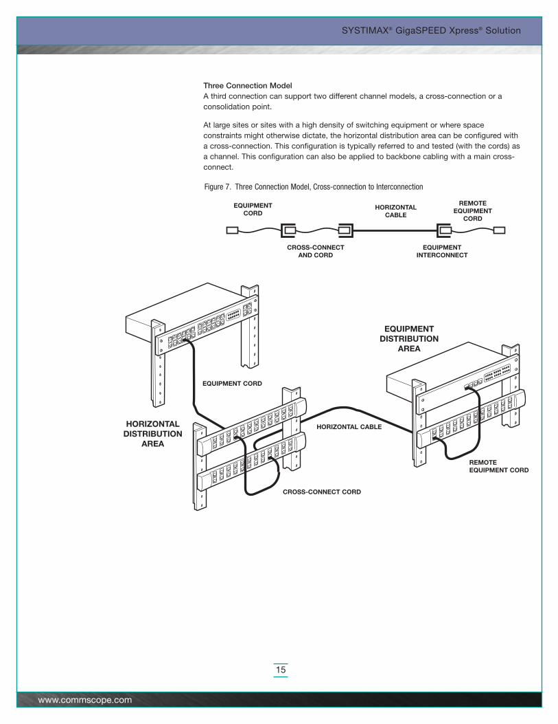
Three Connection ModelA third connection can support two different channel models, a cross-connection or aconsolidation point.
At large sites or sites with a high density of switching equipment or where spaceconstraints might otherwise dictate, the horizontal distribution area can be configured witha cross-connection. This configuration is typically referred to and tested (with the cords) asa channel. This configuration can also be applied to backbone cabling with a main cross-connect.
Figure 7. Three Connection Model, Cross-connection to Interconnection
SYSTIMAX® GigaSPEED Xpress® Solution
16
www.commscope.com
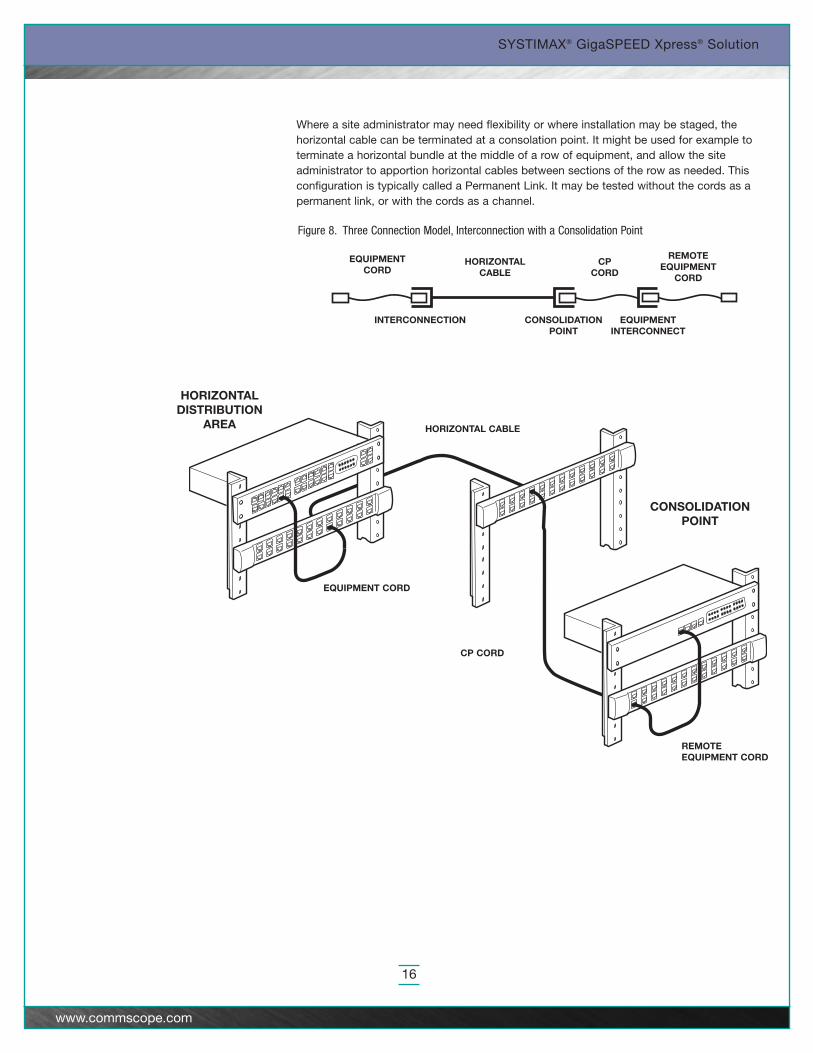
Where a site administrator may need flexibility or where installation may be staged, thehorizontal cable can be terminated at a consolation point. It might be used for example toterminate a horizontal bundle at the middle of a row of equipment, and allow the siteadministrator to apportion horizontal cables between sections of the row as needed. Thisconfiguration is typically called a Permanent Link. It may be tested without the cords as apermanent link, or with the cords as a channel.
Figure 8. Three Connection Model, Interconnection with a Consolidation Point
REMOTEEQUIPMENT CORD
HORIZONTAL CABLE
CP CORD
CONSOLIDATIONPOINT
HORIZONTALDISTRIBUTION
AREA
EQUIPMENT CORD
REMOTEEQUIPMENT
CORD
EQUIPMENTCORD
HORIZONTALCABLE
CP CORD
EQUIPMENTINTERCONNECT
CONSOLIDATIONPOINT
INTERCONNECTION
REMOTEEQUIPMENTCORD
CP CORD
EQUIPMENT CORD
CROSS-CONNECTCORD
HORIZONTALCABLE
SWITCH
SERVER
EQUIPMENTDISTRIBUTION
AREA
HORIZONTALDISTRIBUTION
AREA
HORIZONTALCROSS-CONNECT
CONSOLIDATIONPOINT
REMOTEEQUIPMENT
CORD
EQUIPMENTCORD
HORIZONTALCABLE
CP CORDCROSS-CONNECT
AND CORD
SYSTIMAX® GigaSPEED Xpress® Solution
17
www.commscope.com
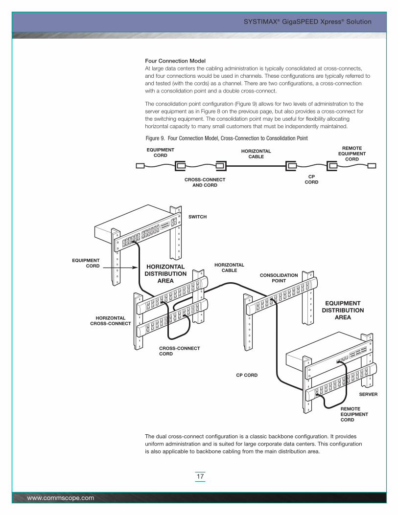
Four Connection ModelAt large data centers the cabling administration is typically consolidated at cross-connects,and four connections would be used in channels. These configurations are typically referred toand tested (with the cords) as a channel. There are two configurations, a cross-connectionwith a consolidation point and a double cross-connect.
The consolidation point configuration (Figure 9) allows for two levels of administration to theserver equipment as in Figure 8 on the previous page, but also provides a cross-connect forthe switching equipment. The consolidation point may be useful for flexibility allocatinghorizontal capacity to many small customers that must be independently maintained.
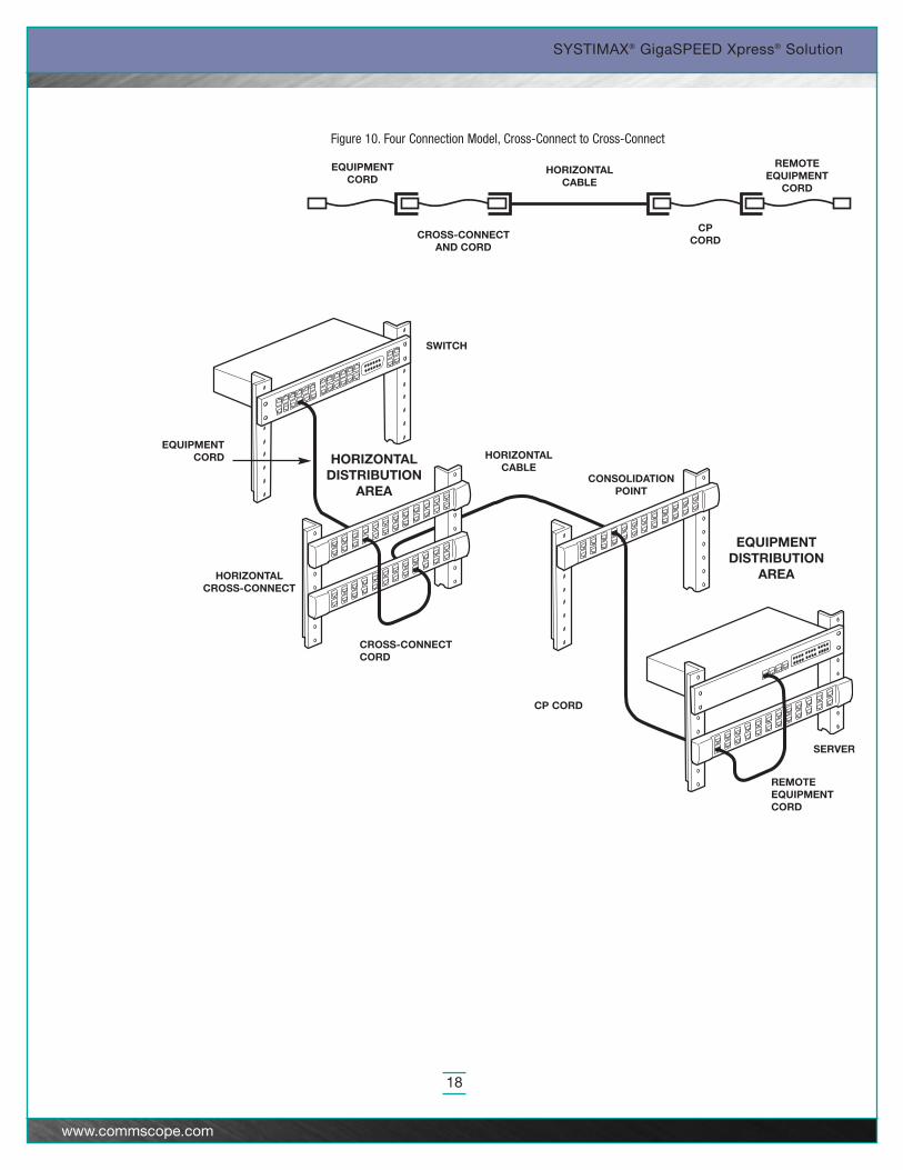
The dual cross-connect configuration is a classic backbone configuration. It providesuniform administration and is suited for large corporate data centers. This configurationis also applicable to backbone cabling from the main distribution area.
Figure 9. Four Connection Model, Cross-Connection to Consolidation Point
REMOTEEQUIPMENTCORD
CP CORD
EQUIPMENT CORD
CROSS-CONNECTCORD
HORIZONTALCABLE
SWITCH
SERVER
EQUIPMENTDISTRIBUTION
AREA
HORIZONTALDISTRIBUTION
AREA
HORIZONTALCROSS-CONNECT
CONSOLIDATIONPOINT
REMOTEEQUIPMENT
CORD
EQUIPMENTCORD
HORIZONTALCABLE
CP CORDCROSS-CONNECT
AND CORD
SYSTIMAX® GigaSPEED Xpress® Solution
18
www.commscope.com
Figure 10. Four Connection Model, Cross-Connect to Cross-Connect
SYSTIMAX® GigaSPEED Xpress® Solution
19
www.commscope.com
The installation of SYSTIMAX GigaSPEED Xpress is similar to SYSTIMAX GigaSPEEDX10D and the installation information in SYSTIMAX® GigaSPEED® X10D Solution Designand Installation Guidelines should be followed. Note that 2088B cable and Xpresscordage does not utilize the separator tapes. You may also find the following documentsuseful for installing and handling the GigaSPEED Xpress cables, cords, and apparatus:
• SYSTIMAX GigaSPEED X10D Solution Design and Installation Guideline for UTP
• SYSTIMAX 1100 GS5-Type Modular Panel Installation Instructions
• SYSTIMAX M2000 Modular Patch Panel
• SYSTIMAX M2100 Modular Patch Panel
• SYSTIMAX M3000 Modular Patch Panel
• SYSTIMAX M3600 Modular Patch Panel Installation Instructions
• SYSTIMAX PATCHMAX GS5 Modular Panel Installation Instructions
• SYSTIMAX VP360-2U-RMBKT Kit for Rack Mounting VisiPatch® 360 Panel SystemInstallation Instructions
• SYSTIMAX VisiPatch 360 Wall Mounted Panel System Installation Instructions
• RFE (Raised Floor Enclosure)
© 2010 CommScope, Inc. All rights reserved.
Visit our Web site at www.commscope.com or contact your local CommScope representative or BusinessPartner for more information. All trademarks identified by ® or ™ are registered trademarks or trademarks, respectively, of CommScope.
This document is for planning purposes only and is not intended to modify or supplement any specifications or warranties relating to SYSTIMAX products or services.
09/10 MI-B-6