Embed Size (px)
Citation preview

CTP 2E SYSTEM INSTALLATION MANUAL
FOR THE EnduraTM
PN 02231 Rev. 1.2
June 28, 2001 © MKS Instruments
Endura is a trademark of Applied Materials
CTP 2E System Installation Manual, Rev. 1.2, June 28, 2001 1
TABLE OF CONTENTS 1.0 INTRODUCTION Pg. 2 2.0 CTP 2E CONTROLLER INSTALLATION Pg. 2
2.1 Key Components Pg. 2 2.2 Equipment Lay Out, Facilitation, and Power Pg. 2
3.0 ENDURATM SECS COMMUNICATIONS SET-UP Pg. 4
3.1 Enabling access to the Endura software Pg. 4 3.2 Enabling the Endura RGA SECS port Pg. 4 3.3 Configuring the Endura RGA SECS port Pg. 5 3.4 Event Constants Pg. 5
4.0 MODULE HARDWARE INSTALLATION Pg. 7
4.1 RESIST-TORR on O/D Chambers E and F Pg. 7 4.1.1 Key Components Pg. 7 4.1.2 Equipment Lay Out, Facilitation, and Power Pg. 7 4.1.3 Vacuum Hookup and Filament Interlock Pg. 7
4.2 HPQ 2 on Clamped Degas Chambers C, D, E Pg. 10 4.2.1 Key Components Pg. 10 4.2.2 Equipment Lay Out, Facilitation, and Power Pg. 10 4.2.3 Vacuum Hookup and Filament Interlock Pg. 10
4.3 HPQ 2S on PVD Ti, Al, TiN, TiTiN Chambers 1, 2, 3, 4 Pg. 13 4.3.1 Key Components Pg. 13 4.3.2 Equipment Lay Out, Facilitation, and Power Pg. 13 4.3.3 Vacuum Hookup and Filament Interlock Pg. 13
4.4 V1000 B on PVD Ti, Al Chambers 1, 2, 3, 4 Pg. 16 4.4.1 Key Components Pg. 16 4.4.2 Equipment Lay Out, Facilitation, and Power Pg. 16 4.4.3 Vacuum Hookup and Filament Interlock Pg. 16
4.5 HPQ 2 on Preclean II Chambers A, C, D Pg. 19 4.5.1 Key Components Pg. 19 4.5.2 Equipment Lay Out, Facilitation, and Power Pg. 19 4.5.3 Vacuum Hookup and Filament Interlock Pg. 19
4.6 HPQ 2S on Preclean II Chambers A, C, D Pg. 22 4.6.1 Key Components Pg. 22 4.6.2 Equipment Lay Out, Facilitation, and Power Pg. 22 4.6.3 Vacuum Hookup and Filament Interlock Pg. 22
CTP 2E System Installation Manual, Rev. 1.0, August 21, 2000 2
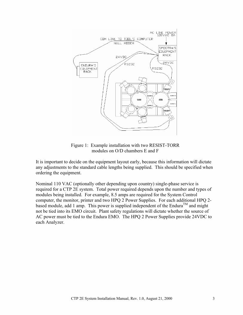
1.0 INTRODUCTION This document addresses system installation of the MKS Cluster Tool Profiler, Level 2, for the Applied Materials EnduraTM - the CTP 2E. A CTP 2E system comprises a controller, software and one to ten modules. A module is a specific sensor package, on a particular type of chamber and its associated software for automatic operation. Other manuals, including the Process Eye 2000 Software Manual (LP101015) and the User Manual (PN 02225), describe use of the system and its components. When it becomes necessary to service or move components of the system, please refer to the safety precautions in each of the sensor manuals before handling any electrical components. The detailed information contained in those manuals is not duplicated here. This manual describes installation of the CTP 2E controller (computer), configuration of the Endura software settings and module-specific hardware installation. The CTP 2E controller should be pre-configured with Process Eye 2000 and the Module software for those specific modules for each installation. An MKS service representative will generally be involved in initial installation of the system. A qualified Applied Materials Customer Engineer is required to configure the Endura per the instructions in section 3.0, below. 2.0 CTP 2E CONTROLLER INSTALLATION 2.1 Key Components System Control Computer Monitor Keyboard and Mouse Printer (optional) Equipment Rack or “Ergo” cart (optional) RS-232 Null modem cable (30’) 2.2 Equipment Lay Out, Facilitation and Power Figure 1 depicts an example installation with two RESIST-TORR modules on the two O/D chambers E and F. The equipment rack, containing the System Control Computer, monitor, keyboard, mouse, printer and HPQ 2 Power Supplies, is located in the gray area along side the Endura. The control computer and power supplies can also be mounted in a movable “Ergo” cart. The two Analyzer and Control assemblies are mounted to the RGA Port Adapters on the backs of Chambers E and F. The RS-232 null modem connection for SECS communications is made to the Endura System Controller. A 9-pin D-connector labeled P9 Ch 2 is the standard port for the RGA SECS communications link. It is typically found in the upper right hand corner of the cable connection area of the System Controller, near the selection switch for the monitors. The Analyzers are connected to the Control Computer via the RS-232 cables and 24 VDC is made available from the individual power supply units. In some installations, the individual power bricks are positioned under the Endura frame near the chamber with the sensor they supply.
CTP 2E System Installation Manual, Rev. 1.0, August 21, 2000 3
Figure 1: Example installation with two RESIST-TORR
modules on O/D chambers E and F It is important to decide on the equipment layout early, because this information will dictate any adjustments to the standard cable lengths being supplied. This should be specified when ordering the equipment. Nominal 110 VAC (optionally other depending upon country) single-phase service is required for a CTP 2E system. Total power required depends upon the number and types of modules being installed. For example, 8.5 amps are required for the System Control computer, the monitor, printer and two HPQ 2 Power Supplies. For each additional HPQ 2-based module, add 1 amp. This power is supplied independent of the EnduraTM and might not be tied into its EMO circuit. Plant safety regulations will dictate whether the source of AC power must be tied to the Endura EMO. The HPQ 2 Power Supplies provide 24VDC to each Analyzer.

CTP 2E System Installation Manual, Rev. 1.0, August 21, 2000 4
3.0 ENDURATM SECS COMMUNICATIONS SET-UP 3.1 Enabling access to the EnduraTM software A user can only modified the Endura software with the appropriate User ID and User Password to the tool. To add or modify the RGA SECS communications settings requires signing on using the AMAT password. Once the password is obtained, the following steps are used to enable the RGA SECS Port and configure the Endura to communicate with the CTP2E Control Computer. This should be done a qualified AMAT CE.
1) Enable the Endura Control Screen you are using, System or Remote, by selecting the appropriate setting on the light pen select switch located at the back of the Endura System Controller. Typically the System screen is accessible from the clean room front of the tool and the Remote screen is located in the gray area behind the tool.
2) Using the Endura light pen, select System from the Main Menu bar located at the top of the screen.
3) Select Login/Logout. 4) Enter the User ID (AMAT) using the displayed alpha/numeric keypad and click
Enter. The User ID must be AMAT to modify any RGA SECS communications settings.
5) Enter the User Password and click Enter. The AMAT password is available from the AMAT support engineer.
6) Click on the word processing and ensure that the User ID is displayed. 3.2 Enabling the EnduraTM RGA SECS port A machine-specific (i.e., serial number specific) password is required to enable use of the Endura RGA SECS port. This item may be purchased from Applied Materials. It may also be purchased through the MKS Spectra Products group as part of a CTP 2E system. The password is a hexadecimal number that is entered into the RGA Password System Constant.
1) At the Endura monitor, select Misc. from the Main Menu bar. 2) Select System Constants. 3) Select Sequentially Display System Constants. 4) Confirm that the value displayed in System Constant ID # 1, Serial Number, is the
one for which the password applies. 5) Select Sequential Constants and using the dashed blue scroll feature at the bottom of
the screen, find constant number 3179. 6) Enter the hexadecimal Password for RGA. 7) Click the number once to enter it 8) Confirm the following standard AMAT System Constants to control
communications settings. Correct any that might have been changed: 6814 RGAS Serial Channel 10 6815 RGAS Baud Rate 9600 6816 RGAS Control Option 00000001 6817 RGAS Format Option 00000021 6818 RGAS Retry Count 3 6819 RGAS Device ID 0000000A 6820 RGAS T1 Receive Timeout 400 msec 6821 RGAS T2 Protocol Timeout 3000 msec

CTP 2E System Installation Manual, Rev. 1.0, August 21, 2000 5
6822 RGAS T3 Reply Timeout 10 sec 6823 RGAS T4 Reply Timeout 10 sec 6824 RGAS T5 Conversation Timeout Not used
3.3 Configuring the EnduraTM RGA SECS port After entering the RGA SECS Password, the RGA SECS Communications screen is accessible. The following steps enable communications with the Endura and specify the type of information being delivered to our computer.
1) At the EnduraTM monitor, select Misc. from the Main Menu bar. 2) Select Maintenance. 3) Select RGA SECS communications. 4) On the RGA command line, select Enabled. 5) On the RGA Port command line, select 10. 6) On the RGA Device ID command line, select 10. 7) On the Applied Tool is command line, select Equipment/Master. 8) Under Diag, select Disable Ping, Disable Loop. 9) In the list of Event enable/disable selections, enable Gate Valve and Slit Valve. All
others are disabled. 3.4 Event Constants The Event Configuration of the Endura must be modified to enable the sending of red and yellow alarms to the Endura screen when the RGA detects an issue. It must also be configured to prevent the accumulation of excessive slit valve activity information. This is done using the Event Configure menu. The following steps enable Red Line Alarms to be sent to the control screen.
1) Select Misc. from the Main Menu Bar of the Endura. 2) Select Mainframe Operating Parameters and then Event Configure. 3) Using the dashed scroll feature at the bottom of the screen, proceed to Event
Number 2194: “RGA Alarm 0 has been cleared for unknown, not used”. 4) Note that at the top of the screen, the event destination reads Alarm display line. If
it does not, click on the blue characters and select Control whether an event is shown on the Alarm display line. To the right of the line describing 2194, an option can be toggled to “sent” or “not sent”. Toggle this value to “Sent”.
The following steps enable Yellow Line Alarms to be sent to the control screen.
1) Using the dashed scroll feature at the bottom of the screen, proceed to Event Number 1683: “RGA Alarm 0 has been cleared for unknown, not used”.
2) After selecting Alarm Display line for the Event Destination, set Event 1683 to “Sent”
Enabling sending of Gate Valve and Slit Valve events in the RGA SECS Communications screen causes those events to be noted in the Endura event log. To avoid filling the event log with these normal valve events, disable these events from showing up on the alarm line or in the event log as follows.
1) Using the dashed scroll feature at the bottom of the screen, proceed to Event Number 1568: RGA event Cassette Removed for Unknown .

CTP 2E System Installation Manual, Rev. 1.0, August 21, 2000 6
2) After selecting Alarm Display line for the Event Destination, set Event 1568 to “not sent”
3) Next select Control whether an event is put in the Event log file as the Event Destination
4) Set Event 1568 to “not sent” 5) If the Event Log destination says “Forced”, this is due to one or both of the other
possible destinations for the event being set to “Sent”. Make sure that the destinations for the SECS Host and Auxilary SECS Host are also set to “Not Sent” and then check the Event Log destination and ensure that it is also set to “Not Sent”.

CTP 2E System Installation Manual, Rev. 1.0, August 21, 2000 7
4.0 MODULE HARDWARE INSTALLATION 4.1 RESIST-TORR on O/D Chambers E and F 4.1.1 Key Components RESIST-TORR Analyzer with tungsten filaments: PN 292-410-000 RESIST-TORR Controller: PN 291-000 HPQ 2 Power Supply: PN 842-120 X-Trip/Gate-Valve Interlock Assembly (50’): PN 02123 Analyzer Housing: PN 710051007 RGA Port Adapter (as required): PN 704600050 RS-232 cable (30’): PN 565-030 4.1.2 Equipment Lay Out, Facilitation and Power Figure 1 shows a typical module installation. The sensor of the module is connected by a communication cable to the CTP 2E system controller and by a power cable to its power supply. Pneumatic interlock is also used in this module as shown later in Figure 2. The power supply brick for each RESIST-TORR module requires 90 VA of 50-60Hz AC at 100-240V, which is converted to 24VDC at 2.5 amps for the analyzer. 4.1.3 Vacuum Hookup and Filament Interlock The RESIST-TORR attaches directly to the back of the Orienter/Degas chamber through a NW-40 flange. On some Enduras, this port is not already present and an RGA Port Adapter Plate must be installed. If not already present, install an RGA Port Plate as follows:
1@ RGA Port Adapter Plate (#704600050) 1@ Bulkhead clamp kit (#710001241) 6@ #10-24 x 3/4” socket screws (#210304190) 6@ #10 split lock-washers (#270406553)
1) Vent the Endura Buffer chamber 2) Remove the optical assembly tube from the O/D chamber 3) Slide the chamber lid back to expose the top mounting screws of the chamber back plate. 4) Remove the 5 or 7 top mounting Allen screws. 5) Remove the 2 bottom mounting screws from beneath the chamber. 6) Remove the backing plate. 7) Inspect the sealing surface of the RGA Port Adapter Plate for scratches and carefully
polish out any imperfections. 8) Wipe the vacuum surfaces with IPA and a lint free cloth. 9) Mount the RGA Adapter Port Plate to the back of the O/D chamber. 10) Reinstall the chamber lid and optical assembly. Mount the RESIST-TORR head to the chamber Port Plate as follows: 1) The head of the RESIST-TORR should be mounted in its housing (mitered rt. angle NW-
40 to 2¾” CF Analyzer Chamber #710051007) prior to mounting the housing to the Port Plate. The preferred orientation of the RESIST-TORR head alignment pin is opposite the housing side-port (opposite the O/D chamber).
CTP 2E System Installation Manual, Rev. 1.0, August 21, 2000 8
2) Mount the housing to the Port Plate using the bulkhead clamp and O-ring, orienting the Analyzer toward the ground to minimize obstruction to workers around the tool.
3) Connect the pneumatic interlock by teeing into the 1/8” poly line on the OPEN side of the chamber Gate Valve (see Figure 2) and be sure the X-Trip connector is locked in place.
4) Pump down the chamber. 5) Connect the communication and power cable to the RESIST-TORR controller. 6) When the analyzer is running and has had a 20-30 minute warm up period, leak check all
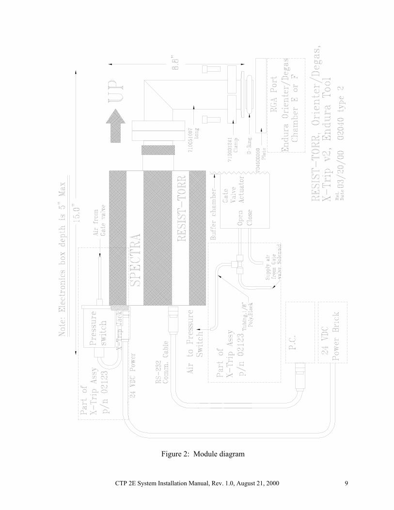
vacuum connections. Primary filament control is provided through the state-engine design of the CTP 2E system control software, which relies upon the tool state information it obtains via the Endura RGA SECS port. This module employs a hardware backup for filament protection that activates whenever the Buffer Gate Valve is closed. This turns off the filament when there is a chance that the chamber might be vented. An electrical “open” in the X-Trip circuit turns off the filament. When the Gate Valve is opened again, the filament can turn back on. As shown in Figure 2, a pressure sensitive switch is connected to the pneumatic “open” control line of the Buffer Gate Valve using a tee fitting. The electrical cable from the switch is tied directly to the X-Trip jack on the back of the RESIST-TORR controller.
CTP 2E System Installation Manual, Rev. 1.0, August 21, 2000 9
Figure 2: Module diagram
CTP 2E System Installation Manual, Rev. 1.0, August 21, 2000 10
4.2 HPQ 2 on Clamped Degas Chambers C, D and E 4.2.1 Key Components HPQ 2 Analyzer with tungsten filaments: PN 292-410-000 HPQ 2 Controller: PN 291-000 HPQ 2 Power Supply: PN 842-120 X-Trip/Gate-Valve Interlock Assembly (50’): PN 02123 Analyzer Housing: PN 710051004 RS-232 cable (30’): PN 565-030 4.2.2 Equipment Lay Out, Facilitation and Power Figure 1 shows an example of module installation. The sensor of the module is connected by a communication cable to the CTP 2E system controller and by a power cable to its power supply. Pneumatic interlock is also used in this module as shown later in Figure 3. The power supply brick for each HPQ 2 module requires 90 VA of 50-60Hz AC at 100-240V, which is converted to 24VDC at 2.5 amps for the analyzer. 4.2.3 Vacuum Hookup and Filament Interlock The HPQ 2 attaches directly to the side of the Clamped Degas chamber through a 2¾” CF flange. Mount the HPQ 2 head to the chamber as follows: 1) The head of the HPQ 2 should be mounted in its housing (mitered rt. angle 2¾” CF
Analyzer Chamber #710051004) prior to mounting the housing to the Endura. The preferred orientation of the HPQ 2 head alignment pin is opposite the housing side-port (opposite the Clamped Degas chamber).
2) Choose one of the 2¾” CF flange side ports on the Clamped Degas chamber to attach the analyzer housing. The port should be selected to reduce the profile of the complete sensor installation as much as possible. Orienting the housing so that the controller points toward the floor makes it easier for maintenance personnel to access to the vacuum chamber and improves cable dress to reduce the chance of accidental disturbance. If an obstruction such as the ion gauge interferes with this preferred position, any rotation of the analyzer from horizontal to vertical is acceptable. NOTE! The HPQ 2 control electronics should not be inverted – rotate and reinstall the sensor in the housing, if necessary, to ensure that the side panel reads right side up and air can flow freely through the electronics.
3) Mount the housing to the selected port using the silvered screws provided. 4) Connect the pneumatic interlock by teeing into the 1/8” poly line on the OPEN side of the
chamber Gate Valve (see Figure 3) and be sure the X-Trip connector is locked in place. 5) Pump down the chamber. 6) Connect the communication and power cable to the HPQ 2 controller. 7) When the analyzer is running and has had a 20-30 minute warm up period, leak check all
vacuum connections. Primary filament control is provided through the state-engine design of the CTP 2E system control software, which relies upon the tool state information it obtains via the Endura RGA SECS port. This module employs a hardware backup for filament protection that activates

CTP 2E System Installation Manual, Rev. 1.0, August 21, 2000 11
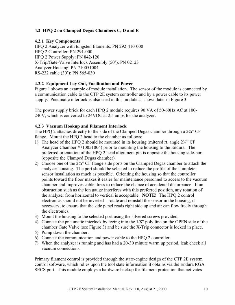
whenever the chamber Gate Valve is closed. This turns off the filament when there is a chance that the chamber might be vented. An electrical “open” in the X-Trip circuit turns off the filament. When the Gate Valve is opened again, the filament can turn back on. As shown in Figure 3, a pressure sensitive switch is connected to the pneumatic “open” control line of the chamber Gate Valve using a tee fitting. The electrical cable from the switch is tied directly to the X-Trip jack on the back of the HPQ 2 controller.
CTP 2E System Installation Manual, Rev. 1.0, August 21, 2000 12
Figure 3: Module diagram
CTP 2E System Installation Manual, Rev. 1.0, August 21, 2000 13
4.3 HPQ 2S on PVD Ti, Al and TiN, TiTiN Chambers 1, 2, 3 and 4 4.3.1 Key Components HPQ 2S Analyzer with tungsten filaments: PN 292-410-000 HPQ 2S Controller: PN 291-000 HPQ 2 Power Supply: PN 842-120 Ion Gauge: PN 780012300 X-Trip/Gate-Valve Interlock Assembly (50’): PN 02123 Analyzer Housing: PN 02030-E Bakeout jacket (optional): PN 105342060 HPQ 2S Wiring Harness: PN 02047 RS-232 cable (30’): PN 565-030 4.3.2 Equipment Lay Out, Facilitation and Power Figure 1 shows an example of module installation. The sensor of the module is connected by a communication cable to the CTP 2E system controller and by a power cable to its power supply. Pneumatic interlock is also used in this module as shown later in Figure 4. The power supply brick for each HPQ 2S module requires 100 VA of 50-60Hz AC at 100-240V, which is converted to 24VDC at 3 amps for the analyzer and gauge. The optional 200ºC bakeout jacket requires 70W at 110VAC during bakeout. 4.3.3 Vacuum Hookup and Filament Interlock The HPQ 2S attaches directly to the side of the PVD chamber through a 2¾” CF flange. Mount the HPQ 2S system to the chamber as follows: 1) The HPQ 2S analyzer and gauge should be mounted in the system housing (mitered rt.
angle 2¾” CF Analyzer Chamber #02030-E) prior to mounting the housing to the Endura. The recommended configuration is with gauge at the housing “elbow” (far from the tool connection) and the HPQ 2S analyzer at the “tee”. The preferred orientation of the HPQ 2S head alignment pin is opposite the housing side-port (opposite the PVD chamber).
2) Choose one of the 2¾” CF flange side ports on the PVD chamber to attach the analyzer housing. The port should be selected to reduce the profile of the complete sensor installation as much as possible. Orienting the housing so that the controller points toward the floor makes it easier for maintenance personnel to access to the vacuum chamber and improves cable dress to reduce the chance of accidental disturbance. If an obstruction such as the ion gauge interferes with this preferred position, any rotation of the analyzer from horizontal to vertical is acceptable. NOTE! The HPQ 2S control electronics should not be inverted – rotate and reinstall the sensor, if necessary, to ensure that the side panel reads right side up and air can flow freely through the electronics.
3) Mount the housing to the selected port using the silvered screws provided. 4) Connect the pneumatic interlock by teeing into the 1/8” poly line on the OPEN side of the
chamber Gate Valve (see Figure 4) and be sure the X-Trip connector is locked in place. 5) If a heater jacket has been purchased, install it to wrap around the housing. 6) Pump down the chamber. 7) Connect the communication and power cable to the HPQ 2S controller.

CTP 2E System Installation Manual, Rev. 1.0, August 21, 2000 14
8) When the analyzer is running and has had a 20-30 minute warm up period, leak check all vacuum connections.
If the optional bakeout heater jacket has been purchased and installed, it can be plugged into an AC extension cord when baking is required. Baking is not recommended at any time other than after installation. Note that bakeout times of ONLY two to eight hours are recommended depending upon how clean the analyzer and housing were initially and the ultimate vacuum background desired. Note that the sensor will not give good data while baking. Do NOT leave the jacket on all the time. Primary filament control is provided through the state-engine design of the CTP 2E system control software, which relies upon the tool state information it obtains via the Endura RGA SECS port. This module employs a hardware backup for filament protection that activates whenever the chamber Gate Valve is closed. This turns off the filament when there is a chance that the chamber might be vented. An electrical “open” in the X-Trip circuit turns off the filament. When the Gate Valve is opened again, the filament can turn back on. As shown in Figure 4, a pressure sensitive switch is connected to the pneumatic “open” control line of the chamber Gate Valve using a tee fitting. The electrical cable from the switch is tied directly to the X-Trip jack on the back of the HPQ 2 controller. The ion gauge filament is also protected.
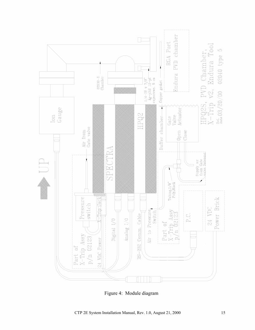
CTP 2E System Installation Manual, Rev. 1.0, August 21, 2000 15
Figure 4: Module diagram
CTP 2E System Installation Manual, Rev. 1.0, August 21, 2000 16
4.4 Vision 1000 B on PVD Ti, Al Chambers 1, 2, 3 and 4 4.4.1 Key Components V1000 B Analyzer, 100 amu, tungsten filaments: PN 212-120-020 MicroVision Plus Controller: PN 235-000 MicroVision Power Supply: PN 842-120 Analyzer Housing: PN 800010314 Pneumatic Inlet Valve: PN 710002303 Manual-Override Ball Valve: PN 710001600 25 PSIG Pressure Switch: PN 128752709 Bakeout jacket: PN 105342008 RS-232 cable (30’): PN 565-030 4.4.2 Equipment Lay Out, Facilitation and Power Figure 1 shows an example of module installation. The sensor of the module is connected by a communication cable to the CTP 2E system controller and by a power cable to its power supply. This module incorporates automated isolation from the tool chamber and has pneumatic filament protection interlock, as shown later in Figure 5. The power supply brick for each MicroVision Plus module requires 80 VA of 50-60Hz AC at 100-240V, which is converted to 24VDC at 2 amps for the analyzer. The 200ºC bakeout jacket requires 126W at 110VAC during bakeout. 4.4.3 Vacuum Hookup and Filament Interlock The V1000 B attaches directly to the side of the PVD chamber through a 2¾” CF flange. Mount the V1000 B head to the chamber as follows: 1) The V1000 B analyzer should be mounted in its housing (straight 2¾” CF Analyzer
Chamber #800010314 with pneumatic inlet valve #710002303, Manual Override Valve #710001600 and Pressure Switch #128752709) prior to mounting the inlet valve to the Endura. The recommended orientation of the head alignment pin is toward the inlet valve side-port (toward the PVD chamber).
2) Choose one of the 2¾” CF flange side ports on the PVD chamber to attach the analyzer housing. The port should be selected to reduce the profile of the complete sensor installation as much as possible. Orienting the housing so that the controller points toward the floor makes it easier for maintenance personnel to access to the vacuum chamber and improves cable dress to reduce the chance of accidental disturbance. If an obstruction such as the ion gauge interferes with this preferred position, any rotation of the analyzer from horizontal to vertical is acceptable. NOTE! The MicroVision Plus control electronics should not be inverted – rotate and reinstall the sensor in the housing, if necessary, to ensure that the side panel reads right side up and air can flow freely through the electronics.
3) Mount the inlet valve to the selected port using the silvered screws provided. 4) Connect the inlet valve pneumatic interlock by teeing into the 1/8” poly line on the
OPEN side of the chamber Gate Valve (see Figure 5). 5) Tee into the pneumatic actuation lines of all appropriate process-gas and heater-gas
valves for the chamber (see Figure 5).
CTP 2E System Installation Manual, Rev. 1.0, August 21, 2000 17
6) Be sure the X-Trip connector is locked in place on the MicroVision Plus controller. 7) Tee into the ¼” poly line that is the 80 PSIG pneumatic supply line for the Endura and
bring an 1/8” poly line to the “Open” side of the Manual Override Valve on the sensor inlet valve.
8) As shown in Figure 5, install the heater jacket on the housing. 9) Set the Manual Override Valve to the “Open” position (short “pointer” end of handle
toward fitting from the tool gas supply line) and pump down the process chamber. 10) After the chamber crosses over to the cryo pump (Gate Valve opens), switch the Manual
Override Valve to the “Auto” position (short “pointer” end of handle toward fitting from the chamber Gate Valve).
11) Connect the communication and power cable to the MicroVision Plus controller. 12) When the analyzer is running and has had a 20-30 minute warm up period, leak check all
vacuum connections. 13) The bakeout heater jacket must be plugged into an AC extension cord when baking is
required. Baking is not recommended at any time other than after installation. Note that bakeout times of ONLY two to eight hours are recommended depending upon how clean the analyzer and housing were initially and the ultimate vacuum background desired. Note that the sensor will not give good data while baking. Do NOT leave the jacket on all the time. Do NOT operate the Electron Multiplier detector of the sensor while baking, or during the 60 minutes immediately after baking.
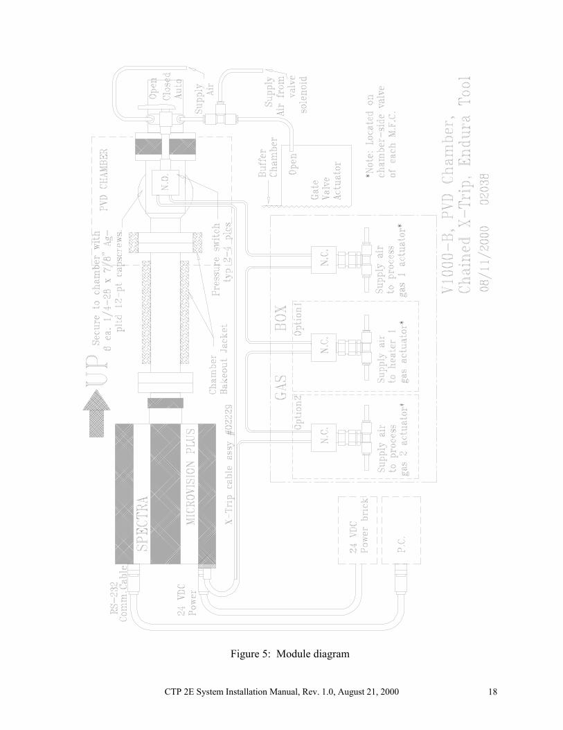
Primary filament control is provided through the state-engine design of the CTP 2E system control software, which relies upon the tool state information it obtains via the Endura RGA SECS port. This module employs a hardware backup for filament protection that activates whenever the chamber Gate Valve is closed. This turns off the filament when there is a chance that the chamber might be vented. An electrical “open” in the X-Trip circuit turns off the filament. When the Gate Valve is opened again, the filament can turn back on. As shown in Figure 5, a pressure sensitive switch is connected to the pneumatic “open” control line of the chamber Gate Valve using a tee fitting. The electrical cable from the switch is tied directly to the X-Trip jack on the back of the MicroVision Plus controller. Additionally, the inlet isolation valve is pneumatically actuated with the chamber Gate Valve. In the “auto” position, it opens and closes with the Gate Valve. Manual “Open” and “Close” positions of the inlet tee valve permit servicing the sensor without interrupting the tool chamber vacuum.
CTP 2E System Installation Manual, Rev. 1.0, August 21, 2000 18
Figure 5: Module diagram
CTP 2E System Installation Manual, Rev. 1.0, August 21, 2000 19
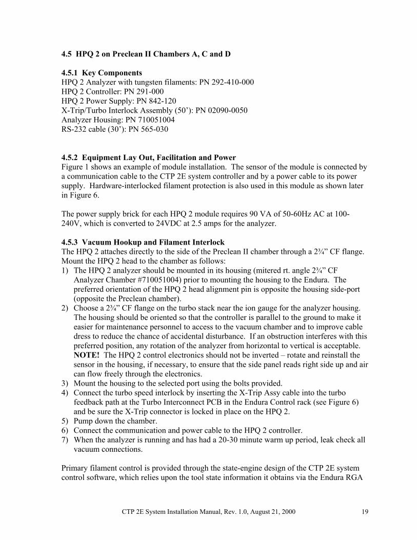
4.5 HPQ 2 on Preclean II Chambers A, C and D 4.5.1 Key Components HPQ 2 Analyzer with tungsten filaments: PN 292-410-000 HPQ 2 Controller: PN 291-000 HPQ 2 Power Supply: PN 842-120 X-Trip/Turbo Interlock Assembly (50’): PN 02090-0050 Analyzer Housing: PN 710051004 RS-232 cable (30’): PN 565-030 4.5.2 Equipment Lay Out, Facilitation and Power Figure 1 shows an example of module installation. The sensor of the module is connected by a communication cable to the CTP 2E system controller and by a power cable to its power supply. Hardware-interlocked filament protection is also used in this module as shown later in Figure 6. The power supply brick for each HPQ 2 module requires 90 VA of 50-60Hz AC at 100-240V, which is converted to 24VDC at 2.5 amps for the analyzer. 4.5.3 Vacuum Hookup and Filament Interlock The HPQ 2 attaches directly to the side of the Preclean II chamber through a 2¾” CF flange. Mount the HPQ 2 head to the chamber as follows: 1) The HPQ 2 analyzer should be mounted in its housing (mitered rt. angle 2¾” CF
Analyzer Chamber #710051004) prior to mounting the housing to the Endura. The preferred orientation of the HPQ 2 head alignment pin is opposite the housing side-port (opposite the Preclean chamber).
2) Choose a 2¾” CF flange on the turbo stack near the ion gauge for the analyzer housing. The housing should be oriented so that the controller is parallel to the ground to make it easier for maintenance personnel to access to the vacuum chamber and to improve cable dress to reduce the chance of accidental disturbance. If an obstruction interferes with this preferred position, any rotation of the analyzer from horizontal to vertical is acceptable. NOTE! The HPQ 2 control electronics should not be inverted – rotate and reinstall the sensor in the housing, if necessary, to ensure that the side panel reads right side up and air can flow freely through the electronics.
3) Mount the housing to the selected port using the bolts provided. 4) Connect the turbo speed interlock by inserting the X-Trip Assy cable into the turbo
feedback path at the Turbo Interconnect PCB in the Endura Control rack (see Figure 6) and be sure the X-Trip connector is locked in place on the HPQ 2.
5) Pump down the chamber. 6) Connect the communication and power cable to the HPQ 2 controller. 7) When the analyzer is running and has had a 20-30 minute warm up period, leak check all
vacuum connections. Primary filament control is provided through the state-engine design of the CTP 2E system control software, which relies upon the tool state information it obtains via the Endura RGA

CTP 2E System Installation Manual, Rev. 1.0, August 21, 2000 20
SECS port. This module employs a hardware backup for filament protection that activates whenever the chamber turbo pump is not at full speed. This turns off the filament when there is a chance that the chamber might be vented or at elevated pressure. An electrical “open” in the X-Trip circuit turns off the filament. When the chamber turbo pump attains full speed again, the filament can turn back on. As shown in Figure 6, an optically isolated current sensor is inserted into the pump-speed feedback loop at the back of the Endura turbo controller where it connects to the PC board. An electrical cable from the sensor ties back to the X-Trip jack on the back of the HPQ 2 controller.
CTP 2E System Installation Manual, Rev. 1.0, August 21, 2000 21
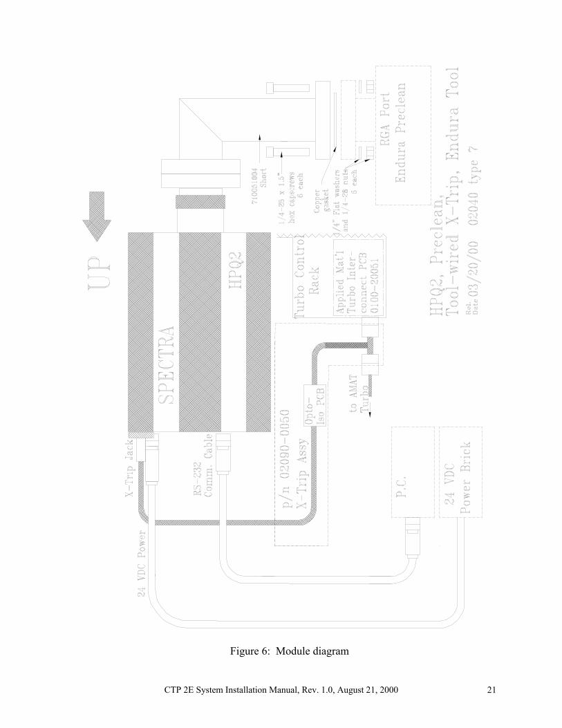
Figure 6: Module diagram
CTP 2E System Installation Manual, Rev. 1.0, August 21, 2000 22
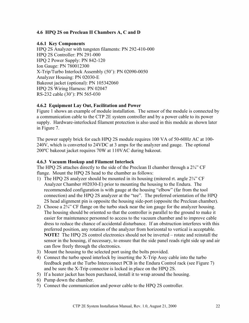
4.6 HPQ 2S on Preclean II Chambers A, C and D 4.6.1 Key Components HPQ 2S Analyzer with tungsten filaments: PN 292-410-000 HPQ 2S Controller: PN 291-000 HPQ 2 Power Supply: PN 842-120 Ion Gauge: PN 780012300 X-Trip/Turbo Interlock Assembly (50’): PN 02090-0050 Analyzer Housing: PN 02030-E Bakeout jacket (optional): PN 105342060 HPQ 2S Wiring Harness: PN 02047 RS-232 cable (30’): PN 565-030 4.6.2 Equipment Lay Out, Facilitation and Power Figure 1 shows an example of module installation. The sensor of the module is connected by a communication cable to the CTP 2E system controller and by a power cable to its power supply. Hardware-interlocked filament protection is also used in this module as shown later in Figure 7. The power supply brick for each HPQ 2S module requires 100 VA of 50-60Hz AC at 100-240V, which is converted to 24VDC at 3 amps for the analyzer and gauge. The optional 200ºC bakeout jacket requires 70W at 110VAC during bakeout. 4.6.3 Vacuum Hookup and Filament Interlock The HPQ 2S attaches directly to the side of the Preclean II chamber through a 2¾” CF flange. Mount the HPQ 2S head to the chamber as follows: 1) The HPQ 2S analyzer should be mounted in its housing (mitered rt. angle 2¾” CF
Analyzer Chamber #02030-E) prior to mounting the housing to the Endura. The recommended configuration is with gauge at the housing “elbow” (far from the tool connection) and the HPQ 2S analyzer at the “tee”. The preferred orientation of the HPQ 2S head alignment pin is opposite the housing side-port (opposite the Preclean chamber).
2) Choose a 2¾” CF flange on the turbo stack near the ion gauge for the analyzer housing. The housing should be oriented so that the controller is parallel to the ground to make it easier for maintenance personnel to access to the vacuum chamber and to improve cable dress to reduce the chance of accidental disturbance. If an obstruction interferes with this preferred position, any rotation of the analyzer from horizontal to vertical is acceptable. NOTE! The HPQ 2S control electronics should not be inverted – rotate and reinstall the sensor in the housing, if necessary, to ensure that the side panel reads right side up and air can flow freely through the electronics.
3) Mount the housing to the selected port using the bolts provided. 4) Connect the turbo speed interlock by inserting the X-Trip Assy cable into the turbo
feedback path at the Turbo Interconnect PCB in the Endura Control rack (see Figure 7) and be sure the X-Trip connector is locked in place on the HPQ 2S.
5) If a heater jacket has been purchased, install it to wrap around the housing. 6) Pump down the chamber. 7) Connect the communication and power cable to the HPQ 2S controller.

CTP 2E System Installation Manual, Rev. 1.0, August 21, 2000 23
8) When the analyzer is running and has had a 20-30 minute warm up period, leak check all vacuum connections.
If the optional bakeout heater jacket has been purchased and installed, it can be plugged into an AC extension cord when baking is required. Baking is not recommended at any time other than after installation. Note that bakeout times of ONLY two to eight hours are recommended depending upon how clean the analyzer and housing were initially and the ultimate vacuum background desired. Note that the sensor will not give good data while baking. Do NOT leave the jacket on all the time. Primary filament control is provided through the state-engine design of the CTP 2E system control software, which relies upon the tool state information it obtains via the Endura RGA SECS port. This module employs a hardware backup for filament protection that activates whenever the chamber turbo pump is not at full speed. This turns off the filament when there is a chance that the chamber might be vented or at elevated pressure. An electrical “open” in the X-Trip circuit turns off the filament. When the chamber turbo pump attains full speed again, the filament can turn back on. As shown in Figure 7, an optically isolated current sensor is inserted into the pump-speed feedback loop at the back of the Endura turbo controller where it connects to the PC board. An electrical cable from the sensor ties back to the X-Trip jack on the back of the HPQ 2S controller. The ion gauge filament is also protected.
CTP 2E System Installation Manual, Rev. 1.0, August 21, 2000 24
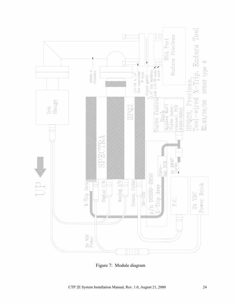
Figure 7: Module diagram