Embed Size (px)
Citation preview

CTI 2501
EIGHT CHANNEL ANALOG INPUT /
FOUR CHANNEL ANALOG OUTPUT MODULE
INSTALLATION AND OPERATION GUIDE Version 1.0
CTI Part # 062-00341-010
2501IOG 091205 $25


CTI 2501 Installation and Operation Guide iii
Copyright © 2002-2014 Control Technology Inc.
All rights reserved.
This manual is published by Control Technology Inc., 5734 Middlebrook Pike, Knoxville, TN
37921. This manual contains references to brand and product names which are tradenames,
trademarks, and/or registered trademarks of Control Technology Inc. and Siemens AG. Siemens®
and SIMATIC® are registered trademarks of Siemens AG. Other references to brand and product
names are tradenames, trademarks, and/or registered trademarks of their respective holders.
DOCUMENT DISCLAIMER STATEMENT
Every effort has been made to ensure the accuracy of this document; however, errors do occasionally
occur. CTI provides this document on an "as is" basis and assumes no responsibility for direct or
consequential damages resulting from the use of this document. This document is provided without
express or implied warranty of any kind, including but not limited to the warranties of
merchantability or fitness for a particular purpose. This document and the products it references are
subject to change without notice. If you have a comment or discover an error, please call us toll-free
at 1-800-537-8398.
REVISION HISTORY
Version 1.0 2/01/02 Original Release
1/12/09 Added note that CN5 jumper must be installed for Rev F board
4/08/14 Added 4WX/4WY login

CTI 2501 Installation and Operation Guide v
PREFACE
This Installation and Operation Guide provides installation and operation instructions for the CTI
2501 8 Analog Input / 4 Analog Output Module for Simatic 505 programmable controllers. We
assume you are familiar with the operation of Simatic 505 programmable controllers. Refer to the
appropriate user documentation for specific information on the Simatic 505 programmable
controllers and I/O modules.
This Installation and Operation Guide is organized as follows:
Chapter 1 provides a description of the module.
Chapter 2 covers installation and wiring.
Chapter 3 is a guide to troubleshooting.
Appendix A details compatibility between the 2501 and the Siemens 505-7012 and 505-7016.
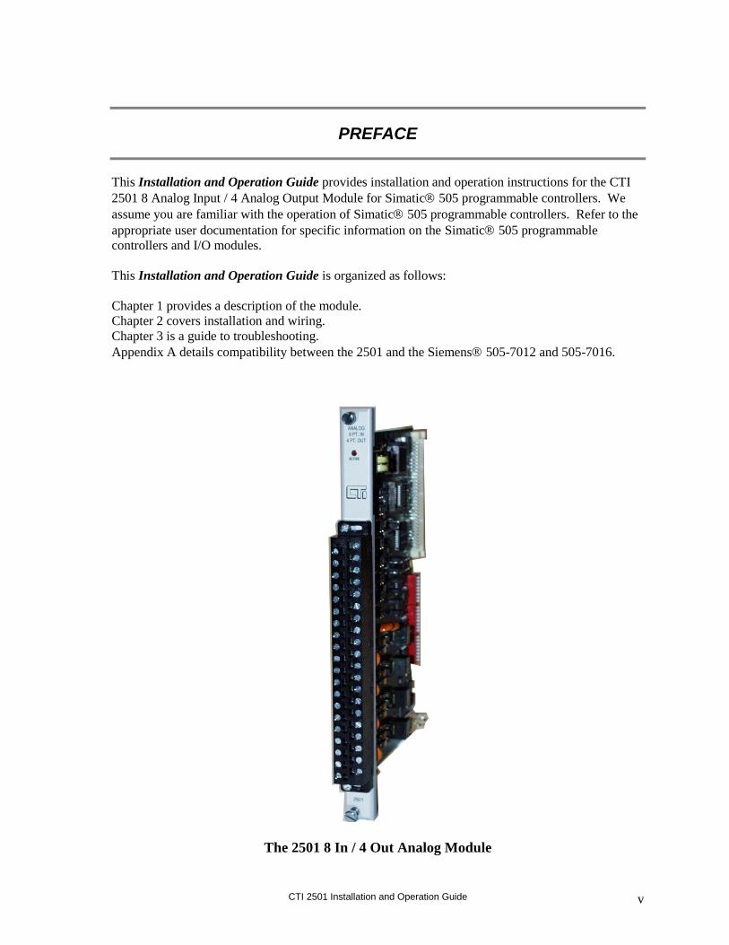
The 2501 8 In / 4 Out Analog Module

CTI 2501 Installation and Operation Guide vii
USAGE CONVENTIONS
NOTE:
Notes alert the user to special features or procedures.
CAUTION:
Cautions alert the user to procedures that could damage equipment.
WARNING:
Warnings alert the user to procedures that could damage equipment and endanger the user.


CTI 2501 Installation and Operation Guide ix
TABLE OF CONTENTS
PREFACE ........................................................................................................................................................... V
USAGE CONVENTIONS .............................................................................................................................. VII
TABLE OF CONTENTS ................................................................................................................................. IX
1. OVERVIEW .................................................................................................................................................... 1
1.0. Product Summary ................................................................................................................................. 1 1.1. Front Panel Description ....................................................................................................................... 1 1.2. Asynchronous Operation ...................................................................................................................... 2 1.3. Immediate I/O ....................................................................................................................................... 2 1.4. Unipolar or Bipolar Mode .................................................................................................................... 2 1.5. Voltage or Current Input / Output ........................................................................................................ 2 1.6. Using an Input with 20% Offset............................................................................................................ 3 1.7. Using the Module with the 20% Offset Input Scaling ........................................................................... 3 1.8. Digital Input Word Map ....................................................................................................................... 3 1.9. Analog to Digital Input Conversions .................................................................................................... 4 1.10. Effect of Out-of-Range Input Signals .................................................................................................. 4 1.11. Input Resolution .................................................................................................................................. 7 1.12. Output Signal Description .................................................................................................................. 8 1.13. Digital to Analog Conversion: Output................................................................................................ 9 1.14. Resolution: Output .............................................................................................................................. 9 1.15. Using the Module with a Built-In 20% Offset Output Calculation ................................................... 10
CHAPTER 2. INSTALLATION ...................................................................................................................... 11
2.1. Planning the Installation ................................................................................................................... 11 2.2. Unpacking the Module........................................................................................................................ 14 2.3. Configuring the Module ...................................................................................................................... 15 2.4. Inserting the Module into the I/O Base ............................................................................................... 22 2.5. Wiring the Output Connector ............................................................................................................. 22 2.6. Inserting the Screw Terminal Connector ............................................................................................ 24 2.7. Connecting the 24VDC User Power Supply ....................................................................................... 24 2.8. Checking Module Operation............................................................................................................... 24 2.9. Power Cycling .................................................................................................................................... 27
CHAPTER 3. TROUBLESHOOTING ........................................................................................................... 28
SPECIFICATIONS ........................................................................................................................................... 31
APPENDIX A. COMPATIBILITY WITH SIEMENS 505-7012/7016 ..................................................... 33
APPENDIX B. JUMPER SETTINGS LOG SHEET ..................................................................................... 35
LIMITED PRODUCT WARRANTY ............................................................................................................. 37
REPAIR POLICY ............................................................................................................................................. 38
CTI 2501 Installation and Operation Guide 1
1. OVERVIEW
1.0. Product Summary
The CTI 2501 Eight Channel Analog Input / Four Channel Analog Output Module is a member of
Control Technology's family of I/O modules compatible with the Simatic 505 programmable
controllers. The 2501 is designed to translate a digital word from the programmable controller (PLC)
into an equivalent analog voltage and current signal, and to translate an analog input signal into an
equivalent digital word which is then sent to the programmable controller.
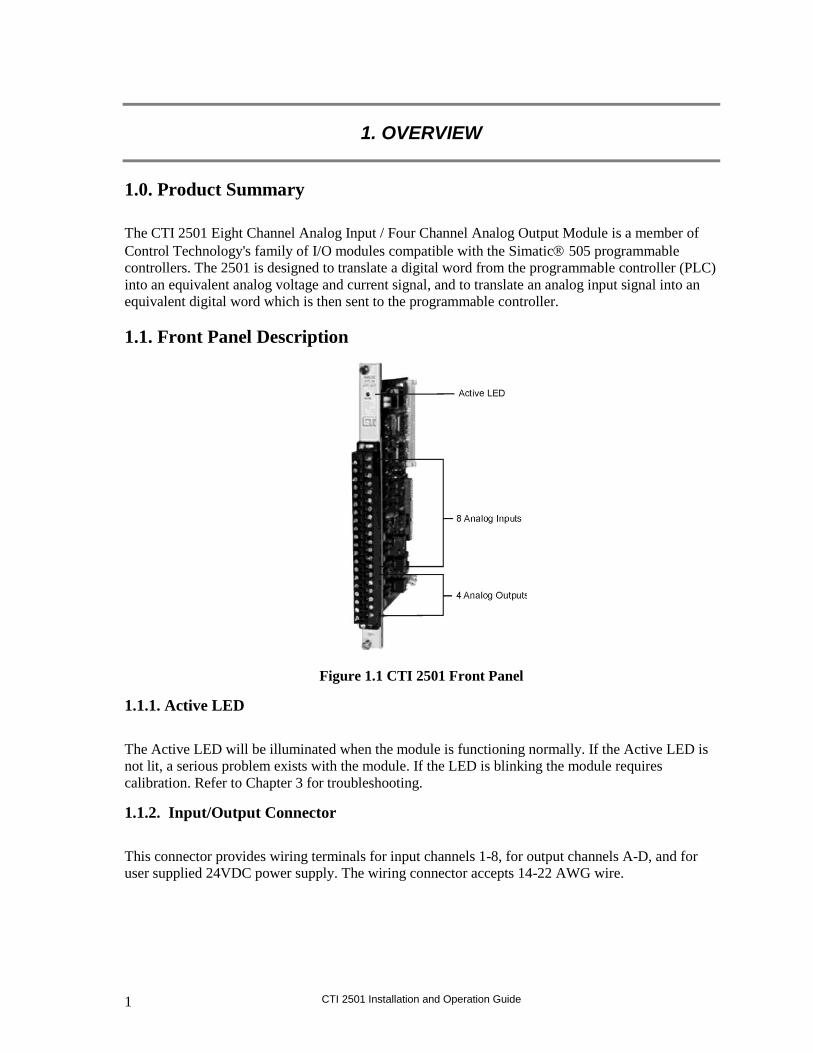
1.1. Front Panel Description
Figure 1.1 CTI 2501 Front Panel
1.1.1. Active LED
The Active LED will be illuminated when the module is functioning normally. If the Active LED is
not lit, a serious problem exists with the module. If the LED is blinking the module requires
calibration. Refer to Chapter 3 for troubleshooting.
1.1.2. Input/Output Connector
This connector provides wiring terminals for input channels 1-8, for output channels A-D, and for
user supplied 24VDC power supply. The wiring connector accepts 14-22 AWG wire.

CTI 2501 Installation and Operation Guide 2
1.2. Asynchronous Operation
The module operates asynchronously with respect to the PLC so that a scan of the PLC and a module
input or output scan cycle do not occur at the same time. For inputs, the module will translate all
analog inputs in one module update and store the translated words in buffer memory. The PLC
retrieves the stored words from the module buffer memory at the start of the I/O scan. For the output,
the signal change is dependent on the update time of the module. The following figure illustrates this
relationship:
Figure 1.2 Relation of Update Time Change in Signal Output
1.3. Immediate I/O
The 2501 Analog Output Module is fully compatible with the Immediate output instructions for the
545 and 555 PLCs.
1.4. Unipolar or Bipolar Mode
Each input or output channel may be configured to provide either a bipolar or unipolar input/output
signal. Selection of unipolar/bipolar mode is made via a jumper and dip switches (see Section 2.3).
1.5. Voltage or Current Input / Output
Each of the module’s eight input channels may be configured to receive either voltage or current
analog signals. For unipolar input signals, the range is 0 to 5VDC, 0 to 10VDC or 0 to +20mA. For
bipolar input signals, the signal range is –5 to +5VDC, -10 to +10VDC or –20 to +20mA. Selection
of voltage or current mode and voltage range are made via internal jumpers and dip switches (see
Section 2.3).
Voltage and current output signals are both available simultaneously. For Unipolar output signals the
ranges supported are 0 to 5VDC, 0 to 10VDC, and 0 to 20mA. For Bipolar outputs the ranges

CTI 2501 Installation and Operation Guide 3
supported are -5 to +5VDC, -10 to +10VDC, and -20 to +20mA. Selection of voltage ranges and
Unipolar and Bipolar operation are made via internal jumpers and DIP switches (see Section 2.3).
1.6. Using an Input with 20% Offset
Some applications use transducers that provide 1 to 5 volts (4 to 20mA) input signals instead of 0 to
5 volt (0 to 20mA) input signals. You can allow for this 20% offset by including some additional
instructions in your RLL (Relay Ladder Logic) program.
First, subtract 6400 from the input data word (WX). Then, multiply the result by 125 and divide the
product by 100. This yields the following equation:
(WX –6400) x 125 100 = 20% offset data word
Consult your PLC programming manual (or program design guide) for information about RLL
instructions used in the conversion.
1.7. Using the Module with the 20% Offset Input Scaling
If all eight inputs are used in offset mode the 2501 may be configured to perform the offset
calculation automatically (see Section 2.3.4). Jumper JP1 when enabled will configure the module
such that all inputs will be scaled for 1-5VDC or 4-20mA operation.
1.8. Digital Input Word Map
An analog input signal is translated into a 15-bit plus sign digital word. Since the PLC requires a 15-
bit input word, the 15-bit plus sign value from the converter is placed into a 16-bit word for
transmittal to the PLC.
Figure 1.3 Word Input to the PLC from the Module

CTI 2501 Installation and Operation Guide 4
1.9. Analog to Digital Input Conversions
1.9.1. Unipolar Mode Conversion
The following equations may be used to calculate the digital word which will result from a particular
voltage or current input in the Unipolar Input Mode:
0 to 5VDC range Digital Word (WX) = (Input voltage x 32000) 5 volts
example: to generate an input voltage of 2.5VDC, the WX value input to the
PLC is calculated as follows: WX = (2.5 x 32000) 5 = 16000
0 to 10VDC range Digital Word (WX) = (Input voltage x 32000) 10 volts
example: 7.5VDC input
WX = (7.5 x 32000) 10 = 24000
0 to 20mA range Digital Word (WX) = (Input current x 32000) 20mA
example: 10mA input
WX = (10 x 32000) 20 = 16000
1.9.2. Bipolar Mode Conversion
The following equations may be used to calculate the digital word which will result from a particular
voltage or current input in the Bipolar Input Mode:
-5 to +5VDC range Digital Word (WX) = (Input voltage x 32000) 5 volts
example: to generate an input voltage of -2.5VDC, the WX value input from
the PLC is calculated as follows: WX = (-2.5 x 32000) 5 = -16000
-10 to +10VDC range Digital Word (WX) = (Input voltage x 32000) 10 volts
example: 10VDC input
WX = (10 x 32000) 10 = 32000
-20 to +20mA range Digital Word (WX) = (Input current x 32000) 20mA
example: -15mA input
WX = (-15 x 32000) 20 = -24000
1.10. Effect of Out-of-Range Input Signals
The 2501 utilizes the underrange and overrange codes of 32758 and 32759, respectively, to indicate
when a channel has reached individual limits. The value of the underrange or overrange condition
varies from channel to channel. The reason for this is that as a channel is calibrated, all of the gains
and offsets and dynamic ranges of the analog to digital converter of the system are compensated for
in each analog input channel. Therefore, the point at which the analog to digital converter reaches a
saturation point and can no longer produce a change in counts for corresponding change in input
signal is called the overrange or underrange limit of the channel. This level may be different for

CTI 2501 Installation and Operation Guide 5
every channel. In Figures 1.4 and 1.7, the limits for the overrange and underrange values are the
minimum limits for a given channel. The actual limits for an individual channel may be greater.
NOTE:
+32750 is the last valid reported value before an overrange or overflow error is reported.
1.10.1. Unipolar Mode
Signals falling below the lower limits in 0 to 5V Input Mode or 0 to 10V Input Mode are translated
into a digital word that outputs a specific code to indicate an overrange or underrange condition. The
underrange capability of any channel in Unipolar Mode may produce a negative value to the PLC for
a number of counts before the underrange code is produced.
Figure 1.4 Voltage Input Limits (Unipolar)
Figures 1.5 and 1.6 show the binary values of typical overrange and underrange conditions for
Unipolar mode.
Figure 1.5 Overrange Word Value (Unipolar)

CTI 2501 Installation and Operation Guide 6
Figure 1.6 Underrange Word Value (Unipolar)
1.10.2. Bipolar Mode
In Bipolar Mode signals above or below the upper and lower limits in the -5 to +5VDC or -10 to
+10VDC range are translated to a digital word and also utilize the overrange and underrange values.
The actual limit for each channel will vary from channel to channel as described in the previous
section.
Figure 1.7 Voltage Input Limits (Bipolar)
Figures 1.8 and 1.9 show the binary values of typical overrange and underrange conditions for
Bipolar Mode.
Figure 1.8 Overrange Word Value (Bipolar)
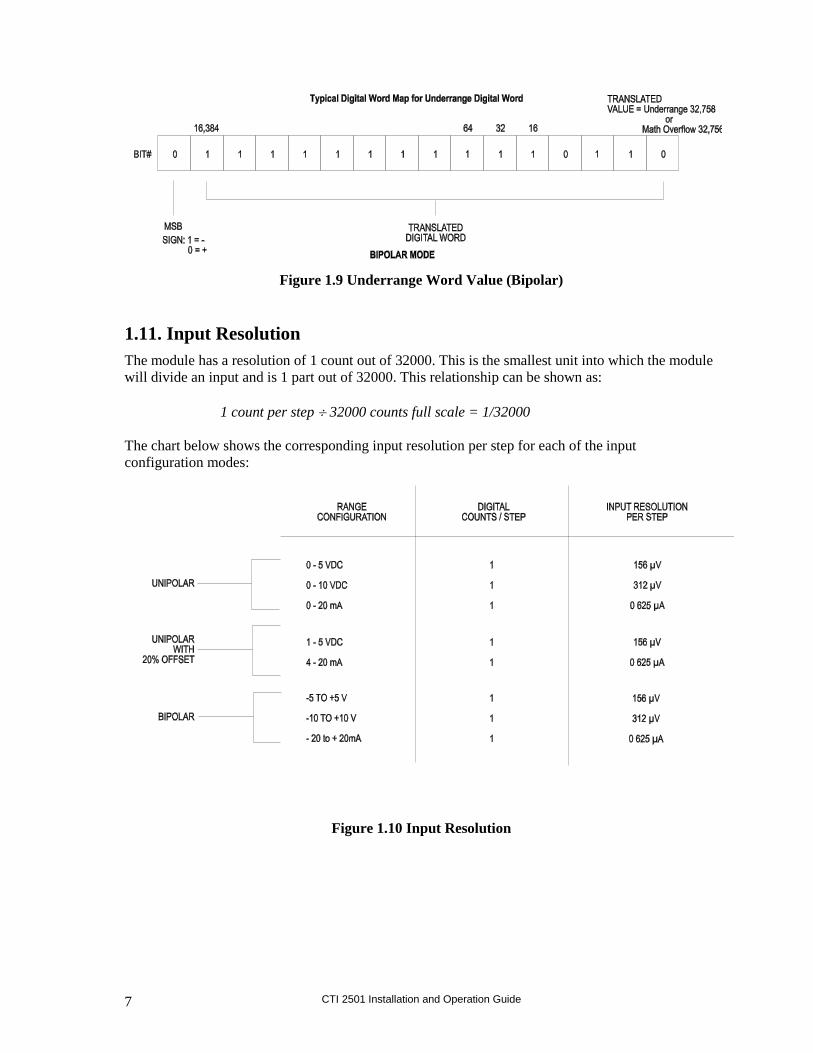
CTI 2501 Installation and Operation Guide 7
Figure 1.9 Underrange Word Value (Bipolar)
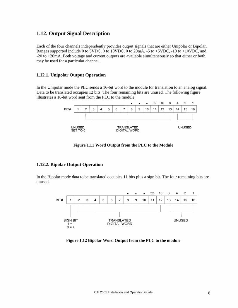
1.11. Input Resolution
The module has a resolution of 1 count out of 32000. This is the smallest unit into which the module
will divide an input and is 1 part out of 32000. This relationship can be shown as:
1 count per step 32000 counts full scale = 1/32000
The chart below shows the corresponding input resolution per step for each of the input
configuration modes:
Figure 1.10 Input Resolution
CTI 2501 Installation and Operation Guide 8
1.12. Output Signal Description
Each of the four channels independently provides output signals that are either Unipolar or Bipolar.
Ranges supported include 0 to 5VDC, 0 to 10VDC, 0 to 20mA, -5 to +5VDC, -10 to +10VDC, and
-20 to +20mA. Both voltage and current outputs are available simultaneously so that either or both
may be used for a particular channel.
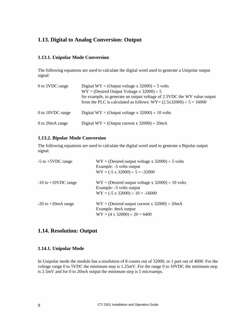
1.12.1. Unipolar Output Operation
In the Unipolar mode the PLC sends a 16-bit word to the module for translation to an analog signal.
Data to be translated occupies 12 bits. The four remaining bits are unused. The following figure
illustrates a 16-bit word sent from the PLC to the module.
Figure 1.11 Word Output from the PLC to the Module
1.12.2. Bipolar Output Operation
In the Bipolar mode data to be translated occupies 11 bits plus a sign bit. The four remaining bits are
unused.
Figure 1.12 Bipolar Word Output from the PLC to the module
CTI 2501 Installation and Operation Guide 9
1.13. Digital to Analog Conversion: Output
1.13.1. Unipolar Mode Conversion
The following equations are used to calculate the digital word used to generate a Unipolar output
signal:
0 to 5VDC range Digital WY = (Output voltage x 32000) 5 volts
WY = (Desired Output Voltage x 32000) 5
for example, to generate an output voltage of 2.5VDC the WY value output
from the PLC is calculated as follows: WY= (2.5x32000) 5 = 16000
0 to 10VDC range Digital WY = (Output voltage x 32000) 10 volts
0 to 20mA range Digital WY = (Output current x 32000) 20mA
1.13.2. Bipolar Mode Conversion
The following equations are used to calculate the digital word used to generate a Bipolar output
signal.
-5 to +5VDC range WY = (Desired output voltage x 32000) 5 volts
Example: -5 volts output
WY = (-5 x 32000) 5 = -32000
-10 to +10VDC range WY = (Desired output voltage x 32000) 10 volts
Example: -5 volts output
WY = (-5 x 32000) 10 = -16000
-20 to +20mA range WY = (Desired output current x 32000) 20mA
Example: 4mA output
WY = (4 x 32000) 20 = 6400
1.14. Resolution: Output
1.14.1. Unipolar Mode
In Unipolar mode the module has a resolution of 8 counts out of 32000, or 1 part out of 4000. For the
voltage range 0 to 5VDC the minimum step is 1.25mV. For the range 0 to 10VDC the minimum step
is 2.5mV and for 0 to 20mA output the minimum step is 5 microamps.
CTI 2501 Installation and Operation Guide 10
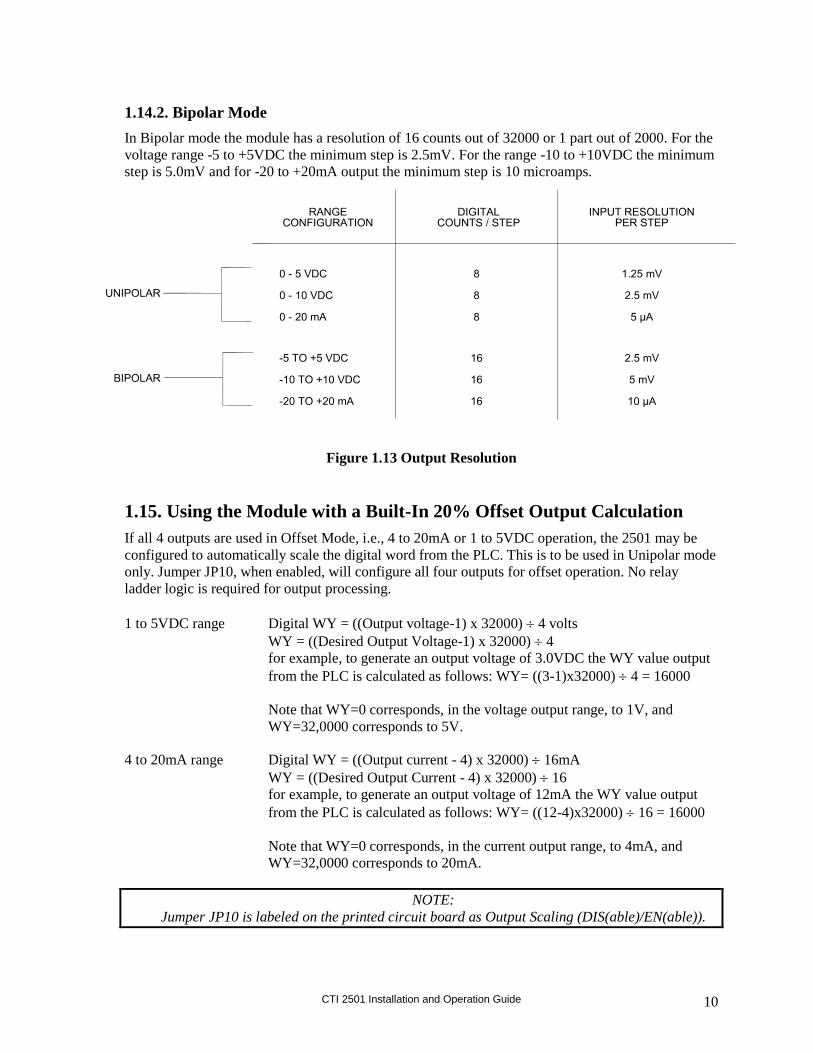
1.14.2. Bipolar Mode
In Bipolar mode the module has a resolution of 16 counts out of 32000 or 1 part out of 2000. For the
voltage range -5 to +5VDC the minimum step is 2.5mV. For the range -10 to +10VDC the minimum
step is 5.0mV and for -20 to +20mA output the minimum step is 10 microamps.
Figure 1.13 Output Resolution
1.15. Using the Module with a Built-In 20% Offset Output Calculation
If all 4 outputs are used in Offset Mode, i.e., 4 to 20mA or 1 to 5VDC operation, the 2501 may be
configured to automatically scale the digital word from the PLC. This is to be used in Unipolar mode
only. Jumper JP10, when enabled, will configure all four outputs for offset operation. No relay
ladder logic is required for output processing.
1 to 5VDC range Digital WY = ((Output voltage-1) x 32000) 4 volts
WY = ((Desired Output Voltage-1) x 32000) 4
for example, to generate an output voltage of 3.0VDC the WY value output
from the PLC is calculated as follows: WY= ((3-1)x32000) 4 = 16000
Note that WY=0 corresponds, in the voltage output range, to 1V, and
WY=32,0000 corresponds to 5V.
4 to 20mA range Digital WY = ((Output current - 4) x 32000) 16mA
WY = ((Desired Output Current - 4) x 32000) 16
for example, to generate an output voltage of 12mA the WY value output
from the PLC is calculated as follows: WY= ((12-4)x32000) 16 = 16000
Note that WY=0 corresponds, in the current output range, to 4mA, and
WY=32,0000 corresponds to 20mA.
NOTE:
Jumper JP10 is labeled on the printed circuit board as Output Scaling (DIS(able)/EN(able)).

CTI 2501 Installation and Operation Guide 11
CHAPTER 2. INSTALLATION
The installation of the 2501 Eight Channel Analog Input / Four Channel Output Module involves the
following steps:
1. Planning the installation
2. Configuring the module
3. Inserting the module into the I/O base
4. Wiring the module output screw terminal connector
5. Connecting the 24VDC user power supply
6. Checking module operation.
The steps listed above are explained in detail in the following pages.
2.1. Planning the Installation
Planning is the first step in the installation of the module. This involves:
1. Calculating the I/O base power budget
2. Selecting a proper user power supply and wiring
3. Routing the wiring to minimize noise, and
4. Selecting the proper wiring method for the type of output you will use.
The following sections discuss these important considerations of the installation.
2.1.1. Calculating the I/O Base Power Budget
The 2501 requires 3.0 watts (maximum) of +5VDC power from the I/O base. Before inserting the
module into the I/O base, ensure that the base power supply capacity is not exceeded.
2.1.2. Choosing a Power Supply
The power supply should be a single voltage, 20-28VDC nominal 2.0 amp, UL Class 2 device. The
compliance of the output circuits is directly related to the output voltage. The drive voltage and
current are specified at 24VDC.

CTI 2501 Installation and Operation Guide 12
2.1.3. Wiring Consideration
The module requires separate wiring for the power supply and for the input and output signals.
Power and signal wiring must be separated to prevent noise in the signal wiring. Input and output
signal wiring must be shielded, twisted-pair cable, with 14 to 22 gauge stranded conductors. A
twisted pair will aid in the rejection of conducted and radiated interference from other energy
sources. The cable shield should always be terminated to earth ground at the I/O base. It should not
be terminated at the output connector. Use the following guidelines when wiring the module:
Always use the shortest possible cables
Avoid placing power supply wires and signal wires near sources of high energy
Avoid placing low voltage wire parallel to high energy wire (if the two wires must meet, cross
them at a right angle)
Avoid bending the wires into sharp angles
Use wireways for wire routing
Be sure to provide a proper earth ground for the cable shield at the I/O base
Avoid placing wires on any vibrating surfaces
2.1.4. Requirements for Signal Wire Carrying Current
You must calculate the loop wiring resistance for any current output circuits. The loop resistance is
determined by the length and type of wire, as well as the field device series resistance.
The circuit resistance must not exceed 1000 ohms. If a separate 20 volt power supply is used in the
loop, the minimum resistance increases 1000 ohms, and the maximum resistance becomes 2000
ohms. Any value over 1000 ohms prevents the module from operating accurately. The following
figure provides a schematic for wiring a loop with a resistance of less than 1000 ohms. It also shows
a schematic for adding a power supply to allow loop resistance up to 2000 ohms. Use the following
equation to determine the resistance of an output loop for a channel:
Resistance = (2 x CL x RFT) + TFL
where: CL is the cable length
RFT is the conductor resistance (ohms/unit length)
TFL is the resistance of the field device

CTI 2501 Installation and Operation Guide 13
Figure 2.1 Current Output Circuits
2.1.5. Requirements for Signal Wire Providing Voltage
Applications using voltage signals require some special considerations to ensure the module’s
accuracy. Two additional parameters must be considered:
Resistive load of the field device
Capacitance of the cable wiring
The resistive load of the field device must be no lower than 1K ohms. The cable capacitance must be
less than 0.01 microfarad.
The cable capacitance is a function of the cable length. To determine the maximum cable length
allowed, find the nominal value of cable capacitance per unit length as given by the manufacturer.
Use this value in the following equation to determine the maximum cable length:
Nominal Cable Capacitance (per unit length) = (0.01 microfarads) (Maximum Cable Length)
NOTE:
Nominal capacitance is measured between the conductors. However, if one
conductor is connected to the shield via a grounded power supply, then the nominal
value will usually double in value.
CTI 2501 Installation and Operation Guide 14
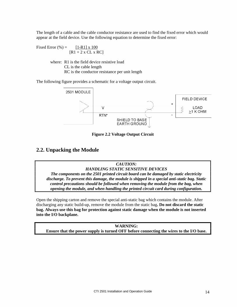
The length of a cable and the cable conductor resistance are used to find the fixed error which would
appear at the field device. Use the following equation to determine the fixed error:
Fixed Error (%) = [1-R1] x 100
[R1 + 2 x CL x RC]
where: R1 is the field device resistive load
CL is the cable length
RC is the conductor resistance per unit length
The following figure provides a schematic for a voltage output circuit.
Figure 2.2 Voltage Output Circuit
2.2. Unpacking the Module
CAUTION:
HANDLING STATIC SENSITIVE DEVICES
The components on the 2501 printed circuit board can be damaged by static electricity
discharge. To prevent this damage, the module is shipped in a special anti-static bag. Static
control precautions should be followed when removing the module from the bag, when
opening the module, and when handling the printed circuit card during configuration.
Open the shipping carton and remove the special anti-static bag which contains the module. After
discharging any static build-up, remove the module from the static bag. Do not discard the static
bag. Always use this bag for protection against static damage when the module is not inserted
into the I/O backplane.
WARNING:
Ensure that the power supply is turned OFF before connecting the wires to the I/O base.
CTI 2501 Installation and Operation Guide 15
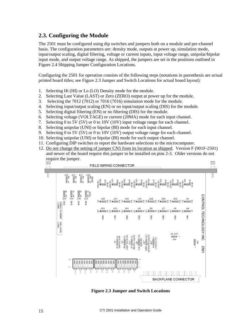
2.3. Configuring the Module
The 2501 must be configured using dip switches and jumpers both on a module and per-channel
basis. The configuration parameters are: density mode, outputs at power up, simulation mode,
input/output scaling, digital filtering, voltage or current inputs, input voltage range, unipolar/bipolar
input mode, and output voltage range. As shipped, the jumpers are set in the positions outlined in
Figure 2.4 Shipping Jumper Configuration Locations.
Configuring the 2501 for operation consists of the following steps (notations in parenthesis are actual
printed board titles; see Figure 2.3 Jumper and Switch Locations for actual board layout):
1. Selecting Hi (HI) or Lo (LO) Density mode for the module.
2. Selecting Last Value (LAST) or Zero (ZERO) output at power up for the module.
3. Selecting the 7012 (7012) or 7016 (7016) simulation mode for the module.
4. Selecting input/output scaling (EN) or no input/output scaling (DIS) for the module.
5. Selecting digital filtering (EN) or no filtering (DIS) for the module.
6. Selecting voltage (VOLTAGE) or current (20MA) mode for each input channel.
7. Selecting 0 to 5V (5V) or 0 to 10V (10V) input voltage range for each channel.
8. Selecting unipolar (UNI) or bipolar (BI) mode for each input channel.
9. Selecting 0 to 5V (5V) or 0 to 10V (10V) output voltage range for each channel.
10. Selecting unipolar (UNI) or bipolar (BI) mode for each output channel.
11. Configuring DIP switches to report the hardware selections to the microcomputer.
12. Do not change the setting of jumper CN5 from its location as shipped. Version F (901F-2501)
and newer of the board require this jumper to be installed on pins 2-3. Older versions do not
require the jumper.
Figure 2.3 Jumper and Switch Locations

CTI 2501 Installation and Operation Guide 16
Channel
Number
Voltage
Current
Jumper
Jumper
Position V or 20mA
Voltage
Range
Jumper
Jumper
Position 5V or 10V
Unipolar/
Bipolar
Jumper
Jumper
Position Uni or Bi
1 JP14 20mA JP5 5V JP4 UNI
2 JP15 20mA JP22 5V JP6 UNI
3 JP16 20mA JP23 5V JP7 UNI
4 JP17 20mA JP24 5V JP8 UNI
5 JP18 20mA JP25 5V JP9 UNI
6 JP19 20mA JP26 5V JP11 UNI
7 JP20 20mA JP27 5V JP12 UNI
8 JP21 20mA JP28 5V JP13 UNI
A - - JP29 5V JP33 UNI
B - - JP30 5V JP34 UNI
C - - JP31 5V JP35 UNI
D - - JP32 5V JP36 UNI
All Channels
1-8 IN,
A-D OUT
Hi/Lo
Density Hi or Lo
Outputs at
Power Up Last or Zero
SIM
Mode 7012 or 7016
Output
Scaling Dis or En
Dig Fil/
Cal Mode Dis or En
Input
Scaling Dis or En
Jumper JP38 JP37 JP3 JP10 JP2 JP1
Jumper
Position
HI LAST 7012 DIS EN DIS
Figure 2.4 Shipping Jumper Configuration Locations
Figure 2.5 Error Code Definitions
Error Code Error Code Definition
32,759 Input Overrange
32,758 Input Underrange
32,757 Input Failure (Not Used on the 2501)
32,756 Input Conversion or Arithmetic Overflow
32,755 Output Overrange
32,754 Output Underrange
32,753 Output 24V Power Supply Failure

CTI 2501 Installation and Operation Guide 17
2.3.1. Selecting Density Mode and Simulation Mode
These two settings combine to select the module login style. Four different settings are possible as
shown below:
Module Login JP38 (HI/LO) Setting JP3 (7012/7016) Setting
12WX / 4WY HI 7012
20WX / 4WY HI 7016
8WX LO 7012
4WX / 4WY LO 7016
Descriptions for each mode are included below.
12WX / 4WY Login (HI density, 7012)
This is the shipping configuration for the module. In this mode it simulates the Siemens 7012
module as shown below in Figure 2.6. The module returns the input values for each of the eight
input channels in WX1 – WX8. If an input channel contains an error, the appropriate error code
from Figure 2.5 is returned instead. WX9 – WX12 contain an echo of the output data for channels
A-D (as sent by the PLC) or an error word from Figure 2.5 in the event of an error on an output.
Inputs Item
WX1 Channel 1 input data or error code
WX2 Channel 2 input data or error code
WX3 Channel 3 input data or error code
WX4 Channel 4 input data or error code
WX5 Channel 5 input data or error code
WX6 Channel 6 input data or error code
WX7 Channel 7 input data or error code
WX8 Channel 8 input data or error code
WX9 Channel A output data echo or error code
WX10 Channel B output data echo or error code
WX11 Channel C output data echo or error code
WX12 Channel D output data echo or error code
WY13 Channel A output data from PLC
WY14 Channel B output data from PLC
WY15 Channel C output data from PLC
WY16 Channel D output data from PLC
Figure 2.6 Word Mapping for Hi Density, 7012 Simulation
CTI 2501 Installation and Operation Guide 18
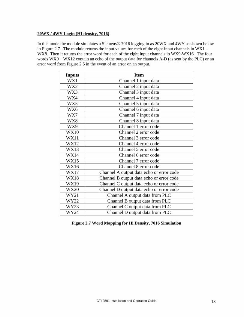
20WX / 4WY Login (HI density, 7016)
In this mode the module simulates a Siemens® 7016 logging in as 20WX and 4WY as shown below
in Figure 2.7. The module returns the input values for each of the eight input channels in WX1 –
WX8. Then it returns the error word for each of the eight input channels in WX9-WX16. The four
words WX9 – WX12 contain an echo of the output data for channels A-D (as sent by the PLC) or an
error word from Figure 2.5 in the event of an error on an output.
Inputs Item
WX1 Channel 1 input data
WX2 Channel 2 input data
WX3 Channel 3 input data
WX4 Channel 4 input data
WX5 Channel 5 input data
WX6 Channel 6 input data
WX7 Channel 7 input data
WX8 Channel 8 input data
WX9 Channel 1 error code
WX10 Channel 2 error code
WX11 Channel 3 error code
WX12 Channel 4 error code
WX13 Channel 5 error code
WX14 Channel 6 error code
WX15 Channel 7 error code
WX16 Channel 8 error code
WX17 Channel A output data echo or error code
WX18 Channel B output data echo or error code
WX19 Channel C output data echo or error code
WX20 Channel D output data echo or error code
WY21 Channel A output data from PLC
WY22 Channel B output data from PLC
WY23 Channel C output data from PLC
WY24 Channel D output data from PLC
Figure 2.7 Word Mapping for Hi Density, 7016 Simulation

CTI 2501 Installation and Operation Guide 19
8WX Login (LO density, 7012)
In this mode the module logs in as 8WX as shown below in Figure 2.8. The module returns the input
values for each of the eight input channels in WX1 – WX8. If an input channel contains an error, the
appropriate error code from Figure 2.5 is returned instead. The analog outputs are not driven and
remain at zero volts/amps out.
Inputs Item
WX1 Channel 1 input data or error code
WX2 Channel 2 input data or error code
WX3 Channel 3 input data or error code
WX4 Channel 4 input data or error code
WX5 Channel 5 input data or error code
WX6 Channel 6 input data or error code
WX7 Channel 7 input data or error code
WX8 Channel 8 input data or error code
Figure 2.8 Word Mapping for Lo Density, 7012 Simulation
4WX / 4WY Login (LO density, 7016)
NOTE: The 4WX/4WY login option is only supported on later revision of the 2501. To determine if your module
supports it:
1. Look at the pcb part number marked in white along the top of the board. It will be a number like “901F-
2501”. If your board is “901F-2501” or later (ie 901G-2501 is later), AND the white Revision marking at
the bottom of the board is “013” or greater, then the 4WX/4WY login is supported on your module.
2. If your board is 901F-2501 and the Revision is 011 or 012, then your board can be upgraded to include the
4WX/4WY login. Contact CTI for information about an upgrade.
3. Other versions of the 2501 cannot be upgraded to include this feature. Contact CTI for information about
exchanging your module for a newer version.
In this mode the module logs in as 4WX / 4WY as shown below in Figure 2.9. The module returns
the input values for the first four input channels in WX1 – WX4.
Inputs Item
WX1 Channel 1 input data or error code
WX2 Channel 2 input data or error code
WX3 Channel 3 input data or error code
WX4 Channel 4 input data or error code
WY5 Channel A output data from PLC
WY6 Channel B output data from PLC
WY7 Channel C output data from PLC
WY8 Channel D output data from PLC
Figure 2.6 Word Mapping for Hi Density, 7012 Simulation

CTI 2501 Installation and Operation Guide 20
2.3.2. Selecting Either Zero or Last Value Output at Power Up
Upon power up of the base power, the 2501 allows the user to choose between either a zero output
value or last output value when transitioning to the next update. A hardware JP37 jumper setting (see
Figure 2.3) sets the entire module for the mode chosen. The normal shipping configuration is in the
LAST VALUE mode.
2.3.3. Selecting Automatic Input/Output Scaling Mode
Some applications require an Offset Input/Output Scaling Mode for 4-20mA or 1-5VDC. The PLC
can adjust a loop calculation to provide an offset scaling input/output. If the application does not use
the PID control block then the processing must be done in relay ladder logic. The 2501 can perform
this offset calculation and input or output an offset signal independent of the PLC. Selecting this
function with JP1 (input) or JP10 (output) causes all inputs and outputs to be scaled. Move the
jumper to the ENABLED position to select this function. The normal shipping configuration is
DISABLED for both inputs and outputs.
2.3.4. Selecting Digital Filtering
Locate the Digital Filtering Jumper “DIG FIL/CAL MODE” JP2 (see Figure 2.3). To enable digital
filtering, set the jumper in the “EN” position; to disable, set to the “DIS” position. Since many
analog input signals contain noise, CTI recommends using digital filtering unless maximum response
time is required. The built-in digital filtering has a time constant of 0.3 seconds, meaning it reaches
63% of its final value in 0.3s and settles to within a high precision within 1.5 seconds.
As shipped, digital filtering is ENABLED for all 8 analog inputs.
2.3.5. Selecting Voltage or Current Input Mode
Locate the 8 Voltage/Current Jumpers corresponding to input channels 1 through 8 (see Figure 2.3
for the location of these jumpers). For each input channel, select current mode by placing the jumper
in the “20MA” position or voltage mode by placing the jumper in the “VOLTAGE” position. For
each input channel set to current mode, you must set the corresponding Voltage Range Jumper to the
5V.
2.3.6. Selecting Voltage Input Range
Locate the Voltage Range Jumpers corresponding to input channels 1 through 8 (see Figure 2.3). For
each input channel operating in current mode, set the corresponding Voltage Range Jumper to 5V.
CAUTION:
For each input channel configured for current mode, the corresponding Voltage Range Jumper
must be set to 5V.
For each input channel operating in voltage mode, set the corresponding Voltage Range Jumper to
“5V” for 0 to +5V or –5 to +5V input range or “10V” for 0 to +10V or –10 to +10V input range.

CTI 2501 Installation and Operation Guide 21
2.3.7. Selecting Unipolar or Bipolar Input Mode
Locate the Unipolar/Bipolar Jumpers for each channel (see Figure 2.3). Set each jumper to “UNI” for
unipolar operation or “BI” for bipolar operation for each input channel with input ranges of 0 to
5VDC, 0 to 10VDC, -5 to +5VDC or -10 to +10VDC. Select 5VDC range for all current
applications.
NOTE:
The 5V input signal range configuration is used for both 0 to 5VDC and 1 to 5VDC or
0 to 20mA and 4 to 20mA input signal ranges.
2.3.8. Selecting Output Voltage Range
The 2501 is capable of supporting Unipolar or Bipolar applications with an output range of 0 to
5VDC, 0 to 10VDC, -5 to +5VDC or -10 to +10VDC. For each channel a hardware jumper selects
the range for that output circuit (see Figure 2.3). Select 5VDC range for all current applications.
2.3.9. Selecting Unipolar or Bipolar Output
Each output channel on the 2501 supports Unipolar or Bipolar output operation. Hardware jumpers
select operation of the output (see Figure 2.3). Select Bipolar for applications that drive the outputs
from -5 to +5VDC, -10 to +10VDC, or -20 to +20mA.
2.3.10. Setting DIP Switches to Match the Hardware Selections
Once the hardware jumpers are selected this information needs to be reported to the microcomputer.
The information is reported via DIP switches SW1, SW2, and SW3. Each input and output channel
uses 2 switches with a BCD code to indicate the state of the hardware jumpers.
2 (MSB) 1 (LSB) Range
OFF OFF Unipolar 5VDC
OFF ON Unipolar 10VDC
ON OFF Bipolar 5VDC
ON ON Bipolar 10VDC
NOTE:
The OFF position is selected by actuating the switch in the direction of the center of the
printed circuit board.
NOTE:
Standard shipping configuration is all switches in the OFF position which denotes
the Unipolar 5VDC range.
CTI 2501 Installation and Operation Guide 22
2.3.11. Jumper CN5
Do not change the setting of jumper CN5 from its location as shipped. Version F and newer of the
board require this jumper to be installed on pins 2-3. Older versions do not require the jumper.
2.3.12. Jumper Settings for Future Reference
See Appendix B. Jumper Settings Log Sheet to record any changes to the module’s jumper settings.
2.4. Inserting the Module into the I/O Base
When the module is fully seated in the slot, captive screws at the top and bottom will hold the
module in place. To remove the module from the I/O base, loosen these captive screws, and then
remove the module from the I/O base. Do not damage the edge connector at the back of the module
when inserting or removing the module.
WARNING:
Always remove power from the I/O base before inserting a module to minimize the risk of
injury of damage to equipment. Never insert a module into a powered I/O base.
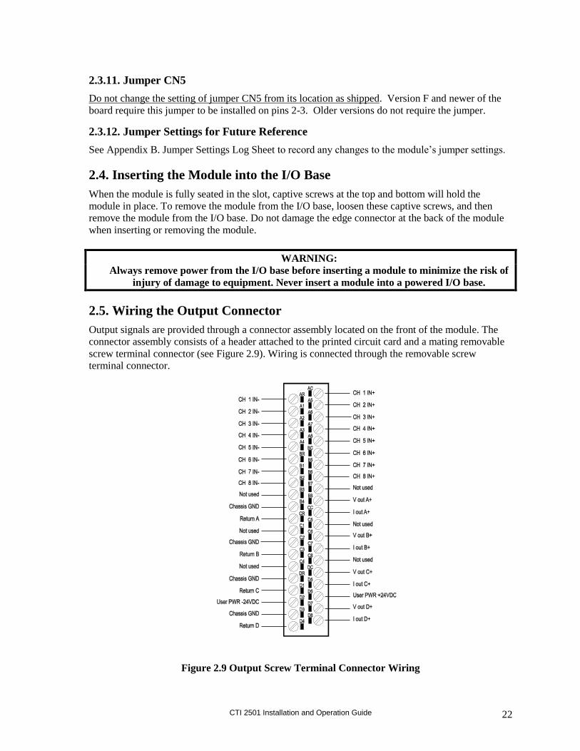
2.5. Wiring the Output Connector
Output signals are provided through a connector assembly located on the front of the module. The
connector assembly consists of a header attached to the printed circuit card and a mating removable
screw terminal connector (see Figure 2.9). Wiring is connected through the removable screw
terminal connector.
Figure 2.9 Output Screw Terminal Connector Wiring
CTI 2501 Installation and Operation Guide 23
2.5.1. Connecting Voltage Output Wiring
First, loosen the wire locking screws on the output screw terminal plug. For voltage output circuits,
connect the signal wire to the VOUT screw terminal, and the return wire to the Return (channel
ground) screw terminal. Insert the wires in the appropriate holes next to the screws. When the wires
are inserted, tighten the screws. Repeat this procedure for the remaining voltage output channels.
2.5.2. Connecting Current Output Wiring
For current output circuits, connect the signal wire to the IOUT screw terminal, and the return wire to
the Return (channel ground) screw terminal. Insert the wires in the appropriate holes next to the
screws. When the wires are inserted, tighten the screws. Repeat this procedure for the remaining
current output channels.
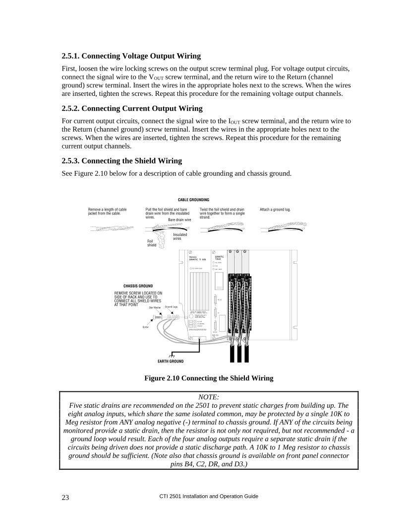
2.5.3. Connecting the Shield Wiring
See Figure 2.10 below for a description of cable grounding and chassis ground.
Figure 2.10 Connecting the Shield Wiring
NOTE:
Five static drains are recommended on the 2501 to prevent static charges from building up. The
eight analog inputs, which share the same isolated common, may be protected by a single 10K to
Meg resistor from ANY analog negative (-) terminal to chassis ground. If ANY of the circuits being
monitored provide a static drain, then the resistor is not only not required, but not recommended - a
ground loop would result. Each of the four analog outputs require a separate static drain if the
circuits being driven does not provide a static discharge path. A 10K to 1 Meg resistor to chassis
ground should be sufficient. (Note also that chassis ground is available on front panel connector
pins B4, C2, DR, and D3.)
CTI 2501 Installation and Operation Guide 24
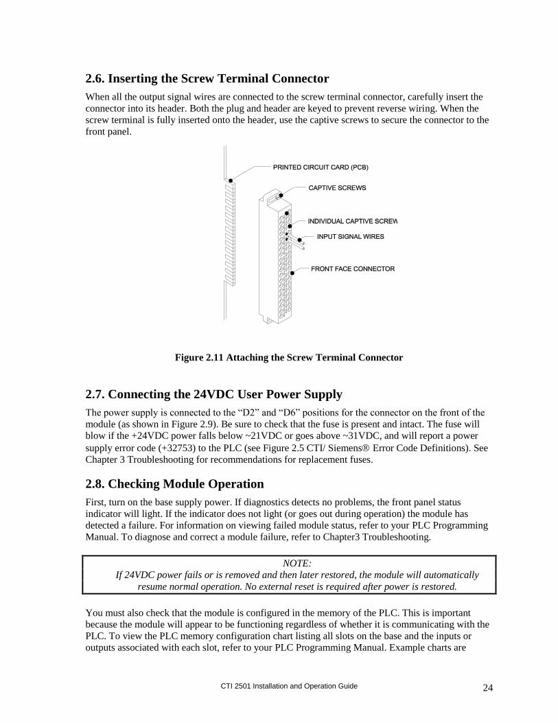
2.6. Inserting the Screw Terminal Connector
When all the output signal wires are connected to the screw terminal connector, carefully insert the
connector into its header. Both the plug and header are keyed to prevent reverse wiring. When the
screw terminal is fully inserted onto the header, use the captive screws to secure the connector to the
front panel.
Figure 2.11 Attaching the Screw Terminal Connector
2.7. Connecting the 24VDC User Power Supply
The power supply is connected to the “D2” and “D6” positions for the connector on the front of the
module (as shown in Figure 2.9). Be sure to check that the fuse is present and intact. The fuse will
blow if the +24VDC power falls below ~21VDC or goes above ~31VDC, and will report a power
supply error code (+32753) to the PLC (see Figure 2.5 CTI/ Siemens Error Code Definitions). See
Chapter 3 Troubleshooting for recommendations for replacement fuses.
2.8. Checking Module Operation
First, turn on the base supply power. If diagnostics detects no problems, the front panel status
indicator will light. If the indicator does not light (or goes out during operation) the module has
detected a failure. For information on viewing failed module status, refer to your PLC Programming
Manual. To diagnose and correct a module failure, refer to Chapter3 Troubleshooting.
NOTE:
If 24VDC power fails or is removed and then later restored, the module will automatically
resume normal operation. No external reset is required after power is restored.
You must also check that the module is configured in the memory of the PLC. This is important
because the module will appear to be functioning regardless of whether it is communicating with the
PLC. To view the PLC memory configuration chart listing all slots on the base and the inputs or
outputs associated with each slot, refer to your PLC Programming Manual. Example charts are

CTI 2501 Installation and Operation Guide 25
shown in the following figures, one for each login mode. Also, note the Wxs and Wys mix in Figure
2.12 below.
Module
Configuration
Analog
Inputs Outputs
I/O Words
Values
Lo, 7012 8WX
8 0 WX1-8 Input data 1-8 / error words
Lo, 7016 4WX
4WY
4 4 WX1-4
WY5-8
Input data 1-4 / error words
Output points A-D
Hi, 7012: 12WX
4WY
8 4 WX1-8
WX9-12
WY13-16
Input data / error words
Output echo / error words
Output points A-D
Hi, 7016: 20WX
4WY
8 4 WX1-8
WX9-16
WX17-20
WY21-24
Input data
Input error words
Output echo / error words
Output points A-D
Figure 2.12 WXs and Wys mix
In this first example, the 2501 Module is inserted in slot 1 in I/O base 0, logging in as a Lo Density
module (see Figure 2.13). Input data for channel 1 appears in word location WX1, data for channel 2
appears in word location WX2, etc. through channel 8 and WX8. For your particular module, look in
the chart for the number corresponding to the slot occupied by the module. If word memory locations
appear on this line, then the module is registered in the PLC memory and the module is ready for
operation.
I/O Module Definition for Channel…1 Base…..00
Number of Bit and Word I/O
Slot
I/O Address
X
Y
WX
WY
Special
Function
1 0001 00 00 08 00 NO
2 0000 00 00 00 00 NO
.
.
.
.
.
.
.
.
.
.
.
.
.
.
15 0000 00 00 00 00 NO
16 0000 00 00 00 00 NO
Figure 2.13 I/O Configuration Chart: Lo Density
In the second example, the 2501 Module is inserted in slot 1 in I/O base 0, logging in as a High
Density, 7012 module (see Figure 2.14). Input data for channel 1 appears in word location WX1,
data for channel 2 appears in word location WX2, etc. through channel 8 and WX8. Output data for
channels 9-12 appear in word locations WX 9-12. For your particular module, look in the chart for
the number corresponding to the slot occupied by the module. If word memory locations appear on
this line, then the module is registered in the PLC memory and the module is ready for operation.
CTI 2501 Installation and Operation Guide 26
I/O Module Definition for Channel…1 Base…..00
Number of Bit and Word I/O
Slot
I/O Address
X
Y
WX
WY
Special
Function
1 0001 00 00 12 04 NO
2 0000 00 00 00 00 NO
.
.
.
.
.
.
.
.
.
.
.
.
.
.
15 0000 00 00 00 00 NO
16 0000 00 00 00 00 NO
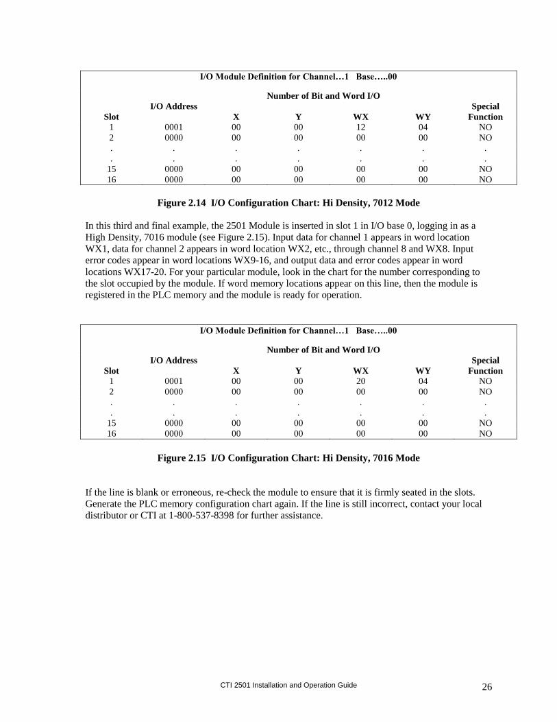
Figure 2.14 I/O Configuration Chart: Hi Density, 7012 Mode
In this third and final example, the 2501 Module is inserted in slot 1 in I/O base 0, logging in as a
High Density, 7016 module (see Figure 2.15). Input data for channel 1 appears in word location
WX1, data for channel 2 appears in word location WX2, etc., through channel 8 and WX8. Input
error codes appear in word locations WX9-16, and output data and error codes appear in word
locations WX17-20. For your particular module, look in the chart for the number corresponding to
the slot occupied by the module. If word memory locations appear on this line, then the module is
registered in the PLC memory and the module is ready for operation.
I/O Module Definition for Channel…1 Base…..00
Number of Bit and Word I/O
Slot
I/O Address
X
Y
WX
WY
Special
Function
1 0001 00 00 20 04 NO
2 0000 00 00 00 00 NO
.
.
.
.
.
.
.
.
.
.
.
.
.
.
15 0000 00 00 00 00 NO
16 0000 00 00 00 00 NO
Figure 2.15 I/O Configuration Chart: Hi Density, 7016 Mode
If the line is blank or erroneous, re-check the module to ensure that it is firmly seated in the slots.
Generate the PLC memory configuration chart again. If the line is still incorrect, contact your local
distributor or CTI at 1-800-537-8398 for further assistance.

CTI 2501 Installation and Operation Guide 27
NOTE:
In the event a CTI analog module detects no user 24VDC or an onboard module failure, the
module will assert the module fail line and report the module failure in the I/O Status Word,
which is reported to the PLC CPU. CTI strongly recommends the user application monitor the
I/O Module Status Words which are Status Words 11-26 and apply to Controllers TI/545,
TI/555, TI/560 & 565, and the TI/575. The I/O Module Status Word can be used to report a
module failure for an I/O Module in any of the 505 I/O slots. Please refer to Siemens 505
Programming Reference Manual for more information. If a module failure is reported by the
status word, the module should be replaced with a working unit and the failed module sent in for
repair.
2.9. Power Cycling
The 2501 reacts in the following ways upon various power cycling scenarios:
Base Power
(5V)
User Power
(24V)
2501 in Last Value Mode
Unipolar Mode* Bipolar Mode*
On
Transition off Output to zero. Output to zero.
On
Transition on Output from zero to PLC
value.
Output from zero to full
scale (+), then PLC value.
Transition off
On Maintains last value. Maintains last value.
Transition on
On Maintains last value. Maintains last value.
Off Transition on
Output stays at zero. Output to full scale.
Base Power
(5V)
User Power
(24V)
2501 in Zero Mode
Unipolar Mode* Bipolar Mode*
On
Transition off Output to zero. Output to zero.
On
Transition on Output from zero to PLC
value.
Output from zero to full
scale (+), then to zero,
then to PLC value.
Transition off
On Maintains last value. Maintains last value.
Transition on
On Output to zero for several
seconds, then to PLC
value.
Output to zero, then to
PLC value.
Off Transition on
Output stays at zero. Output from zero to full
scale (+).
*See Section 2.3.2. Selecting Either Zero or Last Value Output at Power Up for further explanation.

CTI 2501 Installation and Operation Guide 28
CHAPTER 3. TROUBLESHOOTING
SYMPTOM PROBABLE CAUSE CORRECTIVE ACTION
Indicator is not lit Base power is off Turn base on
Defective module Return module to CTI for repair
Indicator is blinking Calibration data is corrupted or missing Return module to CTI for calibration
PCB 901F-2501 only:
Jumper CN5 is missing
Install jumper at CN5 pins 2-3 “normal”
Incorrect inputs Blown fuse Replace fuse (see below)
Wrong addresses for word input Check program for correct word input addresses
Not logged in Read I/O configuration
Incorrect jumper or dipswitch setting Refer to Section 2.3 for settings
Incorrectly calibrated Return module to CTI for calibration
Noisy signal Check for proper shield termination at input connectors
Offset scale enabled If JP10 is enabled all inputs are scaled for offset operation
Figure 3.1 Troubleshooting Matrix
When it is inconvenient to visually check the status indicator, use the “Display Failed I/O" or "Show
PLC Diagnostics" support functions in your PLC programming software. Note that if the module
power supply (user supply) fails, the module will still be logged into the PLC even though it is not
operating. In this case, "Display Failed I/O" will not provide the information to accurately diagnose
the problem.
CAUTION:
The module fuse F2 is user serviceable. If this fuse continuously blows, the module has a
serious component failure and should be returned to CTI for repair, or the module is being
supplied voltage in excess of ~31VDC.
In the event the user serviceable fuse F2 blows, its replacement should be a 0.5 A, 250V Time Lag
5x20mm fuse (Schurter 0034.3114 or equivalent).
If after consulting the chart above, you are unable to diagnose or solve the problem, contact your
local distributor or CTI at 1-800-537-8398 for further assistance.


CTI 2501 Installation and Operation Guide 30

CTI 2501 Installation and Operation Guide 31
SPECIFICATIONS
Input Specs:
Input Channels: 8 analog input channels
Input Range: Unipolar: 0 to 5VDC, 0 to 10VDC, or 0 to 20mA
Bipolar: -5 to +5VDC, -10 to +10VDC, or -20 to +20mA
Resolution: Unipolar: 15 bits plus sign:
0-5VDC range=156V/step
0-10VDC range=312.5V/step
0-20mA range=0.625μA/step
Bipolar: 15 bits plus sign:
0-5VDC range=156V/step
0-10VDC range=312.5V/step
0-20mA range=0.625μA/step
Accuracy: Voltage Mode: 0.125% of full scale from 0° to 60°C
Current Mode: 0.225% of full scale from 0° to 60°C
Digital Filtering Time Constant: 0.3 Sec
DC Input Resistance: Voltage Mode: 780k
Current Mode: 250
Repeatability: 0.0025%
Common Mode Rejection: >120db @ 60Hz (digital filtering disabled)
Normal Mode Rejection: >40db @ 500Hz (digital filtering enabled)
Isolation 1500VDC channel-to-PLC
Input Protection: Input ESD Protection: 20,000V, IEC 1000-4-2, level 4
Overrange Protection: +/- 300VDC
Output Specs:
Output Channels: 4 analog output channels
Output Range: Unipolar: 0 to 5VDC, 0 to 10VDC, or 0 to 20mA
Bipolar: -5 to +5VDC, -10 to +10VDC, or -20 to +20mA
Resolution (7012 or 7016 Mode): Unipolar: 12 bits:
0-5VDC range = 1.25mV/step
0-10VDC range = 2.5mV/step
0-20mA range = 5A/step
Bipolar: 12 bits:
-5 to +5VDC range = 2.5mV/step
-10 to +10VDC range = 5.0mV/step
-20 to +20mA range = 10A/step
Accuracy: Voltage Mode: <1% of full scale from 0-60C over load range
Current Mode: <1% of full scale from 0-60C over load range
Capacitance Drive: 0.01 microfarads
Load Resistance: Voltage: 1KΩ minimum, no maximum
Current: 0Ω to 1KΩ max. @ 24VDC or greater
User Supply: 20 to 30VDC @ 0.25 Amps (maximum ripple of 0.4V) UL Class
2 power supply
Isolation: 1500VDC channel-to-channel and channel-to-PLC

CTI 2501 Installation and Operation Guide 32
Module Specs:
Update Time: 5.6 mSec all channels, LO Density Mode
6.7 mSec all channels, HI Density, 7012 or 7016 Mode
Connector: Removable
Wire Gauge: 14-22 AWG
User Serviceable Fuse: 0.5A, 250V time lag 5x20 mm (Schurter 0034.3114 or equiv.)
Backplane Power Consumption: 3.0 Watts
Module Size: Single-wide
Operating Temperature: 0 to 60C (32 to 140F)
Storage Temperature: -40 to 85C (-40 to 185F)
Relative Humidity: 5% to 95% non-condensing
Agency Approvals Pending: UL, UL-C, Class 1-Div 2, CE
Shipping Weight: 1.5 lb. (0.68 Kg)
*Specifications subject to change without notice.
CTI 2501 Installation and Operation Guide 33
APPENDIX A. COMPATIBILITY WITH SIEMENS 505-7012/7016
Overview
The CTI 2501 8 Analog Input / 4 Analog Output Module was designed to be a drop-in replacement
for the Siemens Models 505-7012 and 505-7016. From set up of the module to wiring and PLC
reporting, the user will find many similarities between the CTI and Siemens modules.
Using the CTI 2501 in a 505-7012 and/or 505-7016 application
The CTI 2501 should fulfill all the following requirements for the 505-7012 and 505-7016
replacement(s), as outlined below:
Module setup
Since the CTI 2501 allows for both Unipolar and Bipolar setup, the module does have a slightly
different module setup. See Chapter 2.3 Configuring the Module for Operation to determine the
details in module setup.
Wiring
The wiring of the output connector is the same between the modules. See Chapter 2.5. Wiring the
Output Connector for a detailed explanation of how this is accomplished.
If the module is used to supply voltage, the requirements of the input voltage to the module (20-
30VDC) remains the same in order to supply the resistive load of the field device (>1000).
However, the maximum load resistance for current output drops to 600 at 20VDC and then climbs
linearly to 1000 at 24-30VDC.
Also noteworthy is the isolation achieved module to module with the same power supply by using
the CTI 2501 versus the Siemens modules. With the 2501, each module is dielectrically isolated
from a common 24V power supply.
PLC Reporting
The word format is the same between the modules. See Chapter 1 for a more detailed explanation on
PLC reporting.
Power Cycling
When the user power is supplied and the base power is transitioning on, the 2501 has the option to
either transition to hold the last output value until the next PLC update, as the Siemens modules
do, or to go to zero until the next PLC update. See section 2.3.2. Selecting Either Zero or Last Value
Output at Power Up for further details.


CTI 2501 Installation and Operation Guide 35
APPENDIX B. JUMPER SETTINGS LOG SHEET
Channel
Number
Voltage
Current
Jumper
Jumper
Position V or 20mA
Voltage
Range
Jumper
Jumper
Position 5V or 10V
Unipolar/
Bipolar
Jumper
Jumper
Position Uni or Bi
1 JP14 JP5 JP4
2 JP15 JP22 JP6
3 JP16 JP23 JP7
4 JP17 JP24 JP8
5 JP18 JP25 JP9
6 JP19 JP26 JP11
7 JP20 JP27 JP12
8 JP21 JP28 JP13
A - JP29 JP33
B - JP30 JP34
C - JP31 JP35
D - JP32 JP36
All Channels
1-8 IN,
A-D OUT
Hi/Lo
Density Hi or Lo
Outputs at
Power Up Last or Zero
SIM
Mode 7012 or 7016
Output
Scaling Dis or En
Dig Fil/
Cal Mode Dis or En
Input
Scaling Dis or En
Jumper JP38 JP37 JP3 JP10 JP2 JP1
Jumper
Position
Record the configuration jumper settings on this log for future reference. Make additional copies if
necessary.

CTI 2501 Installation and Operation Guide 36

CTI 2501 Installation and Operation Guide 37
LIMITED PRODUCT WARRANTY
CTI warrants that this CTI Industrial Product shall be free from defects in material and workmanship
for a period of one (1) year after purchase from CTI or from an authorized CTI Industrial Distributor.
This CTI Industrial Product will be newly manufactured from new and/or serviceable used parts
which are equal to new in the Product.
Should this CTI Industrial Product fail to be free from defects in material and workmanship at any
time during this (1) year warranty period, CTI will repair or replace (at its option) parts or Products
found to be defective and shipped prepaid by the customer to a designated CTI service location along
with proof of purchase date and associated serial number. Repair parts and replacement Product
furnished under this warranty will be on an exchange basis and will be either reconditioned or new.
All exchanged parts or Products become the property of CTI. Should any Product or part returned to
CTI hereunder be found by CTI to be without defect, CTI will return such Product or part to the
customer.
This warranty does not include repair of damage to a part or Product resulting from: failure to
provide a suitable environment as specified in applicable Product specifications, or damage caused
by an accident, disaster, acts of God, neglect, abuse, misuse, transportation, alterations, attachments,
accessories, supplies, non-CTI parts, non-CTI repairs or activities, or to any damage whose
proximate cause was utilities or utility like services, or faulty installation or maintenance done by
someone other than CTI.
Control Technology Inc. reserves the right to make changes to the Product in order to improve
reliability, function, or design in the pursuit of providing the best possible Product. CTI assumes no
responsibility for indirect or consequential damages resulting from the use or application of this
equipment.
THE WARRANTY SET FORTH ABOVE IN THIS ARTICLE IS THE ONLY WARRANTY CTI
GRANTS AND IT IS IN LIEU OF ANY OTHER IMPLIED OR EXPRESSED GUARANTY OR
WARRANTY ON CTI PRODUCTS, INCLUDING WITHOUT LIMITATION, ANY
WARRANTY OF MERCHANTABILITY OR OF FITNESS FOR A PARTICULAR PURPOSE
AND IS IN LIEU OF ALL OBLIGATIONS OR LIABILITY OF CTI FOR DAMAGES IN
CONNECTION WITH LOSS, DELIVERY, USE OR PERFORMANCE OF CTI PRODUCTS OR
INTERRUPTION OF BUSINESS, LOSS OF USE, REVENUE OR PROFIT. IN NO EVENT
WILL CTI BE LIABLE FOR SPECIAL, INCIDENTAL, OR CONSEQUENTIAL DAMAGES.
SOME STATES DO NOT ALLOW THE EXCLUSION OR LIMITATION OF INCIDENTAL OR
CONSEQUENTIAL DAMAGES FOR CONSUMER PRODUCTS, SO THE ABOVE
LIMITATIONS OR EXCLUSIONS MAY NOT APPLY TO YOU.
THIS WARRANTY GIVES YOU SPECIFIC LEGAL RIGHTS, AND YOU MAY ALSO HAVE
OTHER RIGHTS WHICH MAY VARY FROM STATE TO STATE.
CTI 2501 Installation and Operation Guide 38
REPAIR POLICY
In the event that the Product should fail during or after the warranty period, a Return Material
Authorization (RMA) number can be requested orally or in writing from CTI main offices. Whether this
equipment is in or out of warranty, a Purchase Order number provided to CTI when requesting the RMA
number will aid in expediting the repair process. The RMA number that is issued and your Purchase
Order number should be referenced on the returning equipment's shipping documentation. Additionally,
if the product is under warranty, proof of purchase date and serial number must accompany the returned
equipment. The current repair and/or exchange rates can be obtained by contacting CTI's office at
1-800-537-8398.
When returning any module to CTI, follow proper static control precautions. Keep the module away from
polyethylene products, polystyrene products and all other static producing materials. Packing the module
in its original conductive bag is the preferred way to control static problems during shipment. Failure to
observe static control precautions may void the warranty. For additional information on static control
precautions, contact CTI's office at 1-800-537-8398.