Embed Size (px)
Citation preview

CT RaceWorx 6 Piece X3 Gusset Kit
Installation instructions
Parts list: 1.Front bulkhead plate 2.Inner bulkhead plate 3.Billet Al support block 4.Lower A-arm rear support 5.Upper A-arm inner support 6.Inner support to frame bracket Hardware list: (2) 12mmx1.75-100mm (2) 12mm flat washers (12) 3/8x16-1” bolts (12) 3/8 flat washers (4) 3/8x16 toploc nuts (2) 5/16x18-1” bolts (4) 5/16 flat washers (2) 5/16x18 toploc nuts (3) zip ties Tools required: T30 torx T20 torx 10mm wrench and/or socket (2) 18 mm sockets and ratchets Extensions for sockets 18 mm wrench 15mm socket and or wrench 9/16” wrench 9/16” socket ½” wrench ½” socket
NOTE: Front wheels and main front suspension components must be removed to install this product.
The vehicle must be securely supported and wheels must be securely chocked. While it is possible to
install this kit single handedly it is much easier with an extra set of hands.
Disassembly:
Not all parts, such as the front hood plastics and radiator grill with light assemblies, must be removed.
However, they can be removed as one assembly and makes installation of the gusset kit much easier.
Step 1: To remove the front hood/grill assembly, pop out the small cover in front of the shocks, it’s
held on by grommets. Next disconnect 2 headlight plugs on each side of the vehicle. Remove the small
T20 torx screw holding the headlight adjuster screws. Gently pull the adjusters back so they slide off
when hood is removed. Using a T30 torx remove 4 bolts on the lower plastic, 2 at the top of the
radiator, 4 (2 each side) underneath the sides of the hood located at the firewall. 2 screws at the
headlights have a 10mm nut on the back. 2 screws on each side located by the a-pillar one behind gas
cover. The top plastic cover has 4 blind plastic clips, these easily pop up with gentle force. There are two
(one on each side) visible from underneath. These can be carefully slid off their tabs by gently opening
them. The hood assembly can be gently removed and set aside.
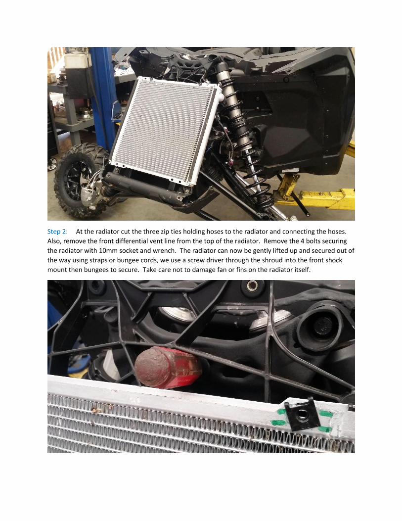
Step 2: At the radiator cut the three zip ties holding hoses to the radiator and connecting the hoses.
Also, remove the front differential vent line from the top of the radiator. Remove the 4 bolts securing
the radiator with 10mm socket and wrench. The radiator can now be gently lifted up and secured out of
the way using straps or bungee cords, we use a screw driver through the shroud into the front shock
mount then bungees to secure. Take care not to damage fan or fins on the radiator itself.
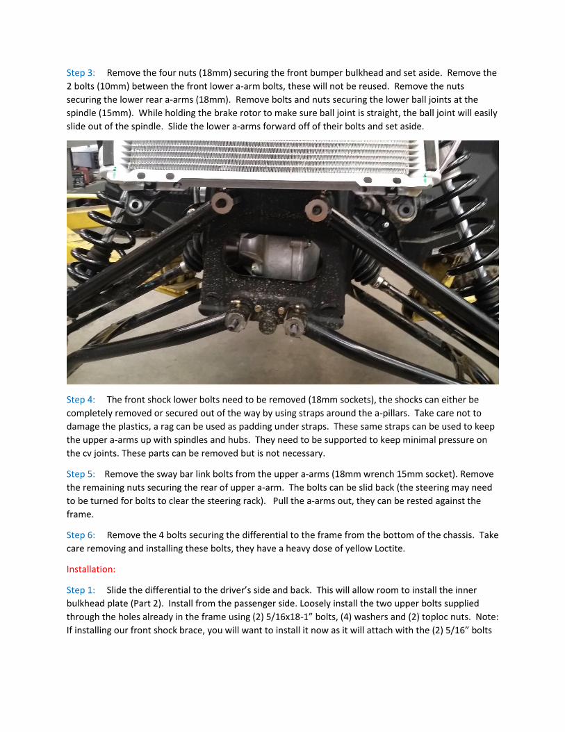
Step 3: Remove the four nuts (18mm) securing the front bumper bulkhead and set aside. Remove the
2 bolts (10mm) between the front lower a-arm bolts, these will not be reused. Remove the nuts
securing the lower rear a-arms (18mm). Remove bolts and nuts securing the lower ball joints at the
spindle (15mm). While holding the brake rotor to make sure ball joint is straight, the ball joint will easily
slide out of the spindle. Slide the lower a-arms forward off of their bolts and set aside.
Step 4: The front shock lower bolts need to be removed (18mm sockets), the shocks can either be
completely removed or secured out of the way by using straps around the a-pillars. Take care not to
damage the plastics, a rag can be used as padding under straps. These same straps can be used to keep
the upper a-arms up with spindles and hubs. They need to be supported to keep minimal pressure on
the cv joints. These parts can be removed but is not necessary.
Step 5: Remove the sway bar link bolts from the upper a-arms (18mm wrench 15mm socket). Remove
the remaining nuts securing the rear of upper a-arm. The bolts can be slid back (the steering may need
to be turned for bolts to clear the steering rack). Pull the a-arms out, they can be rested against the
frame.
Step 6: Remove the 4 bolts securing the differential to the frame from the bottom of the chassis. Take
care removing and installing these bolts, they have a heavy dose of yellow Loctite.
Installation:
Step 1: Slide the differential to the driver’s side and back. This will allow room to install the inner
bulkhead plate (Part 2). Install from the passenger side. Loosely install the two upper bolts supplied
through the holes already in the frame using (2) 5/16x18-1” bolts, (4) washers and (2) toploc nuts. Note:
If installing our front shock brace, you will want to install it now as it will attach with the (2) 5/16” bolts
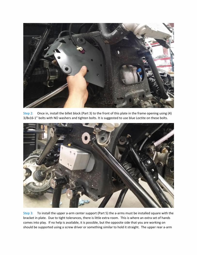
Step 2: Once in, install the billet block (Part 3) to the front of this plate in the frame opening using (4)
3/8x16-1” bolts with NO washers and tighten bolts. It is suggested to use blue Loctite on these bolts.
Step 3: To install the upper a-arm center support (Part 5) the a-arms must be installed square with the
bracket in plate. Due to tight tolerances, there is little extra room. This is where an extra set of hands
comes into play. If no help is available, it is possible, but the opposite side that you are working on
should be supported using a screw driver or something similar to hold it straight. The upper rear a-arm
bolts are reused. The front bolts are replaced with the (2) 12x1.75-100mm bolts and (2) 12mm washers
supplied in the kit. These bolts are installed from the inside pointing toward the front of the vehicle. Do
not tighten bolts at this time.
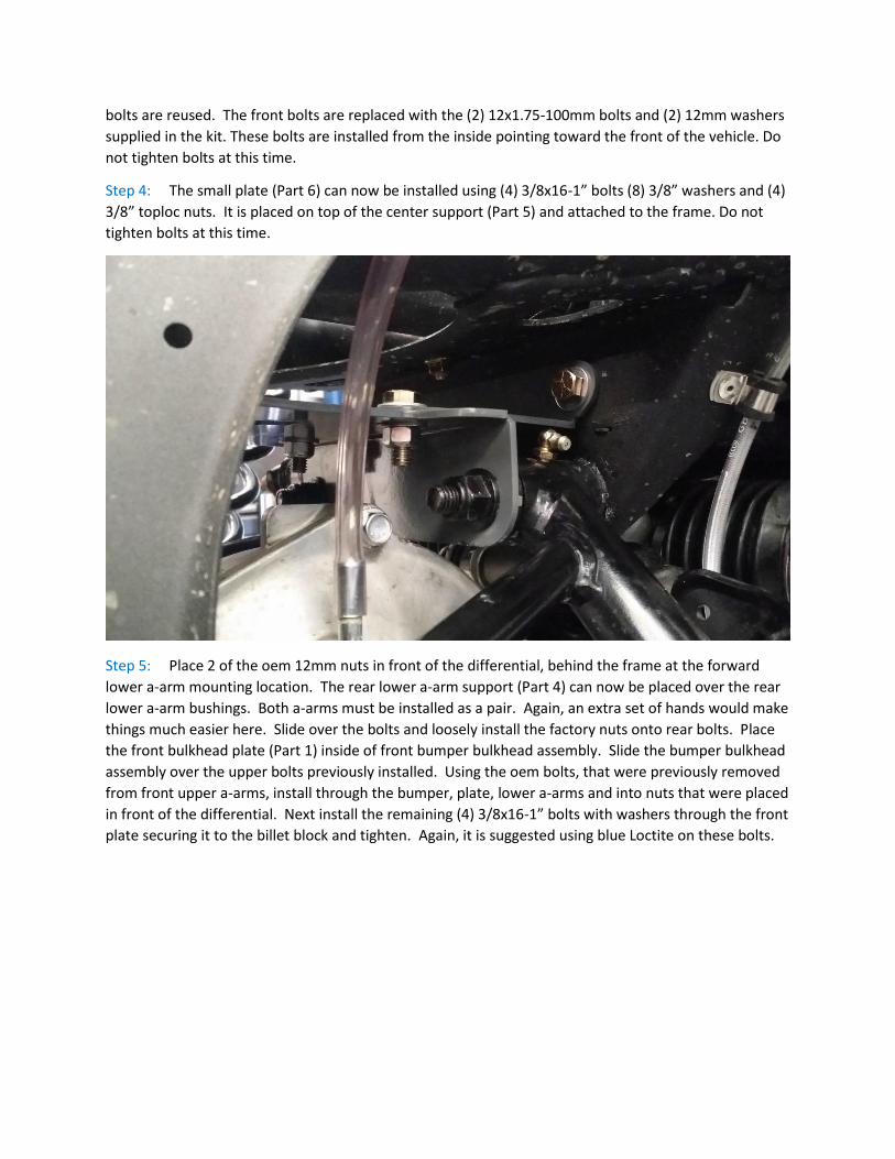
Step 4: The small plate (Part 6) can now be installed using (4) 3/8x16-1” bolts (8) 3/8” washers and (4)
3/8” toploc nuts. It is placed on top of the center support (Part 5) and attached to the frame. Do not
tighten bolts at this time.
Step 5: Place 2 of the oem 12mm nuts in front of the differential, behind the frame at the forward
lower a-arm mounting location. The rear lower a-arm support (Part 4) can now be placed over the rear
lower a-arm bushings. Both a-arms must be installed as a pair. Again, an extra set of hands would make
things much easier here. Slide over the bolts and loosely install the factory nuts onto rear bolts. Place
the front bulkhead plate (Part 1) inside of front bumper bulkhead assembly. Slide the bumper bulkhead
assembly over the upper bolts previously installed. Using the oem bolts, that were previously removed
from front upper a-arms, install through the bumper, plate, lower a-arms and into nuts that were placed
in front of the differential. Next install the remaining (4) 3/8x16-1” bolts with washers through the front
plate securing it to the billet block and tighten. Again, it is suggested using blue Loctite on these bolts.
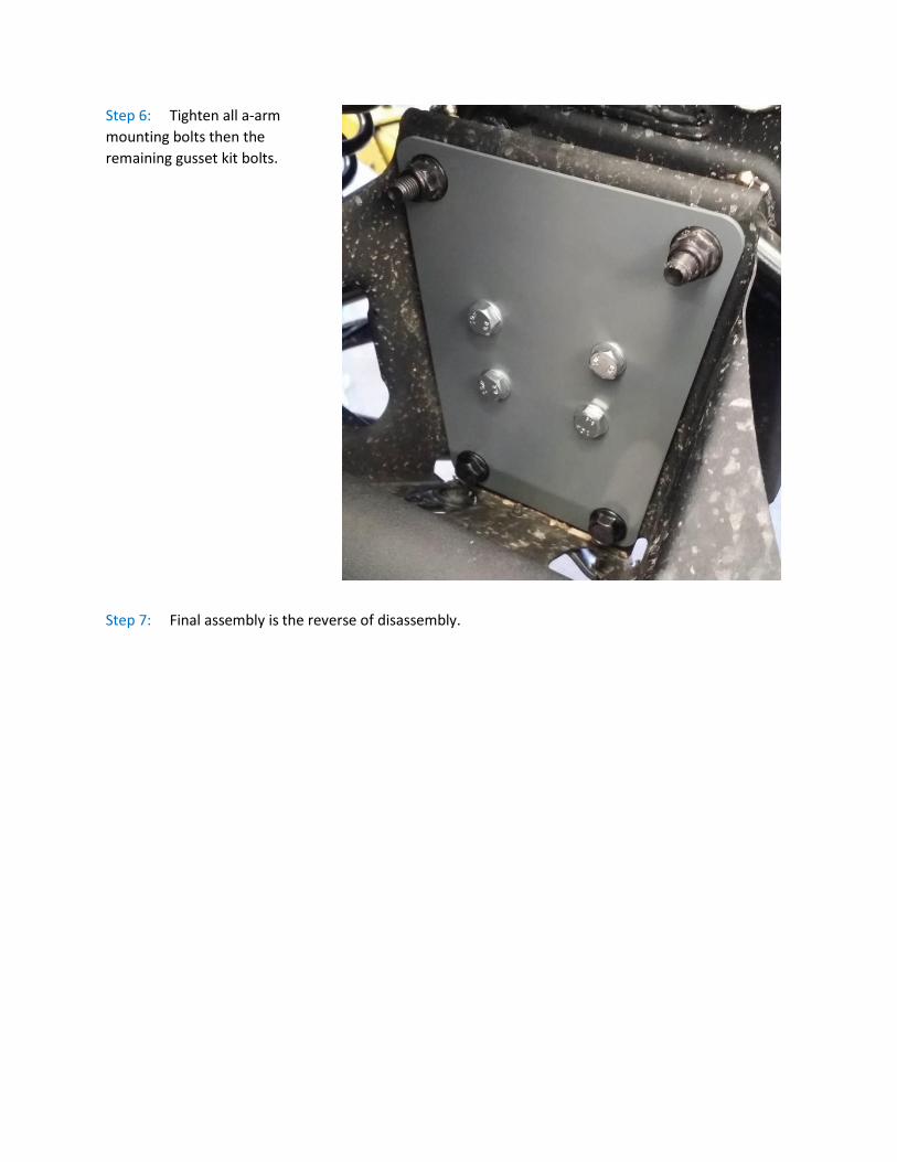
Step 6: Tighten all a-arm
mounting bolts then the
remaining gusset kit bolts.
Step 7: Final assembly is the reverse of disassembly.