Embed Size (px)
Citation preview
8/21/2019 Gusset Plates
http://slidepdf.com/reader/full/gusset-plates 1/12
ENGINEERING JOURNAL / SECOND QUARTER / 2006 / 91
Objective
The objectives of this research were to determine the accu-
racy of the current design method using a statistical analysis
of data from the available research, and to propose appro-
priate effective length factors for use in the current design
procedures.
Procedure
The available experimental and finite element data on the
buckling capacity of gusset plates was collected and re-
viewed. The experimental and finite element capacities werecompared with the calculated nominal loads for each speci-
men, and the most appropriate effective length factor was
selected for each gusset plate configuration. The accuracy of
the design method was determined using the selected effec-
tive length factors.
Gusset Plate Configurations
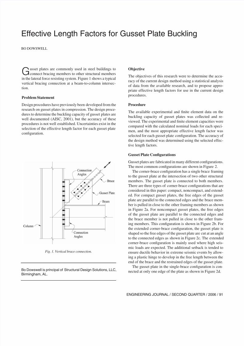
Gusset plates are fabricated in many different configurations.
The most common configurations are shown in Figure 2.
The corner-brace configuration has a single brace framing
to the gusset plate at the intersection of two other structural
members. The gusset plate is connected to both members.There are three types of corner-brace configurations that are
considered in this paper: compact, noncompact, and extend-
ed. For compact gusset plates, the free edges of the gusset
plate are parallel to the connected edges and the brace mem-
ber is pulled in close to the other framing members as shown
in Figure 2a. For noncompact gusset plates, the free edges
of the gusset plate are parallel to the connected edges and
the brace member is not pulled in close to the other fram-
ing members. This configuration is shown in Figure 2b. For
the extended corner-brace configuration, the gusset plate is
shaped so the free edges of the gusset plate are cut at an angle
to the connected edges as shown in Figure 2c. The extended
corner-brace configuration is mainly used where high seis-mic loads are expected. The additional setback is tended to
ensure ductile behavior in extreme seismic events by allow-
ing a plastic hinge to develop in the free length between the
end of the brace and the restrained edges of the gusset plate.
The gusset plate in the single-brace configuration is con-
nected at only one edge of the plate as shown in Figure 2d.
Effective Length Factors for Gusset Plate Buckling
BO DOWSWELL
Gusset plates are commonly used in steel buildings to
connect bracing members to other structural members
in the lateral force resisting system. Figure 1 shows a typical
vertical bracing connection at a beam-to-column intersec-
tion.
Problem Statement
Design procedures have previously been developed from the
research on gusset plates in compression. The design proce-
dures to determine the buckling capacity of gusset plates are
well documented (AISC, 2001), but the accuracy of these
procedures is not well established. Uncertainties exist in the
selection of the effective length factor for each gusset plate
configuration.
Bo Dowswell is principal of Structural Design Solutions, LLC,
Birmingham, AL.
Fig. 1. Vertical brace connection.
8/21/2019 Gusset Plates
http://slidepdf.com/reader/full/gusset-plates 2/12
92 / ENGINEERING JOURNAL / SECOND QUARTER / 2006
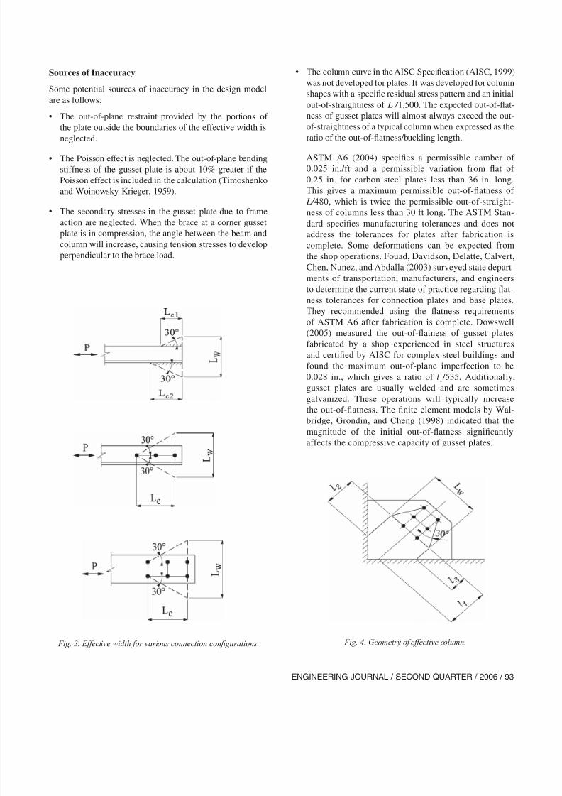
For corner gusset plates, the column length, lavg is calculated
as the average of l1, l2 , and l3 as shown in Figure 4. The
buckling capacity is then calculated using the column curve
in the AISC Load and Resistance Factor Design Specifica-
tion for Structural Steel Buildings (AISC, 1999), hereafter
referred to as the AISC Specification.
The AISC Load and Resistance Factor Design Manualof Steel Construction, Volume II, Connections (AISC, 1995)
provides effective length factors for compact corner gusset
plates, noncompact corner gusset plates, and single-brace
gusset plates. The effective length factors and the suggested
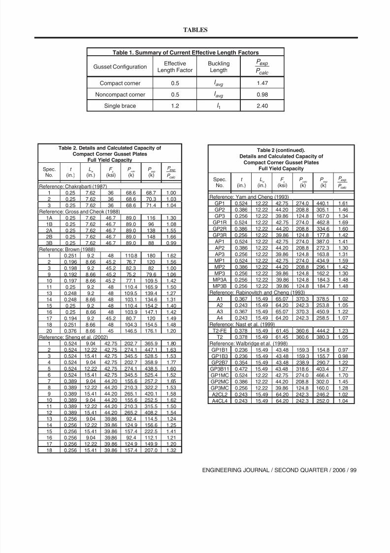
buckling lengths are summarized in Table 1. (Tables begin
on page 99.) Table 1 also shows the average ratio of experi-
mental buckling load to calculated nominal capacity based
on the tests and finite element models in Tables 2, 3, and 5.
The current design method is conservative by 47% for com-
pact corner gusset plates and is conservative by 140%
for single-brace gusset plates. The current design method
for noncompact corner gusset plates appears to be accurate
based on the test-to-predicted ratio of 0.98; however, thestandard deviation is 0.46, and the test-to-predicted ratio was
as low as 0.33 for one of the specimens. There appears to be
a source of improvement in the design procedure for these
three gusset plate configurations by simply selecting an ef-
fective length factor that gives predicted capacities closer to
the test and finite element results.
The chevron-brace configuration has two braces framing
to the gusset plate as shown in Figure 2e. The gusset plate is
connected at only one edge of the plate.
CURRENT DESIGN PROCEDURES
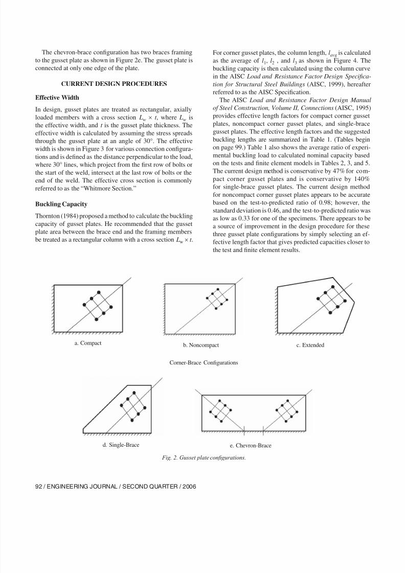
Effective WidthIn design, gusset plates are treated as rectangular, axially
loaded members with a cross section Lw × t , where Lw is
the effective width, and t is the gusset plate thickness. The
effective width is calculated by assuming the stress spreads
through the gusset plate at an angle of 30°. The effective
width is shown in Figure 3 for various connection configura-
tions and is defined as the distance perpendicular to the load,
where 30° lines, which project from the first row of bolts or
the start of the weld, intersect at the last row of bolts or the
end of the weld. The effective cross section is commonly
referred to as the “Whitmore Section.”
Buckling Capacity
Thornton (1984) proposed a method to calculate the buckling
capacity of gusset plates. He recommended that the gusset
plate area between the brace end and the framing members
be treated as a rectangular column with a cross section Lw × t .
c. Extendedb. Noncompacta. Compact
e. Chevron-Braced. Single-Brace
Corner-Brace Configurations
Fig. 2. Gusset plate configurations.
8/21/2019 Gusset Plates
http://slidepdf.com/reader/full/gusset-plates 3/12
ENGINEERING JOURNAL / SECOND QUARTER / 2006 / 93
Sources of Inaccuracy
Some potential sources of inaccuracy in the design model
are as follows:
• The out-of-plane restraint provided by the portions of
the plate outside the boundaries of the effective width is
neglected.
• The Poisson effect is neglected. The out-of-plane bending
stiffness of the gusset plate is about 10% greater if the
Poisson effect is included in the calculation (Timoshenko
and Woinowsky-Krieger, 1959).
• The secondary stresses in the gusset plate due to frame
action are neglected. When the brace at a corner gusset
plate is in compression, the angle between the beam and
column will increase, causing tension stresses to develop
perpendicular to the brace load.
• The column curve in the AISC Specification (AISC, 1999)
was not developed for plates. It was developed for column
shapes with a specific residual stress pattern and an initial
out-of-straightness of L / 1,500. The expected out-of-flat-
ness of gusset plates will almost always exceed the out-
of-straightness of a typical column when expressed as the
ratio of the out-of-flatness/buckling length.
ASTM A6 (2004) specifies a permissible camber of
0.025 in./ft and a permissible variation from flat of
0.25 in. for carbon steel plates less than 36 in. long.
This gives a maximum permissible out-of-flatness of
L/ 480, which is twice the permissible out-of-straight-
ness of columns less than 30 ft long. The ASTM Stan-
dard specifies manufacturing tolerances and does not
address the tolerances for plates after fabrication is
complete. Some deformations can be expected from
the shop operations. Fouad, Davidson, Delatte, Calvert,
Chen, Nunez, and Abdalla (2003) surveyed state depart-
ments of transportation, manufacturers, and engineersto determine the current state of practice regarding flat-
ness tolerances for connection plates and base plates.
They recommended using the flatness requirements
of ASTM A6 after fabrication is complete. Dowswell
(2005) measured the out-of-flatness of gusset plates
fabricated by a shop experienced in steel structures
and certified by AISC for complex steel buildings and
found the maximum out-of-plane imperfection to be
0.028 in., which gives a ratio of l1 /535. Additionally,
gusset plates are usually welded and are sometimes
galvanized. These operations will typically increase
the out-of-flatness. The finite element models by Wal-
bridge, Grondin, and Cheng (1998) indicated that themagnitude of the initial out-of-flatness significantly
affects the compressive capacity of gusset plates.
Fig. 3. Effective width for various connection configurations. Fig. 4. Geometry of effective column.
8/21/2019 Gusset Plates
http://slidepdf.com/reader/full/gusset-plates 4/12
94 / ENGINEERING JOURNAL / SECOND QUARTER / 2006
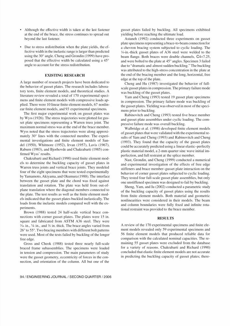
• Although the effective width is taken at the last fastener
at the end of the brace, the stress continues to spread out
beyond the last fastener.
• Due to stress redistribution when the plate yields, the ef-
fective width in the inelastic range is larger than predicted
using the 30° angle. Cheng and Grondin (1999) have pro-posed that the effective width be calculated using a 45°
angle to account for the stress redistribution.
EXISTING RESEARCH
A large number of research projects have been dedicated to
the behavior of gusset plates. The research includes labora-
tory tests, finite element models, and theoretical studies. A
literature review revealed a total of 170 experimental speci-
mens and finite element models with compressive loads ap-
plied. There were 10 linear finite element models, 67 nonlin-
ear finite element models, and 93 experimental specimens.
The first major experimental work on gusset plates wasby Wyss (1926). The stress trajectories were plotted for gus-
set plate specimens representing a Warren truss joint. The
maximum normal stress was at the end of the brace member.
Wyss noted that the stress trajectories were along approxi-
mately 30° lines with the connected member. The experi-
mental investigations and finite element models of San-
del (1950), Whitmore (1952), Irvan (1957), Lavis (1967),
Raburn (1983), and Bjorhovde and Chakrabarti (1985) con-
firmed Wyss’ results.
Chakrabarti and Richard (1990) used finite element mod-
els to determine the buckling capacity of gusset plates in
Warren truss joints and vertical brace joints. They modeled
four of the eight specimens that were tested experimentallyby Yamamoto, Akiyama, and Okumura (1988). The interface
between the gusset plate and the chord was fixed against
translation and rotation. The plate was held from out-of-
plane translation where the diagonal members connected to
the plate. The test results as well as the finite element mod-
els indicated that the gusset plates buckled inelastically. The
loads from the inelastic models compared well with the ex-
periments.
Brown (1988) tested 24 half-scale vertical brace con-
nections with corner gusset plates. The plates were 15 in.
square and fabricated from ASTM A36 steel. They were
x in., � in., and a in. thick. The brace angles varied from
26° to 55°. Two bracing members with different bolt patterns
were used. Most of the tests failed by buckling of the longer
free edge.
Gross and Cheok (1988) tested three nearly full-scale
braced frame subassemblies. The specimens were loaded
in tension and compression. The main parameters of study
were the gusset geometry, eccentricity of forces in the con-
nection, and orientation of the column. All but one of the
gusset plates failed by buckling. All specimens exhibited
yielding before reaching the ultimate load.
Astaneh (1992) conducted three experiments on gusset
plate specimens representing a brace-to-beam connection for
a chevron bracing system subjected to cyclic loading. The
4-in.-thick gusset plates of A36 steel were welded to the
beam flange. Both braces were double channels, C4×7.25,and were bolted to the plate at 45° angles. Specimen 3 failed
due to “dramatic and almost sudden buckling.” The buckling
was attributed to the high-stress concentration in the plate at
the end of the bracing member and the long, horizontal, free
edge at the top of the plate.
Cheng and Hu (1987) investigated the behavior of full-
scale gusset plates in compression. The primary failure mode
was buckling of the gusset plates.
Yam and Cheng (1993) tested 19 gusset plate specimens
in compression. The primary failure mode was buckling of
the gusset plates. Yielding was observed in most of the speci-
mens prior to buckling.
Rabinovitch and Cheng (1993) tested five brace memberand gusset plate assemblies under cyclic loading. The com-
pressive failure mode was overall buckling.
Walbridge et al. (1998) developed finite element models
of gusset plates that were validated with the experimental re-
sults of Yam and Cheng (1993) and Rabinovitch and Cheng
(1993). They found that the capacity of the gusset plates
could be accurately predicted using a linear elastic–perfectly
plastic material model, a 2-mm quarter sine wave initial im-
perfection, and full restraint at the splice member.
Nast, Grondin, and Cheng (1999) conducted a numerical
and experimental investigation of the effects of free edge
stiffeners and brace member–gusset plate interaction on the
behavior of corner gusset plates subjected to cyclic loading.
They tested four full-scale gusset plate assemblies, but only
one unstiffened specimen was designed to fail by buckling.
Sheng, Yam, and Iu (2002) conducted a parametric study
of the buckling capacity of gusset plates using the results
from finite element models. Both material and geometric
nonlinearities were considered in their models. The beam
and column boundaries were fully fixed and infinite rota-
tional restraint was provided to the brace member.
RESULTS
A review of the 170 experimental specimens and finite ele-
ment models revealed only 59 experimental specimens and56 finite element models that produced reliable data for
comparison with the calculated nominal capacities. The re-
maining 55 gusset plates were excluded from the database
for a variety of reasons. Chakrabarti and Richard (1990)
concluded that elastic finite element models are not accurate
in predicting the buckling capacity of gusset plates; there-
8/21/2019 Gusset Plates
http://slidepdf.com/reader/full/gusset-plates 5/12
ENGINEERING JOURNAL / SECOND QUARTER / 2006 / 95
fore, the finite element models with elastic material models
were excluded. An experimental specimen was excluded for
the following reasons: It was not loaded to failure, it had
a failure mode other than buckling, it was loaded with an
out-of-plane eccentricity, the plate had edge stiffeners, or
sufficient data were not available.
The current design procedure is semi-empirical, with theempirical aspects of the design method being the 30° stress
trajectory in the plate, the buckling length, and the effective
length factor. The accuracy of the 30° stress trajectory in the
elastic range is well established; therefore, only the buckling
length and the effective length factor were examined in this
paper.
Walbridge et al. (1998) showed that the accuracy of fi-
nite element models is dependent on the level of mesh re-
finement, the initial out-of-flatness of the plate, the material
model, the boundary conditions, and other characteristics of
the model. Because of this, the experimental specimens were
given a higher level of confidence in the selection of the pro-
posed effective length factors.For corner gusset plates, where there were many experi-
mental results, the finite element models of Sheng et al.
(2002) consistently predicted capacities that were higher
than average. This was taken into account in the selection
of the effective length factor for extended corner braces and
single braces, where almost all of the specimens were from
Sheng et al. (2002).
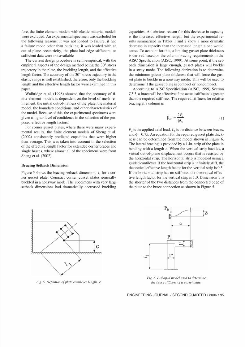
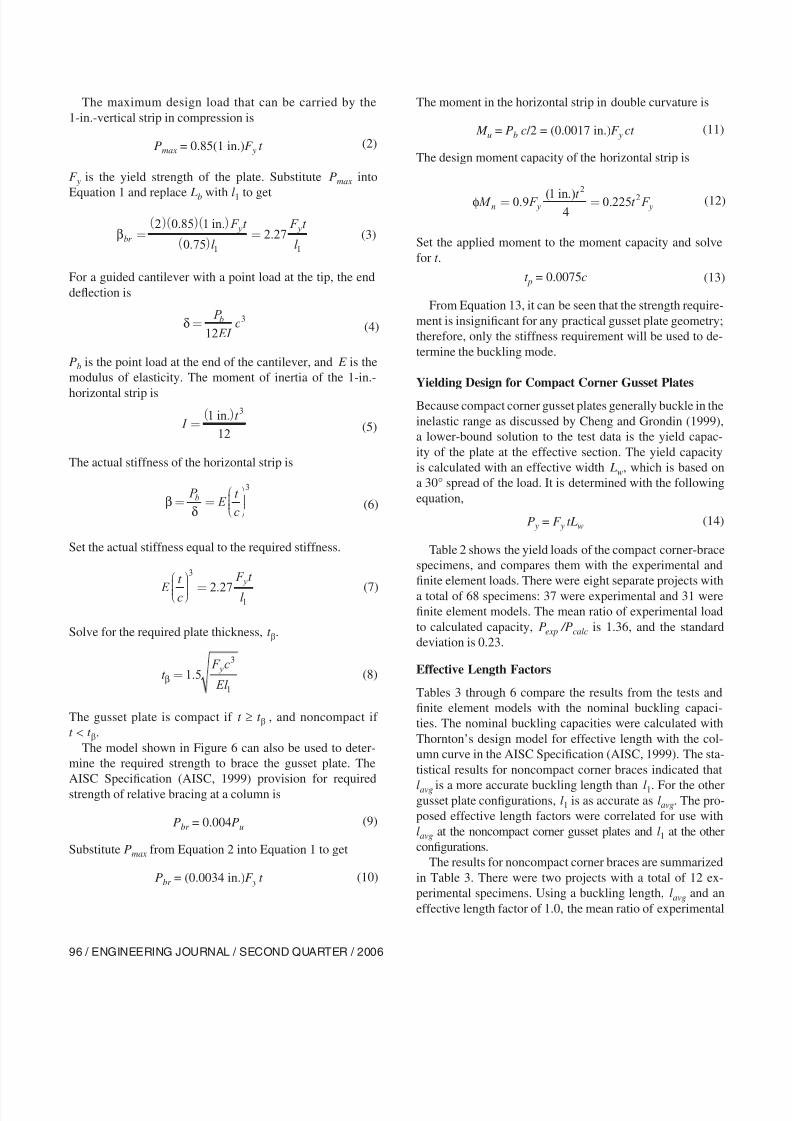
Bracing Setback Dimension
Figure 5 shows the bracing setback dimension, l1 for a cor-
ner gusset plate. Compact corner gusset plates generally
buckled in a nonsway mode. The specimens with very largesetback dimensions had dramatically decreased buckling
capacities. An obvious reason for this decrease in capacity
is the increased effective length, but the experimental re-
sults summarized in Tables 1 and 2 show a more dramatic
decrease in capacity than the increased length alone would
cause. To account for this, a limiting gusset plate thickness
is derived based on the column bracing requirements in the
AISC Specification (AISC, 1999). At some point, if the set-back dimension is large enough, gusset plates will buckle
in a sway mode. The following derivation is to determine
the minimum gusset plate thickness that will force the gus-
set plate to buckle in a nonsway mode. This will be used to
determine if the gusset plate is compact or noncompact.
According to AISC Specification (AISC, 1999) Section
C3.3, a brace will be effective if the actual stiffness is greater
than the required stiffness. The required stiffness for relative
bracing at a column is
Pu is the applied axial load, Lb is the distance between braces,
and φ = 0.75. An equation for the required gusset plate thick-
ness can be determined from the model shown in Figure 6.
The lateral bracing is provided by a 1-in. strip of the plate in
bending with a length c. When the vertical strip buckles, a
virtual out-of-plane displacement occurs that is resisted by
the horizontal strip. The horizontal strip is modeled using a
guided cantilever. If the horizontal strip is infinitely stiff, the
theoretical effective length factor for the vertical strip is 0.5.
If the horizontal strip has no stiffness, the theoretical effec-
tive length factor for the vertical strip is 1.0. Dimension c is
the shorter of the two distances from the connected edge ofthe plate to the brace connection as shown in Figure 5.
β
φbr
u
b
P
L
= 2
Fig. 5. Definition of plate cantilever length, c.
(1)
Fig. 6. L-shaped model used to determine
the brace stiffness of a gusset plate.
8/21/2019 Gusset Plates
http://slidepdf.com/reader/full/gusset-plates 6/12
96 / ENGINEERING JOURNAL / SECOND QUARTER / 2006
The maximum design load that can be carried by the
1-in.-vertical strip in compression is
Pmax = 0.85(1 in.)F y t
F y is the yield strength of the plate. Substitute Pmax into
Equation 1 and replace Lb with l1 to get
For a guided cantilever with a point load at the tip, the end
deflection is
Pb is the point load at the end of the cantilever, and E is the
modulus of elasticity. The moment of inertia of the 1-in.-
horizontal strip is
The actual stiffness of the horizontal strip is
Set the actual stiffness equal to the required stiffness.
Solve for the required plate thickness, t β.
The gusset plate is compact if t ≥ t β , and noncompact if
t < t β.
The model shown in Figure 6 can also be used to deter-
mine the required strength to brace the gusset plate. The
AISC Specification (AISC, 1999) provision for required
strength of relative bracing at a column is
Pbr = 0.004Pu
Substitute Pmax from Equation 2 into Equation 1 to get
Pbr = (0.0034 in.)F y t
The moment in the horizontal strip in double curvature is
M u = Pb c /2 = (0.0017 in.)F y ct
The design moment capacity of the horizontal strip is
Set the applied moment to the moment capacity and solve
for t .
t p = 0.0075c
From Equation 13, it can be seen that the strength require-
ment is insignificant for any practical gusset plate geometry;
therefore, only the stiffness requirement will be used to de-
termine the buckling mode.
Yielding Design for Compact Corner Gusset Plates
Because compact corner gusset plates generally buckle in the
inelastic range as discussed by Cheng and Grondin (1999),
a lower-bound solution to the test data is the yield capac-
ity of the plate at the effective section. The yield capacity
is calculated with an effective width Lw, which is based on
a 30° spread of the load. It is determined with the following
equation,
P y = F y tLw
Table 2 shows the yield loads of the compact corner-brace
specimens, and compares them with the experimental and
finite element loads. There were eight separate projects with
a total of 68 specimens: 37 were experimental and 31 were
finite element models. The mean ratio of experimental load
to calculated capacity, Pexp /Pcalc is 1.36, and the standard
deviation is 0.23.
Effective Length Factors
Tables 3 through 6 compare the results from the tests and
finite element models with the nominal buckling capaci-
ties. The nominal buckling capacities were calculated with
Thornton’s design model for effective length with the col-
umn curve in the AISC Specification (AISC, 1999). The sta-
tistical results for noncompact corner braces indicated that
lavg is a more accurate buckling length than l1. For the othergusset plate configurations, l1 is as accurate as lavg. The pro-
posed effective length factors were correlated for use with
lavg at the noncompact corner gusset plates and l1 at the other
configurations.
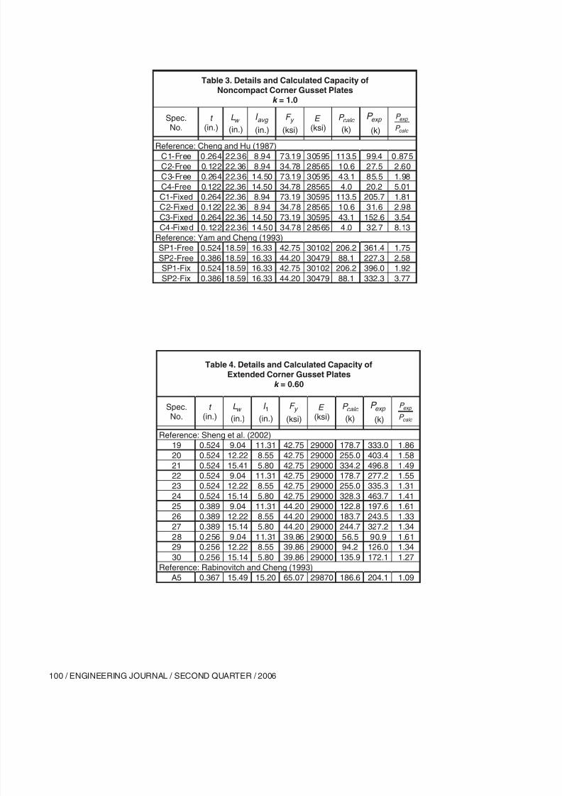
The results for noncompact corner braces are summarized
in Table 3. There were two projects with a total of 12 ex-
perimental specimens. Using a buckling length, lavg and an
effective length factor of 1.0, the mean ratio of experimental
I t
=( )1
12
3 in.
(5)
(2)
βbr
y y F t
l
F t
l =
( )( )( )
( ) =
2 0 85 1
0 752 27
1 1
.
..
in.(3)
δ = P
EI cb
12
3(4)
βδ
= =
P E
t
c
b
3
(6)
E
t
c
F t
l
y
=
3
12 27. (7)
t F c
El
y
β = 1 5
3
1
. (8)
(9)
(10)
(11)
φ M F t t F n y y= =0 9 14
0 2252
2. ( .) .in (12)
(13)
(14)
8/21/2019 Gusset Plates
http://slidepdf.com/reader/full/gusset-plates 7/12
ENGINEERING JOURNAL / SECOND QUARTER / 2006 / 97
load to calculated capacity, Pexp /Pcalc is 3.08. The standard
deviation is 1.94.
The results for extended corner braces are summarized in
Table 4. There were a total of 13 specimens from two sepa-
rate projects. Only one of the specimens was experimental,
and 12 were finite element models. Using a buckling length
l1, and an effective length factor of 0.60, the mean ratio ofexperimental load to calculated capacity, Pexp /Pcalc is 1.45.
The standard deviation is 0.20.
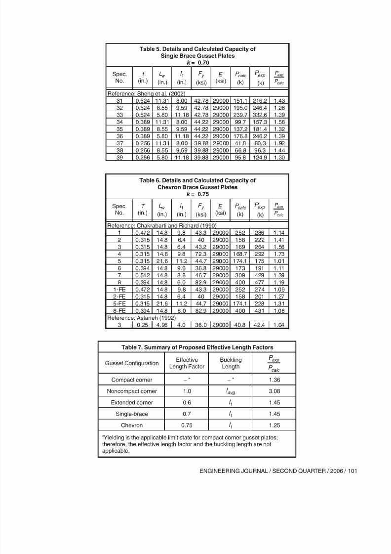
The results for single braces are summarized in Table 5.
There was only one project with nine finite element models.
Using a buckling length, l1 and an effective length factor of
0.70, the mean ratio of experimental load to calculated ca-
pacity, Pexp /Pcalc is 1.45. The standard deviation is 0.20.
The results for chevron braces are summarized in Table 6.
There were two separate projects with a total of 13 speci-
mens—nine were experimental and four were finite element
models. Using a buckling length, l1 and an effective length
factor of 0.75, the mean ratio of experimental load to cal-
culated capacity, Pexp /Pcalc is 1.25. The standard deviation is0.22.
CONCLUSION
Using the experimental and finite element data from the pre-
vious studies, the capacity of gusset plates in compression
were compared with the current design procedures. Based on
a statistical analysis, effective length factors were proposed
for use with the design procedures. Table 7 summarizes the
proposed effective length factors.
It was determined that compact corner gusset plates can
be designed without consideration of buckling effects, and
yielding at the effective width is an accurate predictor oftheir compressive capacity. Due to the high variability of
the test-to-predicted ratios for the noncompact corner gusset
plates, an effective length factor was proposed that was con-
servative for most of the specimens. For the extended corner
gusset plates, the single brace gusset plates, and the chevron
brace gusset plates, effective length factors were proposed
that resulted in reasonably accurate capacities when com-
pared with the test and finite element capacities.
REFERENCES
AISC (2001), Manual of Steel Construction, Load and Re-
sistance Factor Design, Third Edition, American Instituteof Steel Construction, Inc., Chicago, IL.
AISC (1999), Load and Resistance Factor Design Specifica-
tion for Structural Steel Buildings, American Institute of
Steel Construction, Inc., Chicago, IL.
AISC (1995), Manual of Steel Construction, Load and Re-
sistance Factor Design, Volume II , Connections, Ameri-
can Institute of Steel Construction, Chicago, IL.
Astaneh, A. (1992), “Cyclic Behavior of Gusset Plate
Connections in V-Braced Steel Frames,” Stability and
Ductility of Steel Structures Under Cyclic Loading, Y.
Fukomoto and G.C. Lee, editors, CRC Press, Ann Arbor,
MI, pp. 63–84.
ASTM (2004), “Standard Specification for General Require-
ments for Rolled Structural Steel Bars, Plates, Shapes,and Sheet Piling,” ASTM A6, ASTM International, West
Conshohocken, PA.
Bjorhovde, R. and Chakrabarti, S.K. (1985), “Tests of Full-
Size Gusset Plate Connections,” Journal of Structural En-
gineering, ASCE, Vol. 111, No. 3, March, pp. 667–683.
Brown, V.L. (1988), “Stability of Gusseted Connections in
Steel Structures,” Ph.D. Dissertation, University of Delaware.
Chakrabarti, S.K. and Richard, R.M. (1990), “Inelastic
Buckling of Gusset Plates,” Structural Engineering Re-
view, Vol. 2, pp. 13–29.
Chakrabarti, S.K. (1987), Inelastic Buckling of Gusset
Plates, Ph.D. Dissertation, University of Arizona.
Cheng, J.J.R. and Grondin, G.Y. (1999), “Recent Develop-
ment in the Behavior of Cyclically Loaded Gusset Plate
Connections,” Proceedings, 1999 North American Steel
Construction Conference, American Institute of Steel
Construction, Chicago, IL.
Cheng, J.J.R. and Hu, S.Z. (1987), “Comprehensive Tests
of Gusset Plate Connections,” Proceedings, 1987 Annual
Technical Session, Structural Stability Research Council,
pp. 191–205.
Dowswell, B. (2005), Design of Steel Gusset Plates with
Large Cutouts, Ph.D. Dissertation, University of Alabama
at Birmingham.
Fisher, J.W., Galambos, T.V., Kulak, G.L., and Ravindra,
M.K. (1978), “Load and Resistance Factor Design Cri-
teria for Connectors,” Journal of the Structural Division,
ASCE, Vol. 104, No. ST9, September, pp. 1427–1441.
Fouad, F.H., Davidson, J.S., Delatte, N., Calvert, E.A.,
Chen, S., Nunez, E., and Abdalla, R. (2003), “Structur-
al Supports for Highway Signs, Luminaries, and Traffic
Signals,” NCHRP Report 494, Transportation Research
Board, Washington, DC.
Gross, J.L. and Cheok, G. (1988), “Experimental Study of
Gusseted Connections for Laterally Braced Steel Build-
ings,” National Institute of Standards and Technology,
Gaithersburg, MD, November.
Irvan, W.G. (1957), “Experimental Study of Primary Stresses
in Gusset Plates of a Double Plane Pratt Truss,” University
of Kentucky, Engineering Research Station Bulletin No.
46, December.
Lavis, C.S. (1967), “Computer Analysis of the Stresses in a
Gusset Plate,” Masters Thesis, University of Washington.
8/21/2019 Gusset Plates
http://slidepdf.com/reader/full/gusset-plates 8/12
98 / ENGINEERING JOURNAL / SECOND QUARTER / 2006
Nast, T.E., Grondin, G.Y., and Cheng, J.J.R. (1999),
“Cyclic Behavior of Stiffened Gusset Plate Brace
Member Assemblies,” Structural Engineering Report
No. 229, University of Alberta, Department of Civil and
Environmental Engineering, December.
Rabinovitch, J. and Cheng, J.J.R. (1993), “Cyclic Behavior
of Steel Gusset Plate Connections,” Structural Engineer-ing Report No. 191, University of Alberta, Department of
Civil and Environmental Engineering, August.
Raburn, D.A. (1983), “Stress, Strain and Force Distributions
in Gusset Plate Connections,” Masters Thesis, University
of Arizona.
Sandel, J.A. (1950), “Photoelastic Analysis of Gusset Plates,”
Masters Thesis, University of Tennessee, December.
Sheng, N., Yam, C.H., and Iu, V.P. (2002), “Analytical In-
vestigation and the Design of the Compressive Strength
of Steel Gusset Plate Connections,” Journal of Construc-
tional Steel Research, Vol. 58, pp. 1473–1493.
Thornton, W.A. (1984), “Bracing Connections for Heavy
Construction,” Engineering Journal, American Institute
of Steel Construction, 3rd Quarter, pp. 139–148.
Timoshenko, S. and Woinowsky-Krieger, S. (1959), Theory
of Plates and Shells, 2nd edition, McGraw-Hill, New
York.
Walbridge, S.S., Grondin, G.Y., and Cheng, J.J.R. (1998),
“An Analysis of the Cyclic Behavior of Steel Gusset Plate
Connections,” Structural Engineering Report No. 225,
University of Alberta, Department of Civil and Environ-mental Engineering, September.
Whitmore, R.E. (1952), “Experimental Investigation of
Stresses in Gusset Plates,” Bulletin No. 16, University of
Tennessee Engineering Experiment Station, May.
Wyss, T. (1926), “Die Kraftfelder in Festen Elastischen Kor-
pern und ihre Praktischen Anwendungen,” Berlin.
Yam, M.C.H. and Cheng, J.J.R. (1993), “Experimental In-
vestigation of the Compressive Behavior of Gusset Plate
Connections,” University of Alberta Department of Civil
Engineering Structural Engineering Report No. 194, Sep-
tember.
Yamamoto, K., Akiyama, N., and Okumura, T. (1988),
“Buckling Strengths of Gusseted Truss Joints,” Journal of
Structural Engineering, ASCE, Vol. 114, No. 3, March,
pp. 575-591.
8/21/2019 Gusset Plates
http://slidepdf.com/reader/full/gusset-plates 9/12
ENGINEERING JOURNAL / SECOND QUARTER / 2006 / 99
TABLES
Table 1. Summary of Current Effective Length Factors
Gusset ConfigurationEffective
Length FactorBucklingLength
P
P calc
exp
Compact corner 0.5 avg l 1.47
Noncompact corner 0.5 avg l 0.98Single brace 1.2 1l 2.40
Table 2. Details and Calculated Capacity ofCompact Corner Gusset Plates
Full Yield Capacity
Spec.No.
t
(in.)L
w
(in.)F
y
(ksi)P
calc
(k)P
exp
(k)
P
P calc
exp
Reference: Chakrabarti (1987)
1 0.25 7.62 36 68.6 68.7 1.002 0.25 7.62 36 68.6 70.3 1.03
3 0.25 7.62 36 68.6 71.4 1.04
Reference: Gross and Cheok (1988)
1A 0.25 7.62 46.7 89.0 116 1.30
1B 0.25 7.62 46.7 89.0 96 1.08
2A 0.25 7.62 46.7 89.0 138 1.55
2B 0.25 7.62 46.7 89.0 148 1.66
3B 0.25 7.62 46.7 89.0 88 0.99
Reference: Brown (1988)
1 0.251 9.2 48 110.8 180 1.62
2 0.196 8.66 45.2 76.7 120 1.56
3 0.198 9.2 45.2 82.3 82 1.00
9 0.192 8.66 45.2 75.2 79.6 1.06
10 0.197 8.66 45.2 77.1 109.5 1.42
11 0.25 9.2 48 110.4 165.9 1.50
13 0.248 9.2 48 109.5 139.4 1.27
14 0.248 8.66 48 103.1 134.6 1.31
15 0.25 9.2 48 110.4 154.2 1.40
16 0.25 8.66 48 103.9 147.1 1.42
17 0.194 9.2 45.2 80.7 120 1.49
18 0.251 8.66 48 104.3 154.5 1.48
20 0.376 8.66 45 146.5 176.1 1.20
Reference: Sheng et al. (2002)
1 0.524 9.04 42.75 202.7 365.9 1.80
2 0.524 12.22 42.75 274.1 447.1 1.63
3 0.524 15.41 42.75 345.5 528.5 1.53
4 0.524 9.04 42.75 202.7 358.9 1.77
5 0.524 12.22 42.75 274.1 438.5 1.60
6 0.524 15.41 42.75 345.5 525.4 1.52
7 0.389 9.04 44.20 155.6 257.2 1.65
8 0.389 12.22 44.20 210.3 322.2 1.539 0.389 15.41 44.20 265.1 420.1 1.58
10 0.389 9.04 44.20 155.6 252.5 1.62
11 0.389 12.22 44.20 210.3 315.5 1.50
12 0.389 15.41 44.20 265.2 408.2 1.54
13 0.256 9.04 39.86 92.4 114.5 1.24
14 0.256 12.22 39.86 124.9 156.6 1.25
15 0.256 15.41 39.86 157.4 222.5 1.41
16 0.256 9.04 39.86 92.4 112.1 1.21
17 0.256 12.22 39.86 124.9 149.9 1.20
18 0.256 15.41 39.86 157.4 207.0 1.32
Table 2 (continued).Details and Calculated Capacity of
Compact Corner Gusset PlatesFull Yield Capacity
Spec.No.
t
(in.)L
w
(in.)F
y
(ksi)P
calc
(k)P
exp
(k)
P
P calc
exp
Reference: Yam and Cheng (1993)
GP1 0.524 12.22 42.75 274.0 440.1 1.61
GP2 0.386 12.22 44.20 208.8 305.1 1.46
GP3 0.256 12.22 39.86 124.8 167.0 1.34
GP1R 0.524 12.22 42.75 274.0 462.8 1.69
GP2R 0.386 12.22 44.20 208.8 334.6 1.60
GP3R 0.256 12.22 39.86 124.8 177.8 1.42
AP1 0.524 12.22 42.75 274.0 387.0 1.41
AP2 0.386 12.22 44.20 208.8 272.3 1.30
AP3 0.256 12.22 39.86 124.8 163.8 1.31
MP1 0.524 12.22 42.75 274.0 434.9 1.59
MP2 0.386 12.22 44.20 208.8 296.1 1.42
MP3 0.256 12.22 39.86 124.8 162.2 1.30
MP3A 0.256 12.22 39.86 124.8 184.3 1.48
MP3B 0.256 12.22 39.86 124.8 184.7 1.48
Reference: Rabinovitch and Cheng (1993)A1 0.367 15.49 65.07 370.3 378.5 1.02
A2 0.243 15.49 64.20 242.3 253.8 1.05
A3 0.367 15.49 65.07 370.3 450.9 1.22
A4 0.243 15.49 64.20 242.3 258.5 1.07
Reference: Nast et al. (1999)
T2-FE 0.378 15.49 61.45 360.6 444.2 1.23
T2 0.378 15.49 61.45 360.6 380.3 1.05
Reference: Walbridge et al. (1998)
GP1B1 0.236 15.49 43.48 159.3 154.8 0.97
GP1B3 0.236 15.49 43.48 159.3 155.7 0.98
GP2B7 0.354 15.49 43.48 238.9 290.7 1.22
GP3B11 0.472 15.49 43.48 318.6 403.4 1.27
GP1MC 0.524 12.22 42.75 274.0 466.4 1.70
GP2MC 0.386 12.22 44.20 208.8 302.0 1.45
GP3MC 0.256 12.22 39.86 124.8 160.0 1.28A2CL2 0.243 15.49 64.20 242.3 246.2 1.02
A4CL4 0.243 15.49 64.20 242.3 252.0 1.04
8/21/2019 Gusset Plates
http://slidepdf.com/reader/full/gusset-plates 10/12
100 / ENGINEERING JOURNAL / SECOND QUARTER / 2006
Table 3. Details and Calculated Capacity ofNoncompact Corner Gusset Plates
k = 1.0
Spec.No.
t (in.)
w L
(in.)
avg l
(in.)
y F
(ksi)
E (ksi)
calc P
(k)
P exp
(k)
P
P calc
exp
Reference: Cheng and Hu (1987)
C1-Free 0.264 22.36 8.94 73.19 30595 113.5 99.4 0.875
C2-Free 0.122 22.36 8.94 34.78 28565 10.6 27.5 2.60
C3-Free 0.264 22.36 14.50 73.19 30595 43.1 85.5 1.98
C4-Free 0.122 22.36 14.50 34.78 28565 4.0 20.2 5.01
C1-Fixed 0.264 22.36 8.94 73.19 30595 113.5 205.7 1.81
C2-Fixed 0.122 22.36 8.94 34.78 28565 10.6 31.6 2.98
C3-Fixed 0.264 22.36 14.50 73.19 30595 43.1 152.6 3.54
C4-Fixed 0.122 22.36 14.50 34.78 28565 4.0 32.7 8.13
Reference: Yam and Cheng (1993)
SP1-Free 0.524 18.59 16.33 42.75 30102 206.2 361.4 1.75
SP2-Free 0.386 18.59 16.33 44.20 30479 88.1 227.3 2.58
SP1-Fix 0.524 18.59 16.33 42.75 30102 206.2 396.0 1.92
SP2-Fix 0.386 18.59 16.33 44.20 30479 88.1 332.3 3.77
Table 4. Details and Calculated Capacity ofExtended Corner Gusset Plates
k = 0.60
Spec.
No.
t
(in.)
w L
(in.)
1l
(in.)
y F
(ksi)
E
(ksi)
calc P
(k)
P exp
(k)
P
P calc
exp
Reference: Sheng et al. (2002)
19 0.524 9.04 11.31 42.75 29000 178.7 333.0 1.86
20 0.524 12.22 8.55 42.75 29000 255.0 403.4 1.58
21 0.524 15.41 5.80 42.75 29000 334.2 496.8 1.49
22 0.524 9.04 11.31 42.75 29000 178.7 277.2 1.55
23 0.524 12.22 8.55 42.75 29000 255.0 335.3 1.31
24 0.524 15.14 5.80 42.75 29000 328.3 463.7 1.41
25 0.389 9.04 11.31 44.20 29000 122.8 197.6 1.61
26 0.389 12.22 8.55 44.20 29000 183.7 243.5 1.33
27 0.389 15.14 5.80 44.20 29000 244.7 327.2 1.34
28 0.256 9.04 11.31 39.86 29000 56.5 90.9 1.61
29 0.256 12.22 8.55 39.86 29000 94.2 126.0 1.34
30 0.256 15.14 5.80 39.86 29000 135.9 172.1 1.27Reference: Rabinovitch and Cheng (1993)
A5 0.367 15.49 15.20 65.07 29870 186.6 204.1 1.09
8/21/2019 Gusset Plates
http://slidepdf.com/reader/full/gusset-plates 11/12
ENGINEERING JOURNAL / SECOND QUARTER / 2006 / 101
Table 6. Details and Calculated Capacity ofChevron Brace Gusset Plates
k = 0.75
Spec.No.
T (in.)
w L
(in.)
1l
(in.)
y F
(ksi)
E (ksi)
calc P
(k)
P exp
(k)
P
P calc
exp
Reference: Chakrabarti and Richard (1990)
1 0.472 14.8 9.8 43.3 29000 252 286 1.14
2 0.315 14.8 6.4 40 29000 158 222 1.41
3 0.315 14.8 6.4 43.2 29000 169 264 1.56
4 0.315 14.8 9.8 72.3 29000 168.7 292 1.73
5 0.315 21.6 11.2 44.7 29000 174.1 175 1.01
6 0.394 14.8 9.6 36.8 29000 173 191 1.11
7 0.512 14.8 8.8 46.7 29000 309 429 1.39
8 0.394 14.8 6.0 82.9 29000 400 477 1.19
1-FE 0.472 14.8 9.8 43.3 29000 252 274 1.092-FE 0.315 14.8 6.4 40 29000 158 201 1.27
5-FE 0.315 21.6 11.2 44.7 29000 174.1 228 1.31
8-FE 0.394 14.8 6.0 82.9 29000 400 431 1.08
Reference: Astaneh (1992)
3 0.25 4.96 4.0 36.0 29000 40.8 42.4 1.04
Table 7. Summary of Proposed Effective Length Factors
Gusset ConfigurationEffective
Length FactorBucklingLength
P
P calc
exp
Compact corner �
a�
a 1.36
Noncompact corner 1.0 avg l 3.08
Extended corner 0.6 1l 1.45
Single-brace 0.7 1l 1.45
Chevron 0.75 1l 1.25
aYielding is the applicable limit state for compact corner gusset plates;therefore, the effective length factor and the buckling length are notapplicable.
Table 5. Details and Calculated Capacity ofSingle Brace Gusset Plates
k = 0.70
Spec.No.
t (in.)
w L
(in.)
1l
(in.)
y F
(ksi)
E (ksi)
calc P
(k)
P exp
(k)
P
P calc
exp
Reference: Sheng et al. (2002)
31 0.524 11.31 8.00 42.78 29000 151.1 216.2 1.43
32 0.524 8.55 9.59 42.78 29000 195.0 246.4 1.26
33 0.524 5.80 11.18 42.78 29000 239.7 332.6 1.39
34 0.389 11.31 8.00 44.22 29000 99.7 157.3 1.58
35 0.389 8.55 9.59 44.22 29000 137.2 181.4 1.32
36 0.389 5.80 11.18 44.22 29000 176.8 246.2 1.39
37 0.256 11.31 8.00 39.88 29000 41.8 80.3 1.92
38 0.256 8.55 9.59 39.88 29000 66.8 96.3 1.44
39 0.256 5.80 11.18 39.88 29000 95.8 124.9 1.30

8/21/2019 Gusset Plates
http://slidepdf.com/reader/full/gusset-plates 12/12