Embed Size (px)
Citation preview
U.S. Department Publication No. FHWA-xxx-09-xxx of Transportation February 2009 Federal Highway Administration
Load Rating Guidance and Examples For Bolted and Riveted Gusset Plates
In Truss Bridges
by
Firas I. Sheikh Ibrahim, PhD, PE
Table of Contents
I - Load Rating Guidance.................................................................................................... 1 Part – A: Gusset Plate Resistance in Accordance with the Load and Resistance Factor Rating Method (LRFR) ....................................................................................................... 1
1. General: ................................................................................................................... 12. Resistance of Fasteners ........................................................................................... 13. Resistance of Gusset Plates..................................................................................... 2
3.1. Gusset Plates in Tension ................................................................................. 33.1.1. Gross Section Yielding Resistance ......................................................... 33.1.2. Net Section Fracture Resistance ............................................................. 33.1.3. Block Shear Rupture Resistance ............................................................. 5
3.2. Gusset Plates Subject to Shear ........................................................................ 63.3. Gusset Plates in Compression......................................................................... 73.4. Gusset Plates Under Combined Flexural and Axial Loads............................. 93.5. Limiting Slenderness Ratio ............................................................................. 9
Part – B: Gusset Plate Resistance in Accordance with the Load Factor Rating Method (LFR)................................................................................................................................. 10
1. General .................................................................................................................. 102. Resistance of Fasteners ......................................................................................... 103. Resistance of Gusset Plates................................................................................... 11
3.1. Gusset Plates in Tension ............................................................................... 113.1.1. Effective Gross Section Yielding.......................................................... 113.1.2. Block Shear Rupture Resistance ........................................................... 13
3.2. Gusset Plates Subject to Shear ...................................................................... 143.3. Gusset Plates in Compression....................................................................... 163.4. Gusset Plates Under Combined Flexural and Axial Loads........................... 173.5. Limiting Slenderness Ratio ........................................................................... 17
II - Load Rating Examples ................................................................................................ 18 Part – A: Gusset Plate Load Rating Example in Accordance with the Load and Resistance Factor Rating Method (LRFR) ....................................................................... 18
1. Resistance of Fasteners ......................................................................................... 181.1. Fasteners at End of Members 1 and 5 ........................................................... 18
1.1.1. Shear Resistance of Fasteners ............................................................... 181.1.2. Plate Bearing Resistance at Fasteners ................................................... 19
1.2. Fasteners at End of Member 2 ...................................................................... 191.2.1. Shear Resistance of Fasteners ............................................................... 191.2.2. Plate Bearing Resistance at Fasteners ................................................... 19
1.3. Fasteners at End of Member 3 ...................................................................... 20
i
1.3.1. Shear Resistance of Fasteners ............................................................... 201.3.2. Plate Bearing Resistance at Fasteners ................................................... 20
1.4. Fasteners at End of Member 4 ...................................................................... 201.4.1. Shear Resistance of Fasteners ............................................................... 201.4.2. Plate Bearing Resistance at Fasteners ................................................... 20
2. Resistance of Gusset Plate .................................................................................... 212.1. Gusset Plate in Tension at Members 1 and 5 ................................................ 21
2.1.1. Gross Section Yielding Resistance ....................................................... 212.1.2. Net Section Fracture Resistance ........................................................... 212.1.3. Block Shear Rupture Resistance ........................................................... 22
2.2. Gusset Plate in Tension at Member 2 ........................................................... 222.2.1. Gross Section Yielding Resistance ....................................................... 222.2.2. Net Section Fracture Resistance ........................................................... 232.2.3. Block Shear Rupture Resistance ........................................................... 24
2.3. Gusset Plate Subject to Vertical Shear.......................................................... 252.3.1. Gross Section Shear Yielding Resistance ............................................. 252.3.2. Net Section Shear Fracture Resistance ................................................. 25
2.4. Gusset Plate Subject to Horizontal Shear ..................................................... 262.4.1. Gross Section Shear Yielding Resistance ............................................. 262.4.2. Net Section Shear Fracture Resistance ................................................. 27
2.5. Gusset Plate in Compression at Member 3 ................................................... 272.6. Gusset Plate in Compression at Member 4 ................................................... 29
3. Resistance Summary............................................................................................. 304. Inventory and Operating Rating Factors ............................................................... 31
Part – B: Gusset Plate Load Rating Example in Accordance with the Load Factor Rating Method (LFR) ................................................................................................................... 32
1. Resistance of Fasteners ......................................................................................... 321.1. Fasteners at End of Members 1 and 5 ........................................................... 32
1.1.1. Shear Resistance of Fasteners ............................................................... 321.1.2. Plate Bearing Resistance at Fasteners ................................................... 33
1.2. Fasteners at End of Member 2 ...................................................................... 331.2.1. Shear Resistance of Fasteners ............................................................... 331.2.2. Plate Bearing Resistance at Fasteners ................................................... 33
1.3. Fasteners at End of Member 3 ...................................................................... 341.3.1. Shear Resistance of Fasteners ............................................................... 341.3.2. Plate Bearing Resistance at Fasteners ................................................... 34
1.4. Fasteners at End of Member 4 ...................................................................... 341.4.1. Shear Resistance of Fasteners ............................................................... 341.4.2. Plate Bearing Resistance at Fasteners ................................................... 35
2. Resistance of Gusset Plate .................................................................................... 352.1. Gusset Plate in Tension at Members 1 and 5 ................................................ 35
2.1.1. Gross Section Yielding Resistance ....................................................... 352.1.2. Block Shear Rupture Resistance ........................................................... 36
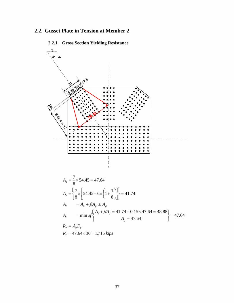
2.2. Gusset Plate in Tension at Member 2 ........................................................... 372.2.1. Gross Section Yielding Resistance ....................................................... 37
ii
2.2.2. Block Shear Rupture Resistance ........................................................... 382.3. Gusset Plate Subject to Vertical Shear.......................................................... 39
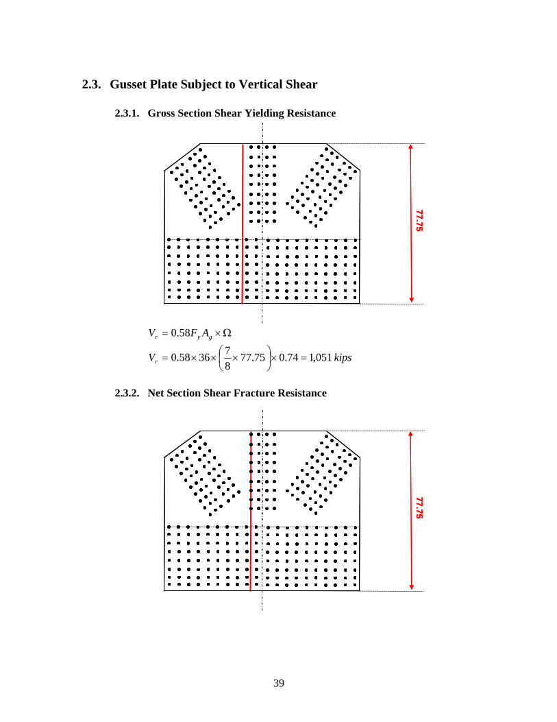
2.3.1. Gross Section Shear Yielding Resistance ............................................. 392.3.2. Net Section Shear Fracture Resistance ................................................. 39
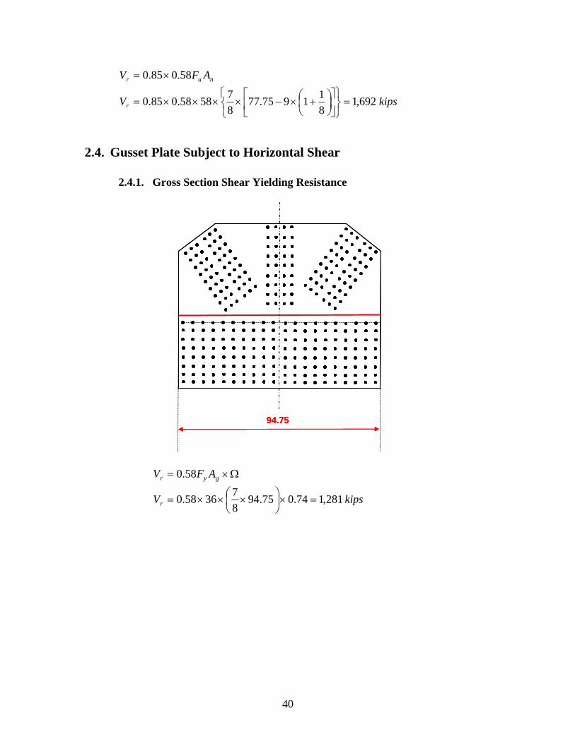
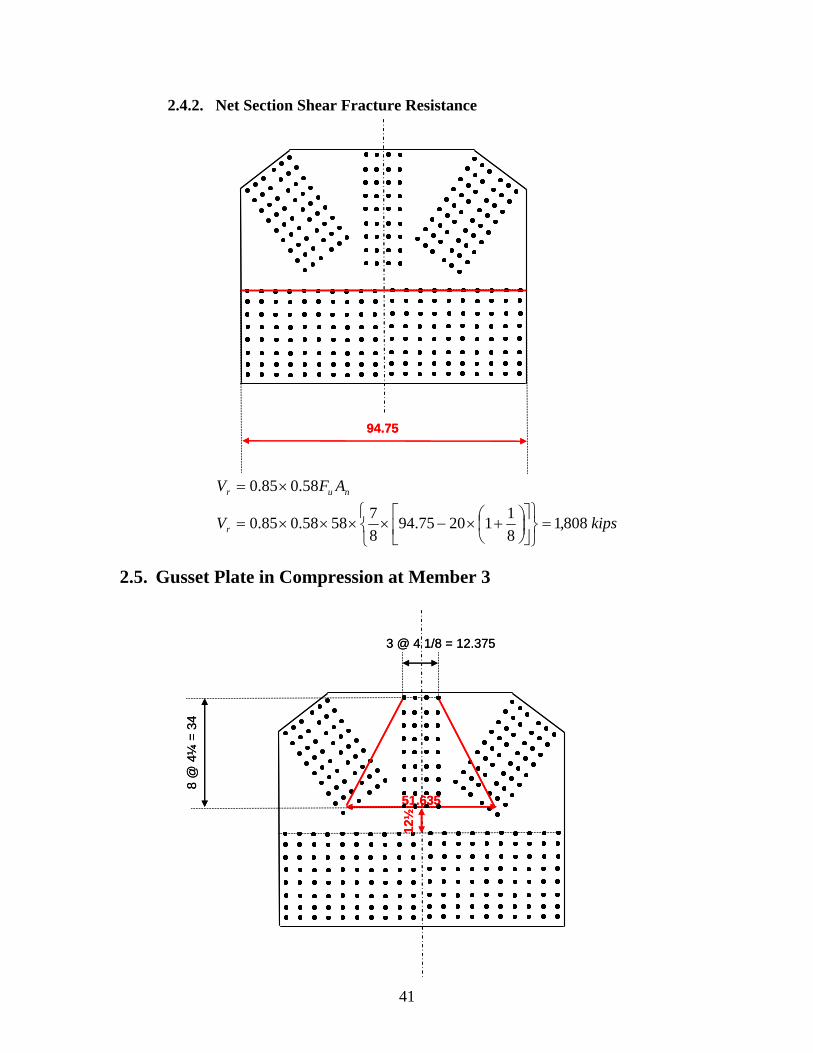
2.4. Gusset Plate Subject to Horizontal Shear ..................................................... 402.4.1. Gross Section Shear Yielding Resistance ............................................. 402.4.2. Net Section Shear Fracture Resistance ................................................. 41
2.5. Gusset Plate in Compression at Member 3 ................................................... 412.6. Gusset Plate in Compression at Member 4 ................................................... 42
3. Resistance Summary............................................................................................. 434. Inventory and Operating Rating Factors ............................................................... 44
iii
Load Rating Guidance and Examples
for Bolted and Riveted Gusset Plates
in Truss Bridges
By Firas I. Sheikh Ibrahim, PhD, PE
Release Date: February 1, 2009
I - Load Rating Guidance
Part – A: Gusset Plate Resistance in Accordance with the Load and Resistance Factor Rating Method (LRFR)
1. General Gusset connections of non-load-path-redundant steel truss bridges shall be evaluated during a bridge load rating analysis. Non-load-path-redundant bridges are those with no alternate load paths and whose failure of a main component is expected to result in the collapse of the bridge The evaluation of gusset connections shall include the evaluation of the connecting plates and fasteners. The resistance of a gusset connection is determined as the smaller resistance of the fasteners or gusset plates. The following guidance is intended to provide for life safety and thus the resistance of the connection is required to be checked at the strength limit state only. Owners may require that connections be checked at other limit states such as the service limit state to minimize serviceability concerns.
2. Resistance of Fasteners For concentrically loaded bolted and riveted gusset connections, the axial load in each connected member may be assumed to be distributed equally to all fasteners at the strength limit state.
1
The bolts in bolted gusset connections shall be evaluated to prevent bolt shear and plate bearing failures at the strength limit state. At the strength limit state, the provisions of AASHTO LRFD Articles 6.13.2.7 and 6.13.2.9 shall apply for determining the resistance of bolts to prevent bolt shear and plate bearing failures. The rivets in riveted gusset connections shall be evaluated to prevent rivet shear and plate bearing failures at the strength limit state. The plate bearing resistance for riveted connections shall be in accordance with AASHTO LRFD Article 6.13.2.9 for bearing at bolt holes. The factored shear resistance of one rivet shall be taken as:
rFmAR (1) where:
F = Factored shear strength of one rivet. The values in Table 1 may be used for F based on the year of construction for unknown rivet types, or on the type of rivets.
Table 1
Year of Construction F ksi
Constructed prior to 1936 or of unknown origin
18
Constructed after 1936 but of unknown origin
21
ASTM A 502 Grade I 27
ASTM A 502 Grade II 32
m = the number of shear planes Ar = cross-sectional area of the rivet before driving The shear resistance of a rivet in connections greater than 50.0 in. in length shall be taken as 0.80 times the value given in Eq. 1. The length of the connection is measured between the extreme fasteners on one side of the connection.
3. Resistance of Gusset Plates The resistance of a gusset plate shall be determined as the least resistance of the plate in compression, shear, and tension including block shear.
2
3.1. Gusset Plates in Tension Gusset plates subjected to axial tension shall be investigated for three conditions:
• Yield on the gross section, • Fracture on the net section, and • Block shear rupture
The factored resistance, Pr, for gusset plates in tension shall be taken as the least of the values given by yielding, fracture, or the block shear rupture resistance.
3.1.1. Gross Section Yielding Resistance
gyynyyr AFPP (2)
3.1.2. Net Section Fracture Resistance
UAFPP nuunuur (3)
where:
y = resistance factor for tension yielding = 0.95
u = resistance factor for tension fracture = 0.80
Pny = nominal tensile resistance for yielding in gross section An = net cross-sectional area of the plates as specified in AASHTO LRFD Article
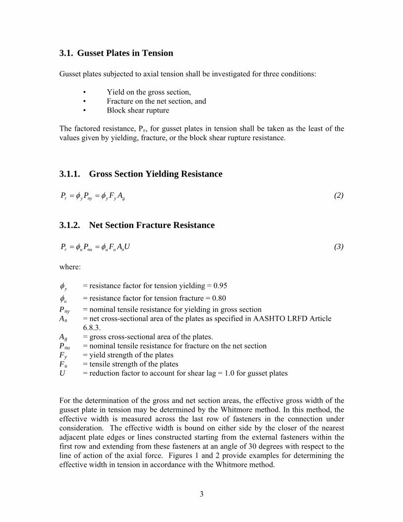
6.8.3. Ag = gross cross-sectional area of the plates. Pnu = nominal tensile resistance for fracture on the net section Fy = yield strength of the plates Fu = tensile strength of the plates U = reduction factor to account for shear lag = 1.0 for gusset plates For the determination of the gross and net section areas, the effective gross width of the gusset plate in tension may be determined by the Whitmore method. In this method, the effective width is measured across the last row of fasteners in the connection under consideration. The effective width is bound on either side by the closer of the nearest adjacent plate edges or lines constructed starting from the external fasteners within the first row and extending from these fasteners at an angle of 30 degrees with respect to the line of action of the axial force. Figures 1 and 2 provide examples for determining the effective width in tension in accordance with the Whitmore method.
3
Figure 1 – Example 1 for using the Whitmore method to determine the effective
width in tension
Figure 2 – Example 2 for using the Whitmore method to determine the effective
width in tension
4
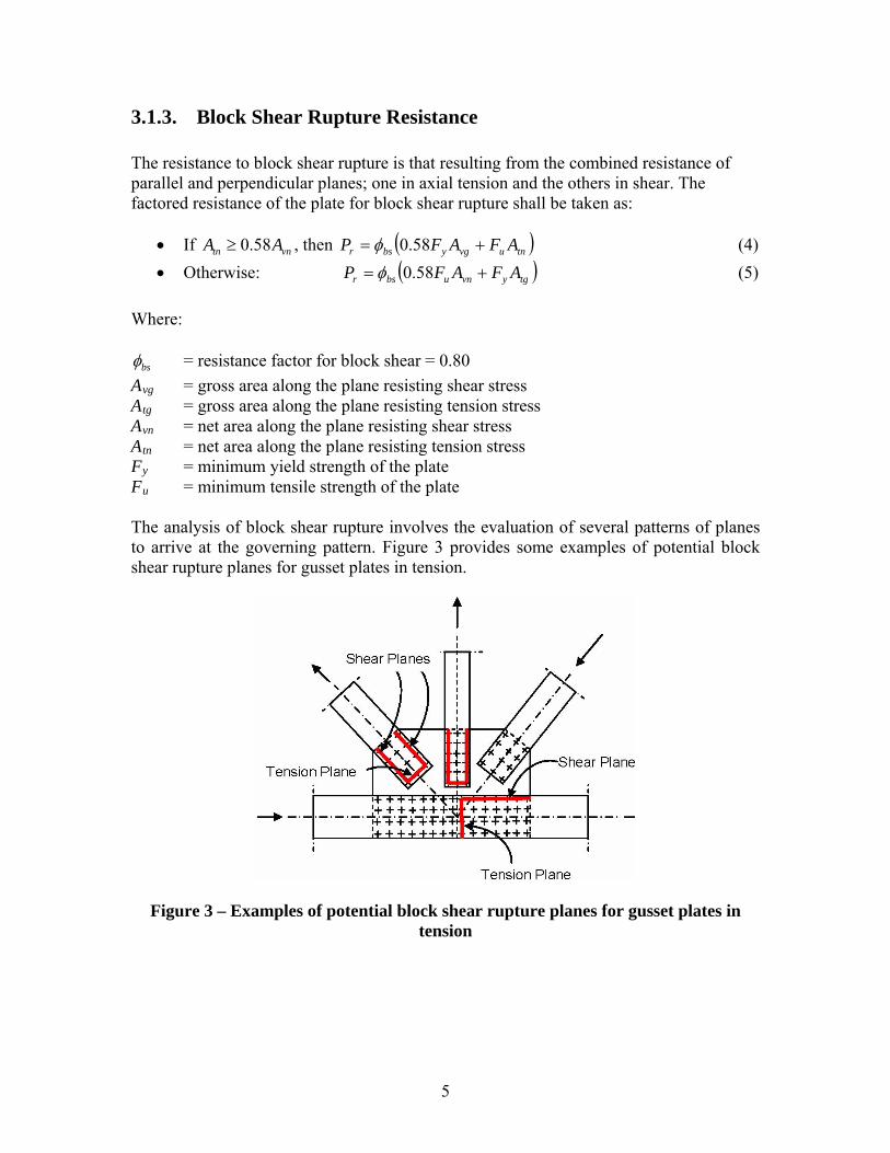
3.1.3. Block Shear Rupture Resistance The resistance to block shear rupture is that resulting from the combined resistance of parallel and perpendicular planes; one in axial tension and the others in shear. The factored resistance of the plate for block shear rupture shall be taken as:
If vn , then tn AA 58.0 tnuvgybsr AFAFP 58.0 (4)
Otherwise: tgyvnubsr AFAFP 58.0 (5)
Where:
bs = resistance factor for block shear = 0.80
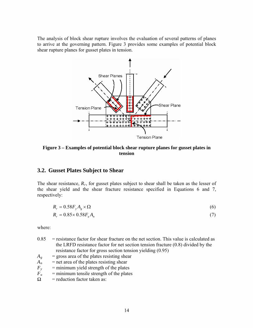
Avg = gross area along the plane resisting shear stress Atg = gross area along the plane resisting tension stress Avn = net area along the plane resisting shear stress Atn = net area along the plane resisting tension stress Fy = minimum yield strength of the plate Fu = minimum tensile strength of the plate The analysis of block shear rupture involves the evaluation of several patterns of planes to arrive at the governing pattern. Figure 3 provides some examples of potential block shear rupture planes for gusset plates in tension.
Figure 3 – Examples of potential block shear rupture planes for gusset plates in tension
5
3.2. Gusset Plates Subject to Shear The factored shear resistance, Vr, for gusset plates subject to shear shall be taken as the lesser of the shear yield and the shear fracture resistance specified in Equations 6 and 7, respectively:
gyvynvyr AFVV 58.0 (6)
nuvunvur AFVV 58.0 (7)
where:
vy = resistance factor for shear yielding on the gross section = 0.95
vu = resistance factor for shear fracture on the net section = 0.80
Vn = nominal resistance in shear Ag = gross area of the plates resisting shear An = net area of the plates resisting shear Fy = minimum yield strength of the plates Fu = minimum tensile strength of the plates Ω = reduction factor taken as:
• Ω = 1.00 when the gusset plates are of ample stiffness to prevent buckling and develop the plastic shear force of the plates, or
• Ω = 0.74 in the absence of a more rigorous analysis or criterion to assure and quantify the stiffness requirements to develop the plastic shear force of the plates.
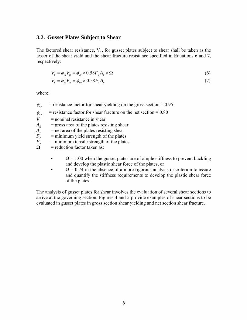
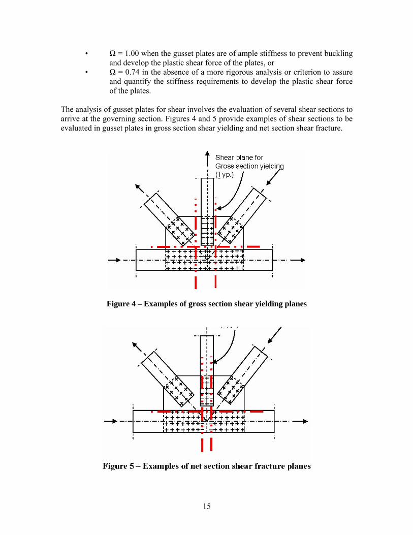
The analysis of gusset plates for shear involves the evaluation of several shear sections to arrive at the governing section. Figures 4 and 5 provide examples of shear sections to be evaluated in gusset plates in gross section shear yielding and net section shear fracture.
6
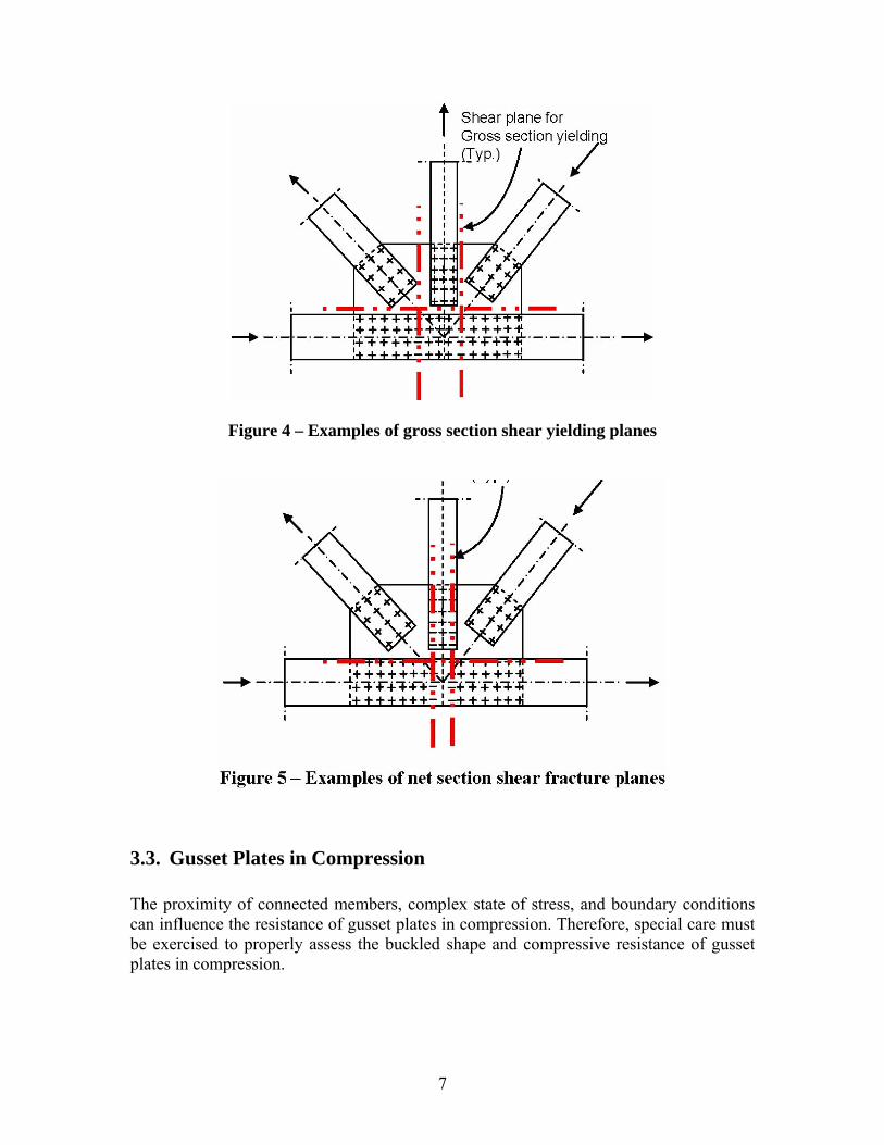
Figure 4 – Examples of gross section shear yielding planes
3.3. Gusset Plates in Compression The proximity of connected members, complex state of stress, and boundary conditions can influence the resistance of gusset plates in compression. Therefore, special care must be exercised to properly assess the buckled shape and compressive resistance of gusset plates in compression.
7
In the absence of a more rigorous analysis, the resistance of gusset plates in compression may be determined as that of idealized members in compression, in accordance with the provisions of AASHTO LRFD Articles 6.9.2.1 and 6.9.4. The effective width of the idealized compression member may be determined in accordance with the Whitmore method. The unbraced length, Lc, may be determined as the average of three distances (L1, L2, L3) as follows: where: L2 = The distance from the last row of fasteners in the compression member under
consideration to the first row of fasteners in the closest adjacent member, measured along the line of action of the compressive axial force.
L1, L3 = The distance from each of the ends of the Whitmore width to the first row of
fasteners in the closest adjacent member, measured parallel to the line of action of the compressive axial force. When the Whitmore width enters into the adjacent member, the associated distance at that end should be set to zero.
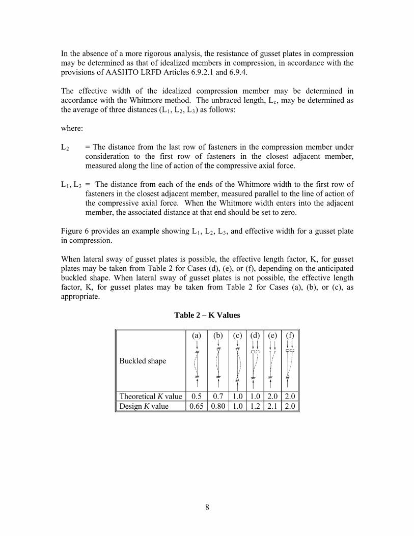
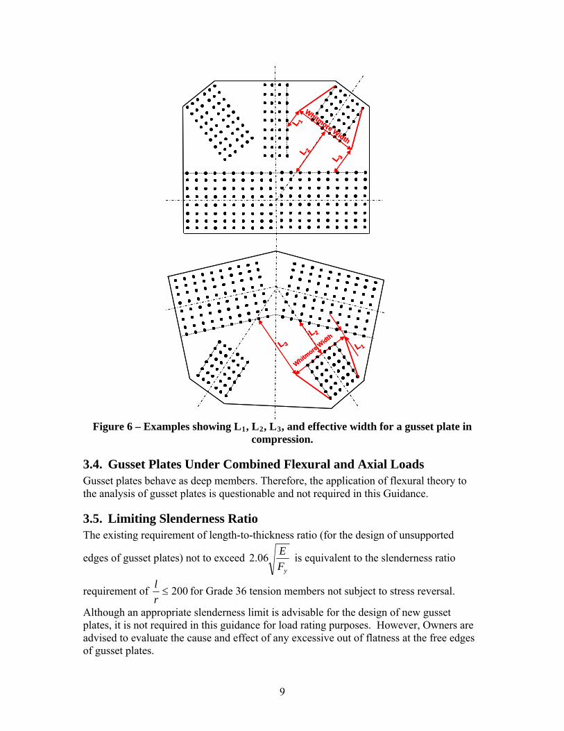
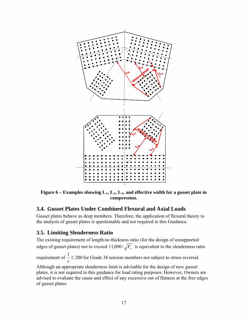
Figure 6 provides an example showing L1, L2, L3, and effective width for a gusset plate in compression. When lateral sway of gusset plates is possible, the effective length factor, K, for gusset plates may be taken from Table 2 for Cases (d), (e), or (f), depending on the anticipated buckled shape. When lateral sway of gusset plates is not possible, the effective length factor, K, for gusset plates may be taken from Table 2 for Cases (a), (b), or (c), as appropriate.
Table 2 – K Values
Buckled shape
(a)
(b)
(c)
(d) (e) (f)
Theoretical K value 0.5 0.7 1.0 1.0 2.0 2.0 Design K value 0.65 0.80 1.0 1.2 2.1 2.0
8
L 2
Whitmore Width
L 3
L 1
Figure 6 – Examples showing L1, L2, L3, and effective width for a gusset plate in compression.
L 2
Whitmore Width
L 3
L 1
Whitm
ore W
idth
L 2
L 3 L 1
Whitm
ore W
idth
L 2
L 3 L 1
3.4. Gusset Plates Under Combined Flexural and Axial Loads Gusset plates behave as deep members. Therefore, the application of flexural theory to the analysis of gusset plates is questionable and not required in this Guidance.
3.5. Limiting Slenderness Ratio The existing requirement of length-to-thickness ratio (for the design of unsupported
edges of gusset plates) not to exceed yF
E06.2 is equivalent to the slenderness ratio
requirement of 200r
lfor Grade 36 tension members not subject to stress reversal.
Although an appropriate slenderness limit is advisable for the design of new gusset plates, it is not required in this guidance for load rating purposes. However, Owners are advised to evaluate the cause and effect of any excessive out of flatness at the free edges of gusset plates.
9
Part – B: Gusset Plate Resistance in Accordance with the Load Factor Rating Method (LFR)
1. General Gusset connections of non-load-path-redundant steel truss bridges shall be evaluated during a bridge load rating analysis. Non-load-path-redundant bridges are those with no alternate load paths and whose failure of a main component is expected to result in the collapse of the bridge. The evaluation of gusset connections shall include the evaluation of the connecting plates and fasteners. The capacity (referred to as the resistance in this Guidance) of a gusset connection is determined as the smaller resistance of the fasteners or gusset plates. The following guidance is intended to provide for life safety and thus the resistance of the connection is required to be checked at maximum loads only. The maximum loads are the loadings specified in AASHTO Article 10.47. Owners may require that connections be checked for other loading levels such as overload to minimize serviceability concerns.
2. Resistance of Fasteners For concentrically loaded bolted and riveted gusset connections, the maximum axial load in each connected member may be assumed to be distributed equally to all fasteners. At maximum loads, the fasteners in bolted and riveted gusset connections shall be evaluated to prevent fastener shear and plate bearing failures. The provisions of AASHTO Article 10.56.1.3.2 shall apply for determining the resistance of fasteners to prevent fastener shear and plate bearing failures. For unknown rivet types, the shear resistance of one rivet shall be taken as:
rFmAR (1) where:
F = shear strength of one rivet. The values in Table 1 may be used for F based on the year of construction:
10
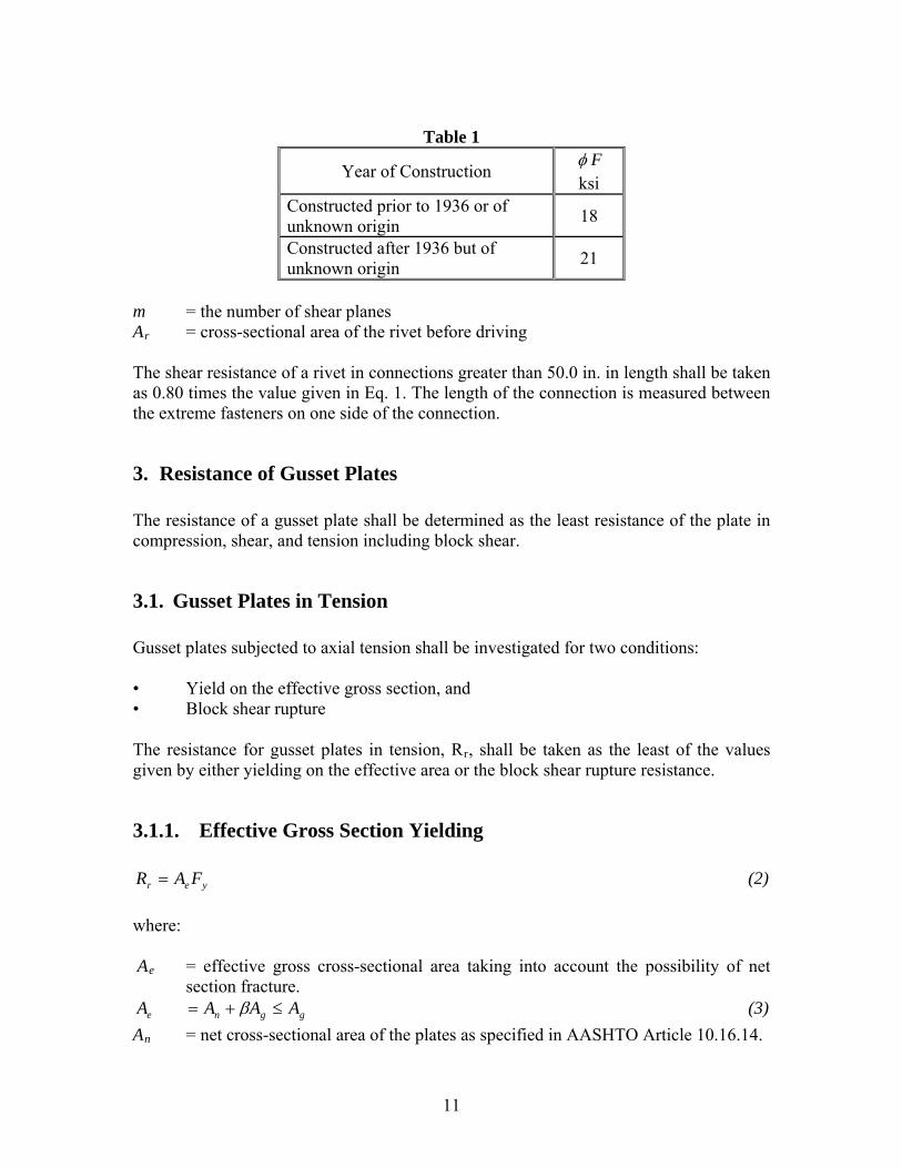
Table 1
Year of Construction F ksi
Constructed prior to 1936 or of unknown origin
18
Constructed after 1936 but of unknown origin
21
m = the number of shear planes Ar = cross-sectional area of the rivet before driving The shear resistance of a rivet in connections greater than 50.0 in. in length shall be taken as 0.80 times the value given in Eq. 1. The length of the connection is measured between the extreme fasteners on one side of the connection.
3. Resistance of Gusset Plates The resistance of a gusset plate shall be determined as the least resistance of the plate in compression, shear, and tension including block shear.
3.1. Gusset Plates in Tension Gusset plates subjected to axial tension shall be investigated for two conditions: • Yield on the effective gross section, and • Block shear rupture The resistance for gusset plates in tension, Rr, shall be taken as the least of the values given by either yielding on the effective area or the block shear rupture resistance.
3.1.1. Effective Gross Section Yielding
yer FAR (2)
where: Ae = effective gross cross-sectional area taking into account the possibility of net
section fracture.
ggne AAAA (3)
An = net cross-sectional area of the plates as specified in AASHTO Article 10.16.14.
11
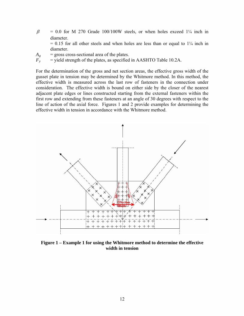
= 0.0 for M 270 Grade 100/100W steels, or when holes exceed 1¼ inch in diameter. = 0.15 for all other steels and when holes are less than or equal to 1¼ inch in diameter.
Ag = gross cross-sectional area of the plates. Fy = yield strength of the plates, as specified in AASHTO Table 10.2A. For the determination of the gross and net section areas, the effective gross width of the gusset plate in tension may be determined by the Whitmore method. In this method, the effective width is measured across the last row of fasteners in the connection under consideration. The effective width is bound on either side by the closer of the nearest adjacent plate edges or lines constructed starting from the external fasteners within the first row and extending from these fasteners at an angle of 30 degrees with respect to the line of action of the axial force. Figures 1 and 2 provide examples for determining the effective width in tension in accordance with the Whitmore method.
Figure 1 – Example 1 for using the Whitmore method to determine the effective width in tension
12
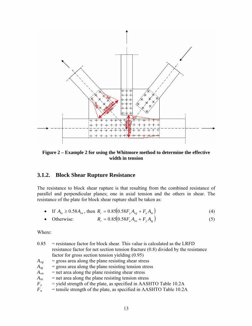
Figure 2 – Example 2 for using the Whitmore method to determine the effective width in tension
3.1.2. Block Shear Rupture Resistance The resistance to block shear rupture is that resulting from the combined resistance of parallel and perpendicular planes; one in axial tension and the others in shear. The resistance of the plate for block shear rupture shall be taken as:
If vn , then tn AA 58.0 tnuvgyr AFAFR 58.085.0 (4)
Otherwise: tgyvnur AFAFR 58.085.0 (5)
Where: 0.85 = resistance factor for block shear. This value is calculated as the LRFD
resistance factor for net section tension fracture (0.8) divided by the resistance factor for gross section tension yielding (0.95)
Avg = gross area along the plane resisting shear stress Atg = gross area along the plane resisting tension stress Avn = net area along the plane resisting shear stress Atn = net area along the plane resisting tension stress Fy = yield strength of the plate, as specified in AASHTO Table 10.2A Fu = tensile strength of the plate, as specified in AASHTO Table 10.2A
13
The analysis of block shear rupture involves the evaluation of several patterns of planes to arrive at the governing pattern. Figure 3 provides some examples of potential block shear rupture planes for gusset plates in tension.
Figure 3 – Examples of potential block shear rupture planes for gusset plates in tension
3.2. Gusset Plates Subject to Shear The shear resistance, Rr, for gusset plates subject to shear shall be taken as the lesser of the shear yield and the shear fracture resistance specified in Equations 6 and 7, respectively:
gyr AFR 58.0 (6)
nur AFR 58.085.0 (7)
where: 0.85 = resistance factor for shear fracture on the net section. This value is calculated as
the LRFD resistance factor for net section tension fracture (0.8) divided by the resistance factor for gross section tension yielding (0.95)
Ag = gross area of the plates resisting shear An = net area of the plates resisting shear Fy = minimum yield strength of the plates Fu = minimum tensile strength of the plates Ω = reduction factor taken as:
14
• Ω = 1.00 when the gusset plates are of ample stiffness to prevent buckling and develop the plastic shear force of the plates, or
• Ω = 0.74 in the absence of a more rigorous analysis or criterion to assure and quantify the stiffness requirements to develop the plastic shear force of the plates.
The analysis of gusset plates for shear involves the evaluation of several shear sections to arrive at the governing section. Figures 4 and 5 provide examples of shear sections to be evaluated in gusset plates in gross section shear yielding and net section shear fracture.
Figure 4 – Examples of gross section shear yielding planes
15
3.3. Gusset Plates in Compression
The proximity of connected members, complex state of stress, and boundary conditions can influence the resistance of gusset plates in compression. Therefore, special care must be exercised to properly assess the buckled shape and compressive resistance of gusset plates in compression. In the absence of a more rigorous analysis, the resistance of gusset plates in compression may be determined as that of idealized members in compression, in accordance with the provisions of AASHTO Article 10.54.1.1. The effective width of the idealized compression member may be determined in accordance with the Whitmore method. The unbraced length, Lc, may be determined as the average of three distances (L1, L2, L3) as follows: where: L2 = The distance from the last row of fasteners in the compression member under
consideration to the first row of fasteners in the closest adjacent member, measured along the line of action of the compressive axial force.
L1, L3 = The distance from each of the ends of the Whitmore width to the first row of
fasteners in the closest adjacent member, measured parallel to the line of action of the compressive axial force. When the Whitmore width enters into the adjacent member, the associated distance at that end should be set to zero.
Figure 6 provides an example showing L1, L2, L3, and effective width for a gusset plate in compression. When lateral sway of gusset plates is possible, the effective length factor, K, for gusset plates may be taken from Table 2 for Cases (d), (e), or (f), depending on the anticipated buckled shape. When lateral sway of gusset plates is not possible, the effective length factor, K, for gusset plates may be taken from Table 2 for Cases (a), (b), or (c), as appropriate.
Table 2 – K Values
Buckled shape
(a)
(b)
(c)
(d) (e) (f)
Theoretical K value 0.5 0.7 1.0 1.0 2.0 2.0 Design K value 0.65 0.80 1.0 1.2 2.1 2.0
16
Whitm
ore W
idth
L 2
L 3 L 1
Whitm
ore W
idth
L 2
L 3 L 1
17
L 2
Whitmore Width
L 3
L 1L 2
Whitmore Width
L 3
L 1
Figure 6 – Examples showing L1, L2, L3, and effective width for a gusset plate in compression.
3.4. Gusset Plates Under Combined Flexural and Axial Loads Gusset plates behave as deep members. Therefore, the application of flexural theory to the analysis of gusset plates is questionable and not required in this Guidance.
3.5. Limiting Slenderness Ratio The existing requirement of length-to-thickness ratio (for the design of unsupported
edges of gusset plates) not to exceed yF/000,11 is equivalent to the slenderness ratio
requirement of 200r
lfor Grade 36 tension members not subject to stress reversal.
Although an appropriate slenderness limit is advisable for the design of new gusset plates, it is not required in this guidance for load rating purposes. However, Owners are advised to evaluate the cause and effect of any excessive out of flatness at the free edges of gusset plates.
II - Load Rating Examples
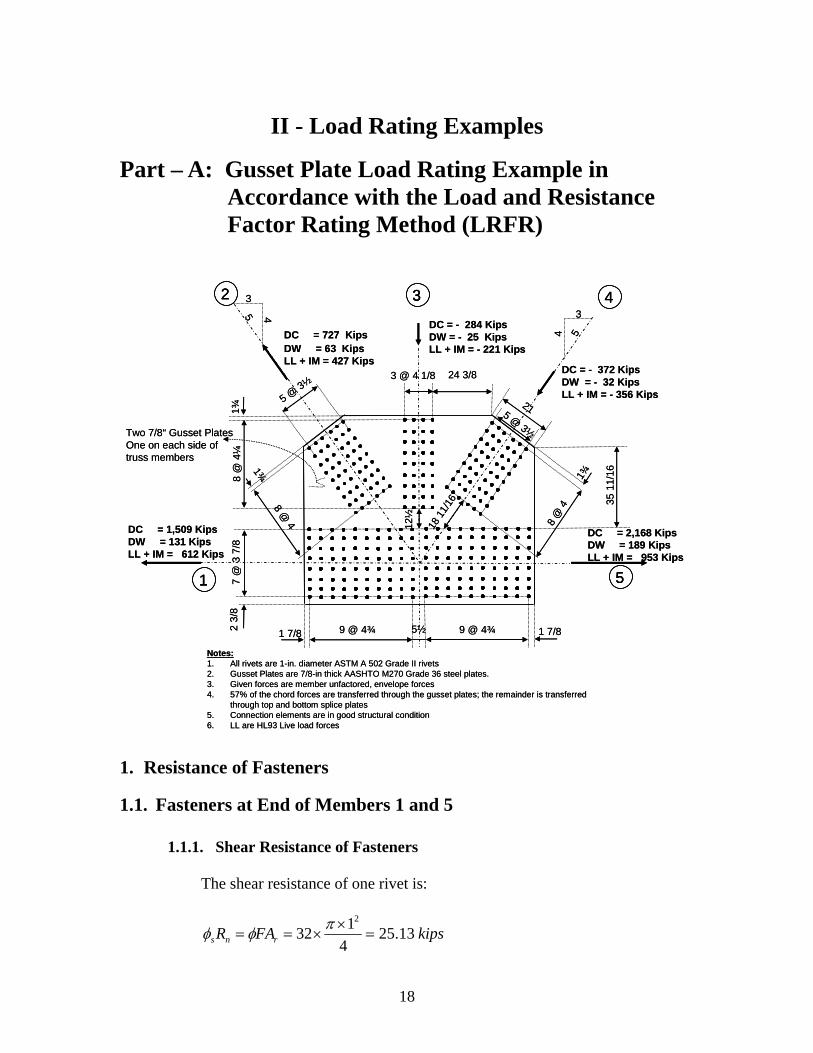
Part – A: Gusset Plate Load Rating Example in Accordance with the Load and Resistance Factor Rating Method (LRFR)
5 @ 3½
7 @
3 7
/82
3/8
3 @ 4 1/8
8 @ 4
1¾
9 @ 4¾ 9 @ 4¾1 7/8 5½
DC = 2,168 KipsDW = 189 KipsLL + IM = 953 Kips
3
4 5
3
45
DC = 1,509 KipsDW = 131 KipsLL + IM = 612 Kips
DC = - 372 KipsDW = - 32 KipsLL + IM = - 356 Kips
DC = - 284 KipsDW = - 25 KipsLL + IM = - 221 Kips
DC = 727 KipsDW = 63 KipsLL + IM = 427 Kips
8 @
4¼
1¾
1 7/8
8 @
4
1¾
5 @ 3½
2112
½
18 1
1/16
Two 7/8“ Gusset PlatesOne on each side of truss members
24 3/8
35 1
1/16
Notes:1. All rivets are 1-in. diameter ASTM A 502 Grade II rivets2. Gusset Plates are 7/8-in thick AASHTO M270 Grade 36 steel plates.3. Given forces are member unfactored, envelope forces4. 57% of the chord forces are transferred through the gusset plates; the remainder is transferred
through top and bottom splice plates5. Connection elements are in good structural condition6. LL are HL93 Live load forces
1
2 43
5
5 @ 3½
7 @
3 7
/82
3/8
3 @ 4 1/8
8 @ 4
1¾
9 @ 4¾ 9 @ 4¾1 7/8 5½
DC = 2,168 KipsDW = 189 KipsLL + IM = 953 Kips
3
4 5
3
45
DC = 1,509 KipsDW = 131 KipsLL + IM = 612 Kips
DC = - 372 KipsDW = - 32 KipsLL + IM = - 356 Kips
DC = - 284 KipsDW = - 25 KipsLL + IM = - 221 Kips
DC = 727 KipsDW = 63 KipsLL + IM = 427 Kips
8 @
4¼
1¾
1 7/8
8 @
4
1¾
5 @ 3½
2112
½
18 1
1/16
Two 7/8“ Gusset PlatesOne on each side of truss members
24 3/8
35 1
1/16
Notes:1. All rivets are 1-in. diameter ASTM A 502 Grade II rivets2. Gusset Plates are 7/8-in thick AASHTO M270 Grade 36 steel plates.3. Given forces are member unfactored, envelope forces4. 57% of the chord forces are transferred through the gusset plates; the remainder is transferred
through top and bottom splice plates5. Connection elements are in good structural condition6. LL are HL93 Live load forces
11
22 4433
55
1. Resistance of Fasteners
1.1. Fasteners at End of Members 1 and 5
1.1.1. Shear Resistance of Fasteners
The shear resistance of one rivet is:
kipsFAR rns 13.254
132
2
18
1.1.2. Plate Bearing Resistance at Fasteners
Clear distance between holes = 21226875.316
1175.4
d
Clear end distance = 2234375.116
11
2
1875.1
d
Since the clear end distance is less than 2.0d, the bearing resistance of one end rivet is:
ucbbnbb tFLR 2.1
kipsRnbb 47.6558875.034375.12.18.0
Therefore, rivet shear controls the resistance of fasteners.
The resistance of all rivets in the connection is:
kipsPr 011,28013.25
1.2. Fasteners at End of Member 2
1.2.1. Shear Resistance of Fasteners
The shear resistance of one rivet is:
kipsFAR rns 13.254
132
2
1.2.2. Plate Bearing Resistance at Fasteners
Clear distance between holes = 21229375.216
114
d
Clear end distance =
2221875.12
1611
75.1
d
Since the clear end distance is less than 2.0d, the bearing resistance of one end rivet is:
ucbbnbb tFLR 2.1
kipsRnbb 4.5958875.021875.12.18.0
Therefore, rivet shear controls the resistance of fasteners.
19
The resistance of all rivets in the connection is:
kipsPr 357,15413.25
1.3. Fasteners at End of Member 3
1.3.1. Shear Resistance of Fasteners
The shear resistance of one rivet is:
kipsFAR rns 13.254
132
2
1.3.2. Plate Bearing Resistance at Fasteners
Clear distance between holes = 21221875.316
1125.4
d
Since the clear distance is larger than 2.0d, the bearing resistance of one rivet is:
ubbnbb dtFR 4.2
kipsRnbb 44.9758875.014.28.0
Therefore, rivet shear controls the resistance of fasteners. The resistance of all rivets in the connection is:
kipsPr 9053613.25
1.4. Fasteners at End of Member 4
1.4.1. Shear Resistance of Fasteners
The shear resistance of one rivet is:
kipsFAR rns 13.254
132
2
1.4.2. Plate Bearing Resistance at Fasteners
Clear distance between holes = 21229375.216
114
d
20
Since the clear distance is larger than 2.0d, the bearing resistance of one rivet is:
ubbnbb dtFR 4.2
kipsRnbb 44.9758875.014.28.0
Therefore, rivet shear controls the resistance of fasteners. The resistance of all rivets in the connection is:
kipsPr 357,15413.25
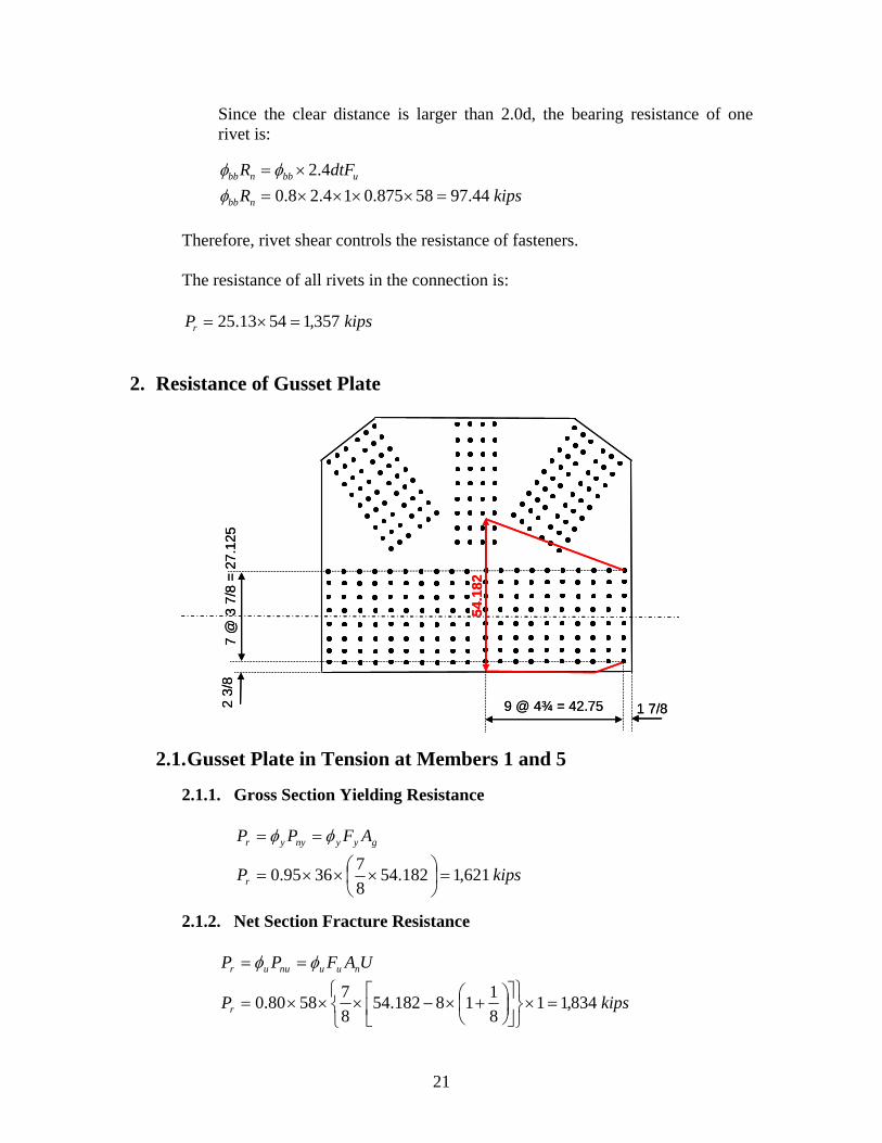
2. Resistance of Gusset Plate
2.1. Gusset Plate in Tension at Members 1 and 5
2.1.1. Gross Section Yielding Resistance
gyynyyr AFPP
kipsPr 621,1182.548
73695.0
2.1.2. Net Section Fracture Resistance
UAFPP nuunuur
kipsPr 834,118
118182.54
8
75880.0
7 @
3 7
/8 =
27
.125
2 3
/8
9 @ 4¾ = 42.75 1 7/8
54.1
82
7 @
3 7
/8 =
27
.125
54.1
82
2 3
/8
9 @ 4¾ = 42.75 1 7/8
21
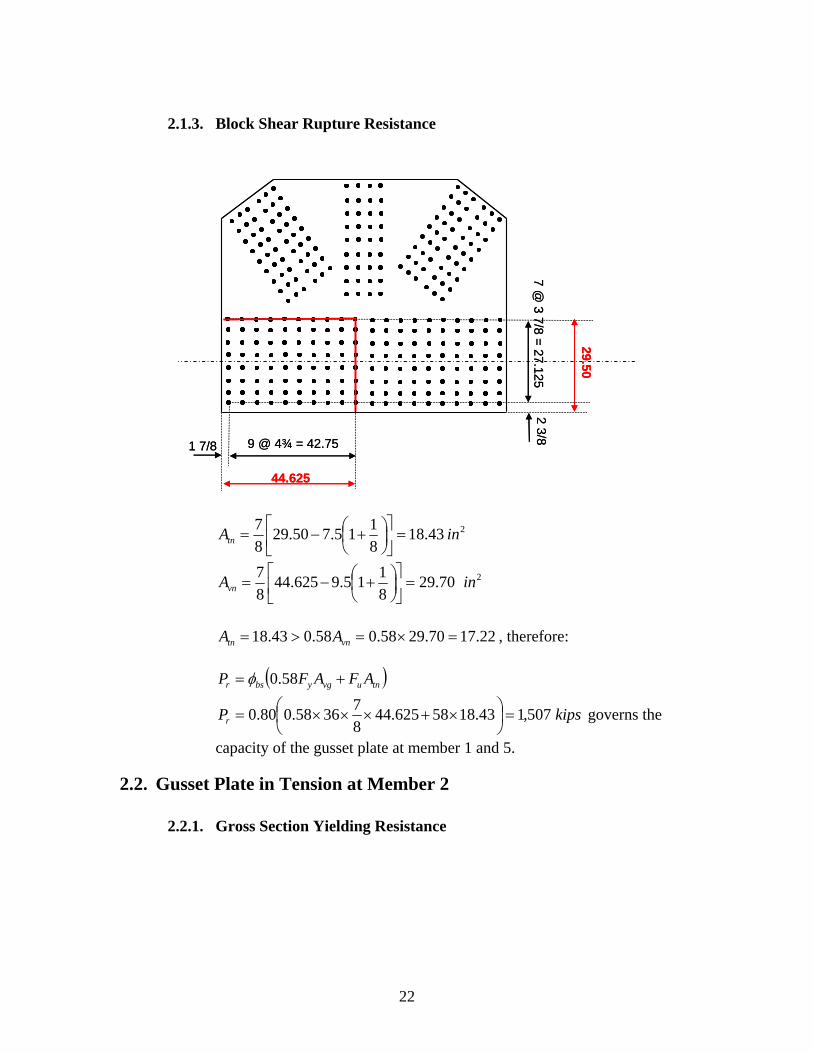
2.1.3. Block Shear Rupture Resistance
7 @ 3 7/8 =
27.1252 3/8
9 @ 4¾ = 42.751 7/8
44.625
29.50
243.188
115.750.29
8
7inAtn
270.298
115.9625.44
8
7inAvn
22.1770.2958.058.043.18 vntn AA , therefore:
tnuvgybsr AFAFP 58.0
kipsPr 507,143.1858625.448
73658.080.0
governs the
capacity of the gusset plate at member 1 and 5.
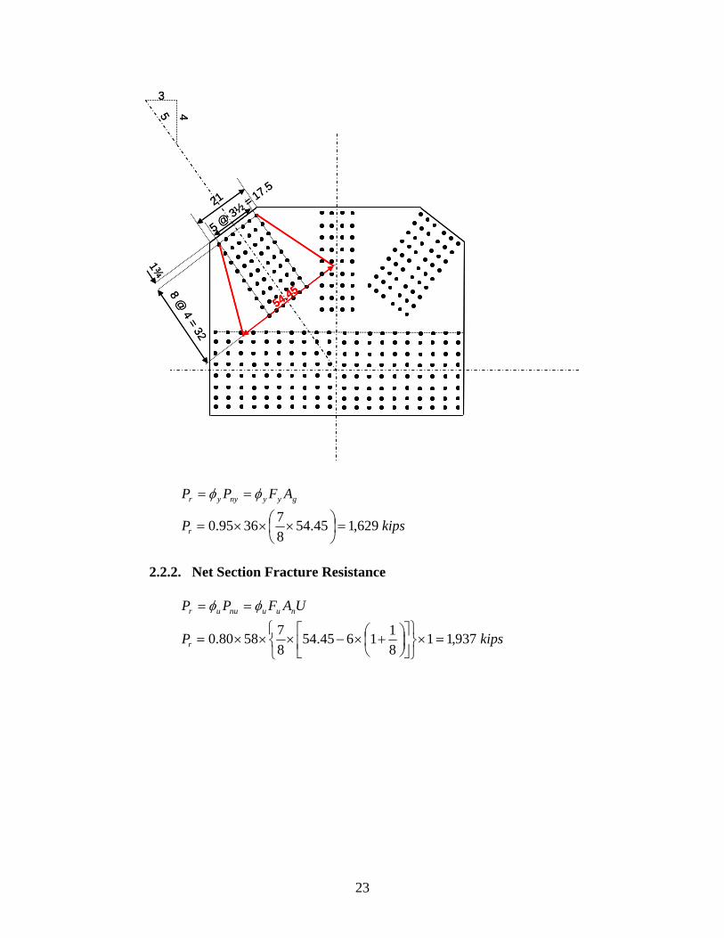
2.2. Gusset Plate in Tension at Member 2
2.2.1. Gross Section Yielding Resistance
7 @ 3 7/8 =
27.1252 3/8
9 @ 4¾ = 42.75
44.625
29.50
1 7/8
22
3
458 @
4 = 32
1¾
5 @ 3½
= 17.521
gyynyyr AFPP
kipsPr 629,145.548
73695.0
2.2.2. Net Section Fracture Resistance
UAFPP nuunuur
kipsPr 937,118
11645.54
8
75880.0
54.45
3
458 @
4 = 32
1¾
5 @ 3½
= 17.521
54.45
23
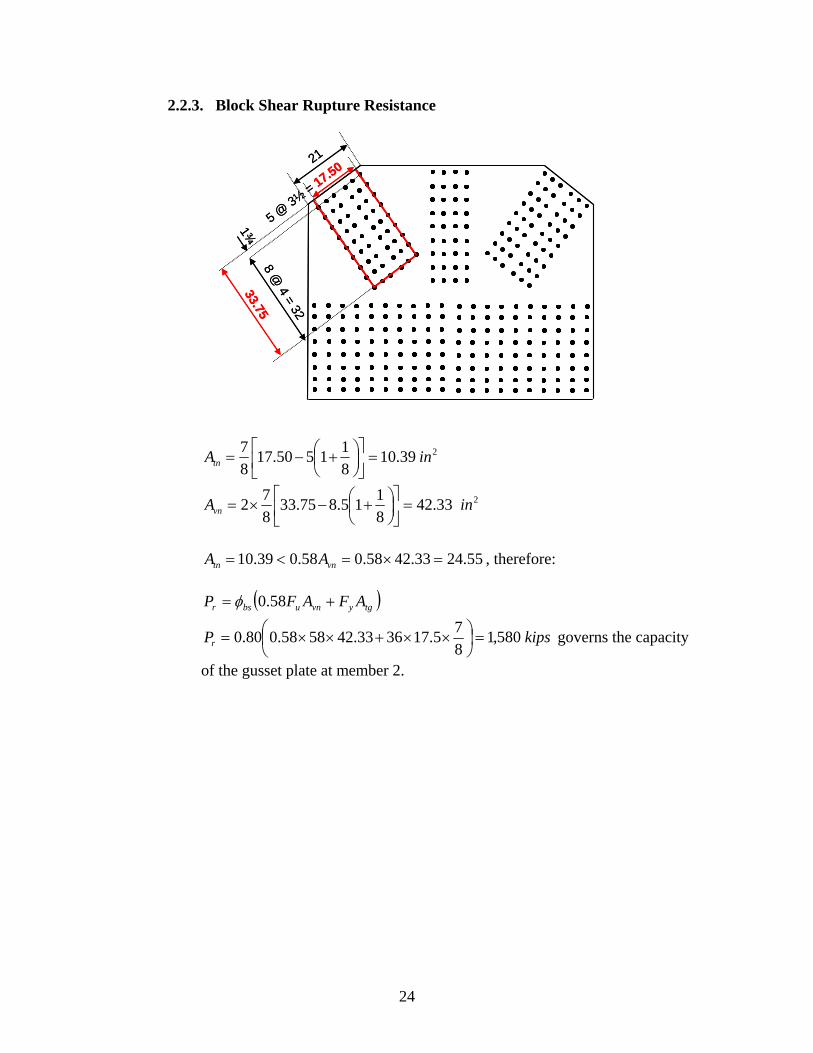
2.2.3. Block Shear Rupture Resistance
8 @ 4 = 32
1¾
5 @ 3½
= 17.5021
239.108
11550.17
8
7inAtn
233.428
115.875.33
8
72 inAvn
55.2433.4258.058.039.10 vntn AA , therefore:
tgyvnubsr AFAFP 58.0
kipsPr 580,18
75.173633.425858.080.0
governs the capacity
of the gusset plate at member 2.
33.758 @
4 = 32
1¾
5 @ 3½
= 17.5021
33.75
24
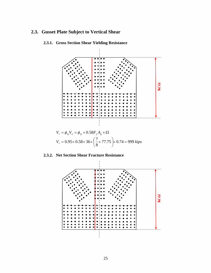
2.3. Gusset Plate Subject to Vertical Shear
2.3.1. Gross Section Shear Yielding Resistance
77.75 77.75
gyvynvyr AFVV 58.0
kipsVr 99974.075.778
73658.095.0
2.3.2. Net Section Shear Fracture Resistance
77.75 77.75
25
nuvunvur AFVV 58.0
kipsVr 592,18
11975.77
8
75858.080.0
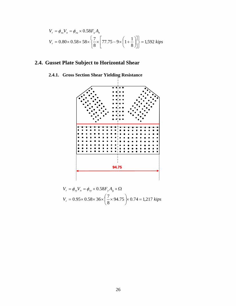
2.4. Gusset Plate Subject to Horizontal Shear
2.4.1. Gross Section Shear Yielding Resistance
94.75 94.75
gyvynvyr AFVV 58.0
kipsVr 217,174.075.948
73658.095.0
26
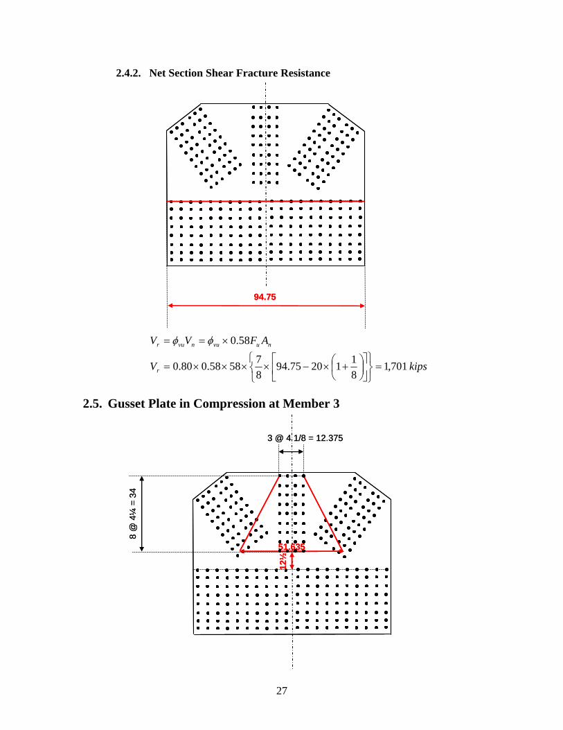
2.4.2. Net Section Shear Fracture Resistance
94.75 94.75
nuvunvur AFVV 58.0
kipsVr 701,18
112075.94
8
75858.080.0
2.5. Gusset Plate in Compression at Member 3
3 @ 4 1/8 = 12.375
12½
51.635
3 @ 4 1/8 = 12.375
12½
51.635
8 @
4¼
= 3
4 8
@ 4
¼=
34
27
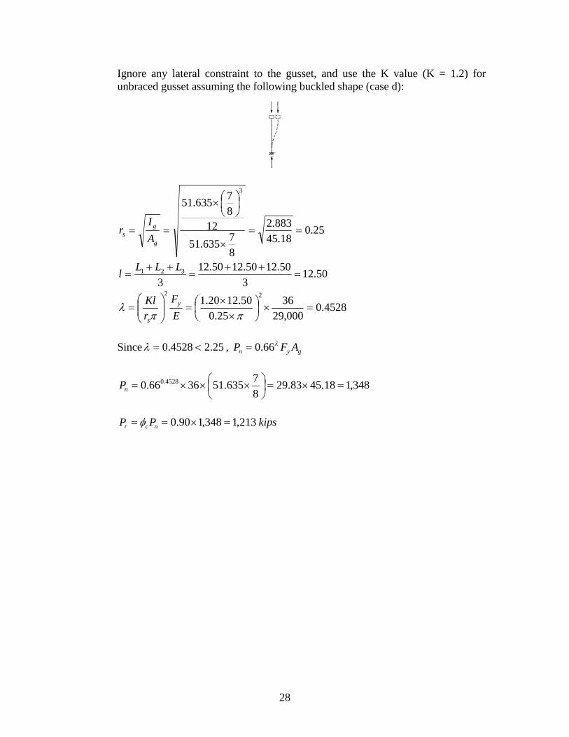
Ignore any lateral constraint to the gusset, and use the K value (K = 1.2) for unbraced gusset assuming the following buckled shape (case d):
25.018.45
883.2
8
7635.51
128
7635.51
3
g
gs A
Ir
50.123
50.1250.1250.12
3321
LLLl
4528.0000,29
36
25.0
50.1220.122
E
F
r
Kl y
s
Since 25.24528.0 , gyn AFP 66.0
348,118.4583.298
7635.513666.0 4528.0
nP
kipsPP ncr 213,1348,190.0
28
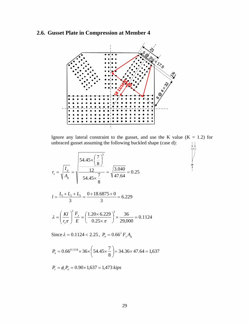
2.6. Gusset Plate in Compression at Member 4
8 @
4
Ignore any lateral constraint to the gusset, and use the K value (K = 1.2) for unbraced gusset assuming the following buckled shape (case d):
25.064.47
040.3
8
745.54
128
745.54
3
g
gs A
Ir
229.63
06875.180
3321
LLLl
1124.0000,29
36
25.0
229.620.122
E
F
r
Kl y
s
Since 25.21124.0 , gyn AFP 66.0
637,164.4736.348
745.543666.0 1124.0
nP
kipsPP ncr 473,1637,190.0
= 32
1¾
5 @ 3½
= 17.5
21
18 1
1/16
54.45
8 @
4 =
32
1¾
5 @ 3½
= 17.5
21
18 1
1/16
54.45
29
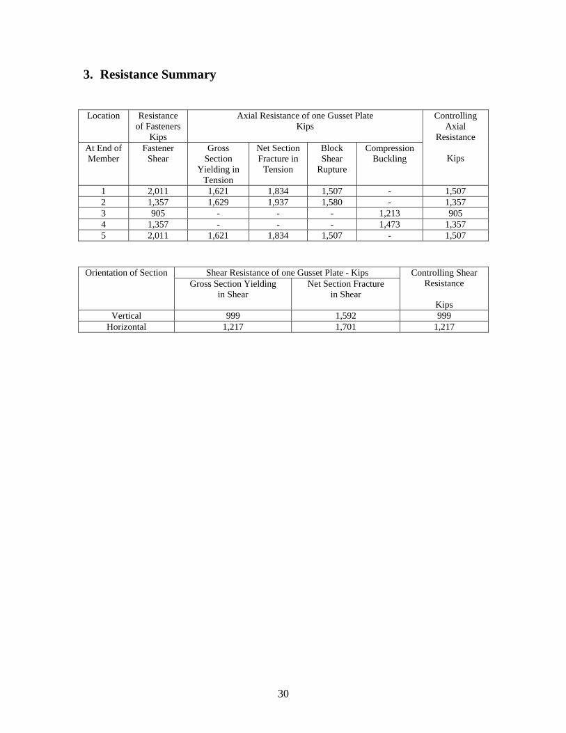
3. Resistance Summary Location Resistance
of Fasteners Kips
Axial Resistance of one Gusset Plate Kips
At End of Member
Fastener Shear
Gross Section
Yielding in Tension
Net Section Fracture in
Tension
Block Shear
Rupture
Compression Buckling
Controlling Axial
Resistance
Kips
1 2,011 1,621 1,834 1,507 - 1,507 2 1,357 1,629 1,937 1,580 - 1,357 3 905 - - - 1,213 905 4 1,357 - - - 1,473 1,357 5 2,011 1,621 1,834 1,507 - 1,507
Shear Resistance of one Gusset Plate - Kips Orientation of Section Gross Section Yielding
in Shear Net Section Fracture
in Shear
Controlling Shear Resistance
Kips
Vertical 999 1,592 999 Horizontal 1,217 1,701 1,217
30
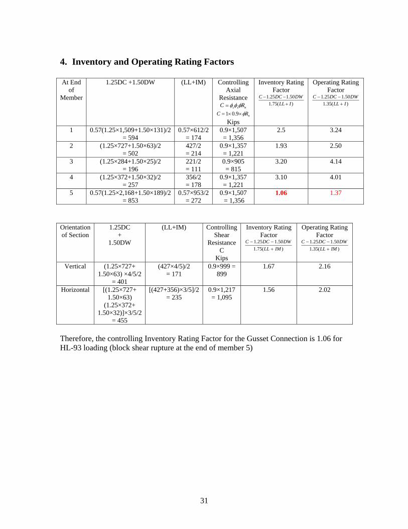
4. Inventory and Operating Rating Factors At End
of Member
1.25DC +1.50DW (LL+IM) Controlling Axial
Resistance nsc RC
nRC 9.01 Kips
Inventory Rating Factor
)(75.1
50.125.1
ILL
DWDCC
Operating Rating Factor
)(35.1
50.125.1
ILL
DWDCC
1 0.57(1.25×1,509+1.50×131)/2 = 594
0.57×612/2 = 174
0.9×1,507 = 1,356
2.5 3.24
2 (1.25×727+1.50×63)/2 = 502
427/2 = 214
0.9×1,357 = 1,221
1.93 2.50
3 (1.25×284+1.50×25)/2 = 196
221/2 = 111
0.9×905 = 815
3.20 4.14
4 (1.25×372+1.50×32)/2 = 257
356/2 = 178
0.9×1,357 = 1,221
3.10 4.01
5 0.57(1.25×2,168+1.50×189)/2 = 853
0.57×953/2 = 272
0.9×1,507 = 1,356
1.06 1.37
Orientation of Section
1.25DC +
1.50DW
(LL+IM) Controlling Shear
Resistance C
Kips
Inventory Rating Factor
)(75.1
50.125.1
IMLL
DWDCC
Operating Rating Factor
)(35.1
50.125.1
IMLL
DWDCC
Vertical (1.25×727+ 1.50×63) ×4/5/2
= 401
(427×4/5)/2 = 171
0.9×999 = 899
1.67 2.16
Horizontal [(1.25×727+ 1.50×63)
(1.25×372+ 1.50×32)]×3/5/2
= 455
[(427+356)×3/5]/2 = 235
0.9×1,217 = 1,095
1.56 2.02
Therefore, the controlling Inventory Rating Factor for the Gusset Connection is 1.06 for HL-93 loading (block shear rupture at the end of member 5)
31
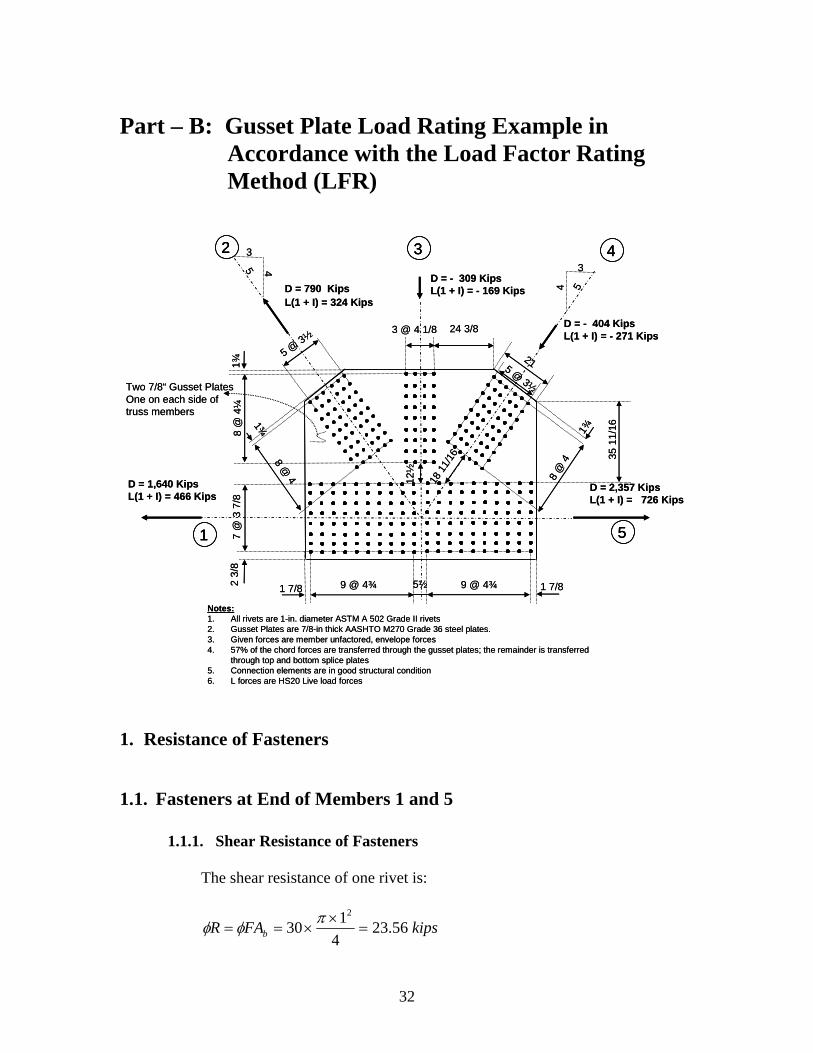
Part – B: Gusset Plate Load Rating Example in Accordance with the Load Factor Rating Method (LFR)
5 @ 3½
7 @
3 7
/82
3/8
3 @ 4 1/8
8 @ 4
1¾
9 @ 4¾ 9 @ 4¾1 7/8 5½
D = 2,357 KipsL(1 + I) = 726 Kips
3
4 5
3
45
D = 1,640 KipsL(1 + I) = 466 Kips
D = - 404 KipsL(1 + I) = - 271 Kips
D = - 309 KipsL(1 + I) = - 169 Kips D = 790 Kips
L(1 + I) = 324 Kips
8 @
4¼
1¾
1 7/8
8 @
4
1¾
5 @ 3½
21
12½
18 1
1/16
Two 7/8“ Gusset PlatesOne on each side of truss members
24 3/8
35 1
1/1
6Notes:1. All rivets are 1-in. diameter ASTM A 502 Grade II rivets2. Gusset Plates are 7/8-in thick AASHTO M270 Grade 36 steel plates.3. Given forces are member unfactored, envelope forces4. 57% of the chord forces are transferred through the gusset plates; the remainder is transferred
through top and bottom splice plates5. Connection elements are in good structural condition6. L forces are HS20 Live load forces
1
2 43
5
5 @ 3½
7 @
3 7
/82
3/8
3 @ 4 1/8
8 @ 4
1¾
9 @ 4¾ 9 @ 4¾1 7/8 5½
D = 2,357 KipsL(1 + I) = 726 Kips
3
4 5
3
45
D = 1,640 KipsL(1 + I) = 466 Kips
D = - 404 KipsL(1 + I) = - 271 Kips
D = - 309 KipsL(1 + I) = - 169 Kips D = 790 Kips
L(1 + I) = 324 Kips
8 @
4¼
1¾
1 7/8
8 @
4
1¾
5 @ 3½
21
12½
18 1
1/16
Two 7/8“ Gusset PlatesOne on each side of truss members
24 3/8
35 1
1/1
6Notes:1. All rivets are 1-in. diameter ASTM A 502 Grade II rivets2. Gusset Plates are 7/8-in thick AASHTO M270 Grade 36 steel plates.3. Given forces are member unfactored, envelope forces4. 57% of the chord forces are transferred through the gusset plates; the remainder is transferred
through top and bottom splice plates5. Connection elements are in good structural condition6. L forces are HS20 Live load forces
11
22 4433
55
1. Resistance of Fasteners
1.1. Fasteners at End of Members 1 and 5
1.1.1. Shear Resistance of Fasteners
The shear resistance of one rivet is:
kipsFAR b 56.234
130
2
32
1.1.2. Plate Bearing Resistance at Fasteners
Clear distance between holes = 6875.316
1175.4
cL
The bearing resistance of an interior rivet is:
uuc dtFtFLR 8.19.0
kipsofR 35.9135.9158875.018.1
16858875.06875.39.0min
Clear end distance = 34375.116
11
2
1875.1
cL
The bearing resistance of an end rivet is:
uuc dtFtFLR 8.19.0
kipsofR 38.6135.9158875.018.1
38.6158875.034375.19.0min
Therefore, rivet shear controls the resistance of fasteners.
The resistance of all rivets in the connection is:
kipsPr 885,18056.23
1.2. Fasteners at End of Member 2
1.2.1. Shear Resistance of Fasteners
The shear resistance of one rivet is:
kipsFAR b 56.234
130
2
1.2.2. Plate Bearing Resistance at Fasteners
Clear distance between holes = 9375.216
114
cL
The bearing resistance of an interior rivet is:
uuc dtFtFLR 8.19.0
kipsofR 35.9135.9158875.018.1
13458875.09375.29.0min
33
Clear end distance =
21875.12
1611
75.1
cL
The bearing resistance of an end rivet is:
uuc dtFtFLR 8.19.0
kipsofR 67.5535.9158875.018.1
67.5558875.021875.19.0min
Therefore, rivet shear controls the resistance of fasteners.
The resistance of all rivets in the connection is:
kipsPr 272,15456.23
1.3. Fasteners at End of Member 3
1.3.1. Shear Resistance of Fasteners
The shear resistance of one rivet is:
kipsFAR b 56.234
130
2
1.3.2. Plate Bearing Resistance at Fasteners
Clear distance between holes = 1875.316
1125.4
cL
The bearing resistance of one rivet is:
uuc dtFtFLR 8.19.0
kipsofR 35.9135.9158875.018.1
59.14558875.01875.39.0min
Therefore, rivet shear controls the resistance of fasteners. The resistance of all rivets in the connection is:
kipsPr 8483656.23
1.4. Fasteners at End of Member 4 1.4.1. Shear Resistance of Fasteners
The shear resistance of one rivet is:
34
kipsFAR b 56.234
130
2
1.4.2. Plate Bearing Resistance at Fasteners
Clear distance between holes = 9375.216
114
cL
The bearing resistance of one rivet is:
uuc dtFtFLR 8.19.0
kipsofR 35.9135.9158875.018.1
17.13458875.09375.29.0min
Therefore, rivet shear controls the resistance of fasteners. The resistance of all rivets in the connection is:
kipsPr 272,15456.23
2. Resistance of Gusset Plate
2.1. Gusset Plate in Tension at Members 1 and 5
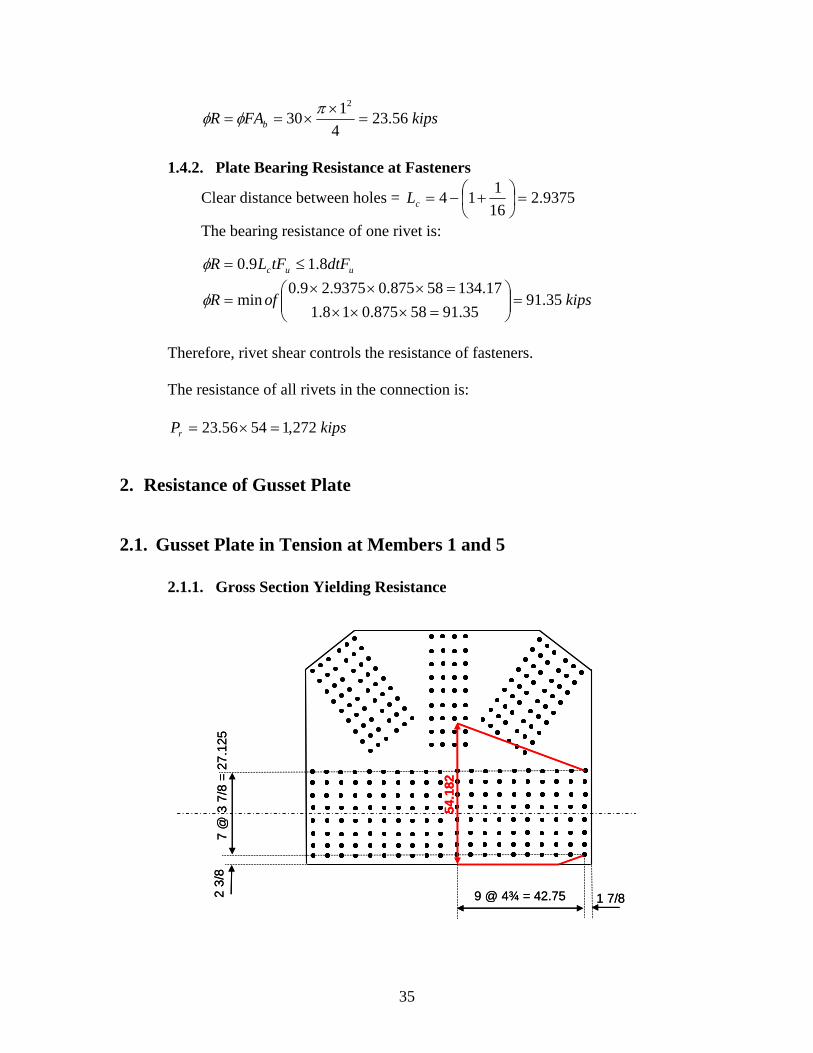
2.1.1. Gross Section Yielding Resistance
7 @
3 7
/8 =
27
.125
2 3
/8
9 @ 4¾ = 42.75 1 7/8
54.1
82
7 @
3 7
/8 =
27
.125
54.1
82
2 3
/8
9 @ 4¾ = 42.75 1 7/8
35
53.398
118182.54
8
7
41.47182.548
7
n
g
A
A
ggne AAAA
64.4641.47
64.4641.4715.053.39min
g
gne A
AAofA
yer FAR
kipsRr 679,13664.46
2.1.2. Block Shear Rupture Resistance
7 @ 3 7/8 =
243.188
115.750.29
8
7inAtn
270.298
115.9625.44
8
7inAvn
22.1770.2958.058.043.18 vntn AA , therefore:
tnuvgyr AFAFR 58.085.0
kipsPr 602,143.1858625.448
73658.085.0
Block shear governs the capacity of the gusset plate at member 1 and 5.
27.1252 3/8
9 @ 4¾ = 42.75
44.625
29.50
1 7/8
7 @ 3 7/8 =
5
27.122 3/8
9 @ 4¾ = 42.75
44.625
29.50
1 7/8
36
2.2. Gusset Plate in Tension at Member 2
2.2.1. Gross Section Yielding Resistance
74.418
11645.54
8
7
64.4745.548
7
n
g
A
A
ggne AAAA
64.4764.47
88.4864.4715.074.41min
g
gne A
AAofA
yer FAR
kipsRr 715,13664.47
3
458 @
4 = 32
1¾
5 @ 3½
= 17.521
54.45
3
458 @
4 = 32
1¾
5 @ 3½
= 17.521
54.45
37
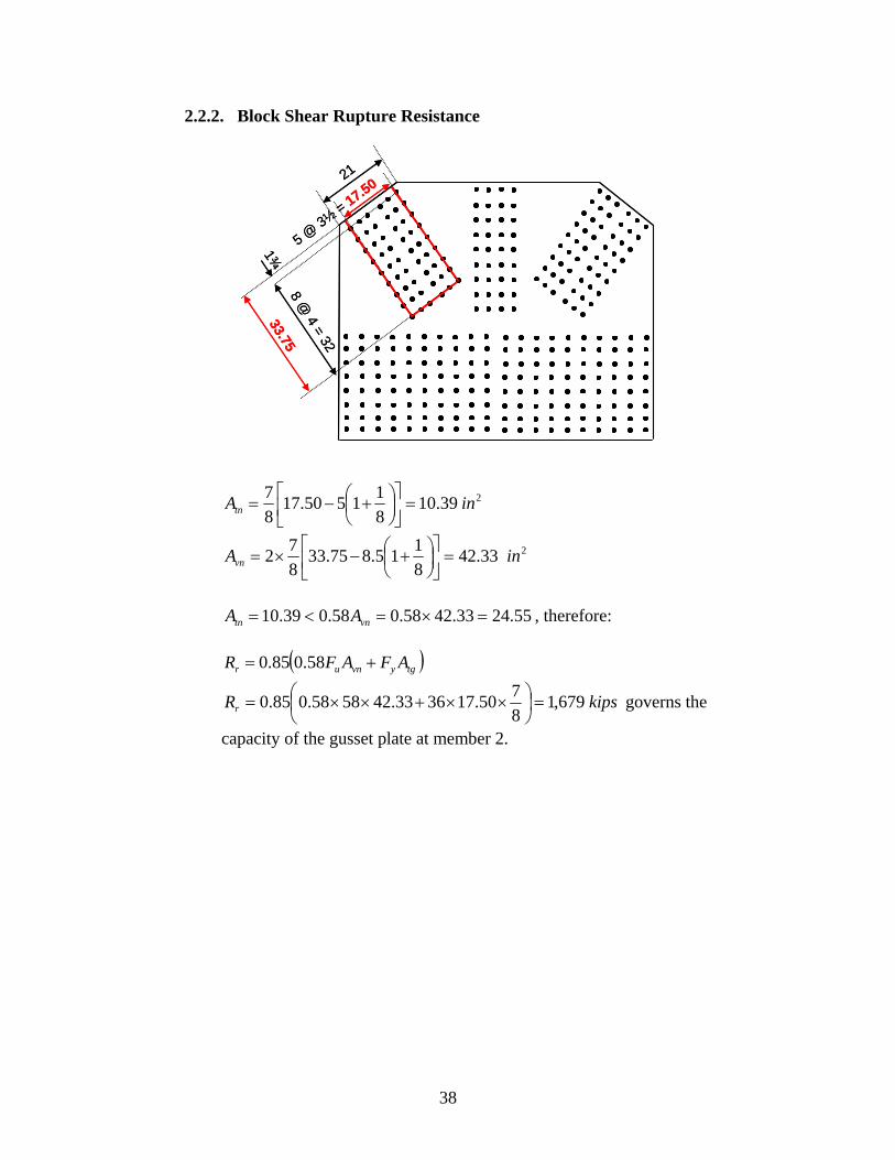
2.2.2. Block Shear Rupture Resistance
8 @ 4 = 32
1¾
5 @ 3½
= 17.5021
239.108
11550.17
8
7inAtn
233.428
115.875.33
8
72 inAvn
55.2433.4258.058.039.10 vntn AA , therefore:
tgyvnur AFAFR 58.085.0
kipsRr 679,18
750.173633.425858.085.0
governs the
capacity of the gusset plate at member 2.
33.758 @
4 = 32
1¾
5 @ 3½
= 17.5021
33.75
38
2.3. Gusset Plate Subject to Vertical Shear
2.3.1. Gross Section Shear Yielding Resistance
77.75 77.75
gyr AFV 58.0
kipsVr 051,174.075.778
73658.0
2.3.2. Net Section Shear Fracture Resistance
77.
75 77.75
39
nur AFV 58.085.0
kipsVr 692,18
11975.77
8
75858.085.0
2.4. Gusset Plate Subject to Horizontal Shear
2.4.1. Gross Section Shear Yielding Resistance
94.75 94.75
gyr AFV 58.0
kipsVr 281,174.075.948
73658.0
40
2.4.2. Net Section Shear Fracture Resistance
nur AFV 58.085.0
kipsVr 808,18
112075.94
8
75858.085.0
94.75 94.75
2.5. Gusset Plate in Compression at Member 3
3 @ 4 1/8 = 12.375
12½
51.635
3 @ 4 1/8 = 12.375
12½
51.635
8 @
4¼
= 3
4 8
@ 4
¼=
34
41
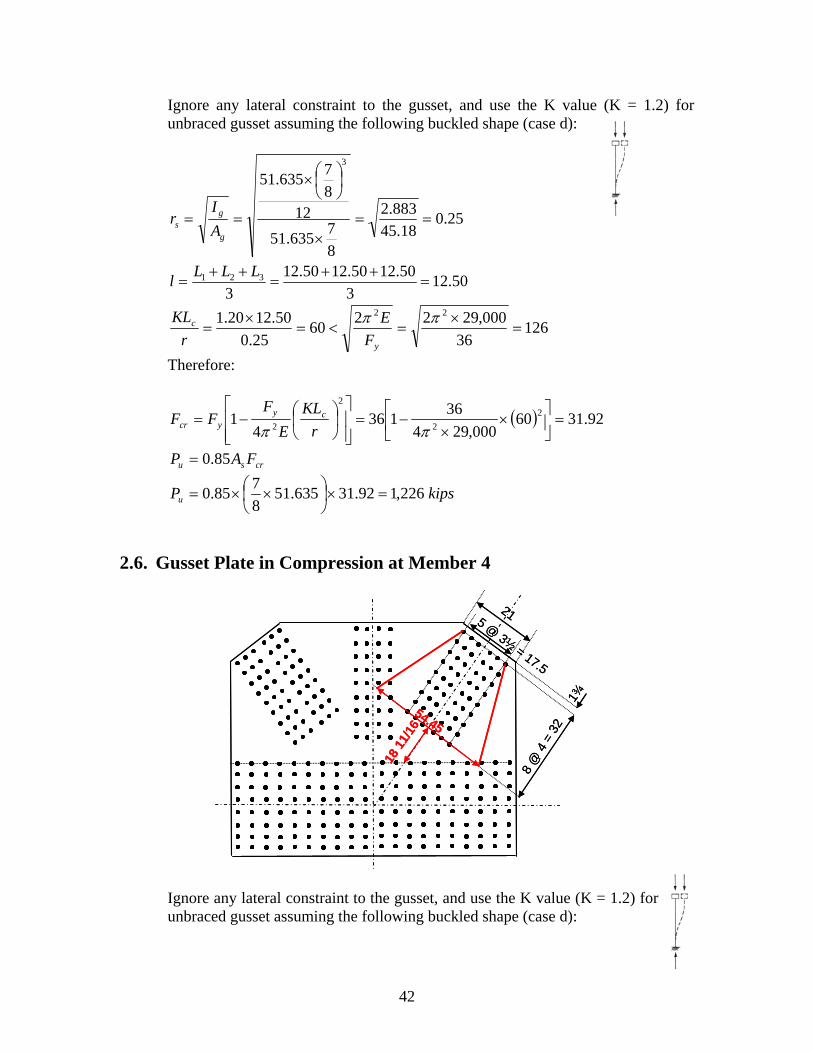
Ignore any lateral constraint to the gusset, and use the K value (K = 1.2) for unbraced gusset assuming the following buckled shape (case d):
25.018.45
883.2
8
7635.51
128
7635.51
3
g
gs A
Ir
50.123
50.1250.1250.12
3321
LLLl
12636
000,292260
25.0
50.1220.1 22
y
c
F
E
r
KL
Therefore:
92.3160000,294
36136
41 2
2
2
2
r
KL
E
FFF cy
ycr
crsu FAP 85.0
kipsPu 226,192.31635.518
785.0
2.6. Gusset Plate in Compression at Member 4
Ignore any lateral constraint to the gusset, and use the K value (K = 1.2) for unbraced gusset assuming the following buckled shape (case d):
8 @
4 =
32
1¾
5 @ 3½
= 17.5
21
18 1
1/16
54.45
8 @
4 =
32
1¾
5 @ 3½
= 17.5
21
18 1
1/16
54.45
42
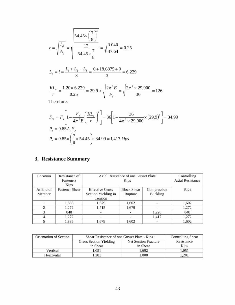
25.064.47
040.3
8
745.54
12
8
745.54
3
g
g
A
Ir
229.63
06875.180
3321
LLLlLc
12636
000,29229.29
25.0
229.620.1 22
y
c
F
E
r
KL
Therefore:
99.349.29000,294
36136
41 2
2
2
2
r
KL
E
FFF cy
ycr
crsu FAP 85.0
kipsPu 417,199.3445.548
785.0
3. Resistance Summary
Location Resistance of Fasteners
Kips
Axial Resistance of one Gusset Plate Kips
At End of Member
Fastener Shear Effective Gross Section Yielding in
Tension
Block Shear Rupture
Compression Buckling
Controlling Axial Resistance
Kips
1 1,885 1,679 1,602 - 1,602 2 1,272 1,715 1,679 - 1,272 3 848 - - 1,226 848 4 1,272 - - 1,417 1,272 5 1,885 1,679 1,602 - 1,602
Shear Resistance of one Gusset Plate - Kips Orientation of Section Gross Section Yielding
in Shear Net Section Fracture
in Shear
Controlling Shear Resistance
Kips Vertical 1,051 1,692 1,051
Horizontal 1,281 1,808 1,281
43
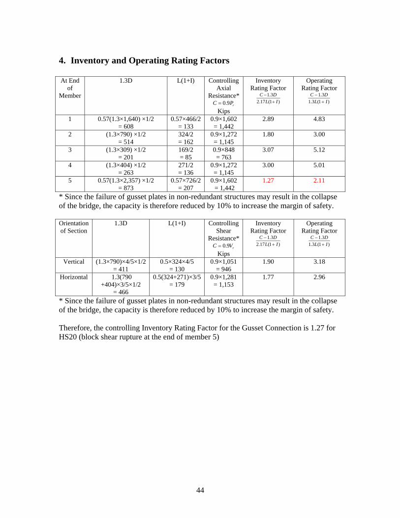
4. Inventory and Operating Rating Factors At End
of Member
1.3D L(1+I) Controlling Axial
Resistance* rPC 9.0
Kips
Inventory Rating Factor
)1(17.2
3.1
IL
DC
Operating Rating Factor
)1(3.1
3.1
IL
DC
1 0.57(1.3×1,640) ×1/2 = 608
0.57×466/2 = 133
0.9×1,602 = 1,442
2.89 4.83
2 (1.3×790) ×1/2 = 514
324/2 = 162
0.9×1,272 = 1,145
1.80 3.00
3 (1.3×309) ×1/2 = 201
169/2 = 85
0.9×848 = 763
3.07 5.12
4 (1.3×404) ×1/2 = 263
271/2 = 136
0.9×1,272 = 1,145
3.00 5.01
5 0.57(1.3×2,357) ×1/2 = 873
0.57×726/2 = 207
0.9×1,602 = 1,442
1.27 2.11
* Since the failure of gusset plates in non-redundant structures may result in the collapse of the bridge, the capacity is therefore reduced by 10% to increase the margin of safety. Orientation of Section
1.3D L(1+I) Controlling Shear
Resistance* rVC 9.0
Kips
Inventory Rating Factor
)1(17.2
3.1
IL
DC
Operating Rating Factor
)1(3.1
3.1
IL
DC
Vertical (1.3×790)×4/5×1/2 = 411
0.5×324×4/5 = 130
0.9×1,051 = 946
1.90 3.18
Horizontal 1.3(790 +404)×3/5×1/2
= 466
0.5(324+271)×3/5 = 179
0.9×1,281 = 1,153
1.77 2.96
* Since the failure of gusset plates in non-redundant structures may result in the collapse of the bridge, the capacity is therefore reduced by 10% to increase the margin of safety. Therefore, the controlling Inventory Rating Factor for the Gusset Connection is 1.27 for HS20 (block shear rupture at the end of member 5)
44


![NATURAL SCIENCES D568/12 ADMISSIONS ASSESSMENT 40 … · Ω, 2 Ω, 4 Ω, 8 Ω, 16 Ω, 32 Ω, 64 Ω, … connected in parallel with the cell. ... [2 marks] Answer: ... is used as the](https://img.pdfslide.us/doc/110x75/5f2363f7b03d7e4ce06bc15b/natural-sciences-d56812-admissions-assessment-40-2-4-8-16-32.jpg)