Embed Size (px)
Citation preview

ORIGINAL PAPER
Crystal Structures and Hirshfeld Surface Analysesof 6-Substituted Chromones
Sahan R. Salpage1 • Mark D. Smith1 • Linda S. Shimizu1
Received: 9 December 2015 / Accepted: 25 February 2016 / Published online: 5 March 2016
� Springer Science+Business Media New York 2016
Abstract Here,we compare structures determinedbyX-ray
diffraction and subsequent Hirshfeld surface analysis to
identify and understand the non-covalent interactions within
the lattices of chromone, 6-methylchromone, 6-methoxy-
chromone, 6-fluorochromone, and 6-chlorochromone with
reported6-bromochromone. In chromone,H-bonds andCH–kinteractions predominate. H-bonds and aryl-stacking inter-
actions are distinct in 6-methylchromone and 6-methoxy-
chromone. The 6-fluorochromone, showed two types of
H-bonds with O���H bonds having a greater contribution than
F���H. In contrast, 6-chlorochromone and 6-bromochromone,
the halogen contributes the larger percentage of stabilizing
H-bonding with Cl���H and Br���H predominating over the
O���Hbonds.Compound1 crystallizes in themonoclinic space
group P21/n with a = 8.1546(8) A, b = 7.8364(7) A,
c = 11.1424(11) A,b = 108.506(2)� andZ = 4.Compound
2 crystallizes in the triclinic space group P-1 with
a = 7.0461(3) A, b = 10.2108(5) A, c = 10.7083(5) A,
a = 89.884(2)�,b = 77.679(2)�, c = 87.367(2)� andZ = 4.
Compound 3 crystallizes in the monoclinic space group P21/
n with a = 8.1923(4) A, b = 7.0431(3) A, c =
15.3943(8) A, b = 92.819(2)� and Z = 4. Compound 4
crystallizes in the triclinic space group P1 with
a = 3.7059(2) A, b = 6.1265(4) A, c = 7.6161(5) A,
a = 84.085(3)�,b = 87.070(3)�, c = 83.390(3)� andZ = 1.
Compound 5 crystallizes in the monoclinic space group P21with a = 3.8220(2) A, b = 5.6985(2) A, c = 16.9107(7) A,
b = 95.8256(18)� and Z = 2.
Graphical Abstract The effect of substituents at the
6-position on chromone on their crystal structures using
Hirshfeld surface and fingerprint analysis.
Keywords Chromones � Single crystals � Non-covalentinteractions � Hirshfeld surface analysis � Fingerprint plots
Introduction
Crystal engineering is a widely used tool that seeks to
understand and control non-covalent intermolecular inter-
actions to organize molecules on the molecular level with
the goal of producing functional solid-state materials [1–7].
Elucidating the principles of crystal engineering could
allow one to readily and reproducibly afford solids with
predictable properties and reactivity that can be used in
molecular recognition [8, 9], molecular and supramolecular
devices [10, 11], storage [12, 13], and catalysis [14, 15].
However, understanding the intricate molecular recogni-
tion process that takes place during crystallization to form
highly ordered crystalline structures remains a challenge
[16, 17]. The information gathered from single crystal
X-ray studies and subsequent analysis of the molecular
surfaces by modelling techniques provides insight into this
& Linda S. Shimizu
1 Department of Chemistry and Biochemistry, University of
South Carolina, Columbia, SC 29208, USA
123
J Chem Crystallogr (2016) 46:170–180
DOI 10.1007/s10870-016-0642-2

complex process. This paper investigates the substituent
effect on molecular packing of 6-substituted chromones by
employing a combination of single crystal X-ray diffrac-
tion (SCXRD) and Hirshfeld analysis. Herein, the 6-posi-
tion of chromone is substituted with a series of electron
donating or electron withdrawing substituents, which
allows alteration of the electronic properties of the aryl ring
as well as introduces additional intermolecular forces
innate to the specific substituent. We analyzed the solid
state structures of these compounds by SCXRD and
observed different packing pattern of molecules in each
crystal lattice. Hirshfeld based surface tools were then used
to identify and quantify the subtle change in the non-co-
valent interactions that contribute to the different assembly
motifs.
Chromones are oxygen-containing heterocyclic com-
pounds that have a benzoannelated c-pyrone moiety as the
core structure. The chromone scaffold can be found in
plants as flavonoids and is employed in medicinal chem-
istry [18–20]. Studies by Ishar et al. showed that 6-chloro-
and 6-fluorochromone-containing structures have promis-
ing anti-cancer activity both in vitro and in vivo [21].
Chromones undergo UV light induced reactions including
[2 ? 2] photodimerizations [22, 23] as well as reactions
with olefins and acetylenes [24, 25]. Despite their signifi-
cance, few structures of simple chromone derivatives have
been reported in the Cambridge Structural Database (CSD).
Our interest in chromones stems from the use nanochannels
of self-assembled bis-urea macrocycles to modulate their
photoreactivity in the solid-state [26]. In 1964, Schmidt set
forth topochemical postulates, which correlated solid state
structure and photochemical reactivity [27–29]. Specifi-
cally, non-covalent intermolecular interactions contribute
to the molecular orientation of the crystal lattice and play
important roles in determining the nature of the excited
states of a molecule, exerting control over photochemical
transformations in the solid-state and influence the struc-
ture of the final photoproducts. Therefore, we were inter-
ested in the structure and reactivity of these compounds in
the absence of the host. Here, we investigate simple
chromones to analyze (a) the crystal structures and
molecular packing of these chromones, and (b) the inter-
actions that govern lattice stability of a series of 6-substi-
tuted chromones to identify the major effects of the
substituent on the assembled structure.
To compare and contrast the molecular arrangements
within these structures, we turned to molecular surface
mapping techniques. Models of molecular surfaces such
as common fused sphere van der Waals and smoothed
Connolly surfaces are defined only by the molecule itself.
In contrast, the Hirshfeld method generates the molecular
surface by combining single molecule information with
the proximity of its nearest neighbors [30–34]. This
model relies on the use of high resolution crystal structure
data that includes positions of the hydrogen atoms and
solvents. Disordered crystal structures typically yield poor
and unrealistic surfaces [35]. Hirshfeld surfaces elucidate
close contacts between molecules and offer a compre-
hensive picture by providing the distribution of the
intermolecular contacts between the molecules in the
lattice using 2D fingerprint maps. Further, they help
identify and provide basic quantitative analysis of the
major interactions that are responsible for packing in
crystals.
This paper systematically investigates the molecular
packing behavior of chromone and a series of simple
chromone derivatives which differ in their electronic
characteristics. We have selected chromone (1) and five
6-substituted derivatives. Compounds 6-methylchromone
(2), and 6-methoxychromone (3) contain electron donating
methyl and methoxy groups at the 6 position respectively.
In comparison, 6-fluorochromone (4), 6-chlorochromone
(5), and 6-bromochromone (6) have electron withdrawing
halogens F, Cl, and Br as the substituents. We have
obtained single crystals of compounds 1-5 and determined
their structures by SCXRD. X-ray data for compound 6
was reported previously [36]. Analysis showed four dif-
ferent molecular arrangements in the solid state within
these six derivatives. The Hirshfeld surface analysis sug-
gest that O���H hydrogen bonding, CH–k, and aryl-stacking
interactions play major roles in stabilizing the lattice
structures containing electron donating substitutes, while
derivatives containing electron withdrawing substituents
display O���H and X���H (X = F, Cl, or Br) hydrogen
bonding as the major packing interactions.
Experimental
Materials and Methods
Compounds 1 and 4 were purchased from Sigma-Aldrich
and compounds 2, 3, and 5 were purchased from Indofine
Chemical Company. All compounds and solvents were
used without further purification. The crystal structure of
the compound 6 was previously reported by Staples et al.
[36].
Crystallization of (C9H6O2) (1), (C10H8O2) (2),
and (C10H8O3) (H2O) (3)
Each derivative (50 mg) was dissolved in 0.1 mL chloro-
form in a scintillation vial. Hexanes were then added
dropwise to obtain colorless crystals.
J Chem Crystallogr (2016) 46:170–180 171
123

Crystallization of C9H5FO2 (4), and C9H5ClO2 (5)
Each derivative (50 mg) was heated with 2 mL of ace-
tonitrile in a scintillation vial to obtain a clear solution. The
solutions were cooled down to room temperature to obtain
colorless crystals.
Single-Crystal Structure Determination
Single crystal X-ray data for all compounds were collected
at 100(2) K using Mo Ka radiation (k = 0.71073 A). Data
for 1 were measured using a Bruker SMART APEX I
diffractometer [37]. Data for compounds 2, 3, 4, and 5 were
collected using a Bruker D8 QUEST diffractometer
equipped with a PHOTON 100 CMOS area detector and an
Incoatec microfocus source [37]. The raw area detector
data frames were reduced and corrected for absorption
effects using the SAINT? and SADABS programs [37].
Structures were solved by direct methods with SHELXS or
SHELXT [38]. Subsequent difference Fourier calculations
and full-matrix least-squares refinement against F2 were
performed with SHELXL-2014 [38] using OLEX2 [39].
All non-hydrogen atoms were refined with anisotropic
displacement parameters. Hydrogen atoms were located in
Fourier difference maps and either refined freely (1 and 4)
or as standard riding atoms with refined isotropic dis-
placement parameters (2, 3, 5). Crystal data for the com-
pounds 1–6 are presented in the Table 1.
Generation of the Hirshfeld Surfaces
Molecular Hirshfeld surfaces for compounds 1–6 were
constructed using Crystal Explorer 3.1 [40]. The Crystal-
lographic Information File (.cif) of each structure was
imported into Crystal Explorer and a high resolution Hir-
shfeld surface was mapped with the functions (a) dnorm and
(b) curvedness.
Results and Discussion
Six chromones were crystallized that differ only in the
substituent at the 6-position. This substituent served to
modulate the electronics of the fused benzene ring by
changing hydrogen at C-6 (1) to either electron donating
groups including methyl (2) or methoxy (3) or electron
withdrawing groups including as fluoro (4), chloro (5), or
bromo (6). We explored how the change of electronics of
the ring affects the molecular packing in the crystalline
state by analyzing single crystal X-ray diffraction data.
Each molecular surface was then mapped by Hirshfeld
analysis to (a) analyze the number and types of non-co-
valent interactions that are present and (b) evaluate percent
contribution of each interaction on lattice structure stabi-
lization. The electronic effects of changing the substituent
at the 6-position on the ring were also compared with the
beta value of the substituent, or its ability to act as a
hydrogen bond acceptor.
Description of the Crystal Structures
Chromone, 6-methylchromone, and 6-methoxychromone
were crystallized from a mixture of CHCl3/hexane. Chro-
mone crystalized in the monoclinic space group P21/n as
solvent-free, colorless plates. 6-methylchromone crystal-
lized in the space group P-1 (No. 2) of the triclinic system
as solvent-free blocky colorless crystals. Hydrated color-
less flat needle crystals of 6-methoxychromone crystallized
in the monoclinic space group P21/n. Solvent-free crystals
of compounds 6-fluorochromone and 6-chlorochromone
were obtained from acetonitrile solutions. Colorless nee-
dle-like crystals of 6-fluorochromone crystallized in the
triclinic system in the acentric space group P1 (No. 1) and
6-chlorochromone crystalized as colorless plates in the
acentric monoclinic space group P21.
In simple aromatic scaffolds such as chromone, typical
organization occurs through aryl stacking of electron rich
part of a one molecule over an electron poor part of another
molecule to minimize the overall dipole in the crystal lat-
tice. As expected, we observed the aryl stacking of
neighboring molecules in chromone 1 in an orientation that
minimizes the overall dipoles (Fig. 1). Individual mole-
cules associate in a pairwise fashion, with neighboring
pairs arranged edge-to-face. The off-set aryl stacking
interactions have a centroid-to-centroid distance of
3.614(1) A, which was calculated using 10 ring atoms
between two adjacent molecules. Although the polar
ketone oxygen is a good hydrogen bond acceptor (b = 5.8,
estimate for simple ketone), apart from the hydrate struc-
ture of 3 these molecules contain only weak hydrogen bond
donors of the type aryl-H (a * 1.0) or aryl-CH3. Addi-
tional stabilization is contributed by edge-to-face CH-pi
interactions with a normalized H-centroid distance of
2.899(2) A distance of 2.9 A as shown in the Fig. 2a.
A simple substitution of a methyl group for the H at the
6-position gives compound 2. The lone pairs of ketone
oxygen of one molecule forms two hydrogen bonds with
methyl (C–H) groups of two adjacent molecules with
C=O1A–C10B distances of 3.504(2) and 3.541(2) A. A
hydrogen bond is also present between the ketone oxygen
of one methyl chromone molecule and the H atom next to
ring oxygen of a neighboring molecule with C=O1A–C3B
distance of 3.226(2) A. Here, methyl is a mild electron
donating group (2.3 Pauling scale) [41] compared to
hydrogen (2.28) in chromone. In contrast to the pairwise
groupings in 1, we observed stacked columns of molecules
172 J Chem Crystallogr (2016) 46:170–180
123

of 2 extending along the crystallographic a axis, as illus-
trated in Fig. 1b. Individual molecules within each stack
are oriented to minimize the overall dipole, with adjacent
molecules related by an inversion center. The offset aryl
stacking interactions show an average centroid to centroid
distance of 3.590(2) A which is calculated between two
adjacent molecules considering 10 ring atoms of each
molecule. The offset of distance is 1.2 A.
The 6-methoxy chromone 3 crystallized as a monohy-
drate with the water acting primarily as a hydrogen bond-
ing donor with the nearest chromone molecules. Water is
also an acceptor of a CH–O interaction. The two carbonyl
Table 1 Crystal data and refinement results for compounds 1–6
1 2 3 4 5 6d
CCDC deposition numbers 1415399 1415400 1415401 1415402 1415403 293294
Empirical formula C9H6O2 Cl0H8C2 C10H8O3�H2O C9H502F C9H5O2C1 C9H5O2Br
M 146.14 160.16 194.18 164.13 180.58 225.04
Crystal system Monoclinic Triclinic Monoclinic Triclinic Monoclinic Monoclinic
Space group P2/n P-1 P2/n P1 P21 P21
Flack parameter n.a. n.a. n.a. Opposites averaged 0.01(2) Not given
a (A) 8.1546(8) 7.0461(3) 8.1923(4) 3.7059(2) 3.8220(2) 3.922(1)
b (A) 7.8364(7) 10.2108(5) 7.0431(3) 6.1265(4) 5.6985(2) 5.723(2)
c (A) 11.1424(11) 10.7083(5) 15.3943(8) 7.6161(5) 16.9107(7) 17.208(5)
a (�) 90 89.884(2) 90 84.085(3) 90 90
b (�) 108.506(2) 77.679(2) 92.819(2) 87.070(3) 95.8256(18) 95.447(6)
c (�) 90 87.367(2) 90 83.390(3) 90 90
V/A3 675.21(11) 751.86(6) 887.16(7) 170.719(18) 366.41(3) 384.5
Z 4 4 4 1 2 2
Dc/g cm-3 1.438 1.415 1.454 1.596 1.637 1.944
l/mm-1 0.102 0.098 0.113 0.131 0.464 5.29
2hmax (�) 55.460 52.734 56.620 56.562 56.652 55.7
h, k, l ranges -10 to 10,
-10 to 10,
-14 to 14
-8 to 8,
-12 to 12,
-13 to 13
-10 to 10,
-9 to 9,
-20 to 20
-4 to 4,
-8 to 8,
-10 to 10
-5 to 5,
-7 to 7,
-22 to 22
Not given
F(000) 304 336 408 84 184 220
Rl,a wR2b [I[ 2a(I)] 0.0376, 0.1047 0.0380, 0.1066 0.0375, 0.1005 0.0332, 0.0868 0.0251, 0.0617 0.038, 0.106
GOFc on F2 1.042 1.089 1.044 1.060 1.153 Not given
a R1 = R||Fo| - |Fc||/R|Fo|b wR2 = {R[w(Fo
2-Fc2)2]/R[w(Fo
2)2]}1/2
c GOF = S = {R[w(Fo2-Fc
2)2]/(n-p)}1/2, w = 1/[r2(Fo2) ? (aP)2 ? bP] where P is [2Fc
2 ? Max(Fo2,0)]/3
d Reference [36]
Fig. 1 Probes for the effects of electron donating groups at the
6-position. a Stacking pattern of chromone (1) in the crystal lattice
highlights the aryl stacking and CH–k interactions. b Orientation of
6-methylchromone (2) molecules highlights the aryl stacking inter-
actions. c Packing of 6-methoxychromone (3) in the crystal highlightsthe aryl stacking interactions
J Chem Crystallogr (2016) 46:170–180 173
123

oxygen lone pairs of chromone act as acceptors to form two
hydrogen bonds with two water molecules with O–O dis-
tance of 2.847(2) and 2.850(2) A. The OH–O hydrogen
bonding forms spiral chains following the crystallographic
21 screw axis along the monoclinic b direction. Another
water molecule acts as an acceptor to the H atom adjacent
to ring oxygen to form a hydrogen bond with C–O distance
of 3.223(2) A. The methoxy group is a stronger electron
donating group (3.7) versus methyl or hydrogen in 2 or 1
[41]. Neighboring chromones stack into columns along the
crystallographic b direction through aryl stacking distance
of 3.524(2) A (centroid to centroid distance calculated
between two adjacent molecules considering 10 ring atoms
of each molecules) and offset distance of 1.2 A (Fig. 1c).
These columns are similar in relative orientation to the
previous compounds. Adjacent molecules in each stack are
related by crystallographic inversion.
Next, we examine the effects of incorporating halides, as
electron withdrawing groups at the 6-position. Halogens F,
Cl, and Br are known to form variety of non-covalent
interactions including hydrogen bonds, halogen bonds, and
C-X–k interactions. We observed a markedly different
Fig. 2 Crystal structure of chromones containing electron withdraw-
ing groups at the 6-position. a Columnar stacks of 6-fluorochromone
arrange along the crystallographic a axis b Columnar stacks of
6-chlorochromone arrange in herring bone type structure. c Columnar
stacks of 6-bromochromone arrange in herring bone type structure.
(Offset aryl stacking and X���H hydrogen bond distances of each
compounds are highlighted)
Fig. 3 Fingerprint plots and surface maps for compound 1. a Two
dimensional map resolved into O���H/H���O contacts. b Two dimen-
sional map resolved to show C���H/H���C contacts. c Full 2D map
highlighting the C���C contacts. dMajor O���H/H���O contacts. eMajor
C���H/H���C contacts. f Major C���C contacts
174 J Chem Crystallogr (2016) 46:170–180
123
crystal packing features in compounds 4–6, which do not
display the electron rich domain of a one molecule packing
over an electron poor domain of its neighbor as was typical
in the previous structures. In the centrosymmetric struc-
tures of 1–3, adjacent molecules are related by crystallo-
graphic inversion, and therefore have oppositely directed
dipoles. Compounds 4 and 5 both have acentric, chiral
packing arrangements, with adjacent molecules in stacks
related by unit cell translations. The centroid-halide dipoles
of adjacent molecules are oriented in the same direction
affording polar structures. Fluorochromone derivative 4 is
an unusual example of a small simple achiral molecule that
crystallizes in the acentric space group P1 (No. 1), with one
unique molecule per unit cell. It has the strongest electron
withdrawing substituent and forms columns of stacked
molecules along the crystallographic a axis. Within the
columns, individual molecules are tilted by 64.55(3)� withrespect to the column axis. The columns feature offset pi
stacking interactions with centroid–centroid distances of
3.706(1) A and an offset distance of 1.59 A. Intercolumnar
CH–F hydrogen bonds further stabilize the structure (C2–
H2–F1: C–F = 3.206(2) A, H–F = 2.40(3) A, \CHF =
135(2)�) (Fig. 2a). Compounds with larger but less
electronegative substituents Cl and Br also showed polar
orientation of molecules as in compound 4. The stacked
molecular columns further pack into herringbone-type
structures (Fig. 2b, c). In both Cl and Br derivatives,
molecular stacks form columns running along the crystal-
lographic a axis with offset aryl stacking interactions with
centroid–centroid distances of 3.822(1) and 3.9 A respec-
tively, and with the centroid–centroid offset distance of
1.83 A. Within the stacks, individual molecules are tilted
by 61.15(7)� (Cl) with respect to the stacking axis. We
observed the formation of Cl���H, Br���H hydrogen bonds
between layers with a distance of 3.8 A for Cl–C and 3.9 A
for Br–C respectively. To get further insight into this
molecular arrangement, we turned to map the molecular
surface using Hirshfeld surface tools.
Hirshfeld Surface Analysis
Hirshfeld surface analyses were performed in order to
understand the nature of packing of molecules in their
crystal lattice structure, highlighting the contribution of
significant interactions between molecules that are
responsible for the molecular arrangement observed in the
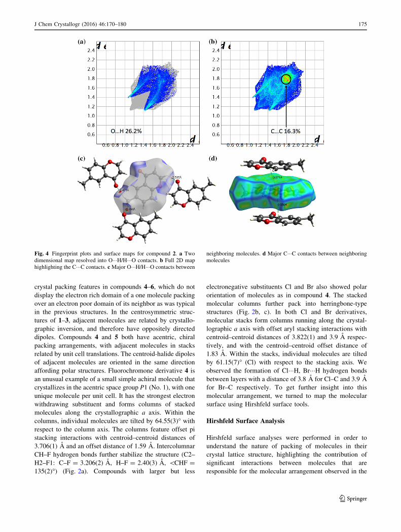
Fig. 4 Fingerprint plots and surface maps for compound 2. a Two
dimensional map resolved into O���H/H���O contacts. b Full 2D map
highlighting the C���C contacts. cMajor O���H/H���O contacts between
neighboring molecules. d Major C���C contacts between neighboring
molecules
J Chem Crystallogr (2016) 46:170–180 175
123
crystalline state. Two dimensional (2D) fingerprints maps
were obtained by calculating the distances from the Hir-
shfeld surface to the nearest nucleus inside the surface (di)
to the outside surface (de) to analyze the molecular inter-
actions around the nearest neighbor molecules. In 2D
maps, green regions shows closer contacts and longer
contacts indicated in blue color. The Hirshfeld surfaces of
the compounds 1–6 were generated over a dnorm range
-0.5 to 1.5 [42]. All surfaces constructed using dnormfunction were illustrated as transparent hollow maps in
order to clearly visualize the benzoannelated c-pyronemoiety inside the surface. The red spots on the surfaces
represent the distances shorter than sum of vdW radii and
blue regions correspond to the distances longer than sum of
vdW radii. The surfaces created using dnorm were used to
highlight the intermolecular O���H, C���H, F���H, Cl���H, andBr���H interactions. Hirshfeld surface maps calculated
using curvedness function shows large regions of green
areas (relatively flat) separated by blue edges represent the
large positive curvature of the molecule. Curvedness maps
were used to analyze the nature of intermolecular C���Ccontacts of each compound.
The two dimensional fingerprint maps and correspond-
ing surfaces for the compound 1 depicted in Fig. 3. Hir-
shfeld analysis suggests that the chromone 1 lattice is
stabilized by three major non-covalent interactions:
hydrogen bonds (O���H), CH–k interactions (C���H) and
aryl-stacking interactions (C���C). There are two major
O���H interactions per molecule that contribute 27.4 % to
the overall interactions. These two interactions are equiv-
alent by symmetry with an average C=O–C distance of
3.170(2) A. Figure 3d and e shows the O���H and C���Hcontacts. The carbonyl oxygen lone pair of one molecule
acts as the accepter and the slightly positive H atom bonded
to carbon next to the oxygen in the pyran ring acts as the
donor. The molecule inside the surface in the Fig. 3f pro-
vides a k-face for the molecule on top to donate a CH–kinteraction with a distance of 2.899(2) A. Simultaneously,
the aryl groups (ArC–H) act as a hydrogen bond donor to
form the second CH–k interaction. The CH–k interactions
correspond to 23.1 % of total contribution. As expected
from literature reports, the aryl-stacking interactions were
less prominent than the O���H and C���H interactions [42].
Figure 3c shows the full 2D map of the molecule, which
also highlights the green area around di = de * 1.8 A and
corresponds to aryl-stacking interactions (8.9 % of the total
contribution). The curvedness surface in Fig. 3f clearly
shows the green flat area and the nearest molecule lying on
top with the distance of 3.57 A, which is well within the
distance for the aryl-stacking interaction.
The predominant interactions in compound 2 are
hydrogen bonds (O���H) and aryl-stacking (C���C) as shownin Fig. 4. Three adjacent molecules participate in the O���Hbonding (Fig. 4c). Two methylene protons acts as
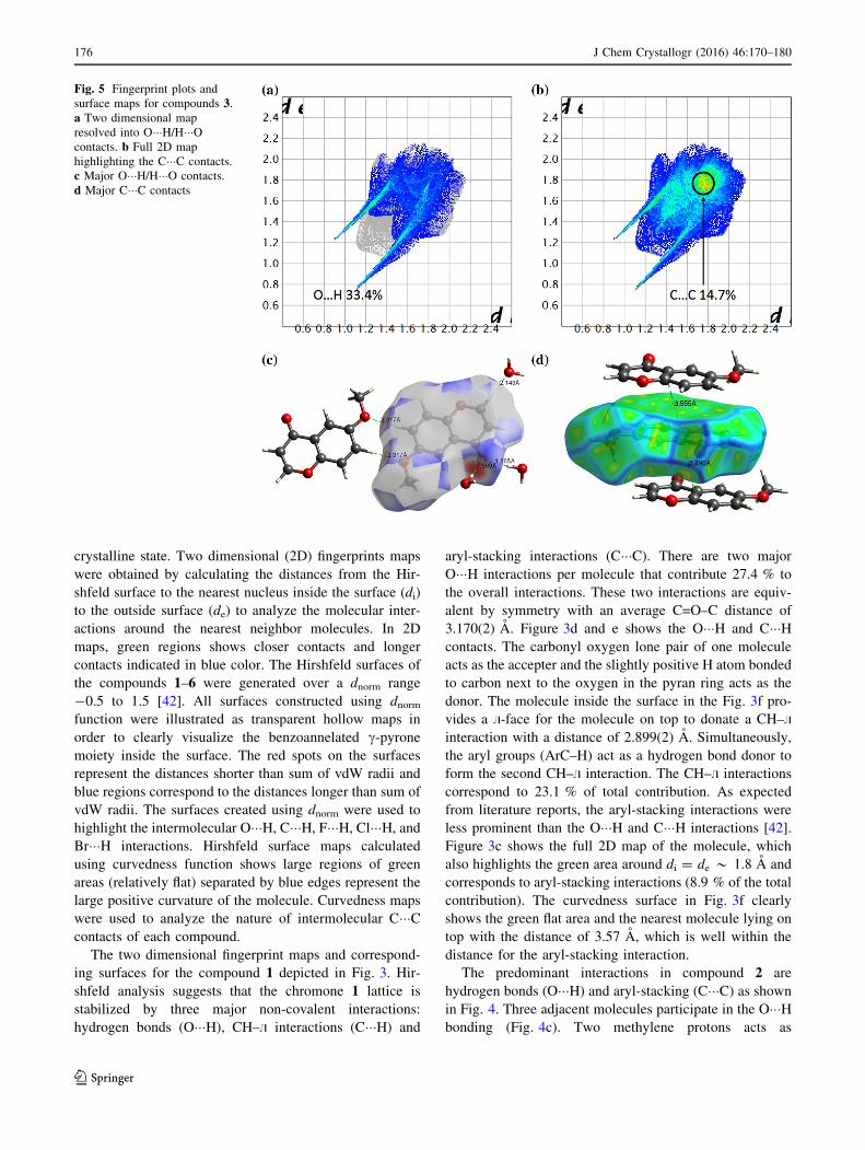
Fig. 5 Fingerprint plots and
surface maps for compounds 3.a Two dimensional map
resolved into O���H/H���Ocontacts. b Full 2D map
highlighting the C���C contacts.
c Major O���H/H���O contacts.
d Major C���C contacts
176 J Chem Crystallogr (2016) 46:170–180
123

hydrogen bond donors to form two O���H interactions with
carbonyl oxygen atoms of two adjacent molecules with the
C=O–C distances of 3.504(2) and 3.541(2) A. The third
O���H interaction is formed between the H on the pyran
ring and the carbonyl oxygen of the nearest molecule with
the C=O–C distance of 3.226(2) A, which is similar to the
O���H interaction observed in the compound 1. The O���Hinteractions constitute 26.2 % of the overall interactions.
The two dimensional map in Fig. 4b shows the C���Ccontacts around the distances of di = de * 1.8 A similar
to compound 1. The curvedness map in the Fig. 4d shows
two neighboring molecules interact with the single mole-
cule to form two aryl-stacking interactions with the dis-
tance of 3.55 and 3.57 A. The percentage contribution is
16.3 %, close to twice as much as calculated for compound
1 which displays only one aryl stacking interaction.
The Hirshfeld analysis suggests that the lattice of
compound 3 is stabilized by hydrogen bonds (O���H) andaryl-stacking (C���C) interactions. There are four significantO���H interactions between one molecule of 3 with three
molecules of water and another molecule of 3 as indicated
by Fig. 5c. The main O���H interactions occur between the
oxygen in the methoxy group and a proton from the ben-
zene ring. These form a stable O���H interaction with the
O–C distance of 3.352(1) A for each O���H interaction.
Two H atoms from two water molecules form two O���Hinteractions with the two lone pairs on the carbonyl oxygen
with the distance of 2.847(2) and 2.850(2) A (C=O–O) for
each interaction. The oxygen atom from the other water
molecule served as the accepter to form another O���Hinteraction with the proton in the pyran ring with the O–C
distance of 3.223(2) A. All together O���H interactions
responsible for 33.4 % to the overall stabilizing interac-
tions which is higher compared to molecule 1 and 2, which
have comparatively fewer O���H interactions. The aryl-
stacking interactions occurred between two neighboring
molecules as indicated by flatness of curvedness map in the
Fig. 5d with distances of 3.56 and 3.49 A. The aryl-
stacking (14.7 %) has a similar contribution to the overall
interaction as molecule 2.
Figure 6 shows the fingerprint plots and surface maps
for 6-fluorochromone (4). Compound 4 has additional F���H
Fig. 6 Fingerprint plots and surface maps for compounds 4. a Two
dimensional map resolved into O���H/H���O contacts. b Two dimen-
sional map resolved to show F���H/H���F contacts. c Full 2D map
highlighting the C���C contacts. dMajor O���H/H���O contacts. eMajor
F���H/H���F contacts. f Major C���C contacts
J Chem Crystallogr (2016) 46:170–180 177
123

Fig. 7 Fingerprint plots and surface maps for compounds 5. a Two
dimensional map resolved to show Cl���H/H���Cl contacts. b Two
dimensional map resolved into O���H/H���O contacts. c Full 2D map
highlighting the C���C contacts. d Major Cl���H/H���Cl contacts.
e Major O���H/H���O contacts. f Major C���C contacts
Fig. 8 Fingerprint plots and surface maps for the 6-bromochromone
6 [36]. a Two dimensional map resolved to show Br���H/H���Brcontacts. b Two dimensional map resolved into O���H/H���O contacts.
c Full 2D map highlighting the C���C contacts. d Major Br���H/H���Brcontacts. e Major O���H/H���O contacts. f Major C���C contacts
178 J Chem Crystallogr (2016) 46:170–180
123

hydrogen bonding interactions in addition to the O���H, andC���C that were observed for compounds 1–3. A single
molecule of 4 interacts with three adjacent molecules
forming four O���H interactions, contributes significantly to
the overall contacts (26.4 %). The interaction forms
between electron poor H atom on the carbon adjacent to F
with the lone pair electron on a neighboring pyran oxygen
shows a C–O distances of 3.478(2) A. The second hydro-
gen bonding interaction is observed between the electron
poor H atom in the pyran ring that interacts with the lone
pair of carbonyl oxygen on an adjacent molecule and
shows a C=O–C distance of 3.340(2) A as indicated in the
Fig. 6d. In addition, two lone pairs on the carbonyl oxygen
of molecule inside the surface act as acceptors for two C–H
hydrogen bonding interactions with two different neigh-
boring molecules displaying C=O–C distances of 3.554(2)
and 3.637(2) A respectively. There are two F���H interac-
tions highlighted in the Fig. 6e which are formed by the H
atom close to carbonyl of one molecule with an F atom in
the nearest molecule at F–C distance of 3.206(2) A. The
overall contribution of F���H contacts are found to be
18.9 %. Two aryl-stacking interactions formed between
molecules showed in the curvedness map in Fig. 6f with a
distance of 3.7 A and a contribution of 12.4 %, a little
higher than in 2 and 3.
Inspection of the Hirshfeld analysis of compound 5
shows marked differences from the fluorinated analogue
4. Here, we observed Cl���H hydrogen bonding as the
main contributor to the packing with an overall contri-
bution of 23.3 % (Fig. 7a) with the O���H hydrogen
bonding motif contributing less (19.3 % in 5 vs. 26.4 %
in 4). There were two significant Cl���H interactions per
molecule with a C–Cl distance of 3.799(2) A (Fig. 7d).
These formed between the Cl atom of one molecule and
the H9 of the nearest neighbor molecule. Two hydrogen
bonds (O���H) observed between the carbonyl oxygen and
H2 atom have similar C=O–C distance of 3.312(3) A. The
offset aryl-stacking interaction also contribute to the
overall packing (10.2 %) and were show a centroid to
centroid distance of 3.82 A.
Hirshfeld analysis was carried out on the reported
crystal structure of 6-bromochromone 6 [36], which
showed similar herringbone-type packing as the chloro
derivative 5. As expected the lattice forms three major type
of interactions with the neighboring molecules. For
hydrogen bonding interactions, the Br���H hydrogen bond is
the major contributor, with 24.5 % overall contribution.
There are two Br���H bonds can be seen between Br and H4
with a Br–C distances of 3.96 A. Next, the O���H hydrogen
bonds form between carbonyl oxygen and the H3 (Fig. 8e)
with the C=O–C distance of 3.32 A, which contribute
17.8 % to the overall packing. Less prominently, we
observed aryl-stacking (C���C) interaction between the pi
surfaces of neighboring molecule (Fig. 8f) with a contri-
bution of 9.3 % and a distance of 3.92 A.
Figure 9 summarizes the contribution of all the non-
covalent interactions in each compound. Compound
6-methoxychromone showed the highest percentage of
O���H contacts (33.4 %) where 6-bromochromone has the
lowest (17.8 %). Among halogen containing compounds
6-bromochromone has the high contribution from X���Hcontacts (24.5 %) while 6-fluorochromone has lowest
(18.9 %). A survey of halide containing small molecules
show that this percentage varies significantly depending on
the type of halogen containing compound analyzed [43,
44]. We observed a great portion of C���H contacts in the
compound chromone (23.1 %) and C���C contacts in the
compound 6-methylchromone (16.3 %). Apart from above
the H���H contacts varies 19–48 % where 6-methylchro-
mone been the highest (47.9 %) and 6-bromochromne
(19.6 %) the lowest.
Conclusions
In summary, we have systematically investigated the
electronic characteristics of simple chromone derivatives
through wide selection of electron donating and electron
groups at the 6-position. Single crystals of each derivative
were successfully grown, their solid-state structures deter-
mined by X-ray diffraction and the major packing inter-
actions that help to stabilize each structure and identified.
We used Hirshfeld surface analysis to further understand,
identify and quantify the interactions that are responsible
for different packing patterns seen in the derivatives.
According to our Hirshfeld analysis, the majority of sta-
bilizing interactions in chromone 1 consist of O���Hhydrogen bonds (27.4 %) and CH-k interactions (23.1 %).
Chromones with electron donating substituents at the
6-position including methyl 2 and methoxy 3, have O���Hhydrogen bonds (26.2, 33.4 % respectively) and offset aryl
stacking interactions (16.3, 14.7 % respectively) as the
major contributors to the overall packing interactions. In 1–
3, the hydrogen bond donors are relatively weak C–H
Fig. 9 Contribution of the various contacts to the Hirshfeld surface
J Chem Crystallogr (2016) 46:170–180 179
123

types. The pairs are oriented with the electron rich aryl
group of one chromone oriented over the electron poor aryl
group of the neighboring molecule. The analysis outcome
of the 6-fluorochromone (4) shows a greater portion of
stabilizing interactions consist of hydrogen bonds; how-
ever, here there are two types of hydrogen bond acceptors
with O���H hydrogen bonds contributing slightly more
stabilizing interactions (26.4 %) than the F���H hydrogen
bonds (18.9 %). In contrast, in lattice structures of
6-chlorochromone (5) and 6-bromochromone (6), the
halogen contributes the larger percentage of stabilizing
hydrogen bonding interactions with Cl���H (23.3 %) and
Br���H hydrogen bonds (24.5 %) versus the O���H hydrogen
bond motif (19.3, 17.8 % respectively). In the future,
comparison of SCXRD analysis and fingerprints plots
generated form Hirshfeld analysis for series of compounds
should help to elucidate trends and provide insight into the
complex process of crystal formation.
Supporting Information
X-ray crystal structures for the compounds 1–5 (CCDC
1415399-1415403) were deposited in the CCDC database.
Acknowledgments This research was supported by the National
Science Foundation CHE-1305136.
References
1. Desiraju GR (2013) J Am Chem Soc 135(27):9952–9967
2. Tiekink ERT (2012) Crystal engineering. Supramolecular
chemistry. Wiley, New York
3. Aakeroy CB, Champness NR, Janiak C (2010) CrystEngComm
12(1):22–43
4. Desiraju GR (2007) Angew Chem Int Ed 46(44):8342–8356
5. Braga D, Brammer L, Champness NR (2005) CrystEngComm
7(1):1–19
6. Hollingsworth MD (2002) Science 295(5564):2410–2413
7. Braga D, Desiraju GR, Miller JS, Orpen AG, Price SL (2002)
CrystEngComm 4(83):500–509
8. Stadler A-M, Lehn J-MP (2014) J Am Chem Soc
136(9):3400–3409
9. Dolain C, Maurizot V, Huc I (2003) Angew Chem Int Ed
42(24):2738–2740
10. Kay ER, Leigh DA, Zerbetto F (2007) Angew Chem Int Ed
46(1–2):72–191
11. Lehn JM (2006) Molecular and supramolecular devices.
Supramolecular chemistry. Wiley, New York, pp 89–138
12. Tian J, Thallapally PK, McGrail BP (2012) Gas storage and
separation in supramolecular materials. Supramolecular chem-
istry. Wiley, New York
13. Makal TA, Li J-R, Lu W, Zhou H-C (2012) Chem Soc Rev
41(23):7761–7779
14. Liu J, Chen L, Cui H, Zhang J, Zhang L, Su C-Y (2014) Chem
Soc Rev 43(16):6011–6061
15. Wu C-D (2011) Crystal engineering of metal-organic frameworks
for heterogeneous catalysis. Selective nanocatalysts and
nanoscience. Wiley, New York, pp 271–298
16. Aakeroy CB, Beatty AM (2001) Aust J Chem 54(7):409–421
17. Desiraju GR (1989) Crystal engineering: the design of organic
solids, vol 54. Elsevier, Amsterdam
18. Verpoorte R, Memelink J (2002) Curr Opin Biotechnol
13(2):181–187
19. Keri RS, Budagumpi S, Pai RK, Balakrishna RG (2014) Eur J
Med Chem 78:340–374
20. Gaspar A, Matos MJ, Garrido J, Uriarte E, Borges F (2014) Chem
Rev 114(9):4960–4992
21. Ishar MPS, Singh G, Singh S, Sreenivasan KK, Singh G (2006)
Bioorg Med Chem Lett 16(5):1366–1370
22. Sakamoto M, Yagishita F, Kanehiro M, Kasashima Y, Mino T,
Fujita T (2010) Org Lett 12(20):4435–4437
23. Sakamoto M, Kanehiro M, Mino T, Fujita T (2009) Chem
Commun 17:2379–2380
24. Hanifin JW, Cohen E (1969) J Am Chem Soc 91(16):4494–4499
25. Hanifin JW, Cohen E (1966) Tetrahedron Lett 7(44):5421–5426
26. Salpage SR, Donevant LS, Smith MD, Bick A, Shimizu LS
(2016) J Photochem Photobiol A 315:14–24
27. Schmidt GMJ (1971) Pure Appl Chem 27:647–678
28. Cohen MD, Schmidt GMJ, Sonntag FI (1964) J Chem Soc
384:2000–2013
29. Cohen MD, Schmidt GMJ (1964) J Chem Soc 383:1996–2000
30. Spackman MA, McKinnon JJ, Jayatilaka D (2008) Crys-
tEngComm 10(4):377–388
31. Parkin A, Barr G, Dong W, Gilmore CJ, Jayatilaka D, McKinnon
JJ, Spackman MA, Wilson CC (2007) CrystEngComm
9(8):648–652
32. McKinnon JJ, Jayatilaka D, Spackman MA (2007) Chem Com-
mun 37:3814–3816
33. Spackman MA, McKinnon JJ (2002) CrystEngComm
4(66):378–392
34. McKinnon JJ, Mitchell AS, Spackman MA (1998) Chem Eur J
4(11):2136–2141
35. Spackman MA, Jayatilaka D (2009) CrystEngComm 11(1):19–32
36. Staples RJ, Lea W (2005) New Cryst Struct 220(3):371–372
37. SMART Version 5.631, SAINT? Version 6.45a (2003) Bruker
Analytical X-ray Systems, Inc., Madison
38. Sheldrick G (2008) Acta Crystallogr Sect A 64(1):112–122
39. Dolomanov OV, Bourhis LJ, Gildea RJ, Howard JAK, Pusch-
mann H (2009) J Appl Crystallogr 42(2):339–341
40. McKinnon JJ, Spackman MA, Mitchell AS (2004) Acta Crys-
tallogr Sec t B 60(6):627–668
41. Wells PR (2007) Group electronegativities. Progress in physical
organic chemistry. Wiley, New York, pp 111–145
42. Seth SK, Sarkar D, Kar T (2011) CrystEngComm
13(14):4528–4535
43. Batsanov AS, Howard JAK, Albesa-Jove D, Collings JC, Liu Z,
Mkhalid IAI, Thibault M-H, Marder TB (2012) Cryst Growth Des
12(6):2794–2802
44. Ling I, Alias Y, Sobolev AN, Raston CL (2010) CrystEngComm
12(12):4321–4327
180 J Chem Crystallogr (2016) 46:170–180
123
![Crystal structure and Hirshfeld surface analysis of diiodido{N′-[(E) …journals.iucr.org/e/issues/2019/07/00/hb7823/hb7823.pdf · 2019-07-26 · 2-yl- N)methylidene]pyridine-2-carbohydrazide](https://img.pdfslide.us/doc/110x75/5ea8c6fa6d35ec45536af8ec/crystal-structure-and-hirshfeld-surface-analysis-of-diiodidona-e-2019-07-26.jpg)


![Synthesis, crystal structure, Hirshfeld surface analysis ...profdoc.um.ac.ir/articles/a/1077952.pdf · halogenating agents [14], oxidative [15,16] and reductive [17] reagents in some](https://img.pdfslide.us/doc/110x75/6062741abd050e0108422dc0/synthesis-crystal-structure-hirshfeld-surface-analysis-halogenating-agents.jpg)
![Crystal structure and Hirshfeld surface analysis of 4,4 ... · 7 H 12 N 6 2+) [VOF 5] 2, which gives insight into the hydrogen-bonding behaviour of [VOF 5] 2 anions when combined](https://img.pdfslide.us/doc/110x75/5fc3a7017e115e5c133f7be6/crystal-structure-and-hirshfeld-surface-analysis-of-44-7-h-12-n-6-2-vof.jpg)