Embed Size (px)
Citation preview
480
ill@0@�ill@!Xl ill@@@ill[i'
!DIVISION !OF /RIESIEARCH 1../EXINGTIJN
October 1977 ·
DEIPART.NIENT OF TRANSPORTATION
CRACKING IN CONTINUOUSLY
REINFORCED CONCRETE PAVEMENTS
James H. Havens
Robert C. Deen
Assaf S. Rahal
W. Vernon Azevedo
JULIAN CARROLL GOVERNOR
CALVIN G. GRAYSON SECRETARY OF TRANSPORTATION
COMMONWEALTH OF KENTUCKY
DEPARTMENT OF TRANSPOR7:4TION
BUREAU OF HIGHWAYS
0/VISION OF RESEARCH 533 SOUTH LIMESTONE
LEXINGTON, KENTUCKY 40508
CALVIN G. GRAYSON SECRETARY
COMMONWEALTH OF KENTUCKY
DEPARTMENT OF TRANSPORTATION Dlvlslon of Research
533 South Limestone
Lexington, KY 40508
October 31, 1977
MEMORANDUM TO: G. F. Kemper State Highway Engineer Chairman, Research Committee
JULIAN M. CARROLL GOVERNOR
H.3.28
SUBJECT: Research Report No. 480; "Cracking in Continuously Reinforced Concrete Pavements;" KYP-71-28; HPR-PL-1 (11), Part III-B
Report No. 480 provides understanding of unwanted, detrimental mechanisms at work in continously reinforced concrete pavements. These insidious1 side effects interfere with the otherwise-expected long-and-enduring, perhaps maintenance-free service-life of this type of pavement.
gd Enclosure cc1s: Research Committee
No.
•
Continuously Reinforced Concrete Pavements
Organization Nama and Address
Division Research Kentucky Bureau of Highways 533 South Limestone Lexington, Kentucky 40508 2. Sponsoring Agency Name c:md Address
15. Notes
Azevedo
Study Title: Continuously Reinforced Concrete P�vement
Technical keport Documentation Page
The objective of this study was to monitor placement and evaluate performance of continuously reinforced concrete pavement with an emphasis on determining the time of cracking and crack interval. This paper reports on the design and construction practice for CRCP in Kentucky. Data on crack frequency and time of cracking is also included in an attempt to further explain the cracking pattern associated with CRCP.
Coi1ti.ri.uo1lSly Reinforced Concrete Pavement (CRCP) Crack Interval Crack Surveys Terminal Joint
Form DOT F 1700.7 IB-72) Reproell)ction of completed page authorized
Research Report 480
CRACKING IN CONTINUOUSLY REINFORCED CONCRETE PAVEMENTS
KYP-71-28; HPR-PL-1 (11), Part III-B
by
James H. Havens Director
Robert C. Deen Assistant Director
Assaf S. Rahal Research Engineer Chief
and W. Vernon Azevedo
Research Engineer
Division of Research Bureau of Highways
DEPARTMENT OF TRANSPORTATION Commonwealth of Kentucky
The contents of this report reflect
the views of the authors who are
responsible for the facts and the
accuracy of the data presented herein.
The contents do not necessarily reflect
the official views or policies of the
Bureau of H ighways. This report does not
constitute a standard, specification, or
regulation.
October I 977
INTRODUCTION The first continuously reinforced concrete
pavement (CRCP) was built by the Bureau of Public Roads in 1921 near Washington, D. C., on the Columbia Pike. In 1925, the Illinois Division of Highways used a continuously reinforced pavement over a sec�i6n of peat bog. Another test road, which included· several continuously reinforced test sections, was placed by the Indiana State Highway Commission in cooperation with the Bureau of Public Roads in 1938. Based on performance of those initial test roads, considerable interest was aroused in several highway departments, and\ additional experimental CRC pavements were constructed in Illinois and New Jersey in 1947 11), in California in 1949 12), and in Texas in 1951 13). By 1959, there had been about 100 miles (160 km) of equivalent, two-lane pavement constructed using CRC concepts. By 1969, the mileage of CRC pavement had increased to over 5,000 miles (8,000 km), and an increasing number of highway and airfield agencies were adopting the CRC pavement as a standard or alternative construction procedure I 4 through 16 ).
CRCP IN KENTUCKY Approximately 7.12 miles (11.5 km) or 29
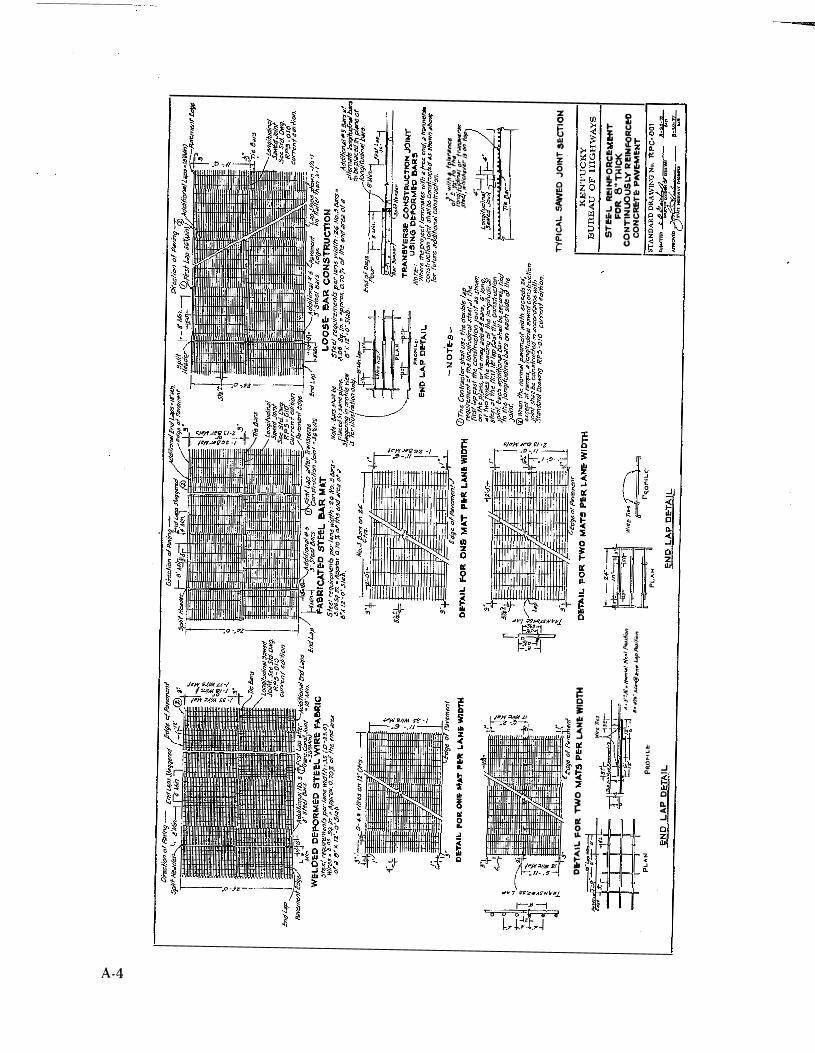
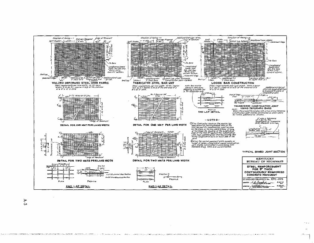
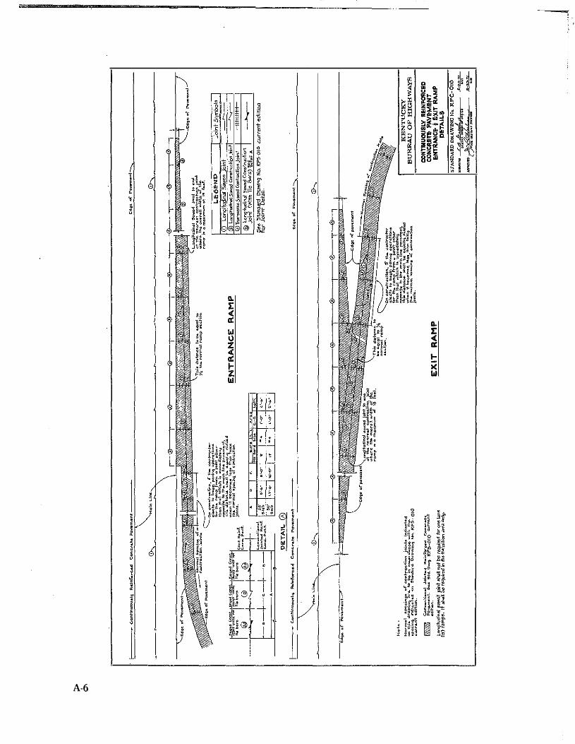
lane-miles (46 lane-km) of continuously reinforced concrete pavement were placed using slip-forms on I 71 in Henry, Trimble, and Carroll Counties [I 71-2(15)37] (Figure 1). Paving was completed there in late 1968 I 17). The slab was 8 inches (203 mm) thick and contained 0.677 percent longitudinal steel placed at a nominal depth of 3 ± 0.5 inches (76 ± 13 mrn) below the surface. No. 5 deformed bars were spaced transversely at 5.5 inches (140 mm). Two inner lanes of mainline pavement extending 4.7 miles (7 .6 km) westbound on I 275 from I 75 in Boone and Kenton Counties [I 275-9(23)8] were built in 1971; the outer lane and Ramp H from I 7 5 southbound onto I 27 5 westbound were completed in 1972 (Figure 2). Other ramps in the I 75 . I 275 junction were not studied. No. 5 bars were used at intervals of 4.75 inches (121 mrn) in the 9-inch (229-mm) slabs. This provided 0.677 percent longitudinal steel for both slab thicknesses. Special provisions and standard drawings applicable to these projects are included in the Appendix.
The m1mmum, expected, 28-day compressive strength for pavement concrete was 3,500 psi (24 MPa), and the minimum, expected, 28-day modulus of rupture was 550 psi (3.8 MPa) when tested in accordance with ASTM C 39 and ASTM C 78. The reinforcement could be deformed steel bars, deformed bar mats, or welded deformed wire fabric. The size, spacing, and laps were indicated on the plans for a specific job. Wide-flange beams and angles in terminal joints conformed to ASTM A 36 and were galvanized after fabrication in accordance with ASTM A 123.
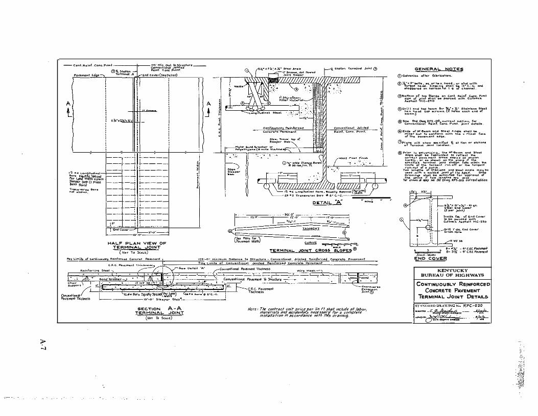
Base and subgrade construction was the same as for conventional pavements. Reinforcement could be installed by pre-setting on chairs or continouous chair bars or be depressed into the fresh concrete -- that is, except when slip-forming. Transverse bars could be positioned either over or under the longitudinal bars, provided that the position was not varied and that a clearance of 3 ± 0. 5 inches (76 ± 13 mm) from the top of the pavement to the steel was maintained. Concrete was placed in one lift. Finishing and curing of CRC pavement were the same as for conventional portland cement concrete construction. Transverse construction joints were installed at the end of each day1s work, when work was terminated for 30 minutes or more, or where the project terminated in a free end. At construction joints, longitudinal bars were required to extend a minimum of 8 feet (2.4 m). Additional No. 5 bars, 3 feet (0.9 m) in length, were placed between the longitudinal bars at the joints. Construction joints were a minimum of 3 feet (0.9 m) beyond a lap, and ali laps were a mi·nimum of 8 feet (2.4 m) beyond construction joints. Terminal joints were a minimum of 125 feet (38 m) from any structure and were also designated where the pavement abutted another pavement. The terminal joint consisted of the necessal)' excavation, the sleeper slab, and the wide-flange beam and angle as then detailed in Standard Drawing RPC-020.

.•
Figure I.
2
I 71 - 2 (15) 37
Location of I 71·2(15)37. Completed in December 1968; 7.198 Miles (11.582 km), 8-inch {203-mm) Slab. Slip-Formed.
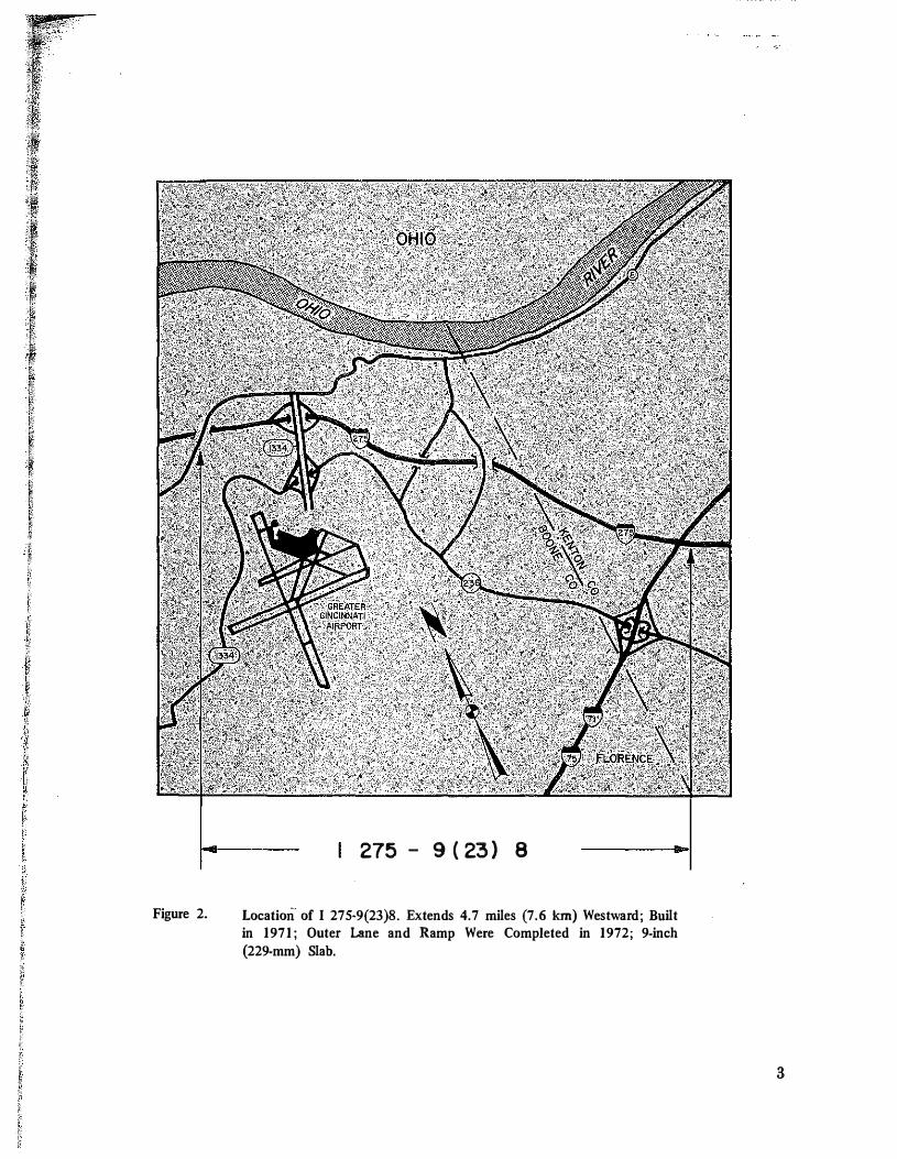
Figure 2.
275 - 9 ( 23) 8
Location· of I 275·9(23)8. Extends 4.7 miles (7.6 km) Westward; Bnilt in 1971; Outer Lane and Ramp Were Completed in 1972; 9-inch {229-mm) Slab.
3
PERFORMANCE Crack surveys were made periodically on I 71 and
I 275; 200 feet (61 m) in each 1,000 feet (305 m) were sampled on I 71; 100 feet (30 m) in each 1 ,000 feet (305 m) were sampled on I 275. Any crack, regardless of size, was counted and recorded. The survey made in July 1969 on I 71 gave an average interval of 5.78 feet (1.76 m) between cracks. In July 1970, another survey was conducted, and the average interval between cracks was 4.14 feet (1.26 m). There was a strong tendency for cracks to occur at intervals at or between
2.5 and 5 feet (0.8 and 1.5 m).
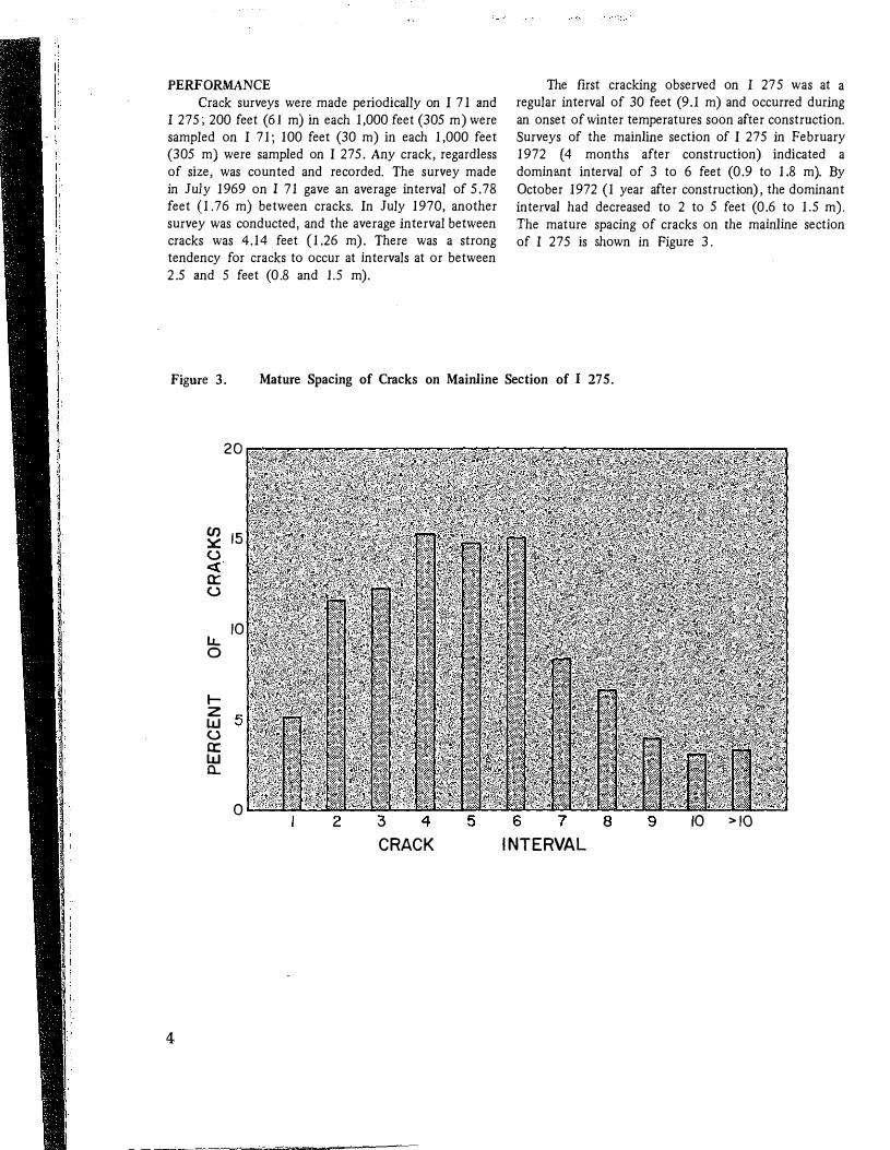
The first cracking observed on I 27 5 was at a regular interval of 30 feet (9.1 m) and occurred during
an onset of winter temperatures soon after construction. Surveys of the mainline section of I 275 in February 1972 (4 months after construction) indicated a dominant interval of 3 to 6 feet (0.9 to 1.8 m). By
October 1972 (1 year after construction), the dominant
interval had decreased to 2 to 5 feet (0.6 to 1.5 m). The mature spacing of cracks on the mainline section of I 275 is shown in Figure 3.
Fignre 3. Mature Spacing of Cracks on Mainline Section of I 275.
20
(f) 15 :.::: u <t 0:: u
10 I.J... 0
1-z 5 w u 0:: w a..
0 2 3 4 5 6 7 8 9 10 >10
CRACK INTERVAL
4
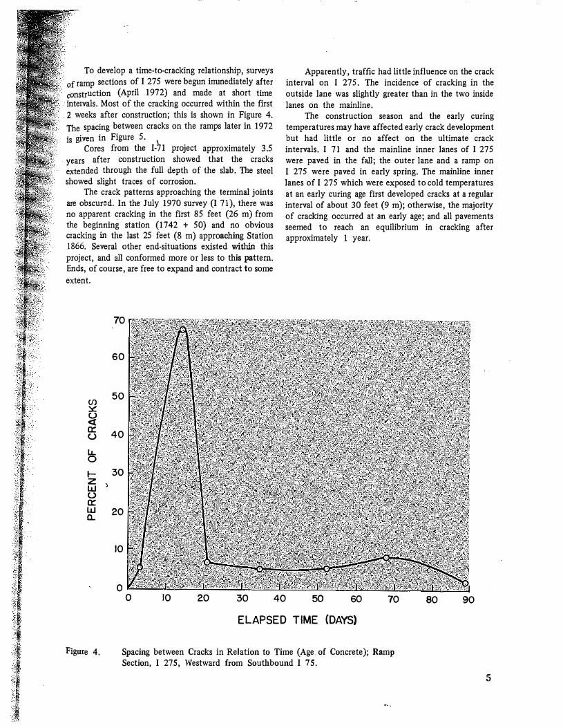
To develop a time-to-cracking relationship, surveys
f ramp sections of I 275 were begun inunediately after �onstruction (April 1972) and made at short time intervals. Most of the cracking occurred within the first z weeks after construction; this is shown in Figure 4.
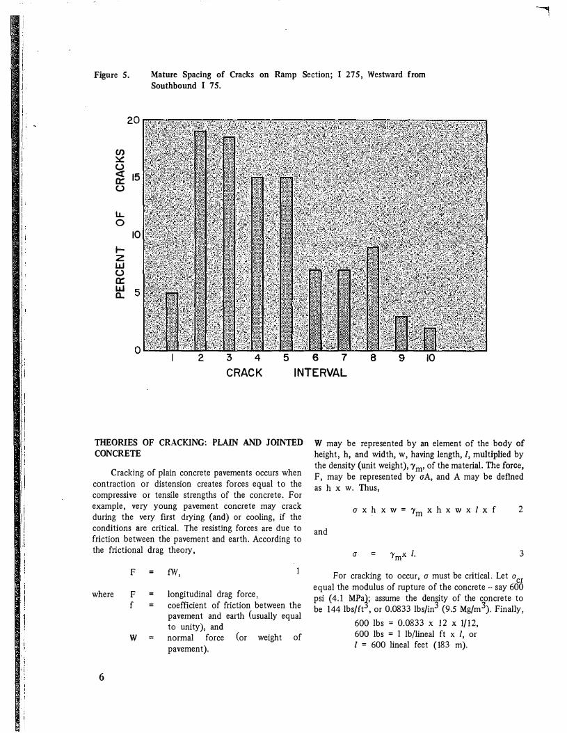
The spacing between cracks on the ramps later in 1972
is given in Figure 5. 1 Cores from the I-71 project approximately 3.5
years after construction showed that the cracks
extended through the full depth of the slab. The steel showed slight traces of corrosion.
The crack patterns approaching the terminal joints are obscured. In the July 1970 survey (I 71), there was no apparent cracking in the first 85 feet (26 m) from the beginning station (1742 + 50) and no obvious cracking in the last 25 feet (8 m) approaching Station 1866. Several other end-situations existed within this
project, and all conformed more or less to this pattern. Ends, of course, are free to expand and contract to some
extent.
(/) :.: (.) <( a:: (.)
LL. 0 1-z w (.) a:: w a.
70
60
50
40
30
20
10
0 0 10 20 30
Apparently, traffic had little influence on the crack interval on I 275. The incidence of cracking in the outside lane was slightly greater than in the two inside lanes on the mainline.
The construction season and the early curing temperatures may have affected early crack development but had little or no affect on the ultimate crack intervals. I 71 and the mainline inner lanes of I 275 were paved in the fall; the outer lane and a ramp on I 275 were paved in early spring. The mainline inner lanes of I 275 which were exposed to cold temperatures at an early curing age first developed cracks at a regular interval of about 30 feet (9 m); otherwise, the majority of cracking occurred at an early age; and all pavements seemed to reach an equilibrium in cracking after approximately I year.
40 50 60 70 80 90
EL APSED TIME (DAYS)
Figure 4. Spacing between Cracks in Relation to Time (Age of Concrete); Ramp Section, I 275, Westward from Southbound I 75.
5
II II jl I: I' I! II II lr i i j, rj
I i <<<
i i I'
Figure 5. Mature Spacing of Cracks on Ramp Section; I 275, Westward from Sonthbound I 7 5.
20
C/) � () <{ 15 a:: ()
1..1.. 0
10 1-z w () a:: w 5 ll.
2 3 4 CRACK
5 6 7 8 9 10 INTERVAL
THEORIES OF CRACKING: PLAIN AND JOINTED CONCRETE
Cracking of plain concrete pavements occurs when contraction or distension creates forces equal to the compressive or tensile strengths of the concrete. For example, very young pavement concrete may crack during the very first drying {and) or cooling, if the conditions are critical. The resisting forces are due to friction between the pavement and earth. According to the frictional drag theory,
F = fW,
where F = longitudinal drag force, f = coefficient of friction between the
pavement and earth (usually equal to unity), and
w = normal force (or weight of pavement).
6
W may be represented by an element of the body of height, h, and width, w, having length, I, multiplied by the density (unit weight), 'Ym• of the material. The force, F, may be represented by a A, and A may be defined as h x w. Thus,
and
a X h X W = 'Ym X h X W X I X f 2
3
For cracking to occur, a must be critical. Let a cr equal the modulus of rupture of the concrete .. say 600 psi (4.1 MPa1; assume the density of the concrete to be 144 lbs/ft , or 0.0833 lbs/in3 (9.5 Mg/m\ Finally,
600 lbs = 0.0833 X 12 X 1/12, 600 lbs = 1 lb/lineal ft x I, or I = 600 lineal feet (183 m).
It is seen that the tensile strength of the concrete in pounds per square inch is equal to the length of pavement in feet which can be mobilized (brought into traction) in both directions about an assumed point (cross section) of reference during contraction. The natural interval between tension cracks, therefore, will be approximately 2 I. There would be at least one crack in each 1,200-feet (365-m) length of pavement. Usually, critical drying-shrinkage or cooling occurs before the concrete achieves ultimate strength. For instance, if new concrete achieves 30 psi (0.2 MPa) tensile strength during the first few hours and undergoes further drying and cooling at night, there may be cracks at 60-feet (18-m) intervals. This is a basis for spacing contraction joints at 50 feet (15 m) or less and for sawing joints before the concrete is 16 hours old. Figure 6 shows a shrinkage crack which was well-controlled by a sawed
joint. Figure 7 shows a crack near a contraction joing which was sawed too late or else the dowels were skewed or were otherwise locked.
Concrete having a compressive strength of 3,000 psi (21 MPa) is capable of pushing 3,000 lineal feet (915 m) of pavement in both directions from a given point. The normal interval between blowups or severely crushed joints would be between 6,000 and 9,000 feet (1,820 and 2,740 m) (considering compressive strength to be 4,500 psi (31 MPa)) if there were no reductions in cross-sectional bearing such as those made by sawed joints. A 25�percent reduction in cross section wouldshorten the interval to between 4,500 and 6,750 feet (1370 and 2060 m). This is a basis for spacing expansion joints approximately one-half mile (0.8 km) (or less) apart.
Figure 6: Normal Shrinkage Cracking, Well-controlled by Sawed Joint; I 64, Louisville-Frankfort; Nov. 1965.
7
Figure 7. Shrinkage Crack. Either the joint was Sawed too Late or the Dowel Bars Locked or Froze (Misaligned).
It is seen that the ability of concrete to npush" is about 10 times greater than its ability to "pull''. This "push-pull" cycling is a daily and seasonal happening, which may or may not involve freeze-thaw phenomena.
·Even apart from any freezing and thawing, push-pull stresses are fatiguing if they exceed approximately 50 percent of their failure values. Fatigue is an insidious type of failure which eventually becomes outwardly and visibly manifested in cracks where the stresses have been most concentrated. This type of deterioration has been identified extensively with sawed- or reduced-section-type joints and called ''D-cracking'' -
but has been mistakenly attributed, by others, to unsound aggregate and to freeze-thaw actions (18. 19).
Whereas weakened-plane-type joints effectively discipline the close-interval cracking due to contraction, the pushing stresses accompanying temperature exapnsion often exceed 50 percent of the critical compressive stress. The thrust force borne by a cross section reduced 25 percent intensifies the stress 1.33 times. Near-critical stresses cause severe fatigue damage. Of course, critical stresses cause explosive shattering or buckling. An increase of l00°F (56°C) in pavement temperature suffices to generate severe compression in a pavement.
8
Figure 8 shows a crack midway between contraction joints which are r'frozen 11 or nlockedn. The direction of traffic is from left to right. Faulting is typically a drop-off. Figure 9 shows a sawed, doweled, contraction joint which is also faulted slightly. Each of these two cases illustrates a tendency to upthrust in the forward direction. Progressive deterioration, such as D-cracking, shattering, etc. is more likely to originate at the sawed joint because the force bears on a reduced cross section. The dowel holes in the concrete must have enlarged somehow under the forces causing faulting.
Figure 10 shows upthrusting at a full-depth concrete patch. The patch, there, is shaped like an inverted T -- that is, the granular base material was removed from under the ends of the slabs, and the whole cavity was refilled with concrete. Upthrusting is evident at the joint between the edge of the slab and the bituminous shOulder.
A cracking phenomenon not yet fully explained is shown in Figure 11 . The separation at the centerline (groove sawed to one-fourth of slab thickness+ 1/2 inch (13 mm)) could not have happened unless accompanied by failure of the tie bars.
e.
Figure 8. Crack Midway between Contraction Joints which Are Frozen or Locked.
Figure 9. Contraction Joint which Is also Faulted Slightly in One Lane.
9
Figure 10. Upthrusting at a Full-Depth, Inverted-T Patch.
Figure II. Separation at a Sawed Centerline Joint; Tie-Bars Were Found Broken.
!0
FATIGUE OF CONCRETE Concrete may withstand an unlimited number of
applications of stress up to 50 percent of its ultimate strength -- some authorities say, up to 55 percent of ultimate strength. From the standpoint of pavement slabs, fatigue is usually inferred to mean overstressing due to bending (flexure). Whereas bending due to live loads and warping due to temperature are normally considered in the design of pavement slabs, overstressing (fatigue) in the axial direction due to thermal expansion (compression) has not been regarded heretofore as being significant to the performance of pavements. Unfortunately, progressive deterioration at sawe� joints has been mistakenly attributed by others to freezing-and-thawing and blamed on poor quality of aggregate -- under the name of D-cracking.
Strength of concrete varies somewhat with the mode and rate of loading and with moisture conditions. A given stress may be slightly more (or less, as the case may be) fatiguing at some times than it is at others. A stress near criticality at a given time and in given conditions may cause catastrophic failure at another time or under slightly different conditions. Nevertheless, fatigue tests in the compression mode have yielded typical S-N diagrams. Antrim and McLaughlin (20) found good correlation between the stress S, expressed as a percentage of compressive strength, and log N, the number of load applications; their equation for air-entrained concrete was as follows:
log N = 20.501 - 0.214 S. 4
It is interesting to note that when N = 1, S = 96; when S is in the range of 50 to 55, N is large.
Fatigue damage generally progresses in three or more stages: the first is insidious (or unseen) and continues until a crack is found (crack initiation); the second involves crack propagation through a subcritical to a critical stage; the third stage is the final fracture. The total fatigue life embraces all stages. As a matter of historical interest to Kentucky, see Reference 21.
THE D-CRACKING PHENOMENON Whereas some commentaries imply that the term
D-cracking in portland cement concrete pavements merely alludes to an early, recognizable symptom of deterioration usually associated with a joint or an edge, others use the term more defmitively: that is, to describe D-shaped cracking patterns conjunctive to a joint or edge.
From the mid-1920's until the late-1940's, both expansion and contraction joints were considered to be necessary to the satisfactory performance of concrete pavements. Several experimental pavements were built without any joints; the natural intervals of cracking were
about 50 feet (15 m) when the concrete contained limestone aggregates and less than 50 feet (15 m) when the aggregate was gravel. The cracking was adjudged to be due, principally, to shrinkage and thermal contraction. Current practices for spacing contraction joints evolved from those experiments. The conception of a contraction joint was a reduced cross section, with or without dowel bars. The depth of the saw cut became D/4 + l /4 inch (6.3 mm), where D is the thickness of the slab. The thinking was that expansion would somehow take care of itself. Prior history indicated that expansion joints did not prevent blowups. The joints filled with incompressible material and ceased to function, anyhow. Wooley, 1945 (22), credited this explanation to Griffin, 1943 (23).
Whereas the experimental pavements without joints contracted and cracked, thermal expansion and closure brought the total cross section into bearing. On the other hand, the sawed contraction joint reduced the bearing area and consequently intensified bearing stresses 1.38 times.
Assuming the coefficient of thermal expansion of concrete to be 5.5 X 10"6 per degree F (9.9 X w-6
per degree C), and the modulus of elasticity to be 5 x 10⁶ psi (34.5 GPa), the stress rise, when fully constrained, would be: Cs liT Es, or 2,750 psi (19.0 MPa). The stress concentrated on the bearing area would be 2,750 x 1.38, or nearly 3,800 psi (26.2 MPa). Normally, pavement concrete is required to have a compressive strength of 3,500 psi (24.1 MPa). Fortunately, most concrete exceeds the strength specified; fortunately, too, the concrete is not fully constrained unless the contraction joints have become filled. Nevertheless, it seems evident that thermal stressing can approach the compressive strength of the concrete at typical contraction joints, Blowups observed have occurred at joints -- not in the slab itself. Blowups most likely occur at joints where the concrete is the weakest.
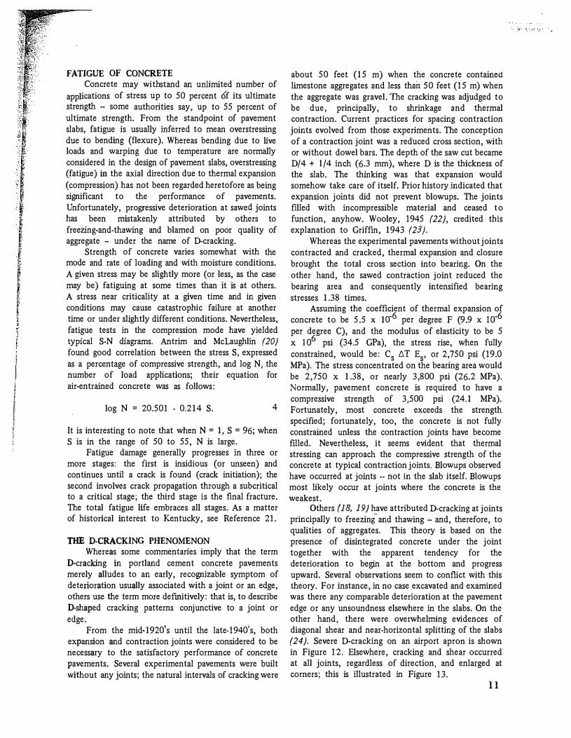
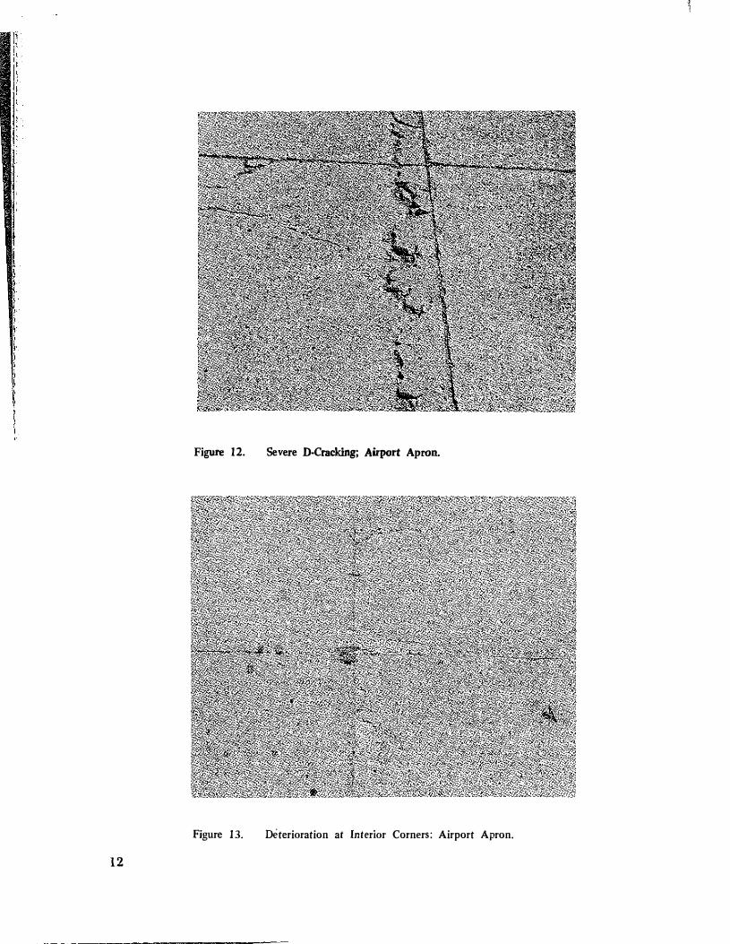
Others (18, 19) have attributed D-cracking at joints principally to freezing and thawing -- and, therefore, to qualities of aggregates. This theory is based on the presence of disintegrated concrete under the joint together with the apparent tendency for the deterioration to begin at the bottom and progress upward. Several observations seem to conflict with this theory. For instance, in no case excavated and examined was there any comparable deterioration at the pavement edge or any unsoundness elsewhere in the slabs. On the other hand, there were overwhelming evidences of diagonal shear and near-horizontal splitting of the slabs (24). Severe D-cracking on an airport apron is shown in Figure 12. Elsewhere, cracking and shear occurred at all joints, regardless of direction, and enlarged at comers; this is illustrated in Figure 13.
ll
l
Figure 12. Severe D·Cracking; Airport Apron.
Figure 13. Dfterioration at Interior Corners: Airport Apron.
12
It is hypothesized, here, that the principal mechanism of deterioration of these situations is overstressing of the bearing area at the joint. The principal thrust is generated by thermal expansion; the eccentricity or direction of the thrust at the bearing surface determines the mode or angle of failure. Warping of the slab or intrusions into the joint may cause uneven bearing. Fatigue is believed to be a contributory cause. Indeed, cracking and deterioration tends to begin at the bottom and is insidious in that way. Fatigued and fractured concrete may be affected by freezing and thawing; however, freezing and thawing is not an essential part of the mechanism hypothesized.
Contraction joints should not be sawed (should not have a reduced cross section); they should consist of a parting or a non-adhering separating panel extending full depth and width and should have dowel bars. This type of joint may be kept in a compressed condition, or nearly so, by the proper design of expansion joints or dual-purpose contraction-expansion joints. The compression material in the joint should provide enough resistancetto closure to push back and restore several slabs in each direction, from a given joints, to their equilibrium or 11null'' position. Limiting the back-pressure of the joint filler to approximately 50 percent of the compressive strength of the concrete would avoid unnecessary overstressing and fatigue of the concrete.
THEORIES OF CRACKING: CONTINUOUSLY REINFORCED CONCRETE PAVEMENTS
Cracking of continuously reinforced pavements has not been fully explained heretofore. There is a pattern or regular interval of cracking which is characteristic of the first cool-down after the maximum heat of hydration has passed. This interval may range between 30 and 60 feet (9 and 18 m) and may occur within 24 hours after construction. A second pattern appears during the first significant rise in temperature during or after curing. This interval depends on the strength of the concrete at the time and the percentage of steel. This interval generally ranges between 2 and 6 feet (0.6 and 2 m). A third pattern develops in the end zone -- that is, from the very ends of the concrete and steel inward and into the slab. To the unaided eye, it may appear that the distance to the first crack is 50 to 100 feet {15 to 30 m). Close inspection affirms the presence of close·spaced (2 to 6 feet (0.6 to 2 m)) cracking as found farther inward and more remote from the end. The mechanism by which these cracks are obscured there, but revealed elsewhere, is explained by the so-called drag theory and yielding of the steel.
Rising-Temperature Theory For a temperature change of t.T, the steel is
strained Cst.T, where C8 is the coefficient of thermal expansion o f steel. Ukewise, the strain in the concrete is Cct.T, where C0 is the coefficient of expansion of concrete. Assuming continuity of strains,
where Es and Ec are the moduli of elasticity of steel and concrete, respectively. For a balance of forces,
6
where A, is the area of steel per uoit of cross-sectional area of pavement. Substituting Equation 6 into Equation 5 and integrating with respect to T, the stress rise per unit length is found to be
t.ac = 1/ [(l/EsA8) + (1/Ec)l (C8 - Cc) (T2 - Tl).
Using Equation 6, the stress rise in the steel is
The total stress rise, a, can be found from
a = t.a t.L,
7
9
where t.L is the length of pavement under consideration. Substituting Equation 9 into Equations 7 and 8 and integrating with respect to L, it is found that
and
[l/T2 - T1)] [(A,/Ec) +
11
13
Equations I 0 and 11 can be used to estimate L for the following typical values. Whereas the extreme range of cycling of pavement surface temperatures is from -20'F" to 145'F (-29'C to 63'C), the temperatures at the depth of the steel range about IOO'F (56'C) between winter and summer. This value of T 2 - T 1 is used as an approximation of the effective, seasonal change in temperature. Estimates of parameters are as follows:
5.5 X 10"6/'F (9.9 X 10"6/'C), 6.5 x 10⁻⁶/'F (11.7 x 10⁻⁶/'C), 5 x 10⁶ psi (34.5 GPa), 30 x 106 psi (206.8 GPa), 0.00677, and IOO'F (56'C).
Recognizing that the distance between cracks may approach 2L, it is found for concrete with a tensile strength of 600 psi (4.1 MPa) that Lc � 30.7 inches (0.8 m). Lc describes the condition for cracking of the concrete; Ls describes the condition for yielding of the steel. Both conditions are met, approximately simultaneously, when 6T � !OO'F (56'C). It may be noted that the maximum tensile force in the concrete iust balances the maximum extension force in the steel. There is no historical basis for balancing these critical forces or for pre-selecting the percentage of steel in this way. Neither is there any historical basis for considering the yield strength of deformed-bar reinforcing steel to be 90,000 psi (620 MPa). Grade 40 or Grade 60 steel surely would have yielded in the 600-psi (4.1-MPa) concrete described above -- that is, 60,000 x 0.00677 � 406.2 psi (2.8 MPa). The analysis suggests that crack intervals typically should be 2.5 feet (0.8 m) or greater but less than 5 feet (1.5 m). This compares favorably with observed crack intervals. These intervals occurred with about equal frequencies. The frequency graphs do, in fact, appear to be truncated in a way suggesting the existence of bi-modal trends. Bond-Strength Analogy
The force in a steel bar at the yield point is asyA,· To develop sufficient anchorage in concrete to utilize the full force of the bar without pulling out, the bar would have to be embedded a length equal to about 40 diameters. To derive the bond strength needed, let
asyAs � J1 X � X /S 12
where J1 � bond strength needed (psi) J1 asy x Ds/4/s, � � �erimeter of bar (in.), a8y x 1rD sfr � J1 x nDs, x Is, and Ds � diameter of bar (in.).
14
When X,v is 60,000 psi (410 MPa), Ds is 0.625 inch (16 mmJ, and Is is 40 diameters, 1-' � 375 psi (2. 6 MPa). When asy
� 90,000 psi (620 MPa), Ds is 0.625 inch (1.6 mm), and Is is 40 diameters, 1-' � 625 psi ( 4 . 3 MPa). Forty diameters i s a rule-of-thumb figure. Contrarywise, the allowable bond stress is generally taken to be 350 psi (2.4 MPa), which in the above case could mobllize a stress of 56,000 psi (386 MPa) i n the No. 5 bar. Forty diameters of a No. 5 bar is 25 inches (0.6 m).
This analogy implies that if a continuously reinforced pavement were pre-cracked at intervals o f 40 x Ds and were floated and stretched -- that is, pulled uniformly at the tendons, there would be a chance that yielding of the steel and widening of cracks could occur with great regularity. On the other hand, if the concrete were not pre-cracked and the pavement were stretched by pulling the steel, the steel (if capable of withstanding a greater force than the concrete) would transfer force into the concrete in relation to the depth of embedment. The force in the external portion of the tendon would equal the force in the internal portion of the tendon plus the force in the concrete. The first crack may occur at any point farther than Is from each end. Further stretching under the sustained force will induce cracks at an eventual interval ranging between Is and 2/s.
The bond-strength analogy parallels the rising�temperature theory described previously insofar as crack spacing is concerned. The motivating force is more readily visualized as arising from temperature distension of the steel-- in which case no external force is required. Bond strength, or resistance to slip, was called the "slip modulus" by Shrader (25).
APPLICATION OF DRAG THEORY TO CONTINUOUSLY REINFORCED PAVEMENTS
Before close-interval cracking occurs, any thermal contraction, due to down-cooling, tends to shorten the pavement. If the contration were free and unrestrained, the steel would contract slightly more than the concrete· and this tightening of the tendons would bring th; concrete into compression. A pavement resting on earth resists expansion and contraction, as described before. The drag resistance balances the combined tensile forces in the steel and concrete until the stress rises in the concrete to the critical level and the concrete cracks. The steel may or may not have yielded when the concrete cracks. When the concrete cracks, the forces tend to transfer to the steel and to induce yielding in the steel then and when further contraction ensues.
The length of pavement which generates a drag force equal to the yield strength of the steel is
asy x percent steel/100. 13
When a : 60,000 psi (414 MPa) and percent steel: 0.617, then I: 406.2 feet (104 m); when asy
: 90,000 psi (620 MPa), I : 609.3 feet (186 m). If the concrete is already cracked at close intervals,
as explained by rising-temperature situations, the steel alone determines the distance from an end where the drag forces cause yielding of the steel and widening of the cracks. For mild steel, this would be about 400 feet (120 m); for high-strength steel, this would be about 600 feet (185 m). This introduces an apparertt mismatch of logic inasmuch as the observed distance. to the first apparent crack has been in the order of 30 to 100 feet (9 to 30 m). Beyond the first crack, the apparent interval shortens progressively until the normal, short, regular interval becorpes established. However, the first down-cooling or curing shrinkage may occur before bond develops between the steel and concrete. For instance, concrete having a jensile strength of 30 to 50 psi (0.2 to 0.35 MPa), would crack at 30- to 50-foot (9- to 15-m) intervals and crack later at 2.5- to 6.0-foot (0.8- to 1.8-m) intervals. Only the earliest shrinkage cracks would be at all apparent to the observer -- and they might be more so farther inward from the end.
Two mechanisms superimpose at the end. The close-interval cracking has been demonstrated experimentally to be independent of position in a pavement and to be dependent upon the characteristics of the steel and concrete.
Whereas the very first cracking may occur at intervals of 30 to 50 feet (9 to 15 m) and whereas close-spaced cracking must await the development of nearly full strength of the concrete and a critical rise in temperature, close-spaced cracks will not be readily apparent near the end of the slab. However, if the tendons at the end of a slab were pulled, the interval between cracks would be close-spaced; but the crack width would be greatest nearest the end and would diminish farther inward into the slab and as drag resistance rises in proportion to distance.
BUCKLING Thermal compression in a pavement occurs when
the temperature rises and when free expansion is not permitted because of natural or imposed constraints. Constraints may be partial or complete. The actual distension or elongation together with any further elongation which would occur upon removal of any constraints is equal to the free expansion. That portion of the expansion which would occur if constraints were removed is virtual expansion, and that portion of the strain is virtual strain. The product of this strain and the modulus of elasticity is stress.
A plain concrete pavement undergoing a J00°F (56°C) rise would have a free expansion of about 3 feet (5.5 X 10·6 x 100°F X 5,280) per mile (0.57 m per km). If completely constrained, the stress rise would be about 2,750 psi (19 MPa) -- that is, 5.5 x 10·6 X 100°F
x 5 x 10⁶ Indeed, this stress rise alone is likely to exceed 50 percent of the compressive strength of the concrete and is, therefore, fatiguing to the concrete. Extreme effects at points of weakness and( or) reduced sections have been described previously. An overthrust of 3 feet (0.9 m) or an upthrust or arching of slabs could occur. This is a form of buckling.
A continuous strand of reinforcing steel undergoing a 100°F (56°C) rise would have a free expansion of 3.4 feet (6.5 X 10"6 X 100°F X 5,280) per mile (0.6 m per km) -- that is, approximately 0.4 feet per mile (7 6 mm per km) greater than the expansion of concrete. S-shaped bends or laps of several inches (mm) have been noted in instances where continuously reinforced pavements have blown up or shattered.
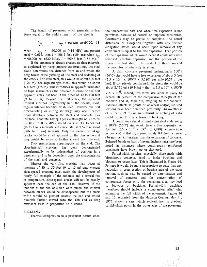
Partial-width patches, especially those made with bituminous 'concrete, tend to invite buckling and blowups to occur later. This is illustrated in Figure 14. Perhaps it would be more appropriate to state that any reduction in cross section or bearing area of the cross section, such as may be caused by deterioration and removal of concrete and the concentration of compressive forces onto the remaining area may lead to blowups or buckling. Partial-width patching, therefore, should include a compression relief joint extending the full width of the pavement. Figures 14 and 15, reprinted from the Madison Courier, May 21, 1977 shows a case which evolved from a previous parti�-width patch in the outer edge of the pavement.
15
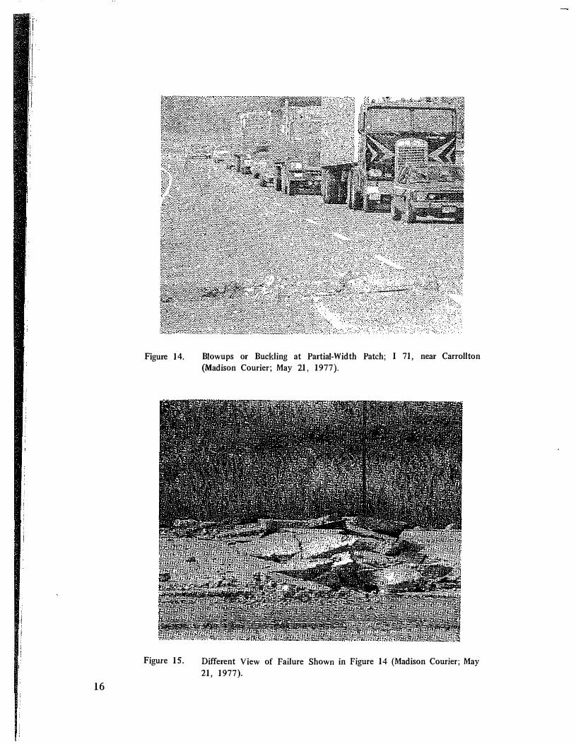
Figure 14.
Figure 15.
16
Blowups or Buckling at Partial-Width Patch; I 71, near Carrollton (Madison Courier; May 21, 1977).
Different View of Failure Shown in Figure 14 (Madison Courier; May 21, 1977).
SIMULATIONS Inasmuch as the theory attributing close-spaced
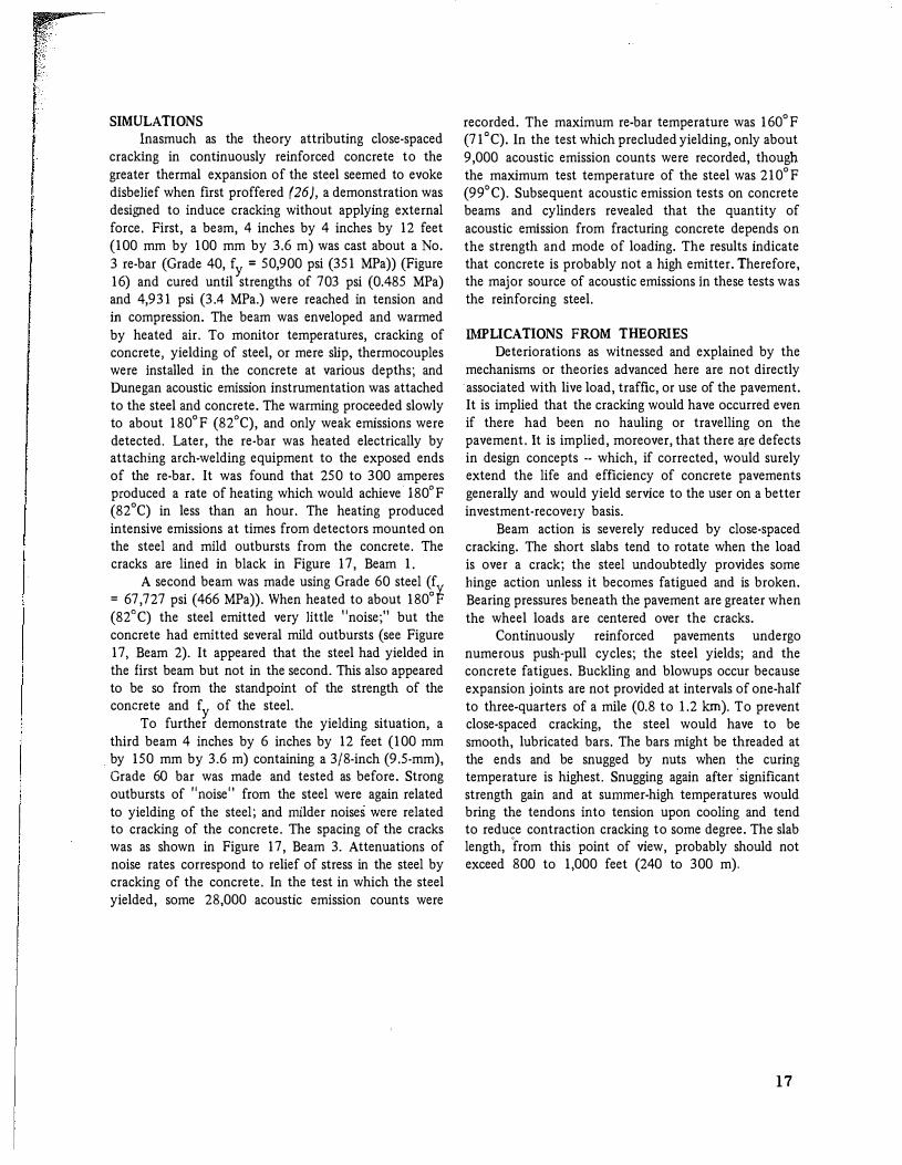
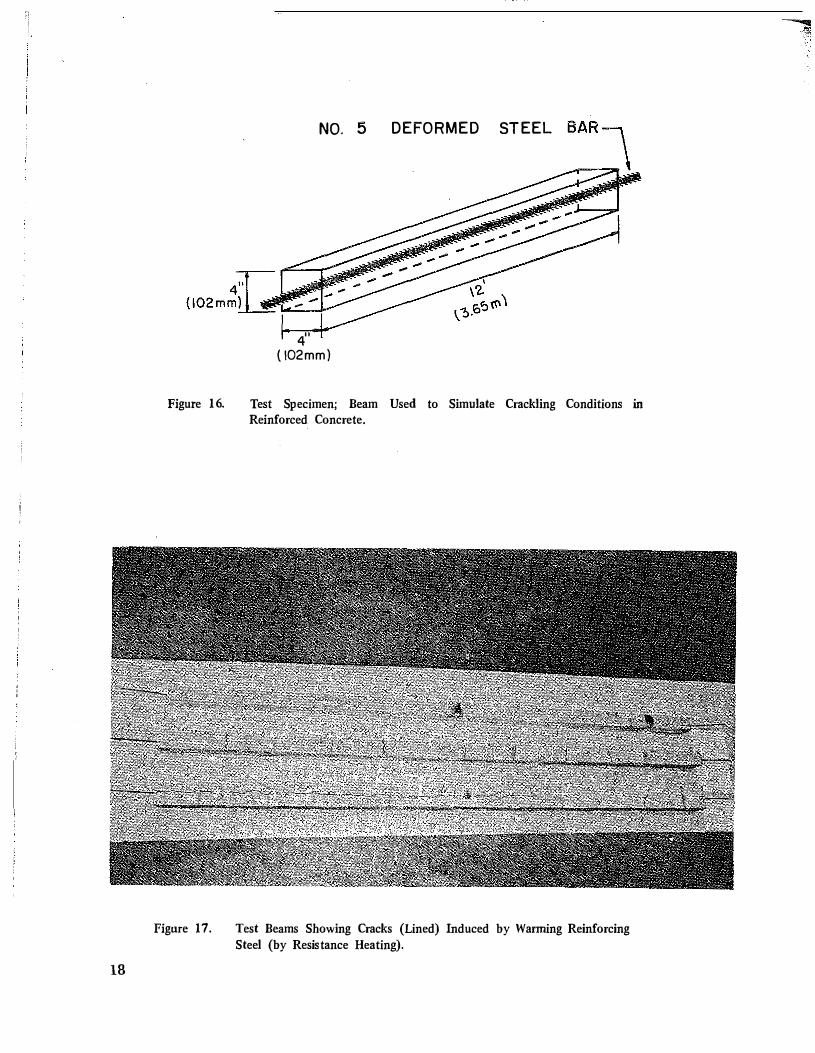
cracking in continuously reinforced concrete to the greater thermal expansion of the steel seemed to evoke disbelief when first proffered (26), a demonstration was designed to induce cracking without applying external force. First, a beam, 4 inches by 4 inches by 12 feet (100 mm by 100 mm by 3.6 m) was cast about a No. 3 re-bar (Grade 40, fy = 50,900 psi (351 MPa)) (Figure 16) and cured until strengths of 703 psi (0.485 MPa) and 4,931 psi (3.4 MPa.) were reached in tension and in compression. The beam was enveloped and warmed by heated air. To monitor temperatures, cracking of concrete, yielding of steel, or mere slip, thermocouples were installed in the concrete at various depths; and Dunegan acoustic emission instrumentation was attached to the steel and concrete. The warming proceeded slowly to about 180°F (82°C), and only weak emissions were detected. Later, the re-bar was heated electrically by attaching arch-welding equipment to the exposed ends of the re-bar. It was found that 250 to 300 amperes produced a rate of heating which would achieve l80°F (82°C) in less than an hour. The heating produced intensive emissions at times from detectors mounted on the steel and mild outbursts from the concrete. The cracks are lined in black in Figure 17, Beam I.
A second beam was made using Grade 60 steel (f = 67,727 psi (466 MPa)). When heated to about 180°P (82°C) the steel emitted very little "noise;" but the concrete had emitted several mild outbursts (see Figure 17, Beam 2). It appeared that the steel had yielded in the first beam but not in the second. This also appeared to be so from the standpoint of the strength of the concrete and fy of the steel.
To further demonstrate the yielding situation, a third beam 4 inches by 6 inches by 12 feet (100 mm
. by 150 mm by 3.6 m) containing a 3/8-inch (9.5-mm), Grade 60 bar was made and tested as before. Strong outbursts of 11Tioise11 from the steel were again related to yielding of the steel; and milder noises were related to cracking of the concrete. The spacing of the cracks was as shown in Figure 17, Beam 3. Attenuations of noise rates correspond to relief of stress in the steel by cracking of the concrete. In the test in which the steel yielded, some 28,000 acoustic emission counts were
recorded. The maximum re-bar temperature was 160°F (71 °C). In the test which precluded yielding, only about 9,000 acoustic emission counts were recorded, though the maximum test temperature of the steel was 210°F (99°C). Subsequent acoustic emission tests on concrete beams and cylinders revealed that the quantity of acoustic emission from fracturing concrete depends on the strength and mode of loading. The results indicate that concrete is probably not a high emitter. Therefore, the major source of acoustic emissions in these tests was the reinforcing steel.
IMPLICATIONS FROM THEORIES Deteriorations as witnessed and explained by the
mechanisms or theories advanced here are not directly ·associated with live load, traffic, or use of the pavement. It is implied that the cracking would have occurred even if there had been no hauling or travelling on the pavement. It is implied, moreover, that there are defects in design concepts -- which, if corrected, would surely extend the life and efficiency of concrete pavements generally and would yield service to the user on a better investment-recovery basis.
Beam action is severely reduced by close-spaced cracking. The short slabs tend to rotate when the load is over a crack; the steel undoubtedly provides some hinge action unless it becomes fatigued and is broken. Bearing pressures beneath the pavement are greater when the wheel loads are centered over the cracks.
Continuously reinforced pavements undergo numerous push-pull cycles; the steel yields; and the concrete fatigues. Buckling and blowups occur because expansion joints are not provided at intervals of one-half to three-quarters of a mile (0.8 to 1.2 km). To prevent close-spaced cracking, the steel would have to be smooth, lubricated bars. The bars might be threaded at the ends and be snugged by nuts when the curing temperature is highest. Snugging again after
'significant
strength gain and at summer-high temperatures would bring the tendons into tension upon cooling and tend to reduce contraction cracking to some degree. The slab length, from this point of view, probably should not exceed 800 to 1,000 feet (240 to 300 m).
17
18
NO. 5 DEFORMED STEEL
4" ( \02mm)
Figure 16. Test Specimen; Beam Used to Simulate Crackling Conditions in Reinforced Concrete.
Figure 17. Test Beams Showing Cracks (Lined) Induced by Warming Reinforcing Steel (by Resistance Heating).
-'11
REFERENCES 1. W. Van Breeman, Ten· Year Report on
Experimental Continuously Reinforced Concrete Pavements in New Jersey, Bulletin 214, Highway Research Board, 1959.
2. B. Tremper, Continuously Reinforced Concrete Pavements in California after Eight Years Service, Bulletin 214, Highway Research Board, 1959.
3. M. D. Shelby and B. F. McCullough, Experience in Texas with Continuously Reinforced Concrete Pavement, Bulletin 274, Highway Research Board, 1960.
4. W. R. Woolley, Design of Continuously Reinforced Concrete Pavement, Bulletin 181, Highway Research Board, 1958.
5. R. L. Schiffman, I. J. Taylor, and W. J. Eney, Preliminary Report on Continuously Reinforced Concrete Pavement Research in Pennsylvania, Bulletin 181, Highway Research Board, 1958.
6. F. C. Witkoski, and R. K. Shaffer, Continuously Reinforced Concrete Pavement In Pennsylvania, Bulletin 214, Highway Research Board, 1959.
7. William Zuk, Analysis of Special Problems In Continuously Reinforced Concrete Pavements, Bulletin 214, Highway Research Board, 1959.
8. J. D. Lindsay, A Ten· Year Report on the Illinois Continuously Reinforced Concrete Pavement, Bulletin 214, Highway Research Board, 1959.
9. G. R. Cudney, An Expeninental Continuously Reinforced Concrete Pavement In Michigan, Bulletin 274, Highway Research Board, 1960.
10. B. F. McCullough and W. B. Ledbetter, LTS Design of Continuously Reinforced Concrete, Transactions, American Society of Civil Engineers, Vol 127, 1962.
11. R. H. Nixdorf and H. A. Lepper, Jr., Maryland Investigation of Continuously·Reinforced Concrete Pavement, 1959-64 Strain Observations, Civil Engineering Department, University of Maryland, 1964.
12. T. C. Teng and J. 0. Coley, Continuously Reinforced Concrete Pavement Observation Program, Mississippi State Highway Department, 1968.
13. J. E. Burke and J. S. Dhamrait, A Twenty· Year Report on the Illinois Continuously Reinforced Pavement, Record 239, Highway Research Board 1968;
14. B. F. McCullough and H. J. Harvey, A Statewide Delfection Study of Continuously Reinforced Concrete Pavement In Texas, R ecord 239, Highway Research Board, 1968.
15. Continuously Reinforced Concrete Pavement, Continuously Reinforced Pavement Group, 1968.
16. K. H. McGhee, Experience With Continuously Reinforced Concrete Pavements in Virginia, University of Virginia, August 1974.
17. R. C. Deen, Continuously Reinforced Concrete Pavement, Bulletin 99, College of Engineering, University of Kentucky, June 1972.
18. Interim Report on D·Cracking of Concrete Pavements in Ohio, Portland Cement Association, March 1972.
19. V. E. Bukovatz, C. F. Crumpton, and H. E. Worley, Study of D·Cracking in Portland Cement Concrete Pavements, State Highway Commission of Kansas 1973; also Kansas Concrete Pavement as Related to IJ..Cracking, Record 525, Transportation Research Board, 197 4.
20. J. Antrim and J. F. McLaughlin, A Study of the Fatigue Properties of Air-Entrained Concrete, Report No. 26, Joint Highway Research Project, Purdue University; October 1958.
21. L. E. Gregg, Experiments with Air Entrainment in Cement Concrete, Bulletin No. 5, Engineering Experiment Station, University of Kentucky, September 1947.
22. W. R. Woolley, Suggested Design for a Continuously Reinforced Concrete Pavement with No Joints, Public Roads Administration, 1945.
23. H. W. Griffm, Transverse Joints in the Design of
Heavy Duty Concrete Pavements, Proceedings, Highway Research Board, 1943.
24. J. H. Havens; The D·Cracking Phenomenon: A Case Study for Pavement Rehabilitation, Kentucky Bureau of Highways, Division of Research, April 1976.
25. W. D. Shrader, Distribution of N�gative Moment Reinforcement in Reinforced Concrete T and Box Girder Bridge Deck Slabs, Ph.D. Dissertation, College of Engineering, University of Kentucky 1972.
'
26. J. H. Havens, Memo Report, Kentucky Department of Highways, December 8, 1970.
19

KENTUCKY DEPARTMENT QF HIGHWAYS SPECIAL PROVISION NO. 6 J - B
CONTINUOUSLY REINFORCED CONCRETE PAVEMENT
This Spec i al Provision shall be applicable only when indicated in the plans or proposal; and shall !:lupersorle :\ll conflict ing requirements of the Department's Standard Specifications for Road and Bridge Con!!trudion, othe"l' Spec ial Provision�. the plans, and the Standard Drawings. Article and Section references herein are to the Department ' s 1 96 5 S t a nda rd
Specifications.
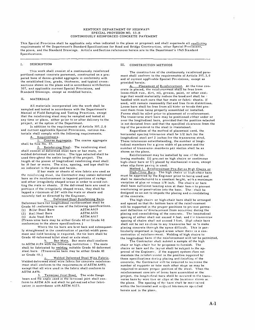
I. DESCRIPTION
' T h i s work shall consist of a continuously reinforced portland cement concrete pavement, constructed on a prepared base of dens e - graded aggregate in conformity with the established line, grade, thickne s s , and typical crosssections shown on the plans and in accordance with Section 3 0 7 , an¢ applicable current Special Provisions, and
St.andard Drawi n g s , except as modified herein,
ll. MATERIALS
A!l materials incorporated into the work shall be sampled and tested in accordance with the Department's Manual of Field Sampling and Testing Practices, except that the reinforcing steel may be :;ampled and tested at any time or plac e , either pl'ior to or after delivery to the project, at the option of the Department.
In addition to the requirements of Artide 307._2. 0 and current applicable Special Provisions, various materials shall comply with the following requirements.
A. Requirements. 1. Coarse Aggregate. The coarse a-ggregate
shall be Size No. 57. 2. Reinforcing Steel. The reinforcing steel
shall consist of deformed steel bars or bar mats, or welded derormed wire fabric. The type selected shall be used thronghout the e ntire length �f the project. The l ength of !he pieces of longitudinal reinforcing steel shall be 16 fee1 or more, The s i :>. e , spacing, and laps shall be a s indicated in the plans and herein ,
If bar mats or sheets of wire fabric are used as t!-:.c reinforcing st.: .::l , Lht: Contractor may install deformed bars as tl-e reinforcement in tapered portions of ramps and other irr eg�1hi.rly s haped areas in order to avoid cutting the )T'ats or sheets . If the def<•rmed bars are used in porti qns "f the irre gularly shaped a r e a s , they shall be lapped a ninimum of 24" with the mats or sheets and s e curely tied as directe:f by the Engineer.
a. D eformed Steel Reinforcing Bars.
Deformed bars for longitudinal reil'lforcerrient shall be Grade 60 .:onforming to one of the following speciHcations. ( I ) Bi llet Steel Bars ASTM A 6 1 5 { 2 ) RaiJ Steel Bars ASTM A616 ( 3 ) Axle Steel Bars ASTM A 6 1 7 (Trans�·erse bars may be either G r ... d e 4 0 o r Grade 6 0 conforming to the above s p e c ifications. )
Where the tie bars are bt•nt back and subsequently strai ghtened in the construct i on of partial-width pavement and Jield bending is r e qu ired , the tie bars shall be Grade 4 0 deformed billet steel or axle steel.
b . Bar Mats. Bar mats shall conform to ASTM A l 8 4 with the following re:;triction : The mats shall be fabricated by welding suitable Grade 60 deformed steel bars. (Transverse bars may be either Grade 40 or Grade 110 . )
' · Welded Deformed Steel Wire Fabric. '\Velded deformed steel wire fabric for concrete reinforcement shall conform to the requiremeJ;�tS of ASTM A497; except that all wire used i n the fabric shall conform to ASTM A496.
J. T e rm inai Joint SteeL The wide flange beam and the anf:le l1 S e d in the te rm i nal joint shall con�
form to ASTM A36 and shall b e galvani zed after fabricatiol'l in accordance with ASTM A l Z 3 .
III. CONSTRUCT�ON METHODS
The construd�on of lhe cpntinuously r e i nforced pavtment shall conform to the requirements of Article 3()7. 3. 0 and of cu_rrent app)h;able Special Prc.vision!l, except as provided herein.
A. Plac e ment of Rt• inforccr.lent. At the t i n1e con-crete is placed, tha rr.inforc�?·ment shall be fre e (rom loose-thick rus1., dirt, oil, g r e a s e , paint, or other coal-in gs that would materially reduce the hom� am\ shall be ·
handled with such care that har mats or fabri•' Sheets, if used, will remain reasbnably flat and free fr<•m distortions. Loose bars shall b e free from all kinkr: or hr.nds that prevent them from being p·roperly a s sembled o r installed, Forms shall be oil('d priGr to placement of n�1nforcement. The trans\•erse sterl b<�rs may be positioned ('ither under or over the longitudinal bars, provided that the p9sition selected
is not deviated frow and that the specHied ct .. arance from the top of the pave mr-nt to the steel iJ.; inaintainerl.
Regardless of the method of placerrieilt 11scd, the horizontal spac inp: tnlcrances shall be 1 /2 iiu·h !or the longitudi11al sled anr\ 2 inches fnr the tr_ansverse stl'el. These tolerances notwithstanding, the number oi longitudinal members for a givfln width of pan�m�nt "nd the number of transvers" mer;;b.-,rs p � r station :;;hall be as s hown on the plans .
Reinforcement may b e installed by one d the following methods: ( I ) pre-set on high chairs or contim1ous high- chair bars or- (;":) placed by mechanical n'eans, except when slip-form paving is used.
Method 1. Rcinforce.ment Pre-Set on H•gh Chairs or Hieh-Ch,>ir B a r s . T h::: high .:hairs u r h i �h- cha i r bars
must be approved by the Engineer prior to behg used and shall be manufactur£'d to a constant he ight, w i · h a maximum variation of plus Clr rr1i nus 1 / 8 i nch . The chai�s or bars shall have sufficient hearing area at their base " to prevent overturning or penetJ·ation into the base. The ·: shall be designed so a s not to impede the- placing and cn�s olidating of the concrete.
The high chain or high-chair bars shall be arranged and spaced so that th.� bottom bars of the reinf'"lrcement will be supported in the proper pos itions to prt·\·e_nt permanent deflection or'diStllacenlent from occu_rrinj: during: the placi ng and con sol idating o[ the conc rete . Th,� long itudi nal spacing of either shall not exceed 4 feet, and t'''"' t ran s \'Cr S P. spacing of chairs shall not e x c e ed 3 r.�..,t. H i g t -chair bars shall not be s e t s o close to any transverse bar ;;s �o make placing concrete thrn•tgh the space d ifficult . 1 hi s is particnlarly important it1 lapped areas where the r .- i s a concentraticm of r<:inforcE·ment. Weldipg of hi gh chairs to the longitudinal bars ,,f the reinforcement will root be permi�ted.
The Contractor �hall submi t a sample of the high chair or high- c ha ir h;>r hi:' proposes to furnish. The
chairs or bar�> anrl th,. l a y (out shall be· subject tn the approval of the Engine� r , lf the suppor� systern dO .. s not maintain the rdnron·emf.'nt in the position requirt•d b�' these spec i fication s durinp; placing anrl f i n i s h i n.e o:· the concrete, the Contract"r will he required to itn· r e � s e the number of support.:;; or take such other st('ps as may be required to as sur.., propel· pos-iti on of th<' st£>el. When the reinforcement cO\'lS ists of loOS!;! bars a s sen1blcd or. the project, the lon�o:itlodin;:;l bars shi'lll b(· S t>c ured to the tran s verse bars b;' wire t i t·s or clips at the loctltio:J� �bo• ... ·n or. the plans. The spacing of t�<"' bars sha! l be m<t;_,_;:a[:'led within the hor iz ontal and V{· r.t k<Jl tol{·ra n c: r s sp,·-:lfied herein and in the plan .- .
A-1
Method 2. Reinforcement Placed by Mech.;nical Means. The reinforcement shall be tied as shown
on the plans and as required b)r this Special Provision prior to being deposited on the surface of the concrete. The methods and equipment used to depress the reiniorcement into the concrete shall not weaken or otherwise alter the concrete, or the laps, joints, or the tied interse<;tions of the longitudinal and the transverse bars.
The reinforcement shall be embedded to the proper depth in the conc'rete by means of a machine approved by the Engineer, ,_Embedment of the reinforcing steel shall be performed in such a manner that the concrete shall show no segregation attributable to the embedment operation. The machine shall be operated in such a manner that it does not drag the reinforcement.
II the machine shows any tendenc:y to displace the reinforcement longitudinally, the Contractor, with the approval of the Engineer and at no additional cost to the Department, shall (I) tie the laps more securely if it can be demonstrated that this will prevent the displacement "and assure the proper lap, or (2) halt paving operations until the machine is properly adjusted or another machine is furnished which will operate in a satisfactory manne_r, or (3) install the reinforcement by Method 1 .
The machine shall b e operated in such a manne r that the concrete "will not be excessively vibrated or otherwise manipulated. If the machine "emploY-s a grid-type depressor which operates intermittently to depress and vibrate the reinforcement, vibration shall be of the shortest duration that will assure t\"Jat the reinforcement reaches its specified depth. When the machine embeds the reinforcement progressively through the action of a series of oscillating bai-s as the machine moves forward, oscillations shall be disc ontinued whenever the forward movement of the machine is stopped,
B. Lap Splices in Reinforcing Steel. Reinforcing bars, · bar mats, or welded wire fabric used as continuous reinforcement shall be lapped in a staggered pattern and s ecurely tied or otherwise fastened as shown on the plans, w1less th"' En�:tin"'"'r ;;.ulhurizel> an increase or decrease in the ni.lmber of ties or fasteners.
C. Placement of Concrete. Concrete Shall be pla<;ed in one lift on the base and struck off to full depth by the method prescribed by the Standard Specifications,
In the event the Contractor elects to construct the continuously reinforced cement concrete pavement with a slip-form paver as set out in the current Special Provision No. 3 9 for SUp-Form Paving, the pavement reinforcing steel shall be furnished and placed as described herein, except the use of vibratory equipment for the placing of such reinforcement will not be permitted.
The equipment used for consolidation shall include approved vibratory equipment having the frequency and intensity sufficient to satisfactorily vibrate and cons olidate the concrete for its full width. Additional consolidation and vibration may be required at la_ps and shall be required at terminal joints as directed by the Engineer ,
D . Transverse Construction Joints. A trans-verse construction joint shall be installed at the end of each day's work or whenever paving operations are interrupted !or more than 30 minutes. The joint shall be formed by placing the concrete against a split header approved by the Engineer. The split header shall be set perpendicularly to the centerline of the pavement. The longitudinal reinforcing steel shall extend through the split header and shall be properly supported from the subgrade beyond the split header to prevent undue deflections,
The steel reinforcement which extends beyond the split header shall be covered with sheet� of plywood or other material to permit workmen to walk on the steel without displacing it a:;:�d to prevent any concrete from spilling on the base during the completioh of the joint.
The construction joint shall be strengthened by the
A-2
SP 63-B Page 2 of 2
addition of supplementary deformed bars placed symmetri--' cally with the joint and at a uniform spacing along the joint as shown on the plans.
No lap splices will be permitted within 8 feet beyond the construction joint in the direction of paving, or within 3 feet back of the construction joint. Lap joints shall be made at the locations and in the manner shown on the plans.
E. Terminal Joints. The terminal joints shall be con-structed at the locatiOns and to the details shown on the plans, The terminal joint shall consist of the necessary excavation, the sleeper slab, the wide flange beam and angle, and the bond breaker, etc. as detailed, The portion of the s leeper slab on which the bond breaker is to be placed shall be finished with a. metal finishing tool to a smooth surface.
F. Final Finishing:, The surface of the pavement shall be finished in accordance with Article 307. 3-. 1 0 of the Standard Spe cifications. Extreme care shall be exercised to prevent honeycomb. If necessary, internal vibration shall be employed adjacent to lapped bars to assure proper consolidation,
IV. METHOD OF MEASUREMENT
Continuously Reinforced Concrete Pavement will be measured in the manner specified in Article 307. 4. 0
'of the Standard Specifications. T ermirial joints for Continuously Reinforced Con
crete Pavement will be measured in linear feet to the nearest one foot of joint measured perpendicularly to the <;enter line of the pavement as shown on the plans.
V . BASIS O F PAYMENT
Accepted continuously reinforced <;Oncrete pavement will be paid for in accordance with Article 307. 5, 0 of the Standard Specifications at the contract unit price per square yard for "Continuouslv Reinforced Concrete Pavement . ' '
Accepted terminal joints will b e paid for at the contract unit price per linear foot for "Terminal Joint , "
-which payment shall be full compensation !or all excavation, materials, labor, and equipment necessary to complete the joint.
APPROVED June 1 6 , 1970
A. 0. NEIS E STATE HIGHWAY ENGINEER
KENTUCKY DEPARTMENT OF HIGHWAYS
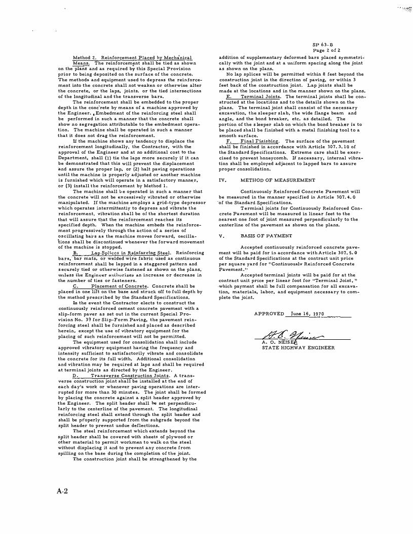
SPECIAL PROVI SION NO. 39-C SLIP-FORM PAVING
This Special Provision shall be applicable when indicated on the plans or in the proposal; and supersedes any conflicting requirements of the Department ' s Standard Specifications for Road and Bridge Construction. section and Article references herein are to the Standard Specifications .'
I . GENERAL
Except as otherwise provided herein, cement concrete pavements or bases shall be constructed in accordance with the Standard Specifications, plans, and standard Drawings . The pavements or bases may be constructed with the use of approved slip- form pavers and approved complementary spreading and finishing equipment in lieu of the spreading, consolidating and finishing equipment specified in Section 307, except that "Belting" and "Final Finish with Burlap Drag" shall be required.
II. MATERIALS
The load-transfer assemblies shall be modified at the ends to allow for approximately 4 inches of clearance between the assemblies and the slip-forms by welding the outer leg of the chair at an angle o f approximately 90 degrees with the upper and lower spacer bars.
The maximum slump of the concrete shall be 1� inches, with a plus � inch tolerance being allowed.
I I I . CONSTRUCTION METHODS
A . Subgrade and Aggregate Base Cpyrse . The subgrade and aggregate base course shall be constructed in accordance with all applicable requirements of Article 307 . 3 . 5, and a fine grading machine shall be required to prepare the proper grade for the paving equipment to the accuracy necessary to ensure that the finished concrete pavement or base will be in conformity with the tolerances set forth in the Standard Specification s .
If any traffic i s allowed to use the prepared aggregate base course, the course shall be rechecked and corrected prior to placing the concrete .
B . Pave r . The slip-form paver shall be an approved self-propelled type designed to spread, consolidate, and finish the concrete, in one complete pass o f the paver, in such a manner that a minimum of hand finishing will be necessary. The paver shall consolidate the concrete in a manner so as to not damage or displace the load-transfer devices and the steel reinforcement, and shall finish the concrete so as to produce a smooth, uniformly textured surface with the specified crown and slope ready for the final finishing .
c . Paving. The Contractor shall not operate a mixing plant inside the area to be traversed by the slip-form paver . The concrete shall be held to a uniform consistency so that unacceptable slumping
will not occur at the edge of the pavement. The paver shall be operated with as nearly a continuous forward movement as possible, and, when forward movement is stopped, the consolidating devices of the paver shall be stopped immediately.
If the concrete is placed in two operations, the width of the first placement may be reduced a maximum of 3 inches on each side.
Methods approved by the Engineer shall be used to construct longitudinal construction joints in accordance with the Standard Specifications, plans, Standard Drawings, and as specified herein. Fixed forms shall be used to prevent A!lY slump from occurring where the edge is to be abutted by subsequent pavement. The fixed forms shall be of adequate length, depth , and thickness to protect and maintain the pavement edge in correct alignment and depth , and shall be staked firmly in place with metal stakes . Where the edge is not to be abutted by subsequent pavement, edge slump not in excess of � inch will be permitted. Straightedge tolerances as required in Article 307 . 3 . 1 2 shall apply to that portion of the pavement bounded by lines 6 inches from the edges of the pavement. Edge slump will be measured with a 10-foot straightedge laid on the pavement perpendicular to the edge.
The Contractor shall utilize proper and adequate methods to prevent unacceptable slumping and to correct unavoidable slumping of the pavement edges due to all causes, in a manner approved by the Engineer, and shall have available at all times, the necessary mater ials, equipment, and labor to provide immediate protection of the edges and surface of the unhardened concrete against adverse weather conditions .
When concrete is being placed adjacent to an existing pavement, that part of the equipment which is supported on the existing pavement shall be equipped, or supplemented with approved protective materials, so as to not damage the surface of the pavement and shall be positioned at a sufficient distance from the edge of the existing
pavement to avoid damaging the edge .
STATE HIGHWAY ENGINEER
A-3
! . !! � i!� ��::·� ��� �·� T ��"' ' . �.·�� ... .... l; ��� � � " ""
A-4
% 0 t � ., ,__ ;!; 0 -,
� g � � "' J � u ;;: l=
;!: " ., .. z � J � .. , !;; " 0 � IX 0 ,_ J ;; I; 0
I] � u li �� " % II.I � Z IIl U0ii � "' - � 2 � � � z � (I) ll ij CO j d.l a:ctg lii � R � 5 � 1- Z t; z o Q U
0
·' ' � � - < � t H :.i l s � - '
� 1- - jJ ·� i--- n -' Ill! " u 'r -
"Ht
1' \l-�-'
li L •
'
� ' �
� J � 0 .. < J 0 li
l
� "'
DH ... IL FOR. ONE- M.LT PE-R LAN& WIDTH
� � �*" .... b, � ' l ' � � �
DE-TAIL FOR TWO MATS PE-R LA.,E WIDTH m�i.,<P-� :'.;?� T .., .. �r li l I I I f . I .---. ,..--,
PL;t,).l
w;,-c Ti•� �r-·n·'wtr: �J1�i':.:::j A •J"!/l -�1 ShU P..,ilrPn JJ•-fY."M•�tpE.><I'-'p-if!.m
PRDPIL"'"
E-ND LAP 0£:T.h.!L
t3,;;rs
LOOSE- 5AR CONSTRUCTION No"k. &r.s .s""'H be Sfu:l n:::qviremenf.s p_
er J;:mJ!; wictth ' 30No.5 Nrs� f!:'!..�din s;mi p!.m�, _ lf.Ul/ Sl(./n. « AJ:pro.<.. C:qo 7- of" IM <:nd01n01 o/<1 Additi0n<JJWS /Jars«!
;;�r;,;}'!£/'!r-J'I,f!;�;:;w .-,•x 1z -o-s� - f//be'P,{!,��'pt� ;,;rs l _r,;:•·'"� �'='""".'""I»� I (I l'l- 1'-nd of Diiigs 8'M.' i '" "'"" I P=: r-:"";1 L '",_,.-:·'"4 g:, , ,. " , I (\
�,_ ... ,. '.6�r"""'P""' "'""�n ... u�,-"i'�!""" L"t-
PRol'-t�� END L.AP DE-TAIL.
� N o-re-s�
TR.,A,.NSVERS& CONSTRUCTION JOINT USING DE-fORME-D BARS Non-:
Whcr" l�proJ"cf tcrminaf..s with ,; free end,.< fr.m.m:rs� c.on.!ilrvcfkmJoin.f .sh,;l/ba c.on#rvt:f�cf as .shoWTI ,;boY� f<>r fuf�.Jr& .;addrcnal r;:on.!ilrucfion.
of !:."'fJ!P fo trJ,�r .. >n""
DE-TAIL FOR ONE- MAT P&R LANE: WIDTH (])The Conlr.t�dor .sh;:J/Juse fhe doub/1'! l01p �qoir=>t:nlof the lonqii<Jdff>al .sled .Jt the
J't:'?J:'�'/!:;jy�'; 1�r -;';1:;sc
,.
Of:T,t.,JL FOR TWO MATS PER LANE- WIDTH
_,,..,_.
PLM"'
-i!"lf" Wr.eE-Ti».!i 7
PR_Of'IL�
END LAP DE-TAIL
':i:r.s/;,��f::.:, ��e�::,�m.:.J;o;jg;'�""�.��-.>1 fwo limes the spacing of lht: kmgiludm.;i/ steel .-f the first 18"/app;;sf the comlrocfion Jf'o�ht1tn:1t1:%::ti,%:;:/:,"':��.s;';kre;J ���d ;oinl. ®When !he norm"! �cnf width exc:uds u;
uct:Pf ilf r,;mps, ., iong(fudin<11 SiJWI:d consfJVCfion Join! sh;J/1� consfror:l?-d in 01c=rdom� wdh SfiJ11di>rd Drw9. RP5-0IO Currcnfedi!ion.
Longifudir!-•/--4 5i!W,d Jomf
TiC B;ir
TYPICAL $AWED JOINT SECTION
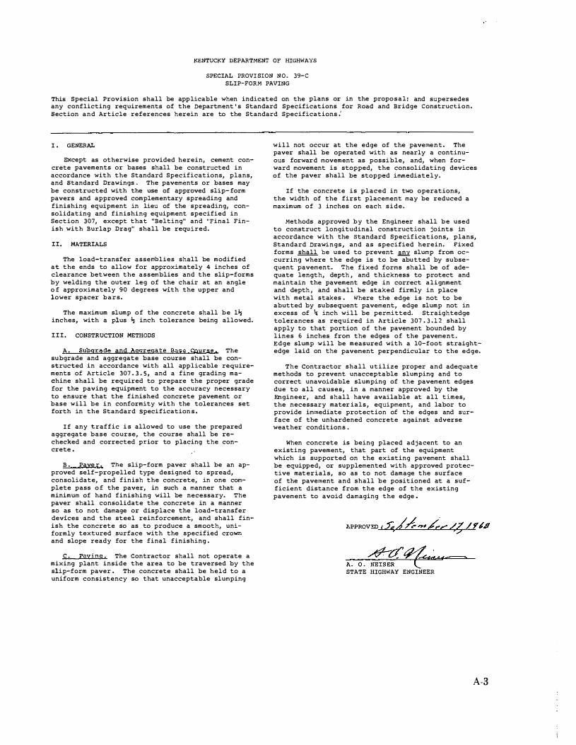
KENTUCKY BUREAU OF HIGHWAY5
STEE-L REINFORCE-ME-NT FOR td' 11-IICK
CONTINUOUSLY REINFORCED CONCRE-T£:- PAVE-ME-NT
-l
A-6
l 1
li
l
fl. � a: 1-i( "'
� -.1
�- C:ont.lhinf. Con<>-�+ 1�5' Min. O.ol. I<> st��eh>�c --G) 't-.. �h:ltlon �:r.:'f"'�}:,;g' �f.c
d
A
Po�oment Edg�· Tc,..,.,in<>l Jt End CcVI!r{SuOel-<lll) ! I I A
l' J 1!/'.'�-�·-··
_ __l : _ _,
-- ---L •'l "'" .. .,..,,.;,.,.:�;.,.,, I �;;·�"lMBt��.s -- -: ��·;;;��f (I piece - - -� ;!":f":t.�!!:�� �ro -- -i
;-- -; I __ ----+ I _ _ ---! 1---_l''
.,._ _ _ _ _ ' ' :----
+===== +-----
.,-----'
..__ _ _ _ _ ; - ----
�==== �I t E ..... c;;;. .. ;::.=..r-�-;---�--o· -� �. ���� 10'·0
HALF PLAN VIEW OF T ERMINAL .JOINT
( Nor To SeAL�)
<
� l '
DETAIL "O"AN
F l'l.co· I av:,�:-o. ·�·-o·3 - ·�o�':l" *•''''�-
@(� � ( (��.��f �i.ifh) CURVE
TERMINAL .IOI�C.ROSS tsto;E; c;·
O<'M.';:
""� Limifo of Co!'linu•n.ool� l'l•inf<>ro....O Cano.r&lo. Roo&rn<t-�nl ltS•-o- M•"immn Dool""""' lo Str""t'-'n • C..nv,.nlicn<:tl J0o_ii��·,=·�e�oo�o,�o�Co=•=·=··=-=c•=·=·=·=·=·=•m=•o=·==
C.R.C- ...,v .. m&n\ Thic..kn"'"" _ P<14 Umito of c;,..,v,.nhonal .Joint .. d F\c.mfcr.: ... d Con';!"elo. Po ....,.n-,enl � r-s .... O..l<>il ·,o.,- Conv�Mianal Pa�rn�nl "Tlucl!��� .... ,,r.,,-,_,"" "''""' wk .. M•nh
ct-o.,;r I� WF .5a Pov.:mer* To s;uclure F,<;ii. ' :j
5upp<>�t l J �/ -""•• � "aro'e e•c.-c. Convenf-ioMtl L- (l'l,U Sor� tquanY 5P�.:td(l'q" Lim•)
Povtmenf- Thicb>t�� ------ to•-o• 51 .... ��:b Sl<>b .. '---------1 SECTION A � A
TERMINAL .JOINT
(lloT To 5c..,_t)
C.�.C- Pavement T!uelcn•55 '-- -�:��;;.��· .. Joint�
Non ' The COf)fr<Jcl IJnit prict: ;fer lin- ff. .Jhal! mc!ude all labor, r:,;��'ii%t7/',111n'�ft:;zgc;e;,ff,�/ih 'J: .. �;,g.p/ete:
GENERAL NOTES
(i) GaiV<Ini;o:& <1flcr '""''"'"'"''""·
® �:�:dboo�t:a.r·s";.,;i:· ":�:,'\,· .. ,.. �t�'h.':"�." and ota<;�gcrcd "" ho>r�on'lat lo.9 ":f- c.hannc.l .
@J!!oolt<..,., of tor flang• on Con\_ Ro<inf C<>r>"· """'' ��; ... ::� 1/'C-��� ...._ p<>or•ted will\ Cull><>"-k
® D���- :'.:'!,/"t.�":C..� .. !::. tt" �\!: ��a.:����d s:r:l
bq.amJ
@ 5C:nv��t .. �· �i���°C;-�;.'"p.�:._tdj!\;.t· J:t<>ilo .
@ En�o of VF·I!o&<>«> on� St.,el .O.n<;�l" •"a \I ..._ Mi1&r c. .. t I• <.onfar"' with th& vo.rtic.al foo.& .. r th.,_ �'"""'""' .. "� o..t'lc.
(2/p�'f"
�._;;:::�.,;'h.':.:.i'n:Pf�'!\�n.'E �h•tiao .,,.. olntio>no
@ p�;o>r Ia 9alvnn;�;.,�, tho. �-&._.,.., ""d Slo<c.l -""�'"' .,ho!l »c. fa»r•o..,lo.d to ren .. .,.t the. �::..]::.', ��v:.m:�� ... �:: ����;.:.,:• ,t'\'h:� �po.c.ofio.d t&nnon"l l""'t olnl•on fnll• w\th<n '"" l;m;to of tho. ,.,.,,. • .,, '"""-af1" or th& tnn,.<-nl run-e .. t of o <:Ut"YO. .
T- '"'"'"'h• of .,.....,.._.,..,� ond sr ... l """''" "'"\! b< ue&d ... <th a ..,,.ldo.d JOint at �•• Ap<;.<. 5nop ?h:"'�;�� "lf"'�,!:" ,':_':,�'t��"''!..-�"r,.� . .-.,�al .".r
for cr-own at opt;< O<< .51d. Dr"'9- II.PS-010 curren!-tdolicn
o;,_·, �)I;·
J""id._ fac.o. <>f E:n� Co>v.or ���c.t"';.::�� .. i't''�c.-z5o
- II" C.RC. Pa.Jcmtn!-- .,. c.�.c. Pa->nmtnt )CAL� , /�>
END COVER
KENTUCKY BUREAU OF HIGHWAYS
CONTINUOUSLY REINFORCE-D
CoNCRETE PAVEMENT
TERMINAL JOINT DETAIL&
-'ltflu--'hi'--
:: -