Embed Size (px)
Citation preview
Crispin Multiplex Manufacturing Co. • 600 Fowler Avenue • Berwick, PA 18603 • 1-800-247-VALVT: (570) 752-4524 • F: (570) 752-4962 • www.crispinvalve.com • [email protected]
Sizes from 3” to 72” • #125 and #250 ratings available• 55º seating angle • 40% size increase through seat
The TD SeriesTilting Disc Check Valve
CrispinSince 1905
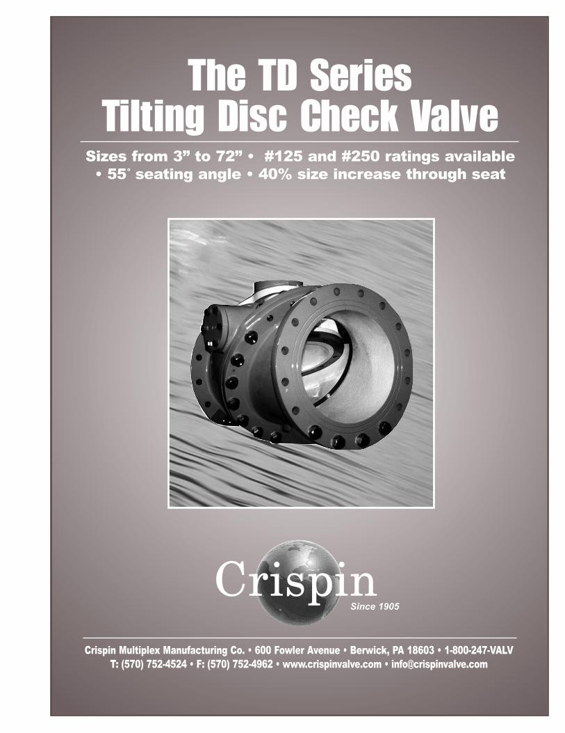
TD Series Tilting Disc CheckValves are available in sizesfrom 3” to 72”.They are available
with top- or bottom-mounted buffering sys -tems, as well as a varietyof in dustry preferred mate-rial op tions, in cluding aduc tile iron body and alu-minum bronze seating.
Tilting Disc Series valvesalso offer fixed pivot points, anexternal position indicator on sizes10" and larger, and a 40% increase in
nominal valve size through the seatarea. Seating is achiev ed at a 55
degree angle, with fullopening re quiring theseat to travel no morethan 40 degrees fromthe seating position.The Crispin Tilting
Disc is contoured to pre-vent fluttering above a 4feet per second velocity. Inaddition, the body seat is
also de signed so that it may bereplaced in the field without
requiring any special tools. �
T he hallmark of the our TDSeries is its superior designand function, which pro-
vides the most efficient ap proachto flow reversal, and offers a headloss lower than that of most anyother check valve made.
Its 55 degree slanted seatposition, unique to the TD Series,provides ex tremely high efficien-cy and operability.
Seating The Tilting Disc Valve
accom plishes full flow open ingby having the disc pivot or “tilt”in the flow of the media. Swingcheck valves move the disc outof the flow by displacing the seatdisc to the upper portion of thevalve. By pivoting the disc in theflow, the opening stroke range ofthe TD Series is far less than thatof other valves, reducing theopening and closing times criti-
cal to controlling flow reversaland reducing water hammer.
The seating surfaces of theseat ring and disc are machinedto an angle of approximately 20degrees, providing more clear-ance right up to closing, whilereducing seat wear and im -proving sealing properties.
Opening StrokeThe key to the Tilting Disc
Valve’s efficiency is its “in theflow pivot.” When the velocityis sufficient to open the valve,the pivot pin clearance allowsthe valve to un-seat withoutsticking. Once open, the tear-drop like de sign of the disc keepsit stable and un-fluttering in theflow. Meanwhile, full opening isachiev ed through only 40%stroke from the seated position.
� Disc PivotingThe seat disc opens and
closes the valve by pivoting ontwo fixed pivot shafts attach edto the disc from either side ofthe body. Re placeable pivotbushings of a different materialhardness in the disc are theactual pivot points, and arelocated almost 1/3 of the waydown the disc, leaving 2/3 ofthe disc weight below. Theresulting counter balance effectcloses the valve quickly, yetlimits slamming.
� Pivot Pin ClearanceSince the “tilting” of the
disc on a 1/3, 2/3 split puts partof the disc through the seatingarea, there must be a smallclearance around the pivotbushing and pivot shaft. Thetop of the disc seats from theopposite direction as the bot-tom. This built in clearanceallows the disc to “float” intoplace at final seating. �
TD SER
IES
Tilting Disc Check Valve
Tilting Disc Check Valve
Crispin Valve, 600 Fowler Ave., Berwick, PA 18603 • 1-800-247-VALV • T: (570) 752-4524 • F: (570) 752-4962 • WWW.CRISPINVALVE.COM • [email protected]
By pivoting the disc in the flow, the opening stroke range of the Tilting Disc Valve is muchless than that of other check valves, reducing the opening and closing times critical tocontrolling flow reversal and reducing water hammer. In addition, the unique 55 degreeslanted seat position of the TD Series ensures extremely high efficiency and operability.
2
Tilting Disc Check ValveTD
SERIES
Crispin Valve, 600 Fowler Ave., Berwick, PA 18603 • 1-800-247-VALV • T: (570) 752-4524 • F: (570) 752-4962 • WWW.CRISPINVALVE.COM • [email protected] TD
3
� Longer Laying LengthHaving the disc “tilt” in the
media gives the valve a longerlaying length or face-to-facedimension than other checkvalves. This extended lengthprovides a very smooth bodyand disc contour, thus reducingthe turbulence common to otherde signs.
� Increased Flow AreaWith a flow area that is at
least 40% greater than the nomi-nal valve size, the Tilting DiscCheck Valve has a much lowerhead loss than a con ven tionalswing check valve. It has threetimes higher flow in many cases.
� Field Replaceable SeatThe Crispin Multiplex TD
Series Tilting Disc Check Valveis manufactured with ease offield maintenance in mind. Thebody seat is replaceable in thefield without the need for spe-cial tools or equipment, thusreducing valve down time.
� External Position IndicatorDirectly attached to the disc
itself through one pivot shaft,this indicator serves as an easyand positive reference for deter-mining whether the valve isopen or closed. This is standardon valves 10" and larger.
� Dual Inspection PortsAn inspection port is located
on the top and bottom side of theseat for examination of normalwear. It also serves as the mount-ing point for optional dashpots.
� By-Pass PipingOptional by-pass piping is
available for special needs,including slow line filling andcontrolled line drain.
� DashpotsDesign ed to control the
open ing and closing speeds ofthe valve, optional dashpotshelp eliminate line surges andvalve wear. Available with topand bottom mountings, they arefield adjustable and can often beadded later. Both uti lize a highquality hy draulic piston cylinderto control disc movement.
Bottom Side DashpotThis dashpot features a
rounded end shaft that pro jectsthrough the 55 degree angledseat ring. It is not physically
attached to the disc itself. Ittherefore cannot control the rateat which the valve opens, butrather controls the last 10% ofthe closing stroke.
Upon closure, the disc strikesthe rounded end rod connected tothe piston in the hydraulic cylin-der. Oil in the cylinder is dis-placed into the accumulatingtank. The rate of this oil displace-ment is the rate at which thevalve closes during that last 10%of movement, and it is adjustablethrough the use of a needle valve.After closure, when the valve re -opens, a spring pushes the rod
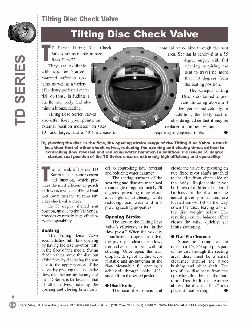
ITEM DESCRIPTION MATERIAL ASTM1 Outlet Body Cast Iron A126 Class B 2 Inlet Body Cast Iron A126 Class B 3 Body Seat Ring Alum. Bronze B271-954 4 O-Ring Buna N A5656A 5 Tilting Disc Ductile Iron A536 Gr 65-45-12 6 Disc Ring Alum. Bronze B271-955 7 O-Ring Buna N AS 568A 8 Disc Bushing Stainless Steel AISI Type 304 9 Bushing/Drive Pl. Stainless Steel Stainless Steel 10 Pivot Pin 17-4 PH A564-630-H1025 11 Inspection Cover Cast Iron A126 Class B 12 Hex Head Bolt Carbon Steel A307 Gr. B 13 Inspection Cover A126 Class B A126 Class B 14 Hex Head Bolt Carbon Steel A307 Gr. B 15 End Bearing Cap Cast Iron A126 Class B
Tilting Disc Check Valve
26
18
2716
1017
9
2928
191524
17
10
8
25
29 28
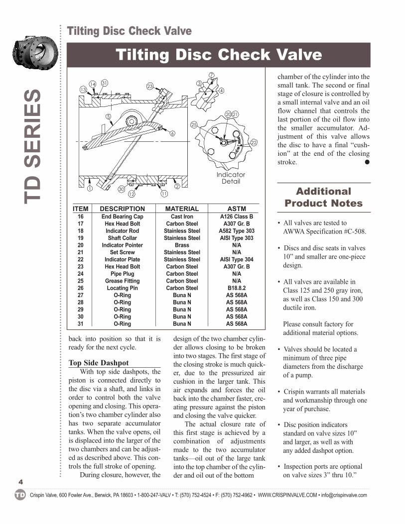
back into position so that it isready for the next cycle.
Top Side DashpotWith top side dashpots, the
piston is connected directly tothe disc via a shaft, and links inorder to control both the valveopening and closing. This opera-tion’s two chamber cylinder alsohas two separate accumulatortanks. When the valve opens, oilis displaced into the larger of thetwo chambers and can be adjust-ed as described above. This con-trols the full stroke of opening.
During closure, however, the
design of the two chamber cylin-der allows closing to be brokeninto two stages. The first stage ofthe closing stroke is much quick-er, due to the pressurized aircushion in the larger tank. Thisair expands and forces the oilback into the chamber faster, cre-ating pressure against the pistonand closing the valve quicker.
The actual closure rate ofthis first stage is achieved by acombination of adjustmentsmade to the two accumulatortanks—oil out of the large tankinto the top chamber of the cylin-der and oil out of the bottom
chamber of the cylinder into thesmall tank. The second or finalstage of closure is controlled bya small internal valve and an oilflow channel that controls thelast portion of the oil flow intothe smaller accumulator. Ad -justment of this valve allowsthe disc to have a final “cush-ion” at the end of the closingstroke. �
Additional Product Notes
• All valves are tested toAWWA Specification #C-508.
• Discs and disc seats in valves10” and smaller are one-piecedesign.
• All valves are available inClass 125 and 250 gray iron,as well as Class 150 and 300ductile iron.
Please consult factory for additional material options.
• Valves should be located aminimum of three pipe diameters from the dischargeof a pump.
• Crispin warrants all materialsand workmanship through oneyear of purchase.
• Disc position indicators standard on valve sizes 10” and larger, as well as with any added dashpot option.
• Inspection ports are optionalon valve sizes 3” thru 10.”
ITEM DESCRIPTION MATERIAL ASTM16 End Bearing Cap Cast Iron A126 Class B 17 Hex Head Bolt Carbon Steel A307 Gr. B 18 Indicator Rod Stainless Steel A582 Type 303 19 Shaft Collar Stainless Steel AISI Type 303 20 Indicator Pointer Brass N/A 21 Set Screw Stainless Steel N/A 22 Indicator Plate Stainless Steel AISI Type 304 23 Hex Head Bolt Carbon Steel A307 Gr. B 24 Pipe Plug Carbon Steel N/A 25 Grease Fitting Carbon Steel N/A 26 Locating Pin Carbon Steel B18.8.2 27 O-Ring Buna N AS 568A 28 O-Ring Buna N AS 568A 29 O-Ring Buna N AS 568A 30 O-Ring Buna N AS 568A 31 O-Ring Buna N AS 568A
TD SER
IES
Tilting Disc Check Valve
Tilting Disc Check Valve
Crispin Valve, 600 Fowler Ave., Berwick, PA 18603 • 1-800-247-VALV • T: (570) 752-4524 • F: (570) 752-4962 • WWW.CRISPINVALVE.COM • [email protected]
4
121
5
13
2
14 31
6
23
3011
34
7
20 21
IndicatorDetail
22
25
Tilting Disc Check ValveTD
SERIES
Crispin Valve, 600 Fowler Ave., Berwick, PA 18603 • 1-800-247-VALV • T: (570) 752-4524 • F: (570) 752-4962 • WWW.CRISPINVALVE.COM • [email protected] TD
5
Tilting Disc Check Valve
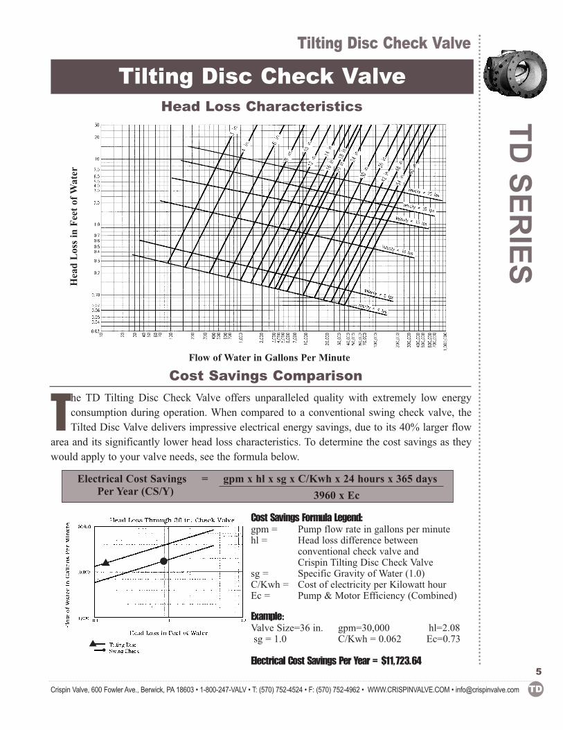
Electrical Cost Savings = gpm x hl x sg x C/Kwh x 24 hours x 365 days3960 x Ec
Head Loss Characteristics
Cost Savings ComparisonFlow of Water in Gallons Per Minute
Cost Savings Formula Legend: gpm = Pump flow rate in gallons per minutehl = Head loss difference between
conventional check valve and Crispin Tilting Disc Check Valve
sg = Specific Gravity of Water (1.0)C/Kwh = Cost of electricity per Kilowatt hourEc = Pump & Motor Efficiency (Combined)
Example:Valve Size=36 in. gpm=30,000 hl=2.08 sg = 1.0 C/Kwh = 0.062 Ec=0.73
Electrical Cost Savings Per Year = $11,723.64
The TD Tilting Disc Check Valve offers unparalleled quality with extremely low energy consumption during operation. When compared to a conventional swing check valve, theTilted Disc Valve delivers impressive electrical energy savings, due to its 40% larger flow
area and its significantly lower head loss characteristics. To determine the cost savings as theywould apply to your valve needs, see the formula below.
� �
Head Loss in Fe
et of W
ater
Per Year (CS/Y)
� •
DIMEN
SION SHEE
T FO
R TD SER
IES
Dimension Sheet for TD Series
Tilting Disc Check Valve
346810121416182024303642485460
VALVESize
Crispin Valve, 600 Fowler Ave., Berwick, PA 18603 • 1-800-247-VALV • T: (570) 752-4524 • F: (570) 752-4962 • WWW.CRISPINVALVE.COM • [email protected]
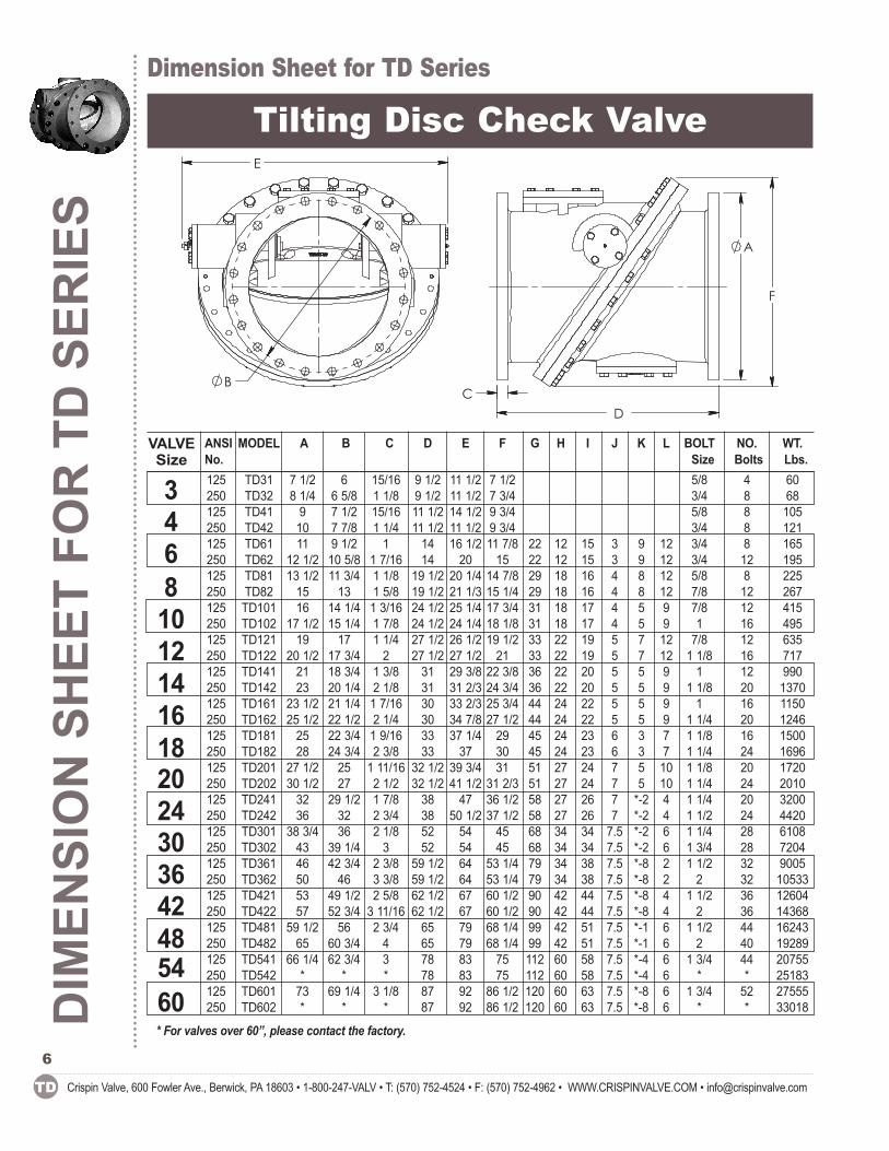
ANSI MODEL A B C D E F G H I J K L BOLT NO. WT.No. Size Bolts Lbs.125 TD31 7 1/2 6 15/16 9 1/2 11 1/2 7 1/2 5/8 4 60250 TD32 8 1/4 6 5/8 1 1/8 9 1/2 11 1/2 7 3/4 3/4 8 68125 TD41 9 7 1/2 15/16 11 1/2 14 1/2 9 3/4 5/8 8 105250 TD42 10 7 7/8 1 1/4 11 1/2 11 1/2 9 3/4 3/4 8 121125 TD61 11 9 1/2 1 14 16 1/2 11 7/8 22 12 15 3 9 12 3/4 8 165250 TD62 12 1/2 10 5/8 1 7/16 14 20 15 22 12 15 3 9 12 3/4 12 195125 TD81 13 1/2 11 3/4 1 1/8 19 1/2 20 1/4 14 7/8 29 18 16 4 8 12 5/8 8 225250 TD82 15 13 1 5/8 19 1/2 21 1/3 15 1/4 29 18 16 4 8 12 7/8 12 267125 TD101 16 14 1/4 1 3/16 24 1/2 25 1/4 17 3/4 31 18 17 4 5 9 7/8 12 415250 TD102 17 1/2 15 1/4 1 7/8 24 1/2 24 1/4 18 1/8 31 18 17 4 5 9 1 16 495125 TD121 19 17 1 1/4 27 1/2 26 1/2 19 1/2 33 22 19 5 7 12 7/8 12 635250 TD122 20 1/2 17 3/4 2 27 1/2 27 1/2 21 33 22 19 5 7 12 1 1/8 16 717125 TD141 21 18 3/4 1 3/8 31 29 3/8 22 3/8 36 22 20 5 5 9 1 12 990250 TD142 23 20 1/4 2 1/8 31 31 2/3 24 3/4 36 22 20 5 5 9 1 1/8 20 1370125 TD161 23 1/2 21 1/4 1 7/16 30 33 2/3 25 3/4 44 24 22 5 5 9 1 16 1150250 TD162 25 1/2 22 1/2 2 1/4 30 34 7/8 27 1/2 44 24 22 5 5 9 1 1/4 20 1246125 TD181 25 22 3/4 1 9/16 33 37 1/4 29 45 24 23 6 3 7 1 1/8 16 1500250 TD182 28 24 3/4 2 3/8 33 37 30 45 24 23 6 3 7 1 1/4 24 1696125 TD201 27 1/2 25 1 11/16 32 1/2 39 3/4 31 51 27 24 7 5 10 1 1/8 20 1720250 TD202 30 1/2 27 2 1/2 32 1/2 41 1/2 31 2/3 51 27 24 7 5 10 1 1/4 24 2010125 TD241 32 29 1/2 1 7/8 38 47 36 1/2 58 27 26 7 *-2 4 1 1/4 20 3200250 TD242 36 32 2 3/4 38 50 1/2 37 1/2 58 27 26 7 *-2 4 1 1/2 24 4420125 TD301 38 3/4 36 2 1/8 52 54 45 68 34 34 7.5 *-2 6 1 1/4 28 6108250 TD302 43 39 1/4 3 52 54 45 68 34 34 7.5 *-2 6 1 3/4 28 7204125 TD361 46 42 3/4 2 3/8 59 1/2 64 53 1/4 79 34 38 7.5 *-8 2 1 1/2 32 9005250 TD362 50 46 3 3/8 59 1/2 64 53 1/4 79 34 38 7.5 *-8 2 2 32 10533125 TD421 53 49 1/2 2 5/8 62 1/2 67 60 1/2 90 42 44 7.5 *-8 4 1 1/2 36 12604250 TD422 57 52 3/4 3 11/16 62 1/2 67 60 1/2 90 42 44 7.5 *-8 4 2 36 14368125 TD481 59 1/2 56 2 3/4 65 79 68 1/4 99 42 51 7.5 *-1 6 1 1/2 44 16243250 TD482 65 60 3/4 4 65 79 68 1/4 99 42 51 7.5 *-1 6 2 40 19289125 TD541 66 1/4 62 3/4 3 78 83 75 112 60 58 7.5 *-4 6 1 3/4 44 20755250 TD542 * * * 78 83 75 112 60 58 7.5 *-4 6 * * 25183125 TD601 73 69 1/4 3 1/8 87 92 86 1/2 120 60 63 7.5 *-8 6 1 3/4 52 27555250 TD602 * * * 87 92 86 1/2 120 60 63 7.5 *-8 6 * * 33018
6
* For valves over 60”, please contact the factory.
B
E
F
D C
A
Submittal Sheet for Crispin TD SeriesSU
BMITTA
L SHEET FO
R TD
SERIES
Crispin Valve, 600 Fowler Ave., Berwick, PA 18603 • 1-800-247-VALV • T: (570) 752-4524 • F: (570) 752-4962 • WWW.CRISPINVALVE.COM • [email protected] TD
7
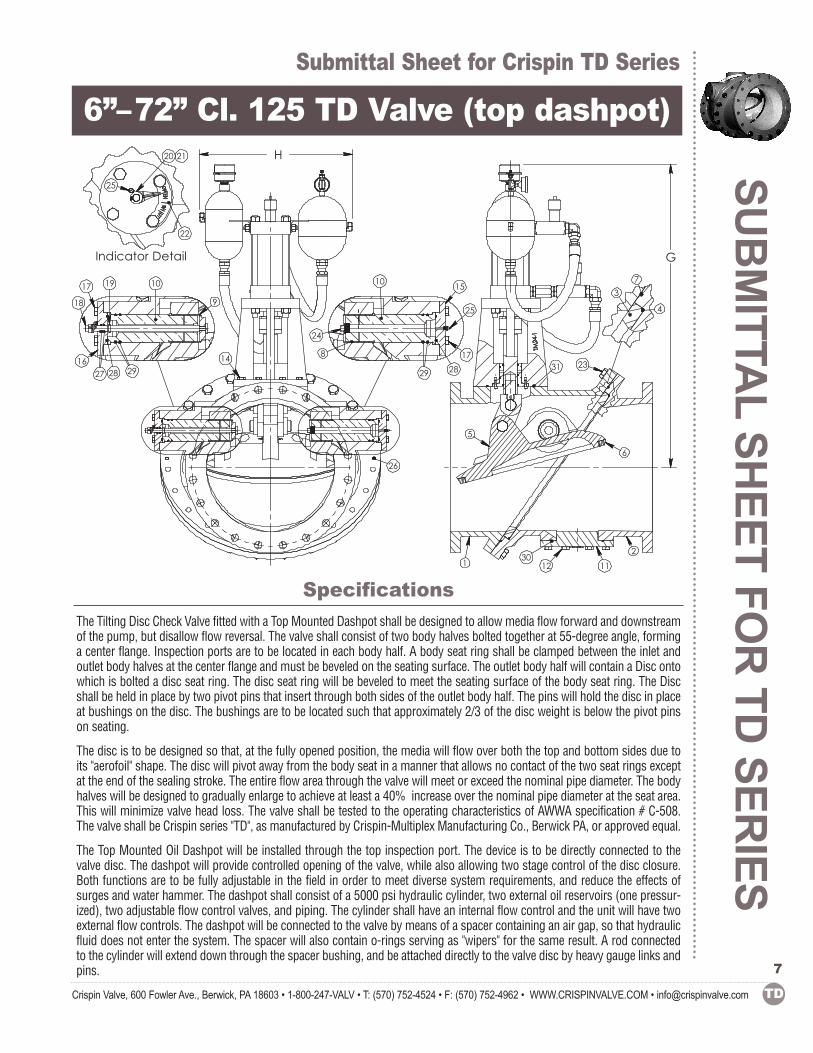
6”–72” Cl. 125 TD Valve (top dashpot)
Specifications
The Tilting Disc Check Valve fitted with a Top Mounted Dashpot shall be designed to allow media flow forward and downstreamof the pump, but disallow flow reversal. The valve shall consist of two body halves bolted together at 55-degree angle, forminga center flange. Inspection ports are to be located in each body half. A body seat ring shall be clamped between the inlet andoutlet body halves at the center flange and must be beveled on the seating surface. The outlet body half will contain a Disc ontowhich is bolted a disc seat ring. The disc seat ring will be beveled to meet the seating surface of the body seat ring. The Discshall be held in place by two pivot pins that insert through both sides of the outlet body half. The pins will hold the disc in placeat bushings on the disc. The bushings are to be located such that approximately 2/3 of the disc weight is below the pivot pinson seating.
The disc is to be designed so that, at the fully opened position, the media will flow over both the top and bottom sides due toits "aerofoil" shape. The disc will pivot away from the body seat in a manner that allows no contact of the two seat rings exceptat the end of the sealing stroke. The entire flow area through the valve will meet or exceed the nominal pipe diameter. The bodyhalves will be designed to gradually enlarge to achieve at least a 40% increase over the nominal pipe diameter at the seat area.This will minimize valve head loss. The valve shall be tested to the operating characteristics of AWWA specification # C-508.The valve shall be Crispin series "TD", as manufactured by Crispin-Multiplex Manufacturing Co., Berwick PA, or approved equal.
The Top Mounted Oil Dashpot will be installed through the top inspection port. The device is to be directly connected to thevalve disc. The dashpot will provide controlled opening of the valve, while also allowing two stage control of the disc closure.Both functions are to be fully adjustable in the field in order to meet diverse system requirements, and reduce the effects ofsurges and water hammer. The dashpot shall consist of a 5000 psi hydraulic cylinder, two external oil reservoirs (one pressur-ized), two adjustable flow control valves, and piping. The cylinder shall have an internal flow control and the unit will have twoexternal flow controls. The dashpot will be connected to the valve by means of a spacer containing an air gap, so that hydraulicfluid does not enter the system. The spacer will also contain o-rings serving as "wipers" for the same result. A rod connectedto the cylinder will extend down through the spacer bushing, and be attached directly to the valve disc by heavy gauge links andpins.
5
31
1212
6
23
3011
G
14
26
H
18
16
17
27
10
9
2928
19
17
25
24
8
1510
29 28
20 21
Indicator Detail
22
25
3
4
7
SUBMITTA
L SH
EET TD
SER
IES
Submittal Sheet for Crispin TD Series
Crispin Valve, 600 Fowler Ave., Berwick, PA 18603 • 1-800-247-VALV • T: (570) 752-4524 • F: (570) 752-4962 • WWW.CRISPINVALVE.COM • [email protected]
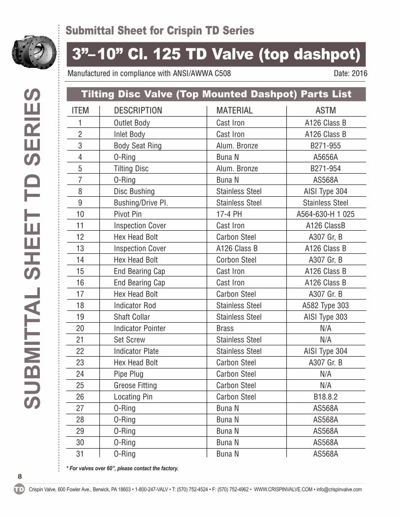
3”–10” Cl. 125 TD Valve (top dashpot)Manufactured in compliance with ANSI/AWWA C508 Date: 2016
ITEM DESCRIPTION MATERIAL ASTM1 Outlet Body Cast Iron A126 Class B 2 Inlet Body Cast Iron A126 Class B 3 Body Seat Ring Alum. Bronze B271-955 4 O-Ring Buna N A5656A 5 Tilting Disc Alum. Bronze B271-954 7 O-Ring Buna N AS568A 8 Disc Bushing Stainless Steel AISI Type 304 9 Bushing/Drive PI. Stainless Steel Stainless Steel 10 Pivot Pin 17-4 PH A564-630-H 1 025 11 Inspection Cover Cast Iron A126 ClassB 12 Hex Head Bolt Carbon Steel A307 Gr, B 13 Inspection Cover A126 Class B A126 Class B 14 Hex Head Bolt Corbon Steel A307 Gr, B 15 End Bearing Cap Cast Iron A126 Class B 16 End Bearing Cap Cast Iron A126 Class B 17 Hex Head Bolt Carbon Steel A307 Gr. B 18 Indicator Rod Stainless Steel A582 Type 303 19 Shaft Collar Stainless Steel AISI Type 303 20 Indicator Pointer Brass N/A 21 Set Screw Stainless Steel N/A 22 Indicator Plate Stainless Steel AISI Type 304 23 Hex Head Bolt Carbon Steel A307 Gr. B 24 Pipe Plug Carbon Steel N/A 25 Greose Fitting Carbon Steel N/A 26 Locating Pin Carbon Steel B18.8.2 27 O-Ring Buna N AS568A 28 O-Ring Buna N AS568A 29 O-Ring Buna N AS568A 30 O-Ring Buna N AS568A 31 O-Ring Buna N AS568A
Tilting Disc Valve (Top Mounted Dashpot) Parts List
8* For valves over 60”, please contact the factory.
Submittal Sheet for Crispin TD SeriesSU
BMITTA
L SHEET FO
R TD
SERIES
Crispin Valve, 600 Fowler Ave., Berwick, PA 18603 • 1-800-247-VALV • T: (570) 752-4524 • F: (570) 752-4962 • WWW.CRISPINVALVE.COM • [email protected] TD
9
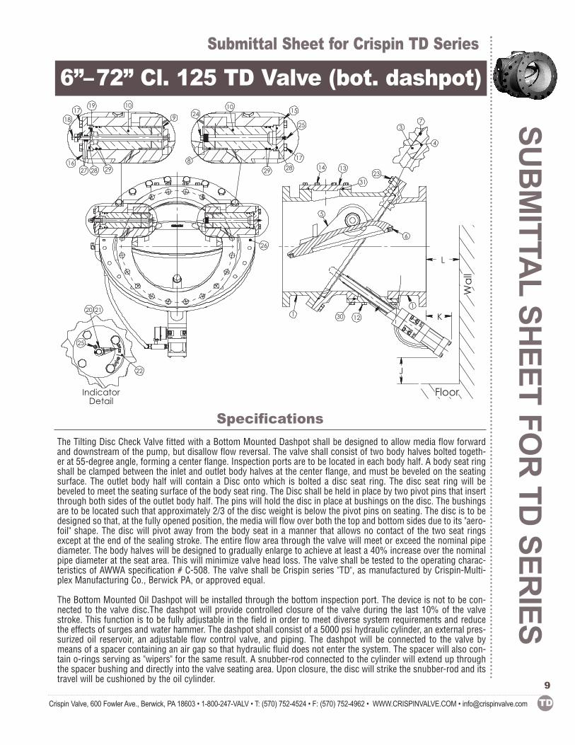
6”–72” Cl. 125 TD Valve (bot. dashpot)
Specifications
L
J
1
1230
Floor
6
Wall
1
5
1314
3123
K
26
18
16
17
27
10
9
2928
19
17
25
24
8
1510
29 28
20 21
IndicatorDetail
22
25
3
4
7
The Tilting Disc Check Valve fitted with a Bottom Mounted Dashpot shall be designed to allow media flow forwardand downstream of the pump, but disallow flow reversal. The valve shall consist of two body halves bolted togeth-er at 55-degree angle, forming a center flange. Inspection ports are to be located in each body half. A body seat ringshall be clamped between the inlet and outlet body halves at the center flange, and must be beveled on the seatingsurface. The outlet body half will contain a Disc onto which is bolted a disc seat ring. The disc seat ring will bebeveled to meet the seating surface of the body seat ring. The Disc shall be held in place by two pivot pins that insertthrough both sides of the outlet body half. The pins will hold the disc in place at bushings on the disc. The bushingsare to be located such that approximately 2/3 of the disc weight is below the pivot pins on seating. The disc is to bedesigned so that, at the fully opened position, the media will flow over both the top and bottom sides due to its "aero-foil" shape. The disc will pivot away from the body seat in a manner that allows no contact of the two seat ringsexcept at the end of the sealing stroke. The entire flow area through the valve will meet or exceed the nominal pipediameter. The body halves will be designed to gradually enlarge to achieve at least a 40% increase over the nominalpipe diameter at the seat area. This will minimize valve head loss. The valve shall be tested to the operating charac-teristics of AWWA specification # C-508. The valve shall be Crispin series "TD", as manufactured by Crispin-Multi-plex Manufacturing Co., Berwick PA, or approved equal.
The Bottom Mounted Oil Dashpot will be installed through the bottom inspection port. The device is not to be con-nected to the valve disc.The dashpot will provide controlled closure of the valve during the last 10% of the valvestroke. This function is to be fully adjustable in the field in order to meet diverse system requirements and reducethe effects of surges and water hammer. The dashpot shall consist of a 5000 psi hydraulic cylinder, an external pres-surized oil reservoir, an adjustable flow control valve, and piping. The dashpot will be connected to the valve bymeans of a spacer containing an air gap so that hydraulic fluid does not enter the system. The spacer will also con-tain o-rings serving as "wipers" for the same result. A snubber-rod connected to the cylinder will extend up throughthe spacer bushing and directly into the valve seating area. Upon closure, the disc will strike the snubber-rod and itstravel will be cushioned by the oil cylinder.
SUBMITTAL SH
EET FO
R TD SER
IES
Submittal Sheet for Crispin TD Series
Crispin Valve, 600 Fowler Ave., Berwick, PA 18603 • 1-800-247-VALV • T: (570) 752-4524 • F: (570) 752-4962 • WWW.CRISPINVALVE.COM • [email protected]
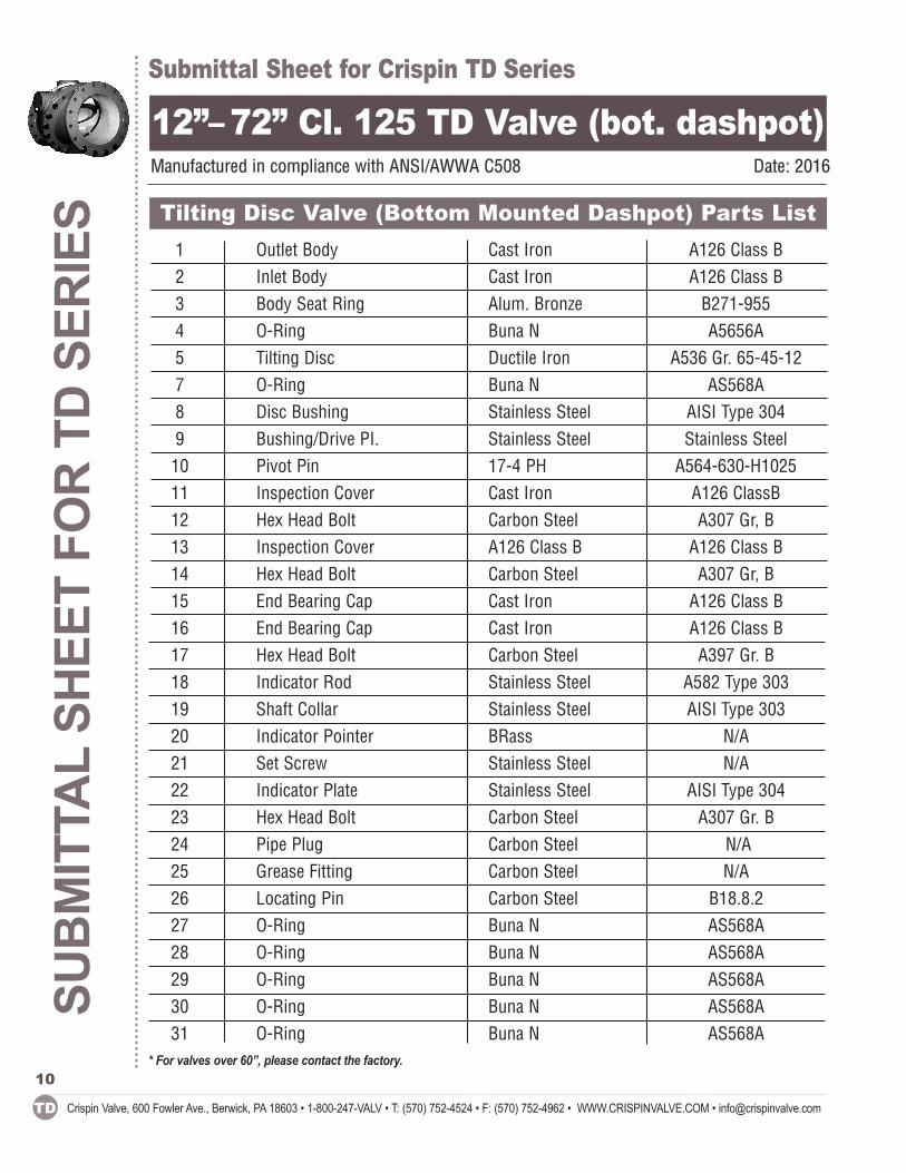
12”– 72” Cl. 125 TD Valve (bot. dashpot)Manufactured in compliance with ANSI/AWWA C508 Date: 2016
1 Outlet Body Cast Iron A126 Class B 2 Inlet Body Cast Iron A126 Class B 3 Body Seat Ring Alum. Bronze B271-955 4 O-Ring Buna N A5656A 5 Tilting Disc Ductile Iron A536 Gr. 65-45-127 O-Ring Buna N AS568A 8 Disc Bushing Stainless Steel AISI Type 304 9 Bushing/Drive PI. Stainless Steel Stainless Steel 10 Pivot Pin 17-4 PH A564-630-H1025 11 Inspection Cover Cast Iron A126 ClassB 12 Hex Head Bolt Carbon Steel A307 Gr, B 13 Inspection Cover A126 Class B A126 Class B 14 Hex Head Bolt Carbon Steel A307 Gr, B 15 End Bearing Cap Cast Iron A126 Class B16 End Bearing Cap Cast Iron A126 Class B17 Hex Head Bolt Carbon Steel A397 Gr. B18 Indicator Rod Stainless Steel A582 Type 30319 Shaft Collar Stainless Steel AISI Type 30320 Indicator Pointer BRass N/A21 Set Screw Stainless Steel N/A22 Indicator Plate Stainless Steel AISI Type 30423 Hex Head Bolt Carbon Steel A307 Gr. B24 Pipe Plug Carbon Steel N/A25 Grease Fitting Carbon Steel N/A26 Locating Pin Carbon Steel B18.8.227 O-Ring Buna N AS568A28 O-Ring Buna N AS568A29 O-Ring Buna N AS568A30 O-Ring Buna N AS568A31 O-Ring Buna N AS568A
Tilting Disc Valve (Bottom Mounted Dashpot) Parts List
10* For valves over 60”, please contact the factory.