Embed Size (px)
Citation preview
Bull. Mater. Sci., Vol. 5, No.2, June 1983, pp. 111-121.© Printed in India.
A tilting disc valve - component materials and hydraulic function
G S B H U V A N E S H W A R , A V R A M A N I and M S V A L I A T H A N * Departments of Biomedical Engineering and Cardiac Surgery*, Sree Chitra Tirunal In- stitute for Medical Sciences and Technology, Trivandrum 695 012, India.
MS received 31 December 1981
Abstract. The component materials used in fabrication of the Chitra heart valve, their choice and screening are described. Further the haemodynamic performance of this valve, which is under development and an equal sized No. 27 Bjork-Shiley valve prosthesis was compared in a left-heart pulse duplicator under similar conditions of flow rates and pressures. They were tested in both the aortic and mitral positions of the duplicator. Regurgitant volumes and transvalvular pressure gradients were measured over flow rates ranging from 2 to 8 LPM. Flow patterns of the fluid flow across the valves were also photographed. The results indicate that the performance of the indigenous valve is com- parable, if not marginally better, to that of the well-established Bjork-Shiley valve. Transvalvular gradients and regurgitant volumes were marginally lower for the Cbitra valve. This is attributed to the improved design of the valve disc shape.
Keywords. Heart valve; pulse duplicator; Bjork-Shiley valve; tilting disc valve.
1. I n t r o d u c t i o n
Even though Hufnagel and Harvey (1953) heralded the era of prosthetic heart valves by placing a caged-ball valve in the descending thoracic aorta, prosthetic valve replace. ment did not become a s tandard surgical practice until the introduction of caged- ball valves in the subcoronary position by Harken et al (1960). In subsequent years, other prosthetic valve models have emerged and continually yielded to newer designs such as caged disc, tri-leaflet, butterfly leaflet, double-caged ball, tilting disc etc. These developmental efforts have had as their p r imary aims the improvemen t of haemodynamics and enhancement of the blood compatibility of the prosthetic valve. However , the continuing problem of postoperative th romboembol i sm serves to em- phasise the need for fur ther improvemen t in the design and componen t materials of valvular prosthesis. Moreover , their high cost and extensive demand have made it imperat ive that prosthetic valve technology is developed in India.
In developing valvular substitutes, it is essential to satisfy the following func- tional criteria. (i) The Valve must respond to pressure changes quickly to simulate normal valve function; (i n I t must not cause stenosis or insufficiency; (iii) It must be durable for a m i n i m um period of 10 years; (iv) It must not produce turbulence; (v) It must not give rise to complications such as haemolysis and thrombosis.
111
112 G S Bhuvaneshwar, A V Ramani and M S Valiathan
The extent to which the haemodynamic criteria (transvalvular gradient, leak back and flow patterns) are satisfied by a candidate valve can be tested in a pulse duplicator which pumps fluid under conditions of functional similarity to heart 's action• We had earlier reported on a new pulse duplicator which had functioned reliably as a test system for prosthetic as well as tissue valves (Valiathan et al 1979). The system has been further improved for the accurate measurement of flow and pressure and has been employed for a comparative study of a No. 27 Bjork-Shiley valve and No. 27 Chitra Valve which is under development in our laboratories.
2. Materials and methods
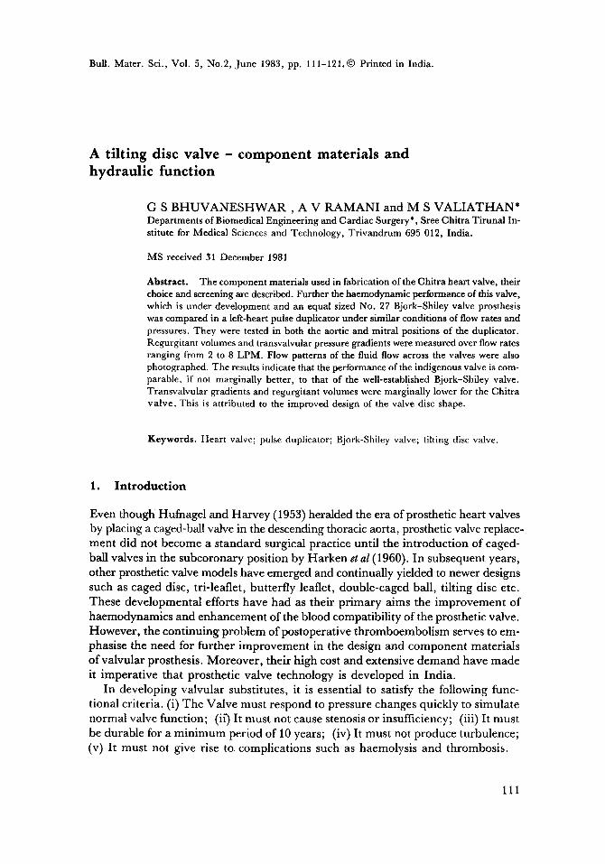
The Chitra heart valve under development here is of the tilting disc design (figure 1) employing a polyacetal homopolymer (Delrin 500, E. I. Dupont de Nemours
2 f
J
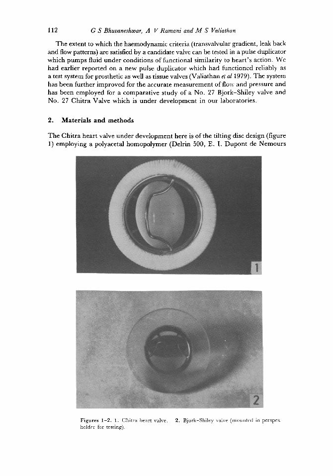
F igu res 1-2 . 1. Chi t ra heart valve. holder for testing).
2. Bjork-Shiley valve (mounted in perspex
Tilting disc valve 1 I3
and Co. Inc. U.S.A.) disc occluder, a titanium metal cage and a polyester sewing ring. The component materials were chosen for their known biocompatibility and acceptable engineering properties for use in a heart valve. Delrin is still used in the first model of the well-established Bjork-Shiley heart valve. It is inert and highly wear-resistant (Bjork 1969, 1971) and so far there are no reports of undue wear or failure even after 10 years of implant life (Fettel et a11980). The disc is injection- moulded using a heated mould to give a high surface finish and good dimensional tolerance. After moulding, the discs are stress-relieved at 160°C for 45 minutes to remove any residual moulding stresses and avoid post moulding shrinkage. They are then mechanically polished to obtain a mirror finish. The titanium used con- forms to ASTM Grade 2 commercially pure titanium. The sewing ring is made from knitted polyester surgical fabrics which have been tested extensively in dogs for tissue healing and acceptance (Bhuvaneshwar 1981). Also detailed spectroscopic investiga- tion and differential thermal analysis have been done for complete characterisation and reproducibility (Sreenivasan et al 1982).
Further all the three materials have also been tested for toxicity and biocompatibili- ty in small animals in our laboratory here (Vedanarayanan et al 1979).
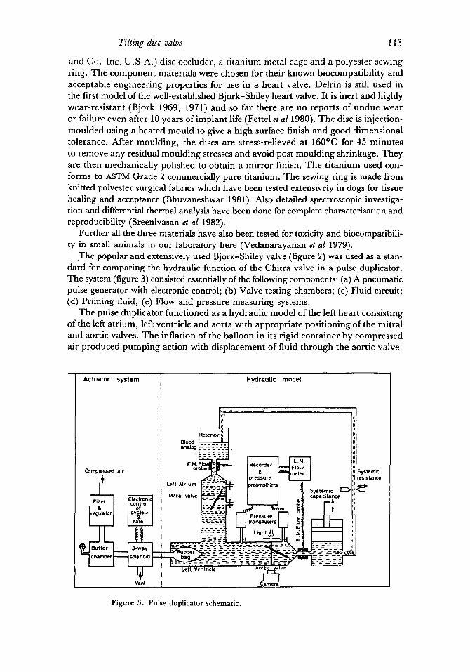
The popular and extensively used Bjork-Shiley valve (figure 2) was used as a stan- dard for comparing the hydraulic function of the Chitra valve in a pulse duplicator. The system (figure 3) consisted essentially of the following components: (a) A pneumatic pulse generator with electronic control; (b) Valve testing chambers; (c) Fluid circuit; (d) Priming fluid; (e) Flow and pressure measuring systems.
The pulse duplicator functioned as a hydraulic model of the left heart consisting of the left atrium, left ventricle and aorta with appropriate positioning of the mitral and aortic valves. The inflation of the balloon in its rigid container by compressed air produced pumping action with displacement of fluid through the aortic valve.
Actuator system Hydraulic modet
I.~'<il I Pl Blood ~ tl =na=og k--'- ~-:--=-].
Systemic q' ~ Mitral valve ~ ' [ I 1 5capact . . . . ~"]1'1
:I
Systemic ~sistance ~t
Figure 3. Pulse duplicator schematic.
114 G S Bhuvaneshwar, A V Ramani and M S Valiathan
Deflation of the balloon by venting to atmosphere caused the pump chamber to fill with fluid inflow through the mitral valve. TKe valve testing chambers are machined from a transparent plastic and provide cross-sectional areas analogous to the flow tracts in the human heart (Wieting et a11969). Pressure taps for measuring the pressure gradients across the valve are placed on either side of the valve.
A pair of Statham p23Db pressure transducers connected v/a 18 G hypodermic needles and short equal lengths of polyethylene tubing to the pressure taps provided atrial and ventricular or ventricular and aortic pressures as required. The outputs of the transducer preamplifiers were electronically subtracted to provide the pressure gradients. The pressure measurement system was matched to less than ± 0.1 mm Hg differential pressure and the accuracy can be safely expected to be within ± 0.3 mm Hg. Electromagnetic flow probes mounted as indicated in figure 3 provided the flow signal. These were recorded on an oscillographic pen recorder with a 100 Hz response.
As a preliminary, a steady flow test was performed on the two valves for comparing the orifice effect of valves. At flow rates from 2 to 20 LPM, the transvalvular pressure gradient was measured for each valve.
Pulsatile tests at 60 pulses per rain at cardiac outputs ranging from 2 to 8 LPM were carried out on the valves in both the aortic and mitral positions. The aortic pressure was adjusted to approximately 120/80 mm Hg at the required flow rate in each case with a~ustments of systemic resistance and compliance. Transvalvular pressure gradients and flows were recorded. Mean flows were measured by timed collection of the outflow.
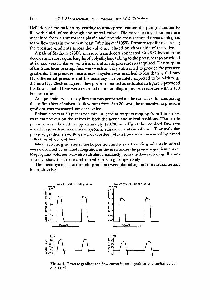
Mean systolic gradients in aortic position and mean diastolic gradients in mitral were calculated by manual integration of the area under the pressure gradient curve. Regurgitant volumes were also calculated manually from the flow recording. Figures 4 and 5 show the aortic and mitral recordings respectively.
The mean systolic and diastolic gradients were plotted against the cardiac output for each valve.
No. 27 Bji$rk - Shiley valve mmHg 2O
E 15
o~ 10
i ' ,~ o
v "5
No.27 Chitra hear t valve mmHe 2O
en 10
~o
15 <-10
t 1 Second I I 1 Second I
LPM LPM
u 10 ~o
Figure 4. Pressure gradient and flow curves in aortic position at a cardiac output
of 5 LPM.
Tilting disc valve 115
mmH 2O
15,
~ 10,
~o
~-1o X
No.27 BjSrk-
1 Second
5hi[ey valve
I
No.Z7 Chitra heart valve
m m H g 20
'6 10
=*5
1 Second
= ~ o -~ o
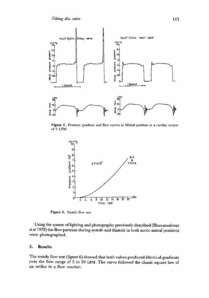
Figure 5. Pressure gradient and flow curves in Mitral position at a cardiac output of 5 LPM.
mm Hg 10-
9-
E ._~ "o
o_2
1
o I
B-S &
hitra
2 4 6 a 10 1'2 1~ 1~ 1~ ~LPM Flow rate
Figure 6. Steady flow test.
Using the system of lighting and photography previously described (Bhuvaneshwar et a11978) the flow patterns during systole and diastole in both aortic mitral positions were photographed.
3. Results
The steady flow test (figure 6) showed that both valves produced identical gradients over the flow range of 2 to 20 LPM. The curve followed the classic square law of an orifice in a flow conduit.
116 G S Bhuvaneshwar, A V Ramani and M S Valiathan
mmHg
'i ~6
o- 4
I£ 2
1
0
Chitra
. . . . . . . . . . LPM 1 2 3 4 5 6 7 8 9 10
Cardiac output
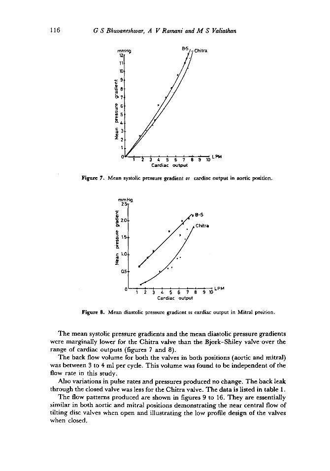
Figure 7. Mean systolic pressure gradient vs cardiac output in aortic position.
mmHg 2.5
E ._~
2.0
P o .
c 1.0-
0.5-
y• B-S
C hitra
Cardiac output
Figure 8. Mean diastolic pressure gradient vs cardiac output in Mitral position.
The mean systolic pressure gradients and the mean diastolic pressure gradients were marginally lower for the Chitra valve than the Bjork-Shiley valve over the range of cardiac outputs (figures 7 and 8).
The back flow volume for both the valves in both positions (aortic and mitral) was between 3 to 4 ml per cycle. This volume was found to be independent of the flow rate in this study.
Also variations in pulse rates and pressures produced no change. The back leak through the closed valve was less for the Chitra valve. The data is listed in table 1.
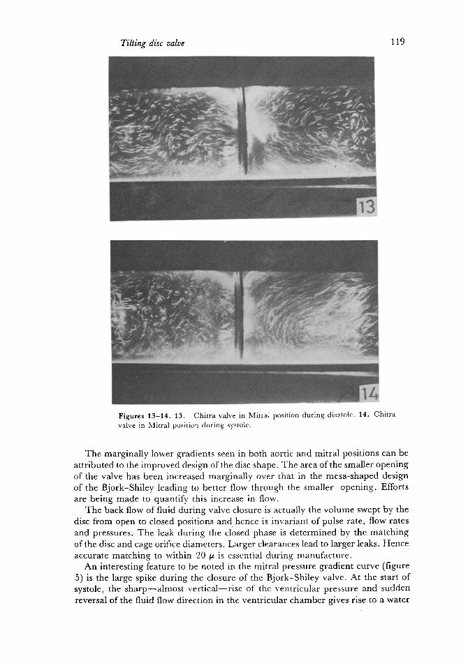
The flow patterns produced are shown in figures 9 to 16. They are essentially similar in both aortic and mitral positions demonstrating the near central flow of tilting disc valves when open and illustrating the low profile design of the valves when closed.

Tilting disc valve
Table 1. Regurgitation per cycle.
Bjork-Shiley Chitra
Aortic position
Back flow for valve closure 4.4 3,9
Diastolic leak 9.4 3.8
Total regurgitation 13.8 7.7
Mitral position
Back flow for valve closure 3.2 3.5
Systolic leak 3.5 2.0
Total regurgitation 6.7 5.5
117
Figures 9-10. 9. Chitra valve in aortic position during systole. 10. Chitra valve in aortic position during diastole.
118 G S Bhuvaneshwar, A V Ramani and M S Valiathan
11
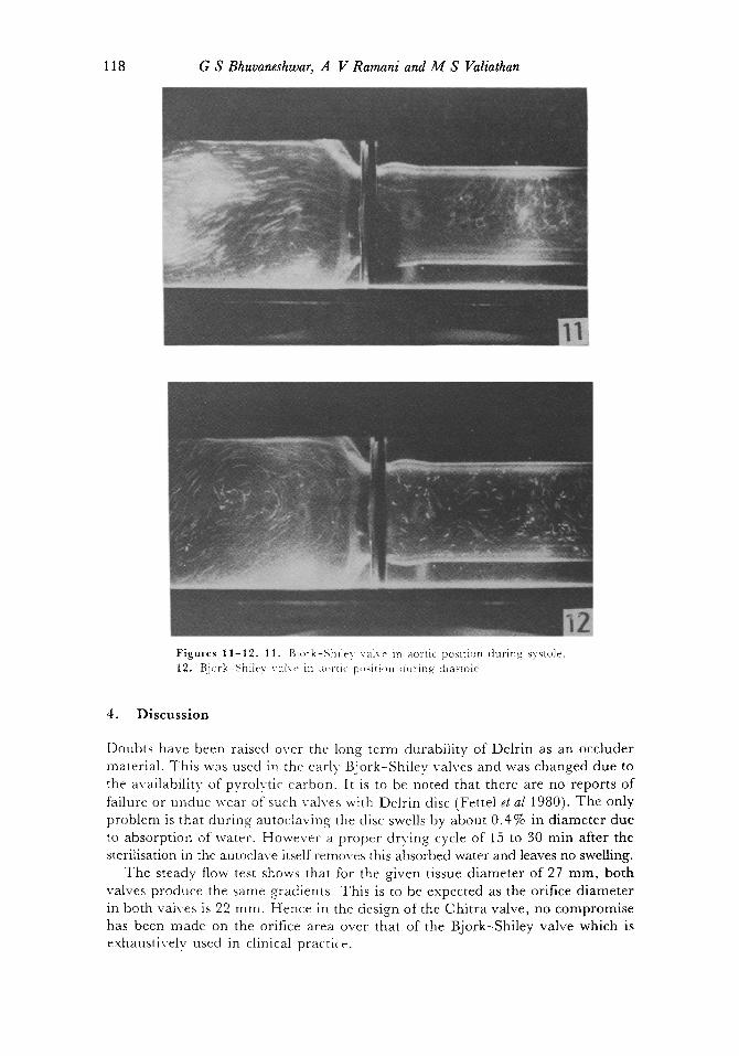
vu','~ Figures 11-12. 11. Bjork-Shlley valve in aortic postticm during systole. 12. Bj<wk-Shiley val~e in m,rtic p,,~iti,~n (hiring dlas~c)le.
4. D i s c u s s i o n
Doubts have been raised over the long term durability of Delrin as an occluder material. This was used in the early' Bjork-Shiley valves and was changed due to the availability of pyrolytic carbon. It is to be noted that there are no reports of failure or undue wear of such valves with Delrin disc (Fettel et al 1980). The only problem is that during autoclaving the disc swells by about 0.4% in diameter due to absorption of water. However a proper drying cycle of 15 to 30 min after the sterilisation in the autoclave itself removes this absorbed water and leaves no swelling.
The steady flow test shows that for the given tissue diameter of 27 mm, both valves produce the same gradients. This is to be expected as the orifice diameter in both valves is 22 ram. Hence in the design of the Chitra valve, no compromise has been made on the orifice area over that of the Bjork-Shiley valve which is exhaustively used in clinical practice.
Tilting disc valve 119
Figures 13-1t. t3. Chitra valve in Mitral position during diastole. 14. Chitra valve in Mitral position during systole.
The marginally lower gradients seen in both aortic and mitral positions can be attributed to the improved design of the disc shape. The area of the smaller opening of the valve has been increased marginally over that in the mesa-shaped design of the Bjork-Shiley leading to better flow through the smaller opening. Efforts are being made to quantify this increase in flow.
The back flow of fluid during valve closure is actually the volume swept by the disc from open to closed positions and hence is invariant of pulse rate, flow rates and pressures. The leak during the closed phase is determined by the matching of the disc and cage orifice diameters. Larger clearances lead to larger leaks. Hence accurate matching to within 20 ~ is essential during manufacture.
An interesting feature to be noted in the mitral pressure gradient curve (figure 5) is the large spike during the closure of the Bjork-Shiley valve. At the start of systole, the sharp--a lmost vert ical--r ise of the ventricular pressure and sudden reversal of the fluid flow direction in the ventricular chamber gives rise to a water
~120 G S Bhuvaneshwar, A V Ramani and M S Valiathan
4
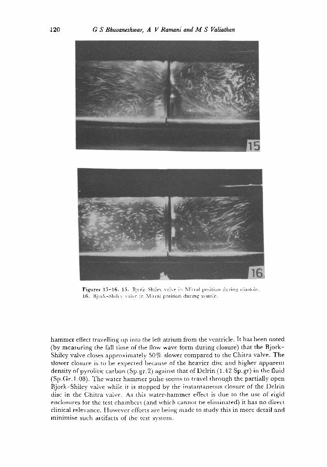
Figures 15-16. 15. Bjork-Shiley valve in Nlitral position during diastole. 16. Bjork-Shlley valve in Mitral position during systole.
hammer effect travelling up into the left atrium from the ventricle. It has been noted (by measuring the fall time of the flow wave form during closure) that the Bjork- Shiley valve closes approximately 50 % slower compared to the Chitra valve. The slower closure is to be expected because of the heavier disc and higher apparent density of pyrolitic carbon (Sp. gr. 2) against that of Delrin (1.42 Sp. gr) in the fluid (Sp.Gr. 1.08). The water hammer pulse seems to travel through the partially open Bjork-Shiley valve while it is stopped by the instantaneous closure of the Delrin disc in the Chitra valve. As this water-hammer effect is due to the use of rigid enclosures for the test chambers (and which cannot be eliminated) it has no direct clinical relevance. However efforts are being made to study this in more detail and minimise such altifacts of the test system.

Tilting disc valve 121
5. Conclusion
T h e resul ts i nd ica t e tha t the p e r f o r m a n c e ol the i n d i g e n o u s va lve is c o m p a r a b l e i f no t m a r g i n a l l y b e t t e r t h a n tha t o f the well e s t ab l i shed B j o r k - S h i l e y va lve .
T r a n s v a l v u l a r g r a d i e n t s a n d r e g u r g i t a n t v o l u m e s were m a r g i n a l l y lower for the
C h i t r a valve . T h i s is a t t r i b u t e d to the i m p r o v e d des ign o f the va lve disc shape .
References
Bjork V O 1969 Stand. Thorac. Cardiovasc. Surg. 3 1 Bjork V O 1971 Scand. J. Thorac. Cardiovasc. Surg. 5 87 Bhuvaneshwar G S, Venkatesan V S and Valiathan M S 1978 A pulse duplicator for in vitro
evaluation of prosthetic heart valves presented at Int. Syrup. and Workshop on Biomedical Engg., New Delhi
Bhuvaneshwar G S, Venkatesan V S, Patankar V L, Kartha C C, Arthur V, Lal G and Valiathan M S Indian J. Med. Res. 14 580
Fettel B E, Johnston D R and Morris P E 1980 Medical instrumentation 14 161 Harken D E, Soroff H S, Taylor W J, Lefemin, Gupta S K and Lunzer S 1960J. Thorac. Car-
diovasc. Surg. 40 744 Hufnagel C A and Harvey P 1953 Bull. Georgetown. Univ. 6 60 Sreenivasan K, Prabha D and Bhujile V V 1982 Bull. Mater. Sct. 5 123 Valiathan M S, Bhuvaneshwar G S and Venkatesan V S 1979 IndianJ. Surg. 40 283 Vedanarayanan P V, Rathinam K and Fernandez A C 1979 Preliminary investigations on the
biocompatibility/safety of three candidate materials intended for the fabrication of a prosthetic heart valve. Presented at the 31st Indian Pharmaceutical Congress, Baroda
Wieting D W, Hall C W, Liotta D and DeBakey M E 1969 Prosthetic heart valves (ed) L A Brewer (Springfield: Charles C Thomas) Ch. 4, p. 34


![Hydrodynamic calculation Butterfly valve (lenticular disc) [EN] calculation Butterfly valve... · Hydrodynamic calculation Butterfly valve (lenticular disc)!=0,262’ (=1,15’ Fig.1](https://img.pdfslide.us/doc/110x75/5e4d4893a5620b2b3175568a/hydrodynamic-calculation-butterfly-valve-lenticular-disc-en-calculation-butterfly.jpg)