Embed Size (px)
Citation preview

2007-08
Study Tour Report
Report submitted to-
Chief Engineer & Director, Maharashtra Engineering Training Academy, Nashik Duration: (26/05/2008-08/06/2008)

qÉWûÉUÉ·í AÍpÉrÉÉÇ̧ÉMüÐ mÉëÍzɤÉhÉ mÉëoÉÉåÍkÉlÉÏ
lÉÉÍzÉMü -422004
Maharashtra Engineering Training Academy, Nashik
xÉUVû xÉåuÉÉ pÉUiÉÏlÉå ÌlÉrÉÑ£üÏ ÌSsÉåsrÉÉ xÉWûÉrrÉMü MüÉrÉïMüÉUÏ AÍpÉrÉÇiÉÉ ´ÉåhÉÏ-1 AÍkÉMüÉîrÉÉÇxÉÉPûÏ ¤Éå§ÉÏrÉ
mÉëÍzɤÉhÉ MüÉrÉï¢üqÉ, eÉsÉxÉÇmÉSÉ ÌuÉpÉÉaÉ Field Training for Direct Recruits - Assistant Executive Engineer (Grade 1) of
Water Resource Department.
MüÉsÉÉuÉkÉÏ: 26 qÉå iÉå 08 eÉÑlÉ 2008 Duration: 26 May to 08 June 2008
“AprÉÉxÉ SÉæUÉ AWûuÉÉsÉ” “STUDY TOUR REPORT”
xÉÉSUMüiÉÉï-
mÉëÌuÉhÉ MüÉåsWåû, oÉÏ.D.(ÍxÉÎuWûsÉ), LqÉ.OåûMü. (AÉrÉ. AÉrÉ. OûÏ.- MüÉlÉmÉÔU)
(xÉWûÉrrÉMü MüÉrÉïMüÉUÏ AÍpÉrÉÇiÉÉ)
Submitted by-
Pravin Kolhe, BE (Civil), MTech (IIT-Kanpur) (Assistant Executive Engineer)

Executive Summary & Acknowledgement
aharashtra Engineering Training Academy (META), Nashik organized training program for direct recruits - Assistant Executive Engineer & Assistant Engineer (Class I) of Water
Resource Department (WRD), in accordance with Maharashtra Engineering Service Examination-2004. As per schedule of training program, we were directed to undergo Study Tour from 26th May to 08 June 2008. Shri. Pawar saheb was with us during this tour and we visited several projects and we were fortunate to participate in this tour. This report includes the details of projects which we visited during the Study tour.
I take this opportunity to express my gratitude to those whose active help and support makes this report possible in the present form.
First of all, I express my sincere gratitude to Shri. N. B. Ghuge Saheb, Chief Engineer and Director, Maharashtra Engineering Training Academy, Nashik for insisting in me the drive to work hard and for inculcating in me the discipline to think clearly.
It is the endless guidance and constant encouragement of Shri. Bairagi Saheb, Superintending Engineer and Joint Director META, Shri Pawar Saheb and Shri. Kulkarni Saheb, Executive Engineer and I would like to express my heartfelt gratitude to them.
Definitely the knowledge, I received during this study tour was a lifetime experience and it will serve as a foundation for my career in Water Resources Department.
Last, but not least, I wish to express my gratitude towards my
parents- Shivaji and Rohini, my grandparents- Rangnath and Sitabai, my uncle Raosaheb and aunty Radhika who sacrificed a lot to give me a good education.
- Pravin Kolhe BE (Civil), MTech (IITK) (Assistant Executive Engineer)
M

Table of Content
Chapter 1. About Study Tour ...................................................................................................................... 3
1.1 Study Tour Schedule ........................................................................................................................... 3
Chapter 2. Ukai Project ................................................................................................................................. 4
2.1 Salient Features of Ukai Project ..................................................................................................... 4
2.2 Hydrology ................................................................................................................................................ 4
2.3 Reservoir .................................................................................................................................................. 4
2.4 Salient Features of Dam .................................................................................................................... 5
2.5 Spillway .................................................................................................................................................... 5
2.6 Power House .......................................................................................................................................... 5
Chapter 3. Sardar Sarovar Project ............................................................................................................ 6
3.1 About Narmada Basin and Narmada River ................................................................................. 6
3.2 Need For Sardar Sarovar Project ................................................................................................... 6
3.3 Main Features of Dam ......................................................................................................................... 7
3.4 Main Features of Power House ...................................................................................................... 7
3.5 Main Features of Canal System ..................................................................................................... 8
3.6 Narmada Water Dispute Tribunal (NWDT) Award .................................................................. 8
3.7 Definition of NWDT .............................................................................................................................. 9
3.8 Decisions of NWDT ............................................................................................................................... 9
3.9 Quality Control at Sardar Sarovar Project ............................................................................... 10
3.10 Benefits from Sardar Sarovar Project ..................................................................................... 10
3.10.1 Irrigation ..................................................................................................................................... 10
3.10.2 Drinking Water Supply ........................................................................................................... 11
3.10.3 Hydro Power ............................................................................................................................... 11
3.10.4 Flood Protection ........................................................................................................................ 11
Chapter 4. Surya Project ............................................................................................................................ 12
4.1 About Surya Project .......................................................................................................................... 12
4.2 Salient Features of Surya Project ................................................................................................ 12

Field Training: Study Tour Report (26.05.2008 to 07.06.2008) ________________________________________________________________
Page 2 of 30
Chapter 5. Koyna Hydroelectric Project ............................................................................................... 14
5.1 Introduction ......................................................................................................................................... 14
5.2 About Koyna Dam ............................................................................................................................... 14
5.3 Koyna Stage I and II ........................................................................................................................ 14
5.4 Revised Capacities of Stage I and II .......................................................................................... 15
5.5 Koyna Stage III .................................................................................................................................. 15
5.6 Earthquake of 11 Dec 1967 ............................................................................................................ 16
5.7 Koyna Dam Foot Power House ...................................................................................................... 17
5.8 Water Allocation ................................................................................................................................. 17
5.9 Stage IV .................................................................................................................................................. 17
5.10 Stage IV – Extension of HRT (Stage 4 B)............................................................................... 18
5.11 Koyna Reduced Level (KRL) ........................................................................................................ 18
5.12 Salient Features of Koyna Dam .................................................................................................. 18
5.13 Salient Features of Kolkewadi Dam ......................................................................................... 19
5.14 Stage wise generation ................................................................................................................... 19
Chapter 6. Urmodi Project ......................................................................................................................... 20
6.1 Salient Features .................................................................................................................................. 20
6.2 Salient Featurs .................................................................................................................................... 21
Chapter 7. Nira-Devdhar Project ............................................................................................................. 22
7.1 Salient Features .................................................................................................................................. 22
Chapter 8 Bhama-Aaskhed Project ........................................................................................................ 25
8.1 General Information ......................................................................................................................... 25
8.2 Details of Dam ..................................................................................................................................... 25
Chapter 9 Bhandardara Project ............................................................................................................... 26
9.1 Salient Features .................................................................................................................................. 26
Chapter 10 Nilwande Project .................................................................................................................... 28
10.1 Salient Features ............................................................................................................................... 28
Chapter 11 Conclusion ................................................................................................................................. 29

Field Training: Study Tour Report (26.05.2008 to 07.06.2008) ________________________________________________________________
Page 3 of 30
Chapter 1. About Study Tour
1.1 Study Tour Schedule
As a part of training programme, ‘Study Tour’ was scheduled from 26th May to 7th June 2008. The tour started from Maharashtra Engineering Training Academy ,Nashik on 26th May 2008 at 8:00 AM. Shri. Pawar, Executive Engineer was with us during the tour.
We visited number of projects and details are given below-
Date Project Location 26 May 2008 Prakasha Barrage Village: Prakasha,
Tal: Shahada, Dist: Nandurbar 27 May 2008 Ukai Project Village: Ukai,
Tal: Songarh, Dist: 28 May 2008 Sardar Sarovar Project Kewadia Colony
Tal: Rajpipala, Dist: Narmada 29 May 2008 Sardar Sarovar Project Kewadia Colony
Tal: Rajpipala, Dist: Narmada 30 May 2008 Surya Project Suryanagar
Tal: Dahanu, Dist Thane 31 may 2008 Morve Dam Thane 01 June 2008 Bhira Project Raigadh Irrigation Division,
Tal: Kolad, Dist: Thane Kal Project Raigadh Irrigation Division,
Tal: Kolad, Dist: Thane 02 June 2008 Kolkewadi Dam Aalore, Dist: Ratnagiri Koyana Project
Stage- 4 Aalore,Dist: Ratnagiri
Koyana Project Stage- 4 (B)
Aalore,Dist: Ratnagiri
03 June 2008 Koyana Dam Koyana Nagar, Dist: Satara Urmodi Project Dist: Satara Dhom-Balakawadi Project Tal: Wai, Dist: Satara Dhom Project Tal: Wai, Dist: Satara 04 June 2008 Nira-Devdhar Project Bhatghar Project Tal: Bhor, Dist: Pune 05 June 2008 Bhama-Aaskhed Project 06 June 2008 Bhandardara Project Tal; Akole, Dist: Ahmednagar Nilwande Project Tal; Akole, Dist: Ahmednagar
This report includes details of all the projects, which we visited.

Field Training: Study Tour Report (26.05.2008 to 07.06.2008) ________________________________________________________________
Page 4 of 30
Chapter 2. Ukai Project
2.1 Salient Features of Ukai Project
State Gujarat District Surat Taluka Songad Village Ukai River Tapi
2.2 Hydrology Catchment area At Ukai 62225 km2
At Kakrapara 62308 km2
At Surat 63823 km2
At Kathor bridge 64100 km2 Mean avg. rainfall in the water shed 785 mm Maximum annual rainfall in the watershed 1191 mm Minimum annual rainfall in the watershed 270 mm Mean annual runoff at dam site 17220 Mm3 Observed maximum flood at dam site (Aug 1968) 42470 m3/s Maximum regulated outflow from reservoir 24100 m3/s 2.3 Reservoir
Gross storage capacity At FRL 8511 MCM Dead storage below RL 82.296 1142 MCM Live storage 7369 MCM Full reservoir level 105.156 m Cultivated land submerged 30350 ha Other land submerged 7485 ha Forest land submerged 22260 ha Villages affected by submergence 170 nos High flood level 106.99 m Length of reservoir 112 km

Field Training: Study Tour Report (26.05.2008 to 07.06.2008) ________________________________________________________________
Page 5 of 30
2.4 Salient Features of Dam
Length of masonry section (including spillway) 868.83 m
Length of earthen dam section 4057.96 m Total length 4926.79 Earth dam above river bed 68.58 m
Masonry dam above deepest foundation level 80.772 m
Total earth work 23240 * 10 6 m3 Total quantity of masonry concrete 1484 * 10 3 m3 Top of dam 111.252 m Road width on spillway 6.706 m
2.5 Spillway Crest level of spillway 91.135 m Length of spillway 425.195 m Top of crest level 105.461 m Type of gate Radial Size of gate 15.545 * 14.783 m Nos of gate 22 gates Discharging capacity from all 22 gates At FRL – 345 ft AT HFL – 351 ft
13.37 lakh cusec 16.34 lakh cusec
2.6 Power House
Size of penstock 4 nos 7.01 m dia Installation of 4 units of 75 MW each 300 MW
Generation at 35 load factor 193 MW Annual energy 670 * 10 8 K WH
CANAL BED POWER HOUSE
Size of penstock 3.96 * 2.05 m Installation of 2 units of 2.5 MW each 5 MW
Type of hoist hydraulic hoist Discharge through each unit 550 cusecs

Field Training: Study Tour Report (26.05.2008 to 07.06.2008) ________________________________________________________________
Page 6 of 30
Chapter 3. Sardar Sarovar Project
3.1 About Narmada Basin and Narmada River
The Narmada, the largest flowing Westward, rises near Amarkantak range of mountains in Madhya Pradesh. It is the fifth largest river in the country and the largest one in Gujarat. It traverses Madhya Pradesh, Maharashtra and Gujarat and meets the Gulf of Cambay. The total length of the river from source to sea is 1312 kilometers (815 miles) while the length up to dam site is 1163 kilometers. (723 miles). The width of the river channel at dam site during high floods is 488 meter (1600 feet) and that during summer is 45.70 meter. (150 feet). The maximum recorded flood on 7th September 1994 was 70,847 cusecs (2.5 million cusecs) while minimum recorded flow in summer was 8.5 cusecs (300 cusecs.) The dam is designed for 87,000 cusecs (3.07 million cusecs) flood.
The total basin area of the river is 97,410 square kilometer comprising 85,858 square kilometer in Madhya Pradesh, 1658 square kilometer in Maharashtra and 9894 square kilometer in Gujarat. The drainage area up to dam site is 88,000 square kilometer. The mean annual rainfall in the basin is 112 centimeters. The annual run of the dam site at 75 percentage of dependability is 27.22 MAF. The World Bank computed the yield of 28.57 MAF while the yield computed in May 1992 by the Central Water Commission, Government of India is of 26.60 MAF, i.e. about 27.00 MAF. The utilisation of Narmada River basin today is hardly about 10%. Thus water of the Narmada continue to flow to the sea unused. 3.2 Need For Sardar Sarovar Project
Post 2nd World War 20th Century is marked by end of colonial era. Countries - small and big, after attaining political freedom, embarked on ambitious programme of economic development. The twin problem of under employment and poverty has been the most difficult challenge they have been facing. They are no doubt endowed with diverse natural resources, which have remained unharnessed. Burgeoning population has thrown up army of unemployed young people who are asset if gainfully used, but an explosive liability if kept idle. The crucial task for the planners and leaders of these countries is to channelise the unharnessed natural resources - land, water, minerals, forests, sea wealth and so on and the idle manpower so as to transform them into productive wealth for the people.

Field Training: Study Tour Report (26.05.2008 to 07.06.2008) ________________________________________________________________
Page 7 of 30
3.3 Main Features of Dam Dam
1 Length of main concrete gravity dam 1210.00 m 2 Maximum height above deepest foundation level 163.00 m 3 Top R.L. of dam. 146.50 m 4 Catchments area of river above dam site 88,000 Sq. km 5 Live storage capacity 0.58M.Ha.m (4.7 MAF) 6 Length of reservoir
Maximum width Average Width
214.00 km 16.10 km 1.77 km
7 Spillway gates Chute Spillway Service Spillway
7 Nos. 60' x 60' 23 Nos. 60' x 55'
8 Spillway Capacity 84949.25 cumecs (30 lakh cusecs)
3.4 Main Features of Power House Power Houses
1 River bed power house 1200 MW 2 Canal head power house 250 MW
There are two power houses for the Sardar Sarovar Project (SSP). (i) 1200 MW River Bed Power House and (ii) 250 MW Canal Head Power House. Power benefits are shared among Madhya Pradesh, Maharashtra and Gujarat in the ratio of 57:27:16 respectively.
River Bed Power House
Canal Head Power House

Field Training: Study Tour Report (26.05.2008 to 07.06.2008) ________________________________________________________________
Page 8 of 30
3.5 Main Features of Canal System Canal System
Main Canal 1 Full supply level (F.S.L.) at H.R. 91.44 m (300 ft) 2 Length upto Gujarat - Rajasthan border 458.00 km 3 Base width in head reach 73.01 m 4 Full supply depth (F.S.D.) in head reach 7.60 m 5 Design discharge capacity
(1) In head reach 1133 cumecs (40,000 cusecs)
(2) At Gujarat Rajasthan border 71 cumecs (2,500 cusecs)
Narmada Main Canal is a contour canal. It is the biggest lined irrigation canal in the world. It is about 458 km. long up to Gujarat -Rajasthan border. It has a capacity to flow 1133 cumecs (40000 cusecs) at its head-at kevadia and reducing to 71 cumecs (2500 cusecs) at the Gujarat -Rajasthan border. The canal extends further in the state of Rajasthan to irrigate areas in Barmer and Jhalore districts of Rajasthan. The cross section of the canal, at its head is 73.1m x 7.6m (Bed width x Full supply depth), with 2:1 inner side slope. It has a velocity of water in the initial reach is 1.69 m/sec. The Main Canal is lined with plain cement concrete to minimise sippage losses to attain higher velocity and to control the water logging in future. The lining work is carried out with the mechanized pavers. Such a large scale paving of concrete lining is done for the first time in India. 3.6 Narmada Water Dispute Tribunal (NWDT) Award
The plan for harnessing the river for irrigation and power generation in the Narmada basin, was initiated in 1946. Seven projects including the Bharuch project were identified during the initial survey, and 4 projects- Bharuch (Gujarat), Bargi, Tawa and Punasa in Madhya Pradesh- were given top priority for investigation. After the completion of investigation, the proposed dam at Gora in Gujarat with the full reservoir level (FRL) 161 feet (49.80metres) was selected and the foundation stone was laid by Pandit Jawaharlal Nehru on 5th April, 1961. However, as more detailed and modernised contour sheets from the Survey of India were available , the possibility of raising the height of the dam, for optimum utilisation of water, was considered.
In 1964, to resolve the dispute about sharing of the Narmada Water between the governments of Gujarat and Madhya Pradesh, the government of India appointed an expert committee under the Chairmanship of late Dr. Khosla which recommended a higher dam with FRL 500 feet (152.44metre) in 1965. However, no agreement could be arrived at and the Narmada Water Dispute

Field Training: Study Tour Report (26.05.2008 to 07.06.2008) ________________________________________________________________
Page 9 of 30
Tribunal (NWDT) was constituted by the Government of India in 1969, under the Inter State River Water Disputes Act, 1956. 3.7 Definition of NWDT In 1964, to resolve the dispute about sharing of the Narmada Water between the governments of Gujarat and Madhya Pradesh, the government of India appointed an expert committee under the chairmanship of late Dr. Khosla, which recommended a higher dam with FRL 500 feet. (152.44metres) in 1965. However, the Government of Madhya Pradesh did not accept the Khosla Committee report and the plan utilising Narmada Water proposed by that Committee. Thereafter the then Union Minister of Irrigation, Dr. K. L. Rao made efoorts to bring about agreement amongst the riparian states, which also did not succeed. Therefore, the Narmada Water Dispute Tribunal (NWDT) was constituted by the Government of India in 1969, under the Inter State River Water Disputes Act, 1956. The NWDT was headed by sitting judge of the Supreme Court of India, the other two member being member of two High Court. 3.8 Decisions of NWDT 1 Allocation of water : (A 75% dependable yields)
Allocation in MAF Madhya Pradesh 18.25 Gujarat 9.00 Maharashtra 0.25 Rajasthan 0.50
Total : 28.00
2 Height of the dam : FRL at RL 455.00 feet (138.68 meters) MWL at RL 460.00 feet (140.21 meters)
3 Full Supply Level of the Main Canal. FSL at RL 300.00 feet (91.44 metres)
4 Power allocation Allocation in Percent Madhya Pradesh 57 Maharashtra 27 Gujarat 16
There would be regulated releases from Narmada Sagar Project (NSP) about 300 km. upstream in Madhya Pradesh. It was also decided that the Main Canal is to be extended upto the Rajasthan border for irrigation to the drought prone areas of 75,000 ha. in Barmer and Jhallore district of Rajasthan.

Field Training: Study Tour Report (26.05.2008 to 07.06.2008) ________________________________________________________________
Page 10 of 30
According to the Award of NWDT, the parameters of Sardar Sarovar dam will neither be reviewed nor changed till 2025 A.D. i.e. 45 years after the notification of the Award. The award is binding on all the concerned parties. 3.9 Quality Control at Sardar Sarovar Project Sardar Sarovar Project (SSP) is a multipurpose river valley project currently under construction across the river Narmada to irrigate 17.92 lakh hectare annually in the State of Gujarat. The main dam and hydropower works are under progress. The construction work of various canals of SSP, Gujarat State is in full swing. The Narmada Main Canal (NMC) of the SSP is the largest irrigation lined canal in the world. The total length of NMC is 458 km. having a capacity of 1133 cumecs (40,000 cusecs) at head and 71 cumecs (2500 cusecs) at tail. The NMC and its branch canals in Phase-I (ch. O to 144.5 km.) are completed whereas works of distribution system are nearing completion. The NMC works in Phase-II A (Ch. 144.5 km. to 264 km.) are also almost completed and its branches are under progress. The NMC works in Phase-II B (i.e. Ch. 264 km to 357 km) are in progress and planned to be completed by September, 2003 and its branch canals are under progress. The work of Saurashtra Branch Canal (total length 104 km.) and its branches are under progress and the work of Kutch Branch Canal (total length 307 km.) are to be taken up shortly. Thus, large quantum of canal works are to be taken up shortly by SSP. 3.10 Benefits from Sardar Sarovar Project
3.10.1 Irrigation
The Sardar Sarovar Project will provide irrigation facilities to 18.45 lac ha.
of land, covering 3112 villages of 73 talukas in 15 districts of Gujarat. It will also irrigate 75,000 ha. of land in the strategic desert districts of Barmer and Jallore in Rajasthan and 37,500 ha. in the tribal hilly tract of Maharashtra through lift. About 75% of the command area in Gujarat is drought prone while entire
Irrigation
Drinking Water Supply
Hydro Power
Flood Protection

Field Training: Study Tour Report (26.05.2008 to 07.06.2008) ________________________________________________________________
Page 11 of 30
command (75,000 ha.) in Rajasthan is drought prone. Assured water supply will soon make this area drought proof. 3.10.2 Drinking Water Supply
A special allocation of 0.86 MAF of water has been made to provide
drinking water to 135 urban centres and 8215 villages (45% of total 18144 villages of Gujarat) within and out-side command in Gujarat for present population of 18 million and prospective population of over 40 million by the year 2021. All the villages and urban centres of arid region of Saurashtra and Kachchh and all "no source" villages and the villages affected by salinity and fluoride in North Gujarat will be benefited. Water supply requirement of several industries will also be met from the project giving a boost to all-round production 3.10.3 Hydro Power
There will be two power houses viz. River bed power house and canal head power house with an installed capacity of 1200 MW and 250 MW respectively. The power would be shared by three states - Madhya Pradesh - 57%, Maharashtra - 27% and Gujarat 16%. This will provide a useful paking power to western grid of the country which has very limited hydel power production at present. A series of micro hydel power stations are also planned on the branch canals where convenient falls are available. 3.10.4 Flood Protection
It will also provide flood protection to riverine reaches measuring 30,000 ha. covering 210 villages and Bharuch city and a population of 4.0 lac in Gujarat.

Field Training: Study Tour Report (26.05.2008 to 07.06.2008) ________________________________________________________________
Page 12 of 30
Chapter 4. Surya Project
4.1 About Surya Project Surya Irrigation Project is Constructed across the river Surya near village Dhamni in Jawhar taluka of Thane District. This project consists of:
Main storage Dam near village Dhamni. Pickup weir at 8 Km downstream of main dam near village Kavdas. 28.51 Km long right bank canl and 47 Km long left bank canal from the pickup weir.
Hydro-electric power station of 6 MW capacity at the foot of main dam. Hydro-electric power station of 750 KW capacity on right bank in Km 28.51 which will be operated on 13 m fall.
After completion of this project 14696 Hectors of agricultural land will be irrigated. Taluka wise area irrigated is as under. • Jawhar taluka - 30 Ha • Dahanu Taluka - 6125 Ha • Palghar taluka - 8541 Ha. 4.2 Salient Features of Surya Project Purpose Drinking purpose Cultural use Irrigation use Industrial use Power generation Inflow Source Catchment Area 203.30 Km2
Mean annual runoff 474 mm3
Mean annual rainfall 3233 mm
Dam Construction Period 1978-1990 Type Masonry Dam Max height at R.B.L. 58.08 m Length at top 695m Location River Surya Village Dhamni

Field Training: Study Tour Report (26.05.2008 to 07.06.2008) ________________________________________________________________
Page 13 of 30
Taluka Jawahar District Thane State Maharashtra Reservoir Area at FSL 16.77 km2 Gross Storage 285.31 mm3 Live Storage 276.35 mm3 Spillway Gates Type Radial Numbers 5 Size 12m x 8m Energy dissipater Flip bucket Spillway Type Ogee Length 72 m QMax 3180 m3/sec
Canals LBC RBC Length (km) 28.51 47 Capacity (m3/s) 21.81 10.78 GCA (Ha) 30547 CCA (Ha) 14696 Power Generation Location Dhamani Sakhare Turbine type Kaplan Francis Units One One Capacity 6 MW 0.75 MW Head 37 m 12.5 m Qmax (cumecs) 16.89 7.50 Land Acquired (Hectors) Type of Land For Dam &
Submergence For Canals
For Colonies, Roads & Other purpose
Total Land aquired
Forest 1095.394 324.552 - 1419.94 Government - 3293 203 232.93 Private waste 1078.41 856.89 - 1935.30 Private cultivable
- - - -
Total 2173.804 1214.372 203 3591.17

Field Training: Study Tour Report (26.05.2008 to 07.06.2008) ________________________________________________________________
Page 14 of 30
Chapter 5. Koyna Hydroelectric Project
5.1 Introduction The koyna river rises near Mahableshwar in the Sahyadri hill ranges and flows in a north-south direction almost parallel to the Arabian sea coast for a distance of 65 km from Mahableshwar to Helwak. Then near village Helwak, Tal. Patan, Dist. Satara, it turns sharply eastwards to join river Krishna at karad which is 56 km from dam site. Unlike the other rivers rising in the Deccan Plateau which flow in an eastern or south-western direction and therefore attracts high rainfall only at their source. The koyna flowing alongside the mountains and parallel to the Arabian Sea for more than half its course, catches in its deep boat like basin a rainfall of well over 5080 mm (200”) a year for a length of 60 km. Water is impounded by the Koyna dam from the catchment area of about 891.78 sq km. 5.2 About Koyna Dam This is a straight gravity dam. The type of construction used for the main dam is a unique one, with the use of rubble concrete. It may be mentioned that it is not a concrete dam but a sort of mechanised masonry or so called rubble concrete dam on the lines of such types of dams constructed on Ocker river in Germnay. The dam is 807.72 m in length at the top and impounds a reservoir with a gross capacity of 2796.5 Mm3. Six radial gates each 12.5 x 7.62 m have been installed in the spillway portion, which is located in the gorge. The energy dissipation is effected in a stilling basin. 5.3 Koyna Stage I and II The topography of the area is very favourable for the location of Hydro Electric Project. It has a vertical drop of 487.68 m at Pophali. Between the 579 m high bed of koyna and 152 m high base on its western side, this has rendered a high head hydro electric scheme feasible at competitive cost. Since the work through which the tunnels pass is excellent basalt rock, it was possible to take advantage of this rock by transversive part of pressure of water to rock and part by steel penstocks which led to economy in the thickness. Thus koyna went underground for the sake of economy. The works of Stage I & II were started in 1954 and the first machine was commissioned in May 1962. The remaining three units of the first stage were commissioned with the time lag of about four months between successive units. Design capacity of stage I is 4 units of 60 MW each. When the project was taken up for execution it was proposed to execute the second stage with a time lag

Field Training: Study Tour Report (26.05.2008 to 07.06.2008) ________________________________________________________________
Page 15 of 30
after the completion of the first stage. Increasing power demand in the region necessitated execution of the second stage works in continuation of those of stage I. Stage II consists 4 units of 75 MW. The last of the eight machines was commissioned in June 1967. 5.4 Revised Capacities of Stage I and II
1. Industrial growth and agricultural demand is drastically increasing day by day. With a view to explore still more output from the installed unit units with minimum expenditure, it was planned to enhance capacity of stage I each unit from 60 to 65 MW. The augmentation was carried out for stage I units by increasing nozzle diameter and its stroke as well as increase in bucked width of Pelton wheel runner. The modification/uprating has been carried out under supervision of original equipment manufacturer M/s Neyrpic, France.
2. Due to continuous overloading of stage II, crisis lot of problem in Dobecon end winding cops, failure of stator winding, damages stator core at bottom side, burning of aluminium fingers and stampings etc. On reviewing results of stator winding conducted by Central Power Research Institute, Bangalore and M/s AEG, Germany, they have strongly recommended to replace existing stator winding of all four units by better quality Epithermal class ‘F’ insulation. Accordingly renovation of generator winding of stage II units was carried out under the supervision of M/s AEG, Germany. In new winding roebel bars cross section area of copper is increased by 30 % to facilitate uprating of each unit by 5 MW. As such, capacity of stage II each unit is enhanced from 75 MW to 80 MW.
3. A joint team of Engineers from CEA, PFC, BHEL & MSEB visited Koyna power station in Dec. 1989 to analyse the problems areas affecting the operation and performance of generating units. Offers from original equipment manufacturers with their recommendations were obtained. Based on this, rewinding of 4 units of 65 MW generators of stage I units and uprating of each unit to 70 MW.
5.5 Koyna Stage III The tail water of the stage I & II power house is let down at KRL 133.20 m and to utilize the balance residual head before the water goes to sea, a dam (36 Mm3) and power house is located at Kolkewadi, adjoining to Vaitarni valley to generate 320 MW with four machines of 80 MW each. The water of the stage I & II flows through Vaitarni and Vashishti rivers down to the creek at Chiplun at about KRL 14. There is an additional drop of about 120 m between the exit portal of the tail race tunnel and the creek, where the tail waters join. Thus the important feature of the stage III works is that the power house will be used as a peaking station. It is common experience that the power demand over the day is not uniform but is excessive every morning and evening. It is not possible to

Field Training: Study Tour Report (26.05.2008 to 07.06.2008) ________________________________________________________________
Page 16 of 30
cope up with the demand with the full installed capacity of all the power houses supplying base power to the grid specially Thermal Power Plants. As such Stage III Power house is a peaking power station, to be operated only peak hours. Construction of the project was started in 1966 but the earthquake of 11th Dec. 1967 hindered the progress to some extent. The designs required to be modified so that the structure could stand severe earthquakes. The first machine has comminssioned on 6.07.1975. 5.6 Earthquake of 11 Dec 1967 Koyna Hydro Electric Project dedicated to National Prosperity received unprecedented blow due to earthquake of severe intensity about 6.8 Richter scale, at 04.21 Hrs on December 11, 1967. Complete life in Pophali, Koyna and Alore area was brought to standstill. Earthquake took a toll of nearly 250 lives and many of the employees and family members were severely injured. Domestic property and equipment shattered to pieces. All the units and the 220 kV transmission lines tripped out. Western Maharashtra plugged into complete darkness, Industry in Bombay were paralysed. But sense of involvement and belongings amongst the employees kept them away from the thought of running away and the morale was very high. It was really courageous task to put the generating sets again in service. Engineers and workers rose to the occasion and without waiting for any call, rushes to Power House to attend to the equipment and to restore power supply. Units had been brought back on the line after through inspection within 3 days. By working continuously day and night, all the generating sets were brought on bars, one by one after checking for all possible faults. All the units were put to the full load capacity by 30.12.1967. For studying the earthquake phenomenon in koyna region and effects on the dam, two committees were appointed of which one was appointed in 1963 and the other a more comprehensive one with experts in various pertinent fields in 1967. The experts committee in its report had recommended to carry out : a) Emergent works such as – i) Grouting of the cracks by Epoxy resin and polyster Grout and sealing the cracks on upstream face by grouting and guniting. ii) Strengthening of 7 high monoliths by prestressed cables. iii) Drilling of internal drainage holes to relive hydrostatic pressure in the body of Dam. All these works were completed before the 1968 monsoon. With these works, restoration of original strength of koyna dam was more or less ensured. b) Permanent strengthening of the Dam – The dam was strengthened by concrete backing from down-stream side (Butters) to the non-overflow section. This work was completed by June 1973. The koyna dam has been strengthened and is expected to be safe against any future earthquake even more than that of 1967.

Field Training: Study Tour Report (26.05.2008 to 07.06.2008) ________________________________________________________________
Page 17 of 30
5.7 Koyna Dam Foot Power House Instead of releasing water through sluice in the river for irrigation, it was decided to take advantage of the height of water behind koyna dam and irrigation water were decided to be released through two penstocks and dam foot power house. Released water will be lifted for irrigation from koyna and Krishna rivers up to the state boundary near Rajapur, close to the township of Miraj. Two 20 MW each generators are installed in the dam foot power station. The construction work was started in 1980 and completed in 1982. 5.8 Water Allocation Considering the limitation on the quantum of water to be diverted to the west for power generation and that required for irrigation to the east, the main storage behind koyna dam is designed at 98.78 TMC, out of this 16 TMC storage is planned for irrigation. Allocation of water quantity to be utilised for west ward diversion for power generation as per Krishna Water Tribunal award is as under – Up to May 1984 – 97 TMC Jun 1984 to May 1989 – 87 TMC Jun 1989 to May 1994 – 78 TMC Jun 1994 onwards – 67.5 TMC 5.9 Stage IV The heavy demand on power supply by industries, businesses, offices etc., especially during peak hours, is rising steadily. Hydroelectric power plants have demonstrated their utility. With an ability to step up or step down power generation during specific periods with atmost ease, they are invaluable in maintaining the balance between demand and supply. Keeping this growing demand in mind, stage IV of the koyna project is planned, without constructing a new dam. The total quantity of water presently being used under stage I & II will be shared under stages I, II & IV together. However the total generating capacity will increase under stage IV, the diversion of water in a day will be for a shorter duration as compared to the present one. Stage IV is being implemented at Kolkewadi in the Sahyadris, 4 generators of 250 MW capacity each are being set up. The scheme, which is similar to stage I & II, will provide an additional capacity of 1000 MW. The water utilised for power generation in stage IV will be released in the Kolkewadi reservoir and used in the same manner as in stage III. The construction work was started in 1988 and completed in 1999. Lake tapping technique is used for this project, first time in Asia. From 1999 to 2000 all the four generators are commenced to the full capacity.
Field Training: Study Tour Report (26.05.2008 to 07.06.2008) ________________________________________________________________
Page 18 of 30
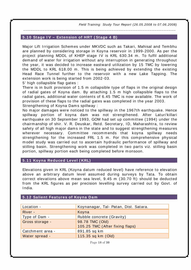
5.10 Stage IV – Extension of HRT (Stage 4 B) Major Lift Irrigation Schemes under MKVDC such as Takari, Mahisal and Tembhu are planned by considering storage in Koyna reservoir in 1999-2000. As per the project planning MDDL of KHEP stage IV is KRL 630.34 m. To fulfil additional demand of water for irrigation without any interruption in generating throughout the year, it was decided to increase eastward utilization by 15 TMC by lowering the MDDL to KRL 618.00 m. This is being achieved by extending the existing Head Race Tunnel further to the reservoir with a new Lake Tapping. The extension work is being started from 2002-03. 5’ high collapsible flap gates : There is in built provision of 1.5 m collapsible type of flaps in the original design of radial gates of Koyna dam. By attaching 1.5 m high collapsible flaps to the radial gates, additional water contents of 6.45 TMC is now available. The work of provision of these flaps to the radial gates was completed in the year 2003. Strengthening of Koyna Dams spillway : No major damages were noticed to the spillway in the 1967th earthquake. Hence spillway portion of koyna dam was not strengthened. After Latur/killari earthquake on 30 September 1993, GOM had set up committee (1994) under the chairmanship of shir. V. R. Deuskar, Retd. Secretary, ID, Maharashtra, to review safety of all high major dams in the state and to suggest strengthening measures wherever necessary. Committee recommends that koyna spillway needs strengthening for the increased FRL 1.5 m. For this comprehensive physical model study was carried out to ascertain hydraulic performance of spillway and stilling basin. Strengthening work was completed in two parts viz. stilling basin portion, spillway portion each being completed before monsoon. 5.11 Koyna Reduced Level (KRL) Elevations given in KRL (Koyna datum reduced level) have reference to elevation above an arbitrary datum level assumed during surveys by Tata. To obtain correct elevations above mean sea level, 9.45 m (30.70 ft) should be deducted from the KRL figures as per precision levelling survey carried out by Govt. of India. 5.12 Salient Features of Koyna Dam Location - Koynanagar, Tal- Patan, Dist. Satara. River - Koyna Type of Dam - Rubble concrete (Gravity) Gross storage - 98.78 TMC (Old)
105.25 TMC (After fixing flaps) Catchment area - 891.85 sq km Water spread - 115.35 sq km (Old)

Field Training: Study Tour Report (26.05.2008 to 07.06.2008) ________________________________________________________________
Page 19 of 30
Max. Ht. above Foundation
103.02 m (NOF) 88.85 m (OF)
Length of Dam - 807.72 m Spillway gates - 6 Nos : Radial
Size – 12.5 x 7.62 m (Flapes – 1.5 m) Dam work - Started – 1954 Completed - 1963 5.13 Salient Features of Kolkewadi Dam Location - Kokewadi, Tal- Chiplun, Dist. Ratnagiri. River - Boladwadi Nalla Purpose - Balancing reservoir Type of Dam - Composite masonry Gross storage - 1.28 TMC Catchment area - 25.40 sq km Water spread - 1.67 sq km Max. Ht. above Foundation 66.30 m Length of Dam - 497 m Spillway gates - 3 Nos : Radial Size – 12.5 x 6.21 m. Dam work - Started – 1966 Completed - 1975 5.14 Stage wise generation STAGE UNITS AND CAPACITY OF
EACH UNIT INSTALLED CAPACITY
YEAR OF COMMENCEMENT
I 4 x 70 280 1962 II 4 x 80 320 1967 III 4 x 80 320 1975 KDPH 2 x 20 40 1982 IV 4 x 250 1000 2000 TOTAL 1960

Field Training: Study Tour Report (26.05.2008 to 07.06.2008) ________________________________________________________________
Page 20 of 30
Chapter 6. Urmodi Project
6.1 Salient Features Sr. No.
Particulars Details
1 Name of Project Urmodi Project
2 Scope of the Scheme Construction of storage reservoir across river Urmodi which is a right tributary of river Krishna to irrigate 7160 ha of land in Satara taluka , 9725 ha in khatav , 9725 ha in Man by flow irrigation and 1140 ha by K.T. weirs.
3 Source Urmodi river right bank tributary of river Krishna
4 Location Near village Parali Tal. Satara,Dist. Satara. i) State Maharashtra ii)Region Western Maharashtra iii) District Satara iv) Taluka Satara 5 Upstream Utilisation Nill
6 Yeild & Utilisation of the Project
i) Catchment area 116.86 Sq. Km. 45.12 Sq. Milies ii) Gross annual utilization 274.678 Mcum 9.700 T.C.M.
7 Dam Reservoir
i) Gross Capacity of Reservoir
282.14 Mcum 9.964 T.C.M.
ii) Capacity of dead storage
8.867 Mcum 0.313 T.C.M.
iii) Capacity of live storage 273.273 Mcum 9.650 T.C.M. iv) Height of dam 50.10 Meter v) Electricity Genration 1.3 MWatt vi) Length of dam( total) 1860 Meter vii) Spillway portion length 57 Meter

Field Training: Study Tour Report (26.05.2008 to 07.06.2008) ________________________________________________________________
Page 21 of 30
1) M.W.L. 696.500 Meter 2) F.R.L. 696.000 Meter 3) M.D.D.L.. 665.650 Meter
4) River bed level 650.560Meter 6.2 Salient Featurs Particulars Details
viii) Area under submergence
1849.08Ha.(approximately)
ix) Type of dam Earthen Dam with gated spillwqy
x) Maximum height of Dam
50.10 Meter
xi) a) No. of villages under submergence
11 Fully & 12 Partially
b) Population affected 5873 Families
Canal R.B.C. satara
L.B.C. satara
Lift I satara
Lift II satara
Khatav Man
a) Full supply discharge in Cumecs
3.985 19.566 1.686 0.925 20.10 9.666
b) Length (Km) 32.00 14.00 28.50 20.00 75.50 31.00
Command Area in Ha. Satara Khatav Man Total
1) G.C.A. 12954 20926 17854 51734
2) C.C.A. 10600 14000 12400 37000

Field Training: Study Tour Report (26.05.2008 to 07.06.2008) ________________________________________________________________
Page 22 of 30
Chapter 7. Nira-Devdhar Project
7.1 Salient Features
Particulars Details
Name of Project Nira Deoghar Project Scope of the Scheme Construction of storage reservoir across river Nira
which is a right tributary of river Bhima to irrigate 43050 …by flow and lift irrigation in Bhor, Khandala, Phaltan & Malshiras Taluka of District Pune. Atara & Solapur.
Source Nira river right bank tributary of river Bhima Location Near village Deoghar Tal. Bhor,Dist. Pune. i) State Maharashtra
ii)Region Western Maharashtra
iii) District Pune
iv) Taluka Bhor
v) Toposheet No. 47 F/12
vi) Latutude 18-6’ 18” North
viii) Longitude 73-43’ -36 East Upstream Utilisation Nill Yeild & Utilisation of the Project i) Catchment area 114.480 Sq. Km. 44.20 Sq. Milies
ii) 50% Dependable yield 367.564 Mcum 12.981 T.C.M.
iii) 75% Dependable yield 320.780 Mcum 11.33 T.C.M.
iv) Gross annual utilization 367.564 Mcum 12.981 T.C.M.
Dam Reservoir i) Gross Capacity of Reservoir 337.390 Mcum 11.911 T.C.M. ii) Capacity of dead storage 5.264 Mcum 0.19 T.C.M.
iii) Capacity of live storage 332.126 Mcum 11.721 T.C.M. iv) Carryover 69.800 Mcum 2.465 T.C.M. v) Annual Utilisation losses 18.40 Mcum 0.65 T.C.M. vi) Controlling R.L.s. of Dam
1) T.B.L.R.L. 670 500 Meter
2) M.W.L.R.L 667.500 Meter
3) F.R.L.R.L. 667.100 Meter
4) M.D.D.L.R.L. 626.000 Meter
Field Training: Study Tour Report (26.05.2008 to 07.06.2008) ________________________________________________________________
Page 23 of 30
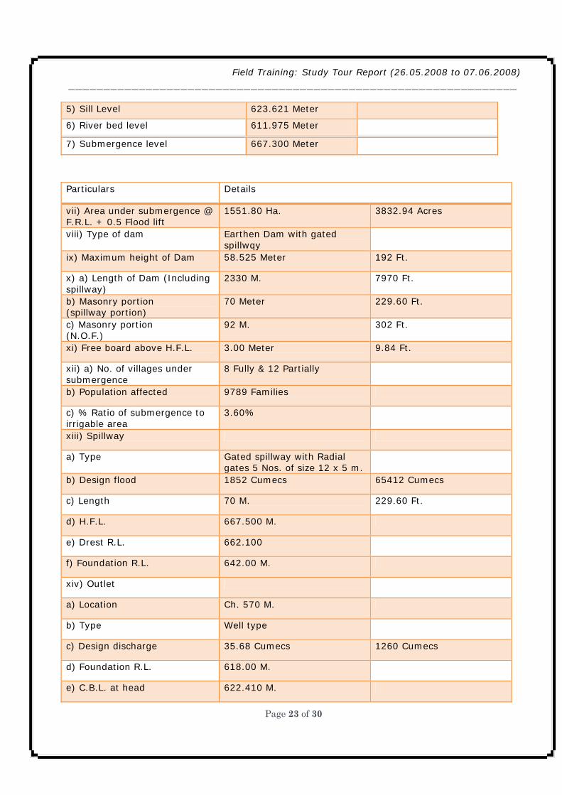
5) Sill Level 623.621 Meter
6) River bed level 611.975 Meter
7) Submergence level 667.300 Meter
Particulars Details
vii) Area under submergence @ F.R.L. + 0.5 Flood lift
1551.80 Ha. 3832.94 Acres
viii) Type of dam Earthen Dam with gated spillwqy
ix) Maximum height of Dam 58.525 Meter 192 Ft.
x) a) Length of Dam (Including spillway)
2330 M. 7970 Ft.
b) Masonry portion (spillway portion)
70 Meter 229.60 Ft.
c) Masonry portion (N.O.F.)
92 M. 302 Ft.
xi) Free board above H.F.L. 3.00 Meter 9.84 Ft.
xii) a) No. of villages under submergence
8 Fully & 12 Partially
b) Population affected 9789 Families
c) % Ratio of submergence to irrigable area
3.60%
xiii) Spillway
a) Type Gated spillway with Radial gates 5 Nos. of size 12 x 5 m.
b) Design flood 1852 Cumecs 65412 Cumecs
c) Length 70 M. 229.60 Ft.
d) H.F.L. 667.500 M.
e) Drest R.L. 662.100
f) Foundation R.L. 642.00 M.
xiv) Outlet
a) Location Ch. 570 M.
b) Type Well type
c) Design discharge 35.68 Cumecs 1260 Cumecs
d) Foundation R.L. 618.00 M.
e) C.B.L. at head 622.410 M.

Field Training: Study Tour Report (26.05.2008 to 07.06.2008) ________________________________________________________________
Page 24 of 30
Canal D.R.B.C. D.L.B.C. Bhor lift Lift I Lift II Lift III
a) Full supply discharge in Cumecs
32.55 0.62 1.53 2.580 2.690 5.600
b) Bed width (in Meter) 7.00 1.80 1.60 2.30 2.50 3.70
c) Free board (Meter) 0.90 0.30 0.60 0.60 0.60 0.60
f) Lining Lined Unlined Lined Lined Lined Lined
g) Length (Km) 208 21 35 30 24 46
Total 364.00
Lift Irrigation Schemes on Right Bank Canal
Bhor Khandala Phaltan
Lift – I Lift – II Lift – III Lift – IV a) Location Venawadi Gavade
wadi Shekhrair wadi
Waghosi Adrki
b) D.R.B.C. Km. 17 37 47 70 - c) C.B.L. of flow canal 617.77 612.85 610.078 604.21 - d) Location stage II on Lift Canal Km.
- - 12 - 24
e) C.B.L. @ Lift Point - - 653.125 652.935 650.425 f) Invert R.L. Stage I Stage II
615.5777 682.200
610.657 -
607.878 651.132
601.513 651.525
648.620 -
g) F.S.L. in Del. Chamber Stage I Stage II
687.000 762.600
687.200 -
656.700 686.600
657.000 686.500
686.600 -
h) Static Head (m) Stage I 71.423 76.543 48.82 55.487 37.98 Stage I - 39.444 34.970 - i) Rising main Length in m
Stage I 430 1635 340 580 - Stage I 1400 - 400 975 550 j) Horse Power Stage I 3500 6300 4500 11900 600 Stage I 1000 - 450 200 - k) Canal Capacity (Comics)
Stage I 1.53 2.58 2.69 5.61 0.45

Field Training: Study Tour Report (26.05.2008 to 07.06.2008) ________________________________________________________________
Page 25 of 30
Stage I 0.42 - 0.34 0.17 - l) Canal Length in (Km)
Stage I 35 30 18 32 8 Stage I - - 6 6 - m) Irrigable area (Ha.)
1640 2580 2710 6390
Acres (ICA) Command Area in Ha. 1) D.C.A. a) Flow DRBC 2600 14300 26920 11278 55098 DLBC 1200 - - - 1200 b) Lift 2280 12645 7020 - 21945 c) Co-operative lift 3677 314 389 7473 11853 Total 9757 27259 34329 18751 90096
Chapter 8 Bhama-Aaskhed Project
8.1 General Information 1) Project Site : At Karanjvihir, Tal: Khed, Dist : Pune 2) River : Bhama River 3) Catchment Area : 198.08 Sq km 4) 50 % dependable yield : 216.83 M cum 5) Gross Storage : 216.388 M cum 6) Live Storage : 208.126 M cum 7) Dead Storage : 8.25 M cum 8) Annual Water Use : 193.112 M cum 8.2 Details of Dam 1) Total Length of Dam : 1425 m 2) Max. Height of Dam : 51m 3) Spillway Type : Ogee Spillway with Radial Gates (4 nos. , size 12m x 5m) 4) Outlet : Irrigation cum Power Outlet at Ch. 660.00 m 5) Submergence Area : 2091 hector.

Field Training: Study Tour Report (26.05.2008 to 07.06.2008) ________________________________________________________________
Page 26 of 30
6) Villages under Submergence : a) Fully Submerged 3 nos. (Parale, Anawale, Waki) : b) Partially Submerged 5 nos (Kasari, Shive, Waghu, Paint, Roudhalwadi) 7) Talukawise I.C.A. : Khed Taluka – 9088 Ha Haveli Taluka – 6587 Ha Daund Taluka – 7435 Ha 8) Canals : Left Bank Canal – Length – 14 Km Capacity – 1.18 Cumec Right Bank Canal – Length – 119 Km Capacity – 15.864 Cumec 9) Power Generation : 2 MW capacity one unit 10) Project Cost (1991-92) : Rs. 11293.43 Lakh 11) B/C Ratio : 2.04 12) Submerged Area/ICA : 9.05 % 13) Control Levels 1) Dam Top Level : 675.600 m 2) M.F.L. : 673.100 m 3) F.R.L. : 671.500 m 4) M.D.D.L. : 644.250 m 5) Spillway Crest Level : 666.500 m 6) River Bed Level : 624.475 m 7) I.C.P.O. Sill level : 641.250 m 8) Earth dam top level : 674.100 m 9) Pitching top level : 675.600 m
Chapter 9 Bhandardara Project
9.1 Salient Features 1) Name Bhandardara, Tal- Akole Dist- Ahmednagar 2) Type Masonry Dam 3) Topo sheet No 47 E 14 4) Latitude 19-32-43 N Longitude 73-45-30 E

Field Training: Study Tour Report (26.05.2008 to 07.06.2008) ________________________________________________________________
Page 27 of 30
5) Height of Dam 82.32 m 6) Length of Dam 507.00 m 7) Top Width of Dam 7.00 m 8) Year of Completion 1926 9) Year of Starting 1910 10) Catchment Area 122.00 Sq. Km 11) Live Storage 312.63 MCM 12) Dead Storage 8.50 MCM 13) Top of Parapet Wall 747.335 m 14) T.B.L. 746.035 m 15) H.F.L. 745.420 m 16) F.R.L. 744.725 m 17) Sill R.L. of 50 feet Outlet 678.980 m 18) Sill R.L. of 100 feet Outlet 694.220 m 19) Sill R.L. of 150 feet Outlet 709.270 m 20) Sill R.L. of 200 feet Outlet 724.700 m 21) Spillway Type 41 Feet x 26 Feet 12.5 m x 7.93 m, 2nos Radial Gates 22) Spillway Open Bar Length 170.00 m 23) Spillway Discharging Capacity A) From Radial Gates 1500 Cumecs B) From Open Bar 2550 Cumecs 24) Spillway Crest R.L. 736.80 m 25) Spillway Gate Top R.L. 744.875 m 26) Spillway W W Bar Top R.L. 745.025 m 27) Length of L.B.C. from Ozar Pick Up Weir 76.80 m 28) Length of R.B.C. from Ozar Pick Up Weir 52.80 m 29) Annual Rainfall (Up Ghat ) 5460 m (On Dam ) 3225 m 30) Area of Submargence 1555.00 Ha 31) Power M.D.D.L. for P.H.I. 720.70 m 32) I.C.A. 23077.00 Ha 33) C.C.A. 63740.00 Ha 34) G.C.A. 80489.00 Ha

Field Training: Study Tour Report (26.05.2008 to 07.06.2008) ________________________________________________________________
Page 28 of 30
Chapter 10 Nilwande Project
10.1 Salient Features Particulars Details Name of Project Uradhava Pravara Project ( Nilwande-II) Scope of the Scheme Construction of storage reservoir across river Pravra
which is a right tributary of river Godawari to irrigate 64260 ha of land in Akole, Sangamner, Rahuri, Shrirampur, Rahta, Kopargao & Sinnar
Location Near village Nilwande Tal. Akole, Dist. Ahmadnagar. i) State Maharashtra ii)Region North Maharashtra iii) District Ahmadnagar iv) Taluka Akole Length of dam( total) 533.00 m Spillway portion length 72.00 m Catchment area 202.21 Sq.Km. Gross Storage 236.00 McM (8.32 TMC) Submergence 802.00 Ha Command Area 64260 Ha Canal R.B.C. L.B.C. a) Command Area Ha. 20395 43865 b) Length (Km) 102.00 85.00

Field Training: Study Tour Report (26.05.2008 to 07.06.2008) ________________________________________________________________
Page 29 of 30
Chapter 11 Conclusion
aharashtra Engineering Training Academy (META), Nashik organized training program for direct recruits - Assistant Executive Engineer & Assistant Engineer (Class I) of Water Resource Department (WRD), in
accordance with Maharashtra Engineering Service Examination-2004. As per schedule of training program, we were directed to undergo Study Tour from 26th May to 08 June 2008. Shri. Pawar saheb was with us during this tour and we visited several projects and we were fortunate to participate in this tour. This report includes the details of projects which we visited during the Study tour.
During the study tour arranged for trainee engineers, I got an opportunity to visit and study gigantic and ambitious Water Resources projects like Sardar Sarovar, Ukai, and Koyna which are internationally recognized. During visit to Prakasha Barrage fabrication work for barrage gates was in progress. Each gate of this barrage is weighing 67 Tons. I studied fabrication, hoisting, installation of barrage gates and construction of deck slab.
During visit to Sardar Sarovar Project, initially the entire basin map of Narmada valley was studied. For the construction of Sardar Sarovar dam the a huge batching plant of 330 cu.m. per hour has been installed and 28 tonne capacity cable was is being operated for sake of construction of dam. This has really added advanced technical background regarding construction of dam. On Narmada main canal, we are fortunate to visit various canal structures like, Chute spillway which is very unique in canal network. We also visited and studied the Rock fill dam in the vicinity of Sardar Sarovar Project.
I visited Surya Dam in Thane district during study tour which is provided with radial spillway gates. It was noticed that these gates are not in operation for several years due to forest clearance problem. This has directly hampered 4 TMC storage capacity of dam achieved by gated storages.
Visit to Koyna Project was really a thrilling experience. In this visit, I came to know the challenging and ambitious work done by our engineers. They have toiled hard for the upliftment to our state. I visited Kolkewadi dam and its power
M

Field Training: Study Tour Report (26.05.2008 to 07.06.2008) ________________________________________________________________
Page 30 of 30
house and related structures which has inspired me to do some challenging work in my career in the department.
During site visit to Nilwande dam we studied colgrout masonry work.
Apart form above projects we visited some completed as well as ongoing projects like Nira-Deodhar, Bhatghar, Bhandardara, Dhom-Balkawadi, Dhom, Bhama Aaskhed, Urmodi etc. Visit to these projects has definitely updated my technical background in this field.