Embed Size (px)
Citation preview

9(2012) 581 – 596
Control of the breathing mechanism of a cracked rotor by usingelectro-magnetic actuator: numerical study
Abstract
This paper presents a numerical study devoted to the eval-
uation of the possibility of monitoring and controlling the
dynamic behavior of a rotating machine with a cracked shaft
by using an Electro-Magnetic Actuator (EMA). The EMA is
located at the mid-span of the rotor to provide active control.
The opening and closure (breathing) of the crack is deter-
mined by the stress field over its cross section resulting from
the dynamic bending moment. The system is nonlinear due
to the fact that the crack parameters must be determined
for each time step and the EMA introduces forces that are
inversely proportional to the square of the gap value be-
tween the stator and the rotor. The model developed takes
into account the behavior of the crack and the influence of
the EMA. Simulations were carried out to access the pos-
sibility of controlling the breathing mechanism. The results
obtained demonstrate the possibility of using the EMA in or-
der to keep the crack closed along the rotation of the rotor,
thus forming a self-healing scheme for the cracked rotor.
Keywords
Rotordynamics, electro-magnetic actuator, cracked rotors,
breathing mechanism, crack control.
Tobias Souza Moraisa,Valder Steffen Jra,∗ andJarir Mahfoudb
aFederal University of Uberlndia, School
of Mechanical Engineering, Campus Santa
Monica, 38400-902, Uberlndia - MG, Brazil.bUniversite de Lyon, CNRS, INSA-Lyon, LaM-
CoS UMR5259, F-69621, France, 69621
Villeurbanne Cedex, France.
Received 22 Mar 2012;In revised form 16 May 2012
∗ Author email: [email protected]
1 INTRODUCTION
The propagation of fatigue cracks may lead to catastrophic failures in rotating machines.
Significant research effort has being developed over the last twenty years aiming at detecting
cracks. More recently, in the context of structural health monitoring and maintenance, the
safe operation of cracked shafts is desired. Then, the machine can work continuously for the
longest possible time, before any intervention for repair. The crack closure phenomenon is
an important variable in fatigue crack propagation and has been extensively studied through
different methods [11, 14, 15]. Usually, in industrial applications the cracked shafts can be kept
under operation for many years, if correctly monitored and operated before being replaced. In
general, when a cracked rotor operates under the load of its own weight, the crack will open
and close once per revolution forming the so-called breathing mechanism. This phenomenon
Latin American Journal of Solids and Structures 9(2012) 581 – 596

582 T.S. Morais et al / Control of the breathing mechanism of a cracked rotor by using electro-magnetic actuator
NOMENCLATURE
x(t) is the generalized displacement vector;
M is the matrix of inertia;
Cb is bearing viscous damping matrix;
Cg is the matrix of the gyroscopic effect with respect to the rotation velocity;
Kg is the matrix of the gyroscopic effect with respect to the acceleration of the
rotor;
∅ is the angular velocity;
K(t) is the stiffness matrix for the system containing the cracked element;
Fu(t) is the unbalance force vector;
FEMA(t) is the force vector related with the Electro-Magnetic Actuator (EMA);
Mx is the dynamic moment with respect with the x-axis;
Mz is the dynamic moment with respect with the z-axis;
I is the second moment of area of the element;
E is the Young’s Modulus;
G is the Shear Modulus;
θx is the rotation with respect to the x-axis;
θz is the rotation with respect to the x-axis;
Lc is the length of the cracked element;
S is the cross section area;
ϕ is the parameter that accounts for the shear effects;
C1 and C2 are constants that depend on the geometric properties of each electro-magnetic
actuator;
e is the air gap value;
δ is the co-localized displacement;
P is the crack position;
Ar is the cross section area of the cracked element;
xj and zj the vibration displacements along the x and z directions, respectively;
np is the number of measures;
t is the time vector.
makes the stiffness matrix of the shaft nonlinear and periodically time varying. In [2] the
authors described a number of difficulties associated to crack identification in shafts supported
by active-magnetic bearings. Quoting these authors, “it is impossible to use the traditional
method with the 2X and 3X revolution super-harmonic frequency components in the super-
critical speed region to detect the crack”. In [9] the authors reported having accomplished the
active health monitoring of rotor-dynamics systems in the presence of cracked shafts performing
the breathing phenomenon. In the two latter references the crack model used did not consider
the breathing behavior of the crack as a function of the dynamical behavior of the structure,
but only as a function of the rotor angular position. The breathing model was introduced
to describe the crack behavior in [5], i.e., the cross coupled stiffness in a simple crack model
Latin American Journal of Solids and Structures 9(2012) 581 – 596

T.S. Morais et al / Control of the breathing mechanism of a cracked rotor by using electro-magnetic actuator 583
with its parameters depending on the sign of the localized coordinate in the crack position
was considered. The abrupt opening and closure of the crack as explained in this reference
cannot completely express the real breathing mechanism. Applied fracture mechanics concepts
considering a localized flexibility due to cracks, resulting in a complete local flexibility matrix
of a cracked shaft, were studied in [4, 12]. An experimental validation for the breathing
behavior considering a shaft instrumented with many strain gages around the crack position
was presented in [1]. Thus, it was possible to verify the stiffness variation along the shaft
rotation and to validate the results by using a crack model. A method through which it
is possible to determine the time varying stiffness due to the crack by using a time-domain
orthogonal function methodology was developed in [10]. In the present paper, the crack model
depends on the dynamic bending moment that acts in the ends of the cracked element. As
the fatigue process in rotating shafts is characterized by the breathing mechanism, this paper
proposes an approach that permits keeping the system operating by slowing down the progress
of the fatigue process. This is achieved by using an Electro-Magnetic Actuator (EMA), which
controls the dynamics of the system so that the total opening of the crack is avoided. To
meet this requirement four actuators are arranged along two perpendicular directions, which
apply attraction forces that produce bending moments to maintain the crack closed. The
electro-magnetic actuator is used to compose a self-healing system in such a way that the
rotor can continue its operation since the increase of the fatigue crack is avoided. The present
contribution is focused on the modeling and simulation of rotating systems with two nonlinear
sources: i) a crack that produces variation in the stiffness as a function of the stress field
over the shaft cross section that depends on the crack’s angular position, and ii) the control
forces applied by the EMA that depend on the shaft displacement. For this aim three sub-
systems are modeled and described in the following: the rotor, the crack, and the actuator.
The present contribution is devoted to applications related to steady state rotating conditions.
The possibility of interfering on the breathing mechanism of the crack may lead to a new
possible use of active magnetic bearings.
2 ROTOR MODEL
The dynamic response of the considered mechanical system can be modeled by using the
Hamilton’s principle. For this aim, the strain energy of the shaft and the kinetic energies of
the discs and shaft are calculated. An extension of Hamilton’s principle makes possible to
include the effect of energy dissipation. The parameters of the bearings are included in the
model by using the principle of the virtual work. For computation purposes, the finite element
method (FEM) is used to model the structure so that the energies calculated are concentrated
at the nodal points. Shape functions are used to connect the nodal points. To obtain the
stiffness of the shaft the Timoshenko’s beam theory was used and the cross sectional area was
updated as proposed in [6]. The model obtained is represented mathematically by a set of
differential equations as given by Equation (1):
Mx(t) + [Cb + ∅Cg] x(t) + [K(t) + ∅Kg]x(t) = Fu(t) +FEMA(t) (1)
Latin American Journal of Solids and Structures 9(2012) 581 – 596

584 T.S. Morais et al / Control of the breathing mechanism of a cracked rotor by using electro-magnetic actuator
where: x(t) is the generalized displacement vector; M, Cb, Cg and Kg are the well known
matrices of inertia, bearing viscous damping, gyroscopic effect with respect to the rotation
velocity ∅ and gyroscopic effect with respect to the acceleration of the rotation ∅, respectively[8]. K is the stiffness matrix for the system containing the cracked element, and Fu(t) andFEMA(t) are forces due to unbalance and Electro-Magnetic Actuator (EMA), respectively.
The system studied is presented in Figure 1. It is composed of a horizontal flexible shaft
of 0.04 m of diameter and two discs represented by D1 and D2. The shaft is supported by
symmetric bearings at its ends: two ball bearings at the left hand end (2 ⋅ 108 N/m stiffness
and 800 Ns/m viscous damping) and a roller bearing at the right hand end (6 ⋅ 106 N/m and
800 Ns/m). The EMA is represented by B2. Its position is chosen by considering the dynamic
behavior of the system (efficiency of the electro-magnetic actuator on the dynamics of the
crack).
Figure 1 Rotor System
A finite element model shown in Figure 2 was used to carry out the numerical simulations.
For this aim, the model contains the following elements: rigid discs with only kinetic energy
contribution, flexible shaft with kinetic and strain energies as represented by Timoshenko
beam elements with two nodes per element and 4 degrees of freedom (d.o.f.) per node. Only
the displacement response generated by using the first eight modes at the EMA position was
considered for all analyses performed.
Figure 2 Rotor Finite Element Model
The simulation was performed by using a computer code that was built on the MATLAB/
SIMULINK® environment. The optimization tools used in the present study were already
previously developed as in [16].
Latin American Journal of Solids and Structures 9(2012) 581 – 596

T.S. Morais et al / Control of the breathing mechanism of a cracked rotor by using electro-magnetic actuator 585
3 CRACK MODEL
The breathing mechanism is a result of the stress and strain distribution around the cracked
area, which is due to static loads (such as the rotor weight), the bearing reaction forces,
and the dynamic loads (such as the unbalance and the vibration induced by the inertia force
distribution). When the static loads overcome the dynamic ones, the breathing is governed
by the angular position of the shaft with respect to the stationary load direction, so that the
crack opens and closes completely once at each revolution. The transition from closed crack
(full stiffness) to open crack (residual stiffness) has been generally considered as being abrupt
[5] or represented by a given cosine function. The corresponding calculation can be carried out
step by step through an iterative procedure as proposed in this paper. The opening and the
closing (breathing) of the crack is determined by the stress field over its cross section as caused
by the dynamic bending moments. The hypothesis of heavy rotor, for which the dynamic
behavior of the crack (opening and closing) is only a function of the rotor angular position, is
discarded in the present contribution. Here, the system is nonlinear and the crack parameters
have to be determined for each time step. The model of the breathing mechanism used in
this paper is based on reference [1]. The breathing mechanism calculation is summarized in
the flowchart shown in Figure 3. The identification process starts with the estimation of the
crack parameters and the modeling of the structure through the finite element method. It is
considered that the crack influences only the stiffness parameters. Consequently, it is assumed
that the other parameters do not change in the presence of a crack. For determining the
stiffness matrix of the cracked element, Kc(t), it is necessary to calculate first the second
moments of inertia of the cross section where the crack is located. For this aim, the cross
section is meshed as shown in Figure 4. Then, the geometric center and the moments with
respect to this point are obtained. The opening and closing of the crack are given as a function
of the stress field resulting from the dynamic efforts and weight of the structure. The tensile
stress should be calculated for each element of the meshed cross section, Figure 4. If the stress
field along the crack is positive, it means that the region is under traction, i.e., the crack is
opened and does not contribute to the calculation of the moments of inertia. Consequently,
a reduction is observed in the values of the elements of the stiffness matrix. On the other
hand, if the field along the crack is negative, the region is under compression, i.e., the crack is
considered closed thus contributing to the moments of inertia of the cross section and to the
corresponding stiffness elements of the stiffness matrix. Due to the cross section asymmetry,
the tensile stress is given by:
σ = (MzIxx +MxIxzIxxIzz − I2xz
)x − (MxIzz +MzIxzIxxIzz − I2xz
) z (2)
The dynamic moments Mx and Mz are given from the strength of materials theory:∂θx∂y= Mx
EIand ∂θz
∂y= Mz
EIwhere θx and θz are the rotations with respect to the axes x and
z, respectively. In practice, ∂θx = θi+1x − θix is considered, where i is the node at the end of
cracked element and θy = Lc, where Lc is the length of this element, as illustrated in Figure 5.
Latin American Journal of Solids and Structures 9(2012) 581 – 596

586 T.S. Morais et al / Control of the breathing mechanism of a cracked rotor by using electro-magnetic actuator
Figure 3 Flowchart for the iterative calculation of the breathing mechanism with the EMA
Figure 4 Cross section of the cracked element
Latin American Journal of Solids and Structures 9(2012) 581 – 596

T.S. Morais et al / Control of the breathing mechanism of a cracked rotor by using electro-magnetic actuator 587
Figure 5 Equivalent cracked beam element
Once the breathing mechanism and the area moments of inertia have been defined, as
previously described, the stiffness matrix of an equivalent cracked beam element of suitable
length, Lc, can be calculated by assuming a Timoshenko’s beam theory. Constant cross section
and constant area moments of area along the length of the element are considered, as shown
in Figure 5. The neighboring beam elements are simply uniform circular cross section beams.
This model is considered a simplified flexible model.
Figure 6 Relationship between the crack relative depth p, the diameter D and the length Lc of “equivalent”beam
It is possible to obtain a three-dimensional model that derives from the nonlinear finite
element technique. In Figure 6 a relation involving both the simplified flexible model and
the 3D model is presented. This relation permits the determination of the optimal length
value of the cracked element that is used to fit the simplified model to the 3D model. The
stiffness matrix (square 8×8 symmetrical matrix ) is represented by Equation (3). More details
regarding the identification of this matrix can be found in [2].
Latin American Journal of Solids and Structures 9(2012) 581 – 596

588 T.S. Morais et al / Control of the breathing mechanism of a cracked rotor by using electro-magnetic actuator
KC(t) =
⎡⎢⎢⎢⎢⎢⎢⎢⎢⎢⎢⎢⎢⎢⎢⎢⎢⎢⎣
b p −q −d −b −b −q −dp a c q −p −a c q
−q c e r q −c f s
−d q r h d −q s g
−b −p q d b p q d
−p −a −c −q p a −c −q−q c f s q −c e e
−d q s g d −q r h
⎤⎥⎥⎥⎥⎥⎥⎥⎥⎥⎥⎥⎥⎥⎥⎥⎥⎥⎦
⎧⎪⎪⎪⎪⎪⎪⎪⎪⎪⎪⎪⎪⎪⎪⎪⎪⎨⎪⎪⎪⎪⎪⎪⎪⎪⎪⎪⎪⎪⎪⎪⎪⎪⎩
xi
zi
θixθizxi+1
zi+1
θi+1x
θi+1z
⎫⎪⎪⎪⎪⎪⎪⎪⎪⎪⎪⎪⎪⎪⎪⎪⎪⎬⎪⎪⎪⎪⎪⎪⎪⎪⎪⎪⎪⎪⎪⎪⎪⎪⎭
(3)
where the coefficients that appear in the matrix above are defined as:
a =12IyyE
(1 + ϕ)L3c
, b = 12IxxE
(1 + ϕ)L3c
, c =6IyyE
(1 + ϕ)L2c
, d = 6IxxE
(1 + ϕ)L2c
,
e =(4 + ϕ)IyyE(1 + ϕ)Lc
, f =(2 − ϕ)IyyE(1 + ϕ)Lc
, g = (2 − ϕ)IxxE(1 + ϕ)Lc
, h = (4 + ϕ)IxxE(1 + ϕ)Lc
,
p =12IxyE
(1 + ϕ)L3c
, q =6IxyE
(1 + ϕ)L2c
, r =(4 + ϕ)IxyE(1 + ϕ)Lc
, s =(2 − ϕ)IxyE(1 + ϕ)Lc
and ϕ = 12EI
GSL2c
The parameter ϕ accounts for the shear effects, E and G are respectively the Young’s
modulus and the shear modulus, S is the cross section area, and I represents the second
moments of area.
4 ACTUATOR MODEL
The Electro-Magnetic Actuator (EMA) used in this paper, Figure 7, consists of 4 electro-
magnetic coils; each one applies an attraction force [3] whose mathematical representation is
shown in Table 1. The forces applied by the electro-magnetic actuators (FEMA) are written
as a function of two constants C1 and C2 that depend on the geometric properties of each
electro-magnetic actuator. Also, these forces are a function of the air gap value (e) and the
co-localized displacement (σ). The values of the coil parameters used in this work are given in
Table 1. These values correspond to a real EMA that is commonly used in experimental work.
The currents used to drive the coils were designed so that they exhibit two terms, namely
a constant current in each coil that is added to a varying current depending on the crack
angular position. The constant form is used to contribute to vibration reduction for some
speeds of rotation; however, constant currents are not necessary for other speeds of rotation
in the operation range of the machine as can be seen in Figure 7. This configuration aims at
producing an attraction force that is sufficiently large to avoid the total opening of the crack
and small enough to avoid a significant increase of the structure displacements. The varying
Latin American Journal of Solids and Structures 9(2012) 581 – 596

T.S. Morais et al / Control of the breathing mechanism of a cracked rotor by using electro-magnetic actuator 589
Table 1 Coil Parameters
µ0 (H/m) µr (H/m) N (spires) a (mm) b (mm) c (mm) d (mm) e (mm)
1.257 ⋅ 10−6 700 278 21 84 63 21 1.5
FEM =µ0fa(NI)2
2 [(e ± δ) + b + c + d − 2aµr
]2
Figure 7 Electric current design for each coil as a function of the angular position of the rotor
Latin American Journal of Solids and Structures 9(2012) 581 – 596

590 T.S. Morais et al / Control of the breathing mechanism of a cracked rotor by using electro-magnetic actuator
currents follow a sinusoidal law, which begin at the time when the point P (crack position)
passes to the opposite side of the coil. These varying currents reach a maximum value when
P is at the most distant position with respect to the coil and are zero when it returns to the
same side of the coil, as shown in Figure 7. This result was obtained for the case in which a
constant current of 0.3 A was used in each coil. For the case in which the rotor performs an
inverse whirl motion the configuration of these currents is such that they keep the crack open,
i.e., their feature is precisely the opposite of the previous one.
5 DESCRIPTION OF THE CRACK CLOSURE APPROACH
The procedure to minimize the crack opening can increase the vibration level of the rotor,
thus leading to undesired side effects. Consequently, the goal of the proposed approach at this
point is to determine a current combination that is capable of minimizing the crack opening
and, at the same time, does not induce either large vibrations or instability to the system.
Consequently, a multi-criteria optimization context is formulated. Various optimization tech-
niques are available to handle the problem. In the present paper, the authors have chosen a
heuristic method, the so-called Particle Swarm Optimization (PSO), to determine the optimal
parameters of the system. The choice of this method is related to its simplicity, easiness of
implementation and the ability of avoiding local minima that may appear in the design space.
It was developed by the social psychologist James Kennedy and the electrical engineer Russel
Eberhart [7], as emerged from experiences with algorithms inspired in the social behavior of
some bird species. PSO is a global optimization technique for dealing with problems in which
the best solution can be represented as a point or surface in an n-dimensional space [13]. The
multi-objective function takes into account simultaneously the following criteria: i) the re-
duction of the crack opening, Equation (4), and ii) the minimization of the system vibration,
Equation (5) and Equation (6), as measured along the x and z directions, respectively, at the
position of the EMA. The design variables considered are the following: four constant currents
and four variable currents for the coils, thus totalizing eight design variables.
F1 =[S(t) −Ar(t)]2
[S(t)]2(4)
F2 =np
∑j=1[xj(t)]2 (5)
F3 =np
∑j=1[zj(t)]2 (6)
where: Ar and S are the cross section areas of the element with and without crack, respec-
tively, and xj and zj are the vibration displacements along the x and z directions for each
measurement point (np), respectively.
Figure 8 shows the variation of the unbalance response, during run-down from 4500 rpm
to rest, for different values of the electric current for the case in which constant currents are
Latin American Journal of Solids and Structures 9(2012) 581 – 596

T.S. Morais et al / Control of the breathing mechanism of a cracked rotor by using electro-magnetic actuator 591
applied to the coils. It can be observed that the vibration amplitude decreases as the current
intensity increases, for determined rotation speed ranges. Also, a shift of the critical speeds
is observed as the current increases. This behavior motivates the use of the constant part
of the current. Besides, when the rotor is mounted horizontally the weight influences the
dynamics of the crack significantly. The constant current minimizes the static deformation
of the rotor. Finally, it is expected that the optimization method is able to find zero current
intensity depending on the given rotation speed; also, different current intensities are supposed
to be found for the rotor either in the horizontal or vertical configurations.
Figure 8 Unbalance Response (run-down) for a non-cracked rotor as a function of the electric current
6 RESULTS AND DISCUSSIONS
Two system configurations are addressed: first, a flexible rotor was mounted in the vertical
position so that the weight does not influence the crack dynamics; second, the same rotor was
mounted horizontally so that the weight becomes an important factor in the dynamics of the
crack. For simulation purposes, the crack depth used was equal to the shaft radius and the
length of the cracked element was determined according to Figure 6. For the optimization
process 120 individuals were considered and 80 iterations were performed. The currents range
from 0 to 5 A, corresponding to values that are commonly found in experimental work.
6.1 Vertical Rotor
The system was simulated considering the gravity force as being equal to zero, i.e., the crack
breathing is given as a function of dynamic efforts of the structure, only. An unbalance
of 80 g ⋅ cm and phase 0o was applied to disc D1. The steady state rotation was fixed to
1500 rpm. The results found by using the optimization method are given as follows: for the
Latin American Journal of Solids and Structures 9(2012) 581 – 596
592 T.S. Morais et al / Control of the breathing mechanism of a cracked rotor by using electro-magnetic actuator
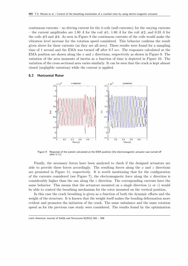
continuous currents – no driving current for the 4 coils (null currents); for the varying currents
– the current amplitudes are 1.80 A for the coil #1, 1.80 A for the coil #2, and 0.33 A for
the coils #3 and #4. As seen in Figure 8 the continuous currents of the coils would make the
vibration level increase for the rotation speed considered. This behavior confirms the result
given above for these currents (as they are all zero). These results were found for a sampling
time of 1 second and the EMA was turned off after 0.7 sec. The responses calculated at the
EMA position are shown along the x and z directions, respectively as shown in Figure 9. The
variation of the area moments of inertia as a function of time is depicted in Figure 10. The
variation of the cross sectional area varies similarly. It can be seen that the crack is kept almost
closed (negligible variation) while the current is applied.
6.2 Horizontal Rotor
Figure 9 Response of the system calculated at the EMA position (the electromagnetic actuator was turned offafter 0.7s)
Finally, the necessary forces have been analyzed to check if the designed actuators are
able to provide these forces accordingly. The resulting forces along the x and z directions
are presented in Figure 11, respectively. It is worth mentioning that for the configuration
of the currents considered (see Figure 7), the electromagnetic force along the x direction is
considerably higher than the one along the z direction. The corresponding currents have the
same behavior. This means that the actuators mounted on a single direction (x or z) would
be able to control the breathing mechanism for the rotor mounted on the vertical position.
In this case the crack breathing is given as a function of both the dynamic efforts and the
weight of the structure. It is known that the weight itself makes the bending deformation more
evident and promotes the initiation of the crack. The same unbalance and the same rotation
speed as for the previous case study were considered. The results found by the optimization
Latin American Journal of Solids and Structures 9(2012) 581 – 596

T.S. Morais et al / Control of the breathing mechanism of a cracked rotor by using electro-magnetic actuator 593
Figure 10 Area moments of inertia of the cross section
Figure 11 Control forces for the breathing mechanism
method for the continuous currents were zero for the coils, except for coil #3, for which it was
found to be 3.11 A. For the varying currents the following amplitude values were obtained:
2.28 A for coil #1, 2.28 A for coil #2, 0.44 A for coil #3, and 0.08 A for coil #4. Similar to the
previous case, the results for the horizontal rotor are displayed along 1 second and the EMA
was turned off after 0.7 sec. In Figure 12 the time responses calculated at the EMA position
are shown along the directions x and z, respectively. The displacements obtained remain
at acceptable values, i.e., the additional energy introduced by the controller does not produce
unaffordable displacements in the system. The variation of the cross sectional area with respect
to time is shown in Figure 13. It can be observed that the crack is kept almost closed while the
actuator is working. The configuration of the rotor corresponding to the horizontal position
Latin American Journal of Solids and Structures 9(2012) 581 – 596

594 T.S. Morais et al / Control of the breathing mechanism of a cracked rotor by using electro-magnetic actuator
characterizes a more difficult control environment as compared to the vertical position, due to
the weight effect.
Figure 12 Response of the system calculated at the EMA position (the electromagnetic actuator was turnedoff after 0.7s)
Figure 13 Cross Section of the cracked element
As in the previous case the resulting control forces could be easily reproduced experi-
mentally (Figure 14). Differently from the vertical rotor, the present configuration requires
control forces along both directions, x and z. The resulting control force along the z direction
corresponds approximately to the weight of the rotor.
Latin American Journal of Solids and Structures 9(2012) 581 – 596

T.S. Morais et al / Control of the breathing mechanism of a cracked rotor by using electro-magnetic actuator 595
Figure 14 Control forces for the breathing mechanism control
7 CONCLUSION
This paper demonstrated the possibility of controlling the fatigue process of a rotating machine
by using electro-magnetic actuators. For the identification of the currents to drive the actuators
validated models for the following sub-systems are required: flexible rotor, crack, and actuator.
Otherwise, it would be necessary to measure the resistant cross section area for different time
instants, which is not possible experimentally. In the case of the vertical rotor, the actuators
mounted on a single direction would be able to control the breathing mechanism. Differently,
the horizontal configuration requires control forces along the directions x and z. For this case,
the resulting control force along the z direction corresponds mainly to the weight of the rotor.
It is expected that the identified currents are able to keep the crack closed when applied to
real systems. The amplitudes of the control forces are plausible from the experimental point
of view. The presented results were obtained for a steady state condition. Next step would be
to observe the transient behavior of the system by using high performance controllers.
Acknowledgments The authors are thankful to the Brazilian research foundations FAPEMIG
and CNPq (Proc. Nb. 574001/2008 − 5; INCT-EIE) for providing financial support to this
work.
References[1] N. Bachschmid, P. Pennacchi, E. Tanzi, and S. Audebert. Transverse crack modeling and validation in rotor systems,
including thermal effects. International Journal of Rotating Machinery, 9(2):113–126, 2003.
[2] Z. Changsheng, D. A. Robb, and D. J. Ewins. The dynamic of a cracked rotor with an active magnetic bearing.Journal of Sound and Vibration, 265(3):469–487, 2003.
[3] J. Der Hagopian and J. Mahfoud. Electromagnetic actuator design for the control of light structures. Smart Structuresand Systems, 6(1):29–38, 2010.
[4] A. D. Dimaragonas and C. A. Papadopoulos. Vibration of cracked shafts in bending. Journal of Sound and Vibration,91(4):583–593, 1983.
Latin American Journal of Solids and Structures 9(2012) 581 – 596

596 T.S. Morais et al / Control of the breathing mechanism of a cracked rotor by using electro-magnetic actuator
[5] R. A Gasch. Survey of the dynamic behaviour of a simple rotating shaft with a transverse crack. Journal of Soundand Vibration, 160(2):313–332, 1993.
[6] J. R. Hutchinson. Shear coefficients for timoshenko beam theory. Journal of Applied Mechanics, 68(1):87–92, 2001.
[7] J. Kennedy and R. C. Eberhart. Particle swarm optimization. In IEEE International Conference on Neural Networks.
[8] M. Lalanne and G. Ferraris. Rotordynamics Prediction in Engineering, Second Edition. John Wiley and Sons, 1998.
[9] G. Mani, D. D. Quinn, and M. Kasarda. Active health monitoring in a rotating cracked shaft using active magneticbearings as force actuators. Journal of Sound and Vibration, 294(3):454–465, 2006.
[10] T. S. Morais, V. Steffen Jr, and N. Bachschmid. Time-varying parameter identification using orthogonal functions.Journal of Physics: Conference Series, 135(1):12072, 2008.
[11] D. Nowell. Techniques for experimental measurement of fatigue crack closure. Applied Mechanics and Materials,7(8):3–9, 2007.
[12] C. A. Papadopoulos and A. D. Dimaragonas. Coupled longitudinal and bending vibration of a rotating shaft withan open crack. Journal of Sound and Vibration, 117(1):81–93, 1987.
[13] P. Pomeroy. An introduction to particle swarm optimization, 2003. Available inhttp://www.adaptiveview.com/articles/ipsoprnt.html.
[14] Y. Pu, J. Chen, J. Zou, and P. Zhong. The research on non-linear characteristics of a cracked rotor and reconstructionof the crack forces. Journal of Mechanical Engineering Science, 216(11):1099–1108, 2002.
[15] S. Stoychev and D. Kujawski. Methods for crack opening load and crack tip shielding determination: A review.Fatigue & Fracture of Engineering Materials & Structures, 2003, Vol. 26, No 11, 26(11):1053–1067, 2003.
[16] F. A. C. Viana. Surrogate Modeling Techniques and Heuristic Optimization Methods Applied to Design and Identi-fication Problems. PhD thesis, Federal University of Uberlndia, Uberlandia, Minas Gerais, Brazil.
Latin American Journal of Solids and Structures 9(2012) 581 – 596