Embed Size (px)
Citation preview
International Journal of Rotating Machinery, 9: 303–311, 2003Copyright c© Taylor & Francis Inc.ISSN: 1023-621XDOI: 10.1080/10236210390147416
Deflections and Strains in Cracked ShaftsDue to Rotating Loads: A Numericaland Experimental Analysis
Nicolo Bachschmid and Ezio TanziDipartimento di Meccanica, Politecnico di Milano, Milan, Italy
In this article the deflections of a circular cross-sectionbeam presenting a transverse crack of varying depths causedby various loads (bending, torsion, shear, and axial loads) areanalyzed with the aid of a rather refined three-dimensionalmodel that takes into account the nonlinear contact forces inthe cracked area. The bending and shear loads are appliedin several different angular positions in order to simulate arotating load on a fixed beam or, by changing the referencesystem, a fixed load on a rotating beam. Torsion and axialloads are fixed with respect to the beam.
Results obtained for the rotating beam can then be usedfor the analysis of cracked horizontal-axis heavy rotors inwhich the torsion is combined with the bending load. Theeffect of friction is also considered in the cracked area. Thecharacteristic “breathing” behavior of the cracked area wasanalyzed and compared to that obtained with a rather simpleone-dimensional model. The differences in results with re-spect to those based on fracture mechanics are emphasized.In order to highlight the effect of the presence of the crack,the deflections of the uncracked beam loaded with the sameloads were subtracted from the deflections of the crackedbeam.
Finally, a cracked specimen was extensively analyzed bymeans of several strain gauges to study the strain distri-bution on the outer surface around the crack in variousloading conditions. Consistent pre-stresses were found, andthey influence the breathing behavior. The experimental
Received 28 March 2002; accepted 28 March 2002.The financial support of MURST cofinanziamento “Identificazione
di malfunzionamenti nei sistemi meccanici” (1999) is gratefullyacknowledged.
Address correspondence to Nicol`o Bachschmid, Dipartimento diMeccanica, Politecnico di Milano, Via la Masa, 34, I-20158 Milano,Italy. E-mail: [email protected]
results were compared with those obtained using the one-dimensional linear model.
Keywords Cracks, Shafts
The behavior of a crack in a rotating shaft can be modeledby various methods, as reported in the literature. In this study,an original simplified linear model that allows cracks of variousshapes to be modeled was used for calculating deflections ofcracked beams in a variety of loading conditions. The resultswere compared with those obtained using two other methods: acumbersome three-dimensional, (3D) nonlinear, finite elementmodel, and a model obtained by using the release rate of the strainenergy as determined by fracture mechanics. The comparisonallowed evaluation of the accuracy of the methods with respectto the 3D model. Finally, experimental results obtained from acracked specimen showed some unexpected effects, which canalso be simulated easily by the simplified model.
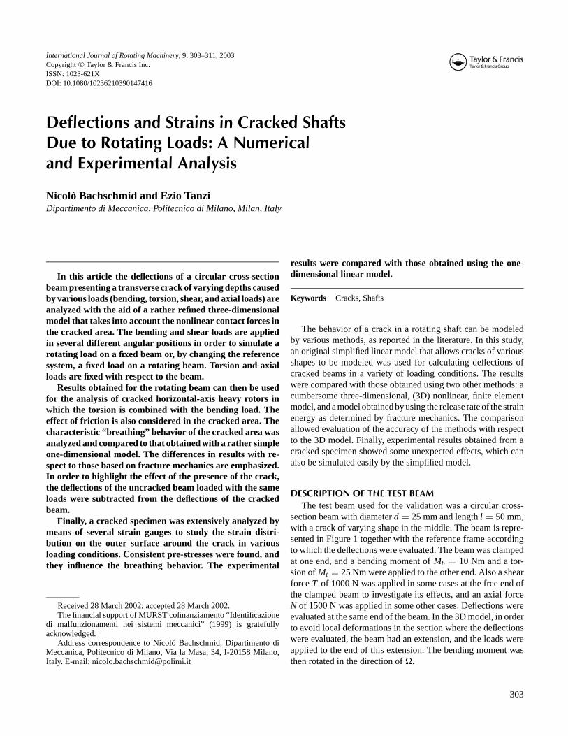
DESCRIPTION OF THE TEST BEAMThe test beam used for the validation was a circular cross-
section beam with diameterd = 25 mm and lengthl = 50 mm,with a crack of varying shape in the middle. The beam is repre-sented in Figure 1 together with the reference frame accordingto which the deflections were evaluated. The beam was clampedat one end, and a bending moment ofMb = 10 Nm and a tor-sion ofMt = 25 Nm were applied to the other end. Also a shearforceT of 1000 N was applied in some cases at the free end ofthe clamped beam to investigate its effects, and an axial forceN of 1500 N was applied in some other cases. Deflections wereevaluated at the same end of the beam. In the 3D model, in orderto avoid local deformations in the section where the deflectionswere evaluated, the beam had an extension, and the loads wereapplied to the end of this extension. The bending moment wasthen rotated in the direction ofÄ.
303
304 N. BACHSCHMID AND E. TANZI
FIGURE 1Test beam.
DESCRIPTION OF THE MODELThe deflections of a test specimen were calculated by means
of three different models: a 3D finite element model, a modelbased on fracture mechanics, and the simplified one-dimensional(1D) model developed by the authors.
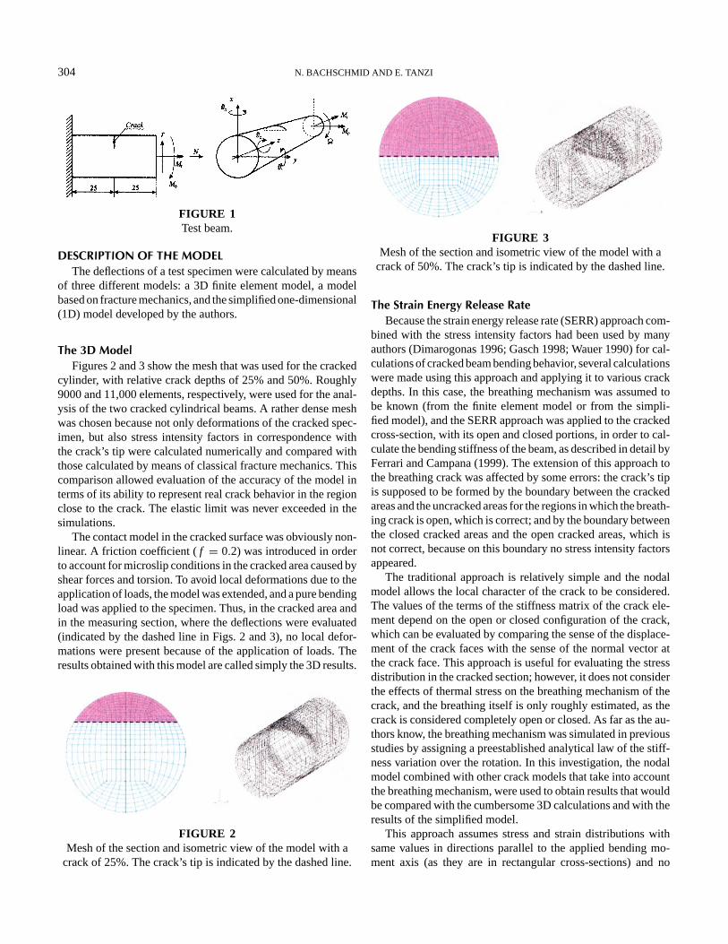
The 3D ModelFigures 2 and 3 show the mesh that was used for the cracked
cylinder, with relative crack depths of 25% and 50%. Roughly9000 and 11,000 elements, respectively, were used for the anal-ysis of the two cracked cylindrical beams. A rather dense meshwas chosen because not only deformations of the cracked spec-imen, but also stress intensity factors in correspondence withthe crack’s tip were calculated numerically and compared withthose calculated by means of classical fracture mechanics. Thiscomparison allowed evaluation of the accuracy of the model interms of its ability to represent real crack behavior in the regionclose to the crack. The elastic limit was never exceeded in thesimulations.
The contact model in the cracked surface was obviously non-linear. A friction coefficient (f = 0.2) was introduced in orderto account for microslip conditions in the cracked area caused byshear forces and torsion. To avoid local deformations due to theapplication of loads, the model was extended, and a pure bendingload was applied to the specimen. Thus, in the cracked area andin the measuring section, where the deflections were evaluated(indicated by the dashed line in Figs. 2 and 3), no local defor-mations were present because of the application of loads. Theresults obtained with this model are called simply the 3D results.
FIGURE 2Mesh of the section and isometric view of the model with a
crack of 25%. The crack’s tip is indicated by the dashed line.
FIGURE 3Mesh of the section and isometric view of the model with a
crack of 50%. The crack’s tip is indicated by the dashed line.
The Strain Energy Release RateBecause the strain energy release rate (SERR) approach com-
bined with the stress intensity factors had been used by manyauthors (Dimarogonas 1996; Gasch 1998; Wauer 1990) for cal-culations of cracked beam bending behavior, several calculationswere made using this approach and applying it to various crackdepths. In this case, the breathing mechanism was assumed tobe known (from the finite element model or from the simpli-fied model), and the SERR approach was applied to the crackedcross-section, with its open and closed portions, in order to cal-culate the bending stiffness of the beam, as described in detail byFerrari and Campana (1999). The extension of this approach tothe breathing crack was affected by some errors: the crack’s tipis supposed to be formed by the boundary between the crackedareas and the uncracked areas for the regions in which the breath-ing crack is open, which is correct; and by the boundary betweenthe closed cracked areas and the open cracked areas, which isnot correct, because on this boundary no stress intensity factorsappeared.
The traditional approach is relatively simple and the nodalmodel allows the local character of the crack to be considered.The values of the terms of the stiffness matrix of the crack ele-ment depend on the open or closed configuration of the crack,which can be evaluated by comparing the sense of the displace-ment of the crack faces with the sense of the normal vector atthe crack face. This approach is useful for evaluating the stressdistribution in the cracked section; however, it does not considerthe effects of thermal stress on the breathing mechanism of thecrack, and the breathing itself is only roughly estimated, as thecrack is considered completely open or closed. As far as the au-thors know, the breathing mechanism was simulated in previousstudies by assigning a preestablished analytical law of the stiff-ness variation over the rotation. In this investigation, the nodalmodel combined with other crack models that take into accountthe breathing mechanism, were used to obtain results that wouldbe compared with the cumbersome 3D calculations and with theresults of the simplified model.
This approach assumes stress and strain distributions withsame values in directions parallel to the applied bending mo-ment axis (as they are in rectangular cross-sections) and no
DEFLECTIONS IN CRACKED SHAFTS 305
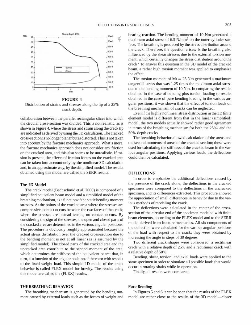
FIGURE 4Distribution of strains and stresses along the tip of a 25%
crack depth.
collaboration between the parallel rectangular slices into whichthe circular cross-section was divided. This is not realistic, as isshown in Figure 4, where the stress and strain along the crack tipare indicated as derived by using the 3D calculation. The crackedcross-section is no longer planar but is distorted. This is not takeninto account by the fracture mechanics approach. What’s more,the fracture mechanics approach does not consider any frictionon the cracked area, and this also seems to be unrealistic. If tor-sion is present, the effects of friction forces on the cracked areacan be taken into account only by the nonlinear 3D calculationand, in an approximate way, by the simplified model. The resultsobtained using this model are called the SERR results.
The 1D ModelThe crack model (Bachschmid et al. 2000) is composed of a
simplified equivalent beam model and a simplified model of thebreathing mechanism, as a function of the static bending momentstresses. At the points of the cracked area where the stresses arecompressive, contact occurs between the two faces of the crack;where the stresses are instead tensile, no contact occurs. Byconsidering the sign of the stresses, the open and closed parts ofthe cracked area are determined in the various angular positions.The procedure is obviously roughly approximated because theactual stress distribution over the cracked cross-section due tothe bending moment is not at all linear (as is assumed by thesimplified model). The closed parts of the cracked area and theuncracked area contribute to the second moment of the area,which determines the stiffness of the equivalent beam; that, inturn, is a function of the angular position of the rotor with respectto the fixed weight load. This simple 1D model of the crackbehavior is called FLEX model for brevity. The results usingthis model are called the (FLEX) results.
THE BREATHING BEHAVIORThe breathing mechanism is generated by the bending mo-
ment caused by external loads such as the forces of weight and
bearing reaction. The bending moment of 10 Nm generated amaximum axial stress of 6.5 N/mm2 on the outer cylinder sur-face. The breathing is produced by the stress distribution aroundthe crack. Therefore, the question arises: Is the breathing alsoinfluenced by the shear stresses due to the external torsion mo-ment, which certainly changes the stress distribution around thecrack? To answer this question in the 3D model of the crackedbeam, a rather high torsion moment was applied to emphasizethe effect.
The torsion moment of Mt= 25 Nm generated a maximumtangential stress that was 1.25 times the maximum axial stressdue to the bending moment of 10 Nm. In comparing the resultsobtained in the case of bending plus torsion loading to resultsobtained in the case of pure bending loading in the various an-gular positions, it was shown that the effect of torsion loads onthe breathing mechanism of cracks can be neglected.
Even if the highly nonlinear stress distribution in the 3D finiteelement model is different from that in the linear (simplified)model, the two models actually showed rather good agreementin terms of the breathing mechanism for both the 25%- and the50%-depth cracks.
The breathing behavior allowed calculation of the areas andthe second moments of areas of the cracked section; these wereused for calculating the stiffness of the cracked beam in the var-ious angular positions. Applying various loads, the deflectionscould then be calculated.
DEFLECTIONSIn order to emphasize the additional deflections caused by
the presence of the crack alone, the deflections in the crackedspecimen were compared to the deflections in the uncrackedspecimen, and its differences extracted. This procedure allowedfor appreciation of small differences in behavior due to the var-ious methods of modeling the crack.
The deflections were calculated in the center of the cross-section of the circular end of the specimen modeled with finitebeam elements, according to the FLEX model and to the SERRmodel derived from fracture mechanics. All six components ofthe deflection were calculated for the various angular positionsof the load with respect to the crack; they were obtained byincreasing the angle in steps of 30 degrees.
Two different crack shapes were considered: a rectilinearcrack with a relative depth of 25% and a rectilinear crack witha relative depth of 50%.
Bending, shear, torsion, and axial loads were applied to thesame specimen in order to simulate all possible loads that wouldoccur in rotating shafts while in operation.
Finally, all results were compared.
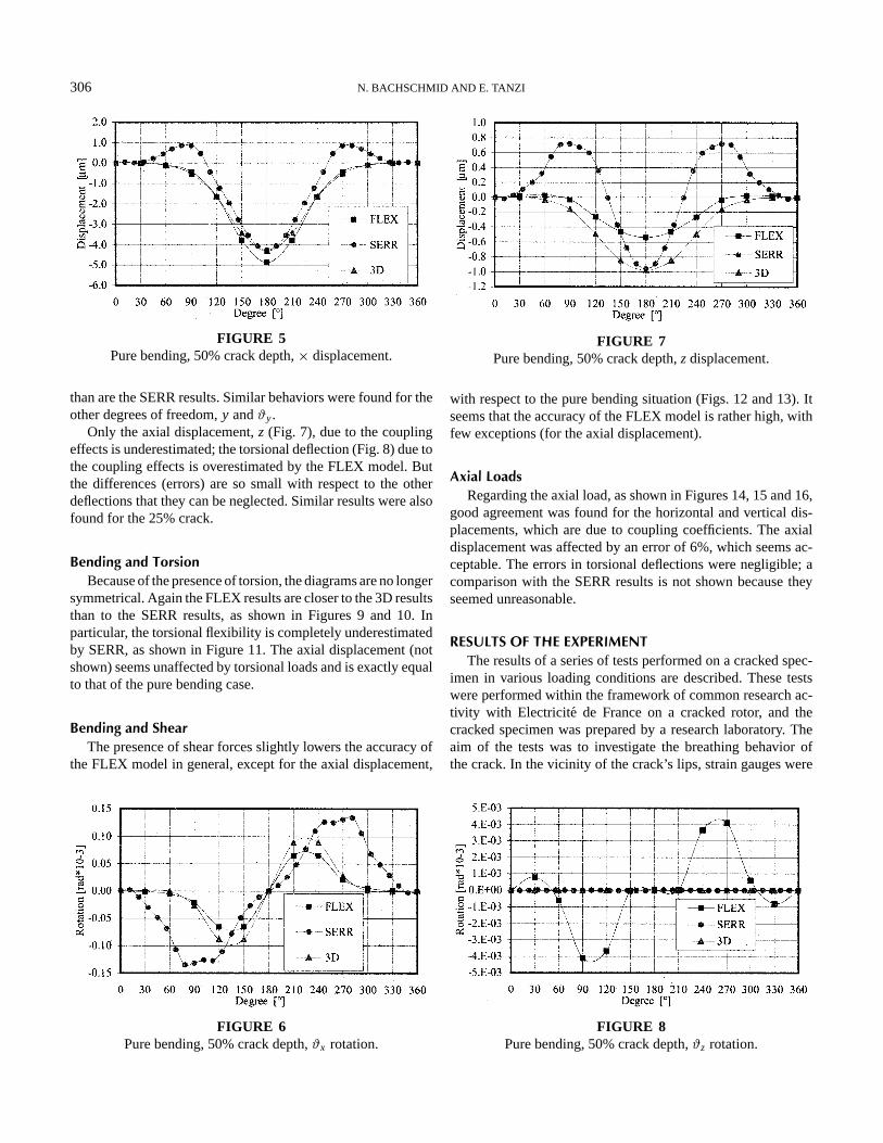
Pure BendingIn Figures 5 and 6 it can be seen that the results of the FLEX
model are rather close to the results of the 3D model—closer
306 N. BACHSCHMID AND E. TANZI
FIGURE 5Pure bending, 50% crack depth,× displacement.
than are the SERR results. Similar behaviors were found for theother degrees of freedom,y andϑy.
Only the axial displacement,z (Fig. 7), due to the couplingeffects is underestimated; the torsional deflection (Fig. 8) due tothe coupling effects is overestimated by the FLEX model. Butthe differences (errors) are so small with respect to the otherdeflections that they can be neglected. Similar results were alsofound for the 25% crack.
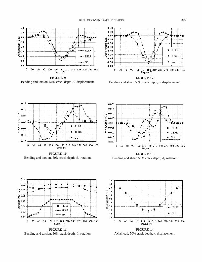
Bending and TorsionBecause of the presence of torsion, the diagrams are no longer
symmetrical. Again the FLEX results are closer to the 3D resultsthan to the SERR results, as shown in Figures 9 and 10. Inparticular, the torsional flexibility is completely underestimatedby SERR, as shown in Figure 11. The axial displacement (notshown) seems unaffected by torsional loads and is exactly equalto that of the pure bending case.
Bending and ShearThe presence of shear forces slightly lowers the accuracy of
the FLEX model in general, except for the axial displacement,
FIGURE 6Pure bending, 50% crack depth,ϑx rotation.
FIGURE 7Pure bending, 50% crack depth,z displacement.
with respect to the pure bending situation (Figs. 12 and 13). Itseems that the accuracy of the FLEX model is rather high, withfew exceptions (for the axial displacement).
Axial LoadsRegarding the axial load, as shown in Figures 14, 15 and 16,
good agreement was found for the horizontal and vertical dis-placements, which are due to coupling coefficients. The axialdisplacement was affected by an error of 6%, which seems ac-ceptable. The errors in torsional deflections were negligible; acomparison with the SERR results is not shown because theyseemed unreasonable.
RESULTS OF THE EXPERIMENTThe results of a series of tests performed on a cracked spec-
imen in various loading conditions are described. These testswere performed within the framework of common research ac-tivity with Electricite de France on a cracked rotor, and thecracked specimen was prepared by a research laboratory. Theaim of the tests was to investigate the breathing behavior ofthe crack. In the vicinity of the crack’s lips, strain gauges were
FIGURE 8Pure bending, 50% crack depth,ϑz rotation.
DEFLECTIONS IN CRACKED SHAFTS 307
FIGURE 9Bending and torsion, 50% crack depth,× displacement.
FIGURE 10Bending and torsion, 50% crack depth,ϑx rotation.
FIGURE 11Bending and torsion, 50% crack depth,ϑz rotation.
FIGURE 12Bending and shear, 50% crack depth,× displacement.
FIGURE 13Bending and shear, 50% crack depth,ϑx rotation.
FIGURE 14Axial load, 50% crack depth,× displacement.
308 N. BACHSCHMID AND E. TANZI
FIGURE 15Axial load, 50% crack depth,ϑx rotation.
applied in order to measure the stresses and to identify the loadconditions (the value of the bending moment and the angularposition of the load with respect to the crack) in which the lipsstart to lose contact. Then the measured stresses were comparedto the stresses that had been calculated using the simplified 1Dmodel.
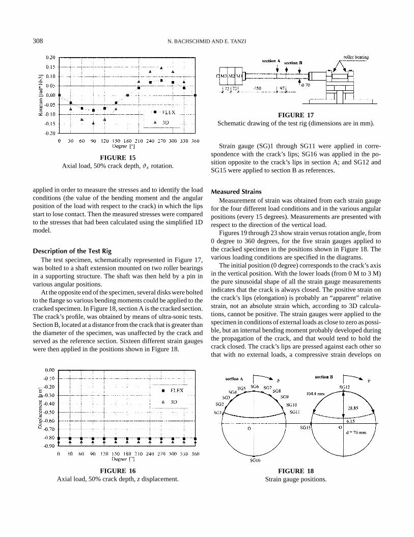
Description of the Test RigThe test specimen, schematically represented in Figure 17,
was bolted to a shaft extension mounted on two roller bearingsin a supporting structure. The shaft was then held by a pin invarious angular positions.
At the opposite end of the specimen, several disks were boltedto the flange so various bending moments could be applied to thecracked specimen. In Figure 18, section A is the cracked section.The crack’s profile, was obtained by means of ultra-sonic tests.Section B, located at a distance from the crack that is greater thanthe diameter of the specimen, was unaffected by the crack andserved as the reference section. Sixteen different strain gaugeswere then applied in the positions shown in Figure 18.
FIGURE 16Axial load, 50% crack depth,z displacement.
FIGURE 17Schematic drawing of the test rig (dimensions are in mm).
Strain gauge (SG)1 through SG11 were applied in corre-spondence with the crack’s lips; SG16 was applied in the po-sition opposite to the crack’s lips in section A; and SG12 andSG15 were applied to section B as references.
Measured StrainsMeasurement of strain was obtained from each strain gauge
for the four different load conditions and in the various angularpositions (every 15 degrees). Measurements are presented withrespect to the direction of the vertical load.
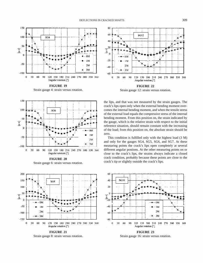
Figures 19 through 23 show strain versus rotation angle, from0 degree to 360 degrees, for the five strain gauges applied tothe cracked specimen in the positions shown in Figure 18. Thevarious loading conditions are specified in the diagrams.
The initial position (0 degree) corresponds to the crack’s axisin the vertical position. With the lower loads (from 0 M to 3 M)the pure sinusoidal shape of all the strain gauge measurementsindicates that the crack is always closed. The positive strain onthe crack’s lips (elongation) is probably an “apparent” relativestrain, not an absolute strain which, according to 3D calcula-tions, cannot be positive. The strain gauges were applied to thespecimen in conditions of external loads as close to zero as possi-ble, but an internal bending moment probably developed duringthe propagation of the crack, and that would tend to hold thecrack closed. The crack’s lips are pressed against each other sothat with no external loads, a compressive strain develops on
FIGURE 18Strain gauge positions.
DEFLECTIONS IN CRACKED SHAFTS 309
FIGURE 19Strain gauge 4: strain versus rotation.
FIGURE 20Strain gauge 6: strain versus rotation.
FIGURE 21Strain gauge 8: strain versus rotation.
FIGURE 22Strain gauge 12: strain versus rotation.
the lips, and that was not measured by the strain gauges. Thecrack’s lips open only when the external bending moment over-comes the internal bending moment, and when the tensile stressof the external load equals the compressive stress of the internalbending moment. From this position on, the strain indicated bythe gauge, which is the relative strain with respect to the initialreference situation, should remain constant with the increasingof the load; from this position on, the absolute strain should bezero.
This condition is fulfilled only with the highest load (3 M)and only for the gauges SG4, SG5, SG6, and SG7. At thesemeasuring points the crack’s lips open completely at severaldifferent angular postions. At the other measuring points on orclose to the crack’s lips, the strains always indicate a closedcrack condition, probably because these points are close to thecrack’s tip or slightly outside the crack’s lips.
FIGURE 23Strain gauge 16: strain versus rotation.
310 N. BACHSCHMID AND E. TANZI
TABLE 1Loads, Bending Moments and Theoretical Strains
Section A Section B
Bending Bendingmoments σ ε moments σ ε
Loads (Nm) (MPa) (µε) (Nm) (MPa) (µε)
0 M 37.4 1.1 5.4 53.0 1.6 7.61 M 104.4 3.1 15.1 134.8 4.0 19.42 M 181.9 5.4 26.2 226.4 6.7 32.63 M 270.7 8.0 39.0 329.7 9.7 47.5
Loads: 0 M, no additional mass; 1 M, 1 additional mass; 2 M, 2additional masses; 3 M, 3 additional masses.
Another interesting point is made by these diagrams. Thevariation in theoretical strain with maximum load, as shown inTable 1, is roughly between+40 and−40 microstrains, in corre-spondence with Section A, and the total peak-to-peak variationis 80 microstrains. In measuring point SG16 there is a minimumof 55 microstrains in the position where the crack is open (thestress distribution is apparently non linear) and there is a maxi-mum of 40 microstrains in the position where the crack is closed(and the stress distribution is linear). This last value is exactlythe theoretical value.
In SG11, a total variation of 88 microstrains indicates nononlinear effects; the crack does not open and in this positionno stress concentration occurs.
In SG1, a total variation of 130 microstrains indicates incom-ing nonlinear effects that increase by moving toward the crack’saxis on both sides.
In SG10 and SG2, 150 peak-to-peak variations in micro-strains are measured; in SG3, 180; and in SG8 and SG9, 250. InSG4 and SG5, the positive peak is flattened because the crack isopening; the minimum is−75 microstrains. Similar behavior isfound at SG6 and SG7, where a minimum of−90 microstrainsis reached.
The consistent increase in strain with respect to the theoreti-cal values can be attributed to local stress concentration, whichobviously depends on the varying depths of the lip’s contactareas in correspondence with the various positions.
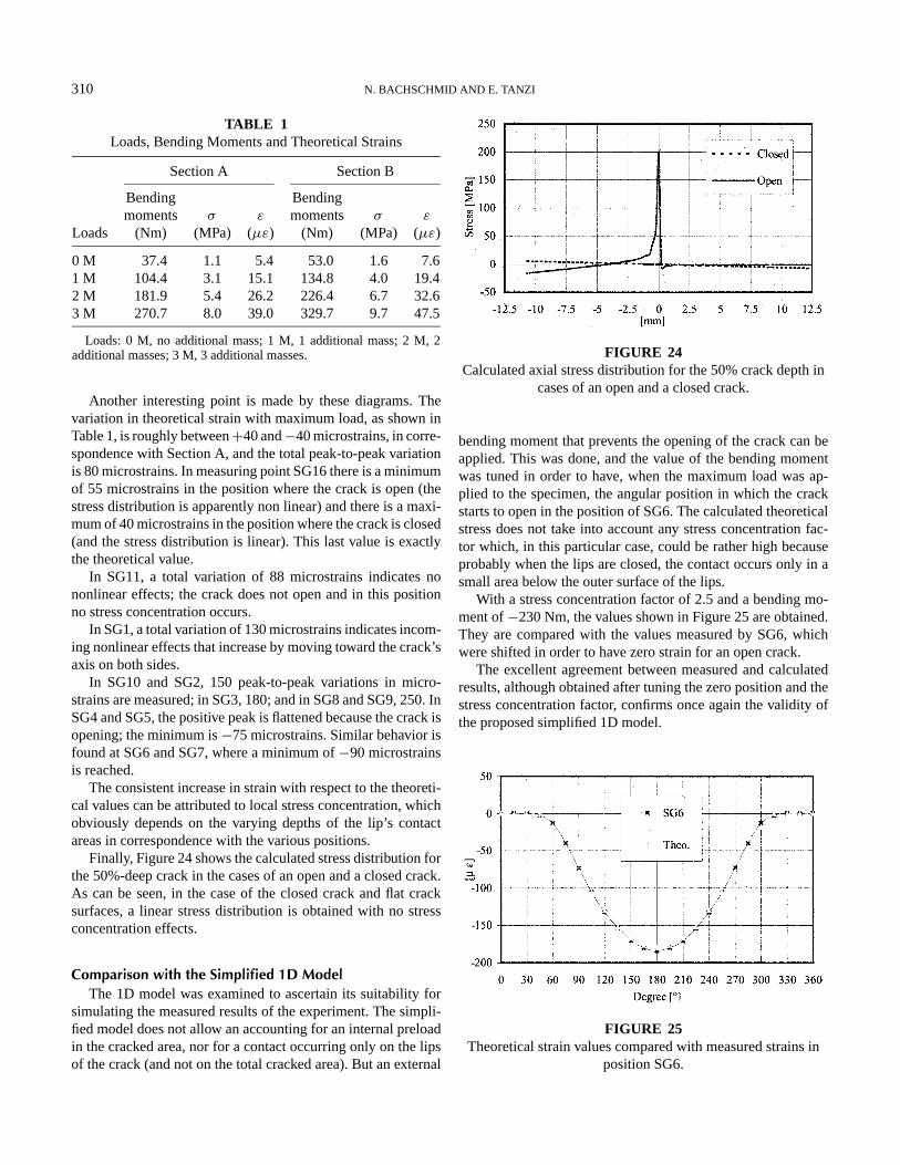
Finally, Figure 24 shows the calculated stress distribution forthe 50%-deep crack in the cases of an open and a closed crack.As can be seen, in the case of the closed crack and flat cracksurfaces, a linear stress distribution is obtained with no stressconcentration effects.
Comparison with the Simplified 1D ModelThe 1D model was examined to ascertain its suitability for
simulating the measured results of the experiment. The simpli-fied model does not allow an accounting for an internal preloadin the cracked area, nor for a contact occurring only on the lipsof the crack (and not on the total cracked area). But an external
FIGURE 24Calculated axial stress distribution for the 50% crack depth in
cases of an open and a closed crack.
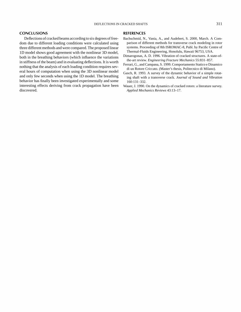
bending moment that prevents the opening of the crack can beapplied. This was done, and the value of the bending momentwas tuned in order to have, when the maximum load was ap-plied to the specimen, the angular position in which the crackstarts to open in the position of SG6. The calculated theoreticalstress does not take into account any stress concentration fac-tor which, in this particular case, could be rather high becauseprobably when the lips are closed, the contact occurs only in asmall area below the outer surface of the lips.
With a stress concentration factor of 2.5 and a bending mo-ment of−230 Nm, the values shown in Figure 25 are obtained.They are compared with the values measured by SG6, whichwere shifted in order to have zero strain for an open crack.
The excellent agreement between measured and calculatedresults, although obtained after tuning the zero position and thestress concentration factor, confirms once again the validity ofthe proposed simplified 1D model.
FIGURE 25Theoretical strain values compared with measured strains in
position SG6.
DEFLECTIONS IN CRACKED SHAFTS 311
CONCLUSIONSDeflections of cracked beams according to six degrees of free-
dom due to different loading conditions were calculated usingthree different methods and were compared. The proposed linear1D model shows good agreement with the nonlinear 3D model,both in the breathing behaviors (which influence the variationsin stiffness of the beam) and in evaluating deflections. It is worthnothing that the analysis of each loading condition requires sev-eral hours of computation when using the 3D nonlinear modeland only few seconds when using the 1D model. The breathingbehavior has finally been investigated experimentally and someinteresting effects deriving from crack propagation have beendiscovered.
REFERENCESBachschmid, N., Vania, A., and Audebert, S. 2000, March. A Com-
parison of different methods for transverse crack modeling in rotorsystems. Proceeding of 8th ISROMAC-8, Publ. by Pacific Centre ofThermal-Fluids Engineering, Honolulu, Hawaii 96753, USA.
Dimarogonas, A. D. 1996. Vibration of cracked structures. A state-of-the-art review.Engineering Fracture Mechanics55:831–857.
Ferrari, G., and Campana, S. 1999. Comportamento Statico e Dinamicodi un Rotore Criccato. (Master’s thesis, Politecnico di Milano).
Gasch, R. 1993. A survey of the dynamic behavior of a simple rotat-ing shaft with a transverse crack.Journal of Sound and Vibration160:131–332.
Wauer, J. 1990. On the dynamics of cracked rotors: a literature survey.Applied Mechanics Reviews43:13–17.

International Journal of
AerospaceEngineeringHindawi Publishing Corporationhttp://www.hindawi.com Volume 2010
RoboticsJournal of
Hindawi Publishing Corporationhttp://www.hindawi.com Volume 2014
Hindawi Publishing Corporationhttp://www.hindawi.com Volume 2014
Active and Passive Electronic Components
Control Scienceand Engineering
Journal of
Hindawi Publishing Corporationhttp://www.hindawi.com Volume 2014
International Journal of
RotatingMachinery
Hindawi Publishing Corporationhttp://www.hindawi.com Volume 2014
Hindawi Publishing Corporation http://www.hindawi.com
Journal ofEngineeringVolume 2014
Submit your manuscripts athttp://www.hindawi.com
VLSI Design
Hindawi Publishing Corporationhttp://www.hindawi.com Volume 2014
Hindawi Publishing Corporationhttp://www.hindawi.com Volume 2014
Shock and Vibration
Hindawi Publishing Corporationhttp://www.hindawi.com Volume 2014
Civil EngineeringAdvances in
Acoustics and VibrationAdvances in
Hindawi Publishing Corporationhttp://www.hindawi.com Volume 2014
Hindawi Publishing Corporationhttp://www.hindawi.com Volume 2014
Electrical and Computer Engineering
Journal of
Advances inOptoElectronics
Hindawi Publishing Corporation http://www.hindawi.com
Volume 2014
The Scientific World JournalHindawi Publishing Corporation http://www.hindawi.com Volume 2014
SensorsJournal of
Hindawi Publishing Corporationhttp://www.hindawi.com Volume 2014
Modelling & Simulation in EngineeringHindawi Publishing Corporation http://www.hindawi.com Volume 2014
Hindawi Publishing Corporationhttp://www.hindawi.com Volume 2014
Chemical EngineeringInternational Journal of Antennas and
Propagation
International Journal of
Hindawi Publishing Corporationhttp://www.hindawi.com Volume 2014
Hindawi Publishing Corporationhttp://www.hindawi.com Volume 2014
Navigation and Observation
International Journal of
Hindawi Publishing Corporationhttp://www.hindawi.com Volume 2014
DistributedSensor Networks
International Journal of