Embed Size (px)
Citation preview
HAL Id hal-03017285httpshalarchives-ouvertesfrhal-03017285v2
Submitted on 15 Jul 2021
HAL is a multi-disciplinary open accessarchive for the deposit and dissemination of sci-entific research documents whether they are pub-lished or not The documents may come fromteaching and research institutions in France orabroad or from public or private research centers
Lrsquoarchive ouverte pluridisciplinaire HAL estdestineacutee au deacutepocirct et agrave la diffusion de documentsscientifiques de niveau recherche publieacutes ou noneacutemanant des eacutetablissements drsquoenseignement et derecherche franccedilais ou eacutetrangers des laboratoirespublics ou priveacutes
Continuous Severe Plastic Deformation of Low-CarbonSteel Physical-Mechanical Properties and Multi-Scale
Structure AnalysisAnatoliy Zavdoveev Thierry Baudin Elena Pashinska Hyoung Seop Kim
Francois Brisset Mark Heaton Valeriy Poznyakov Massimo Rogante ViktorTkachenko Ilya Klochkov et al
To cite this versionAnatoliy Zavdoveev Thierry Baudin Elena Pashinska Hyoung Seop Kim Francois Brisset etal Continuous Severe Plastic Deformation of Low-Carbon Steel Physical-Mechanical Propertiesand Multi-Scale Structure Analysis Steel Research International Wiley 2021 92 (3) pp2000482101002srin202000482 hal-03017285v2
This article has been accepted for publication and undergone full peer review but has not been through the copyediting typesetting pagination and proofreading process which may lead to differences between this version and the Version of Record Please cite this article as doi 101002srin202000482
This article is protected by copyright All rights reserved
Continuous severe plastic deformation of low-carbon steel physical-mechanical properties and multi-scale structure analysis
A Zavdoveev1 T Baudin2 E Pashinska3 HS Kim4 F Brisset2 M Heaton5
V Poznyakov1 M Rogante6 V Tkachenko3 I Klochkov1 M Skoryk7
1 Paton Electric Welding Institute of NAS of Ukraine Bozhenko n 11 03680 Kiev Ukraine avzavdoveevgmailcom
2Universiteacute Paris-Saclay CNRS Institut de chimie moleacuteculaire et des mateacuteriaux dOrsay 91405 Orsay France thierrybaudinuniversite-paris-saclayfr
3 Donetsk Institute for Physics and Engineering named after AA Galkin of the NAS of Ukraine Prospect
Nauky 46 Kyiv Ukraine 03028 4 Pohang University of Science and Technology Department of Materials Science and Engineering
(POSTECH) Pohang 37673 Korea hskimpostechackr 5 ANT Advanced Nano Technology Nandor Rd Park West business park Dublin
markheatonantsltdcom 6 Rogante Engineering Office Contrada San Michele n61 62012 Civitanova Marche Italy
mainroganteengineeringit 7 G V Kurdyumov Institute of Metal Physics of the NAS of Ukraine Kyiv Ukraine mykolaskorgmailcom
Abstract
A successful attempt to incorporate the advantages of severe plastic deformation (SPD) methods in
the continuous drawing process for low-carbon steel is demonstrated The structural features are considered
on different scale levels using a wide range of methods While combining shear deformation which parallels
the basis of SPD with the conventional scheme the cyclic process of grain refinement could be reached As
a result the plasticity becomes enhanced At the same time an important characteristic such as residual
stress also has a positive influence on manufacturability particularly the existence of the compression stress
after shear deformation The peculiarity of the structure affects the behavior of both mechanical and physical
properties (like density plasticity) The application of drawing with shear (DSh) technology as based on SPD
principles the mechanical softening effect is observed as is the healing of micro-voids Such positive
affection gives the opportunity to increase the effectiveness of drawing technology through controlling
plasticity (ductility) Additionally it is considered exhaustion of the plasticity resource (EPR) It is shown that
in the case of multi pass deformation there is a parabolic dependence of the EPR measurement and
minimum damage is achieved using a specific combination of partial reductions
Keywords continuous severe plastic deformation drawing low-carbon steel structure properties
Acc
epte
d A
rticl
ePaton Electric Welding Institute of NAS
Acc
epte
d A
rticl
ePaton Electric Welding Institute of NAS
Universiteacute Paris
Acc
epte
d A
rticl
eUniversiteacute Paris-
Acc
epte
d A
rticl
e-Saclay CNRS Institut de chimie
Acc
epte
d A
rticl
eSaclay CNRS Institut de chimie
Donetsk Institute for Physics and Engineering named after AA Galkin of the NAS of Ukraine Prospect
Acc
epte
d A
rticl
eDonetsk Institute for Physics and Engineering named after AA Galkin of the NAS of Ukraine Prospect
Pohang University of Science and Technology Department of Materials Science and Engineering
Acc
epte
d A
rticl
e
Pohang University of Science and Technology Department of Materials Science and Engineering
5
Acc
epte
d A
rticl
e
5 ANT Advanced Nano Technology Nandor Rd Park West business park Dublin
Acc
epte
d A
rticl
e
ANT Advanced Nano Technology Nandor Rd Park West business park Dublin
Rogante
Acc
epte
d A
rticl
e
Rogante Engineering Office Contrada San Michele n61 62012 Civitanova Marche Italy
Acc
epte
d A
rticl
e
Engineering Office Contrada San Michele n61 62012 Civitanova Marche Italy
G V Kurdyumov Institute of Metal Physics of the NAS of Ukraine Kyiv Ukraine mykolaskorgmailcom
Acc
epte
d A
rticl
e
G V Kurdyumov Institute of Metal Physics of the NAS of Ukraine Kyiv Ukraine mykolaskorgmailcom
A successful attempt to incorporate
Acc
epte
d A
rticl
e
A successful attempt to incorporate
the continuous drawing process for low
Acc
epte
d A
rticl
e
the continuous drawing process for low
on different scale levels using a wide range of methods While combining shear deform
Acc
epte
d A
rticl
e
on different scale levels using a wide range of methods While combining shear deform
the basis of SPD with the conventional scheme the cyclic process of grain refinement could be reached As
Acc
epte
d A
rticl
e
the basis of SPD with the conventional scheme the cyclic process of grain refinement could be reached As
a result the plasticity becomes enhanced At the same time an important characteristic such as residual
Acc
epte
d A
rticl
e
a result the plasticity becomes enhanced At the same time an important characteristic such as residual
Acc
epte
d A
rticl
e
stress also has a po
Acc
epte
d A
rticl
e
stress also has a positive influence on manufacturability particularly the existence of the compression stress
Acc
epte
d A
rticl
e
sitive influence on manufacturability particularly the existence of the compression stress
after shear deformation The peculiarity of the structure affects the behavior of both mechanical and physical
Acc
epte
d A
rticl
e
after shear deformation The peculiarity of the structure affects the behavior of both mechanical and physical
properties (like density
Acc
epte
d A
rticl
e
properties (like density plasticity
Acc
epte
d A
rticl
e
plasticity
principles the mechanical softening effect is observed as is the healing of micro
Acc
epte
d A
rticl
e
principles the mechanical softening effect is observed as is the healing of micro
affection gives the opportunity to increase the effectiveness of drawing technology
Acc
epte
d A
rticl
e
affection gives the opportunity to increase the effectiveness of drawing technology
plasticity (ductility) Additionally it is considered exhaustion of the plasticity resource (EPR) It is shown that Acc
epte
d A
rticl
e
plasticity (ductility) Additionally it is considered exhaustion of the plasticity resource (EPR) It is shown that Acc
epte
d A
rticl
e
in the case of multi pass deformation there is a parabolic dependence of the EPR measurement and Acc
epte
d A
rticl
e
in the case of multi pass deformation there is a parabolic dependence of the EPR measurement and
minimum damage is aAcc
epte
d A
rticl
e
minimum damage is achieved using a specific combination of partial reductions Acc
epte
d A
rticl
e
chieved using a specific combination of partial reductions
2 This article is protected by copyright All rights reserved
1 Introduction
Drawing is one of the most widespread methods of metal forming processes [1ndash3]
and welding wire is used in lots of construction and production processes Thus the
technology of wire manufacturing is very important Notably partial reduction [4] during
wire drawing in the mean of exhausting of plasticity resources is essential Good optimal
reduction choice is a very important step in developing the effective manufacturing
technology of drawing When the plasticity resource is exhausted during the drawing
process [4] the wire starts breaking and the whole process is stopped Then additional
softening annealing is needed The main aim of this procedure is to heal microvoids and
eliminate strain hardening However this is a very expensive procedure In addition there
is a need to enhance the performance characteristics of drawn steel for a minimum
number of intermediate softening annealing steps [5] Severe plastic deformation (SPD)
methods are able to solve these tasks
Today SPD enables the obtaining ultrafine-grained (UFG) structure in almost any
material [6ndash9] These materials possess unique and complex mechanical properties such
as a combination of high strength and plasticity [71011] The main features of the SPD
[12] is an accumulation of a high degree of strain This is possible due to the shape of the
billet that remains unchanged from pass to pass (ie Brigman anvils equal channel
angular pressing twist extrusion) During these metal forming processes the dominant
deformation scheme is simple shear This peculiarity of SPD methods was at the basis of
the continuous process design [13] While manufacturing wire with SPD methods one of
the limitations is that it occurs in a continuous drawing scheme A typical volume of
manufacturing is calculated in terms of tens of thousands of kilometers and in tons
Therefore when incorporating SPD into the drawing process special dies should be used
without decreasing the process efficiency
There is much research aimed at SPD methods of application in drawing [14ndash18]
The simplest in terms of implementation is the method described in [14] Authors consider
the use of reverse bending on cold drawn fittings without additional heating The main
advantages of this method are its continuity and its ability to be used to produce long
products with enhanced mechanical properties Another SPD method for producing long
products combined with drawing is described in [15] Its main advantage is the continuity
Acc
epte
d A
rticl
etechnology of wire manufacturing is very important Notably partial reduction
Acc
epte
d A
rticl
etechnology of wire manufacturing is very important Notably partial reduction
wire drawing in the
Acc
epte
d A
rticl
ewire drawing in the
reduction choice is a very important step in developing the effective manufactur
Acc
epte
d A
rticl
ereduction choice is a very important step in developing the effective manufactur
technology of drawing When the plasticity resource is exhausted during
Acc
epte
d A
rticl
etechnology of drawing When the plasticity resource is exhausted during
[4]
Acc
epte
d A
rticl
e[4] the wire star
Acc
epte
d A
rticl
e the wire star
softening annealing is needed The main aim of this procedure is to heal microvoids and
Acc
epte
d A
rticl
e
softening annealing is needed The main aim of this procedure is to heal microvoids and
eliminate strain hardening However this is a very expensive procedure In addition there
Acc
epte
d A
rticl
e
eliminate strain hardening However this is a very expensive procedure In addition there
is a need to e
Acc
epte
d A
rticl
e
is a need to enhance the performance characteristics of drawn steel for a minimum
Acc
epte
d A
rticl
e
nhance the performance characteristics of drawn steel for a minimum
number of intermediate softening annealing steps
Acc
epte
d A
rticl
e
number of intermediate softening annealing steps
methods are able to solve these tasks
Acc
epte
d A
rticl
e
methods are able to solve these tasks
Today SPD enables the obtaining ultrafine
Acc
epte
d A
rticl
e
Today SPD enables the obtaining ultrafine
[6
Acc
epte
d A
rticl
e
[6ndash
Acc
epte
d A
rticl
e
ndash9]
Acc
epte
d A
rticl
e
9]
Acc
epte
d A
rticl
e
These materials possess unique and complex mechanical properties such
Acc
epte
d A
rticl
e
These materials possess unique and complex mechanical properties such
combination of high strength and plasticity
Acc
epte
d A
rticl
e
combination of high strength and plasticity
s an accumulation of a high degree of strain This is possible due to the shape of the
Acc
epte
d A
rticl
e
s an accumulation of a high degree of strain This is possible due to the shape of the
billet that remains unchanged from pass to pass (ie
Acc
epte
d A
rticl
e
billet that remains unchanged from pass to pass (ie
angular pressing twist extrusion) During these metal forming processes the domin
Acc
epte
d A
rticl
e
angular pressing twist extrusion) During these metal forming processes the domin
deformation scheme is simple shear This peculiarity of SPD methods was at the basis of
Acc
epte
d A
rticl
e
deformation scheme is simple shear This peculiarity of SPD methods was at the basis of
the continuous process design
Acc
epte
d A
rticl
e
the continuous process design
the limitations is that it occurs in a continuous drawing scheme A typical volume of
Acc
epte
d A
rticl
e
the limitations is that it occurs in a continuous drawing scheme A typical volume of
Acc
epte
d A
rticl
e
manufacturing is calculated in terms of tens of thousands of kilometers and in tons
Acc
epte
d A
rticl
e
manufacturing is calculated in terms of tens of thousands of kilometers and in tons
refore when incorporating SPD into the drawing process special dies should be used Acc
epte
d A
rticl
e
refore when incorporating SPD into the drawing process special dies should be used
without decreasing the process efficiency Acc
epte
d A
rticl
e
without decreasing the process efficiency
There is much research aimed
Acc
epte
d A
rticl
e
There is much research aimed
3 This article is protected by copyright All rights reserved
of the process and the possibility to apply it for drawing mass production The
disadvantage of this method is the process complexity during drawing as it uses a complex
technical assembly which needs to be dismantled and reassembled when changing the
dies In Ref [16] it is shown that the most effective SPD technique is to bend the wire
during the drawing This can be achieved for example by changing the location of dies
relative to the drawing axis The main disadvantages of such to this scheme are low speed
(005 ms) the difficulty of filling wire into the die before each new drawing and the
complex system of the die unit which can significantly reduce the drawing efficiency if it
breaks These methods show that the change of metal flow is relative to the axis during
drawing and leads to positive effects on the structure and properties However some of
them showed conflicting information about the change in the mechanical properties of
obtained wire [14]
It is of great importance to consider the factors that affect the efficiency of drawing
while developing a technology based on the SPD process (continuous SPD) These
include the speed of wire passage through the die the required number of passes and the
manner of dies combination Optimization of these parameters will allow creating a steel
wire drawing technology with a particular required efficiency and manufacturability
Significant improvements in efficiency could be reached with the elimination of
intermediate annealing For this the enhanced plasticity resource (PR) is needed
Measuring damage to the physical density includes a lot of constituents These features
should be studied from microstructure to properties at each stage Thus the purposes of
this article are 1) to study the effect of drawing with shear both on the microstructure and
on the mechanical properties of low-carbon steel with various combinations of standard
round dies and dies with shear and 2) to create a new technology of drawing with the
shear of low-carbon wire which will eliminate intermediate annealing
2 Methodology
The studied material is a commercial low-carbon steel (008 C 187 Mn 082 Si
002 S 0022 P wt - grade G3Si1 most widespread welding wire)
21 Deformation scheme
The drawing with shear (DSh) was carried out by using a specially designed set of dies
which promoted the ldquotwist character of the material flow A schematic sketch of the twist
die channel is shown in Figure 1 To estimate the equivalent true strain during drawing
with shear a simplified relation in the form of the equation below was used as in [19]
Acc
epte
d A
rticl
e(005 ms) the difficulty of filling wire into the die before each new drawingA
ccep
ted
Arti
cle(005 ms) the difficulty of filling wire into the die before each new drawing
complex system of the die unit which can significantly reduce the drawing efficiency if it
Acc
epte
d A
rticl
ecomplex system of the die unit which can significantly reduce the drawing efficiency if it
breaks These methods show that the change of
Acc
epte
d A
rticl
ebreaks These methods show that the change of
drawing and leads to positive effects on the structure and properties However some of
Acc
epte
d A
rticl
edrawing and leads to positive effects on the structure and properties However some of
them showed conflicting information about the change in the mechanical properties of
Acc
epte
d A
rticl
ethem showed conflicting information about the change in the mechanical properties of
obtained wire
Acc
epte
d A
rticl
e
obtained wire [14]
Acc
epte
d A
rticl
e
[14]
Acc
epte
d A
rticl
e
It is of great importance to consider the factors that affect the efficiency of drawing
Acc
epte
d A
rticl
e
It is of great importance to consider the factors that affect the efficiency of drawing
while developing
Acc
epte
d A
rticl
e
while developing a
Acc
epte
d A
rticl
e
a
include the speed of wire passage through the die the required
Acc
epte
d A
rticl
e
include the speed of wire passage through the die the required
manner of dies combination Optimization of these parameters will allow creating a steel
Acc
epte
d A
rticl
e
manner of dies combination Optimization of these parameters will allow creating a steel
wire drawing technology with a particular required efficiency and manufacturability
Acc
epte
d A
rticl
e
wire drawing technology with a particular required efficiency and manufacturability
Significant improvements in efficiency could be reached
Acc
epte
d A
rticl
e
Significant improvements in efficiency could be reached
intermediate annealing For this the enhanced plast
Acc
epte
d A
rticl
e
intermediate annealing For this the enhanced plast
Acc
epte
d A
rticl
e
Measuring damage to the physical density includes a lot of constituents These features
Acc
epte
d A
rticl
e
Measuring damage to the physical density includes a lot of constituents These features
should be studied from microstructure to properties at each s
Acc
epte
d A
rticl
e
should be studied from microstructure to properties at each s
this article are 1) to study the effect of drawing with shear both on the microstructure and
Acc
epte
d A
rticl
e
this article are 1) to study the effect of drawing with shear both on the microstructure and
on the mechanical properties of low
Acc
epte
d A
rticl
e
on the mechanical properties of low
round dies and dies with shear and 2) to create
Acc
epte
d A
rticl
e
round dies and dies with shear and 2) to create
shear of low
Acc
epte
d A
rticl
e
shear of low-
Acc
epte
d A
rticl
e
-carbon wire which will eliminate intermediate annealing
Acc
epte
d A
rticl
e
carbon wire which will eliminate intermediate annealing
Acc
epte
d A
rticl
e
MethodologyAcc
epte
d A
rticl
e
Methodology
The studied material Acc
epte
d A
rticl
e
The studied material
002 S 0022 P wtAcc
epte
d A
rticl
e
002 S 0022 P wt
4 This article is protected by copyright All rights reserved
119890 = 2 ∙ ln + ()
radic (211)
Fig1 Schematic illustration of the shear dies channel (a) - sketch (b c) ndash 3D model
Equivalent strain distribution (Finite Element Method (FEM) modeling) for a cross-section
for drawing (d) and DSh (e)
where d0 and d are the wire diameters before and after drawing respectively and tan() is
the tangent of the angle of the twist line slope (25 or 044 rad) as defined in Figure 1 a In
this equation the first term is the normal drawing strain and the second represents the
ldquotwist component of strain [20] Based on the above equation the material underwent
025 of ldquotwist strain in each drawing pass However it should be emphasized that these
d) e)
Acc
epte
d A
rticl
e
Schematic illustration of the shear dies channel (a)
Acc
epte
d A
rticl
e
Schematic illustration of the shear dies channel (a)
quivalent strain distribution Acc
epte
d A
rticl
e
quivalent strain distribution
and d are the wire diameters before and after drawing respectivelyAcc
epte
d A
rticl
e
and d are the wire diameters before and after drawing respectivelyAcc
epte
d A
rticl
eA
ccep
ted
Arti
cle
Acc
epte
d A
rticl
e
d)
Acc
epte
d A
rticl
e
d)
5 This article is protected by copyright All rights reserved
two strain components have completely different natures and thus Eq (211) is
oversimplified
To show the effect of such die geometry finite element method simulations of
deformation during DSh were conducted with the aid of Deform-3D software permitting
three-dimensional analysis Design model of DSh die is shown in Figure 1 The die was
modeled with rigid elements while 50000 tetrahedral elements were employed for the
samples and the adaptive meshing was used to accommodate large strains during
simulations [2122] Friction between the samples and the matrix walls was expressed
according to the Zibelrsquos law [23] τ = μσy where σy - yield stress μ ndash friction coefficient (μ
= 01) Equivalent strain distribution for a cross-section for drawing and DSh die is shown
in Figure 1 d and e respectively The isostrain contours form closed loops around the
Centre of the cross-section
22 Optimal reduction for drawing
Considering the problem of choosing optimal reduction we should take into account
that during plastic deformation all kinds of damage occur and accumulate in the material
Damaging is a quantitative measure of the microfracture of material during deformation
The latter immediately precedes macro-destruction In accordance with the principle of
macroscopic definability it is believed that the value of damage is uniquely determined by
the loading process and is presented as a certain function from this process The criterion
of macroscopic destruction is written as a condition when a measure of damage reaches a
critical value
It is accepted that the increment of damage is proportional to the increment of the
degree of shear strain d [4]
119889120576 = 120572 lowast 119889120556 (221)
where is a proportionality factor determining the intensity of accumulation and
development of microcracks
Moreover it is assumed [4] that the formation of a macroscopic crack occurs when
the damage reaches a critical value кр The degree of shear deformation that the
representative volume of the metal has undergone by the time it reaches the ultimate
damage is called ductility and denote р Assuming that the parameter is constant for a
Acc
epte
d A
rticl
esamples and the adaptive meshing was used to accommodate large strains during A
ccep
ted
Arti
clesamples and the adaptive meshing was used to accommodate large strains during
simulations
Acc
epte
d A
rticl
esimulations [2122]
Acc
epte
d A
rticl
e[2122] Friction between the samples and the matrix walls was expressed
Acc
epte
d A
rticl
e Friction between the samples and the matrix walls was expressed
according to the Zibelrsquos law
Acc
epte
d A
rticl
eaccording to the Zibelrsquos law
= 01) Equivalent strain distribution for a cross
Acc
epte
d A
rticl
e= 01) Equivalent strain distribution for a cross
ure
Acc
epte
d A
rticl
eure 1
Acc
epte
d A
rticl
e1
Acc
epte
d A
rticl
e d
Acc
epte
d A
rticl
ed and
Acc
epte
d A
rticl
eand e
Acc
epte
d A
rticl
ee
Centre of the cross
Acc
epte
d A
rticl
e
Centre of the cross-
Acc
epte
d A
rticl
e
-section
Acc
epte
d A
rticl
e
section
22
Acc
epte
d A
rticl
e
22
Acc
epte
d A
rticl
e
Optimal reduction for drawing
Acc
epte
d A
rticl
e
Optimal reduction for drawing
Considering the problem of choosing optimal reduction we should take into account
Acc
epte
d A
rticl
e
Considering the problem of choosing optimal reduction we should take into account
that during plastic deformation all kinds of damage occur and
Acc
epte
d A
rticl
e
that during plastic deformation all kinds of damage occur and
Damaging is a quantitative measure of the microfracture of material during deformation
Acc
epte
d A
rticl
e
Damaging is a quantitative measure of the microfracture of material during deformation
The latter immediately precedes macro
Acc
epte
d A
rticl
e
The latter immediately precedes macro
macroscopic definability it is believed that the val
Acc
epte
d A
rticl
e
macroscopic definability it is believed that the val
the loading process and is presented as a certain function from this process The criterion
Acc
epte
d A
rticl
e
the loading process and is presented as a certain function from this process The criterion
of macroscopic destruction is written as a condition when a measure of damage reaches a
Acc
epte
d A
rticl
e
of macroscopic destruction is written as a condition when a measure of damage reaches a
Acc
epte
d A
rticl
e
critical value
Acc
epte
d A
rticl
e
critical value
It is accepted that t
Acc
epte
d A
rticl
e
It is accepted that t
degree of shear strain
Acc
epte
d A
rticl
e
degree of shear strain
h Acc
epte
d A
rticl
e
here Acc
epte
d A
rticl
e
ere Acc
epte
d A
rticl
e
is a Acc
epte
d A
rticl
e
is a
6 This article is protected by copyright All rights reserved
given metal from equation (221) it becomes кр=р Dividing the equation (221) at the
last ratio gives
p
dd
(222)
where kp
dd and is called the degree of exhaustion of the resource of
plasticity
From equation (222) it follows that
t
p
Hdt
0
(223)
where dHdt and H is the shear strain rate intensity
Then the condition of deformation without fracture becomes
10
t
p
Hdt (224)
with the condition of destruction
10
t
p
Hdt (225)
The results of the study of plasticity under proportional loading with sufficient
accuracy for practice can be represented by parametric dependences reflecting the
relationship of the ultimate degree of shear strain р with stress indicator T
( is the
hydrostatic stress and the tensile stress intensity)
The most important application of the theory of deformability is not the prediction of
the fracture moment according to criterion (225) but the assessment of metal damage by
determining the value This allows us to predict the quality indicators of workpieces and
products associated with damage and to correctly set up the modes of recovery
annealing To this end the theory of deformability has developed ideas about the effect of
annealing on the value of exhaustion of the plasticity resource [24]
It was noted above that energetically micro-discontinuities can be either unstable or
stable The former can be cured during recovery annealing the latter cannot This
Acc
epte
d A
rticl
eplasticity
Acc
epte
d A
rticl
eplasticity
From
Acc
epte
d A
rticl
eFrom equation
Acc
epte
d A
rticl
eequation
h
Acc
epte
d A
rticl
e
here
Acc
epte
d A
rticl
e
ere
Acc
epte
d A
rticl
e
d
Acc
epte
d A
rticl
e
dHdt
Acc
epte
d A
rticl
e
Hdt
The
Acc
epte
d A
rticl
e
Then the
Acc
epte
d A
rticl
e
n the condition of deformation without fracture
Acc
epte
d A
rticl
e
condition of deformation without fracture
with
Acc
epte
d A
rticl
e
with the
Acc
epte
d A
rticl
e
the condition of destruction
Acc
epte
d A
rticl
e
condition of destruction
The results of the study of plasticity under proportional loading with sufficient
Acc
epte
d A
rticl
e
The results of the study of plasticity under proportional loading with sufficient
accuracy for practice can be represented by parametric dependences reflecting the
Acc
epte
d A
rticl
e
accuracy for practice can be represented by parametric dependences reflecting the
Acc
epte
d A
rticl
e
relationship of the ultimate degree of shear strain
Acc
epte
d A
rticl
e
relationship of the ultimate degree of shear strain
hydrostatic stress
Acc
epte
d A
rticl
e
hydrostatic stress and
Acc
epte
d A
rticl
e
and
The most important application of the theory of deformability is not the prediction of
Acc
epte
d A
rticl
e
The most important application of the theory of deformability is not the prediction of
Acc
epte
d A
rticl
e
the fracture moment according to criterion (Acc
epte
d A
rticl
e
the fracture moment according to criterion (
determining the value Acc
epte
d A
rticl
e
determining the value
7 This article is protected by copyright All rights reserved
circumstance leads to the fact that there are some critical values of above which the
annealing efficiency changes At through annealing it is possible to completely
heal micro-discontinuities and restore the intact metal structure At only partial
repair of the damage is possible The value depends on the metal deformability its
characteristic range of change is 4020 [4] There is a second critical value after
which there is a sharp decrease in the recovery of plasticity resource When is
reached untreated micropores begin to appear then after (05-07) [4] untreated
microcracks appear
The simplest version of the deformability theory for calculating the exhaustion of the
plasticity resource is the drawing of steel wire The dependence approximating the
experimental curve is
)111exp(Tp
(227)
Were ldquo-111rdquo is experimental constant and when drawing indicator T
varies
along the deformation zone and is a first approximation it can be expressed by the
following equation
151ln)1(731 0 ffctgmT (228)
where m is the friction coefficient the half-angle of the die cone f0 the wire area
before drawing and f is the current sectional area of the deformation zone
Equation (228) shows that value T
during drawing is changed along deformation
zone from 1510
T at the entrance ( 0ff ) to 151ln)1(731
1
01
ffctgmT at
the exit from the deformation zone ( 1ff where 1f is the sectional area of the wire after
drawing)
The magnitude of the increment of shear deformation during drawing in a first
approximation can be specified by the following relation
fdfd (229)
Acc
epte
d A
rticl
ewhich there is a sharp decrease in the recovery of plasticity resource When A
ccep
ted
Arti
clewhich there is a sharp decrease in the recovery of plasticity resource When
untreated micropores begin to appear then after
Acc
epte
d A
rticl
euntreated micropores begin to appear then after
microcracks appe
Acc
epte
d A
rticl
emicrocracks appear
Acc
epte
d A
rticl
ear
Acc
epte
d A
rticl
e
The simplest version of the deformability theory for calculating the exhaustion of the
Acc
epte
d A
rticl
eThe simplest version of the deformability theory for calculating the exhaustion of the
plasticity resource is the drawing of steel wire The dependence approximating the
Acc
epte
d A
rticl
e
plasticity resource is the drawing of steel wire The dependence approximating the
experimental curve is
Acc
epte
d A
rticl
e
experimental curve is
Were ldquo
Acc
epte
d A
rticl
e
Were ldquo-
Acc
epte
d A
rticl
e
-111rdquo is
Acc
epte
d A
rticl
e
111rdquo is
along the
Acc
epte
d A
rticl
e
along the deformation zone
Acc
epte
d A
rticl
e
deformation zone
following equation
Acc
epte
d A
rticl
e
following equation
Acc
epte
d A
rticl
e
where m is the friction coefficient
Acc
epte
d A
rticl
e
where m is the friction coefficient
before drawing and
Acc
epte
d A
rticl
e
before drawing and
Equation (
Acc
epte
d A
rticl
e
Equation (22
Acc
epte
d A
rticl
e
22
zone from
Acc
epte
d A
rticl
e
zone from
Acc
epte
d A
rticl
e
Acc
epte
d A
rticl
e
Acc
epte
d A
rticl
e
1
Acc
epte
d A
rticl
e
10
Acc
epte
d A
rticl
e
00
Acc
epte
d A
rticl
e
0
Acc
epte
d A
rticl
e
Acc
epte
d A
rticl
e
T
Acc
epte
d A
rticl
e
T
Acc
epte
d A
rticl
e
Acc
epte
d A
rticl
e
Acc
epte
d A
rticl
e
the exit from the deformation zone (Acc
epte
d A
rticl
e
the exit from the deformation zone (
drawing) Acc
epte
d A
rticl
e
drawing)
8 This article is protected by copyright All rights reserved
Substituting relations (227) - (229) into expression (223) the following
expression is obtained for the value of the exhaustion of the plasticity resource when
passing through the draw
ctgm
ctgm
112520
)1(921
(2210)
where 1
0
ff
the draw ratio
Passing to the single reduction and taking into account that
1
1 the
exhaustion of plasticity resource can be calculated with the next formula
ctgm
ctgm
1
11
1
2520
)1(921
(2211)
This equation (2211) can also be used to determine the exhaustion of the plasticity
resource in multi-pass drawing
Using this formula one can estimate the value of single area reduction after which it
is still possible to restore the damaged metal structure by annealing and it becomes
possible to prescribe annealing rationally The simple model we developed allows us to
study the effect of deformation fractionality on the depletion of the plasticity resource
Suppose you need to get some total reduction in two passes The dependence of the
total exhaustion of the plasticity resource is independence from partial reduction The
value is estimated by the formula valid for monotonic deformation
21 (2212)
where 1 and 2 are the exhaustion of the plasticity resource for the first and second
transitions respectively It is easy to show that
1112
(2213)
where 1 and 2 are the reductions for the first and second pass respectively
Acc
epte
d A
rticl
ewhere A
ccep
ted
Arti
clewhere
Acc
epte
d A
rticl
e 1A
ccep
ted
Arti
cle 10
Acc
epte
d A
rticl
e 0fA
ccep
ted
Arti
cle f1f1
Acc
epte
d A
rticl
e 1f1
fA
ccep
ted
Arti
cle f0f0
Acc
epte
d A
rticl
e 0f0A
ccep
ted
Arti
cle
Acc
epte
d A
rticl
e
Passing to the single reduction
Acc
epte
d A
rticl
ePassing to the single reduction
exhaustion of plasticity resource
Acc
epte
d A
rticl
eexhaustion of plasticity resource
This equation
Acc
epte
d A
rticl
e
This equation (
Acc
epte
d A
rticl
e
(
resource in multi
Acc
epte
d A
rticl
e
resource in multi-
Acc
epte
d A
rticl
e
-pass drawing
Acc
epte
d A
rticl
e
pass drawing
Using this formula one can estimate the value of single
Acc
epte
d A
rticl
e
Using this formula one can estimate the value of single
Acc
epte
d A
rticl
e
is still possible to restore the damaged metal structure by annealing
Acc
epte
d A
rticl
e
is still possible to restore the damaged metal structure by annealing
possible to prescribe annealing rationally
Acc
epte
d A
rticl
e
possible to prescribe annealing rationally
study the effect of deformation fractionality on the depletion of the plasticity resource
Acc
epte
d A
rticl
e
study the effect of deformation fractionality on the depletion of the plasticity resource
Suppose you need to get some total reduction
Acc
epte
d A
rticl
e
Suppose you need to get some total reduction
total exhaustion of the plasticity resource
Acc
epte
d A
rticl
e
total exhaustion of the plasticity resource
is
Acc
epte
d A
rticl
e
is estimate
Acc
epte
d A
rticl
e
estimate
1
Acc
epte
d A
rticl
e
1 and
Acc
epte
d A
rticl
e
and 2
Acc
epte
d A
rticl
e
2
Acc
epte
d A
rticl
e
are
Acc
epte
d A
rticl
e
are
transitions Acc
epte
d A
rticl
e
transitions respectivelyAcc
epte
d A
rticl
e
respectively
9 This article is protected by copyright All rights reserved
Fig 2 - Dependence of the total exhaustion of the plasticity resource (EPR) [4] on
compression during the first pass ( =04 =80 m=005) calculated by the formula
(2211)
Figure 2 shows that redistributing the strain along the transitions can significantly
reduce the value of exhaustion of the plasticity resource Based on the results in (Figure 2)
and eq 2213 at = 04 the most preferred reduction redistribution is 1 = 023 and 2
= 022 (according to eq 2213) In this case almost all the damage accumulated by the
metal can be healed by means of regenerative annealing ( 350 ) while with a
single reduction of 40 this cannot be done ( 520 = 035)
Thus during the first reduction it is more grounded to use 23 of area reduction in
the case of conventional drawing Based on these results the following scheme of the
experiment was chosen (Figure 3) The 1st step is drawing from the round die (557mm) to
shear die (23 area reduction) while the 2nd step was subdivided into 3 different substeps
of classical drawing after shear drawing
i - drawing die to 93 reduction
ii - drawing die to 166 reduction
iii- drawing die to 232 reduction
Acc
epte
d A
rticl
e
Fig
Acc
epte
d A
rticl
e
Fig 2
Acc
epte
d A
rticl
e
2 -
Acc
epte
d A
rticl
e
- Dependence of the total exhaustion of the plasticity resource
Acc
epte
d A
rticl
e
Dependence of the total exhaustion of the plasticity resource
compression during the first pass (
Acc
epte
d A
rticl
e
compression during the first pass (
Fig
Acc
epte
d A
rticl
e
Figure
Acc
epte
d A
rticl
e
ure 2
Acc
epte
d A
rticl
e
2 shows that redistributing the strain along the transitions can significantly
Acc
epte
d A
rticl
e
shows that redistributing the strain along the transitions can significantly
reduce the value of exhaustion of the plasticity resource
Acc
epte
d A
rticl
e
reduce the value of exhaustion of the plasticity resource
and eq 2213 a
Acc
epte
d A
rticl
e
and eq 2213 at
Acc
epte
d A
rticl
e
t
Acc
epte
d A
rticl
e
(according to eq 2213)
Acc
epte
d A
rticl
e
(according to eq 2213)
metal can be healed by means of regenerative annealing (
Acc
epte
d A
rticl
e
metal can be healed by means of regenerative annealing (
Acc
epte
d A
rticl
e
single reduction of 40 this cannot be done (
Acc
epte
d A
rticl
e
single reduction of 40 this cannot be done (
Thus during the first reduction it is more grounded to use 23 of area reduction in
Acc
epte
d A
rticl
e
Thus during the first reduction it is more grounded to use 23 of area reduction in
the case of conventional drawing Based on these results
Acc
epte
d A
rticl
e
the case of conventional drawing Based on these results
experiment was chosen (
Acc
epte
d A
rticl
e
experiment was chosen (
Acc
epte
d A
rticl
e
shear die (23 area reduction) while the 2
Acc
epte
d A
rticl
e
shear die (23 area reduction) while the 2
of classical drawing after shear drawingAcc
epte
d A
rticl
e
of classical drawing after shear drawingAcc
epte
d A
rticl
e
drawing die to 93 reductionAcc
epte
d A
rticl
e
drawing die to 93 reduction
10 This article is protected by copyright All rights reserved
Fig 3 ndash Scheme of drawing for a model experiment Percentage shows the reduction
degree
23 Physical-mechanical properties
The mechanical properties namely the ultimate tensile strength (UTS) and plasticity
( for the investigated steels were determined from the static tensile test (3 for each
measurement) at ambient temperature To characterize the metalrsquos structural imperfection
the material density that is a physical property of the material was measured by
hydrostatic weighing using the weighing scales AX-200 by Shimadzu 10 mm-long
samples of each diameter were measured six times each The relative error using this
method is 0003gcm3 Such accuracy allows us to detect micro-imperfections The
maximum change in density by increasing dislocation and vacancy densities is 01
(0007gcm3) [13] To establish the effect of drawing strain on material strength a Vickers
microhardness test was done by applying a load of 200g for 10s At least 10
measurements were made to obtain an average value
24 Residual stress estimation with SANS
The assessment of the residual stress (RS) state is fundamental to adequately improve
knowledge of the effect of intense plastic deformation on metal Despite the significant
amount of data available concerning the constitutive steels of wires such as those relating
to resistance and plasticity further investigations at an advanced level are necessary for
deeper knowledge The final products in fact can present a micro and nano-structural
configuration and a tension distribution still susceptible to improvement Thus an
Acc
epte
d A
rticl
e3
Acc
epte
d A
rticl
e3 ndash
Acc
epte
d A
rticl
endash Scheme of drawing for a model experiment Percentage show
Acc
epte
d A
rticl
eScheme of drawing for a model experiment Percentage show
Physical
Acc
epte
d A
rticl
e
Physical
The mechanical properties
Acc
epte
d A
rticl
e
The mechanical properties
for the investigated steels were determined from the static tensile test (3 for each
Acc
epte
d A
rticl
e
for the investigated steels were determined from the static tensile test (3 for each
measurement) at ambient temperature To characterize the metalrsquos structural imperfection
Acc
epte
d A
rticl
e
measurement) at ambient temperature To characterize the metalrsquos structural imperfection
the material densi
Acc
epte
d A
rticl
e
the material density that is a physical property of the material was measured by
Acc
epte
d A
rticl
e
ty that is a physical property of the material was measured by
hydrostatic weighing using the weighing scales AX
Acc
epte
d A
rticl
e
hydrostatic weighing using the weighing scales AX
samples of each diameter were measured six times each The relative error using this
Acc
epte
d A
rticl
e
samples of each diameter were measured six times each The relative error using this
method is 0003gcm
Acc
epte
d A
rticl
e
method is 0003gcm
maximum change in density by increasing dislocation and vacancy densities is 01
Acc
epte
d A
rticl
e
maximum change in density by increasing dislocation and vacancy densities is 01
(0007gcm
Acc
epte
d A
rticl
e
(0007gcm3
Acc
epte
d A
rticl
e
3)
Acc
epte
d A
rticl
e
)
Acc
epte
d A
rticl
e
[13]
Acc
epte
d A
rticl
e
[13] To establish the effect of drawing strain on material strength a Vickers
Acc
epte
d A
rticl
e
To establish the effect of drawing strain on material strength a Vickers
microhardness test was done by applying a load of 200g for 10s At least 10
Acc
epte
d A
rticl
e
microhardness test was done by applying a load of 200g for 10s At least 10
measurements were made to obtain an average value
Acc
epte
d A
rticl
e
measurements were made to obtain an average value
Residual stress estimation with Acc
epte
d A
rticl
e
Residual stress estimation with
The assessment of the residual stress (RS) state is fundamental to adequately improve Acc
epte
d A
rticl
e
The assessment of the residual stress (RS) state is fundamental to adequately improve
11 This article is protected by copyright All rights reserved
appropriate in-depth investigation aimed at their improvement is essential [2526] TKSN-
400 facility of CANAM NPL infrastructure was used by the Rogante Engineering Office
(REO) to analyze the considered wire samples carrying out RS measurement by neutron
diffraction (ND) [27] The samples were positioned for measurement of the axial and radial
components of the strain Due to the size of the samples the measurement was carried
out only in the center of the wires The peak positions and their widths were determined by
fitting a Gaussian curve to the measured (310) peak of each sample From the 2θ peak
positions the strains were calculated by using Eq 241
120576 =
= ∆
= minus119888119900119905120579∆120579 (241)
obtained by differentiating d in Eq 242 (Bragg law) with respect to θ
2119889119904119894119899120579 = 120582 (242)
RS was evaluated from the measured strains by using Eq 243
120590 = ()() [(1 minus 120584)119864 + 120584(119864 + 119864)] (243)
For stress calculation from the measured strains it was supposed that in the wirersquos center
the hoop strain is equal to the radial strain Using this assumption the radial and axial
stresses were calculated using the procedure described in [28]
25 Microstructural observations
Microstructural observations were performed using optical microscopy and electron
backscatter diffraction (EBSD) As regards to optical microscopy specimens were
mechanically polished following convention (SiC and diamond) and finally chemically
etched with a 4 Nital solution The quantitative estimation of the grain size and its
fragments was made in both transversal and longitudinal directions and 100
measurements were made on every micrograph
For EBSD the final surface was prepared by electro-polishing in a 65
orthophosphoric acid + 15 sulphuric acid + 6 chromic anhydride + 14 water solution
[29] The important electro-polishing parameters were temperature 70-90oC anodic
current density 1 Аcm2 voltage 23 V and exposure 19s
EBSD analysis was conducted using a Zeiss SUPRA 55 VP scanning-electron
microscope (FEG-SEM) operating at 20 kV The EBSD data acquisition and analysis were
undertaken using the EDAX-TSL Orientation Imaging Microscopy OIMTM software The
scanned areas were of 100 times 100 μm 2 with a 01 μm step size To improve the readability
of the EBSD data maps were ldquocleanedrdquo using standard clean-up options (Grain
Acc
epte
d A
rticl
efitting a Gaussian curve to the measured (310) peak of each sample From the A
ccep
ted
Arti
clefitting a Gaussian curve to the measured (310) peak of each sample From the
positions the strains were calculated by using Eq 241
Acc
epte
d A
rticl
epositions the strains were calculated by using Eq 241
obtained by differentiating
Acc
epte
d A
rticl
eobtained by differentiating
evaluated from the measured strains by using Eq 243
Acc
epte
d A
rticl
e
evaluated from the measured strains by using Eq 243
120590
Acc
epte
d A
rticl
e
120590
Acc
epte
d A
rticl
e
120590120590
Acc
epte
d A
rticl
e
120590120590
For stress calculation from the measured strains it was supposed that in the wirersquos center
Acc
epte
d A
rticl
e
For stress calculation from the measured strains it was supposed that in the wirersquos center
the hoop strain is equal to the radial strain Using this assumption the radial and axial
Acc
epte
d A
rticl
e
the hoop strain is equal to the radial strain Using this assumption the radial and axial
stresses were calculated using the procedure described in
Acc
epte
d A
rticl
e
stresses were calculated using the procedure described in
Microstructural observations
Acc
epte
d A
rticl
e
Microstructural observations
Microstructural observations were performed using optical microscopy and electron
Acc
epte
d A
rticl
e
Microstructural observations were performed using optical microscopy and electron
backscatter diffraction (EBSD) As regards to optical microscopy specimens were
Acc
epte
d A
rticl
e
backscatter diffraction (EBSD) As regards to optical microscopy specimens were
mechanically polished following convention (SiC and diamond) and finally chemically
Acc
epte
d A
rticl
e
mechanically polished following convention (SiC and diamond) and finally chemically
etched wi
Acc
epte
d A
rticl
e
etched wi
Acc
epte
d A
rticl
e
th a 4 Nital solution The quantitative estimation of the grain size and its
Acc
epte
d A
rticl
e
th a 4 Nital solution The quantitative estimation of the grain size and its
fragments was made in both transversal and longitudinal directions and 100
Acc
epte
d A
rticl
e
fragments was made in both transversal and longitudinal directions and 100
measurements were made on every micrograph
Acc
epte
d A
rticl
e
measurements were made on every micrograph
For EBSD the final surface was prepared by electro
Acc
epte
d A
rticl
e
For EBSD the final surface was prepared by electro
Acc
epte
d A
rticl
e
orthophosphoric acid + 15 sulphuric acid + 6 chromic anhydride + 14 water solution Acc
epte
d A
rticl
e
orthophosphoric acid + 15 sulphuric acid + 6 chromic anhydride + 14 water solution
The important electAcc
epte
d A
rticl
e
The important elect
current density 1 АcmAcc
epte
d A
rticl
e
current density 1 Аcm
12 This article is protected by copyright All rights reserved
dilationone step and Grain CI standardization) In addition all points with a confidence
index (CI) lower than 01 were excluded from the analysis (where CI quantifies the
reliability of the indexed pattern) Moreover to eliminate spurious boundaries caused by
orientation noise a lower-limit boundary-misorientation cut-off of 2o was used Finally a
15 criterion was chosen to differentiate low-angle boundaries (LABs) and high-angle
boundaries (HABs)
26 X-Ray thin structure characterization
To analyze the atomic structures of long-range and mesoscopic orders diffraction
graphs of the samples were captured using the Cr-Kα-emission A V-filtering photographic
technique sensitive to diffusive coherent and incoherent scattering of X-ray beams was
used This allows analyzing details of structural changes on the atomic order when
working with SPD metals [30]
3 Results and discussion 31 Physical-mechanical properties of low-carbon steel after drawing with shear
The first step in the development of continuous severe plastic deformation (CSPD)
technique was the implementation of shear die in the conventional drawing process As
was shown above the first area reduction was chosen equal to 23 Such partial
reduction provides less accumulation of damage The present study has shown that at this
reduction of die with shear the strength of wire (UTS) increases from 1210 (initial state) to
1280 MPa (Figure 4) In other words the die with shear at high reduction degree (23)
results in less strain hardening of the wire compared to conventional drawing This is
unusual because often the increase in the reduction degree (compression) must lead to a
greater increase in strength [31] Acc
epte
d A
rticl
eX
Acc
epte
d A
rticl
eX-
Acc
epte
d A
rticl
e-Ray
Acc
epte
d A
rticl
eRay thin structure
Acc
epte
d A
rticl
e thin structure
To analyze the atomic structure
Acc
epte
d A
rticl
eTo analyze the atomic structure
of the
Acc
epte
d A
rticl
eof the samples
Acc
epte
d A
rticl
esamples
technique
Acc
epte
d A
rticl
etechnique
Acc
epte
d A
rticl
e sensitive to diffusive coherent and incoherent scattering of X
Acc
epte
d A
rticl
esensitive to diffusive coherent and incoherent scattering of X
This
Acc
epte
d A
rticl
e
This allows analyzing details of structural
Acc
epte
d A
rticl
e
allows analyzing details of structural
working with SPD metals
Acc
epte
d A
rticl
e
working with SPD metals
Results
Acc
epte
d A
rticl
e
Results and discussion
Acc
epte
d A
rticl
e
and discussion31 Physical
Acc
epte
d A
rticl
e
31 Physical
Acc
epte
d A
rticl
e
-
Acc
epte
d A
rticl
e
-shear
Acc
epte
d A
rticl
e
shear
The first step in the development of continuous severe plastic deformation (CSPD)
Acc
epte
d A
rticl
e
The first step in the development of continuous severe plastic deformation (CSPD)
technique was the implementation of shear die in the conventional drawing process As
Acc
epte
d A
rticl
e
technique was the implementation of shear die in the conventional drawing process As
was shown above the first area reduction was chosen equal to 23 Such partial
Acc
epte
d A
rticl
e
was shown above the first area reduction was chosen equal to 23 Such partial
on provides less accumulation of damage
Acc
epte
d A
rticl
e
on provides less accumulation of damage
reduction of die with shear the strength of wire (UTS) increases from 1210 (initial state) to
Acc
epte
d A
rticl
e
reduction of die with shear the strength of wire (UTS) increases from 1210 (initial state) to
1280 MPa (Fig
Acc
epte
d A
rticl
e
1280 MPa (Fig
Acc
epte
d A
rticl
e
ure
Acc
epte
d A
rticl
e
ure 4
Acc
epte
d A
rticl
e
4
results in less strain hardening of the wire compared to conventional drawing This is
Acc
epte
d A
rticl
e
results in less strain hardening of the wire compared to conventional drawing This is
unusual because often the increase
Acc
epte
d A
rticl
e
unusual because often the increase
greater in Acc
epte
d A
rticl
e
greater increase in strengthAcc
epte
d A
rticl
e
crease in strength
13 This article is protected by copyright All rights reserved
Fig 4 ndash Mechanical properties of the wire at the initial state (1) and after a reduction of
23 during the transition from a circle (1) to a shear die (2) left scale ndash ultimate tensile
strength (UTS) right scale ndash ductility
Furthermore the plastic properties are increasing in-line with the increase of reduction
degree This is a phenomenon which is not typical in traditional drawing Indeed ductility
increases significantly with increasing the reduction degree of shear die (Figure 4) This is
beneficial for the development of continuous SPD technology because ductility is the most
important item of the manufacturability
With the aim to demonstrate the behavior of the low-carbon steel properties data for
conventional drawing (Figure 4) is shown Here in conventional drawing the traditional
curve evolution of UTS (increase) and density (decrease) is observed and the total EPR is
equal to 292 if the area reduction at one time is equal to 624 However using partial
reduction with 4 passes it is only accumulated 0749 total EPR
Next to shear die the conventional round die is applied And here with the purpose of
showing an effect of partial area reduction a set of round dies was used (Figure 3) In this
case a set of the EPR measurements varies from 043 (93 area reduction on the 2nd
pass) to 035 (232 area reduction on the 2nd pass) It is evidential that based on section
22 calculating for the last case is preferable from the point of damage accumulation The
further behavior of the mechanical properties while drawing with shear is shown in Figure
1 2 1
2
Acc
epte
d A
rticl
e
4
Acc
epte
d A
rticl
e
4 ndash
Acc
epte
d A
rticl
e
ndash Mechanical properties of the wire at
Acc
epte
d A
rticl
e
Mechanical properties of the wire at
during the transition from a circle
Acc
epte
d A
rticl
e
during the transition from a circle
strength (UTS)
Acc
epte
d A
rticl
e
strength (UTS) right
Acc
epte
d A
rticl
e
right
Furthermore the plastic properties are increasing in
Acc
epte
d A
rticl
e
Furthermore the plastic properties are increasing in
degree This is a phenomenon which is not typical in traditional drawing Indeed ductility
Acc
epte
d A
rticl
e
degree This is a phenomenon which is not typical in traditional drawing Indeed ductility
increases significantly with increasing the reduction degree of shear die (Fig
Acc
epte
d A
rticl
e
increases significantly with increasing the reduction degree of shear die (Fig
beneficial for the development of continuous SPD technology because ductility is
Acc
epte
d A
rticl
e
beneficial for the development of continuous SPD technology because ductility is
important item of the manufacturability
Acc
epte
d A
rticl
e
important item of the manufacturability
With the aim to demonstrate t
Acc
epte
d A
rticl
e
With the aim to demonstrate t
conventional drawing (Fig
Acc
epte
d A
rticl
e
conventional drawing (Fig
curve evolution of UTS (increase) and density (decrease) is observed and the total EPR is
Acc
epte
d A
rticl
e
curve evolution of UTS (increase) and density (decrease) is observed and the total EPR is
equal to 292 if the ar
Acc
epte
d A
rticl
e
equal to 292 if the ar
reduction with 4 passes it is only accumulated 0749 total EPRAcc
epte
d A
rticl
e
reduction with 4 passes it is only accumulated 0749 total EPRAcc
epte
d A
rticl
e
Next to shear die the conventional round die is applied And here with the purpose Acc
epte
d A
rticl
e
Next to shear die the conventional round die is applied And here with the purpose Acc
epte
d A
rticl
e
14 This article is protected by copyright All rights reserved
5 As can be seen with the increase of the reduction degree the strength properties tend
to decrease Such behavior can be described with the Bauschinger effect and reversed
loading at transition from shear to round die leads to making plastic flow easier However
the results of the mechanical tests do not give us a complete picture of the processes
occurring during the drawing with shear
a b
Fig 5 Diagrams of property changes in the wire at different degrees of reduction using
die with shear (oslash465 sh ndashshear die) and round dies а ndash UTS b ndash Density 1-initial state
2 ndash shear die 3 ndash DSh+93 reduction 4 ndash DSh+166 reduction 5 - 233 reduction
Investigations on density measurements showed that while drawing through the die
with shear the density changes in the range of error limits (Figure 5b) In the subsequent
reduction with a round die of 93 wire density increases compared to the density after
drawing with shear Further increase in the reduction when using round dies does not lead
to the classical picture of the density decreasing with the increase in the partial reduction
The wire density is also in the range of error limits An exception is the change of the
density after shear dies with a reduction degree of 23 This means that changing the
shear die to the round leads to the healing of the pores [32] by changing the direction of
the metal flow Healing pores improves damage measures and thus increases the
plasticity resource This phenomenon is an additional favorable factor for increasing
technological plasticity while drawing with shear Based on the data density and strength
properties it can be concluded that the combination of the dies with a reduction in 23
yields to the optimal combination of technological properties
Acc
epte
d A
rticl
e
5
Acc
epte
d A
rticl
e
5 Diagrams of property changes in the wire at different degrees of reduction using
Acc
epte
d A
rticl
e
Diagrams of property changes in the wire at different degrees of reduction using
die with shear (oslash465 sh
Acc
epte
d A
rticl
e
die with shear (oslash465 sh
shear die 3
Acc
epte
d A
rticl
e
shear die 3 ndash
Acc
epte
d A
rticl
e
ndash DSh+93 reduction 4
Acc
epte
d A
rticl
e
DSh+93 reduction 4
Investigations on density measurements showed that while drawing through the die
Acc
epte
d A
rticl
e
Investigations on density measurements showed that while drawing through the die
with shear the density
Acc
epte
d A
rticl
e
with shear the density
reduction with
Acc
epte
d A
rticl
e
reduction with a
Acc
epte
d A
rticl
e
a round die of 93 wire density increases compared to the density after
Acc
epte
d A
rticl
e
round die of 93 wire density increases compared to the density after
drawing with shear Further increase
Acc
epte
d A
rticl
e
drawing with shear Further increase
classical picture of the density decreasing with the increas
Acc
epte
d A
rticl
e
classical picture of the density decreasing with the increas
The wire density is also in the range of error limits An exception is the change of the
Acc
epte
d A
rticl
e
The wire density is also in the range of error limits An exception is the change of the
density after shear dies with a reduction degree of 23 This means that changAcc
epte
d A
rticl
e
density after shear dies with a reduction degree of 23 This means that chang
shear die to the round leads to the healing of the pores Acc
epte
d A
rticl
e
shear die to the round leads to the healing of the pores
the metal flow Healing pores improves damage measures and thus increases the Acc
epte
d A
rticl
e
the metal flow Healing pores improves damage measures and thus increases the Acc
epte
d A
rticl
e
15 This article is protected by copyright All rights reserved
The microhardness behavior also has certain features as well as at first step of DSh
and on the second step of conventional drawing (Figure 6) From the homogeneity point
the drawing with shear has less explicit anisotropy of microhardness (Figure 6a) The
difference of microhardness between longitudinal and transversal sections is equal to 160
MPa (drawing with shear) versus 204 MPa (initial state) After the first ldquoshearrdquo stage at the
cross-section of the wire the shape of the microhardness distribution looks like a ldquoboat-
shaperdquo (Figure 6b) Further conventional drawing leads to flattening this profile This is
also unusual for a pure drawing scheme as it is commonly known that ldquoVrdquo like distribution
of microhardness is attributed to twistingrevolution deformation scheme [33] The ldquoboat-
shapedrdquo microhardness distribution could be an additional proof of the twist-like flow of the
metal
Fig 6 Microhardness distribution of studied samples anisotropy of microhardness
at shear drawing (a) distribution of microhardness in cross-section (bc)
32 Effect of drawing with shear on residual stress in low-carbon steel wire
In some preliminary ND tests carried out each wire sample was placed with its
longitudinal axis in a vertical position and a 2 mm wide slit and a hole having a diameter of
3 mm were used respectively for the incident and the diffracted beam [27] Concerning the
successive full ND measurements figure 8 shows eg the measured (310) peaks for the
radial direction related to two wire samples Figure 7 ab report the resulting axial and
radial RS for all samples
For shear deformation the shear produces a large increase of axial RS (about 200
MPa in compression) which significantly decreases after drawing deformations These
subsequent deformations even lead to the appearance of tensile axial RS Shear
deformation also causes some compressive radial RS in the range of 50divide60MPa After
drawing deformation then the RS radial component decreases and becomes gradually
a) b) c)
Acc
epte
d A
rticl
eFA
ccep
ted
Arti
cleFig
Acc
epte
d A
rticl
eigureA
ccep
ted
Arti
cleure 6
Acc
epte
d A
rticl
e6b) Further conventional drawing leads to flattening this profile This is A
ccep
ted
Arti
cleb) Further conventional drawing leads to flattening this profile This is
also unusual for a pure drawing scheme as it is commonly known that ldquoVrdquo like distribution
Acc
epte
d A
rticl
ealso unusual for a pure drawing scheme as it is commonly known that ldquoVrdquo like distribution
of microhardness
Acc
epte
d A
rticl
eof microhardness is
Acc
epte
d A
rticl
eis
shapedrdquo microhardness distribution could be an additional proof of the twist
Acc
epte
d A
rticl
eshapedrdquo microhardness distribution could be an additional proof of the twist
Acc
epte
d A
rticl
e
Fig
Acc
epte
d A
rticl
e
Fig 6
Acc
epte
d A
rticl
e
6 Microhardness distribution of studied samples
Acc
epte
d A
rticl
e
Microhardness distribution of studied samples
at shear drawing (a) distribution of
Acc
epte
d A
rticl
e
at shear drawing (a) distribution of
32
Acc
epte
d A
rticl
e
32 Effect of drawing with
Acc
epte
d A
rticl
e
Effect of drawing with
In some preliminary ND tests carried out e
Acc
epte
d A
rticl
e
In some preliminary ND tests carried out e
Acc
epte
d A
rticl
e
longitudinal axis in
Acc
epte
d A
rticl
e
longitudinal axis in a
Acc
epte
d A
rticl
e
a
3 mm were used respectively for the incident and the diffracted beam
Acc
epte
d A
rticl
e
3 mm were used respectively for the incident and the diffracted beam
successive full ND measurements figure 8 sh
Acc
epte
d A
rticl
e
successive full ND measurements figure 8 sh
radial direction related to two wire samplesAcc
epte
d A
rticl
e
radial direction related to two wire samples
radial RS for all samplesAcc
epte
d A
rticl
e
radial RS for all samplesAcc
epte
d A
rticl
eA
ccep
ted
Arti
cle
a)
Acc
epte
d A
rticl
e
a)
16 This article is protected by copyright All rights reserved
tensile (figure7 cd) Further development of the stresses with increasing drawing
deformation has no clear trend FWHM of the measured ND peaks 310 were also
evaluated
Fig 7 Measured 310 peaks for the axial and radial direction (ab) Resulting axial RS (c)
and radial RS (d) FWHM of the measured ND peaks (310) for the axial (e) and radial (f)
1-initial state 2 ndash shear die 3 ndash DSh+93 reduction 4 ndash DSh+166 reduction 5 -
233 reduction
a) b)
c) d)
e) f)
Acc
epte
d A
rticl
eA
ccep
ted
Arti
cle
Acc
epte
d A
rticl
eA
ccep
ted
Arti
cle
17 This article is protected by copyright All rights reserved
Figure 7 ef reports the resulting FWHM for the axial and the radial directions for all
the investigated samples The peak width and shape supply information related to
imperfections of the crystal structure ie about the grain size and dislocation densities
This analysis qualitatively assessed the evolution of these imperfections with subsequent
deformation steps FWHM increases as expected with the intensity of deformation as
shown in Figure 7 ef The largest growth occurs during the shear deformation and the
subsequent drawing further gradually adds a number of imperfections (dislocations andor
amount of grain boundaries due to the grain refinement) ND results have provided
substantial data helping to evaluate the effect of shear deformation on RS of low-carbon
steels as well as additional support to complement the information already achieved by
using the other characterization methodologies Knowledge of the RS status can help
developing a low-carbon wire drawing technology with needed manufacturability and
efficiency and can play a decisive role also in the debugging of material selection and
engineering design requirements [27]
33 Effect of drawing with shear on microstructure of low-carbon steel wire
The changes in the grain structure under different schemes of deformation are
observed in the wire cross-sections with optical microscopy Figure 8 shows that when
drawing with shear the microstructure becomes finer the ferrite grain size decreases and
the pearlite colonies are 15 times smaller in size This modification of the microstructure is
normal as a large partial area reduction of the DSh must lead to grain refinement The finest
and the most uniform microstructure arises when the DSh is followed with a conventional
drawing at 23 area reduction (Figure 8) and both grain refinement and large density of sub-
boundaries are observed (Figure 9) by EBSD
These previous observations are important proof for the following DSh leads to an
intensification in grain growth and then to the sequential grain refinement after the
subsequent drawing Peculiarities of such behavior during DSh with a decrease of strength
and an increase in plasticity is explained by the development of dynamic polygonization
In this case it yields grain growth due to grain boundary movement and annihilation of
micro-voids In addition considering grain orientations a predominance of directions
lt110gt ( normal direction to the drawing plane) is clearly seen as indicated by the EBSD
orientation distribution maps (Figure 9) For BCC lattice metals 110 crystallographic
Acc
epte
d A
rticl
eown in FigA
ccep
ted
Arti
cleown in Figure
Acc
epte
d A
rticl
eure 7 efA
ccep
ted
Arti
cle7 ef
subsequent drawing further gradually adds a
Acc
epte
d A
rticl
esubsequent drawing further gradually adds a
amount of grain boundaries due to the grain refinement)
Acc
epte
d A
rticl
eamount of grain boundaries due to the grain refinement)
substantial data helping to evaluate the effect of shear deformation on RS of low
Acc
epte
d A
rticl
esubstantial data helping to evaluate the effect of shear deformation on RS of low
steels as well as additional support to complement the information already achieved by
Acc
epte
d A
rticl
esteels as well as additional support to complement the information already achieved by
using the other characterization methodologies Knowledg
Acc
epte
d A
rticl
e
using the other characterization methodologies Knowledg
developing a low
Acc
epte
d A
rticl
e
developing a low-
Acc
epte
d A
rticl
e
-carbon wire drawing technology with needed manufacturability and
Acc
epte
d A
rticl
e
carbon wire drawing technology with needed manufacturability and
efficiency and can play a decisive role also in the debugging of material selection and
Acc
epte
d A
rticl
e
efficiency and can play a decisive role also in the debugging of material selection and
engineering design requirements
Acc
epte
d A
rticl
e
engineering design requirements
33
Acc
epte
d A
rticl
e
33 Effect of drawing with
Acc
epte
d A
rticl
e
Effect of drawing with
he changes in the grain structure under different schemes of deformation
Acc
epte
d A
rticl
e
he changes in the grain structure under different schemes of deformation
Acc
epte
d A
rticl
e
observed
Acc
epte
d A
rticl
e
observed in the wire cross
Acc
epte
d A
rticl
e
in the wire cross
drawing with shear the microstructure becomes finer the ferrite grain
Acc
epte
d A
rticl
e
drawing with shear the microstructure becomes finer the ferrite grain
the pearlite colonies
Acc
epte
d A
rticl
e
the pearlite colonies
as a
Acc
epte
d A
rticl
e
as a large partial area reduction of the DSh must lead to grain refinement The finest
Acc
epte
d A
rticl
e
large partial area reduction of the DSh must lead to grain refinement The finest
and the most uniform microstructure arises when the DSh
Acc
epte
d A
rticl
e
and the most uniform microstructure arises when the DSh
at
Acc
epte
d A
rticl
e
at 23
Acc
epte
d A
rticl
e
23 area reduction (Fig
Acc
epte
d A
rticl
e
area reduction (Fig
boundaries
Acc
epte
d A
rticl
e
boundaries are observed
Acc
epte
d A
rticl
e
are observed
Acc
epte
d A
rticl
e
These previous observations are important proof for the following DSh leads to an Acc
epte
d A
rticl
e
These previous observations are important proof for the following DSh leads to an
intensification in grain growth and then to the sequential grain refinement after the Acc
epte
d A
rticl
e
intensification in grain growth and then to the sequential grain refinement after the
subsequent drawing
Acc
epte
d A
rticl
e
subsequent drawing
18 This article is protected by copyright All rights reserved
planes are most favorable for the dislocation slip This behavior is conditioned by the
deformation scheme
Fig 8 Optical microstructure of the low-carbon steel wires ac ndash initial bd ndash DSh 23 eh
ndash DSh+conventional drawing 93 fI - DSh+conventional drawing 166 jg -
DSh+conventional drawing 232 abefj ndash cross section cdhIg ndash transverse section
a) b)
c) d)
e) f) j)
h) i) g)
F
P
93
Acc
epte
d A
rticl
eA
ccep
ted
Arti
cle
Acc
epte
d A
rticl
eA
ccep
ted
Arti
cle
Acc
epte
d A
rticl
eA
ccep
ted
Arti
cle
e)
Acc
epte
d A
rticl
e
e)
Acc
epte
d A
rticl
e
h)
Acc
epte
d A
rticl
e
h)
19 This article is protected by copyright All rights reserved
Fig 9 EBSD characterization of low-carbon steel wires cross-section orientation maps
abcdefjh grain boundary misorientation ndash Igklmnop center ndashabcdIgkl
periphery ndashefjhmnop initial ndashaeIm DSh+conventional drawing 93 - bfgn
DSh+conventional drawing 166 - cjko DSh+conventional drawing 232 - dhlp IPF
crystallographic direction DD (Drawing direction)
a b c d
e f g h
i j k l
m n o p
93
Acc
epte
d A
rticl
e
EBSD Acc
epte
d A
rticl
e
EBSD characterization of lowAcc
epte
d A
rticl
e
characterization of lowAcc
epte
d A
rticl
eA
ccep
ted
Arti
cle
20 This article is protected by copyright All rights reserved
From the industrial viewpoint these facts are important because the drawing process
of the wire can be continuous due to the absence of breakage due to the healing of pores
which are sources of microcracks formation with subsequent dangerous propagation of the
main crack and destruction These effects allow implementing an increase in the plasticity
of the wire without annealing in the drawing process up to a technically necessary degree
34 Effect of drawing with shear on the nanostructure of low-carbon steel wire
Given the peculiarities of different deformation variants on the relation the mechanical
properties and nanostructure it is necessary to consider X-ray data In the diffraction
graph (cross-section and initial state) (Figure 10) intense Debye lines corresponding to
the body-centered cubic lattice of the polycrystalline structure are observed The line from
planes (110) has maximum intensity and is thin and symmetric This indicates a high
degree of atomic order for this group of planes The two other lines from planes (200) and
(211) are larger in width Notably plane (200) has a flat apex which means for these
families there are subgroups of one-type planes contracted or extended relative to each
other Above the background line diffusive maximums of weak intensity are identified This
suggests that there are ordered small atomic groups in that strongly disordered deformed
structure Note that there are also some diffusive maximums belonging to the carbide
phase Fe(Mn)3C The results point out to the revealing of the multiscale preference of
nanostructure of phases occurring in steel the -Fe phase (polycrystalline structure)
having long-range atomic order and a carbide phase (Fe(Mn)3C nanosized particles) drive
into the plastic structure of the matrix but keeping its crystallographic individuality
Therefore they reveal themselves above the background in the form of flattened low-
intensity maxima but with clearly distinguishable positions of diffraction angles which
are typical for the carbide phase (Figure 10) The Debye maximums of the main -Fe
phase for DSh sample have a flat or bifurcate apex except for the (110) reflection it has
the form of a thin -function (Figure 10 f) characterizes the state of planes (110) as the
most relaxed and perfect (Figure 10 b) For the other planes ((200) and (211)) of the -Fe
phase the complex form of their interference apices proves delamination (Figure 10 g) into
contracted and extended groups of planes So a longitudinal wave effect in the material is
registered
For the consequently drawn samples the Debye lines of the (200) and (211) plan
families gt 50 the main -Fe phase have an unusual form They have the form of group
Acc
epte
d A
rticl
e34 Effect of drawing with shear on the nanostructure of A
ccep
ted
Arti
cle34 Effect of drawing with shear on the nanostructure of
wire
Acc
epte
d A
rticl
ewire
Given the peculiarities of different deformation variants on the relation the mechanical
Acc
epte
d A
rticl
eGiven the peculiarities of different deformation variants on the relation the mechanical
properties and nanostructure it is necessary to consider X
Acc
epte
d A
rticl
eproperties and nanostructure it is necessary to consider X
graph (cross
Acc
epte
d A
rticl
egraph (cross-
Acc
epte
d A
rticl
e-section and initial state) (Fig
Acc
epte
d A
rticl
esection and initial state) (Fig
-
Acc
epte
d A
rticl
e
-centered cubic lattice of the polycrystalline structure are observed The line from
Acc
epte
d A
rticl
e
centered cubic lattice of the polycrystalline structure are observed The line from
planes (110) has maximum intensity and is thin and symmetric This indicates a high
Acc
epte
d A
rticl
e
planes (110) has maximum intensity and is thin and symmetric This indicates a high
degree of atomic order for this group of plan
Acc
epte
d A
rticl
e
degree of atomic order for this group of plan
(211) are larger in width Notably
Acc
epte
d A
rticl
e
(211) are larger in width Notably
families there are subgroups of one
Acc
epte
d A
rticl
e
families there are subgroups of one
other Above the background line d
Acc
epte
d A
rticl
e
other Above the background line d
suggests that there are ordered small atomic groups in that strongly disordered deformed
Acc
epte
d A
rticl
e
suggests that there are ordered small atomic groups in that strongly disordered deformed
structure Note that there are also some diffusive maximums belonging to the carbide
Acc
epte
d A
rticl
e
structure Note that there are also some diffusive maximums belonging to the carbide
phase Fe(Mn)
Acc
epte
d A
rticl
e
phase Fe(Mn)3
Acc
epte
d A
rticl
e
3C The resul
Acc
epte
d A
rticl
e
C The resul
nanostructure of phases occurring in steel the
Acc
epte
d A
rticl
e
nanostructure of phases occurring in steel the
having long
Acc
epte
d A
rticl
e
having long-
Acc
epte
d A
rticl
e
-range atomic order and a carbide phase (Fe(Mn)
Acc
epte
d A
rticl
e
range atomic order and a carbide phase (Fe(Mn)
into the plastic structure of the matrix but keeping its crystallographic individuality
Acc
epte
d A
rticl
e
into the plastic structure of the matrix but keeping its crystallographic individuality
Therefore they reveal themselves above the background in the form of flattened low
Acc
epte
d A
rticl
e
Therefore they reveal themselves above the background in the form of flattened low
intensity maxima but with clearly distinguishable po
Acc
epte
d A
rticl
e
intensity maxima but with clearly distinguishable po
are typical for the carbide phase (Fig
Acc
epte
d A
rticl
e
are typical for the carbide phase (Fig
phase for DSh sample have a flat or bifurcate apex except for the (110) reflection it has
Acc
epte
d A
rticl
e
phase for DSh sample have a flat or bifurcate apex except for the (110) reflection it has
the form of a thin Acc
epte
d A
rticl
e
the form of a thin Acc
epte
d A
rticl
e
-Acc
epte
d A
rticl
e
-
most relaxed and perfect (FigAcc
epte
d A
rticl
e
most relaxed and perfect (Fig
21 This article is protected by copyright All rights reserved
maximums (wide peak) which means that in the structure of long-range order There are
mesoscopic distortions including tens and even hundreds of planes of the corresponding
type in the form of entire domains inside the material structure Such locally delaminated
states of the mentioned groups of planes are stressed but they remain in the material and
are revealed accompanied by the amorphized fraction from planes (211) with the distorted
long-range atomic order Notably they have it in the form of nano-sized atomic clusters
The amorphized fraction is in the form of a diffusive halo maximum at the base of the line
(211) The Debye line from the family of planes (211) is asymmetric is split from the side
of large angles (Figure 10 d DSh+conventional drawing 166) They have a bulge with
several diffusive maximums at the base (Figure 10 g) At the base of the line have a
diffusive halo band with the maximum corresponding to the angular position of the
maximum of the line (211) and pulled in by a decrease in intensity down to line (200) Their
flat apex indicates the formation of identical (200) type planes in this group but with a wide
set of interplanar spacings
The main changes in the diffraction graphs of the sample after DSh combined with
conventional drawing 232 supplement the described effects for previous samples The
form of the (211) and (200) lines implies the formation of these planes of critical distortions
of atomic order with a phase transition (PT) of the second kind of orderdisorder type
which is clearly manifested in the form of generating the amorphous fraction in the
polycrystalline main structure This PT led to partial relaxation of elastic stresses in the
deformed structure which is confirmed by the weak intensity of the fluctuations of the
diffusive coherent scattering that have the form of diffuse maximums for the Fe3C carbide
phase over the background line (Figure 10 e)
It is revealed that the effect of spatial delamination of crystallographic planes (211)
has on cluster groups differing by a value of interplanar spacing in the range 1156 lt d0 =
1172 lt 1178 Aring The linear size of groups D = 100ndash1100 Aring number of planes in the group
n = 100ndash1000 and the character of position of the generated groups relative to the
unstressed relaxed state (initial) d0 = 1172 Aring D = 450 Aring and n = 396 Here the
dispersion of the planes by the value of interplanar spacings was realized in samples
(DSh) and (DSh+93) d = (1157ndash1177) Aring whereas dispersion by the sizes of groups
was realized in samples (DSh+166) and (DSh+232) D = 100ndash1100 Aring and D = 100ndash
1200 Aring respectively
Acc
epte
d A
rticl
eThe amorphized fraction is in the form of a diffusive halo maximum at the base of the line A
ccep
ted
Arti
cleThe amorphized fraction is in the form of a diffusive halo maximum at the base of the line
(211) The Debye line from the family of planes (211) is asymmetric is split from the side
Acc
epte
d A
rticl
e(211) The Debye line from the family of planes (211) is asymmetric is split from the side
of large angles
Acc
epte
d A
rticl
eof large angles
Acc
epte
d A
rticl
e (Fig
Acc
epte
d A
rticl
e(Fig
several diffusive maximums at the base (Fig
Acc
epte
d A
rticl
eseveral diffusive maximums at the base (Fig
diffusive halo band with the maximum corresponding to the angular position of the
Acc
epte
d A
rticl
ediffusive halo band with the maximum corresponding to the angular position of the
maximum of the line (211) and pulled in by a decrea
Acc
epte
d A
rticl
e
maximum of the line (211) and pulled in by a decrea
flat apex indicates the formation of identical (200) type planes in this group but with a wide
Acc
epte
d A
rticl
e
flat apex indicates the formation of identical (200) type planes in this group but with a wide
set of interplanar spacings
Acc
epte
d A
rticl
e
set of interplanar spacings
The main changes in the diffraction graphs of the sample after DSh combined with
Acc
epte
d A
rticl
e
The main changes in the diffraction graphs of the sample after DSh combined with
conventional drawing 232 supplement the described effects for previous samples
Acc
epte
d A
rticl
e
conventional drawing 232 supplement the described effects for previous samples
the (211) and (200)
Acc
epte
d A
rticl
e
the (211) and (200)
of atomic order with a phase transition (PT) of the second kind of order
Acc
epte
d A
rticl
e
of atomic order with a phase transition (PT) of the second kind of order
which is clearly manifested in the form of generating the amorphous fraction in the
Acc
epte
d A
rticl
e
which is clearly manifested in the form of generating the amorphous fraction in the
polycrystalline main structure This PT led to partial relaxation of elastic
Acc
epte
d A
rticl
e
polycrystalline main structure This PT led to partial relaxation of elastic
Acc
epte
d A
rticl
e
deformed structure which is confirmed by the weak intensity of
Acc
epte
d A
rticl
e
deformed structure which is confirmed by the weak intensity of
diffusive coherent scattering
Acc
epte
d A
rticl
e
diffusive coherent scattering
phase over the background line (Fig
Acc
epte
d A
rticl
e
phase over the background line (Fig
It is revealed
Acc
epte
d A
rticl
e
It is revealed that the effect of spatial delamination of crystallographic planes (211)
Acc
epte
d A
rticl
e
that the effect of spatial delamination of crystallographic planes (211)
has on cluster groups differing by a value of interplanar spacing in the range 1156 lt d
Acc
epte
d A
rticl
e
has on cluster groups differing by a value of interplanar spacing in the range 1156 lt d
1178 Aring The linear size of groups D = 100
Acc
epte
d A
rticl
e
1178 Aring The linear size of groups D = 100
ndash
Acc
epte
d A
rticl
e
ndash
Acc
epte
d A
rticl
e
1000 and the character of position of the generated groups relative to the
Acc
epte
d A
rticl
e
1000 and the character of position of the generated groups relative to the
unstressed relaxed state (initial) d0 = 1172 Aring D = 450 Aring and n = 396 Here the Acc
epte
d A
rticl
e
unstressed relaxed state (initial) d0 = 1172 Aring D = 450 Aring and n = 396 Here the Acc
epte
d A
rticl
e
sion of the planes by the value of interplanar spacings was realized in samples Acc
epte
d A
rticl
e
sion of the planes by the value of interplanar spacings was realized in samples
22 This article is protected by copyright All rights reserved
Calculating with X-Ray data the dislocation density (120588 = 120587 ∙ ( ) were b ndash
Burgers vector) [34] for hkl (211) after DSh is disl=1371013 cm-2 and after following
conventional drawing (DSh+Drawing) dislocation density is disl=681013 cm-2 that means
two times lower Thus softening by deformation is very positive for the development of
cost-effective continuous metal forming technologies
Fig10 X-Ray spectra for investigated samples of low-carbon steel wires
During shear deformation in metal special structures are formed Owing to ldquotwistrdquo
character of the metal flow it becomes possible during further elongation deformation to
change the deformation direction This is very similar to Bauschingerrsquos effect when the
Acc
epte
d A
rticl
eA
ccep
ted
Arti
cle
23 This article is protected by copyright All rights reserved
sign of the load was changed and when the metal flowed in the direction normal to the last
deformation step An additional observed effect of the application of shear deformation is
deformation softening [2435] Such behavior of metal gives the possibility to continue
conventional drawing without any additional treatment The density of metal influenced by
Bauschingerrsquos effect is also increased This could be indirect evidence of micro voids
healing and as a result increasing plasticity resource That opens the way to further
accumulation of deformation without fracture
4 Conclusion
In this work we demonstrate that the application of the SPD principles generates an
effective effect on the low-carbon steel structure The structural features were considered
at several scales using a wide range of methods Combining shear deformation with the
conventional scheme the grain growth (reverse grain refinement) process is reached as
well as the effect of dislocation annihilation As a result the plasticity is enhanced
Residual stress also has a positive influence on manufacturability through the existence of
compression stress after shear deformation These peculiarities of the structure affect the
behavior of both mechanical and physical properties (density) The application of the DSh
technology leads to a softening effect as well as the healing of micro voids
These positive effects give the opportunity to increase the effectiveness of drawing
technology through controlling plasticity (ductility) It has been shown that in the case of a
two-step deformation there is a parabolic dependence of the EPR measure and a
minimum damage level is reached in a special combination of partial reductions These
results open the way to develop manufacturable continuous technology for steel wire
drawing in particular for welding purposes
Highlights
Shear deformation incorporation into conventional drawing is the advantage
Changing deformation direction in the drawing process gives an opportunity
to obtain a higher level of manufacturability
For partial reduction in the case of two passes the first one should be 23
as that provides an optimum plasticity resource exhausting
Acc
epte
d A
rticl
eaccumulation of deformation without fractureA
ccep
ted
Arti
cleaccumulation of deformation without fracture
onclusion
Acc
epte
d A
rticl
eonclusion
In this work we demonstrate that the application of the SPD principles generates an
Acc
epte
d A
rticl
eIn this work we demonstrate that the application of the SPD principles generates an
effective effect on the low
Acc
epte
d A
rticl
eeffective effect on the low
at several scales using a wide range of methods Combining shear deformation w
Acc
epte
d A
rticl
e
at several scales using a wide range of methods Combining shear deformation w
conventional scheme the grain growth (reverse grain refinement) process is reached as
Acc
epte
d A
rticl
e
conventional scheme the grain growth (reverse grain refinement) process is reached as
well as the effect of dislocation annihilation As a result the plasticity is enhanced
Acc
epte
d A
rticl
e
well as the effect of dislocation annihilation As a result the plasticity is enhanced
Residual stress also has a positive influence on manufacturability throu
Acc
epte
d A
rticl
e
Residual stress also has a positive influence on manufacturability throu
compression stress after shear deformation These peculiarities of the structure affect the
Acc
epte
d A
rticl
e
compression stress after shear deformation These peculiarities of the structure affect the
behavior of both mechanical and physical properties (density) The application of the DSh
Acc
epte
d A
rticl
e
behavior of both mechanical and physical properties (density) The application of the DSh
technology leads to a softening effect as well as the
Acc
epte
d A
rticl
e
technology leads to a softening effect as well as the
These positive effects give the opportunity to increase the effectiveness of drawing
Acc
epte
d A
rticl
e
These positive effects give the opportunity to increase the effectiveness of drawing
technology through controlling plasticity (ductility) It has been shown that in the case of a
Acc
epte
d A
rticl
e
technology through controlling plasticity (ductility) It has been shown that in the case of a
step deformation there is a parabolic dependen
Acc
epte
d A
rticl
e
step deformation there is a parabolic dependen
minimum damage level is reached in a special combination of partial reductions These
Acc
epte
d A
rticl
e
minimum damage level is reached in a special combination of partial reductions These
results open the way to develop manufacturable continuous technology for steel wire
Acc
epte
d A
rticl
e
results open the way to develop manufacturable continuous technology for steel wire
Acc
epte
d A
rticl
e
drawing in particular for welding purposes
Acc
epte
d A
rticl
e
drawing in particular for welding purposes
Highlights
Acc
epte
d A
rticl
e
Highlights
Acc
epte
d A
rticl
e
Shear deformation incorporation into conventional drawing is the advantage Acc
epte
d A
rticl
e
Shear deformation incorporation into conventional drawing is the advantage
Changing deformation direction in the drawing process gives an opportunity Acc
epte
d A
rticl
e
Changing deformation direction in the drawing process gives an opportunity
24 This article is protected by copyright All rights reserved
The advantages of SPD methods were successfully implemented in
continuous drawing that gives an opportunity to rationalize or even eliminate
intermediate annealing
5 Author Contributions Statement
AZ TB MR and VT performed the measurements AZ TB EP and HK were
involved in planning and supervised the work AZ TB MR and MH processed the
experimental data performed the analysis drafted the manuscript and designed the
figures AZ TB FB and MS manufactured the samples and characterized them with
EBSD and SEM TB MR MH IK aided in interpreting the results and worked on the
manuscript AZ developed theory for partial reduction prediction AZ and HK performed
FEM modelling with Deform 3D All authors discussed the results and commented on the
manuscript
Acknowledgements
Financial supports through MŠMT project No LM2015056 and infrastructural
project No LM2015074 (Experimental nuclear reactors LVR-15 and LR-0) projects and
from EUs NMI3-II (FP7) Grant number 283883 and DonlPE NAS of Ukraine commercial
project 13ndash13 (ldquoWire drawing technology to improve ductility without use of heat
treatment) are acknowledged Prof Pavol MIKULA Prof Pavel STRUNZ Dr M Vraacutena
Dr B Michalcova Dr P Januš are acknowledged as well for useful discussions and
helping in experiment conducting and processing We are grateful to Dr Z A
Samoilenkoa Dr N N Ivakhnenkoa and Dr E I Pushenko for the help in X-Ray
experiments Head of RPC ldquoDonixrdquo AMaksakova are deeply acknowledged for the help
with experimental drawing mill
Conflict of interest Anatoliy Zavdoveev Thierry Baudin Elena Pashinska Hyoung Seop
Kim Francoi Brisset Mark Heaton Valeriy Poznyakov Massimo Rogante Viktor
Tkachenko Ilya Klochkov Mykola Skoryk declare that they have no conflict of interest
References
Acc
epte
d A
rticl
eAZ TB MR and VT performed the measurements AZ TB EP
Acc
epte
d A
rticl
eAZ TB MR and VT performed the measurements AZ TB EP
involved in planning and supervised the work AZ TB MR and MH processed the
Acc
epte
d A
rticl
einvolved in planning and supervised the work AZ TB MR and MH processed the
experimental data performed the analysis drafted the
Acc
epte
d A
rticl
eexperimental data performed the analysis drafted the
figures AZ
Acc
epte
d A
rticl
efigures AZ TB
Acc
epte
d A
rticl
eTB
Acc
epte
d A
rticl
e F
Acc
epte
d A
rticl
eF
EBSD and SEM TB MR MH
Acc
epte
d A
rticl
e
EBSD and SEM TB MR MH
manuscript
Acc
epte
d A
rticl
e
manuscript AZ
Acc
epte
d A
rticl
e
AZ developed theory for partial reducti
Acc
epte
d A
rticl
e
developed theory for partial reducti
FEM modelling with Deform 3D All authors discussed the results and commented on the
Acc
epte
d A
rticl
e
FEM modelling with Deform 3D All authors discussed the results and commented on the
manuscript
Acc
epte
d A
rticl
e
manuscript
Acknowledgements
Acc
epte
d A
rticl
e
Acknowledgements
Financial supports through MŠMT project No LM2015056 and infrastructural
Acc
epte
d A
rticl
e
Financial supports through MŠMT project No LM2015056 and infrastructural
project No LM2015074
Acc
epte
d A
rticl
e
project No LM2015074
Acc
epte
d A
rticl
e
from EUs NMI3
Acc
epte
d A
rticl
e
from EUs NMI3-
Acc
epte
d A
rticl
e
-II (FP7) Grant number 283883 and DonlPE NAS of Ukraine commercial
Acc
epte
d A
rticl
e
II (FP7) Grant number 283883 and DonlPE NAS of Ukraine commercial
project 13
Acc
epte
d A
rticl
e
project 13ndash
Acc
epte
d A
rticl
e
ndash13 (ldquoWire drawing technology to improve ductility without use of heat
Acc
epte
d A
rticl
e
13 (ldquoWire drawing technology to improve ductility without use of heat
treatment) are acknowledged
Acc
epte
d A
rticl
e
treatment) are acknowledged
Dr B Michalcova Dr P Januš are acknowledged as well for useful discussions and
Acc
epte
d A
rticl
e
Dr B Michalcova Dr P Januš are acknowledged as well for useful discussions and
Acc
epte
d A
rticl
e
helping in experiment conducting and processing We are grateful to Dr Z A
Acc
epte
d A
rticl
e
helping in experiment conducting and processing We are grateful to Dr Z A
Samoilenkoa Dr N N Ivakhnenkoa and
Acc
epte
d A
rticl
e
Samoilenkoa Dr N N Ivakhnenkoa and
experiments
Acc
epte
d A
rticl
e
experiments Head of RPC ldquoDonixrdquo AMaksakov
Acc
epte
d A
rticl
e
Head of RPC ldquoDonixrdquo AMaksakov
Acc
epte
d A
rticl
e
with experimental drawing millAcc
epte
d A
rticl
e
with experimental drawing mill
Conflict of interestAcc
epte
d A
rticl
e
Conflict of interest
25 This article is protected by copyright All rights reserved
[1] D Wei X Min X Hu Z Xie F Fang Microstructure and mechanical properties of
cold drawn pearlitic steel wires Effects of drawing-induced heating Mater Sci Eng
A 784 (2020) 139341 httpsdoiorg101016JMSEA2020139341
[2] S-K Lee S-B Lee B-M Kim Process design of multi-stage wet wire drawing for
improving the drawing speed for 072 wt C steel wire J Mater Process Technol
210 (2010) 776ndash783 httpsdoiorg101016JJMATPROTEC201001007
[3] SS Bargujer P Singh V Raizada Thermoprocessing and wire drawing behaviour
of ultra high strength steel wires Perspect Sci 8 (2016) 554ndash557
httpsdoiorg101016JPISC201606018
[4] A Zavdoveev Y Beygelzimer E Pashinska V Grishaev A Maksakova Drawing
of the wire of low-carbon steel plasticity resource optimal reduction structure
properties (2014) httparxivorgabs14120157 (accessed April 17 2020)
[5] E Pashinska V Varyukhin M Myshlaev A V Zavdoveev Formation of structure
and properties of low-carbon steel under rolling with shear and cold drawing Adv
Eng Mater (2014) httpsdoiorg101002adem201300197
[6] A Rosochowski Severe Plastic Deformation Technology Whittles Publishing 2017
httpsbooksgooglecomuabooksid=TFyfmwEACAAJ
[7] A Vinogradov Mechanical Properties of Ultrafine-Grained Metals New Challenges
and Perspectives Adv Eng Mater 17 (2015) 1710ndash1722
httpsdoiorg101002adem201500177
[8] HH Lee JI Yoon HS Kim Single-roll angular-rolling A new continuous severe
plastic deformation process for metal sheets Scr Mater 146 (2018) 204ndash207
httpsdoiorghttpsdoiorg101016jscriptamat201711043
[9] HS Kim Y Estrin MB Bush Plastic deformation behaviour of fine-grained
materials Acta Mater 48 (2000) 493ndash504 httpsdoiorg101016S1359-
6454(99)00353-5
[10] R Song D Ponge D Raabe Mechanical properties of an ultrafine grained C-Mn
steel processed by warm deformation and annealing Acta Mater (2005)
httpsdoiorg101016jactamat200507009
[11] R Song D Ponge D Raabe JG Speer DK Matlock Overview of processing
microstructure and mechanical properties of ultrafine grained bcc steels Mater Sci
Acc
epte
d A
rticl
eSS Bargujer P Singh V Raizada Thermoprocessing and wire drawing behaviour
Acc
epte
d A
rticl
eSS Bargujer P Singh V Raizada Thermoprocessing and wire drawing behaviour
of ultra high strength steel wires Perspect Sci 8 (2016) 554
Acc
epte
d A
rticl
eof ultra high strength steel wires Perspect Sci 8 (2016) 554
httpsdoiorg101016JPISC201606018
Acc
epte
d A
rticl
ehttpsdoiorg101016JPISC201606018
A Zavdoveev Y Beygelzi
Acc
epte
d A
rticl
eA Zavdoveev Y Beygelzi
of the wire of low
Acc
epte
d A
rticl
e
of the wire of low
properties (2014) httparxivorgabs14120157 (accessed April 17 2020)
Acc
epte
d A
rticl
e
properties (2014) httparxivorgabs14120157 (accessed April 17 2020)
E Pashinska V Varyukhin M Myshl
Acc
epte
d A
rticl
e
E Pashinska V Varyukhin M Myshl
and properties of low
Acc
epte
d A
rticl
e
and properties of low
Eng Mater (2014) httpsdoiorg101002adem201300197
Acc
epte
d A
rticl
e
Eng Mater (2014) httpsdoiorg101002adem201300197
A Rosochowski Severe Plastic Deformation Technology Whittles
Acc
epte
d A
rticl
e
A Rosochowski Severe Plastic Deformation Technology Whittles
httpsbooksgooglecomuabooksid=TFyfmwEACAAJ
Acc
epte
d A
rticl
e
httpsbooksgooglecomuabooksid=TFyfmwEACAAJ
A Vinogradov Mechanical Properties of Ultrafine
Acc
epte
d A
rticl
e
A Vinogradov Mechanical Properties of Ultrafine
and Perspectives Adv Eng Mater 17 (2015) 1710
Acc
epte
d A
rticl
e
and Perspectives Adv Eng Mater 17 (2015) 1710
httpsdoiorg101002adem201500177
Acc
epte
d A
rticl
e
httpsdoiorg101002adem201500177
H Lee JI Yoon HS Kim Single
Acc
epte
d A
rticl
e
H Lee JI Yoon HS Kim Single
plastic deformation process for metal sheets Scr Mater 146 (2018) 204
Acc
epte
d A
rticl
e
plastic deformation process for metal sheets Scr Mater 146 (2018) 204
Acc
epte
d A
rticl
e
httpsdoiorghttpsdoiorg101016jscriptamat201711043
Acc
epte
d A
rticl
e
httpsdoiorghttpsdoiorg101016jscriptamat201711043
HS Kim Y Estrin MB
Acc
epte
d A
rticl
e
HS Kim Y Estrin MB
materials Acta Mater 48 (2000) 493Acc
epte
d A
rticl
e
materials Acta Mater 48 (2000) 493
6454(99)00353Acc
epte
d A
rticl
e
6454(99)00353
26 This article is protected by copyright All rights reserved
Eng A 441 (2006) 1ndash17 httpsdoiorg101016JMSEA200608095
[12] Y Estrin A Vinogradov Extreme grain refinement by severe plastic deformation A
wealth of challenging science Acta Mater 61 (2013) 782ndash817
httpsdoiorg101016JACTAMAT201210038
[13] E Pashinska V Varyukhin M Myshlaev AV Zavdoveev Formation of structure
and properties of low-carbon steel under rolling with shear and cold drawing Adv
Eng Mater 16 (2014) httpsdoiorg101002adem201300197
[14] EM Kireev MN Shulyak A V Stolyarov Influence of final alternating flexure on
the mechanical properties of cold-drawn reinforcement Steel Transl 39 (2009) 270ndash
272 httpsdoiorg103103S0967091209030218
[15] GI Raab LA Simonova GN Alyoshin Tailoring the gradient ultrafine-grained
structure in low-carbon steel during drawing with shear Metalurgija 2 (2016) 177ndash
180
[16] K Muszka L Madej J Majta The effects of deformation and microstructure
inhomogeneities in the Accumulative Angular Drawing (AAD) Mater Sci Eng A
574 (2013) 68ndash74 httpsdoiorg101016JMSEA201303024
[17] SK Hwang HM Baek I-H Son Y-T Im CM Bae The effect of microstructure
and texture evolution on mechanical properties of low-carbon steel processed by the
continuous hybrid process Mater Sci Eng A 579 (2013) 118ndash125
httpsdoiorg101016JMSEA201305005
[18] JW Lee HM Baek SK Hwang I-H Son CM Bae Y-T Im The effect of the
multi-pass non-circular drawing sequence on mechanical properties and
microstructure evolution of low-carbon steel Mater Des 55 (2014) 898ndash904
httpsdoiorg101016JMATDES201310068
[19] E Pashinskaya A Zavdoveev S Mironov V Varyukhin A Maksakova Effect of
drawing with shear on structure and properties of low-carbon steel Int J Mater
Res 107 (2016) 239ndash244 httpsdoiorg103139146111338
[20] D Orlov Y Todaka M Umemoto Y Beygelzimer N Tsuji Comparative Analysis
of Plastic Flow and Grain Refinement in Pure Aluminium Subjected to Simple Shear-
Based Severe Plastic Deformation Processing Mater Trans 53 (2012) 17ndash25
httpsdoiorg102320matertransMD201113
Acc
epte
d A
rticl
eand properties of lowA
ccep
ted
Arti
cleand properties of low
Eng Mater 16 (2014) httpsdoiorg101002adem201300197
Acc
epte
d A
rticl
eEng Mater 16 (2014) httpsdoiorg101002adem201300197
EM Ki
Acc
epte
d A
rticl
eEM Kireev MN Shulyak A V Stolyarov Influence of final alternating flexure on
Acc
epte
d A
rticl
ereev MN Shulyak A V Stolyarov Influence of final alternating flexure on
the mechanical properties of cold
Acc
epte
d A
rticl
ethe mechanical properties of cold
272 httpsdoiorg103103S0967091209030218
Acc
epte
d A
rticl
e272 httpsdoiorg103103S0967091209030218
GI Raab LA Simonova GN Alyoshin T
Acc
epte
d A
rticl
e
GI Raab LA Simonova GN Alyoshin T
structure in low
Acc
epte
d A
rticl
e
structure in low
180
Acc
epte
d A
rticl
e
180
K Muszka L Madej J Majta The effects of deformation and microstructure
Acc
epte
d A
rticl
e
K Muszka L Madej J Majta The effects of deformation and microstructure
inhomogeneities in the Accumulative Angular Dr
Acc
epte
d A
rticl
e
inhomogeneities in the Accumulative Angular Dr
574 (2013) 68
Acc
epte
d A
rticl
e
574 (2013) 68ndash
Acc
epte
d A
rticl
e
ndash
SK Hwang HM Baek I
Acc
epte
d A
rticl
e
SK Hwang HM Baek I
and texture evolution on mechanical properties of low
Acc
epte
d A
rticl
e
and texture evolution on mechanical properties of low
continuous hybrid process Mater Sci Eng A 579 (2013) 118
Acc
epte
d A
rticl
e
continuous hybrid process Mater Sci Eng A 579 (2013) 118
Acc
epte
d A
rticl
e
httpsdoiorg101016JMSEA201305005
Acc
epte
d A
rticl
e
httpsdoiorg101016JMSEA201305005
JW Lee HM Baek SK Hwang I
Acc
epte
d A
rticl
e
JW Lee HM Baek SK Hwang I
multi
Acc
epte
d A
rticl
e
multi-
Acc
epte
d A
rticl
e
-pass non
Acc
epte
d A
rticl
e
pass non
microstructure evolution of low
Acc
epte
d A
rticl
e
microstructure evolution of low
httpsdoiorg101016JMATDES201310068
Acc
epte
d A
rticl
e
httpsdoiorg101016JMATDES201310068
E Pashinskaya A Zavdoveev S Mironov V Varyukhin A Maksakova Effect of Acc
epte
d A
rticl
e
E Pashinskaya A Zavdoveev S Mironov V Varyukhin A Maksakova Effect of Acc
epte
d A
rticl
e
drawing with shear Acc
epte
d A
rticl
e
drawing with shear
Res 107 (2016) 239Acc
epte
d A
rticl
e
Res 107 (2016) 239
27 This article is protected by copyright All rights reserved
[21] OE Markov AV Perig VN Zlygoriev MA Markova MS Kosilov Development
of forging processes using intermediate workpiece profiling before drawing research
into strained state J Brazilian Soc Mech Sci Eng 39 (2017) 4649ndash4665
httpsdoiorg101007s40430-017-0812-y
[22] AV Perig NN Golodenko Effects of material rheology and die walls translational
motions on the dynamics of viscous flow during equal channel angular extrusion
through a segal 2θ-Die CFD 2D solution of a curl transfer equation Adv Mater Sci
Eng 2017 (2017) httpsdoiorg10115520177015282
[23] R Kulagin Y Beygelzimer Y Ivanisenko A Mazilkin H Hahn Modelling of High
Pressure Torsion using FEM in Procedia Eng Elsevier Cambridge 2017 pp
1445ndash1450 httpsdoiorg101016jproeng201710911
[24] VL Kolmogorov Model of metal fracture in cold deformation and ductility restoration
by annealing Stud Appl Mech 43 (1995) 219ndash233 httpsdoiorg101016S0922-
5382(05)80015-7
[25] M Rogante A Zavdoveev Caratterizzazione avanzata di fili drsquoacciaio mediante
tecniche neutroniche Tecnol Del Filo 1 (2020) 47ndash51
[26] M Rogante Residual stress determination by neutron diffraction in low-carbon steel
wires with accumulated shear deformation in 1st Ital Work Ind ldquoIndustrial Appl
Neutron Tech Civitanova Marche 2008 pp 40ndash120
[27] M Rogante P Mikula P Strunz A Zavdoveev Residual stress determination by
neutron diffraction in lowcarbon steel wires with accumulated shear deformation in
Mech Technol Struct Mater 2017 pp 111ndash116
[28] MT Hutchings PJ Withers TM Holden T Lorentzen Introduction to the
Characterization of Residual Stress by Neutron Diffraction Introd to Charact
Residual Stress by Neutron Diffr (2005) httpsdoiorg1012019780203402818
[29] A Zavdoveev T Baudin E Pashinska M Skoryk Preparation of metallographic
specimens for electron backscatter diffraction Emerg Mater Res 6 (2017) 260ndash
264 httpsdoiorg101680jemmr1600117
[30] ZA Samoilenko NN Ivakhnenko EI Pushenko EG Pashinskaya VN
Varyukhin Multiscale structural changes of atomic order in severely deformed
industrial aluminum Phys Solid State 58 (2016) 223ndash229
Acc
epte
d A
rticl
ethrough a segal 2A
ccep
ted
Arti
clethrough a segal 2
Eng 2017 (2017) httpsdoiorg10115520177015282
Acc
epte
d A
rticl
eEng 2017 (2017) httpsdoiorg10115520177015282
R Kul
Acc
epte
d A
rticl
eR Kulagin Y Beygelzimer Y Ivanisenko A Mazilkin H Hahn Modelling of High
Acc
epte
d A
rticl
eagin Y Beygelzimer Y Ivanisenko A Mazilkin H Hahn Modelling of High
Pressure Torsion using FEM in Procedia Eng Elsevier Cambridge 2017 pp
Acc
epte
d A
rticl
ePressure Torsion using FEM in Procedia Eng Elsevier Cambridge 2017 pp
1445
Acc
epte
d A
rticl
e
1445ndash
Acc
epte
d A
rticl
e
ndash1450 httpsdoiorg101016jproeng201710911
Acc
epte
d A
rticl
e
1450 httpsdoiorg101016jproeng201710911
VL Kolmogorov Model of metal fractur
Acc
epte
d A
rticl
e
VL Kolmogorov Model of metal fractur
by annealing Stud Appl Mech 43 (1995) 219
Acc
epte
d A
rticl
e
by annealing Stud Appl Mech 43 (1995) 219
5382(05)80015
Acc
epte
d A
rticl
e
5382(05)80015
M Rogante A Zavdoveev Caratterizzazione avanzata di fili drsquoacciaio mediante
Acc
epte
d A
rticl
e
M Rogante A Zavdoveev Caratterizzazione avanzata di fili drsquoacciaio mediante
tecniche neutroniche Tec
Acc
epte
d A
rticl
e
tecniche neutroniche Tec
M Rogante Residual stress determination by neutron diffraction in low
Acc
epte
d A
rticl
e
M Rogante Residual stress determination by neutron diffraction in low
wires with accumulated shear deformation in 1st Ital Work Ind ldquoIndustrial Appl
Acc
epte
d A
rticl
e
wires with accumulated shear deformation in 1st Ital Work Ind ldquoIndustrial Appl
Neutron Tech Civitanova Marche 2008 pp 40
Acc
epte
d A
rticl
e
Neutron Tech Civitanova Marche 2008 pp 40
Acc
epte
d A
rticl
e
M Rogante P Mikula P Strunz A Zavdoveev Residual stress determination by
Acc
epte
d A
rticl
e
M Rogante P Mikula P Strunz A Zavdoveev Residual stress determination by
neutron diffraction in lowcarbon steel wires with accumulated shear deformation in
Acc
epte
d A
rticl
e
neutron diffraction in lowcarbon steel wires with accumulated shear deformation in
Mech Technol Struct Mater 2017 pp 111
Acc
epte
d A
rticl
e
Mech Technol Struct Mater 2017 pp 111
MT Hutchings PJ Withers
Acc
epte
d A
rticl
e
MT Hutchings PJ Withers
Characterization of Residual Stress by Neutron Diffraction Introd to Charact
Acc
epte
d A
rticl
e
Characterization of Residual Stress by Neutron Diffraction Introd to Charact
Residual Stress by Neutron Diffr (2005) httpsdoiorg1012019780203402818Acc
epte
d A
rticl
e
Residual Stress by Neutron Diffr (2005) httpsdoiorg1012019780203402818
A Zavdoveev T Baudin E Pashinska MAcc
epte
d A
rticl
e
A Zavdoveev T Baudin E Pashinska M
specimens for electron backscatter diffraction Emerg Mater Res 6 (2017) 260Acc
epte
d A
rticl
e
specimens for electron backscatter diffraction Emerg Mater Res 6 (2017) 260
28 This article is protected by copyright All rights reserved
httpsdoiorg101134S1063783416020244
[31] U Mayo N Isasti JM Rodriguez-Ibabe P Uranga On the characterization
procedure to quantify the contribution of microstructure on mechanical properties in
intercritically deformed low carbon HSLA steels Mater Sci Eng A 792 (2020)
139800 httpsdoiorghttpsdoiorg101016jmsea2020139800
[32] A Zavdoveev A Len E Pashinska Small Angle Neutron Scattering study of
nanoscale structure of low-carbon steel after rolling with shear followed by cold
drawing Met Mater Int (2020) httpsdoiorg101007s12540-020-00766-x
[33] Y Beygelzimer R Kulagin Y Estrin LS Toth HS Kim MI Latypov Twist
Extrusion as a Potent Tool for Obtaining Advanced Engineering Materials A Review
Adv Eng Mater 19 (2017) 1600873 httpsdoiorg101002adem201600873
[34] DG Malykhin An X-ray method of analysis of dislocation structure in HCP metals
Probl At Sci Technol 89 (2014) 56ndash59
[35] X Huang N Hansen N Tsuji Hardening by annealing and softening by
deformation in nanostructured metals Science (80- ) 312 (2006) 249ndash251
httpsdoiorg101126science1124268
Acc
epte
d A
rticl
eA Zavdoveev A Len E PaA
ccep
ted
Arti
cleA Zavdoveev A Len E Pa
nanoscale structure of low
Acc
epte
d A
rticl
enanoscale structure of low
drawing Met Mater Int (2020) httpsdoiorg101007s12540
Acc
epte
d A
rticl
edrawing Met Mater Int (2020) httpsdoiorg101007s12540
Y Beygelzimer R Kulagin Y Estrin LS Toth HS Kim MI Latypov Twist
Acc
epte
d A
rticl
eY Beygelzimer R Kulagin Y Estrin LS Toth HS Kim MI Latypov Twist
Extrusion as a Potent Tool for Obtaining Advanced Engineering Materials A Review
Acc
epte
d A
rticl
eExtrusion as a Potent Tool for Obtaining Advanced Engineering Materials A Review
Adv Eng Mater 19 (2017) 1600873 httpsdoiorg101002adem201600873
Acc
epte
d A
rticl
e
Adv Eng Mater 19 (2017) 1600873 httpsdoiorg101002adem201600873
DG Malykhi
Acc
epte
d A
rticl
e
DG Malykhin An X
Acc
epte
d A
rticl
e
n An X
Acc
epte
d A
rticl
e
Probl At Sci Technol 89 (2014) 56
Acc
epte
d A
rticl
e
Probl At Sci Technol 89 (2014) 56
X Huang N Hansen N Tsuji Hardening by annealing and softening by
Acc
epte
d A
rticl
e
X Huang N Hansen N Tsuji Hardening by annealing and softening by
deformation in nanostructured metals Science (80
Acc
epte
d A
rticl
e
deformation in nanostructured metals Science (80
httpsdoiorg101126science1124268
Acc
epte
d A
rticl
e
httpsdoiorg101126science1124268
View publication statsView publication stats
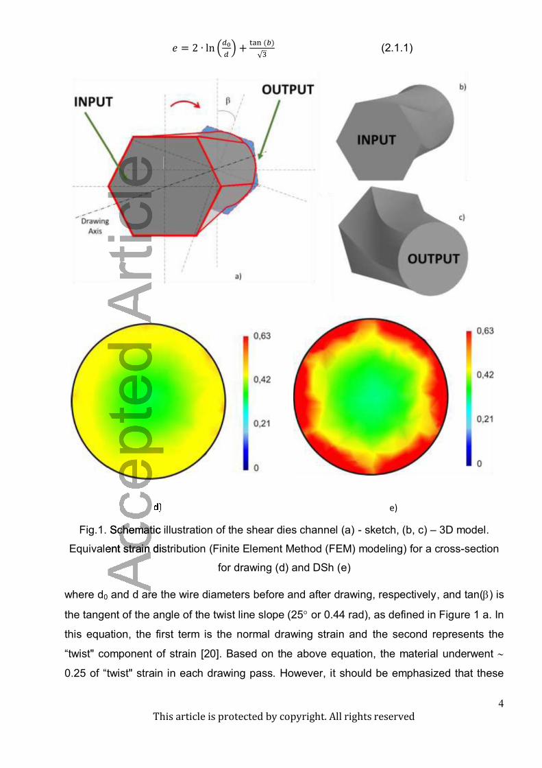
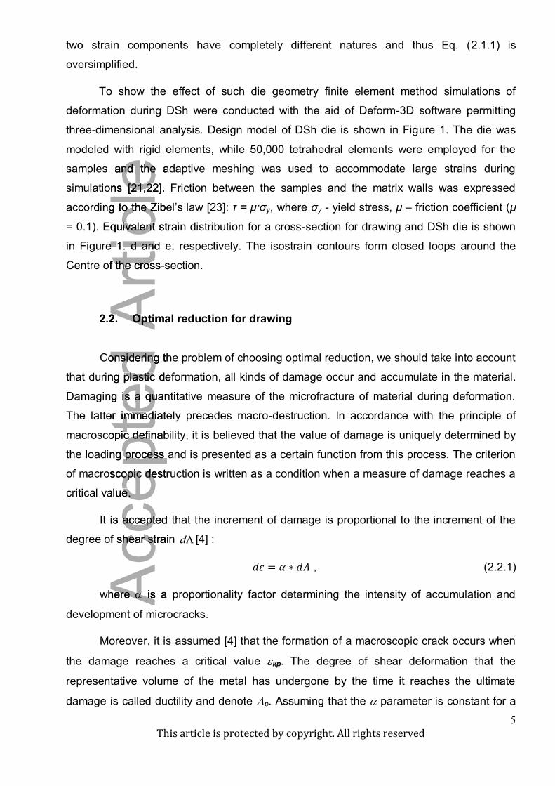
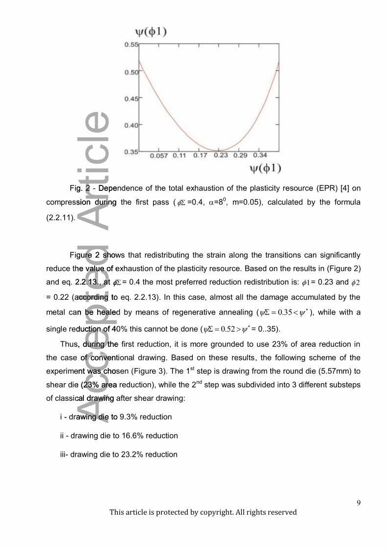
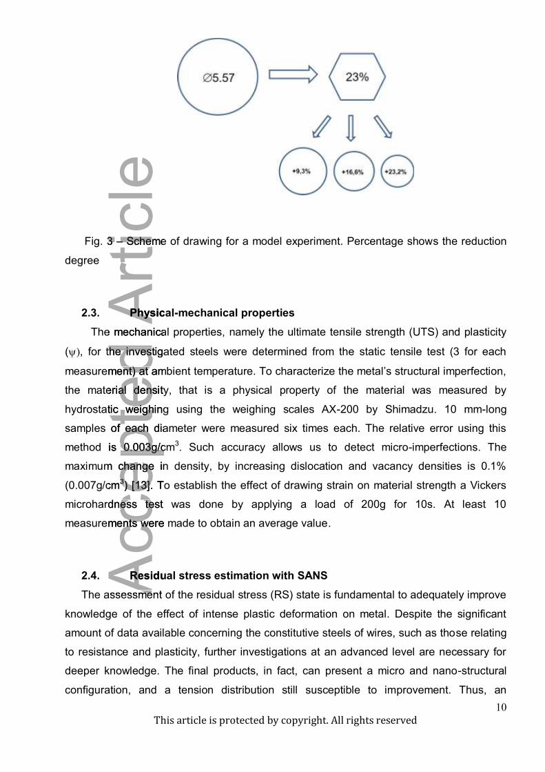
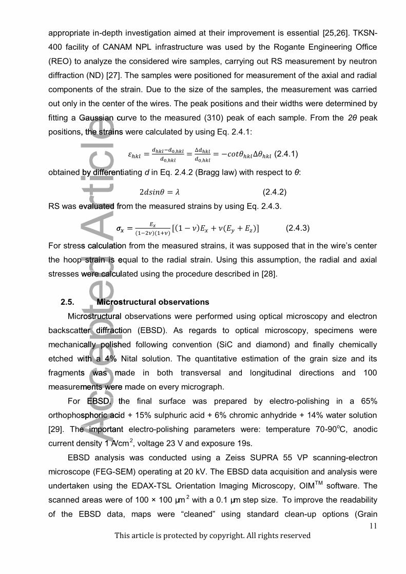
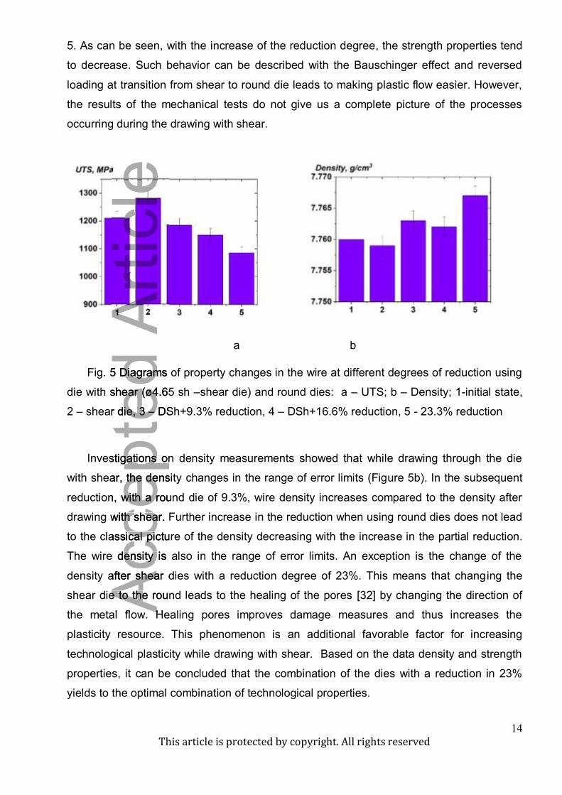
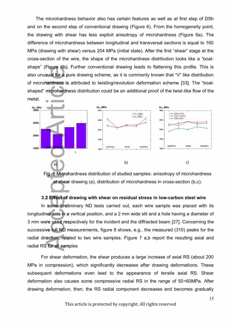
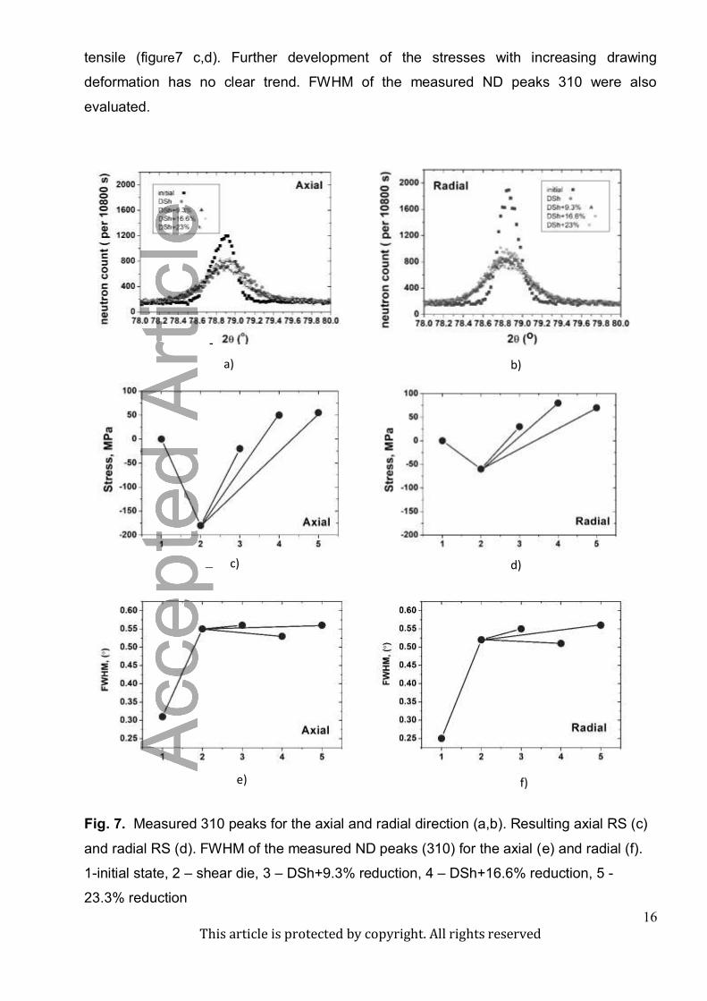
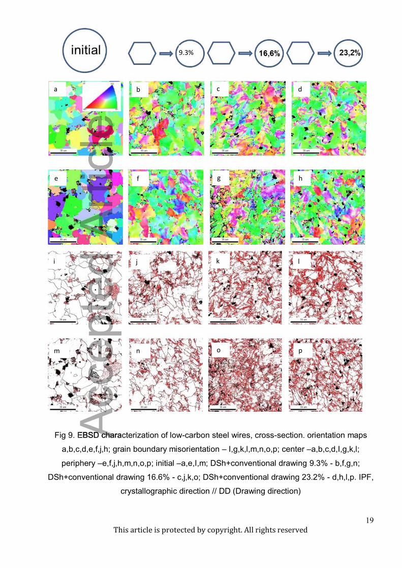