Embed Size (px)
Citation preview
DEVELOPMENT OF ULTRA- FINE GRAINED ALUMINIUM BY SEVERE PLASTIC DEFORMATION
A Thesis Submitted in partial fulfillment of the requirements for the award of the
Degree of
MASTER OF TECHNOLOGY
in
NEW MATERIALS AND PROCESSING TECHNOLOGY
BY WAHDAT ULLAH
(M.TECH /NMPT/07/05)
DEPARTMENT OF APPLIED PHYSICS BIRLA INSTITUTE OF TECHNOLOGY
MESRA-835215, RANCHI 2006
DECLARATION CERTIFICATE
This is to certify that the work presented in this thesis entitled
“DEVELOPMENT OF ULTRA-FINE GRAINED ALUMINIUM BY SEVERE PLASTIC DEFORMATION” in partial fulfillment of the
requirement for the award of degree of Master of Technology in New Materials and Processing Technology of Birla Institute of
Technology, Mesra, Ranchi is an authentic work carried out at the
National Metallurgical Laboratory (Jamshedpur) under our joint
supervision and guidance.
To the best of our knowledge, the content of this thesis does
not form a basis for the award of any previous degree to any one
else. Dr. P. K. Barhai Dr. V. C. Srivastava Professor Scientist Birla Institute of Technology National Metallurgical Laboratory Ranchi-835215 Jamshedpur-831007 Head Dean Department of Applied Physics (Post Graduate Studies) Birla Istitute of Technology Birla Institute of Technology Mesra,Ranchi-835215 Mesra,Ranchi-835215
CERTIFICATE OF APPROVAL
The foregoing thesis entitled “DEVELOPMENT OF ULTRA FINE GRAINED ALUMINIUM BY SEVERE PLASTIC DEFORMATION” is hereby approved as a creditable study of
research topic and has been presented in a satisfactory manner to
warrant its acceptance as prerequisite to the degree for which it has
been submitted.
It is understood that by this approval, the undersigned do not
necessarily endorse any conclusion drawn or opinion expressed
therein, but approve the thesis for the purpose for which it is
submitted. (Internal Examiner) (External Examiner)
Head of the Department (Chairman)
CONTENTS Contents i-ii
Acknowledgments iiii-iv
Preface v-vi
CHAPTER-I : Literature Review 1-22 1.1 Modern trends of ultrafine-grained materials forming 1
1.1.1 Bottom-up approach 1
1.1.2 Top-down approach 2
1.2 Severe plastic deformation
1.2.1 Accumulative roll bonding (ARB) 5
1.2.1.1 ARB process 5
1.2.1.2 Phenomena affecting interfacial bonding 7
1.2.1.3 Limitations due to edge cracking 7
1.2.1.4 Advantages 8
1.2.2 Equal channel angular pressing (ECAP)
1.2.2.1 ECAP process 8
1.2.2.2 Processing routes in ECAP 10
1.2.2.3 Advantages 10
1.2.2.4 Experimental factors influencing ECAP 12
1.3 Structural parameters of cold worked FCC metals 12
1.4 Deformation physics of nanao-crystalline metals processed 13
by SDP
1.5 Structure and properties of SPD processed UFG materials 16
1.6 Limitations of SPD methods of metals forming 19
1.7 Possible methods to improve ductility of nanostructured 21
metals and alloys
CHAPTER-II: Experimental details 23-26 2.1 Selection of material for SPD 23
2.2 Sample preparation and procedure for ARB 23
i
2.3 Sample preparation for microstructural analysis 25
2.4 Mechanical testing 26
2.5 Texture measurements 26
CHAPTER-III: Results 27-55 3.1 Interface characteristics 28
3.2 Microstructural evolution 30
3.2.1 Transmission electron microscopy 30
3.2.2 Atomic force microscopy 39
3.3 Evaluation of mechanical properties 39
3.3.1 Hardness measurements 39
3.3.2 Tensile properties 42
3.3.3 Tensile fracture behaviour 42
3.4 Evolution of texture 48
CHAPTER-IV: Discussion 56-60 Conclusions 61 Scope for future work 62-63 References 64-67
ii
ACKNOWLEDGEMENTS
I would like to express my deep sense of gratitude to Dr. V. C. Srivastava,
Scientist, Metal Extraction and forming Division, National Metallurgical Laboratory
(NML), Jamshedpur, and Dr. P. K. Barhai, Dean, Sponsored Research & Collaborative
projects and Professor & Head, Department of Applied Physics, B.I.T. Mesra, Ranchi for
their invaluable suggestions, excellent supervision, constant encouragement and critical
discussion throughout the research work and during the preparation of the manuscript.
The inspiration and friendly attitude of Dr. V. C. Srivastava at every stage of this work is
duly appreciated. It is indeed a great pleasure to be associated with him.
I am grateful to Professor S. P. Mehrotra, Director, National Metallurgical
Laboratory, Jamshedpur, for allowing me to carry out the project work and permitting
the use of necessary facilities for successful completion of the work.
My sincere thanks to Dr. Sandip Ghosh Chowdhury, Dr. Mainak Ghosh, Dr. A. K.
Parmanik, Dr. Venkateswarlu for their selfless support in texture and microstructural
analysis and also for their constant encouragement and fruitful suggestions. I would also
thank Dr. Goutam Das, for extending necessary facilities for optical microscopy.
I take this opportunity to thank Mr. P. K. De and Mr. A. Srinivasan, Scientists,
MEF Division, NML, Jamshedpur, for their constant encouragement, inspiration,
assistance and useful discussion throughout the project work. I would also like to thank
Mr. B. A. Lakra and Mr. M. Gunjan for their kind support in hardness measurement and
scanning electron microscopy of materials.
I express my deep sense of gratitude to Dr. G. G. Sarkar, Principal Scientific
officer, and Dr. S. K. Sinha, Reader, Department of Applied Physics, B.I.T. Mesra,
Ranchi, for their kind support and advice rendered during the course of my project work.
I also thank Dr..K. L. Hansda, Scientist (NML) for his constant encouragement
and support throughout my stay at NML, Jamshedpur.
I also take this opportunity to extend my thanks and gratitude towards all the
members of the faculty of Applied Physics Department, B.I.T. Mesra, Ranchi, for their
help in connection with this project work.
iii

I would also like to thank my friends and fellow colleagues Mr. Ravi Shekhar,
Mr. Randhir kumar, Mr. Sunil Tewary, Mr. Parshant Srivastava and many others who
have assisted me at all moments of need. Thanks to all other members of the faculty of
B.I.T. Mesra, and NML, Jamshedpur for their help, yet uncounted in making this project
and to see the light of success. Finally, I thank all personalities who either directly or
indirectly rendered help to complete the project work successfully.
I express my profound gratitude to my parents for their sacrifices, constant
support, understanding and encouragement extended.
Date: 28.05.2007 Wahdat Ullah Place: Ranchi M.Tech.(B.I.T,Mesra)
iv
Nanoscale science and t
materials have made profound
believe that the nanoscale scien
due to the unique properties of
of nanotechnology. Two basic
the synthesis of nanomaterials
approaches. In the bottam up a
themselves can be used as the b
Whereas, in the “tops down” ap
-grained /nanostructured materi
polycrystalline materials having
UFG materials may lie within th
In order to convert a coa
necessary to impose an excepti
dislocations which, in turn, re-a
in strain. Conventional metal
restricted in their ability to prod
is a limitation on the overall str
a very high strain requires corr
the work-pieces. Second, the st
insufficient to give rise to UFG
metallic alloys at ambient tem
solidification and vapor conden
these processes are restricted t
limitations, there is a paradigm
alternative processing techniqu
technique is one of such process
low temperatures.
PREFACE
echnology is experiencing a rapid development and nano-
impact on every field of materials research. Scientists
ce and technology will bring revolutions in human history
nano-materials. Nanomaterials are the fundamental basis
and complementary approaches have been developed for
. These are known as “bottom up” and “top down”
pproach, atoms, molecules and even nanosize particles
uilding blocks for the creation of complex nanostructures.
proach coarse-grained materials are refined into ultrafine
als. Ultrafine grained (UFG) materials may be defined as
average grain size less than ~1µm. The grain sizes of
e sub-micrometer (100-1000 nm) range.
rse grained solid into a material with ultrafine grains, it is
onally high strain in order to introduce a high density of
rrange to form an array of grain boundaries with increase
forming procedures, such as extrusion or rolling, are
uce UFG structures for two important reasons. First, there
ains that may be imposed using these procedures because
esponding reductions in the cross-sectional dimension of
rains imposed in conventional processing are limited and
structures because of the generally low workability of
peratures. Another conventional method, such as rapid
sation, are able to refine the materials up to nanoscale, but
o only thin layers/sections. As a consequence of these
shift in the synthesis routes for nanoscale materials and
es have evolved. The severe plastic deformation (SPD)
es, where extremely high strains are imposed at relatively
v
During the last two decade SPD has emerged as a widely known procedure for the
grain refinement of metals and alloys into sub-micrometer or even nanometer range.
Synthesis of UFG materials by SPD refers to various experimental procedures of metal
forming that may be used to impose very high strains on materials leading to exceptional
grain refinement. For production of bulk UFG materials with equiaxed microstructure
and high angle grain boundary misorientation, accumulative roll bonding (ARB) and
equal channel angular pressing are the two well known SPD methods.
Materials processed by SPD have shown superior mechanical properties such as
high strength, excellent fatigue life, high toughness and low temperature superplasticity.
As the specific material properties are becoming stringent in the current developmental
scenario, there is a continuing increase in market requirements for high-strength metals
and alloys. This finds applications in aerospace, automobile, transportation, food and
chemical processing, electronics, and conventional defence industries. The market
emphasis and exceptional material properties requirements have led to a considerable
interest in the development of ultrafine-grained/nanomaterials by severe plastic
deformation.
Therefore, the present work has been undertaken to develop ultrafine-grained
aluminum by severe plastic deformation method and to examine the microstructure and
mechanical properties by different characterizing tools. An important objective of this
work is to identify and quantify interrelationships between the deformation mechanisms
active during grain refinement process and to determine their influence on the mechanical
behavior of UFG aluminum processed by accumulative roll bonding technique, one of the
variants of severe plastic deformation.
vi
CHAPTER - I
w
1. LITERATURE RE
1.1 Modern trends o
As has been al
approaches for the syn
attempt to illustrate the
routes and their effect
from the figure that a
plastic deformation, ca
find numerous applicat
during processing. A
nanomaterials is show
reaches in nanoscale r
two broad approaches w
1.1.1 Bottom up app
In the “botto
nanoparticles can be u
Most of the bottom-up
nanostructured materia
consolidated into bulk
inert gas condensation
milling with subsequen
isostatic pressing (Luto
Literature Revie
VIEW
f ultrafine-grained materials forming
ready mentioned in the previous section, there are two different
thesis of UFG (Zhu and Liao, 2004), in the present section we
se approaches in detail. A schematic representation of processing
on final grain size refinement is given in figure 1.1. It is obvious
ccumulative roll bonding (ARB) and ECAP, variants of severe
n be effectively used to produce UFG materials. Nanomaterials
ions depending upon the structure and property variation obtained
summary of the possible variation in the specific properties of
n in figure 1.2. This describes the variation when the material
egime. The synthesis route of nanomaterials can be divided into
hich are described in the following sections.
roach
m-up” approach of synthesis, atoms, molecules and even
sed as the building blocks for the creation of complex structures.
approaches emphasize use of nanopowders for the synthesis of
ls. For structural applications, the nanopowders need to be
nanostructured materials. Examples of these techniques include
(Gleiter, 1981 and 1989), electrodeposition (Erb et al.,1993), ball
t consolidation (Koch and Cho, 1992) and cryomilling with hot
n et al.,1989 and Witkin and Lavernia, 2006). In practice, these
techniques are often limited to the production of fairly small samples that may be useful
for applications in fields such as electronic devices but are generally not appropriate for
large-scale structural applications. Furthermore, the finished products from these
techniques invariably contain some degree of residual porosity and a low level of
contamination, which is introduced during the fabrication procedure. Recent research has
shown that large bulk solids, in an essentially fully-dense state, may be produced by
combining cryomilling and hot isostatic pressing with subsequent extrusion (Han et al.,
2004) but the operation of this combined procedure is expensive and at present it is not
easily adapted for the production and utilization of structural alloys in large-scale
industrial applications.
1.1.2 Top-down approach
The “top-down” processes are effective examples of solid-state processing of
materials. In this synthesis approach, coarse-grained materials are refined into
nanostructured materials through heavy straining or shock loading. This approach
obviates the limitation of small product sizes and also the contamination that is inherent
features of materials produced using the ‘‘bottom-up’’ approach. This has an additional
advantage that it can be readily applied to a wide range of pre-selected alloys. The first
observations of the production of UFG microstructures using this approach appeared in
the scientific literature in the early 1990s. (Valiev et al., 1990 and Valiev et al., 1991). It
is important to note that these early publications provided a direct demonstration of the
ability to employ heavy plastic straining in the production of bulk materials having fairly
homogeneous and equiaxed microstructures with grain sizes in the submicrometer range.
1.2 Severe plastic deformation
Severe plastic deformation term (SPD) is a modified form of “intensive plastic
deformation”. The term severe plastic deformation was first introduced by Musalimove
and Valiev in 1992, where they described the deformation of an Al-4% Cu-0.5%Zr alloy
[R.S. Musalimove and R.Z. Valiev (1992)]. In the last decade, this process established
- 2 -

itself very well as an effective method for the production of bulk ultra fine-grained (UFG)
metallic materials (Valiev et al., 1993; Valiev et al., 2000; Valiev, 2004). Several
methods of SPD are now available for refining the microstructure in order to achieve
superior strength and other properties e.g.
* Equal-channel angular pressing (ECAP) (Valiev et al., 1991, Segal et al., 1981)
* High-pressure torsion (HPT) (Smirnova et al., 1986; Zhilyaev et al., 2003)
* Multi-directional forging (Salishchev et al., 1993; Valitov et al., 1994; Sitdikov
et al., 2004)
* Twist extrusion (Beygelzimer et al., 2004; Varyutkhin et al., 2006)
* Cyclic-extrusion/compression (Richert and Ritchert, 1986; Richert et al., 1999)
* Reciprocating extrusion (Chu et al., 2001)
* Repetitive corrugation and straightening (RCS) (Huang et al., 2001; Zhu et al.,
2001)
* Constrained groove pressing (CGP) (Shin et al., 2002)
* Cylinder covered compression (CCC) (Zhao et al., 2004)
* Accumulative roll-bonding (ARB) (Saito et al., 1998)
* Friction stir processing (FSP) (Rhodes et al., 1997; Mishra and Ma, 2005)
* Submerged friction stir processing (SFSP) (Hofmann and Vecchio, 2005)
Conventional structural metals
TMCP
Super metals
Sintering of MA powder, ECAP, ARB
Consolidation of ultrafine particles Electrodeposition
Several plastic deformation Crystallization of amorphous
Grain size
10 µm 1 µm 100 nm 10 nm 1 nm 0.1 nm
Polycrystalline Nanocrystalline Amorphous
Fig. 1.1: Typical grain size range generated by different materials
- 3 -
All of these procedures are capable of introducing large plastic strain leading to
significant microstructural refinement in bulk crystalline solids. Some of these
techniques, such as ARB, ECAP, multi-directional forging and HPT, are already well-
established methods for producing UFG materials where, depending upon the crystal
structure, the processed microstructures have grain sizes lying typically within the range
of ~70–500 nm. The other techniques are currently under development for this purpose.
Of these various procedures, accumulative roll bonding (ARB) process of metal
forming is an especially attractive processing technique for producing ultrafine grained
(UFG) materials (Tsuji et al., 2003; Li et al., 2006; Lee et al., 2002). It is a simple
procedure that makes use of a conventional roll bonding procedure, which is easily
performed on a wide range of metals and alloys. Processing by ARB uses equipments
that are readily available in most laboratories. These attractive features have led to many
experimental studies and new developments in ARB processing over the last decade.
Nanocrystalline materials
Elastic Modulus
Ductility and toughness
CTE
Strength and hardness
Diffusivity
Thermal conductivity
Magnetic properties
Electrical resistivity
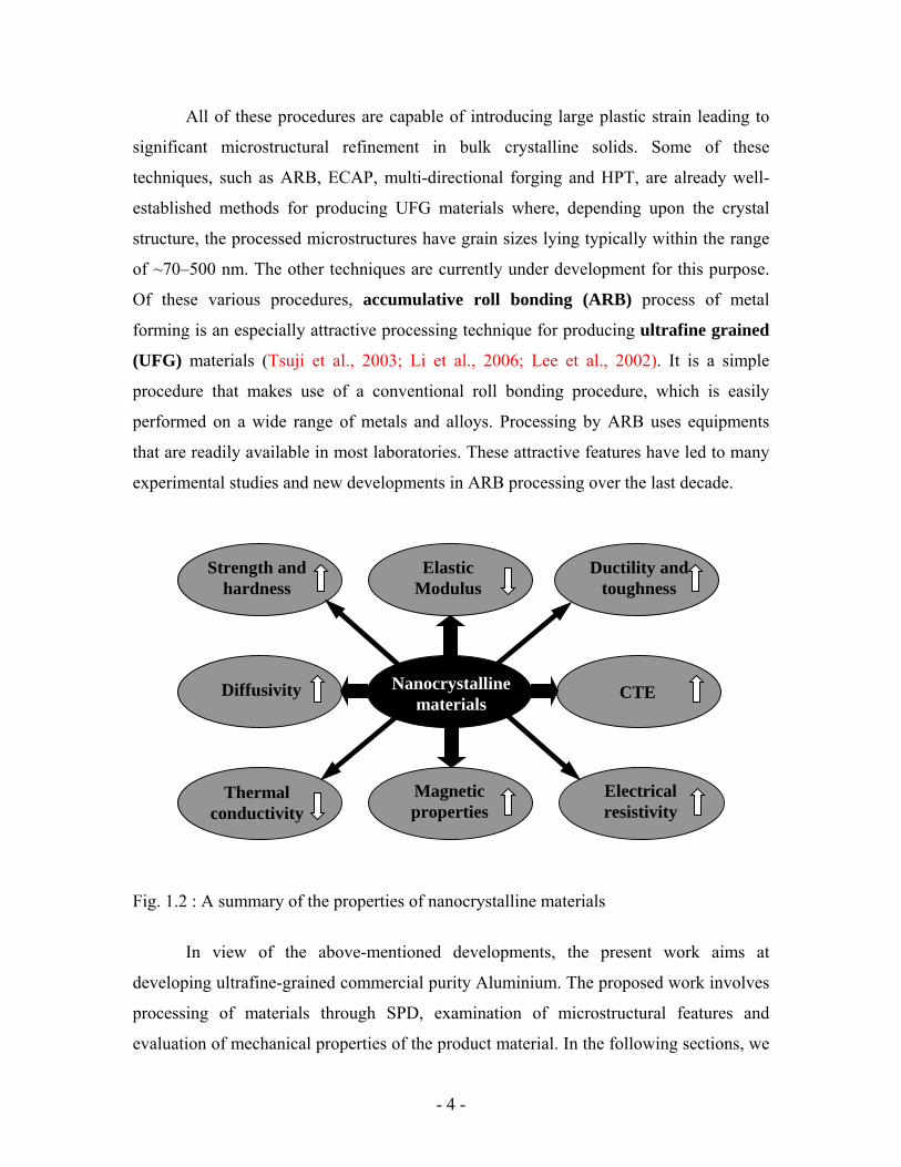
Fig. 1.2 : A summary of the properties of nanocrystalline materials
In view of the above-mentioned developments, the present work aims at
developing ultrafine-grained commercial purity Aluminium. The proposed work involves
processing of materials through SPD, examination of microstructural features and
evaluation of mechanical properties of the product material. In the following sections, we
- 4 -
have attempted to give a brief introduction to accumulative roll bonding and equal
channel angular pressing, most commonly used severe plastic deformation processes.
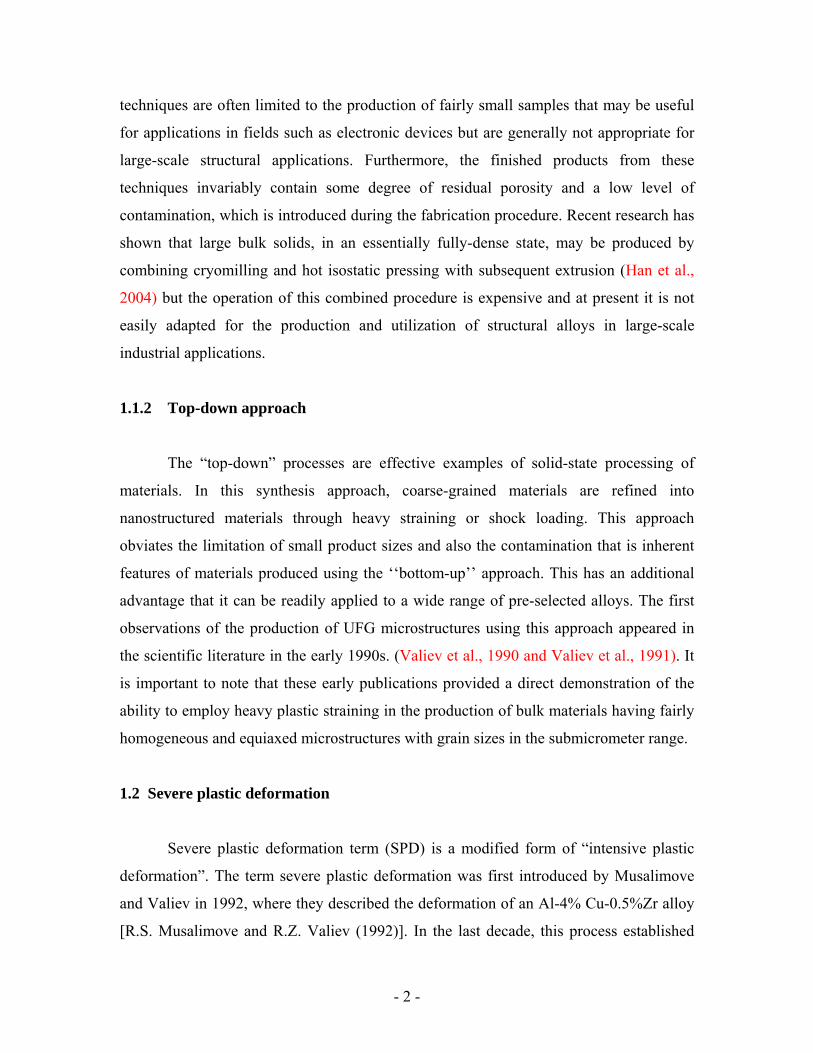
1.2.1 Accumulative Roll Bonding (ARB)
1.2.1.1 ARB Process
The ARB process, which forms the basis of this study, can be explained on the
basis of a schematic diagram, as shown in Fig. 1.3. In this process, thin sheets of
metal/alloy are taken and stacked together for roll bonding. The surfaces to be joined are
roughened and cleaned; the two parts are stacked and roll bonded with approximately
50% reduction in thickness. The bonded sheet is cut into two halves and again stacked
after proper surface cleaning and rolled. Several researchers have shown that the process
may be repeated several times, if some precautions like removing the edge cracks are
taken. Several passes of repeated roll bonding may lead to a large reduction in the initial
sheet thickness. A little consideration would indicate that after six such passes a total
number of 64 layers could be introduced. This means that an initial 2 mm thick sheet
would be reduced to (2/64) mm if a reduction of 50% is achieved during each pass. This
process can be carried out either in hot condition or cold condition. However, it is
beneficial to work bellow the recrystallisation temperature of the materials. If Thomologous
of roll bonding is close to 0.5Tm, sound bonding is achieved by reduction of approx. 50%.
However, it may vary from materials to materials. Hence, the material can be bonded
together without recrystallization. ARB can be used to introduce ultra high plastic strain
without any geometrical change, if reduction is maintained to 50% in every rolling pass,
as increase in width is negligible if the aspect ratio, i.e., ratio of width to thickness is >10.
If reduction is 50% per cycle, the thickness of initial strip after n cycles is
nt
t20=
where t0 = initial thickness of strips.
- 5 -
Total reduction ntt
ttt
tr 211
01
00 −=−=−
=
The assumption of von Mises yield criterion (Krallics and Lenard, 2004) and plane strain
condition, i.e., no lateral spreading, the equivalent plastic strain is
n
finaltinitialt
⎟⎟⎟
⎠
⎞
⎜⎜⎜
⎝
⎛
⎟⎟⎠
⎞⎜⎜⎝
⎛= ln
32ε
= 0.80 n
= 4.80 (for 6 passes)
Sheets
Rolls
Cutting
Stacking
Fig. 1.3: Schematic diagram showing ARB process
There are two possible additional mechanisms in the ARB process, which differ
from other high straining processes. The first possible mechanism is the effect of severe
shear deformation just below the surface. It has been reported that severe shear
deformation is introduced by friction between the work piece and the roll under dry
conditions. This shear deformation significantly increases the equivalent strain and
promotes grain refinement (Li et al., 2006). Moreover, these highly deformed surface
layers are further introduced into the interior of the material by repetitive folding and
- 6 -
rolling. The other mechanism is the introduction of new interfaces. A large number of
interfaces are introduced by several ARB cycles. These interfaces show a well-developed
fibrous structure. The oxide films on the surfaces, as well as inclusions, are dispersed
uniformly by repetition. These second phase particles contribute to strengthening and
may act as obstacle for grain growth (Lee et al., 2002).
1.2.1.2 Phenomena affecting interfacial bonding
It is obvious from previous sections that accumulative roll bonding process is a cold
welding process forming a bond between participating metallic layers. The strength of
bonds depends on several metallurgical and mechanical factors. And also, the bond
quality reflects its presence in the mechanical properties of the ARBed materials.
Therefore, a good bonding between layers becomes of paramount importance in this
process. The bond quality, in general, depends on the following material and process
parameters. (Krallics and Lenard, 200).
The grain size and ductility of the materials
Cleanliness and roughness of the joining faces
Closeness of faces and roll pressure
Duration of the contact
Rolling temperature
Oxide formation on the joining faces
Oxide fracture during rolling
1.2.1.3 Limitation due to edge cracking
The occurrence of edge cracks on the samples after a few passes limits the
application of the ARB process. One of the reasons for edge cracking behavior is due to
the continuous increase in hardness and strength of the material after each pass due to
which the ductility of the material decreases. The second reason is the presence of
precipitates that hinder the movement of dislocations, thus resulting in nucleation and
- 7 -
propagation of edge cracks due to dislocation pile up. In ARB process, 99% reduction of
experimental material could be achieved, which is much larger than what can be achieved
in one conventional pass or by forging without edge cracking. The large straining during
reduction of material thickness is another cause of edge cracking during ARB. As the
edge cracks further propagate in the material with subsequent ARB cycles, proper
trimming of the edges, sometimes, becomes necessary to achieve more deformation
without crack propagation. (Krallics and Lenard, 2004).
1.2.1.4 Advantages
The major advantages of this process against other high straining process are:
It has the cabability of high productivity and the feasibility of bulk material
production.
It does not require any special machines, because the roll bonding is widely
adopted in clad metal production.
The materials processed by this route have almost homogeneous
microstructure.
It can be applied to materials with different crystal structures and to materials
ranging from precipitation-hardened alloys to intermetallics and metal–matrix
composites.
1.2.2 Equal Channel Angular Pressing (ECAP)
1.2.2.1 ECAP process
Equal-channel angular pressing (ECAP) is the most studied SPD processing
technique (Valieve at al., 2006). It is an interesting and demandable method for
modifying microstructure in producing ultrafine grained (UFG) materials. A schematic
diagram of ECAP is shown in figure 1.4. In this process a rod/square shaped billet is
pressed through a die constrained within an equal channel cross section, which is bent at
- 8 -
an abrupt angle. A shear strain is introduced when the billet passes through the point of
intersection of the two parts of the channel. Since the cross-sectional dimensions of the
billet remain unchanged, the pressings may be repeated to attain exceptionally high
strains. The equivalent strain ε, introduced in ECAP, is determined by a relationship
incorporating the angle (Φ) between the two parts of the channel and the angle (Ψ)
representing the outer arc of curvature, where the two parts of the channel intersect. The
relationship is given by (Meyers et al., 2005).
⎥⎦
⎤⎢⎣
⎡
⎭⎬⎫
⎩⎨⎧
⎟⎠⎞
⎜⎝⎛+⎟
⎠⎞
⎜⎝⎛+
⎭⎬⎫
⎩⎨⎧
⎟⎠⎞
⎜⎝⎛+⎟
⎠⎞
⎜⎝⎛=
22cos
22cot2
3ψφψψφε ecN
Where N is the number of the passes through the die.
φ
Experimentalmaterial
Plunger Die
Fig. 1.4: A schematic diagram showing ECAP process
- 9 -
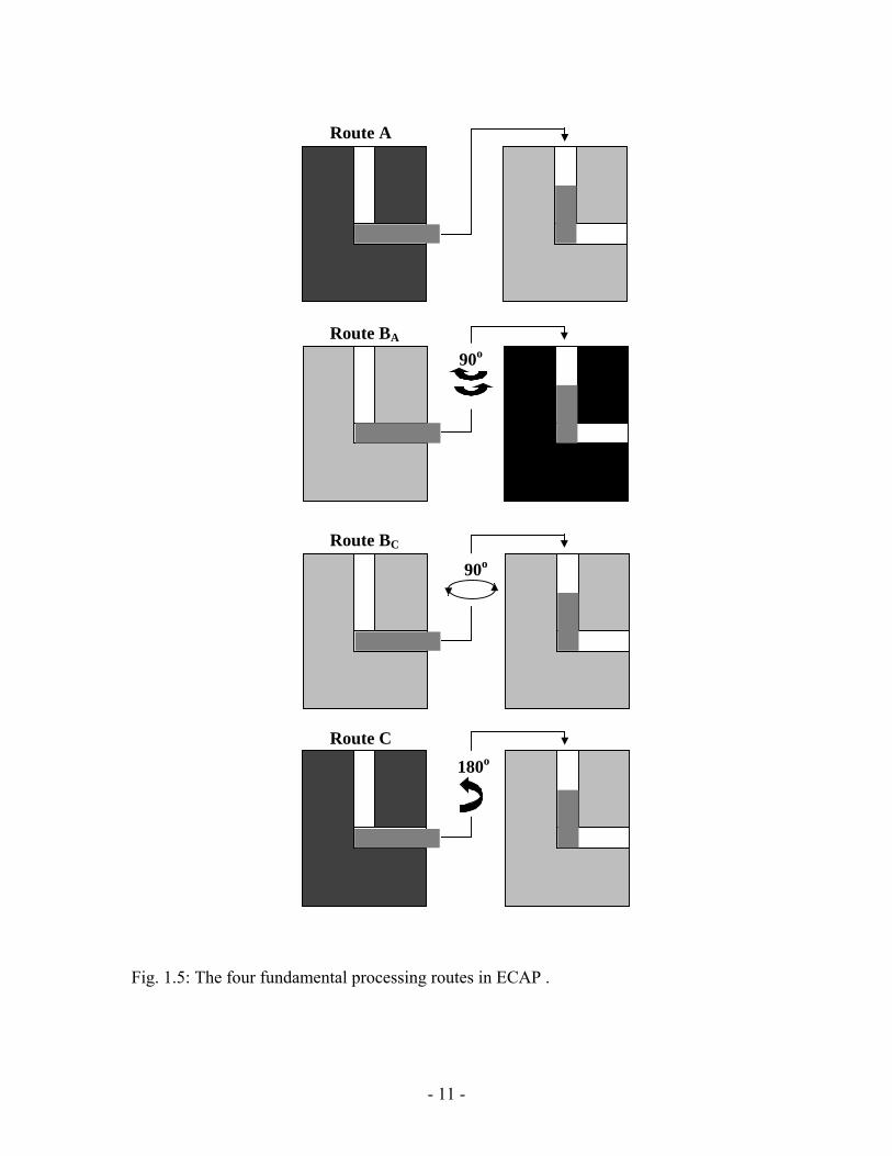
1.2.2.2 Processing routes in ECAP
There are four basic processing routes in ECAP and these routes introduce
different shear routes during the pressing operation so that they lead to significant
differences in the microstructures produced by ECAP (Nemoto et al., 1998; Horita et al.,
2000; Furukawa et al., 2003). The four different processing routes are summarized
schematically in Fig. 5. This shows that the sample is pressed without rotation (route A),
the sample is rotated by 90o in alternate directions between consecutive passes (route BA),
the sample is rotated by 90o in the same sense (either clockwise or counterclockwise)
between each pass (route BC) and the sample is rotated by 180o between passes (route C).
Various combinations of these routes are also possible, such as combining routes BC and
C by alternating rotations through 90o and 180o after every pass, but in practice the
experimental evidence obtained to date suggests that these more complex combinations
lead to no additional improvement in mechanical properties of the as-pressed materials.
Accordingly, for the simple processing of Bars or rods, attention is generally devoted
exclusively to the four processing routes delineate in Figure 1.5.
1.2.2.3 Advantages
The following reasons make this method of high straining more preferable against other
processes:
It is a simple technique that is easily performed on a wide range of alloys,
except the construction of the die.
It can also be used to materials with different crystal structures and to many
materials ranging from precipitation-hardened alloys to intermetallics and metal-
matrix composites.
Reasonable homogeneity is attained through most of the as-pressed billet
provide the pressings of relatively large samples.
The dimension of the billet remains unchanged, therefore, pressings may be
repeated to attain exceptionally high strains.
- 10 -
Route A
Route BA
Route BC
Route C
90o
90o
180o
Fig. 1.5: The four fundamental processing routes in ECAP .
- 11 -

1.2.2.4 Experimental factors influencing ECAP
When materials are processed using ECAP, several different factors influence the
workability and the microstructural characteristics of the as-pressed billets. These factors
can be enumerated as follows: (Valiev et al., 2006)
The angle between channels of the die (Φ)
The angle of curvature (Ψ )
The pressing speed of the punch in the die
The material temperature
Internal heating during ECAP
Back pressure on the punch
1.3 Structural parameters of cold worked FCC metals
Since the present work has been undertaken to develop ultrafine-grained aluminum
(Face Centred Cubic structure) by severe plastic deformation method and to examine the
microstructure and mechanical properties by different characterizing tools, it is necessary
to have an idea of the structural features of FCC metals and alloys. The structural features
of SPD processed metals are quite complex and they are characterized not only by the
formation of ultrafine grains but also the presence of non-equilibrium grain boundaries
with a high density of extrinsic dislocations and vacancies, high lattice distortions, and
possibly, changes in the local phase composition. The genesis of UFG structure produced
by SPD techniques is not yet fully understood. While some authors relate them to in-situ
recrystallisation (Lapovok et al., 2005), others have different opinions about the
mechanism of UFG formation. Recently, a series of studies led by (Hughes and Hansen,
1997; Hughes and Hansen, 2000; Liu et al., 2002) showed that quantitative structural
parameters of cold-worked FCC metals could be measured. This achievement has great
technical importance due to the fact that the use of these quantitative parameters,
modeling of the deformation microstructure can be performed. Dislocations generated by
plastic deformation are not randomly distributed. They accumulate at dislocation walls,
and the regions surrounded by these dislocation walls have relatively low density of
dislocations. These dislocation walls may be classified into two types: (1) geometrically
- 12 -
necessary boundaries (GNB) and (2) incidental dislocation boundaries (IDB), due to their
different formation mechanisms. When a grain is deformed, it is sub-divided into “cell
blocks”. The dislocation walls that separate cell-blocks are GNB. The GNBs
accommodate the misorientation between neighboring blocks, which deform with
different slip system combinations or by different shear amplitudes. Each cell-block is
further divided into several cells. The geometrically necessary dislocations are generated
in order to maintain continuity of the polycrystalline material. The dislocation walls that
separate cells are IDBS, which are formed as a result of statistical trapping of glide
dislocations. As deformation proceeds, both the cell-blocks and the cell shrink in size, but
the cell blocks shrink in size more rapidly than the cells do. Eventually, each cell
becomes a cell-block.
1.4 The deformation physics of nanocrystalline metals processed by SPD
One of the important objectives of the present work is to identify interrelationship
between the deformation mechanisms active during grain refinement process and to
determine their influence on the mechanical behavior of UFG aluminum processed by
accumulative roll bonding technique. There are various physical models related to
interpretation of the physics of deformation of nanocrystalline metals and alloys. The first
model was proposed by Pande et al. (Pande et al., 1993) and further developed by
Armstrong and Coworkers (Armstrong and Hughes, 1999). According to this model the
dislocations in the SPD processed metals and alloys are assumed to be in the center of the
grain. As the grain size is reduced, the number of dislocations is eventually reduced to
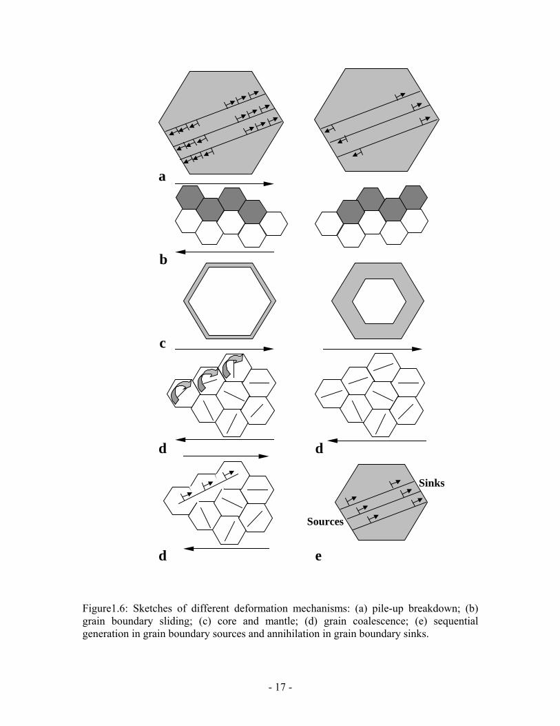
one and the stress amplification effect is lost. Figure 1.6a shows the individual
dislocations (positive and negative) arrested at opposing grain boundaries and all
dislocations pile-up at the grain boundaries.
The second model was proposed by Chokshi el at. (Chokshi et al., 1989). He
predicted that the grain-boundary sliding plays a major role in nanocrystalline metals and
alloys at ambient temperature. Simple grain boundary sliding is schemtically shown in
figure 1.6b, and it could be responsible for negative slope in grain size domain d<10nm.
In several recent experiments, the active development of grain boundary sliding was
- 13 -

revealed directly in UFG aluminium during deformation at room temperature through the
use of atomic force microscopy and depth-sensing indentation testing (Chinh et al.,
2006). The sliding contribution in these experiments was estimated as ~70% from
measurements of the surface profiles around hardness indentation, thereby confirming the
significance of sliding in the deformation of UFG structures. It is important to note that
these data correlate closely with results demonstrating an increased strain rate sensitivity
of the flow stress in UFG metals. The question remains why grain boundary sliding takes
place in nanostructured materials produced by SPD at temperatures that are relatively low
in comparison with the absolute melting temperatures of the materials. Thus, ambient
temperature for pure aluminum corresponds to an homologous temperature of only ~0.32
Tm, where Tm is the absolute melting temperature of the material. Since grain boundary
sliding is a diffusion-controlled process, it should occur preferentially at high
temperatures where diffusion rates are reasonably rapid (Gifkins and Langdon, 1964). A
possible explanation for the occurrence of sliding in UFG metals is that diffusion is more
rapid in SPD-produced metals with highly non-equilibrium grain boundaries.
Experiments have shown that in metals produced by SPD, the diffusion coefficient
increases considerably, often by two or three orders of magnitude, and this is associated
directly with the presence of non-equilibrium grain boundaries. Therefore, the grain
boundary sliding is easier in these ultrafine-grained metals and develops during straining
at lower temperatures leading to the possibility of observing increased ductility. It is well
known in this connection that enhanced sliding in nanostructured metals may lead to
superplasticity even at relatively low temperatures. The recent results obtained from
modeling and experiments provide strong support for the proposal that new deformation
mechanisms, that are not typical under the experimental conditions in conventional
coarse-grained materials, may proceed actively in metals with UFG microstructures.
Plastic flow occurring under conditions of high temperature creep is one of the
most internationally recognized mechanisms of deformation of a coarse-grained
polycrystal. Following the approach developed many year ago by Bird and co-workers
(Bird et al., 1969). They suggested that the steady state creep rateε& , is generally
expressed through a relationship of the form
- 14 -
n
G
p
db
kTADGb
⎟⎠⎞
⎜⎝⎛
⎟⎟⎠
⎞⎜⎜⎝
⎛= σε& (1)
where, D is the diffusion coefficient (= ⎟⎠⎞
⎜⎝⎛−
RTQD exp0 where D0 is a frequency factor, Q
the appropriate activation energy for the diffusion process, R the gas constant), G the
shear modulus, b the Burgers vector, K the Bolzmann’s constant, T the absolute
temperature, d the grain size and σ the applied stress, P and n are the constants define as
the inverse grain size exponent and the exponent respectively and A is the dimensionless
constant.
Diffusion creep and grain boundary sliding are important flow processes
associated with the presence of boundaries in polycrystalline materials. Diffusion creep
occurs because there is an excess of vacancies along grain boundaries experiencing a
tensile stress and a corresponding depletion of vacancies along grain boundaries
experiencing a compressive stress. Vacancy flow takes place to restore the equilibrium
conditions and this leads to an elongation of the grains along the tensile axis. There are
two separate types of diffusion creep (1) Nabarro-Herring creep, where the vacancies
diffuse through the crystalline lattice with n=1, p=2 and D=Dl (lattice self diffusion
coefficient) (Nabarro, 1950) and (2) Coble creep where the vacancies diffuse along the
grain boundaries with n=1, p=3 and D=Dgb (grain boundary diffusion coefficient).
As the grain boundary sliding refers to the relative displacement of adjacent
grains under the action of the applied stress, sliding of irregularly shaped grains cannot
occur without some form of accommodation mechanism, and in practice the sliding is
accommodated by intragranular slip in the adjacent grains. If the grain size is large in
comparison with the equilibrium subgrain size, λ ,subgrains are formed in the grains
during creep, the dislocations pile up and climb into these subgrain boundaries and the
rate of sliding is given by equation (1) with n=1, p=1 and D=Dl. However, if the grain
size is smaller than λ as in superplastic materials, no subgrains are formed and the
dislocations climb into the opposite grain boundary with n=1, p=2 and D=Dgb. (Langdon,
1994)
- 15 -
In one another model Li (Li, 1963) recognized that grain boundaries could serve
as sources of dislocations. Figure 1.6c shows a grain divided into two regions; a central
core and the grain-boundary region called ‘mantle’. The mechanical response of these
two regions is different, with work hardening being more pronounced in the mantle. This
is because the grain interiors are subjected to a more homogeneous state of stress, while
in the mantle several other factors contribute to the increased hardening. The ratio
between the volumes of these two regions is independent of grain size. There is a simple
experimental evidence for the development of a mantle in the conventional
polycrystalline domain (Zehetbauer et al., 1999). As the grain size is reduced, the mantle
becomes proportionally larger, as shown in the right side of figure 1.6c.
Some literature shows the evidence of shear band formation (Wang, 2006). Figure
1.6d shows how neighbouring equiaxed nanograins can, upon rotating, create elongated
grains that act as favored paths for plastic deformation. The major slip orientations and
their rotation are marked in the grains by short segments in the centers of the grains.
The most important and significant results of the physical process that occur
during plastic deformation of nanocrystalline metals have been obtained by molecular
dynamic (MD) simulation. According to this model (Meyers, 2006), the grain boundaries
act as both dislocation sources and sinks and continuous refinement of grain size leads to
partial dislocation emission from grain boundaries as well as deformation twinning
(Figure 1.6e). Even in metals with medium high stacking fault energies such as Al and
Cu. As the grain size is reduced into the nanocrystelline range, dislocations can travel
unimpeded throughout grains. Thus, dislocations emitted from one boundary can be
annihilated at the opposite boundary (Asaro et al., 2003). The reduction in grain size of
materials makes twinning more difficult and responsible for the flow of nanocrystelline
FCC metals plastically.
1.5 Structure and properties of SPD Processed UFG materials
The grain size of the crystalline materials plays a significant and often a
dominant, role on its mechanical and physical properties. The mechanical and physical
properties of nanocrystelline or ultrafine-grained (UFG) materials differ from their
- 16 -
a
b
c
d d
d e
Sources
Sinks
Figure1.6: Sketches of different deformation mechanisms: (a) pile-up breakdown; (b) grain boundary sliding; (c) core and mantle; (d) grain coalescence; (e) sequential generation in grain boundary sources and annihilation in grain boundary sinks.
- 17 -
coarse-grained (CG) counterpart. The strength of the polycrystalline materials is related
to the grain size, d, through the Hall-Petch equation (Hall, 1951; Petch, 1953), which
states that the yield stress σ, is given by
21
0−
+= dykσσ (1)
Where σ0 is termed as the friction stress and ky is a constant of yielding. It follows from
Equation (1) that the strength increases with a reduction in the grain size. The average
grain size achieved in pure metals using various SPD techniques usually lies in the range
of ~150-300nm but in alloys it may be significantly smaller. For example, using High-
pressure torsion (HPT) with the intermetallic Ni3Al produced a grain size of 60 nm in Al-
Ni alloys and in TiNi alloys processing by HPT led to total amorphization (Liao et al.,
2004). The smallest grain size achievable by SPD cannot be smaller than the length scale
of the precursor structure and thus of the dislocation cell size, which has an order of
magnitude of some hundreds of nanometers. The most important features of SPD
processing is that it leads to an exceptional grain refinement and thereby provides an
opporunity to significantly enhance the properties of materials as well as to attain novel
and/or unique properties. Table 1.1 shows the mechanical properties of various materials
processed by SPD. One such unique property is the unexpected combination of high
strength and high ductility. The specific processing of SPD and the associated
simultaneous improvement of both strength and ductility is probably responsible also for
the marked enhancement of fatigue strength and fracture toughness in UFG materials. As
the grain size decreases to submicron-grained or nanocrystelline range, the fraction of
grain boundary to matrix increases. This can cause the deformation mode to change from
grain dominated in large grains to grain boundary dominated in small grain regimes. For
smaller grain sizes, the empirical Hall-Petch relationship is expected to break down
because it is based on dislocation pile up at the boundaries. As the grain size decreases,
the number of “pile up” dislocations becomes smaller and, eventually, at a critical grain
size, dislocations can no longer pile up at grain boundaries. Consequently, at this critical
grain size, the yield stress no longer increases with decreasing grain size. It is believed
that grain boundary processes, such as grain boundary sliding, grain rotation, or interface-
- 18 -
controlled plasticity, are some of the mechanisms that can control the deformation at
these small grain sizes. For this reason, the dislocation source length and dislocation
mean free path need to be considered in ultrafine grains (Anderson et al., 2003)
Another extraordinary property of UFG materials is their ability to exhibit
superplasticity at high strain rates and at usually low temperatures, which provides an
opportunity for the rapid superplastic forming of complex-shaped parts for use in the
transportation and consumer product industries (Xu et al., 2004). Although most efforts
to date have been directed toward improving the mechanical properties of structural
materials processed by SPD, there is also recent evidence for other interesting
developments. A general observation is that the increase in grain boundary area
introduced by SPD can lead to enhancement in various kinetic properties of metallic
materials. For example, it was found that the complex structure of SPD–processed
materials might also result in multifunctional properties. For example, nanostructured
TiNi alloy demonstrates an extraordinary combination of very high mechanical and
functional properties including superplasticity and shape memory effect. Such a
combination in the TiNi alloy is in stark contrast to its conventional coarse-grained
counterpart. (Vorhauer et al., 2005). Not only does the nanometer grain size induce
advanced mechanical properties but it leads also to enhanced soft magnetic properties due
to an interaction of magnetic moments across the grain boundaries in these materials.
Thus, the engineering of multifunctional materials is rapidly becoming a new direction in
the science of SPD-nanomaterials.
1.6 Limitations of SPD methods of metals forming
Experimental data of UFG materials processed by severe plastic deformation
indicates that they possess very high hardness and strength, 3 to 5 times that of their
coarse grain counterpart, but their ductility, particularly uniform elongation in tension has
been rather low and in the most cases nowhere close to that of the conventional metals
and alloys (Koch, 2003). A similar tendency is well known for metals subjected to heavy
straining by other process such as rolling or drawing. Strength and ductility are the key
mechanical properties of any material but these properties typically have opposing
- 19 -
characteristics thus, materials processed by SPD methods may be strong but rarely
ductile. Strengthening at the cost of ductility is not uncommon, and it is not surprising for
a high-strength material such as UFG metals or alloys to be prone to instabilities upon
large plastic deformation. The UFG materials processed via SPD has no capability to
sustain a sufficient high rate of strain hardening and start necking soon after yielding,
leading to a plunging tensile curve almost from the outset, which is a major short coming
of UFG materials. These drawbacks could be an insurmountable hurdle in bringing bulk
UFG materials from laboratory to commercialization. Despite this limitation, it is
important to note that the SPD processing leads to a reduction in the ductility, which is
generally less than in more conventional deformation processing technique such as
rolling, drawing and extrusion.
The low ductility is caused by the low strain-hardening rate, which cause early-
localized deformation in the form of necking. In general, two factors are responsible for
the low or zero strain-hardening rate.
A high density of dislocations already exists in nanostructured materials processed by
SPD and the density quickly reaches saturation upon further deformation. Once the
saturation is reached, dislocations no longer accumulate inside the grains and strain-
hardening rate becomes zero.
In the grains with very small diameters e.g. <100 nm dislocations are emitted from a
grain boundary segment and disappear into another grain boundary segment on the
opposite side of the grain without accumulating inside the grain. The saturation density of
dislocation is determined by a balance between the dislocation generation rate and the
recovery rate, and this saturation density is expected to be higher at lower deformation
temperature and higher strains.
- 20 -
Table 1.1 Mechanical Properties of initial and SPD processed materials
Ultimate tensile strength (MPa)
Elongation (%)
Ref. Material Processing technique
Temp. (oC)
Initial Final Initial Final Al 1100 ARB 200 80 300 44 6 Saito et al. 1998 A 1100 ARB 200 50 250 30 3 Xing et al. 2001 A8011 ARB 200 50 150 48 10 Xing et al. 2001
AA8011 ARB RT 35 160 42 18 Xing et al. 2002 AA8011 ARB 200 35 155 48 10 Xing et al. 2002 Ultra low
carbon steel ARB 515 183 695 75 4 Krallics et al. 2004
IF Steel ARB 500 274 751 57 6 Tsuji et al. 1998 Al-Mg(5083)
alloy ARB 200 319 551 25 6 Saito et al. 1999
Ti ECAP 500 1000 1400 - - Wang et al. 2004 Cu ECAP RT 120 450 46 4 Valiev et al. 2002 Cu ECAP 200 120 400 - - Torre et al. 2004
Al-10.8Ag ECAP RT 175 275 Horita et al. 2005 Al 3004 ECAP RT 80 400 32 14 Yu et al. 2004
1.7 Possible methods to improve ductility of nanostructured metals and alloys
The high strength and good ductility in several bulk ultrafine-grained metals
produced by severe plastic deformation have received special interest (Valieve, 2000 and
Wang et al., 2006). Several articles recently reported the UFG materials maintaining both
high strength and adequate ductility. It is important to consider the various approaches
that were used in these investigations.
The non-equilibrium state of grain boundaries have been proposed as a
mechanism to enhance ductility. It has been argued that such boundaries provide a
large number of excess dislocations for slip and can even enable grains to slide or
rotate at room temperature leading to a significant increase in the strain hardening
exponent and ductility.
Decreasing the strain rate in order to sustain more plastic strain prior to necking
is a way to increase ductility.
The availability of a bimodal (a mixture of two or multi- phases with varying
size scale and properties) distribution of grain size leads to a considerable increase
in ductility. In one of the studies, nanostructured copper was produced through a
- 21 -
combination of ECAP and subsequent rolling at the low temperature of liquid
nitrogen prior to heating to a temperature close to ~450 K. This procedure gave a
bimodal structure of micron-sized grains, with a volume fraction of around 25%,
firmly fixed in a matrix of nanocrystalline grains. The material produced in this
way exhibited an extraordarily high ductility but also retained a very high
strength. (Wang et al., 2002)
The presence of nanoparticles of a second phase increases ductility of the UFG
materials. The availability of nanoparticles of second phase in the nanostructured
metallic matrix modify the shear-band propagation during straining and thereby
increasing the ductility (Lu et al., 2004).
Both the strength and ductility of a material processed by SPD can be improved
by performing mechanical tests at lower temperatures (Tsuji et al., 2006)
The conclusion of the literature available related to SPD reveal that the grain
refinement by SPD can lead to a unique combination of strength and ductility in metallic
materials. Such superior mechanical properties are highly desirable in the development of
advanced structural materials for the next generation. However, the achievement of these
properties is associated with further treatment to create specific microstructure that is
responsible to improve the ductility of the material.
*********
- 22 -
CHAPTER-II
As the prese
1100 alloy by seve
aluminium 1100 al
process, their micro
chapter, various ex
materials characteri
2.1 Selection of ma In this study, a com
composition is show
Table 2
Si Fe
0.11 0.56
2.2 Sample prepa
The comme
into samples of 35
were cleaned and
somewhat random
strips were then jo
assertion that they
tightened with a st
Experimental Details
nt work is aimed at the development of ultrafine-grained aluminium
re plastic deformation, the primary objective is to refine the grain of
loy from micrometer to ultrafine size by accumulative roll bonding
structural characterization and property evaluation. Therefore, in this
perimental procedures undertaken to carry out ARB processing and
sation have been given.
terial for SPD
mercial purity aluminium 1100 was used in the test whose chemical
n in Table 2.1.
.1: Chemical composition of the 1100 Aluminium (wt.%)
Cu Mn Mg Ti B V Ni Al
0.11 0.01 0.02 0.02 0.0007 0.011 0.003 balance
ration and procedure for ARB
rcial pure aluminium (1100) strips, nominally 1.65 mm thick, were cut
mm width and 150 mm length. The two joining surfaces of the stips
roughened using a wire brush, removing a thin layer and creating
surface. After brushing, the surfaces were cleaned using acetone. The
ined on the roughened surfaces, while holding them in a vice to
lie flat against one another, and the leading and trailing edges were
eel wire. The leading edge was tapered to ease entry to the roll gap.
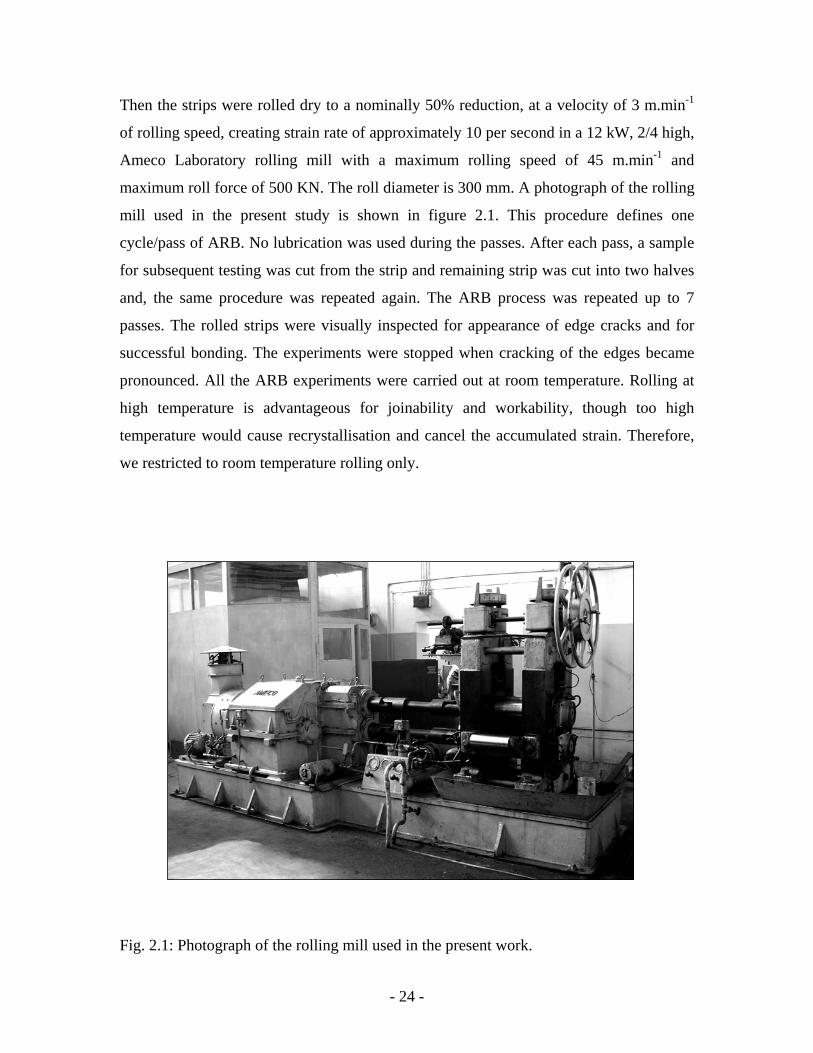
Then the strips were rolled dry to a nominally 50% reduction, at a velocity of 3 m.min-1
of rolling speed, creating strain rate of approximately 10 per second in a 12 kW, 2/4 high,
Ameco Laboratory rolling mill with a maximum rolling speed of 45 m.min-1 and
maximum roll force of 500 KN. The roll diameter is 300 mm. A photograph of the rolling
mill used in the present study is shown in figure 2.1. This procedure defines one
cycle/pass of ARB. No lubrication was used during the passes. After each pass, a sample
for subsequent testing was cut from the strip and remaining strip was cut into two halves
and, the same procedure was repeated again. The ARB process was repeated up to 7
passes. The rolled strips were visually inspected for appearance of edge cracks and for
successful bonding. The experiments were stopped when cracking of the edges became
pronounced. All the ARB experiments were carried out at room temperature. Rolling at
high temperature is advantageous for joinability and workability, though too high
temperature would cause recrystallisation and cancel the accumulated strain. Therefore,
we restricted to room temperature rolling only.
Fig. 2.1: Photograph of the rolling mill used in the present work.
- 24 -
2.3 Sample preparation for microstructural analysis
For the purpose of examining the bonding quality the samples from all the ARB
passes were cut, mounted and metallographically polished with successively finer grades
of emery papers and with silvet cloth using alumina powder of 0.3 micron grain size. The
final polishing was done using diamond paste. The polished samples were etched with
modified Keller’s reagent (2% HF, 3% HCl, 95% H2O). Microstructure investigations
were carried out on optical microscope of maximum 1500 magnification with image
analyzer for optical analysis.
Specimens for transmission electron microscopy were prepared from the
deformed samples of 1st, 3rd, 5th and 7th pass by cutting several small samples of 3 mm
diameter parallel to the rolling plane. The samples were mechanically thinned to a final
thickness 100 µm followed by ultrasonic cleaning and twin-jet electro-polishing using a
400 ml CH3OH + 40 ml HClO4 solution at –15 oC at a voltage of 20V. Then the samples
were examined in a PHILIPS CM 200 CX transmission electron microscope (TEM)
operated at 200kV and at 10-9 mbar vacuum.
Specimen for atomic force microscopy were prepared from 1st, 3rd, 5th and 7th
pass of ARB processed sheets. The samples were with 6 mm thickness and 3 mm width.
The longitudinal section of the samples was metallorgraphically polished following the
procedure as mentioned above. The polished samples were electro-polished using 700 ml
Ethanol + 200 ml perchloric acid + 100 ml glycerin solution at 20 V for 60 s. After the
electro-polishing step, samples of 5th and 7th pass were etched using dislocation etchant
(2 parts solution of 65 ml HCl + 35 ml HNO3 and 5 part solution 49 ml HF + 51 ml
water) at –15oC. The microstructure investigations were carried out on Atomic force
microscope model SPA 400 (Seiko Instrument Inc.). The dislocation etched samples
were also examined under scanning electron microscope so as to have an idea of the
joined interfaces. Dislocation etching is supposed to reveal the cracks more prominently.
The fractured surfaces generated after tensile testing give an idea of the fracture
mode of the samples as well the fracture mechanism. As the ARBed materials are made
of several layers, the fracture behaviour was important to study so as to have the idea of
- 25 -
interface behaviour during straining. Therefore, as-fractured surfaces were examined
under scanning electron microscope JSM 840 C.
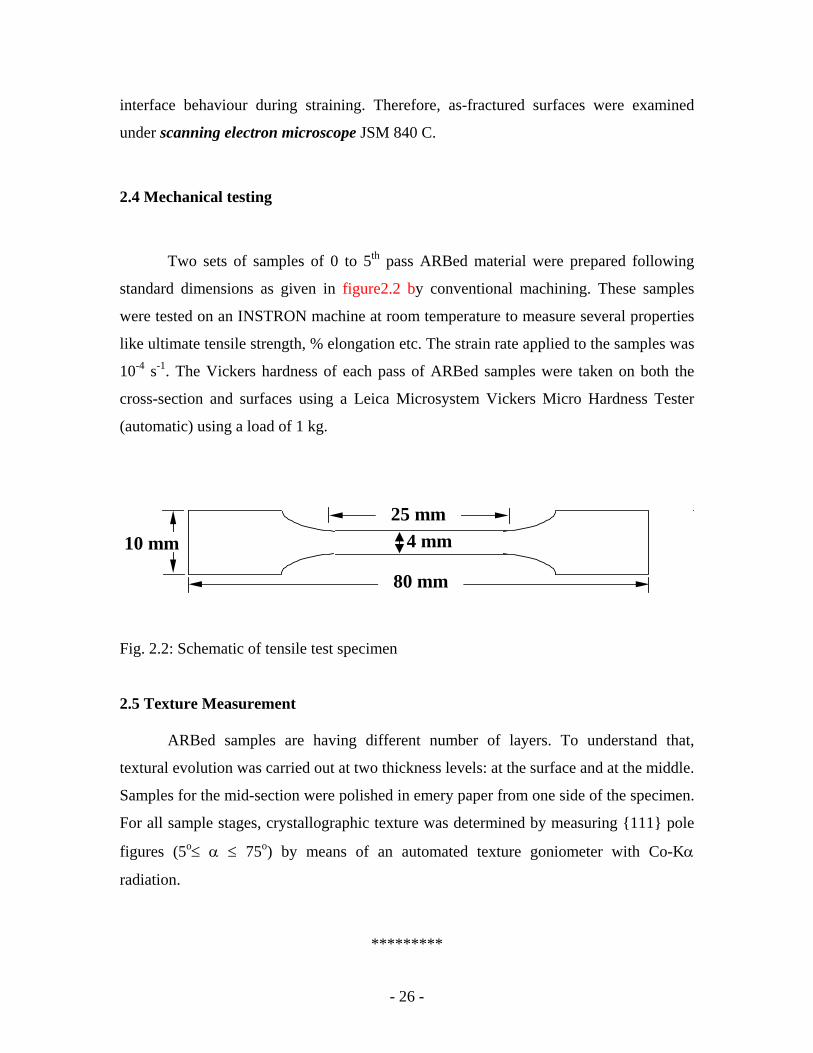
2.4 Mechanical testing
Two sets of samples of 0 to 5th pass ARBed material were prepared following
standard dimensions as given in figure2.2 by conventional machining. These samples
were tested on an INSTRON machine at room temperature to measure several properties
like ultimate tensile strength, % elongation etc. The strain rate applied to the samples was
10-4 s-1. The Vickers hardness of each pass of ARBed samples were taken on both the
cross-section and surfaces using a Leica Microsystem Vickers Micro Hardness Tester
(automatic) using a load of 1 kg.
4 mm
80 mm
25 mm 10 mm
Fig. 2.2: Schematic of tensile test specimen 2.5 Texture Measurement
ARBed samples are having different number of layers. To understand that,
textural evolution was carried out at two thickness levels: at the surface and at the middle.
Samples for the mid-section were polished in emery paper from one side of the specimen.
For all sample stages, crystallographic texture was determined by measuring {111} pole
figures (5o≤ α ≤ 75o) by means of an automated texture goniometer with Co-Kα
radiation.
*********
- 26 -
CHAPTER-III
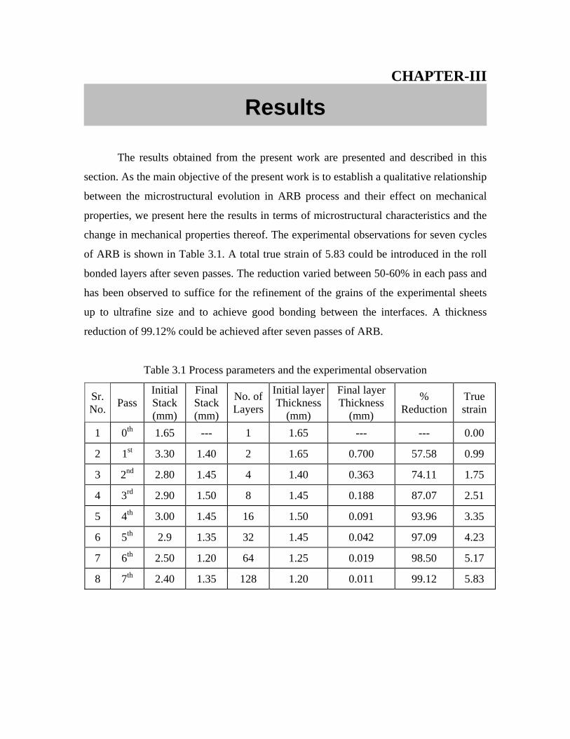
The results obtained from
section. As the main objective of th
between the microstructural evolu
properties, we present here the res
change in mechanical properties th
of ARB is shown in Table 3.1. A
bonded layers after seven passes. T
has been observed to suffice for th
up to ultrafine size and to achiev
reduction of 99.12% could be achie
Table 3.1 Process par
Sr. No. Pass
Initial Stack (mm)
Final Stack (mm)
NL
1 0th 1.65 ---
2 1st 3.30 1.40
3 2nd 2.80 1.45
4 3rd 2.90 1.50
5 4th 3.00 1.45
6 5th 2.9 1.35
7 6th 2.50 1.20
8 7th 2.40 1.35
Results
the present work are presented and described in this
e present work is to establish a qualitative relationship
tion in ARB process and their effect on mechanical
ults in terms of microstructural characteristics and the
ereof. The experimental observations for seven cycles
total true strain of 5.83 could be introduced in the roll
he reduction varied between 50-60% in each pass and
e refinement of the grains of the experimental sheets
e good bonding between the interfaces. A thickness
ved after seven passes of ARB.
ameters and the experimental observation
o. of ayers
Initial layerThickness
(mm)
Final layer Thickness
(mm)
% Reduction
True strain
1 1.65 --- --- 0.00
2 1.65 0.700 57.58 0.99
4 1.40 0.363 74.11 1.75
8 1.45 0.188 87.07 2.51
16 1.50 0.091 93.96 3.35
32 1.45 0.042 97.09 4.23
64 1.25 0.019 98.50 5.17
128 1.20 0.011 99.12 5.83
3.1 Interface characteristics
The optical and SEM micrographs of longitudinal cross-section of as ARBed
samples of different passes are shown in Fig. 3.1 and Fig. 3.2 respectively. This exercise
was undertaken to have an idea of the bonding characteristics and oxide entrapment
during bonding. The optical micrographs do not give a clear picture of bonding line
between the layers of samples. The interfaces are visible with discontinuous line in white
contrast. The discontinuous appearance of the interfaces creates confusion about the
quality of the bonds. So it is very difficult to comment on the quality of the bond whether
it is properly bonded or not. However, the number of discontinuous lines (i.e. interfaces
created) matched well with the expected number of interface in each pass. To avoid the
ambiguity created in examining the bond quality, the samples were dislocation etched (as
mentioned in the section 2.3). The scanning electron microscopy of dislocation etched
samples show a morphological change in comparison to the optical micrographs, due to
the fact that this etchant attacked preferentially at the highly strained areas or cracks. The
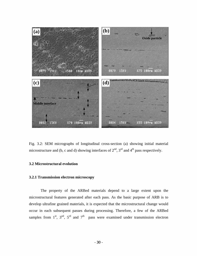
initial specimen (0th pass) showed a typical recrystallized structure with almost equiaxed
grains, and its mean grain size was ~ 5 µm (Fig. 3.2a). The interfaces introduced in the
second cycle, dividing four metallic layers, specimen is clearly seen in Fig. 3.2b. The
interfaces in the sample after 2nd pass reveal clearly that the bonding between layers is
not continuous. This indicates the presence of some oxide particle adhering to the cleaned
surface joined. The presence of such oxide particles restricts proper bonding between
metallic layers. However, two nascent surfaces are properly joined leaving no trace of
visible two layers, resulting in discontinuous interface. It has been observed and also
obvious from the figure that the interface created in the first pass (two outer interfaces) is
qualitatively better compared to that created in the first pass (middle interface). The
absence of oxide particle gives rise to a good bonding at the interface. After three cycles
of ARB (i.e. 8 layers), it becomes difficult to recognize the interface from the first pass
(Fig. 3.2c). And also, the bonding seems to improve at the interfaces created in earlier
passes. It is also observed that the size of oxide/debonded regions change in different
- 28 - 28
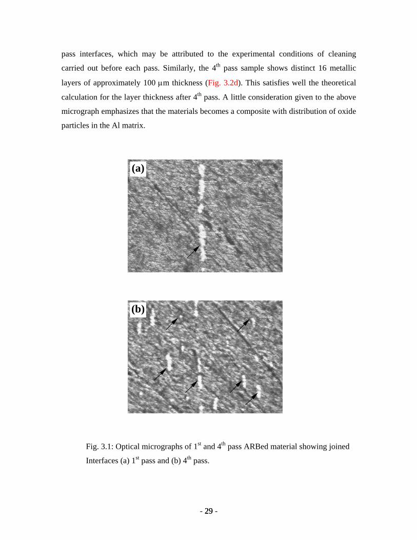
pass interfaces, which may be attributed to the experimental conditions of cleaning
carried out before each pass. Similarly, the 4th pass sample shows distinct 16 metallic
layers of approximately 100 µm thickness (Fig. 3.2d). This satisfies well the theoretical
calculation for the layer thickness after 4th pass. A little consideration given to the above
micrograph emphasizes that the materials becomes a composite with distribution of oxide
particles in the Al matrix.
(b)
(a)
Fig. 3.1: Optical micrographs of 1st and 4th pass ARBed material showing joined
Interfaces (a) 1st pass and (b) 4th pass.
- 29 - 29
Oxide particle
(d)
(b)
(c)
Middle interface
(a)
Fig. 3.2: SEM micrographs of longitudinal cross-section (a) showing initial material
microstructure and (b, c and d) showing interfaces of 2nd, 3rd and 4th pass respectively.
3.2 Microstructural evolution
3.2.1 Transmission electron microscopy
The property of the ARBed materials depend to a large extent upon the
microstructural features generated after each pass. As the basic purpose of ARB is to
develop ultrafine grained materials, it is expected that the microstructural change would
occur in each subsequent passes during processing. Therefore, a few of the ARBed
samples from 1st, 3nd, 5rd and 7th pass were examined under transmission electron
- 30 - 30
microscope to evaluate the structural development and mechanism of grain refinement
during this process.
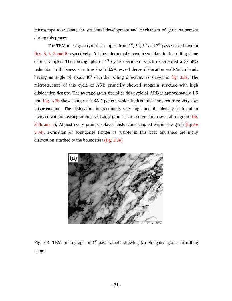
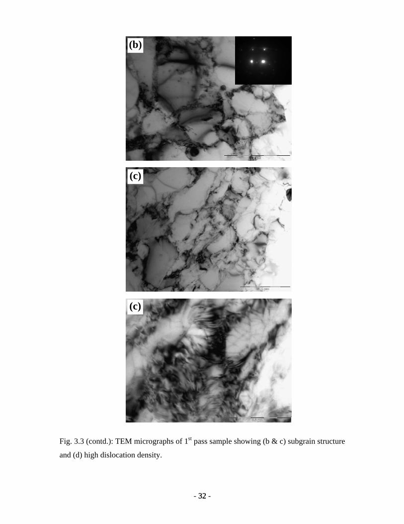
The TEM micrographs of the samples from 1st, 3rd, 5th and 7th passes are shown in
figs. 3, 4, 5 and 6 respectively. All the micrographs have been taken in the rolling plane
of the samples. The micrographs of 1st cycle specimen, which experienced a 57.58%
reduction in thickness at a true strain 0.99, reveal dense dislocation walls/microbands
having an angle of about 40o with the rolling direction, as shown in fig. 3.3a. The
microstructure of this cycle of ARB primarily showed subgrain structure with high
dilslocation density. The average grain size after this cycle of ARB is approximately 1.5
µm. Fig. 3.3b shows single net SAD pattern which indicate that the area have very low
misorientation. The dislocation interaction is very high and the density is found to
increase with increasing grain size. Large grain seem to divide into several subgrain (fig.
3.3b and c). Almost every grain displayed dislocation tangled within the grain (figure
3.3d). Formation of boundaries fringes is visible in this pass but there are many
dislocation attached to the boundaries (fig. 3.3e).
(a)
Fig. 3.3: TEM micrograph of 1st pass sample showing (a) elongated grains in rolling
plane.
- 31 - 31
(c)
(c)
(b)
Fig. 3.3 (contd.): TEM micrographs of 1st pass sample showing (b & c) subgrain structure
and (d) high dislocation density.
- 32 - 32
(e)
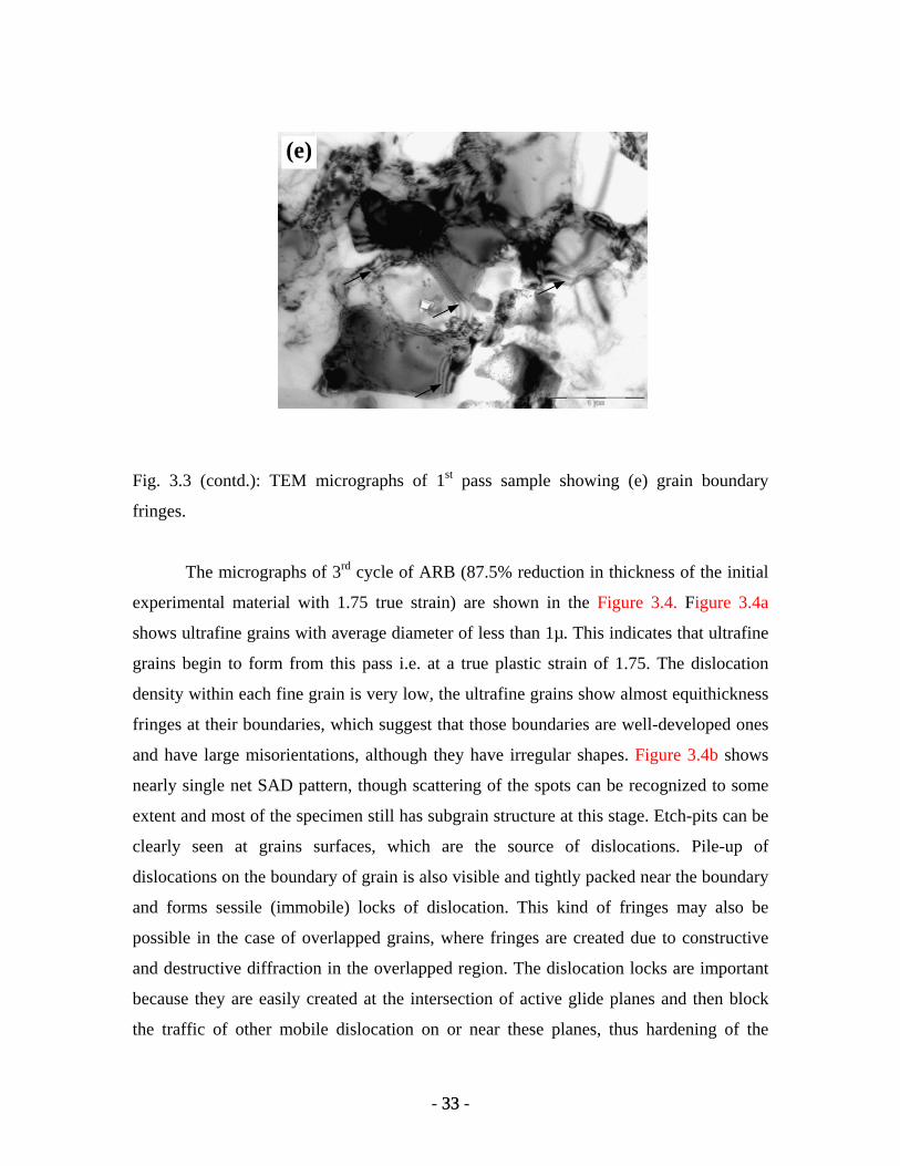
Fig. 3.3 (contd.): TEM micrographs of 1st pass sample showing (e) grain boundary
fringes.
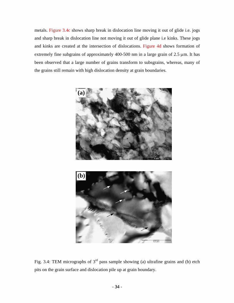
The micrographs of 3rd cycle of ARB (87.5% reduction in thickness of the initial
experimental material with 1.75 true strain) are shown in the Figure 3.4. Figure 3.4a
shows ultrafine grains with average diameter of less than 1µ. This indicates that ultrafine
grains begin to form from this pass i.e. at a true plastic strain of 1.75. The dislocation
density within each fine grain is very low, the ultrafine grains show almost equithickness
fringes at their boundaries, which suggest that those boundaries are well-developed ones
and have large misorientations, although they have irregular shapes. Figure 3.4b shows
nearly single net SAD pattern, though scattering of the spots can be recognized to some
extent and most of the specimen still has subgrain structure at this stage. Etch-pits can be
clearly seen at grains surfaces, which are the source of dislocations. Pile-up of
dislocations on the boundary of grain is also visible and tightly packed near the boundary
and forms sessile (immobile) locks of dislocation. This kind of fringes may also be
possible in the case of overlapped grains, where fringes are created due to constructive
and destructive diffraction in the overlapped region. The dislocation locks are important
because they are easily created at the intersection of active glide planes and then block
the traffic of other mobile dislocation on or near these planes, thus hardening of the
- 33 - 33
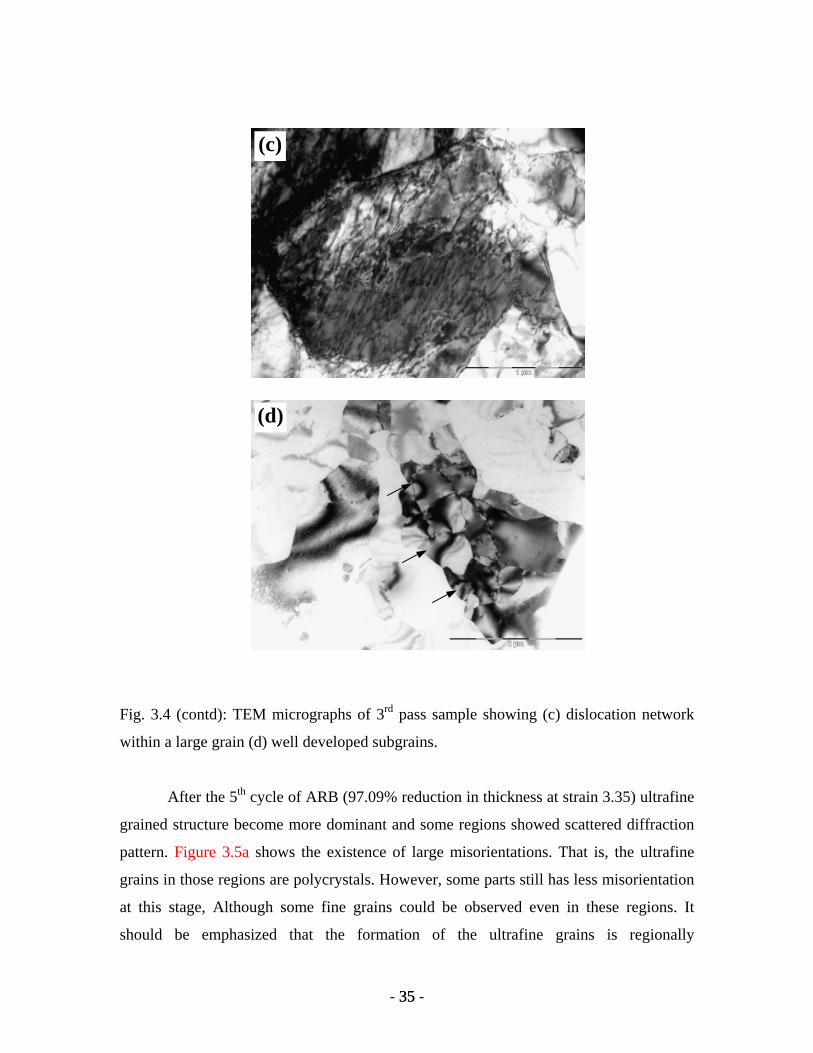
metals. Figure 3.4c shows sharp break in dislocation line moving it out of glide i.e. jogs
and sharp break in dislocation line not moving it out of glide plane i.e kinks. These jogs
and kinks are created at the intersection of dislocations. Figure 4d shows formation of
extremely fine subgrains of approximately 400-500 nm in a large grain of 2.5 µm. It has
been observed that a large number of grains transform to subsgrains, whereas, many of
the grains still remain with high dislocation density at grain boundaries.
(b)
(a)
Fig. 3.4: TEM micrographs of 3rd pass sample showing (a) ultrafine grains and (b) etch
pits on the grain surface and dislocation pile up at grain boundary.
- 34 - 34
(d)
(c)
Fig. 3.4 (contd): TEM micrographs of 3rd pass sample showing (c) dislocation network
within a large grain (d) well developed subgrains.
After the 5th cycle of ARB (97.09% reduction in thickness at strain 3.35) ultrafine
grained structure become more dominant and some regions showed scattered diffraction
pattern. Figure 3.5a shows the existence of large misorientations. That is, the ultrafine
grains in those regions are polycrystals. However, some parts still has less misorientation
at this stage, Although some fine grains could be observed even in these regions. It
should be emphasized that the formation of the ultrafine grains is regionally
- 35 - 35
inhomogenous in the highly strained materials. The fraction of the ultrafine grained
regions increases in 5th cycle, ultrafine grained structure become more dominant and
some regions showed highly scattered diffraction pattern. Grains with clear prismatic
boundary fringes can also be seen, which is evidence of massive dislocation annihilation.
Figure 3.5b shows the transformed low angle boundaries into high angle grain
boundaries. And also, the subgrains are free from dislocations. The low angle boundaries
generated in each pass seemed to change to high angle boundaries in subsequent passes.
After 7 cycles of ARB (reduction 99.12%) at true strain 5.83, the whole volume
of the material was filled with the ultrafine grains homogeneously (figure 3.6a).
However, the grain size did not show any significant decrease in size as compared to
earlier passes. It seems that some new mechanism is activated at this stage, which led to
fast dislocation annihilation reducing the dislocation density. Some contours within the
grains are also seen, which indicates high stress energy regions. Figure 3.6b show the
dislocation structure similar to that observed after the first pass i.e. dislocation segregated
at the grain boundaries. Before the 1st pass the grain size was around 5 µm, therefore,
high dislocations density could be observed within the grains. Whereas, the starting grain
size for the 6/7 pass was in the range of 500-800 nm, which would have led to faster
dislocation annihilation at the grain boundaries. The co-existance of dislocations and
dislocation loop debris was an evidence of dislocation generation and annihalation
occuring simultaneously at large plastic strains. Figure 3.6c shows fine subgrains of
around 400-500 nm size even after 7th pass. However, this behaviour was not very
dominant in 7th pass material compared to those observed in the 3rd and 5th pass.
- 36 - 36

(b)
(a)
Fig. 3.5: TEM micrographs of 5th pass showing (a) ultrafine grains with prismatic fringes
(b) subgrains completely free from dislocations.
- 37 - 37
(c)
(b)
(a)
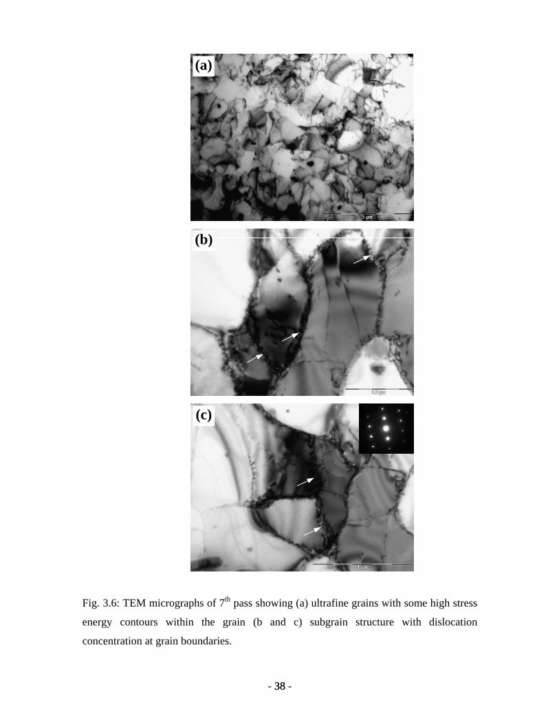
Fig. 3.6: TEM micrographs of 7th pass showing (a) ultrafine grains with some high stress
energy contours within the grain (b and c) subgrain structure with dislocation
concentration at grain boundaries.
- 38 - 38

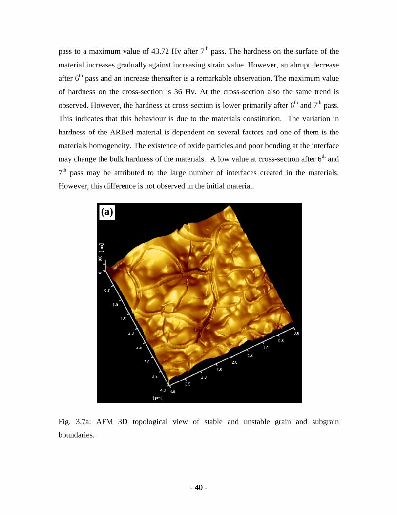
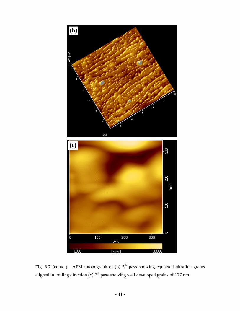
3.2.2 Atomic force microscopy
The AFM micrograph on the longitudinal cross-section after 5th and 7th cycle of
ARB samples are shown in figure 7 and 8 respectively. Figure 3.7a shows the
transformation process of grain into subgrain and vice-versa, the mixture of stable and
unstable boundaries can be seen clearly. Some grains in the figure are well developed
with stable and high misorientation and some grains are divided into subgrains with
unstable boundaries. The subboundaries coalesce to form a stable boundary. The
coalescence of subgrains is associated with “unraveling” of unstable subboundaries and
the passage of dislocations from them into nearest more stable sub-boundaries. An
indirect evidence to this is that the disappearance (unravelling) of a boundary usually
begins in direct contact with stable sub-boundaries. It is expected from the results of
these observations in AFM that unravelling boundaries are charecterised by a lower
dislocation density than stable ones. The cross slip plays an important part in forming
favourable conditions for coalescence of sub-grains. Figure 3.7b shows ultrafine grained
structure near the interface. The grain size in the interfacial region is expected to be
highly refined due to the fact that these regions experience a high shear strain during
ARB, compared to the middle of the layer. The average of grain size in the figure is 200
nm. The ultrafine grains completely converted into nanocrystalline grains in further
straining of the specimen, it can be seen in the AFM figure 3.7c, which have grains of
diameter about 177 nm. It is also found that the grain boundaries in the 7th pass specimen
are more stable than that of the 5th pass specimen.
3.3 Evaluation of Mechanical properties
3.3.1 Hardness measurements
The Vickers hardness on ARB processed samples was measured using a load of 1
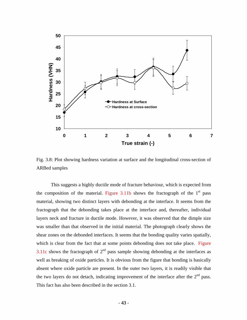
kg. Figure 3.8 shows the graphical presentation of the data of the hardness of the samples
from 0th to 7th cycle of ARB both at the longitudinal cross-section and the surface of the
ARBed samples. The surface hardness of the material increased from 17 Hv in the 0th
- 39 - 39
pass to a maximum value of 43.72 Hv after 7th pass. The hardness on the surface of the
material increases gradually against increasing strain value. However, an abrupt decrease
after 6th pass and an increase thereafter is a remarkable observation. The maximum value
of hardness on the cross-section is 36 Hv. At the cross-section also the same trend is
observed. However, the hardness at cross-section is lower primarily after 6th and 7th pass.
This indicates that this behaviour is due to the materials constitution. The variation in
hardness of the ARBed material is dependent on several factors and one of them is the
materials homogeneity. The existence of oxide particles and poor bonding at the interface
may change the bulk hardness of the materials. A low value at cross-section after 6th and
7th pass may be attributed to the large number of interfaces created in the materials.
However, this difference is not observed in the initial material.
(a)
Fig. 3.7a: AFM 3D topological view of stable and unstable grain and subgrain
boundaries.
- 40 - 40
(c)
(b)
Fig. 3.7 (contd.): AFM totopograph of (b) 5th pass showing equiaxed ultrafine grains
aligned in rolling direction (c) 7th pass showing well developed grains of 177 nm.
- 41 - 41
3.3.2 Tensile properties
The tensile properties have been evaluated for the samples from 0th to 5th pass
ARBed materials. Two samples from each pass were tested. The results showed
reproducible data for both the samples. All the tests were carried out at room temperature.
The results of tensile tests are shown in figure 3.9a & b showing engineering stress-strain
as well as true stress-strain diagrams, respectively. The major increase in strength is
observed after the first cycle of ARB. However, the relative increment in strength after
further ARB passes decreases and no difference was observed between 4th and 5th pass
ARBed materials. The characteristic nature of these plots show that the ultimate tensile
strength (UTS) and yield strength increases by 116% and 200% respectively after 5th pass
of ARB cycle. As the grain size decreases to an ultrafine scale, the strain hardening rate
decreases leading to a plunging tensile test curve . The necking starts soon after yielding.
This behaviour is also observed in the present tensile tests. The variation in strength and
elongation with the number of passes is shown in figure 3.10 for both the samples tested
for tensile strength. The values of the strength as well as elongation for both the samples
(sample-1 and sample-2) were close to each other indicating reproducibility of the results
with respect to the materials homogeneity. The plot shows that elongation for the initial
material varies between 31-34% compared to 4-6% in the case of ARBed materials. It is
therefore concluded that material strength increases with the lost of ductility during ARB
process. The decrease in elongation is very large after 1st pass ARB, however, there is not
much difference in elongation with further ARB steps. This indicates a pronounced loss
of formability during ARB. The details of these results have been discussed in chapter 4.
3.3.3 Tensile fracture behaviour
For further analysis of the bonding condition in tension and the mode of fracture,
the fracture surfaces of the as-ARBed samples after tensile tests are observed under the
scanning electron microscopy. The fracture surfaces are shown in figure 3.11. Figure
3.11a shows large size of dimples, with large voids, generated from the initial material.
- 42 - 42
10
15
20
25
30
35
40
45
50
0 1 2 3 4 5 6 7True strain (-)
Har
dnes
s (V
HN
)
Hardness at SurfaceHardness at cross-section
Fig. 3.8: Plot showing hardness variation at surface and the longitudinal cross-section of
ARBed samples
This suggests a highly ductile mode of fracture behaviour, which is expected from
the composition of the material. Figure 3.11b shows the fractograph of the 1st pass
material, showing two distinct layers with debonding at the interface. It seems from the
fractograph that the debonding takes place at the interface and, thereafter, individual
layers neck and fracture in ductile mode. However, it was observed that the dimple size
was smaller than that observed in the initial material. The photograph clearly shows the
shear zones on the debonded interfaces. It seems that the bonding quality varies spatially,
which is clear from the fact that at some points debonding does not take place. Figure
3.11c shows the fractograph of 2nd pass sample showing debonding at the interfaces as
well as breaking of oxide particles. It is obvious from the figure that bonding is basically
absent where oxide particle are present. In the outer two layers, it is readily visible that
the two layers do not detach, indicating improvement of the interface after the 2nd pass.
This fact has also been described in the section 3.1.
- 43 - 43
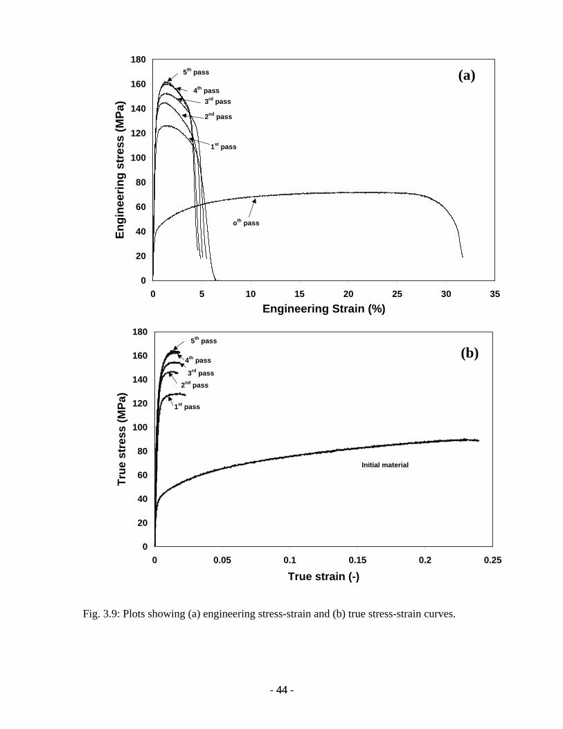
0
20
40
60
80
100
120
140
160
180
0 5 10 15 20 25 30 35Engineering Strain (%)
Engi
neer
ing
stre
ss (M
Pa)
1st pass
2nd pass
3rd pass4th pass
5th pass
oth pass
0
20
40
60
80
100
120
140
160
180
0 0.05 0.1 0.15 0.2 0.25
True strain (-)
True
str
ess
(MPa
)
Initial material
1st pass
2nd pass3rd pass
4th pass
5th pass
(b)
(a)
Fig. 3.9: Plots showing (a) engineering stress-strain and (b) true stress-strain curves.
- 44 - 44

60
80
100
120
140
160
180
0 1 2 3 4 5Number of passes
Stre
ngth
(MPa
)
0
5
10
15
20
25
30
35
40
Elon
gatio
n(%
)
sample-1-strengthsample-2-strengthsample-1-elongationsample-2-elongation
Fig. 3.10: Plot showing variation of strength and elongation with number of ARB passes.
Figure 3.11d shows the fracture surface after 2nd pass, indicating that the dimple
size is much smaller compared to that observed in the initial material. This is indicative
of the decrease in ductility and creation of large number of voids before necking. Figure
3.11e shows that the portion of debonded interface is highly strained away from a
strongly bonded area. This suggests that the bonding between surface does not take place
uniformly in terms of bond strength. The broken oxide particles are also seen in the
vicinity indicating debonding in that area of interface. It is therefore concluded that the
bond strength and the cleanliness of the surfaces before joining may play an important
role in determining the final strength of ARBed materials. Figure 3.11f show the
fractograph of 4th pass samples, clearly indicating the improvement in bond strength
brought forward from the previous passes. Large voids are created during tensile loading
where oxide particle existed at the interfaces. Finally, it is clear from the above results
- 45 - 45
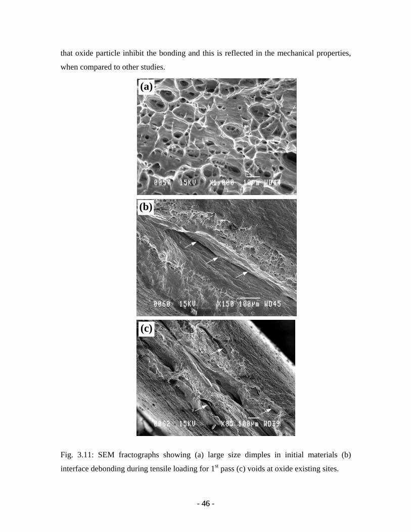
that oxide particle inhibit the bonding and this is reflected in the mechanical properties,
when compared to other studies.
(c)
(b)
(a)
Fig. 3.11: SEM fractographs showing (a) large size dimples in initial materials (b)
interface debonding during tensile loading for 1st pass (c) voids at oxide existing sites.
- 46 - 46
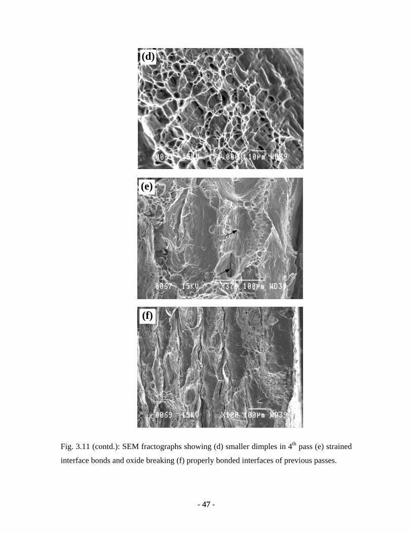
(f)
(e)
(d)
Fig. 3.11 (contd.): SEM fractographs showing (d) smaller dimples in 4th pass (e) strained
interface bonds and oxide breaking (f) properly bonded interfaces of previous passes.
- 47 - 47

3.4 Evolution of Texture
Texture measurement was carried out on the sample after 50% cold rolling.
Texture was measured on the mid-plane section. The corresponding {111} pole figure
has been presented in Fig.3.12.
Fig.3.12. Experimental {111} pole figure from mid-plane of 1st pass.
The texture components at this stage are mainly Brass {011}<112> and Cube
{001}<100> components. Increasing number of passes show evolution of new texture
components as well as diminution of exiting components. The overall texture intensity
has been found to vary with increasing number of passes. Fig.3.13 shows the {111} pole
figures for 2nd pass to 7th pass of ARBed material. After 2nd pass (fig. 3.13a), the surface
texture shows presence of Cu component {112}<111> and S component {123}<634>; at
the mid-plane section the brass is the major texture component apart from mild Cu and S
components. The texture intensity at the surface is similar to that of the mid-plane. {111}
pole figure for 3rd pass (fig. 3.13b)shows Brass, Cu and S component at both the sections;
only at the surface there is a slight indication of Cube-ND component. The intensity at
the surface is quite higher than the mid-plane section. After 4th pass (fig. 3.13c), there is a
complete change in the texture components at the surface; it is basically Cube-ND
component. At the mid-plane it is nearly same as that of at the mid-plane section after 3rd
pass.
- 48 - 48
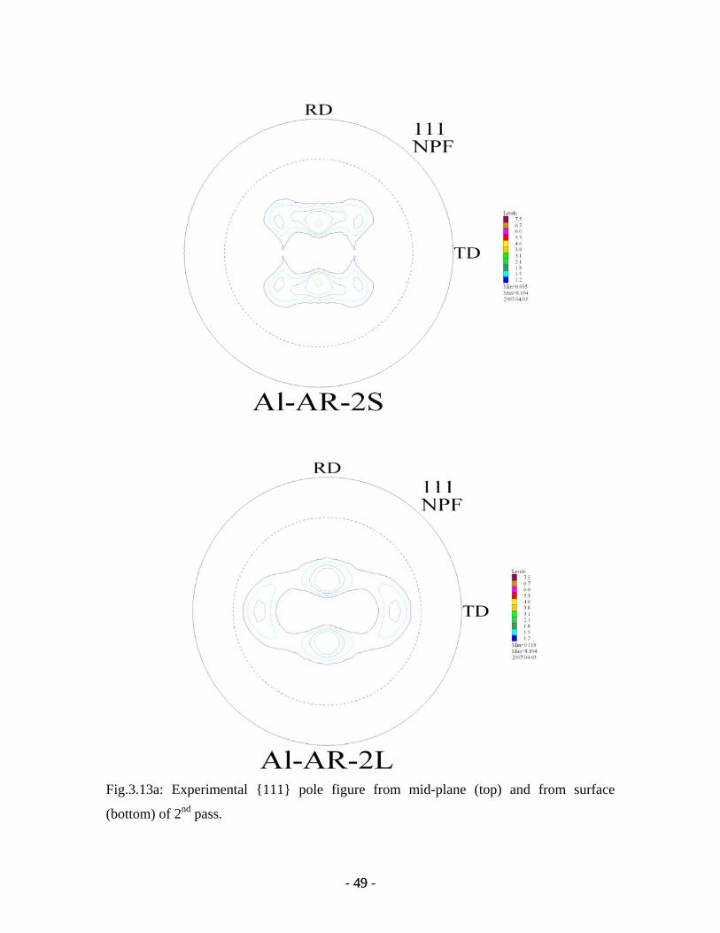
Fig.3.13a: Experimental {111} pole figure from mid-plane (top) and from surface
(bottom) of 2nd pass.
- 49 - 49
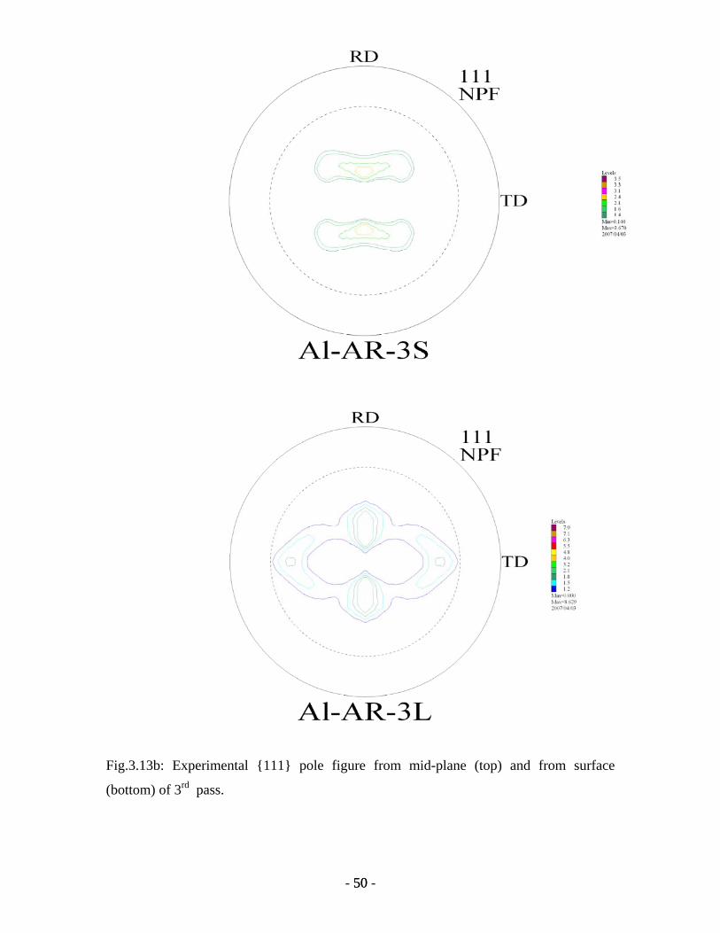
Fig.3.13b: Experimental {111} pole figure from mid-plane (top) and from surface
(bottom) of 3rd pass.
- 50 - 50
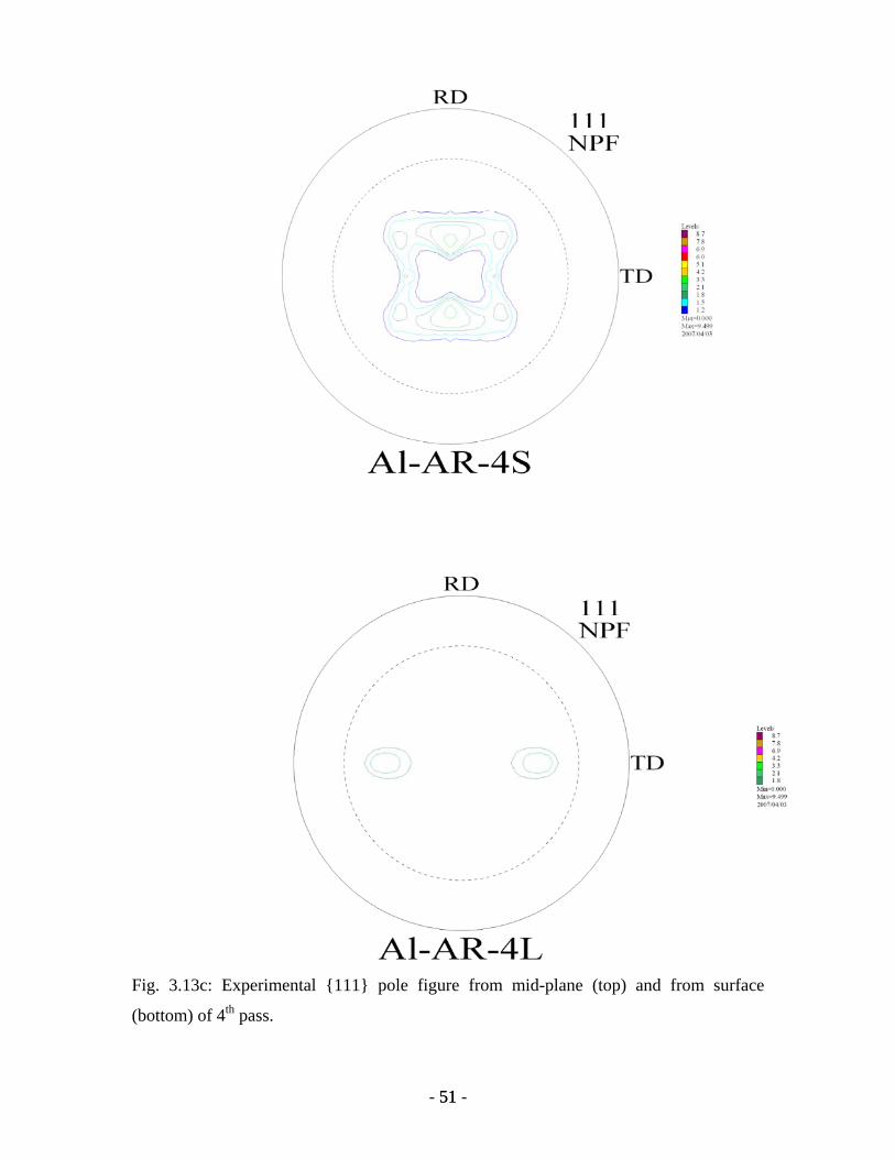
Fig. 3.13c: Experimental {111} pole figure from mid-plane (top) and from surface
(bottom) of 4th pass.
- 51 - 51
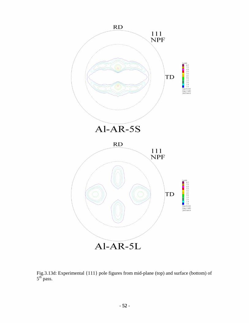
Fig.3.13d: Experimental {111} pole figures from mid-plane (top) and surface (bottom) of 5th pass.
- 52 - 52
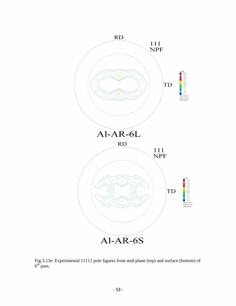
Fig.3.13e: Experimental {111} pole figures from mid-plane (top) and surface (bottom) of 6th pass.
- 53 - 53
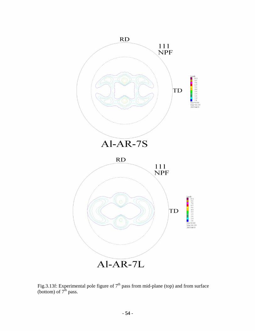
Fig.3.13f: Experimental pole figure of 7th pass from mid-plane (top) and from surface (bottom) of 7th pass.
- 54 - 54
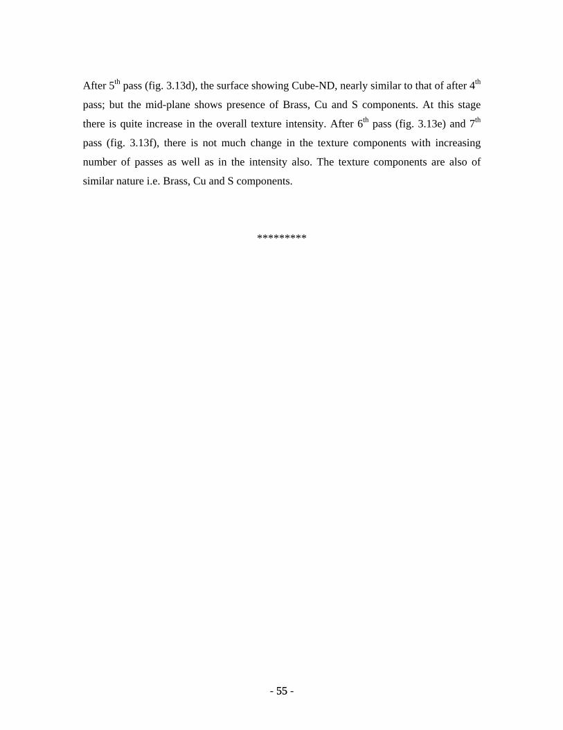
After 5th pass (fig. 3.13d), the surface showing Cube-ND, nearly similar to that of after 4th
pass; but the mid-plane shows presence of Brass, Cu and S components. At this stage
there is quite increase in the overall texture intensity. After 6th pass (fig. 3.13e) and 7th
pass (fig. 3.13f), there is not much change in the texture components with increasing
number of passes as well as in the intensity also. The texture components are also of
similar nature i.e. Brass, Cu and S components.
*********
- 55 - 55
CHAPTER-IV
Recently, severe plasti
attentions for the synthesis of u
major endeavour of materials
grained materials basically du
strength to weight ratio and i
materials synthesis has given
materials. There are several ro
and accumulative roll bonding
accumulative roll bonding proc
Al. Accumulative roll bonding
their microstructural analysis
thereof is discussed in light of
The results presented in
with sufficient strength could
It is practically very important
the bulk materials. If this pr
strength. Even pure materials,
this route to achieve better pe
associated with conventional a
the recent social demands of re
from the practicability point o
sophisticated instruments for p
the most popular ways of plast
easily carried out on materials,
Although the grain ref
attention to, the formation me
clarified to a satisfactory leve
Discussion
c deformation (SPD) processing has received considerable
ltrafine grained materials or nanocrystalline materials. The
scientists has been directed in the development of ultrafine
e to the promise of such materials in achieving higher
mproved physical properties. The top down approach of
way to SPD in the development of ultrafine grained
ute to incorporate severe plastic deformation in materials
technique is one of the variants of it. In the present study
ess has been employed to process commercial purity 1100
up to seven passes could be done in this study followed by
and mechanical property evaluation. The result obtained
process conditions and microstructural characteristics.
the previous chapter clearly showed that UFG aluminium
be readily obtained by accumulative roll bonding process.
because rolling is the most appropriate process to produce
ocess is applied to practical use, we could obtain high
without any alloying element addition, can be processed by
rformance. The complicated thermomechanical treatments
lloys can be easily obviated. This process can also address
cycling of materials. The process of ARB is also important
f view. Other processes such as ECAP and HPT require
rocessing. On the other hand, rolling technique is one of
ic working, and the detailed deformation analysis could be
compared to that obtained from other variants of SPD.
inement by large straining processes has been paid much
chanism of the sub-micron size grains has not yet been
l. The detailed study using ARB, now in progress, will
throw some light on the possible mechanisms of microstructural evolution during SPD.
The present study shwoed that the initial material strength of 70 MPa sufficiently
increases with the number of ARB cycles i.e. strain, and achieves a maximum value of
162 MPa after 5th cycles of ARB and at a strain of 4.23. The hardness of the material also
increases from 17 VHN to 43 VHN after 7th cycle of ARB and at true strain of 5.83. The
strengthening mechanism of the ARBed material of different passes are very well
interrelated with the changes in microstructure observed after corresponding cycles of
ARB. The strengthening of the materials up to 5th cycles is mainly due to work
hardening, since most of the materials showed conventional subgrain structures with
small misorientations and high dislocation densities. The strength is a function of applied
strain up to 5th cycle, which is directly related to the internal stress field created during
the straining process. In this study, it is found that the grain size decreases after each
cycle of the ARB i.e. strain. The effect of grain size on the material yield stress generally
followed the empirical Hall-Petch equation: yield stress is inversely proportional to the
root square of grain size for large grain sizes. The TEM micrographs of the material up to
5th pass generally shows the subgrains structure with high dislocation density. The
abundance of dislocation networks at the grain boundaries and within the grains of the
ARBed metals of 1st to 5th cycles of ARB provides obstacles to the movement of the free
dislocations in form of tightly packed sessile locks and complex intersection networks of
jogs (also called ledges) and sinks during plastic deformation, which in general, lead to
enhanced strength and hardness of the materials. Thus, from 1st to 5th cycles of straining,
the strain hardening results from mutual obstruction of dislocation glide and intersection.
The interaction of dislocations, sessile locks, and the interpenetration of one slip system
by another can leave dislocation jogs (ledges) behind. This theory of hardening due to
jogs (or forest of sessile dioslocations) was mentioned by Dieter (1986). The work
hardenning becomes more pronounced at the large grains because large grains have
enough space for significant numbers of dislocation intersections during deformation,
while in the smaller grains, dislocation deposit on opposite boundaries directly and result
in minimal hardening. This is due to the fact that smaller grain allow less time and less
volume for dislocation interaction. An analytical method for polycrystals with different
work hardening rates in different grain size samples was proposed by Thomson et al.
- 57 - 57
(1973) and successfully fit on the experimental results of the current work of severe
plastic deformation of the commercially pure aluminium alloy. The model was based on
Ashby’s idea about separating “statistically stored dislocations" accumulated during
deformation and “geometrically necessary dislocations” generated in order to maintain
continuty of the polycrystals. It indicates that work hardening rates should be higher in
larger grain sizes consistent with the current study. The basic description of this model is
that the hardness and strain near the boundary are different than in the grain centers.
Away from the boundary, dislocation population is dominated by statistically stored
dislocations, while in the boundary regions, different behavior is expected because grain
boundaries can act as dislocation sources and sinks. Moreover, high stress field is also
present near the grain boundaries. This should affect the local structure. For the larger
grain sizes, the statistically stored dislocation term is more important and has great
contribution to the yield stress, since the matrix stress is less than the boundary stresses at
small strains. These hardening differences arise from differences in statistical and
geometrical volume fractions as a function of grain size. A similar explanation of grain
size effects on strength due to varying work hardening between grain interiors and near
bounderies was used by Gray et al. (1999). However, work hardening behavior is
considered to depend on several factors, including deformation temperature, strain rate,
grain size, and texture. The texture of the as-ARBed specimen is shown in figure. The
influence of texture on work hardening, therefore, can be excluded as the principal
controlling variable.
In the present work, the hardness and the strength of the material achieved is less
than that achieved by other researchers by accumulative roll bonding of the same material
at room temperature (see Table 1.1 of chapter I). This difference in hardness and strength
of the material processed by same technique and at the same temperatrue is basically due
to the oxide entrapment during roll bonding. The presence of oxide particles on the
interfaces of the material after ARB is confirmed on characterising the dislocation etched
ARBed samples by scanning electron microscopy to get the idea of the interface and
fracture morphology after tensile testing. The SEM micrographs of 1st to 4th cycles of
ARB is sufficient to tell the story of effect of oxide particles on the hardness and strength
of the ARBed material. The oxide particles create serious debonding as well breakage.
- 58 - 58
The interface between layers become discontinuous leading to inferior bonding. The
discontinuous (non-uniform) presence of oxide particles seized the resistance capacity of
the material against the applied stress. As a result, the material fails before the expected
value of applied load. If experiments were carried out with some precaution to avoid the
oxide entrapment then the expected value of strength could be achieved comparable to
other studies. It can be also concluded from the cross-sectional hardness graph of the
material that hardness of the material is badly affected due to presence of oxide particles
at the interfaces. As the number of interfaces increases from 1st to 7th cycles, the content
of oxide particles also increases. This leads to unexpected low hardness values even after
large true strains are achieved in subsequent passes. The decrease in the hardness of the
material after 6th cycle may be due to the dynamic recovery of the material. The
activation energy for atomic diffusion decreases after a certain amount of incorporated
strain. This results in easy restoration by dislocation climb and cross-slips.
On the other hand, the evolution of the ultrafine grained structure must contribute
to the large strength after 5th cycles. However, the strength may saturated after 5th cycle at
which the whole volume in the sheet was filled with the ultrafine grains. The
strengthening in the transition region of micrograins to ultrafine grains between 5th to 7th
can be also explained by the increase in the volume fraction of the ultrafine grained
polycrystals. However, it has been ensured that the UFG polycrystals show the same
deformation mechanism as that in conventional materials, which can be explained by
dislocation theory.
The texture evolution during ARB showed that there are formation of brass,
copper and S component at varying intensity both at the surface and at the mid-plane
sections. This continued up to 3rd pass. After 4th pass, although the mid-plane section
remains same, the surface texture changes to cube-ND component. This indicates that at
this stage there is some changes in strain path at the surface. Presence of cube-ND was
observed after 5th pass at mid-section also. Subsequent passes show that again from cube-
ND, there is formation of brass, copper and S components after 6th and 7th pass. There
was not much change in the textural intensity after 5th pass onwards.
- 59 - 59
Therefore, the texture evolution in this material shows formation of brass, copper
and S components after 7th pass. It passes through a transition after 4th pass, which might
be due to additional strain component arising on the surface.
*********
- 60 - 60
The present work o
showed some interesting re
mechanical properties, whi
discussed in detail in chapte
drawn from this study.
Accumulative rol
achieve at true strain of 5.83.
The process was
the state of stress at that loca
The yield stress i
the experimental material. H
The hardness valu
The most pron
microstructural features were
Ultrafine grains, h
produced.
The ultrafine grain
the materials showed ultra-fi
The change in microstructure related very w
The texture evolutiat the mid-plane as well as at
Conclusions
n the accumulative roll bonding of commercial purity Al
sults in terms of microsctructural characteristics and the
ch is presented in chapter III. These results have been
r IV. In view of these, the following conclusions could be
l bonding of commercially pure Al sheets could be done to
limited by the occurrence of cracking of the edges, caused by
tion and improper cutting of the sheets before rolling.
ncreases with increasing strain and decreasing grain size of
owever, the ductility decreases to very low levels.
e doubled after 4 passes of ARB.
ounced change in the mechanical properties and the
observed to occur after the first cycle of ARB
aving a mean grain size in the range 1 µm, was successfully
s partially formed after 3rd cycle of ARB, and after 7th cycle,
ne grains of mean size 500-800nm.
mechanical properties corresponding with the change in ell
on shows formation of brass, copper and S components both the surface.
*********
- 61 - 61
In the cou
achieve the desire
attempted in the
section to elabora
taken care of in an
The dat
very important to
particles on the ma
The var
indentation to avo
For ten
influence of voids
The SA
that gives the simp
During
cracks at the edg
propagation.
As already
transformed it i
deformation meth
changed. Among t
temperatures, diffu
properties of the m
electrical and mec
Scope for future work
rse of experimentation, certain observations are made in order to
d objectives successfully. Due to the paucity of time, these could not be
present investigation. Therefore, an attempt has been made in this
te on the future possibilities in this area and remedies, which could be
y future endeavours.
a of tensile testing of the specimens of 6th and 7th cycle of ARB are
optimize the trends of strength and ductility and effects of oxide
terial after corresponding cycle of ARB.
iation in hardness of the material should be taken by micro- or nano-
id the influence of imperfection.
sile testing, very small size tensile samples should be used to avoid
that might adversely influence the mechanical response of the material.
D pattern should be taken from the regions having diameters of 3µm
le pattern either scattered or single net pattern.
the accumulative roll bonding process of the experimental material, the
es of the ARBed material should be trimmed to avoid further crack
mentioned, when a coarse grained material is severely deformed to
nto ultrafine grained/nanocrystalline materials by severe plastic
ods, the physical and mechanical properties of the material completely
hese properties the most interesting are the changes in Curie and Debye
sion and thermal coefficients. Another example is the change in elastic
aterial. These changes greatly influence the thermal, optical, magnetic,
hanical properties of the materials. Therefore these changes open the
- 62 - 62
door of new research for future researchers. By estimating the changes in physical and
mechanical properties of the material after ARB process, one can decide on the suitable
practical applications of ARBed materials. From the practical point of view, it is
important to acknowledge that recent studies have demonstrated very clearly a great
potential for the use of SPD processing and the incorporation of ARB in industrial
applications. There are very good reasons for believing that, in the relatively near future,
SPD processing will become established as the basis for the commercial production of
semi-products and products with UFG structures using a wide range of metals and alloys.
*********
- 63 - 63
S Anderson P M, Bingert A M Armstrong R W, Huges DJulia Weertman Symposium Asaro A R , Krysl P, Kad B Beygelzimer Y, VaryukhiZehetbauer M J, Valiev Weinheim, Germany: Wile Bird J E, Mukherjee A KRelation between propertie Chinh N Q, Szommer P, H Chokshi A K, Scripta Mate Chu HS, Liu KS, Yeh JW. Dieter G E, “Mechanical York, NY, 1986, pp. 231. Erb U, El-Sherik AM, Palu Furukawa M, Horita Z, La Gifkins R C, Langdon T G Gleiter H, In: Hansen N,polycrystals: MechanismsLaboratory; (1981) 15. Gleiter H, Prog Mater Sci. Gray G T, Chen S R, Vecc Hall E O, Proc Roy Soc B,
REFERENCE
, Misra A, Hirth J P, Acta Mater, 51 (2003) 6059.
A, Advanced Materials for the Twenty-First Centutry: The ed. Y.W. Chung, Warrendale, PA (1999) 409.
, Philos.Mag., 83 (2003) 733.
n V, Orlov D, Synkov S, Spuskanyuk A, Pashinska Y, In: R Z, editors. Nanomaterials by severe plastic deformation. y–VCH Verlag (2004) 511.
, Dorn J E, in: D G Brandon, A. Rosen (Eds.) Quantitative s and microstructure, Israel (1969) 255.
orita Z, Langdon T G, Adv Mater., 18 (2006) 34.
r., 23(1989) 1679.
Scripta Mater 2001;45:541.
Metallurgy”, 3rd edition, McGraw-Hill Book Company, New
mbo G, Aust KT, Nanostruct Mater, 2 (1993) 383.
ngdon TG, Metals Mater, 9 (2003) 141.
, J Inst Metals, 93 (1964–65) 347.
Horsewell A, Leffers T, Lilholt H, editors. Deformation of and microstructures. Roskilde, Denmark: Risø National
33 (1989) 223.
hio K S, Metal. Mater. Trans., 30A (1999) 1235.
64 (1951) 747.
- 64 - 64
Han B Q, Matejczyk D, Zhou F, Zhang Z, Bampton C, Lavernia E J, Metall Mater Trans, 35A (2004) 947. Hofmann D C, Vecchio K S, Mater Sci Eng, A402 (2005) 234. Horita Z, Furukawa M, Nemoto M, Langdon T G, Mater Sci Tech, 16 (2000) 1239. Huang J Y, Zhu Y T, Jiang H, Lowe TC, Acta Mater, 49 (2001) 1497. Hughes D A, Hansen N, Acta Mater., 45 (1997) 3871. Hughes D A, Hansen N, Acta Mater., 48 (2000) 2985. Koch C C, Sripta Mater., 49 (2003) 657. Koch CC, Cho YS, Nanostruct Mater, 1(1992) 207. Krallics G, Lenard J G, J. Mater.Proc.Tech, 152 (2004) 154. Langdon T G, Acta Metall. Mater, 42 (1994) 2437. Lapovok R, J. Mater. Sci., 40 (2005) 1. Lee S H , Saito Y, Tsuji N, Utsunomiya H, Sakai T, Scripta Mater, 46 (2002) 281. Li B L, Tsuji N, Kamikawa, Mater.Sci. Eng, A423 (2006) 331. Li J C M, Trans.Met.Soc., 227 (1963) 239. Liao X Z, Appl. Phys.Lett., 83 (2004) 3564. Liao X Z, Appl.Phys.Lett., 83 (2003) 5062. Liu Q, Huang X, Lloyd D J and Hansen N, Acta Mater., 50 (2002) 3789. Lu L, Science, 304 (2004) 422. Luton M J, Jayanth C S, Disko M M, Matras S and Vallone J, Mater Res Soc Symp Proc 132 (1989) 79. Meyers M A, Mishra A, Benson D J, Prog. Mater Sci, (2005) 443. Mishra R S, Ma ZY, Mater Sci Eng, R50 (2005) 1. Nabarro F R N, Report of a conference on strength of solids, the physical society, London, UK,1948,P.75 and C. Herring, J. Appli. Phys., 21 (1950) 437.
- 65 - 65
Nemoto M, Horita Z, Furukawa M, Langdon T G, Metals Mater, 4 (1998) 1181. Pande C S, Masumura M A and Armstrong R W, Nanostruct. Mater, 2 (1993) 323. Petch N J, J Iron Steel Inst, 174 (1953) 25. Rhodes C G, Mahoney M W, Bingel W H, Spurling R A, Bampton C C, Scripta Mater, 36 (1997) 69. Richert J, Richert M, Aluminium, 62 (1986) 604. Richert M, Liu Q, Hansen N, Mater Sci Eng, 260A (1999) 275. Saito Y, Tsuji N, Utsunomiya H, Sakai T and Hong R G, Scripta Mater, 39 (1998) 1221. Salishchev G A, Valiahmetov O R, Galeev R M, J Mater Sci, 28(1993) 2898. Segal V M, Reznikov V I, Drobyshevskiy A E, Kopylov V I, Russian Metall, 1 (1981) 99. Shin D H, Park J J, Kim Y S, Park K T, Mater Sci Eng, A328 (2002) 98. Sitdikov O, Sakai T, Goloborodko A, Miura H, Kaibyshev R, Mater Trans, 45 (2004) 2232. Smirnova N A, Levit V I, Pilyugin V I, Kuznetsov R I, Davydova L S, Sazonova VA, Fiz Met Metalloved, 61 (1986) 1170. Thompson A W, Baskes M I, Flangan W F, Acta Metall., 21 (1973) 1017. Tsuji N, Saito Y, Lee S H, Minamino H, Adv. Eng. Mater, 5 (2003) 338. Valiev R Z, Islamgaliev R K, Alexandrov I V, Prog Mater Sci, 45 (2000) 103. Valiev R Z, Korznikov A V, Mulyukov R R, Mater. Sci. Eng, A168 (1993) 141. Valiev R Z, Krasilnikov N A, Tsenev N K, Mater Sci Eng, 137A (1991) 35. Valiev R Z, Mulyukov R R, Ovchinnikov V V, Philos Mag Lett, 62(1990) 253. Valiev R Z, Nanostruct Mater, 3 (2004) 511. Valiev R Z, Nature Mater, 3 (2004) 511. Valieve R Z, Estrin Y, Horita Z, Langdom T G, .Zehetbauer M J, Zhu Y T, JOM April (2006) 33.
- 66 - 66

Valitov V A, Salishchev G A, Muhtarov H, Russian Metall, 3 (1994) 127. Varyutkhin V N, Beygelzimer Y Y, Synkov S, Orlov D, Mater Sci Forum, 503-504 (2006) 335. Vorhauer A, Mater. Sci. Forum, 503-504 (2005) 299. Wang J T, Mater Sci Forum, 503-504 (2006) 363. Wang Y, Chen M, Zhou F, Ma E, Nature, 419 (2002) 912. Witkin D B, Lavernia E J, Prog Mater Sci, 51(2006) 1. Xu C, J. Mater. Eng. Perform., 13 (2004) 683. Zehetbauer M, Acta Mat., 47 (1999) 1053. Zhao X, Jing T F, Gao Y W, Zhou J F, Wang W, Mater Lett, 58 (2004) 2335. Zhilyaev A P, Nurislamova G V, Kim B K, Baro M D, Szpunar J A, Langdon TG, Acta Mater, 51 (2003) 753. Zhu Y T, Liao X Z, Nature Materials, 39 (2004) 351. Zhu Y T, Jiang H, Huang J, Lowe TC, Metall Mater Trans, 32A (2001) 1559.
*********
- 67 - 67