Embed Size (px)
Citation preview

Construction Phase Plan
Rev: 4 Date: Nov 2017 Ref: STRU-H&S-FO-005 Page 1 of 32
© Amey plc UNCONTROLLED IF COPIED OR PRINTED
Project Number:
Project Title: M8 Junction 4 Whitburn Bridges Concrete Repairs (Superstructure Works)
Construction Phase Plan
M8 Junction 4 Whitburn Bridges Concrete Repairs (Superstructure
Works)
This document has been prepared in accordance with the requirements and recommendations of the
Construction (Design and Management) Regulations 2015
Name Signature Position Date
Prepared By: Principal
Contractor
Reviewed By: Principal
Contractor
Authorised for Issue: Principal
Contractor
Accepted on behalf
of Client
CDM Clients
Representative
Note: Please ensure that you have the final version of this document signed and authorised for issue PDF the signed document cover and add it to the electronic
version of this document as a Quality Assurance Record
redacted 11(2)
redacted 11(2)
Construction Phase Plan
Rev: 4 Date: Nov 2017 Ref: STRU-H&S-FO-005 Page 2 of 32
© Amey plc UNCONTROLLED IF COPIED OR PRINTED
Record of Revisions
Document History
Issue Date Purpose / Amendment
Authorisation and Acceptance Summary
Issue Date Prepared By Reviewed By Authorised By Status
Status
I For Information
D Draft
P Preliminary
R Review
A Approval
Construction Phase Plan
Rev: 4 Date: Nov 2017 Ref: STRU-H&S-FO-005 Page 3 of 32
© Amey plc UNCONTROLLED IF COPIED OR PRINTED
1.0 Description of Project
1.1 Project Description 1.2 Programming of the Project 1.3 Contacts: Details of Client, Principal Designers, Designers, Principal Contractor, Contractors and
other Consultants
1.4 Extent and Location of Existing Records and Plans
2.0 Management of Work
2.1 Management Structure and Responsibilities
2.2 Health and Safety Aims for the Project 2.3 Arrangements for Monitoring and Review
2.4 Site Specific Arrangements for: (i) Regular liaison between parties on site
(ii) Consultation with the workforce (iii) The exchange of design information between the client, designers, Principal Designer and
contractors on site (iv) Handling design changes during the project (v) The selection and control of contractors (vi) The exchange of health and safety information between contractors (vii) Site security (viii) Site induction
(ix) On site training (x) Welfare facilities and first aid
(xi) The reporting and investigation of accidents and incidents including near misses (xii) The production and approval of risk assessments and written systems of work
2.5 Site Rules (including drug and alcohol policy) 2.6 Fire and emergency procedures
3.0 Arrangements for Controlling Significant Site Risks
3.1 Safety Risks, including (i) Delivery and removal of materials and work equipment (ii) Dealing with services (iii) Accommodating adjacent land use (iv) Stability of structures whilst carrying out construction work (v) Preventing falls
(vi) Work with or near fragile materials (vii) Control of lifting operations
(viii) Maintenance of plant and equipment (ix) Work on excavations and work where there are poor ground conditions
(x) Work on wells, underground earthworks and tunnels (xi) Work on or near water where there is a risk of drowning (xii) Work involving diving (xiii) Work in a caisson or compressed air working (xiv) Work involving explosives (xv) Traffic routes and segregation of vehicles and pedestrians (xvi) Storage of materials and work equipment (xvii) Any other significant safety risks
3.2 Health Risks, including: (i) The removal of asbestos (ii) Dealing with contaminated land
Construction Phase Plan
Rev: 4 Date: Nov 2017 Ref: STRU-H&S-FO-005 Page 4 of 32
© Amey plc UNCONTROLLED IF COPIED OR PRINTED
(iii) Manual handling
(iv) Use of hazardous substances, particularly where there is a need for health monitoring (v) Reducing noise and vibration (vi) Work with ionising radiation (vii) Exposure to UV radiation (from the sun) (viii) Any other significant health risks
4.0 The Health and Safety File
4.1 Format 4.2 Arrangements for the collection and gathering of information 4.3 Storage of information
Appendices
A Project Information
Location of A & E Emergency Procedures
Fire Management Plan Traffic Management Plan Programme of Works
B Additional Organograms / Competency Evidence C Amey Policies D Risk Assessments / Method Statements
E Site Inductions F Hazardous Materials / COSHH Assessments
G Product Data Sheets H Drawings and Information
• Statutory Undertakers • Designers Drawings • PC’s Drawings • Contractor Drawings
I Structural Principals and Test Certification J F10
K Pre Construction Information
Construction Phase Plan
Rev: 4 Date: Nov 2017 Ref: STRU-H&S-FO-005 Page 5 of 32
© Amey plc UNCONTROLLED IF COPIED OR PRINTED
1. Description of Project
1.1 Project Description
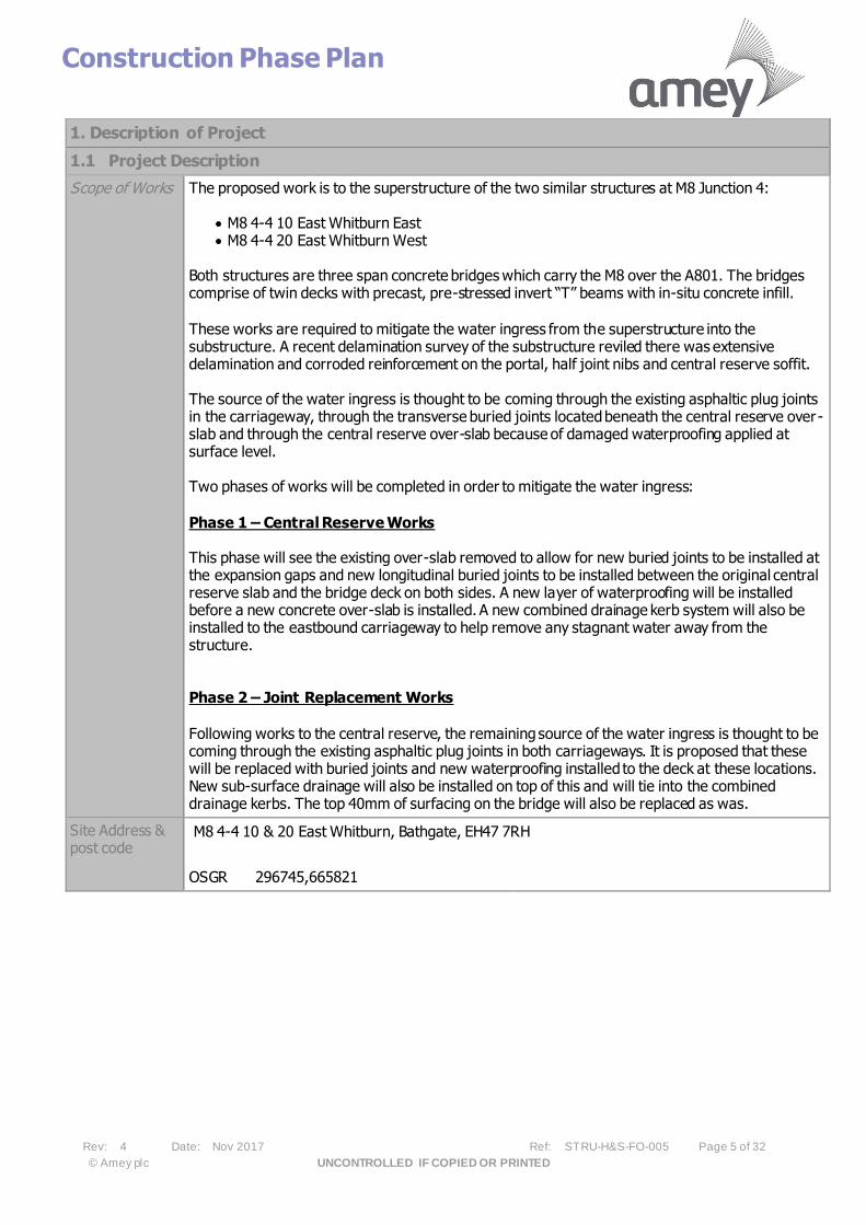
Scope of Works The proposed work is to the superstructure of the two similar structures at M8 Junction 4:
• M8 4-4 10 East Whitburn East • M8 4-4 20 East Whitburn West
Both structures are three span concrete bridges which carry the M8 over the A801. The bridges comprise of twin decks with precast, pre-stressed invert “T” beams with in-situ concrete infill.
These works are required to mitigate the water ingress from the superstructure into the substructure. A recent delamination survey of the substructure reviled there was extensive delamination and corroded reinforcement on the portal, half joint nibs and central reserve soffit. The source of the water ingress is thought to be coming through the existing asphaltic plug joints in the carriageway, through the transverse buried joints located beneath the central reserve over-slab and through the central reserve over-slab because of damaged waterproofing applied at surface level. Two phases of works will be completed in order to mitigate the water ingress:
Phase 1 – Central Reserve Works This phase will see the existing over-slab removed to allow for new buried joints to be installed at the expansion gaps and new longitudinal buried joints to be installed between the original central reserve slab and the bridge deck on both sides. A new layer of waterproofing will be installed before a new concrete over-slab is installed. A new combined drainage kerb system will also be installed to the eastbound carriageway to help remove any stagnant water away from the structure. Phase 2 – Joint Replacement Works
Following works to the central reserve, the remaining source of the water ingress is thought to be coming through the existing asphaltic plug joints in both carriageways. It is proposed that these will be replaced with buried joints and new waterproofing installed to the deck at these locations. New sub-surface drainage will also be installed on top of this and will tie into the combined drainage kerbs. The top 40mm of surfacing on the bridge will also be replaced as was.
Site Address & post code
M8 4-4 10 & 20 East Whitburn, Bathgate, EH47 7RH
OSGR 296745,665821
Construction Phase Plan
Rev: 4 Date: Nov 2017 Ref: STRU-H&S-FO-005 Page 6 of 32
© Amey plc UNCONTROLLED IF COPIED OR PRINTED
1. Description of Project
1.1 Project Description
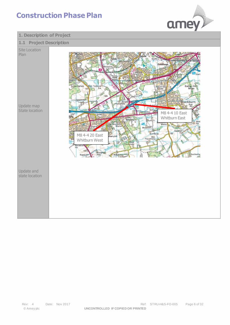
Site Location Plan
Update map State location
Update and state location
M8 4-4 10 East
Whitburn East
M8 4-4 20 East
Whitburn West

Construction Phase Plan
Rev: 4 Date: Nov 2017 Ref: STRU-H&S-FO-005 Page 7 of 32
© Amey plc UNCONTROLLED IF COPIED OR PRINTED
1.2 Programming of the Project
Time Allowed by Client (Mobilisation Period in weeks) 3 months
Site Works Start Date 16/09/2019 Duration of Works (weeks) 12 weeks
Maximum number of people at work on site at one time
?10 Planned number of Contractors 2
Working Hours 07:00-19:00, but will need back shift rotation for Joints work
Construction Phase Plan
Rev: 4 Date: Nov 2017 Ref: STRU-H&S-FO-005 Page 8 of 32
© Amey plc UNCONTROLLED IF COPIED OR PRINTED
Proposed Phasing Traffic management will be set-up on the M8 before any works are completed on site. The first phase will see closure of lane 1 and lane 2 in the eastbound carriageway and lane 2 of the westbound carriageway for 5 weeks. A temporary
traffic barrier will be installed adjacent to the structures to protect the bottom central reserve slab once exposed. Phase 1 – Central Reserve Works The work stages for this phase are as follows: • Remove existing VRS and carefully break out existing central reserve top
slab by saw cutting and hand breakers. • Perform post push-pull test on central reserve run-on slabs. • Remove kerbs.
• Apply 45° chamfered edge to bridge deck in central reserve and make repairs to bottom concrete slab.
• Install Type 1 buried joints along longitudinal joints between bottom slab and bridge deck.
• Install Type 1 buried joints transversely from carriageway to central reserve. • Prepare bottom slab and deck to receive waterproofing. • Apply waterproofing and membrane to the repaired slab and down back of
kerbs concrete haunching. • Install new combined kerb drainage system at the central reserve in the
eastbound carriageway and new concrete kerbs in the westbound carriageway.
• Tie-in new combined kerb drainage system with existing gully’s. • Place in reinforcement for new concrete slab. • Install formwork and cast new reinforced slab. • Apply saw-cuts to slab and fill with polysulphide sealant. • Install new N2 W3 flexbeam barrier and tie into existing barrier system. Update: Works at Joints have been added in Phase 1 from Phase 2 to increase the Efficiencies of the work site and accelerate the programme to reduce the duration of works to members of public. Eastbound Lane 2 and ½ Lane 1 were excavated, concreted up, and patched awaiting buried joint works at the end by Tarmac. Westbound had ½ Lane 2 completed in the same arrangement as
Eastbound. The exposed joints then will have drainage inserted where it can fit, but some area do not have the depth to insert Combined drainage so alternates have been looked at to try and install drainage assistance for the joint, with EB being particularly shallow. WB joints alolow more tolerance. Joints being based and temporary surfaced to allow switch and final buried joint treatment. Phase 2A and B – Joint Replacement The work stages for this phase are as follows:
Joint Replacement Eastbound Carriageway
• Install eastbound lane closure between J4 off and on slip. • Install debris netting to eastbound carriageway parapets. • Remove 40mm of HRA surfacing over full bridge deck.
• Remove eastbound APJ’s. • Repair bridge deck beneath joint. • Install buried joints • Waterproofing full length of joint base and 150mm down back of joints at the
abutments.
Construction Phase Plan
Rev: 4 Date: Nov 2017
© Amey plc UNCONTROLLED IF COPIED OR PRINTED
• Install sub-surface drainage and tie into new combined kerb drainage system. • Reinstate 40mm of HRA surfacing over full bridge deck.
• Remove debris netting and traffic management.
Joint Replacement Westbound Carriageway
• Install westbound full closure between J4 off and on slip. • Install debris netting to westbound carriageway parapets. • Remove 40mm of HRA surfacing over full bridge deck. • Remove westbound APJ’s.
• Remove kerbs to south of carriageway. • Repair bridge deck beneath joint. • Install buried joints. • Waterproofing full length of joint base and 150mm down back of joints at the
abutments. • Install new combined kerb drainage system. • Install sub-surface drainage and tie into new combined kerb drainage system.
• Reinstate 40mm of HRA surfacing over full bridge deck. • Remove debris netting and traffic management.
Update: Phase 2A of the works, changed from Contraflow to Lane 2 Running in either direction, with Traffic lights continuing at each slip. This was to catch the overlap from Phase 1 of the joints, with Eastbound joints overlap proving to improve productivity with the Hard shoulder Running on first phase to get completed earlier
and removed on WC 11th November 2019 (Sat). Westbound only running with work on WC 18th November 2019. Phase 2B will only involve WB Lane Closures, with Traffic being pushed to Hard shoulder Running for a maximum duration of 4 days to complete the joints in the centre, due to the weakness of the current hard shoulder in the area. Works were put in place to upgrade current weak points and upgrade gullies to allow the hard shoulder to satisfactorily cope with the short duration of Traffic running. Phase 2B will have concrete repairs, waterproofing in overlap section as in previous movements. WB will be removed by Sunday 24th November, ready for Deck Resurfacing along with EB on 23rd November 2019.
1.3 Contacts: Details of Client, Designers, Principal Designer and other Consultants
Client Contact
Position
Tel
Fax
Principal Designer
Contact
Position
Tel
Fax
Scheme Designer Contact
Position
Tel
redacted 11(2) redacted 11(2)


Construction Phase Plan
Rev: 4 Date: Nov 2017 Ref: STRU-H&S-FO-005 Page 11 of 32
© Amey plc UNCONTROLLED IF COPIED OR PRINTED
1.4 Extent and Location of Existing Records and Plans
Other Available Information ✓ Public Utility drawings included in Appendix E.
Buildings / Structures to be refurbished, altered or demolished
Yes No Comments
Architectural ✓
Structural ✓
Mechanical and/or electrical ✓
Public Health ✓
Location of existing services, particularly those that are concealed
Statutory Undertaker Not Present
Over Head
Under ground
Comments
Electricity Networks
400kV ✓
Overhead transmission lines are also located approximately 250m east of structure M8 4-4 10 Whitburn East. As the works are only within close proximity of the bridge decks these should not affect the works.
133kV ✓
66kV ✓
33kV ✓ A 33kV underground cable passes to the East of the Whitburn East bridge. Details of cables can be found in Appendix E. SPEN used CAT scanner on bridge deck and was confident there were no cables within the bridge deck and that they run under the M8 at the local road level. Trial pits to be carried out in
verges to confirm that the cable is not at the M8 level.
11kV ✓
240 / 415Volts ✓
Water (Foul and Potable)
Public Foul ✓
Pressurised Foul ✓
Public Combined Gravity ✓
Pressurised Combined ✓
Culverted Watercourse ✓ Water Main ✓
Aqueduct ✓
Communications
BT Openreach ✓
Virgin Media ✓
National Grid (SGN) Gas
LP Mains ✓
MP Mains ✓
IP Mains ✓
LHP Mains ✓
NHP Mains ✓
Fuel Pipelines
Construction Phase Plan
Rev: 4 Date: Nov 2017 Ref: STRU-H&S-FO-005 Page 12 of 32
© Amey plc UNCONTROLLED IF COPIED OR PRINTED
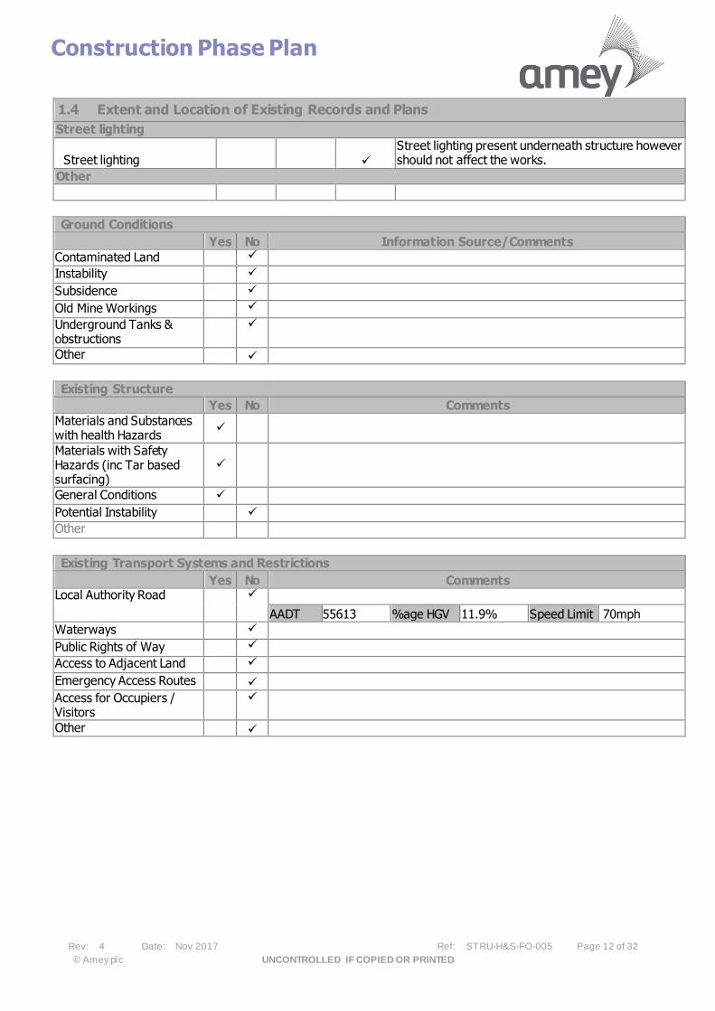
1.4 Extent and Location of Existing Records and Plans
Street lighting
Street lighting ✓
Street lighting present underneath structure however should not affect the works.
Other
Ground Conditions
Yes No Information Source/Comments
Contaminated Land ✓
Instability ✓
Subsidence ✓
Old Mine Workings ✓
Underground Tanks & obstructions
✓
Other ✓
Existing Structure
Yes No Comments
Materials and Substances with health Hazards
✓
Materials with Safety Hazards (inc Tar based surfacing)
✓
General Conditions ✓
Potential Instability ✓
Other
Existing Transport Systems and Restrictions
Yes No Comments Local Authority Road
✓
AADT 55613 %age HGV 11.9% Speed Limit 70mph
Waterways ✓
Public Rights of Way ✓ Access to Adjacent Land ✓
Emergency Access Routes ✓
Access for Occupiers / Visitors
✓
Other ✓
Construction Phase Plan
Rev: 4 Date: Nov 2017 Ref: STRU-H&S-FO-005 Page 13 of 32
© Amey plc UNCONTROLLED IF COPIED OR PRINTED
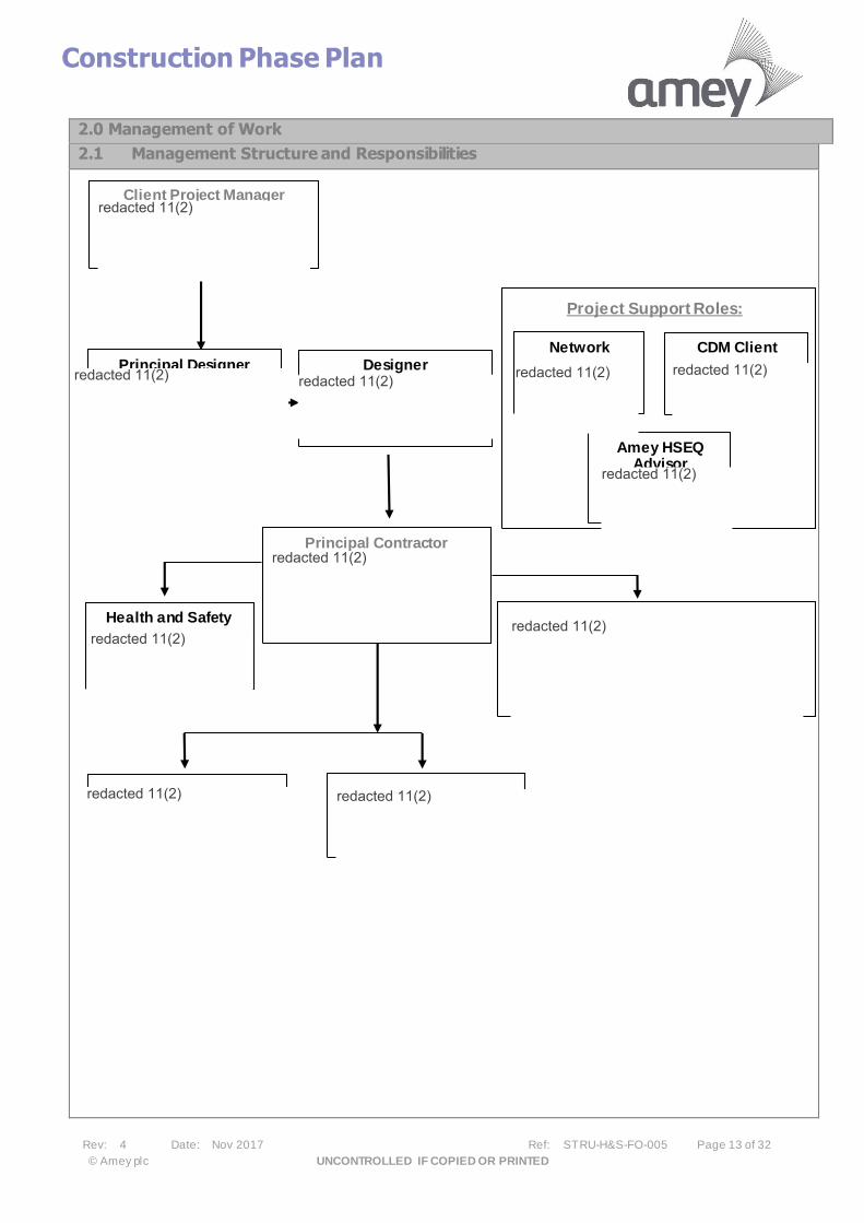
2.0 Management of Work
2.1 Management Structure and Responsibilities
Network CDM Client Principal Designer Designer
Amey HSEQ Advisor
Project Support Roles:
Health and Safety
Client Project Manager
Principal Contractor
redacted 11(2)
redacted 11(2) redacted 11(2)
redacted 11(2)
redacted 11(2)
redacted 11(2)
redacted 11(2)
redacted 11(2)redacted 11(2)
redacted 11(2)redacted 11(2)

Construction Phase Plan
Rev: 4 Date: Nov 2017 Ref: STRU-H&S-FO-005 Page 14 of 32
© Amey plc UNCONTROLLED IF COPIED OR PRINTED
Responsibilities of Site Management and Operational Staff
Project Director • Ensure that suitable and sufficient resources are available to implement the requirements of this plan • Assign key responsibilities to individuals to help deliver the Construction Phase Plan • Review and approval of the Construction Phase Plan, ensuring it’s requirements are implemented • Approve Sub-Contractors and Suppliers.
HSEQ Adviser
• Provide professional advice with regards to health, safety and environmental issues • Monitor Health and Safety performance
Principal Contractor
• Ensure the requirements of this plan are implemented with regard to quality, health & safety and environmental issues
• Liaise with the transport manager to ensure proper servicing and maintenance of vehicles, plant and equipment.
• Investigating incidents and accidents
• Ensure weekly Health and Safety audits of the site are carried out • Review and approve risk assessments • Ensure Environmental and Health and Safety issues are considered to minimise risks on site and impact
once construction is complete • Prepare this plan ready for review and approval, and ensure it is updated and further developed as
required • Communicate the contents of this plan to Site Supervisors
Site Supervisor
• To ensure that work carried out under their supervision complies with the requirements of this plan and Amey’s procedures
• Carry out site inductions and work box talks • Ensure that no work is undertaken unless a suitable risk assessment has been carried out • Prepare risk assessments where none exist • Collate HAV record sheets, if required
• Receive and process variation orders Contractor’s Operatives
• Ensure that safety of all personnel and public is top priority • Carry out work activities in a safe manner in accordance with the inductions received and Amey’s
procedures • Ensure that, HAV record sheets, daily vehicle checks and where appropriate near miss forms are
completed and passed to the site supervisor.
• Ensure cleanliness and tidiness of the site.
Construction Phase Plan
Rev: 4 Date: Nov 2017 Ref: STRU-H&S-FO-005 Page 15 of 32
© Amey plc UNCONTROLLED IF COPIED OR PRINTED
2.2 Health and Safety Aims for the Project
We adopt a Target Zero policy to accidents/incidents and have the buy in from all staff to Make It Happen and help achieve our objective of Keeping People Safe Every Day and it is our aim to: • Ensure that whilst conducting our activities, we do so in a safe manner without accident or incident • Achieve a sustainable working time ethos throughout the business to support the health & safety of all our
people • Achieve a culture of safe and responsible operation of road vehicles and associated equipment • Reduce the impact that others have on the safety of our people by ensuring compliance with CDM
Regulations by both internal and external parties • Encourage further environmental awareness and improve sustainability of our operations and reduce
pollution Initial safety goals will be reviewed by Operational Safety Advisor/Operations Manager
2.3 Arrangements for Monitoring and Review:
Inspections & Audits by Client All parties will be checked for competency and awareness of CDM 2015 - See Appendix B That communication, coordination and cooperation is taking place That sufficient time and resource has been allocated That suitable welfare is present
Inspections by Principal Contractor
The Safety Advisor will conduct a periodic inspection and report any compliance issues in a written format to the CDM Client Representative. This statement shall also be presented to the Site Manager, at the time of the Inspection, who will delegate actions to rectify all non-conformances to a given timetable. The frequency of these inspections will be dependent on risk and will change dependent on scores, accidents
and perceived risk. The Site Supervisor will undertake a daily inspection of a work activity method statement and highlight any items that do not comply.
Audits by Contractors
Contractors are to audit their work as detailed in the vetting form and copy this information to the Site Manager of the work location. The frequency and effectiveness of Inspections and Audits will be reviewed at the ongoing Safety Review Meetings.
2.4 Site Specific Arrangements for:
(i) Regular liaison between parties on site Regular progress meetings shall be held between the Principal Contractor, Designer and Contractors. The Principal Designer shall attend as and when required.
(ii) Consultation with the workforce
The Site Supervisor will ensure that all members of the team are aware of any changes to the programme, design or procedures. The Contractors Site Supervisor shall undertake work box talks with the works team on a weekly basis when required. Work box talks are to be added to Appendix E of this Plan. Individuals are invited to speak with any member of the Site Management Team if they have any suggestions, concerns, or questions relating to Health & Safety in the workplace. Contractor arrangements to be confirmed
Construction Phase Plan
Rev: 4 Date: Nov 2017 Ref: STRU-H&S-FO-005 Page 16 of 32
© Amey plc UNCONTROLLED IF COPIED OR PRINTED
(iii) The exchange of design information between the client, Principal Designer, designers and contractors on site All design queries to be directed through the Principal Contractor to appropriate designer and Principal
Designer.
(iv) Handling design changes during the project Any design changes shall be discussed at the weekly Design progress meetings and any new drawings or documentation will be issued through the Principal Contractor for distribution. New and/or amended drawings will be recorded on the register contained in Appendix H. Risk assessments and methods of work will be re-assessed on the issue of revised drawings or documents.
(v) The selection and control of contractors Any contractor will have met the requirements of Amey’s assessment procedure before being selected for the Works.
A check will be made on the qualifications of contractors staff before they are permitted to start works on the project. Amey’s site supervisor will be responsible for undertaking these checks. The supervisor will request and check original documents, photocopies will not be accepted. Copies of certificates will be kept in Appendix B of this document. A check with any relevant awarding bodies will also be undertaken if there are any concerns.
(vi) The exchange of health and safety information between contractors Health and Safety information will be exchanged by the means of this document and any pre-construction hazards shall be passed onto all involved in the project. At the weekly progress meeting a Health and Safety section shall be inserted into the agenda to further
encourage information exchange.
(vii) Site security A site compound shall be established and secured within Deltabloc and Chapter 8 Traffic Management. Whilst the Contractor is undertaking excavation works the immediate works areas shall be fenced off using appropriate rigid guard rail fencing. Any visitors to the site shall make their presence known to the site supervisor. If any unauthorised persons are noticed within the confines of the site, this shall immediately be brought to the attention of the site supervisor.
(viii) Site induction All personnel that will be working on this site will have had a site specific induction also any Contractor’s
works specific inductions. All persons entering the site shall be inducted into the hazards of the site.
(ix) On site training Work box talks on relevant topics shall be undertaken on a weekly basis if required.
(x) Welfare facilities and first aid A welfare unit incorporating washing, toilet and welfare facilities shall be located on site (see Layout plan in Appendix A) on the Westbound Carriageway away from main works area. A first aid kit will be present in the welfare unit. First aid kits are also located in Diack and MacAuley
vehicles. The names of First Aiders are displayed in the site office / welfare unit. First Aiders are also responsible for the contents of the first aid boxes and notifying the site supervisor if supplies are needed. A&E Hospital The nearest A&E Hospital is: St Johns Hospital Howden W Rd, Howden, Livingston EH54 6PP Tel: 01506 523000
Construction Phase Plan
Rev: 4 Date: Nov 2017 Ref: STRU-H&S-FO-005 Page 17 of 32
© Amey plc UNCONTROLLED IF COPIED OR PRINTED
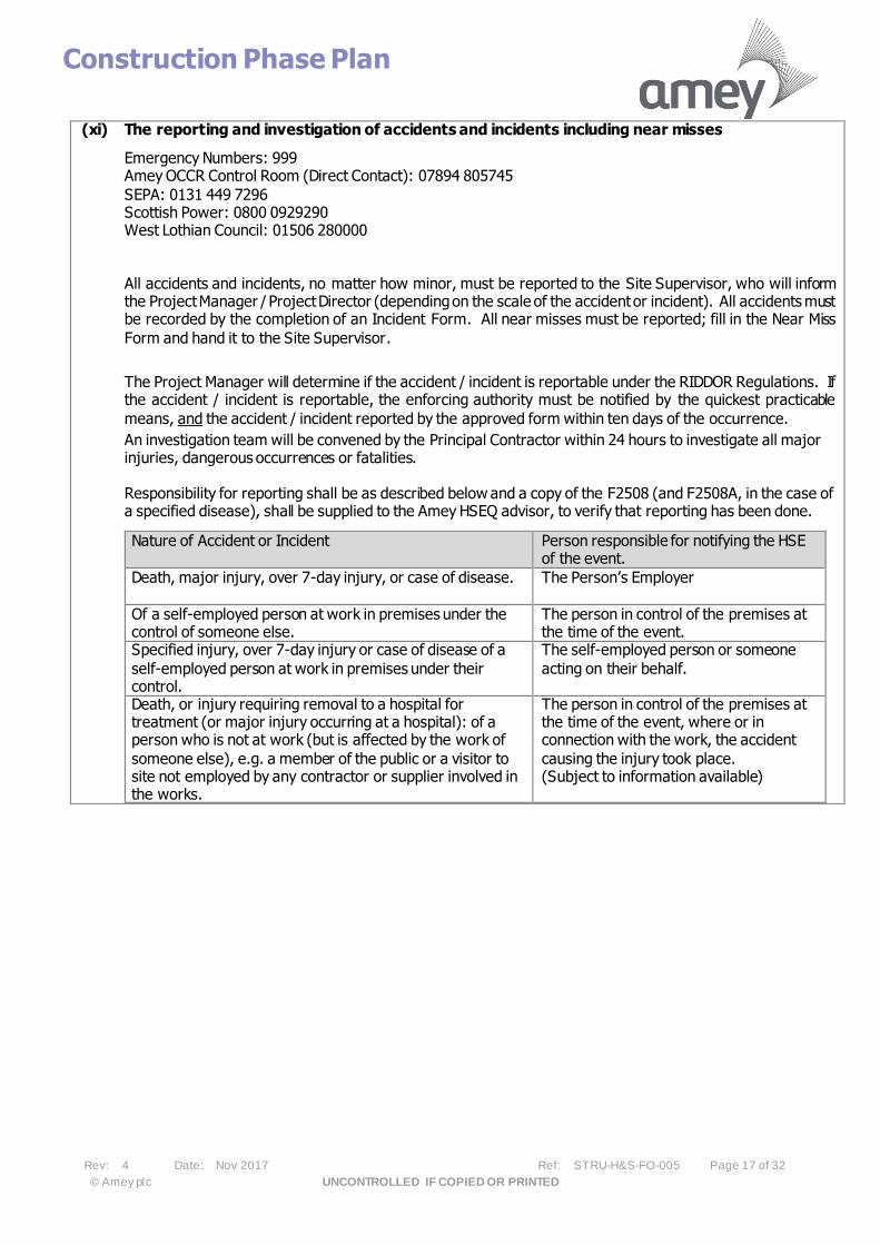
(xi) The reporting and investigation of accidents and incidents including near misses
Emergency Numbers: 999 Amey OCCR Control Room (Direct Contact): 07894 805745
SEPA: 0131 449 7296 Scottish Power: 0800 0929290 West Lothian Council: 01506 280000
All accidents and incidents, no matter how minor, must be reported to the Site Supervisor, who will inform the Project Manager / Project Director (depending on the scale of the accident or incident). All accidents must be recorded by the completion of an Incident Form. All near misses must be reported; fill in the Near Miss
Form and hand it to the Site Supervisor.
The Project Manager will determine if the accident / incident is reportable under the RIDDOR Regulations. If the accident / incident is reportable, the enforcing authority must be notified by the quickest practicable
means, and the accident / incident reported by the approved form within ten days of the occurrence.
An investigation team will be convened by the Principal Contractor within 24 hours to investigate all major injuries, dangerous occurrences or fatalities. Responsibility for reporting shall be as described below and a copy of the F2508 (and F2508A, in the case of a specified disease), shall be supplied to the Amey HSEQ advisor, to verify that reporting has been done.
Nature of Accident or Incident Person responsible for notifying the HSE of the event.
Death, major injury, over 7-day injury, or case of disease. The Person’s Employer
Of a self-employed person at work in premises under the control of someone else.
The person in control of the premises at the time of the event.
Specified injury, over 7-day injury or case of disease of a
self-employed person at work in premises under their control.
The self-employed person or someone
acting on their behalf.
Death, or injury requiring removal to a hospital for treatment (or major injury occurring at a hospital): of a person who is not at work (but is affected by the work of
someone else), e.g. a member of the public or a visitor to site not employed by any contractor or supplier involved in the works.
The person in control of the premises at the time of the event, where or in connection with the work, the accident
causing the injury took place. (Subject to information available)

Construction Phase Plan
Rev: 4 Date: Nov 2017 Ref: STRU-H&S-FO-005 Page 18 of 32
© Amey plc UNCONTROLLED IF COPIED OR PRINTED
(xii) The production and approval of risk assessments and written systems of work
The production and approval of risk assessments and written systems of work shall be as follows:
Contractor produces risk
assessment
│ │
Principal Contractor reviews
Accept │ │
Site Induction / Work Box
Talk by Contractor prior to
works commecning
│ │
Work on site
On this project the approval of Risk Assessments shall be the responsibility o
2.5 Site Rules
• Site visitors to report their presence & departure to site supervisor/manager or foreman. • Safety helmets and Boots must be worn at all times.
• Highways Reflective PPE to be worn at all times. • Storage areas must be agreed in writing prior to use. • No person to be on site under the influence of drugs, alcohol or any other stimulants. • No reversing of vehicles without a banks person.
Initial site rules will be reviewed by Principal Contractor
2.6 Fire and emergency procedures
• A designated fire assembly point shall be set up within the site confines. This is shown on the drawing in appendix A.
• Fire extinguishers are located in the welfare unit and works vehicles. Do not use fire extinguishers unless you are trained to do so.
• Site induction will include Fire Precautions e.g. correct storage of materials, waste collections etc. and the actions to take in the event of a fire.
• In the event of an accident, contact the appropriate emergency service.
• The location of the Hospital and details of the route is found in Appendix A of this document. • Any accident or incident involving employees, contractors or the public is to be reported immediately to the
Site Supervisor.
• The Incident Forms are held by the Site Supervisor; ensure that all accidents are entered (with a supervisor present to provide assistance).
Initial procedures will be reviewed by Principal Contractor
3.0 Arrangements for controlling significant site risks 3.1 Safety risks, including:
(i) Delivery and removal of materials and work equipment Delivery or waste collection vehicles will access the site from Eastbound Works Access (designate points of access / egress)
redacted 11(2)
Construction Phase Plan
Rev: 4 Date: Nov 2017 Ref: STRU-H&S-FO-005 Page 19 of 32
© Amey plc UNCONTROLLED IF COPIED OR PRINTED
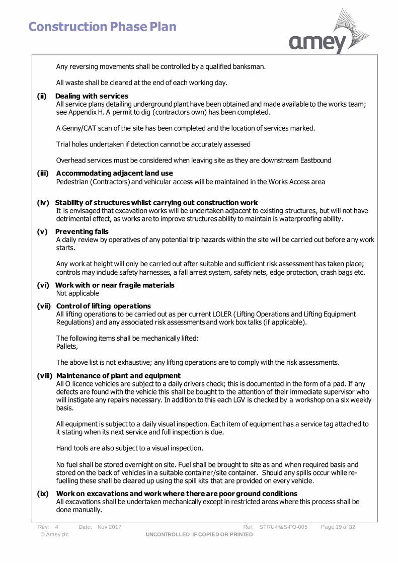
Any reversing movements shall be controlled by a qualified banksman. All waste shall be cleared at the end of each working day.
(ii) Dealing with services All service plans detailing underground plant have been obtained and made available to the works team; see Appendix H. A permit to dig (contractors own) has been completed. A Genny/CAT scan of the site has been completed and the location of services marked. Trial holes undertaken if detection cannot be accurately assessed Overhead services must be considered when leaving site as they are downstream Eastbound
(iii) Accommodating adjacent land use
Pedestrian (Contractors) and vehicular access will be maintained in the Works Access area
(iv) Stability of structures whilst carrying out construction work It is envisaged that excavation works will be undertaken adjacent to existing structures, but will not have detrimental effect, as works are to improve structures ability to maintain is waterproofing ability.
(v) Preventing falls A daily review by operatives of any potential trip hazards within the site will be carried out before any work starts. Any work at height will only be carried out after suitable and sufficient risk assessment has taken place;
controls may include safety harnesses, a fall arrest system, safety nets, edge protection, crash bags etc.
(vi) Work with or near fragile materials Not applicable
(vii) Control of lifting operations All lifting operations to be carried out as per current LOLER (Lifting Operations and Lifting Equipment Regulations) and any associated risk assessments and work box talks (if applicable). The following items shall be mechanically lifted: Pallets, The above list is not exhaustive; any lifting operations are to comply with the risk assessments.
(viii) Maintenance of plant and equipment All O licence vehicles are subject to a daily drivers check; this is documented in the form of a pad. If any defects are found with the vehicle this shall be bought to the attention of their immediate supervisor who will instigate any repairs necessary. In addition to this each LGV is checked by a workshop on a six weekly basis. All equipment is subject to a daily visual inspection. Each item of equipment has a service tag attached to it stating when its next service and full inspection is due. Hand tools are also subject to a visual inspection.
No fuel shall be stored overnight on site. Fuel shall be brought to site as and when required basis and stored on the back of vehicles in a suitable container/site container. Should any spills occur while re-fuelling these shall be cleared up using the spill kits that are provided on every vehicle.
(ix) Work on excavations and work where there are poor ground conditions All excavations shall be undertaken mechanically except in restricted areas where this process shall be done manually.

Construction Phase Plan
Rev: 4 Date: Nov 2017 Ref: STRU-H&S-FO-005 Page 20 of 32
© Amey plc UNCONTROLLED IF COPIED OR PRINTED
No access to open trenches is permitted unless a suitable trench support system is in place. All statutory undertakers plans have been made available to the works team, however where it is not clear when a particular service is located a hand dug trial hole shall be excavated. A CAT scan of the full site
shall be undertaken and the position of services shall be marked on the ground in paint.
(x) Traffic routes and segregation of vehicles and pedestrians The site shall be signed and guarded in accordance with Chapter 8 regulations. Please see appendix A for the temporary traffic management plan. The immediate works area shall be protected using Deltabloc TVRS (Phase 1) and Total Carriageway Closure (Phase 2/3). The position and spacing of the signs shall comply with Safety at Streetworks and Roadworks – a code of practice.
(xi) Storage of materials and work equipment No materials shall be stored on site overnight. The site shall be cleared at the end of each working day.
Small plant and hand tools are to be stored overnight in the container provided by Contractor.
(xii) Any other significant safety risks Please refer to Appendix D of this document.
Initial safety risks will be reviewed by Principal Contractor
3.2 Health Risks.
(i) The removal of asbestos None believed to be present, but if found on site work is to cease and the Principal Contractor is to be informed.
(ii) Dealing with contaminated land None believed to be present, but if found on site work is to cease and the Principal Contractor is to be informed.
(iii) Manual handling Please refer to Risk Assessments within Appendix F.
(iv) Use of hazardous substances, particularly where there is a need for health monitoring Normal construction materials are to be used on this project. COSHH assessments are carried out and stored within Appendix F.
(v) Reducing noise and vibration Low noise breaking equipment shall be used. The Principal Contractor will check this on site. Please see appendix F for risk assessment regarding hand breakers. The Contractor will ensure checks on HAV are recorded for inspection
(vii) Exposure to UV radiation Barrier cream shall be made available to all site staff for the duration of the works, should the weather improve
(viii) Any other significant health risks
Please refer to Appendix F of this document.
Initial health risks will be reviewed by Principal Contractor

Construction Phase Plan
Rev: 4 Date: Nov 2017 Ref: STRU-H&S-FO-005 Page 21 of 32
© Amey plc UNCONTROLLED IF COPIED OR PRINTED
4.0 Health and Safety File
4.1 Format
The Health and Safety File shall contain the information needed to allow future construction work including maintenance, alterations and demolition to be carried out safely. The level of detail should allow the likely risks to be identified and addressed by those carrying out the work:
4.2 Arrangements for collecting information
Information will be collated as the work progresses and held on site. When the work is completed the Principal Contractor will submit the information collected to the Principal Designer for inclusion in the Health and Safety File.
4.3 Storage of information
It is essential that clear concise records are kept. These may consist of annotated construction drawings, site notes, photographs, COSHH assessments and other relevant information.

Construction Phase Plan
Rev: 4 Date: Nov 2017 Ref: STRU-H&S-FO-005 Page 22 of 32
© Amey plc UNCONTROLLED IF COPIED OR PRINTED
Appendix A
Project Information
1) Location of A & E 2) Emergency Procedures
3) Fire Management Plan 4) Traffic Management Plan 5) Programme of Works

Construction Phase Plan
Rev: 4 Date: Nov 2017 Ref: STRU-H&S-FO-005 Page 23 of 32
© Amey plc UNCONTROLLED IF COPIED OR PRINTED
Appendix B
Additional Organograms / Competency Evidence

Construction Phase Plan
Rev: 4 Date: Nov 2017 Ref: STRU-H&S-FO-005 Page 24 of 32
© Amey plc UNCONTROLLED IF COPIED OR PRINTED
Appendix C
Amey Policies
Construction Phase Plan
Rev: 4 Date: Nov 2017 Ref: STRU-H&S-FO-005 Page 25 of 32
© Amey plc UNCONTROLLED IF COPIED OR PRINTED
Appendix D
Risk Assessments / Method Statements
Construction Phase Plan
Rev: 4 Date: Nov 2017 Ref: STRU-H&S-FO-005 Page 26 of 32
© Amey plc UNCONTROLLED IF COPIED OR PRINTED
Appendix E
Site Inductions

Construction Phase Plan
Rev: 4 Date: Nov 2017 Ref: STRU-H&S-FO-005 Page 27 of 32
© Amey plc UNCONTROLLED IF COPIED OR PRINTED
Appendix F
Hazardous Materials / COSHH Assessments

Construction Phase Plan
Rev: 4 Date: Nov 2017 Ref: STRU-H&S-FO-005 Page 28 of 32
© Amey plc UNCONTROLLED IF COPIED OR PRINTED
Appendix G
Product Data Sheets

Construction Phase Plan
Rev: 4 Date: Nov 2017 Ref: STRU-H&S-FO-005 Page 29 of 32
© Amey plc UNCONTROLLED IF COPIED OR PRINTED
Appendix H
Drawings and Information 1) Statutory Undertakers 2) Designers Drawings 3) PC’s Drawings 4) Contractor Drawings

Construction Phase Plan
Rev: 4 Date: Nov 2017 Ref: STRU-H&S-FO-005 Page 30 of 32
© Amey plc UNCONTROLLED IF COPIED OR PRINTED
Appendix I
Structural Principles and Test Certification

Construction Phase Plan
Rev: 4 Date: Nov 2017 Ref: STRU-H&S-FO-005 Page 31 of 32
© Amey plc UNCONTROLLED IF COPIED OR PRINTED
Appendix J
F10

Construction Phase Plan
Rev: 4 Date: Nov 2017 Ref: STRU-H&S-FO-005 Page 32 of 32
© Amey plc UNCONTROLLED IF COPIED OR PRINTED
Appendix K
Pre-Construction Information
Designer Hazard Aide Memoire
M8 Junction 4 Whitburn Bridges – Superstructure Works
Rev: 01 Date: February 2018
Ref: STRU-HS-FO-004 Page 1 of 15
© Amey plc UNCONTROLLED IF COPIED OR PRINTED
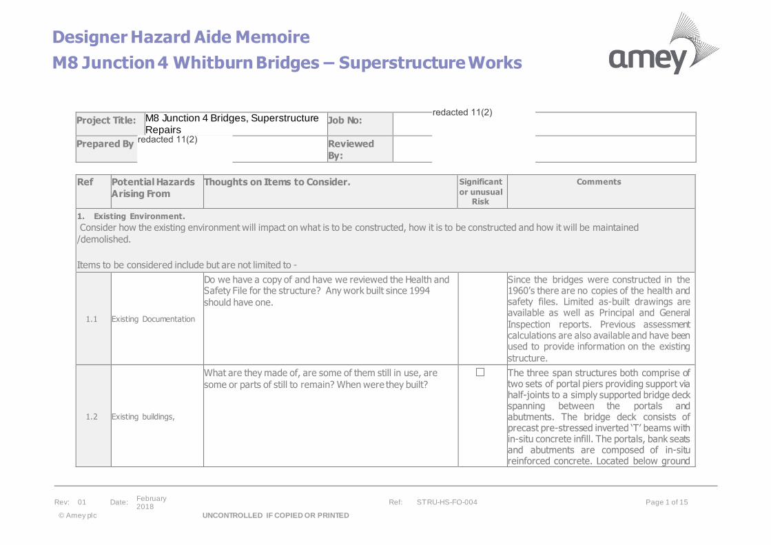
Project Title: M8 Junction 4 Bridges, Superstructure Repairs
Job No:
Prepared By Reviewed
By:
Ref Potential Hazards
Arising From
Thoughts on Items to Consider. Significant
or unusual Risk
Comments
1. Existing Environment.
Consider how the existing environment will impact on what is to be constructed, how it is to be constructed and how it will be maintained
/demolished.
Items to be considered include but are not limited to -
1.1 Existing Documentation
Do we have a copy of and have we reviewed the Health and Safety File for the structure? Any work built since 1994
should have one.
Since the bridges were constructed in the 1960’s there are no copies of the health and safety files. Limited as-built drawings are available as well as Principal and General
Inspection reports. Previous assessment calculations are also available and have been used to provide information on the existing
structure.
1.2 Existing buildings,
What are they made of, are some of them still in use, are
some or parts of still to remain? When were they built?
The three span structures both comprise of two sets of portal piers providing support via half-joints to a simply supported bridge deck spanning between the portals and abutments. The bridge deck consists of precast pre-stressed inverted ‘T’ beams with in-situ concrete infill. The portals, bank seats and abutments are composed of in-situ reinforced concrete. Located below ground
redacted 11(2)
redacted 11(2)
Designer Hazard Aide Memoire
M8 Junction 4 Whitburn Bridges – Superstructure Works
Rev: 01 Date: February 2018
Ref: STRU-HS-FO-004 Page 2 of 15
© Amey plc UNCONTROLLED IF COPIED OR PRINTED
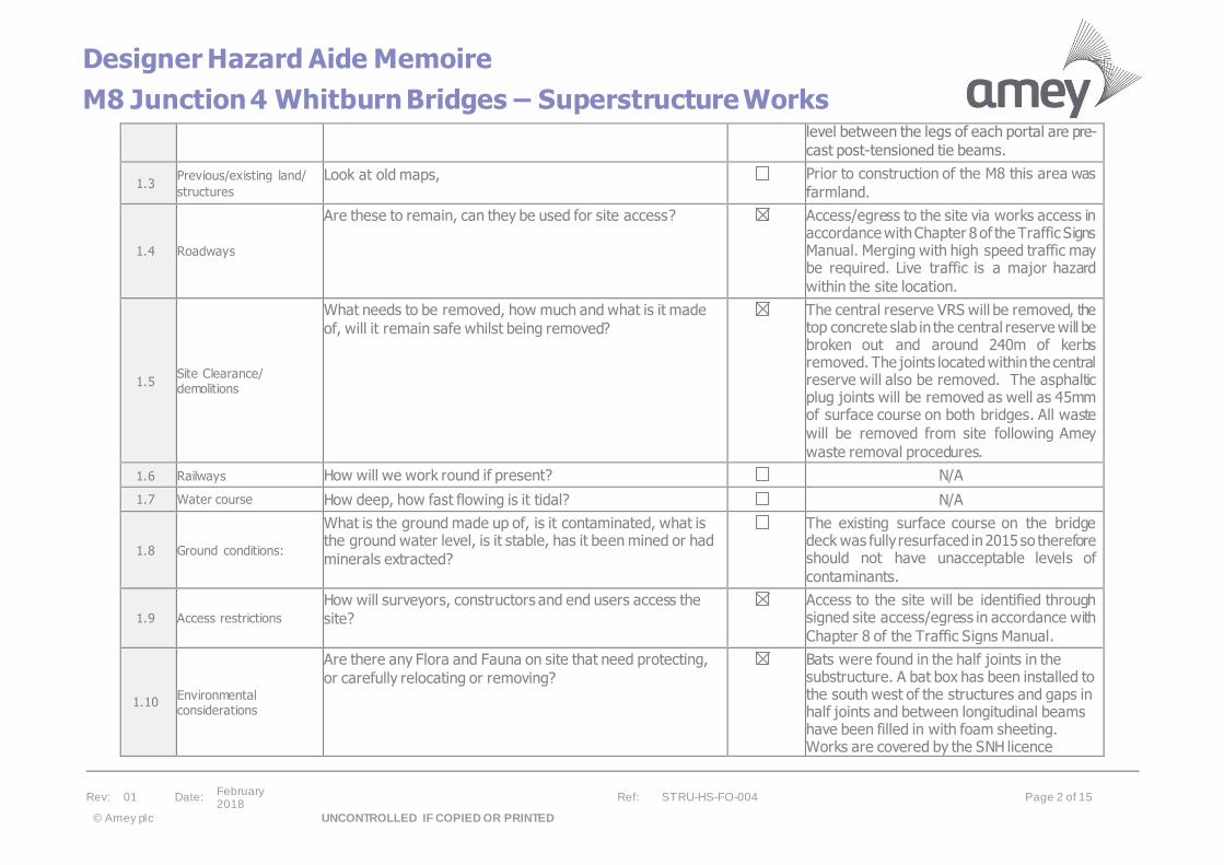
level between the legs of each portal are pre-
cast post-tensioned tie beams.
1.3 Previous/existing land/
structures
Look at old maps, Prior to construction of the M8 this area was
farmland.
1.4 Roadways
Are these to remain, can they be used for site access? Access/egress to the site via works access in accordance with Chapter 8 of the Traffic Signs Manual. Merging with high speed traffic may be required. Live traffic is a major hazard
within the site location.
1.5 Site Clearance/ demolitions
What needs to be removed, how much and what is it made
of, will it remain safe whilst being removed?
The central reserve VRS will be removed, the top concrete slab in the central reserve will be broken out and around 240m of kerbs removed. The joints located within the central reserve will also be removed. The asphaltic plug joints will be removed as well as 45mm of surface course on both bridges. All waste
will be removed from site following Amey
waste removal procedures.
1.6 Railways How will we work round if present? N/A
1.7 Water course How deep, how fast flowing is it tidal? N/A
1.8 Ground conditions:
What is the ground made up of, is it contaminated, what is the ground water level, is it stable, has it been mined or had
minerals extracted?
The existing surface course on the bridge deck was fully resurfaced in 2015 so therefore should not have unacceptable levels of
contaminants.
1.9 Access restrictions
How will surveyors, constructors and end users access the
site?
Access to the site will be identified through signed site access/egress in accordance with
Chapter 8 of the Traffic Signs Manual.
1.10 Environmental considerations
Are there any Flora and Fauna on site that need protecting,
or carefully relocating or removing?
Bats were found in the half joints in the substructure. A bat box has been installed to the south west of the structures and gaps in half joints and between longitudinal beams have been filled in with foam sheeting. Works are covered by the SNH licence

Designer Hazard Aide Memoire
M8 Junction 4 Whitburn Bridges – Superstructure Works
Rev: 01 Date: February 2018
Ref: STRU-HS-FO-004 Page 3 of 15
© Amey plc UNCONTROLLED IF COPIED OR PRINTED
ll operatives should be given bat briefing (Appendix E) before first shift on
this site and follow guidance given.
If bats are found all works must stop and a suitably licensed ecologist must be contacted. No attempt should be made to
handle any bats if found.
1.11 Adjacent properties/ inhabitants
What is next to the proposed site and how will the works
impact on it?
In the area, there are residential properties within 250m radius of the bridges and commercial building within 350m north of the bridges. The works may cause an increase in
noise and congestion to the surrounding area.
1.12 Concurrent site
activities What else is going on that could impact on the works? N/A
1.13 Interface with the public
How will the works be separated from the general public? The works will be completed on the motorway and should pose minimum risk to pedestrians. Traffic management will be in place throughout the works which may cause delays to road users. Temporary Barriers will be installed when the central reserve works are being completed as this will leave the thin bottom slab exposed. There is a footpath
under the west bridge but used infrequently.
1.14 Existing Utilities
What existing services cross or serve the site, can they be
removed? A 33kV underground Scottish Power line has
been identified to the east of Whitburn East Bridge. Site meeting with SPEN and further
site investigation indicate that the cable runs underneath the revetment of the structure. CAT & Genny scans should still be completed in the central reserve before excavation of slab and installation of new barrier posts. Hand digging should be adopted where
possible if cables are identified.
redacted 11(2)
Designer Hazard Aide Memoire
M8 Junction 4 Whitburn Bridges – Superstructure Works
Rev: 01 Date: February 2018
Ref: STRU-HS-FO-004 Page 4 of 15
© Amey plc UNCONTROLLED IF COPIED OR PRINTED
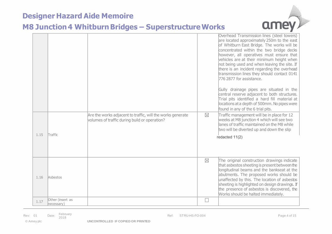
Overhead Transmission lines (steel towers) are located approximately 250m to the east of Whitburn East Bridge. The works will be
concentrated within the two bridge decks however, all operatives must ensure that vehicles are at their minimum height when not being used and when leaving the site. If there is an incident regarding the overhead transmission lines they should contact 0141
776 2877 for assistance.
Gully drainage pipes are situated in the central reserve adjacent to both structures. Trial pits identified a hard fill material at locations at a depth of 500mm. No pipes were
found in any of the 6 trial pits.
1.15 Traffic
Are the works adjacent to traffic, will the works generate
volumes of traffic during build or operation? Traffic management will be in place for 12
weeks at M8 junction 4 which will see two lanes of traffic maintained on the M8 while
two will be diverted up and down the slip
1.16 Asbestos
The original construction drawings indicate that asbestos sheeting is present between the longitudinal beams and the bankseat at the abutments. The proposed works should be
unaffected by this. The location of asbestos sheeting is highlighted on design drawings. If the presence of asbestos is discovered, the
Works should be halted immediately.
1.17 Other (insert as necessary)
redacted 11(2)
Designer Hazard Aide Memoire
M8 Junction 4 Whitburn Bridges – Superstructure Works
Rev: 01 Date: February 2018
Ref: STRU-HS-FO-004 Page 5 of 15
© Amey plc UNCONTROLLED IF COPIED OR PRINTED
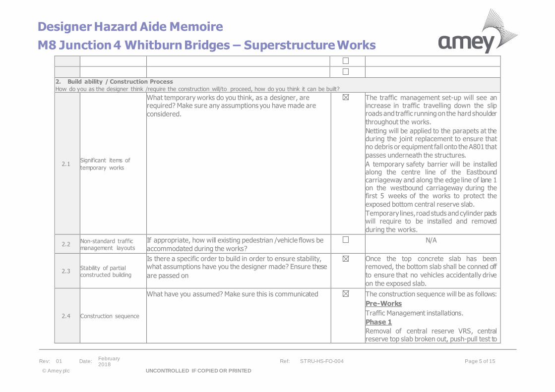
2. Build ability / Construction Process
How do you as the designer think /require the construction will/to proceed, how do you think it can be built?
2.1 Significant items of
temporary works
What temporary works do you think, as a designer, are required? Make sure any assumptions you have made are
considered.
The traffic management set-up will see an increase in traffic travelling down the slip roads and traffic running on the hard shoulder
throughout the works.
Netting will be applied to the parapets at the during the joint replacement to ensure that no debris or equipment fall onto the A801 that
passes underneath the structures.
A temporary safety barrier will be installed along the centre line of the Eastbound carriageway and along the edge line of lane 1 on the westbound carriageway during the first 5 weeks of the works to protect the
exposed bottom central reserve slab.
Temporary lines, road studs and cylinder pads will require to be installed and removed
during the works.
2.2 Non-standard traffic management layouts
If appropriate, how will existing pedestrian /vehicle flows be
accommodated during the works?
N/A
2.3 Stability of partial constructed building
Is there a specific order to build in order to ensure stability, what assumptions have you the designer made? Ensure these
are passed on
Once the top concrete slab has been removed, the bottom slab shall be conned off
to ensure that no vehicles accidentally drive
on the exposed slab.
2.4 Construction sequence
What have you assumed? Make sure this is communicated The construction sequence will be as follows:
Pre-Works
Traffic Management installations.
Phase 1
Removal of central reserve VRS, central reserve top slab broken out, push-pull test to
Designer Hazard Aide Memoire
M8 Junction 4 Whitburn Bridges – Superstructure Works
Rev: 01 Date: February 2018
Ref: STRU-HS-FO-004 Page 6 of 15
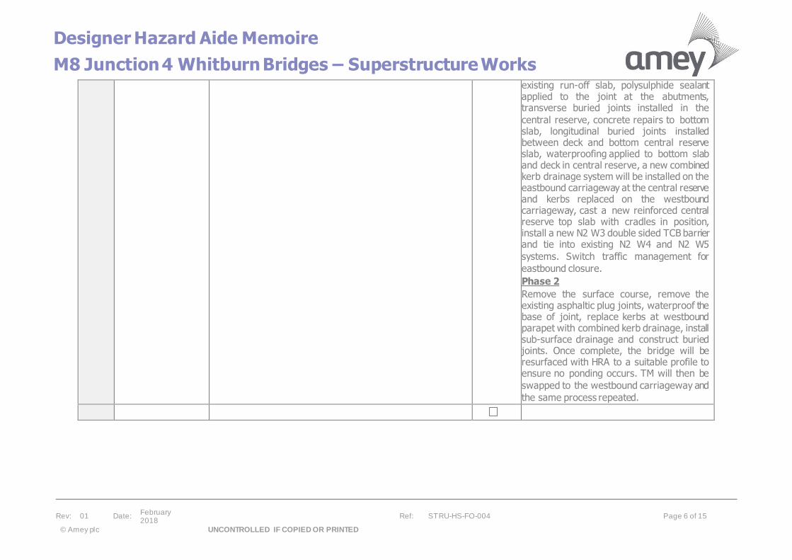
© Amey plc UNCONTROLLED IF COPIED OR PRINTED
existing run-off slab, polysulphide sealant applied to the joint at the abutments, transverse buried joints installed in the
central reserve, concrete repairs to bottom slab, longitudinal buried joints installed between deck and bottom central reserve slab, waterproofing applied to bottom slab and deck in central reserve, a new combined kerb drainage system will be installed on the eastbound carriageway at the central reserve and kerbs replaced on the westbound carriageway, cast a new reinforced central reserve top slab with cradles in position, install a new N2 W3 double sided TCB barrier and tie into existing N2 W4 and N2 W5
systems. Switch traffic management for
eastbound closure.
Phase 2
Remove the surface course, remove the existing asphaltic plug joints, waterproof the base of joint, replace kerbs at westbound parapet with combined kerb drainage, install sub-surface drainage and construct buried joints. Once complete, the bridge will be resurfaced with HRA to a suitable profile to ensure no ponding occurs. TM will then be
swapped to the westbound carriageway and
the same process repeated.
Designer Hazard Aide Memoire
M8 Junction 4 Whitburn Bridges – Superstructure Works
Rev: 01 Date: February 2018
Ref: STRU-HS-FO-004 Page 7 of 15
© Amey plc UNCONTROLLED IF COPIED OR PRINTED
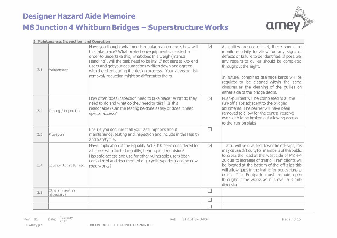
3. Maintenance, Inspection and Operation
3.1 Maintenance
Have you thought what needs regular maintenance, how will this take place? What protection/equipment is needed in order to undertake this, what does this weigh (manual Handling), will the task need to be lit? If not sure talk to end users and get your assumptions written down and agreed with the client during the design process. Your views on risk
removal/ reduction might be different to theirs.
As gullies are not off-set, these should be monitored daily to allow for any signs of defects or failure to be identified. If possible, any repairs to gullies should be completed
throughout the night.
In future, combined drainage kerbs will be required to be cleaned within the same
closures as the cleaning of the gullies on
either side of the bridge decks.
3.2 Testing / inspection
How often does inspection need to take place? What do they need to do and what do they need to test? Is this
reasonable? Can the testing be done safely or does it need
special access?
Push-pull test will be completed to all the run-off slabs adjacent to the bridges
abutments. The barrier will have been removed to allow for the central reserve over-slab to be broken out allowing access
to the run-on slabs.
3.3 Procedure
Ensure you document all your assumptions about maintenance, testing and inspection and include in the Health
and Safety file.
3.4 Equality Act 2010 etc.
Have implication of the Equality Act 2010 been considered for
all users with limited mobility, hearing and /or vision?
Has safe access and use for other vulnerable users been considered and documented e.g. cyclists/pedestrians on new
road works?
Traffic will be diverted down the off-slips, this may cause difficulty for members of the public
to cross the road at the west side of M8 4-4 20 due to increase of traffic. Traffic lights will be located at the bottom of the off slips this will allow gaps in the traffic for pedestrians to cross. The Footpath must remain open throughout the works as it is over a 3 mile
diversion.
3.5 Others (insert as necessary)

Designer Hazard Aide Memoire
M8 Junction 4 Whitburn Bridges – Superstructure Works
Rev: 01 Date: February 2018
Ref: STRU-HS-FO-004 Page 8 of 15
© Amey plc UNCONTROLLED IF COPIED OR PRINTED
4. Earthworks
4.1
What do I as the
designer need to inform the contractor about
that is not clear from
the drawings to a competent contractor
Is the excavation depth clear? Are there any slope stability
issues? What is the ground water level, will it fluctuate?
Are any water courses affected? How do we anticipate the contractor’s plant will move around, document this assumption? Are any services clearly shown? Is there any ground contamination? Have we made any construction
sequence assumptions that affect other parts of the work?
Excavation will be completed to tie in combined kerb drainage to existing gullies in 5 locations. Excavation at the east of Whitburn East must be CAT & Jenny scanned prior to commencing digging. If the 33kV Scottish Power cable from the PU’s is
located in this area, this should be dug by
hand.
4.2 Grouting Consider, noise, contamination of ground, any grout loss and
where it goes. Unmarked drains being blocked? N/A
4.3 Others (insert as
necessary)
5. Foundations
5.1
What do I as the
designer need to inform
the contractor about that is not clear from
the drawings to a competent contractor
Are foundation depths clear? How do we think the contractor will build the foundations, what plant will he use and how will it move around? Have we documented this assumption, have we checked it with a competent contractor? How do the foundations impact on existing and proposed services? How will this impact on the phasing of the works? Are there any
contamination, ground water or water courses to deal with?
Will we create or have to deal with any confined spaces?
N/A
5.2 Piling:
Have we considered in addition to the above:
• Noise
• Vibration
• How the contractor will install in terms of plant and
access.
And their impact on the proposed works, the existing
environment and neighbours?
N/A
5.3 Stability of structure
Does foundation work impact on existing structures? does construction sequence require foundations to be built in any
order?
N/A

Designer Hazard Aide Memoire
M8 Junction 4 Whitburn Bridges – Superstructure Works
Rev: 01 Date: February 2018
Ref: STRU-HS-FO-004 Page 9 of 15
© Amey plc UNCONTROLLED IF COPIED OR PRINTED
5.4 Others (insert as necessary)
6. Drainage /below ground service installation Works
6.1
What do I as the designer need to inform
the contractor about
that is not clear from the drawings to a
competent contractor
Is excavation depth and stability clear from the information I have supplied? Have ground water conditions, confined
spaces, contaminated land issues been communicated?
What existing and proposed services are affected by the drainage works? Is there a sequence of works the contractor needs to be aware of? How will the contractor construct the
drainage? can he get his equipment to do this in, how heavy
are the materials?
A combined kerb drainage system will be installed on the eastbound carriageway of both bridge decks adjacent to the central reserve and on the westbound carriageway of both bridge decks adjacent to the parapets. Subsurface drainage will also be installed at all joints and tied into the combined kerb drainage. The combined kerbs will be tied into the existing drainage system. Locations of combined kerb drainage, subsurface drainage and tying in will be clearly identified on
drawings.
6.2 Others (insert as
necessary)
7. Highways
7.1
What do I as the
designer need to inform
the contractor about that is not clear from
the drawings to a competent contractor
How will the works be constructed?
What traffic management is required?
How will non-motorised users deal with the works?
What plant is required to undertake the work, how will this
access the site?
Will the works impact on adjacent structures?
When will the works be carried out? Day or Night?
Are they noisy, will they cause vibration?
What has been assumed? Have we told the contractor this?
Phase 1:
Traffic Management will see the closure of lane 1 and 2 in the eastbound carriageway and a closure of lane 2 in the westbound
carriageway. A temporary safety barrier will be installed adjacent to the lane 1 edge line eastbound and along the centre line westbound. This is to protect the bottom
central reserve slab once exposed.
Eastbound traffic will be diverted onto the
hard shoulder and down and up the slip roads. Westbound traffic will be diverted down and up the slip road and onto lane 1. The Traffic Management will be in operation
Designer Hazard Aide Memoire
M8 Junction 4 Whitburn Bridges – Superstructure Works
Rev: 01 Date: February 2018
Ref: STRU-HS-FO-004 Page 10 of 15
© Amey plc UNCONTROLLED IF COPIED OR PRINTED
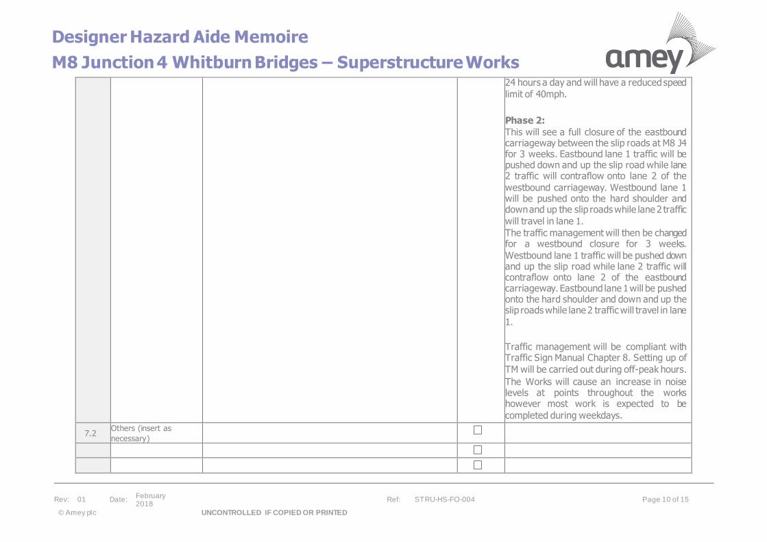
24 hours a day and will have a reduced speed
limit of 40mph.
Phase 2:
This will see a full closure of the eastbound carriageway between the slip roads at M8 J4 for 3 weeks. Eastbound lane 1 traffic will be pushed down and up the slip road while lane 2 traffic will contraflow onto lane 2 of the
westbound carriageway. Westbound lane 1 will be pushed onto the hard shoulder and down and up the slip roads while lane 2 traffic
will travel in lane 1.
The traffic management will then be changed for a westbound closure for 3 weeks.
Westbound lane 1 traffic will be pushed down and up the slip road while lane 2 traffic will contraflow onto lane 2 of the eastbound carriageway. Eastbound lane 1 will be pushed onto the hard shoulder and down and up the slip roads while lane 2 traffic will travel in lane
1.
Traffic management will be compliant with Traffic Sign Manual Chapter 8. Setting up of
TM will be carried out during off-peak hours.
The Works will cause an increase in noise levels at points throughout the works however most work is expected to be
completed during weekdays.
7.2 Others (insert as
necessary)

Designer Hazard Aide Memoire
M8 Junction 4 Whitburn Bridges – Superstructure Works
Rev: 01 Date: February 2018
Ref: STRU-HS-FO-004 Page 11 of 15
© Amey plc UNCONTROLLED IF COPIED OR PRINTED
8. Steelwork Construction
8.1
What do I as the
designer need to inform
the contractor about that is not clear from
the drawings to a competent contractor
How have we assumed the contractor will build the structure?
Have we minimised the need to work at height?
How will the contractor undertake any lifting operations, is
the ground safe for the crane loads?
What have we assumed about temporary stability?
Are there any unusual constructions sequences required or
anticipated?
How will the steelwork be maintained/inspected?
Reinforcement will be transported to site and lowered from lorry to ground level by a crawler crane. As individual bars these will
then be lifted into place by operatives.
A new steel N2 W3 barrier will be installed for approximately 175m. Push pull tests will be completed on driven and anchored posts
to ensure they are of a suitable standard.
8.2 Others (insert as
necessary)
9. Concrete Construction
9.1
What do I as the
designer need to inform the contractor about
that is not clear from the drawings to a
competent contractor
How will the contractor pour and form the concrete?
Document any assumptions
What plant does he need, how will he get it to site?
Is the ground suitable for any lifting operations or heavy
deliveries?
What construction sequence have we assumed?
Is there any temporary instability, propping requirement are
these detailed on the drawings?
Any post/pre tensioning issues
Any joints, Scabbling back should not be specified.
DSR will then identify areas where concrete repairs will be completed to deck at joints.
This will also be measured by DSR.
The concrete top slab in both central reserves will be broken out to the depth as marked on drawing under the supervision of a DSR. DSR will then identify areas where concrete repairs will be completed prior to
the waterproofing of slab.
No loading should be applied to the bottom
slab once the top slab has been removed.
A new reinforced concrete top slab will then be cast on top along with anchors for the
new VRS barrier.
9.2 Others (insert as necessary)
Depth of central reserve slab to be removed to be clearly shown on design drawings. DSR
to be present on site during this operation.

Designer Hazard Aide Memoire
M8 Junction 4 Whitburn Bridges – Superstructure Works
Rev: 01 Date: February 2018
Ref: STRU-HS-FO-004 Page 12 of 15
© Amey plc UNCONTROLLED IF COPIED OR PRINTED
10. Masonry Construction
10.1
What do I as the
designer need to inform the contractor about
that is not clear from the drawings to a
competent contractor
Have unit weights been shown if more than 25kg?
How will the contractor deliver to the work face, are the
ground conditions /structural stability suitable?
Are there unusual limits to the speed of construction to
ensure stability is maintained?
How has the need to work at height been addressed?
How is durability addressed?
Have we considered catastrophic collapse?
N/A
10.2 Others (insert as necessary)
11. Other Forms of Construction e.g. Timber. Glass
11.1
What do I as the
designer need to inform the contractor about
that is not clear from
the drawings to a competent contractor
Have unit weights been shown if more than 25kg?
How will the contractor deliver to the work face, are the
ground conditions /structural stability suitable?
How has the need to work at height been addressed?
How is durability addressed?
What construction sequence have we assumed?
Is there any temporary instability, propping requirement are
these detailed on the drawings?
Have we considered catastrophic collapse?
N/A
11.2 Others (insert as necessary)
12. Mechanical/Electrical Systems
12.1
What do I as the
designer need to inform the contractor about
that is not clear from
How have we assumed the contractor will undertake the works? Is clear access available? Has the need to work at
VMS signs at J3 & J3A on the westbound carriageway verge and prior to J4a on the
Designer Hazard Aide Memoire
M8 Junction 4 Whitburn Bridges – Superstructure Works
Rev: 01 Date: February 2018
Ref: STRU-HS-FO-004 Page 13 of 15
© Amey plc UNCONTROLLED IF COPIED OR PRINTED
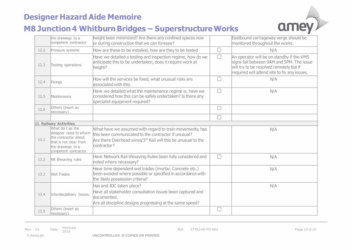
the drawings to a competent contractor
height been minimised? Are there any confined spaces now
or during construction that we can foresee?
Eastbound carriageway verge should be
monitored throughout the works.
12.2 Pressure systems How are these to be installed, how are they to be tested N/A
12.3 Testing operations
Have we detailed a testing and inspection regime, how do we anticipate this to be undertaken, does it require work at
height?
An operator will be on standby if the VMS signs fail between 9AM and 5PM. The issue will try to be resolved remotely but if
required will attend site to fix any issues.
12.4 Fixings How will the services be fixed, what unusual risks are
associated with this.
N/A
12.5 Maintenance
Have we detailed what the maintenance regime is, have we considered how this can be safely undertaken? Is there any
specialist equipment required?
N/A
12.6 Others (insert as necessary)
13. Railway Activities
13.1
What do I as the
designer need to inform the contractor about
that is not clear from
the drawings to a competent contractor
What have we assumed with regard to train movements, has
this been communicated to the contractor if unusual?
Are there Overhead wires/3rd Rail will this be unusual to the
contractor?
N/A
13.2 NR lifesaving rules Have Network Rail lifesaving Rules been fully considered and
noted where necessary? N/A
13.3 Wet Trades
Have time dependent wet trades (mortar, Concrete etc.) been avoided where possible or specified in accordance with
the likely possession criteria?
N/A
13.4 Interdisciplinary Issues.
Has and IDC taken place?
Have all stakeholder consultation issues been captured and
documented.
Are all discipline designs progressing at the same speed?
N/A
13.5 Others (insert as
necessary)
Designer Hazard Aide Memoire
M8 Junction 4 Whitburn Bridges – Superstructure Works
Rev: 01 Date: February 2018
Ref: STRU-HS-FO-004 Page 14 of 15
© Amey plc UNCONTROLLED IF COPIED OR PRINTED
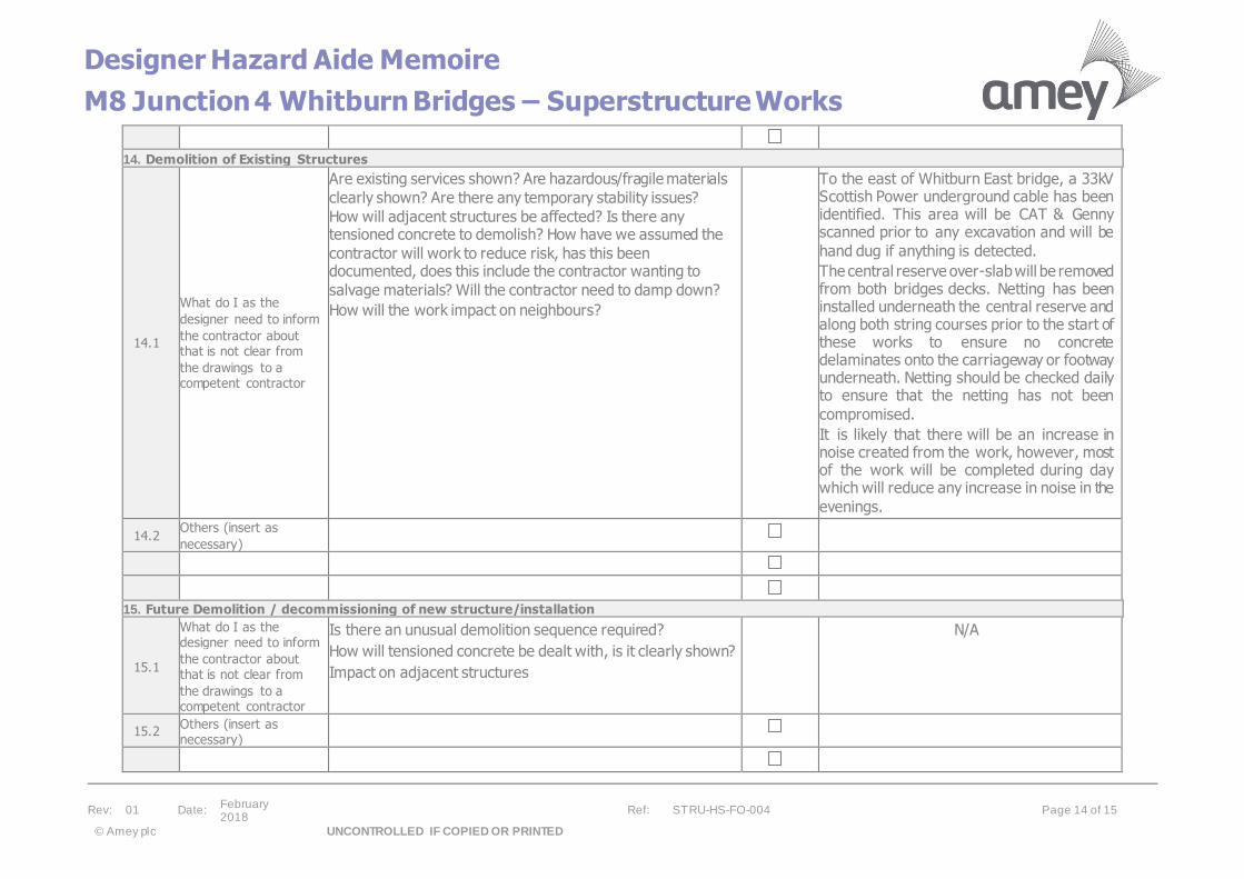
14. Demolition of Existing Structures
14.1
What do I as the
designer need to inform
the contractor about that is not clear from
the drawings to a competent contractor
Are existing services shown? Are hazardous/fragile materials
clearly shown? Are there any temporary stability issues?
How will adjacent structures be affected? Is there any tensioned concrete to demolish? How have we assumed the
contractor will work to reduce risk, has this been documented, does this include the contractor wanting to
salvage materials? Will the contractor need to damp down?
How will the work impact on neighbours?
To the east of Whitburn East bridge, a 33kV Scottish Power underground cable has been identified. This area will be CAT & Genny scanned prior to any excavation and will be
hand dug if anything is detected.
The central reserve over-slab will be removed from both bridges decks. Netting has been installed underneath the central reserve and along both string courses prior to the start of these works to ensure no concrete delaminates onto the carriageway or footway underneath. Netting should be checked daily to ensure that the netting has not been
compromised.
It is likely that there will be an increase in noise created from the work, however, most of the work will be completed during day which will reduce any increase in noise in the
evenings.
14.2 Others (insert as
necessary)
15. Future Demolition / decommissioning of new structure/installation
15.1
What do I as the designer need to inform
the contractor about that is not clear from
the drawings to a competent contractor
Is there an unusual demolition sequence required?
How will tensioned concrete be dealt with, is it clearly shown?
Impact on adjacent structures
N/A
15.2 Others (insert as necessary)
Designer Hazard Aide Memoire
M8 Junction 4 Whitburn Bridges – Superstructure Works
Rev: 01 Date: February 2018
Ref: STRU-HS-FO-004 Page 15 of 15
© Amey plc UNCONTROLLED IF COPIED OR PRINTED
Notes:
1. This is a living document and should be reviewed regularly as a project progresses
2. This list of potential hazards is not exhaustive and is designed to make you the designer think about what you are designing, how it can be
built, managed and demolished.
3. All significant and unusual risks considered by the designer must be addressed on the Hazard Management Schedule. This must also include risks that have been removed so that further stages of the project are able to understand what action was taken to remove the risk and not
inadvertently reinstate it.
4. The list and thoughts above are not exhaustive, if when using the form you find that specific items are frequently being added please advise
the standard owner so they can be considered for inclusion at the next revision.
5. Some of the questions are repeated in different sections , please make sure the output is kept as brief as possible to avoid a document so thick it won’t be read, if you consider a question has been adequately responded to earlier just make a note. An example would be ground
conditions for earthworks, drainage and foundations.
6. If you make an assumption about how the contractor will/needs to deal with any element of the work make sure you document it.
7. The check box for Significant or unusual risks is before design control measures are introduced.
Diack & Macaulay Ltd
Construction Services
7 Gartferry Road
Modiesburn
G690LY
01236875166
Stirling Lloyd Eliminator Installation (GCP)
Method statement 002
Site:
AMEY M8 Junction 4 superstructure works
1 THE PROJECT The Stirling Lloyd one coat Eliminator water-proofing system is
to be applied to the decking. The substrate is to be prepared by Diack and
Macaulay Ltd.
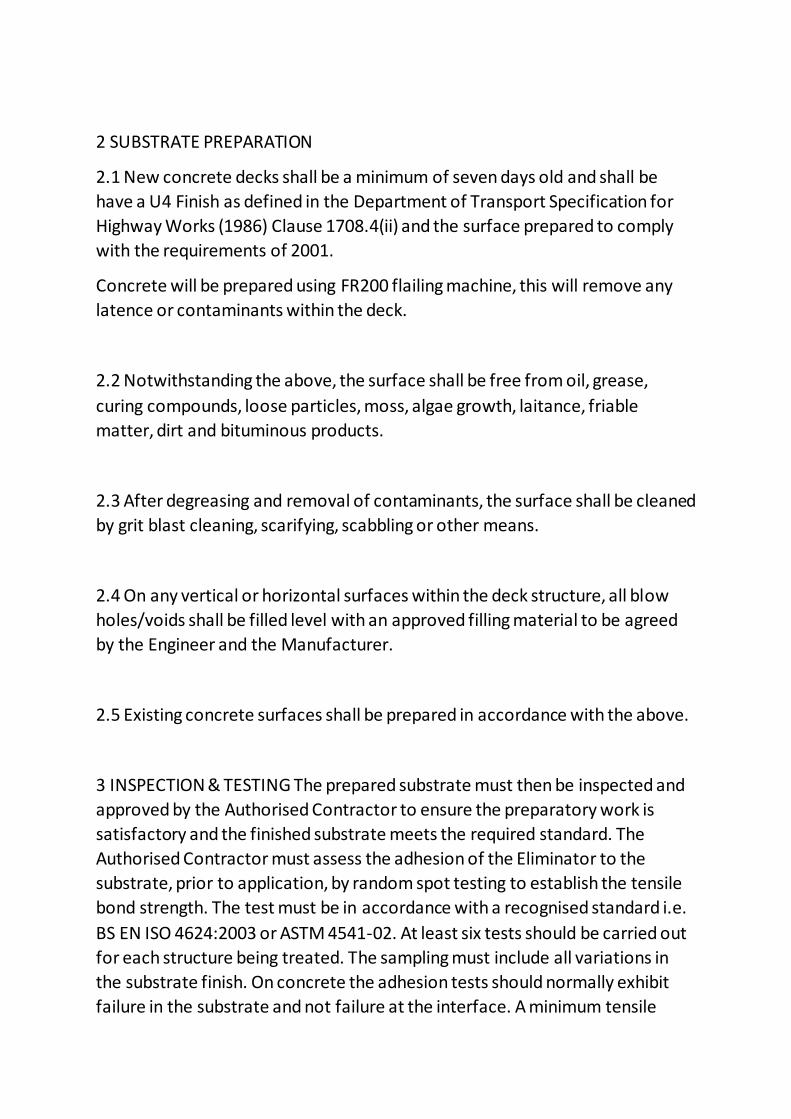
2 SUBSTRATE PREPARATION
2.1 New concrete decks shall be a minimum of seven days old and shall be
have a U4 Finish as defined in the Department of Transport Specification for
Highway Works (1986) Clause 1708.4(ii) and the surface prepared to comply
with the requirements of 2001.
Concrete will be prepared using FR200 flailing machine, this will remove any
latence or contaminants within the deck.
2.2 Notwithstanding the above, the surface shall be free from oil, grease,
curing compounds, loose particles, moss, algae growth, laitance, friable
matter, dirt and bituminous products.
2.3 After degreasing and removal of contaminants, the surface shall be cleaned
by grit blast cleaning, scarifying, scabbling or other means.
2.4 On any vertical or horizontal surfaces within the deck structure, all blow
holes/voids shall be filled level with an approved filling material to be agreed
by the Engineer and the Manufacturer.
2.5 Existing concrete surfaces shall be prepared in accordance with the above.
3 INSPECTION & TESTING The prepared substrate must then be inspected and
approved by the Authorised Contractor to ensure the preparatory work is
satisfactory and the finished substrate meets the required standard. The
Authorised Contractor must assess the adhesion of the Eliminator to the
substrate, prior to application, by random spot testing to establish the tensile
bond strength. The test must be in accordance with a recognised standard i.e.
BS EN ISO 4624:2003 or ASTM 4541-02. At least six tests should be carried out
for each structure being treated. The sampling must include all variations in
the substrate finish. On concrete the adhesion tests should normally exhibit
failure in the substrate and not failure at the interface. A minimum tensile

adhesion value of 0.7MPa must be achieved on concrete. All results should be
recorded on the Site Q.A & Materials Record. The mode of failure should also
be recorded. If any value falls below these requirements please contact our
Customer Services Department. Once the substrate has been cleaned
trafficking must be prevented.
3.1 APPLICATION OF PAR1 PRIMER
3.3 Immediately before use, stir the primer resin thoroughly using a
mechanical mixer, such as an air driven drill (400-800rpm) and mixing paddle.
Care should be taken not to entrain excessive air in the mix. Whilst continuing
stirring until it is added and completely dispersed. Note: If the PAR1 Primer is
supplied in a 200kg drum and is to be decanted into smaller containers it
should be stirred thoroughly immediately before it is decanted.
3.4 Once the BPO is added it initiates the ‘working life’ of the material during
which time it should be applied. The ‘working life’ of the material will vary
depending upon the quantity mixed, the ambient and material temperature
and the level of BPO addition. Refer to Appendix 4 for further information on
working life and cure times.
3.5 PAR1 Primer should be applied evenly to the substrate with a brush, roller
or airless spray. For spray application suitable equipment is Graco 23:1 Monark
airless spray pump (or similar) with a ¼” spray line and a spray tip size between
0.025” (25 thou) and 0.035” (35 thou).
3.6 The substrate should be completely wetted ensuring maximum penetration
so as to prevent pin holing and ensure good adhesion, however ‘ponding’ must
be avoided. Do not apply the PAR1 Primer once it starts to gel.
3.7 One application of PAR1 Primer is normally sufficient. When dry,
adequately sealed areas will display a glass like sheen finish. If it doesn’t then a
second coat must be applied.

3.8 The coverage rate will depend upon the porosity of the substrate but
should no less than 0.25kg/m².
3.9 Once the primer has been applied vehicular trafficking should be avoided
to prevent unnecessary contamination. The primer should be dry to the touch
and fully cured before the nest application stages starts.
4 APPLICATION OF ELIMINATOR MEMBRANE
4.1 The application shall follow the Stirling Lloyd Quality Assurance Statement
and the BBA Certification for the two coat Eliminator system
4.2 The Eliminator System shall be applied by a plural component airless spray
machine proportioning the Part A and the Part B material in the ratio of 1:1.
4.3 Part B component shall have a factory delivered pre-weighted sachet of
Benzole Peroxide mixed into it on site prior to blending with Component A.
4.4 The System shall be applied in two colour contrasting coats at 1.2mm wet
thickness each giving a total minimum dry thickness of 2mm.on peaks of ridged
concrete.
4.5 Before application of the colour contrasting second coat the first coat shall
be inspected and any defects repaired
4.6 During application of each coat, the thickness of the liquid membrane shall
be checked regularly using a wet film gauge. Any areas which may fall below
the approved thickness shall be over coated immediately.
4.7 Following the initial curing of the Eliminator Coating the total area shall be
visually inspected and repaired if necessary prior to application of the Tack
Coat.
4.8 Repairs will be carried out with Eliminator using Spray Equipment or Paint
Brush.
4.9 Bond Coat 3 shall be applied by airless spray system at a rate of 0.6kg/m
Bond Coat shall not be applied to areas of waterproofing membrane to be
overlapped. Such areas shall be masked by boards or tape and kept free from
Tack Coat. Bond Coat shall only be applied where surfacing is required directly
onto the waterproofing membrane.
5 PATCHING If an area is left untreated or the membrane becomes damaged, a
patch repair can easily be carried out to restore the integrity of the
waterproofing. The damaged area should be cut back to sound material and
wiped, with a rag soaked in Acetone upto a width of at least 100mm on the
periphery. The substrate should be primed if necessary and Eliminator material
applied, ensuring that a continuous membrane is obtained over the substrate
with a 100mm overlap onto the existing membrane.
6 LAPPING Where the Eliminator is to be jointed to existing cured Eliminator
Membrane and at day joints the new application shall be lapped into the
existing by at least 100mm. No preparation is necessary unless the existing
Eliminator margin is dirty or contaminated in which case the lapping margin
shall be first swabbed with Acetone. The overlap are interface must be kept
free of Tack Coat.
7 HEALTH AND SAFETY Data sheets for the Eliminator System to be used shall
be made available when required. It is the Company’s policy to take all
reasonable steps to prevent injury to all property and personnel from
foreseeable hazards. This extends to the public in so far as they come into
contact with the Company or its products
8 CONTROL MEASURES During windy conditions tip extensions shall be used.
And Morrisons will supply our staff with Heras fencing panels with sheeting
attached, this will prevent any over spray from interfering with live traffic or
site staff. All of the above will be used at all times to eliminate risk from gusts
or sudden change of conditions.
Attachments
Risk Assessments Reference Amey M8 Jct Superstructure
COSHH assessments 001, 002, 004, 010 and 031
Created by
Approved b
redacted 11(2)

Rev: 5 Date: June 2019 Ref: STRU-Operations – RAMS –023
Page 1 of 6
UNCONTROLLED IF COPIED OR PRINTED
Installation, Repairs and Maintenance of VRS
(Vehicle Restraint Systems)
1.0 Scope of Works
• This document details the methods and controls that are to be applied to the installation, repairs and maintenance of VRWS (Vehicle Restraint Systems)
2.0 Definitions
• N/a
3.0 Location
The location of the work is on the highways network and associated areas of all the Scottish Highways Contracts.
4.0 Safety Issues
.1 Resources
• Suitable Team Leader, and/or Operatives (Registered and Trained as per NHSS 2B Document).
.2 Work Equipment ▪ Barrier Rig (with or without Post Knocker, Lorry Loader and
Compressor), ▪ Petrol Disc Cutter, ▪ Pneumatic Wrench(es), ▪ Calibrated Torque Wrench(s), ▪ Various Hand Tools (digging tools, wrenches, etc.)
.3 Materials ▪ Various VRS Components ▪ Concrete (ready mixed or mixed on site)
.4 Traffic or Pedestrian Management • Suitable traffic management must be planned or in place for all Works
.5 Work Restrictions ▪ None
.6 Personal protective Equipment
• Hard Hat BS EN 397 • Eye Protection BS EN 116
• High Visibility Long Sleeve Jacket or Vest Class 3 BS EN 471
• High Visibility Yellow Trousers Class 3 BS EN471
• Steel Capped Safety Boots BS EN 20347 • Kevlar Gloves BS EN 388
• Ear protection BS EN 352:2:2003 SNR 37
Rev: 5 Date: June 2019 Ref: STRU-Operations – RAMS –023
Page 2 of 6
UNCONTROLLED IF COPIED OR PRINTED
5.0 Method of Carrying out the works
. Planning of Works • Traffic Management for VRS Works should be planned to ensure adequate
access for the required Barrier Rig, Excavation Equipment and Ready Mixed Concrete deliveries, etc.
• Repairs to central reserve damage will require twin offside lane closures, unless the central reserve is wide enough to safely carry out the works.
Storage of VRS Components
• Upon delivery, samples of the materials should be checked for conformance to the specification,
• All materials should be handled, transported and stored in such a way that damage to components and protective coatings is avoided,
• Beams and barriers should be stored in a safe manner, clear of the ground and in such a way that contact with groundwater, soil, ash or other deleterious materials is prevented and rainwater does not accumulate on the surfaces or inside hollow sections.
• Different grades and sizes of fasteners should be stored in separately labelled containers, under cover.
Loading of VRS Components • Loading of VRS Components should be carried out mechanically were practical.
• Fabric straps should be used for securing loads, on vehicles. Removal of Damaged Section
• Use of Pneumatic Wrenches
• In order to minimize the risk of HAVS by forcing the Pneumatic Wrenches to remove old bolts and nuts, old bolts and nuts must be ‘cracked’ manually prior to using a Pneumatic Wrench.
• Removal of Beams • Prior to removal release any tension on the beam (if required)
• Remove Lap bolts on the beams, were required supporting the beam, until able to place one end on the ground,
• Remove Post Screws on beams, whilst holding the un-supported end of the beam
• Removal of Posts (socketed)
• Check Permit to Dig, Visually and CAT Survey the excavation area, and trial hole to confirm location of any services,
• Pull out manually or with the aid of a Lorry Loader and sling.
• Removal of Posts (driven)
• Check Permit to Dig, Visually and CAT Survey the excavation area, and trial hole to confirm location of any services,
• Pull out with the aid of a Lorry Loader and sling (or pneumatic post puller), ensuring the stabilizer legs and feet are fully extended (unless the barrier rig is fitted with automatic variable safe working load indicators).
• Removal of Posts (concreted)
• Check Permit to Dig, Visually and CAT Survey the excavation area, and trial hole to confirm location of any services,

Rev: 5 Date: June 2019 Ref: STRU-Operations – RAMS –023
Page 3 of 6
UNCONTROLLED IF COPIED OR PRINTED
• Pull out mechanically with the aid of a Lorry Loader and sling (do not force the lorry loader), ensuring the stabilizer legs and feet are fully extended (unless the barrier rig is fitted with automatic variable safe working load indicators).
• Should it be found that the concrete footing is enlarged, due to overdigging, etc, they should be mechanically excavated, until the load is known and within the Lorry Loader capability.
Driving of New VRS Posts
• Set up line and level of the proposed post(s), • Set up and use the Post Knocker to drive any Posts required,
• Periodically check the line and level of the proposed post(s), during driving.
Installation of New Section • Concreted Posts (socketed)
• Set up line and level of the proposed post(s),
• Check Permit to Dig, Visually and CAT Survey the excavation area, and trial hole to confirm location of any services,
• Excavate the post foundations to the sizes stated in the manufacturers instructions,
• Place and vibrate the Ready Mixed or Site Mixed concrete into the excavation to the required level,
• Place the post socket into the concrete, check line and level, and trowel finish the surface.
• Beams
• Follow manufacturer’s instructions on installation of beams
• Re-tensioning • Follow manufacturer’s instructions on tensioning of beams
• Partial Completion of Works
• The end barrier beams should be dropped to form a ramp, and the ends secured and protected by sandbags or if practical dug into a soft verge.
Clearing of Site
• Following completion of works all waste materials should be returned to the Depot for disposal.
Inspection and Records
• Following completion of works the Lead Installer, should inspect the works and sign confirmation on the VRS Record Sheet.
6.0 Associated Document
Manufacturers Installation Manuals:
Rev: 5 Date: June 2019 Ref: STRU-Operations – RAMS –023
Page 4 of 6
UNCONTROLLED IF COPIED OR PRINTED
7.0 Revision Status
Revision
Date Amendment Content Owner Authorised By
01 Nov 2016 Initial RAMS Documentation
02 June 2017 Addition of signature block on risk
assessment
03 Nov 2017 Minor Formatting and revision status
updates
04 Nov 2018 Annual Review
04 June 2019 Annual Review
8.0
Appendices
N/a
redacted 11(2)
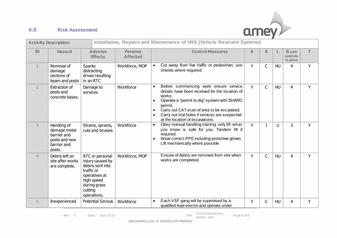
Rev: 5 Date: June 2019 Ref: STRU-Operations –
RAMS –023 Page 5 of 6
UNCONTROLLED IF COPIED OR PRINTED
9.0 Risk Assessment
Activity Description: Installation, Repairs and Maintenance of VRS (Vehicle Restraint Systems)
ID Hazard Adverse
Effects
Persons
Affected
Control Measures A S L R with
controls in place
T
1 Removal of damage sections of
beam and posts
Sparks distracting drives resulting
in an RTC
Workforce, MOP • Cut away from live traffic or pedestrian, use
shields where required. Y C HU 4 Y
2 Extraction of posts and
concrete bases.
Damage to
services
Workforce • Before commencing work ensure service
details have been received for the location of works.
• Operate a “permit to dig” system with SHARC
permit. • Carry out CAT scan of area to be excavated. • Carry out trial holes if services are suspected
at the location of excavations.
Y C HU 4 Y
3 Handling of damage metal barrier and posts and new barrier and
posts.
Strains, sprains,
cuts and bruises.
Workforce • Obey manual handling training, only lift what
you know is safe for you. Tandem lift if required.
• Wear correct PPE including protective gloves Lift mechanically where possible.
Y I U 3 Y
4 Debris left on site after works
are complete.
RTC or personal injury caused by debris sent into traffic or operatives at high speed during grass
cutting
operations.
Workforce, MOP Ensure of debris are removed from site when works are completed.
Y C HU 4 Y
5 Inexperienced Potential Serious Workforce • Each VSF gang will be supervised by a qualified lead erector and operate under
Y C HU 4 Y

Rev: 5 Date: June 2019 Ref: STRU-Operations –
RAMS –023 Page 6 of 6
UNCONTROLLED IF COPIED OR PRINTED
operatives or Fatal injuries and substantial
personal trauma
sector scheme 2a and b. All plant will be operated by suitably qualified and certified operatives.
6 Positional adjustment of
beams
Trapped fingers, cuts, bruises and
strains.
Workforce • Fingers should never be inserted into adjustment holes. Wear correct PPE and use correct hand tools.
Y I U 3 Y
7 Working in poor visibility or in
the dark.
Potential Serious or Fatal injuries and substantial
personal trauma
Workforce • Only work in areas of clear visibility. At night ensure appropriate task lighting for the works and the use of head torches for personal lighting.
Y C HU 4 Y
8 Vibrating Hand
Tools
Potential for
HAVS
Workforce In order to minimize the risk of HAVS by forcing the Pneumatic Wrenches to remove old bolts and nuts, old bolts and nuts must be ‘cracked’ manually prior to using a Pneumatic Wrench.
Y I U 3 Y
Assessor Name:
Key: A=ALARP insert Y or N, S=Sev erity (T / M / I / S / C), L=Likelihood (HU / U / L / VL / C), R=Risk Classification (1 / 2 / 3 / 4 / 5), T=Tolerable? Insert Y or N
redacted 11(2)
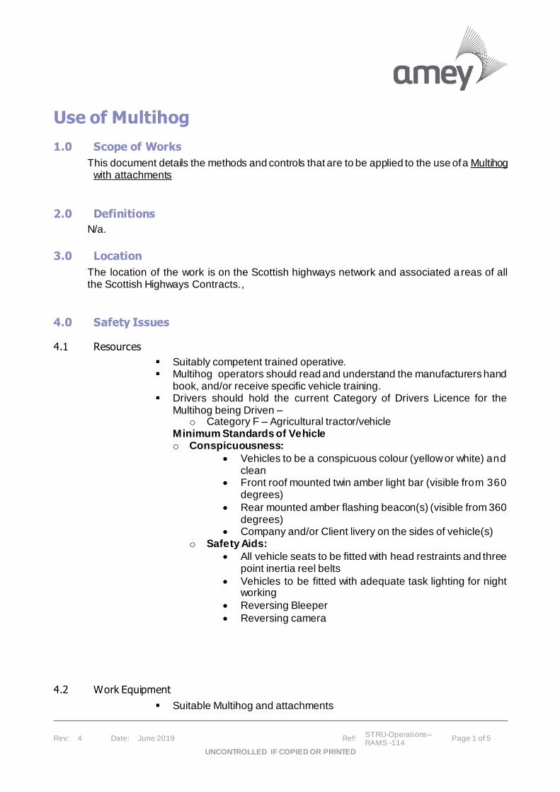
Rev: 4 Date: June 2019 Ref: STRU-Operations – RAMS -114
Page 1 of 5
UNCONTROLLED IF COPIED OR PRINTED
Use of Multihog
1.0 Scope of Works
This document details the methods and controls that are to be applied to the use ofa Multihog with attachments
2.0 Definitions
N/a.
3.0 Location
The location of the work is on the Scottish highways network and associated a reas of all the Scottish Highways Contracts.,
4.0 Safety Issues
4.1 Resources
▪ Suitably competent trained operative. ▪ Multihog operators should read and understand the manufacturers hand
book, and/or receive specific vehicle training. ▪ Drivers should hold the current Category of Drivers Licence for the
Multihog being Driven – o Category F – Agricultural tractor/vehicle
Minimum Standards of Vehicle o Conspicuousness:
• Vehicles to be a conspicuous colour (yellow or white) and clean
• Front roof mounted twin amber light bar (visible from 360 degrees)
• Rear mounted amber flashing beacon(s) (visible from 360 degrees)
• Company and/or Client livery on the sides of vehicle(s) o Safety Aids:
• All vehicle seats to be fitted with head restraints and three point inertia reel belts
• Vehicles to be fitted with adequate task lighting for night working
• Reversing Bleeper
• Reversing camera
4.2 Work Equipment
▪ Suitable Multihog and attachments

Rev: 4 Date: June 2019 Ref: STRU-Operations – RAMS -114
Page 2 of 5
UNCONTROLLED IF COPIED OR PRINTED
▪ Attachments : Cold milling planer, Grass cutting deck , Gritter , Filter drain harrow.
4.3 Materials
▪ Picks for planer and flails for grass cutting deck
4.4 Traffic or Pedestrian Management
• Suitable traffic management must be planned or in place for all Works
4.5 Work Restrictions
▪ N/a
4.6 Personal Protective Equipment (PPE)
▪ Hard Hat BS EN 397 ▪ Eye Protection BS EN 116 ▪ High Visibility Long Sleeve Jacket or Vest Class 3 BS EN 471 ▪ High Visibility Yellow Trousers Class 3 BS EN471 ▪ Steel Capped Safety Boots EN ISO 20347 ▪ Gloves BS EN 388 ▪ Ear Protection BS EN 352/SNR37
5.0 Method of Carrying out the works
Use of Multihog and attachments
• If practicable exit vehicle from side opposite to live traffic, if this is impracticable ensure you access and egress vehicles in safe gaps in the traffic.
• Do not walk or work between a Work Vehicle and live traffic
• All to wear clean long sleeve hi-visibility vests or coats and trousers
• Maintain maximum distance between yourself, your works Vehicle and live traffic
Welfare Facilities
• All vehicles should be fitted or equipped with:
• Emergency First Aid Kit • Fire Extinguisher
These should be checked regularly to ensure there presence and contents are adequate.
Pre-use Checks of work Area
o Works Site o Carry out a visual inspection of work area, and appraise the vehicle parking
and traffic management requirements, minimum requirements being o Provide a safe work area, by use of traffic management if not already
provided
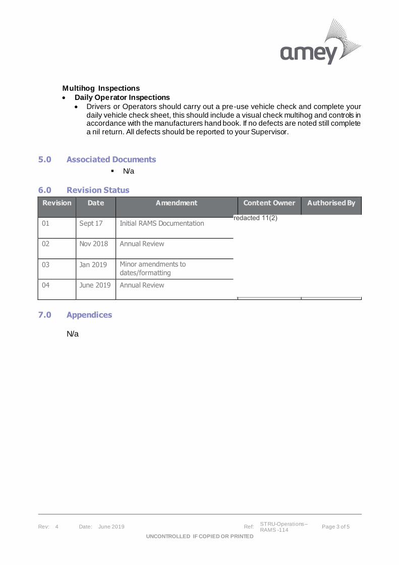
Rev: 4 Date: June 2019 Ref: STRU-Operations – RAMS -114
Page 3 of 5
UNCONTROLLED IF COPIED OR PRINTED
Multihog Inspections
• Daily Operator Inspections
• Drivers or Operators should carry out a pre-use vehicle check and complete your daily vehicle check sheet, this should include a visual check multihog and controls in accordance with the manufacturers hand book. If no defects are noted still complete a nil return. All defects should be reported to your Supervisor.
5.0 Associated Documents
▪ N/a
6.0 Revision Status
Revision
Date Amendment Content Owner Authorised By
01 Sept 17 Initial RAMS Documentation
02 Nov 2018 Annual Review
03 Jan 2019 Minor amendments to
dates/formatting
04 June 2019 Annual Review
7.0 Appendices
N/a
redacted 11(2)

Rev: 4 Date: June 2019 Ref: STRU-Operations –
RAMS -114 Page 4 of 5
UNCONTROLLED IF COPIED OR PRINTED
8.0 Risk Assessment
Activity Description: Multihog, Operation & Use
ID Hazard Adverse
Effects
Persons
Affected
Control Measures A S L R with
controls in place
T
1
In-correct
operation Lack of
training
Injuries crushing
impact entanglem
ent
Employees Public
• The Operator must be certified Lantra or similar standard by an approved organisation
and must be familiar with the Multihog to be used. Exposure to its use must be maintained, to ensure Operative continues skillset paired with Training/Assessment.
• Instruction in the use of the specific machine should be carried out by Multihog UK Ltd via their Lantra Approved Training Programme.
• The operator must be instructed and trained in the correct use of any attachment to the
machine (i.e. Planing Head, Flail Mower) • Change attachments as per Training and Multihog UK Ltd.’s recommendations.
• Ensure all quick hitch retaining pins are re-inserted correctly. Report any defects. • Ensure machine is stopped and standing on firm ground before changing the attachment
• Ensure power input matches required output to attachment (i.e. revolutions gauge
above Operatives head in cab)
Y I U 3 Y
2 Defective Equipment
Injuries
Cuts fractures
Employees
• Carry out and record daily checks on daily Defect Check sheet, report any defects to
your Supervisor. Submit form daily for records. • Daily Defect sheets must be carried out on all lifting (i.e. chains)/support (i.e. Dwangs)
equipment. • Operators should check for “next service due” and report if the date/hour are exceeded.
• Ensure there is a maintenance regime with after use clean and weekly maintenance
checks employed to ensure longevity of Plants life term and ability to operate safely and productively.
Y I U 3 Y
3 Crushing
Impact Injuries
.
Employees
Contractors Public
• Pedestrians/Non-Operating Staff must be kept clear of operations especially in proximity
of working equipment
• Warning beacons and alarms must operate when operating. • Windows and mirrors must be clean and cameras (if fitted) functional
• Audible reversing alarms and convex mirrors to provide 360 degree vision to be fitted.
• Deploy banks-person where visibility is limited or is restricted by load. • Never leave the machine with the engine running and the attachment raised, lower the
attachment to the ground, engage brakes and safety locks, remove the keys before leaving the machine
• carriage of passengers is not permitted
Y I U 3 Y
4 Slips, Trips
& Falls Minor Injuries
Employees
Contractors
• When connecting attachments the surface must be non-slippery (i.e. icy)
• Attachments must be stored correctly, preferably raised above ground (on pallet) to ensure
Y I U 3 Y
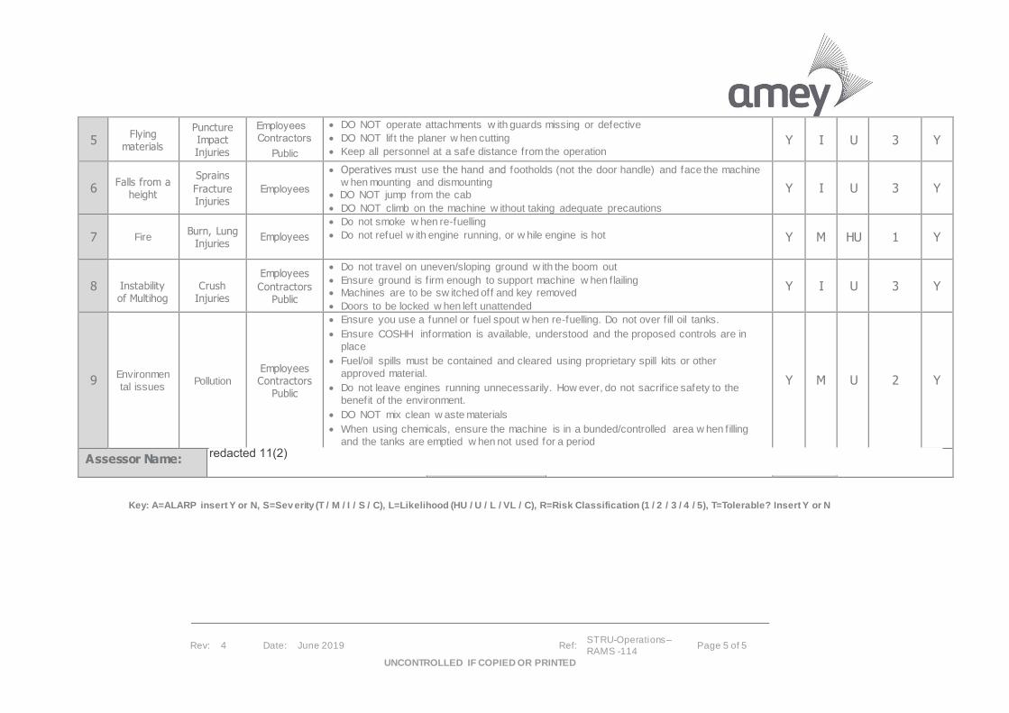
Rev: 4 Date: June 2019 Ref: STRU-Operations –
RAMS -114 Page 5 of 5
UNCONTROLLED IF COPIED OR PRINTED
5 Flying
materials
Puncture Impact Injuries
Employees
Contractors
Public
• DO NOT operate attachments w ith guards missing or defective
• DO NOT lif t the planer w hen cutting
• Keep all personnel at a safe distance from the operation Y I U 3 Y
6 Falls from a
height
Sprains
Fracture Injuries
Employees
• Operatives must use the hand and footholds (not the door handle) and face the machine
w hen mounting and dismounting • DO NOT jump from the cab
• DO NOT climb on the machine w ithout taking adequate precautions
Y I U 3 Y
7 Fire Burn, Lung
Injuries Employees
• Do not smoke w hen re-fuelling
• Do not refuel w ith engine running, or w hile engine is hot
Y M HU 1 Y
8
Instability of Multihog
Crush Injuries
Employees
Contractors Public
• Do not travel on uneven/sloping ground w ith the boom out
• Ensure ground is f irm enough to support machine w hen flailing
• Machines are to be sw itched off and key removed
• Doors to be locked w hen left unattended
Y I U 3 Y
9 Environmen
tal issues Pollution
Employees Contractors
Public
• Ensure you use a funnel or fuel spout w hen re-fuelling. Do not over f ill oil tanks.
• Ensure COSHH information is available, understood and the proposed controls are in
place
• Fuel/oil spills must be contained and cleared using proprietary spill kits or other
approved material.
• Do not leave engines running unnecessarily. How ever, do not sacrif ice safety to the
benefit of the environment.
• DO NOT mix clean w aste materials
• When using chemicals, ensure the machine is in a bunded/controlled area w hen filling
and the tanks are emptied w hen not used for a period
Y M U 2 Y
Assessor Name:
Key: A=ALARP insert Y or N, S=Sev erity (T / M / I / S / C), L=Likelihood (HU / U / L / VL / C), R=Risk Classification (1 / 2 / 3 / 4 / 5), T=Tolerable? Insert Y or N
redacted 11(2)

Rev: 5 Date: June 2019 Ref: STRU-Operations – RAMS -112
Page 1 of 6
UNCONTROLLED IF COPIED OR PRINTED
Use of Hot Box
1.0 Scope of Works
This document details the methods and controls that are to be applied to the use of a Hot Box
2.0 Definitions
N/a.
3.0 Location
The location of the work is on the highways network and associated areas of all the Scottish Highways Contracts
4.0 Safety Issues
4.1 Resources
▪ Suitably competent operative ▪ Hot Box operators should read and understand the manufacturers hand
book, and/or receive specific vehicle training. ▪ Drivers should hold the current Category of Drivers Licence for the hot
box being Driven – o Category C – Vehicles above 7.5 tonne
Minimum Standards of Vehicle o Conspicuousness:
• Vehicles to be a conspicuous colour (yellow or white) and clean
• Vehicles to show a ‘Highway Maintenance’ sticker • Vehicles to have Class 1 / microprismatic reflective
markings on the rear of the vehicle
• Front roof mounted twin amber light bar (visible from 360 degrees)
• Rear mounted amber flashing beacon(s) (visible from 360 degrees)
• Company and/or Client livery on the sides of vehicle(s)
• High-visibility strip along the sides of the vehicle o Safety Aids:
• All vehicle seats to be fitted with head restraints and three point inertia reel belts
• Vehicles to be fitted with adequate task lighting for night working
• Reversing Bleeper
• Reversing CCTV and monitor
Rev: 5 Date: June 2019 Ref: STRU-Operations – RAMS -112
Page 2 of 6
UNCONTROLLED IF COPIED OR PRINTED
4.2 Work Equipment
▪ Suitable Hot Box
4.3 Materials
▪ Leoclean degreaser
4.4 Traffic or Pedestrian Management
• Suitable traffic management must be planned or in place for all Works
4.5 Work Restrictions
▪ N/a
4.6 Personal Protective Equipment (PPE)
▪ Hard Hat BS EN 397 ▪ Eye Protection BS EN 116 ▪ High Visibility Long Sleeve Jacket or Vest Class 3 BS EN 471 ▪ High Visibility Yellow Trousers Class 3 BS EN471 ▪ Steel Capped Safety Boots EN ISO 20347 ▪ Gloves BS EN 388 ▪ Ear Protection BS EN 352/SNR37
5.0 Method of Carrying out the works
Use of Hot Box
• If practicable exit vehicle from side opposite to live traffic, if this is impracticable ensure you access and egress vehicles in safe gaps in the traffic.
• Do not walk or work between a Work Vehicle and live traffic
• All to wear clean long sleeve hi-visibility vests or coats and trousers
• Maintain maximum distance between yourself, your works Vehicle and live traffic • Before setting off check Gas Cylinders are properly secured and all valves set
securely in the off position. Ensure they have sufficient supply to complete works.
• Place any empty Gas bottles in the secure cages and inform your supervisor. • When you arrive at the Quarry, ensure the heater is switched on and sufficient
time has passed to allow the heater to retain the heat before the hotbox is fil led.
• Access rear platform of Hotbox at Back of cab and open the double covers to accept the Asphalt.
• Drive under the coating plant to the marked position, stop where indicated and apply handbrake and wait for load to be poured.
• Await for signal to indicate load complete and pull away to a safe area. Check and clean up any spillage.
• Take care during access and egress to and from the Hotbox platform and close covers on hotbox securely.

Rev: 5 Date: June 2019 Ref: STRU-Operations – RAMS -112
Page 3 of 6
UNCONTROLLED IF COPIED OR PRINTED
• Go to site and position auger appropriate to the patch and always use a Banksman when reversing.
• Before operating Auger the PTO must be engaged, therefore ensure the clutch is fully depressed when you switch the PTO on then release the clutch slowly.
• When pouring directly from the Auger ensure it correctly positioned central to the patch, then release locking pin on the chute attached to the Auger and align to the patch.
• Before release of material from Hotbox stand clear and ensure all other operatives are clear of the chute and the pouring area.
• Once clear apply the on button to release the material, keep a close eye on the quantity being released and switch to off when the desired quantity of material has been released.
• Fold up chute and re-insert locking pin securely. • Before you move the vehicle the PTO must be disengaged, ensure the clutch is
depressed thoroughly switch the PTO to off and slowly release the clutch.
• Repeat this process for other patches as you go.
• Once patching is complete, check the chute, doors, tools and equipment are secure and all patches are measured and recorded and return to depot.
Welfare Facilities
• All vehicles should be fitted or equipped with: • Emergency First Aid Kit
• Fire Extinguisher These should be checked regularly to ensure there presence and contents are adequate.
Pre-use Checks of work Area
o Works Site o Carry out a visual inspection of work area, and appraise the vehicle parking
and traffic management requirements, minimum requirements being o Provide a safe work area, by use of traffic management if not already
provided
Hot Box Inspections
• Daily Operator Inspections Drivers or Operators should carry out a pre-use vehicle check and complete your daily vehicle check sheet, this should include a visual check of the hot box and controls in accordance with the manufacturers hand book. If no defects are noted still complete a nil return. All defects should be reported to your Supervisor.
Hot Box Cleaning
• At no point, should an operative be expected to clean the hot box by standing on top of the hot box unit.
• Reverse vehicle to spoil bay using approved procedure utilizing banksperson if required
• Turn on auger to remove excessive material using the chute before turning off pr ior to next stage
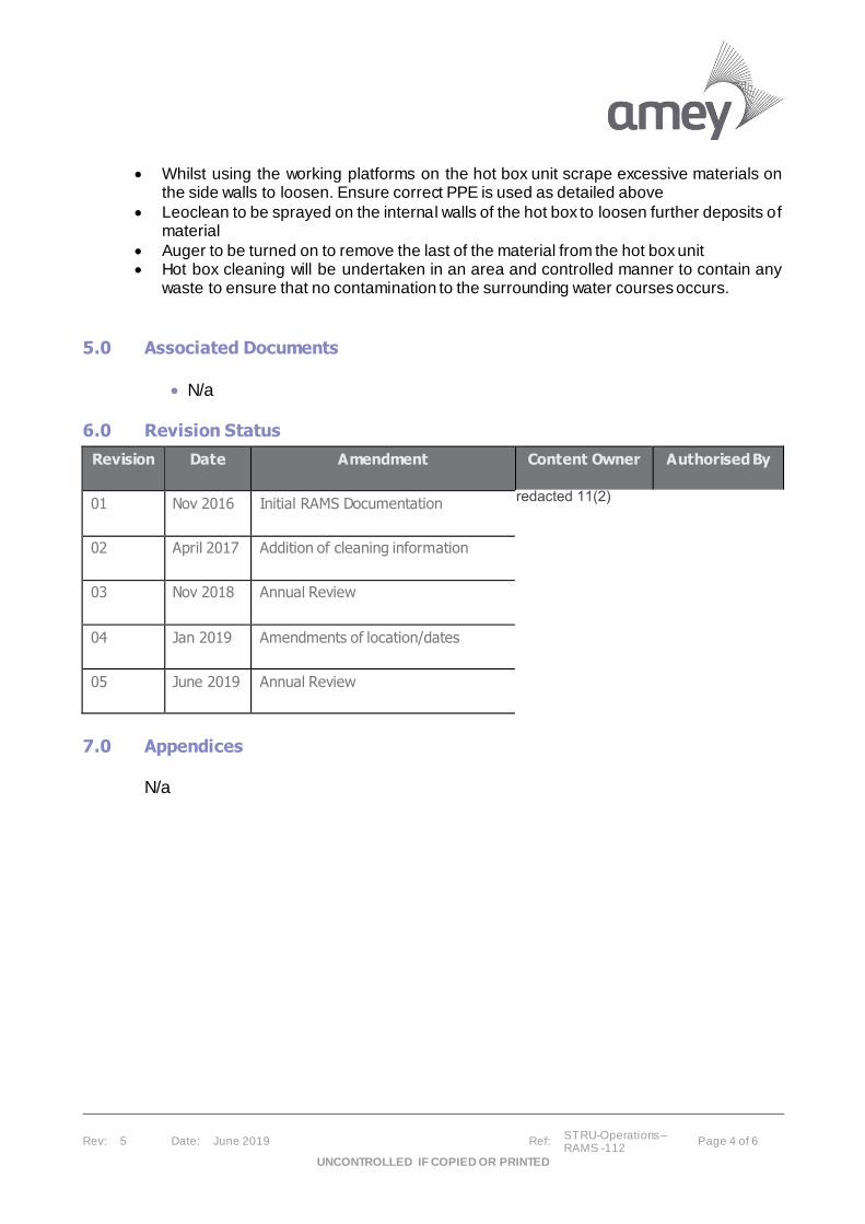
Rev: 5 Date: June 2019 Ref: STRU-Operations – RAMS -112
Page 4 of 6
UNCONTROLLED IF COPIED OR PRINTED
• Whilst using the working platforms on the hot box unit scrape excessive materials on the side walls to loosen. Ensure correct PPE is used as detailed above
• Leoclean to be sprayed on the internal walls of the hot box to loosen further deposits of material
• Auger to be turned on to remove the last of the material from the hot box unit • Hot box cleaning will be undertaken in an area and controlled manner to contain any
waste to ensure that no contamination to the surrounding water courses occurs.
5.0 Associated Documents
• N/a
6.0 Revision Status
Revision
Date Amendment Content Owner Authorised By
01 Nov 2016 Initial RAMS Documentation
02 April 2017 Addition of cleaning information
03 Nov 2018 Annual Review
04 Jan 2019 Amendments of location/dates
05 June 2019 Annual Review
7.0 Appendices
N/a
redacted 11(2)
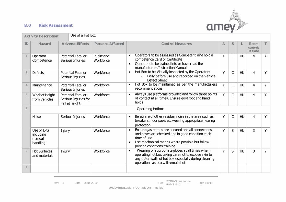
Rev: 5 Date: June 2019 Ref: STRU-Operations –
RAMS -112 Page 5 of 6
UNCONTROLLED IF COPIED OR PRINTED
8.0 Risk Assessment
Activity Description: Use of a Hot Box
ID Hazard Adverse Effects Persons Affected Control Measures A S L R with
controls in place
T
1 Operator
Competence
Potential Fatal or
Serious Injuries
Public and
Workforce
• Operators to be assessed as Competent, and hold a competence Card or Certificate
• Operators to be trained into or have read the manufacturers Instruction Manual
Y C HU 4 Y
3 Defects Potential Fatal or
Serious Injuries
Workforce • Hot Box to be Visually inspected by the Operator:
o Daily before use and recorded on the Vehicle Defect Sheet
Y C HU 4 Y
4 Maintenance Potential Fatal or
Serious Injuries
Workforce • Hot Box to be maintained as per the manufacturers recommendations
Y C HU 4 Y
5 Work at Height
from Vehicles
Potential Fatal or Serious Injuries for
Fall at height
Workforce • Always use platforms provided and follow three points of contact at all times. Ensure goot foot and hand holds
Y C HU 4 Y
6
Operating Hotbox
Noise Serious Injuries Workforce • Be aware of other residual noise in the area such as breakers, floor saws etc wearing appropriate hearing
protection
Y C HU 4 Y
Use of LPG including manual
handling
Injury Workforce • Ensure gas bottles are secured and all connections and hoses are checked and in good condition each time of use
• Use mechanical means where possible but follow pristine conditions training
Y S HU 3 Y
7 Hot Surfaces
and materials
Injury Workforce • Wearing of appropriate gloves at all times when operating hot box taking care not to expose skin to any outer walls of hot box especially during cleaning operations as box will remain hot
Y S HU 3 Y
8

Rev: 5 Date: June 2019 Ref: STRU-Operations –
RAMS -112 Page 6 of 6
UNCONTROLLED IF COPIED OR PRINTED
Assessor Name:
Key: A=ALARP insert Y or N, S=Sev erity (T / M / I / S / C), L=Likelihood (HU / U / L / VL / C), R=Risk Classification (1 / 2 / 3 / 4 / 5), T=Tolerable? Insert Y or N
redacted 11(2)

Diack & Macaulay Ltd Construction AMEY M8 Jct4 Superstructure
Strike through Risk Assessments red not valid, green valid RISK ASSESSMENT – INDEX
1 WORK FROM LADDERS 68 SLIPS AND TRIPS
2 USE OF MATERIAL HOIST 69 SPILLAGES
3 LIFTING OPERATIONS 71 SNOW CLEARANCE
4 USE AND STORAGE OF PALLETISED BRICK 72 TRAFFIC MOVEMENTS
8 USE OF ABRASIVE WHEELS / STIHL SAWS 73 TREE FELLING
11 BURIED SERVICES 75 UNDERGROUND AND OVERHEAD SERVICES
12 CEMENT AND CONCRETE WORKS 76 USE OF CARTRIDGE TOOLS
13 USE OF COMPRESSED AIR / PNEUMATIC TOOLS 78 USE OF COMPRESSOR
14 WORK IN CONFINED / RESTRICTED SPACES 79 USE OF EXCAVATORS
15 WORK IN CONTAMINATED GROUND 80 USE OF DRILLS
16 WELDING FUME 81 USE OF ELECTRICAL EQUIPMENT
17 DEEP EXCAVATION WORK 83 USE OF HAND HELD GRINDERS
18 DEMOLITION WORK 86 USE OF PAINTS, ADHESIVES and THINNERS
19 USE OF DUMPER TRUCK 87 USE OF PETROL or DIESEL
24 EXCAVATIONS 89 USE OF POWER SAW
25 EXPOSURE TO LIVE SERVICES 90 USE OF PPE
26 EXPOSURE TO VIOLENCE 93 USE OF TAR/BITUMEN BOILER
27 GROUND WORKERS – FALLING OBJECTS 98 WORK IN ADVERSE WEATHER CONDITIONS
28 FIRE RISK DURING DEMOLITION WORKS 101 WORK NEAR ROADWAYS
31 GENERAL ACTIVITIES – DUSTS 102 WORK NEAR WATERCOURSES
32 GENERAL CLEANING DUTIES 103 WORK WITH HAZARDOUS SUBSTANCES
33 GENERAL OFFICE ACTIVITIES 110 VEHICLE COLLISION
36 USE OF TOWER SCAFFOLD 113 REFUELLING OPERATIONS
37 OPERATION OF FORK LIFT TRUCKS
39 MOBILE PLANT OPERATIONS
42 LOADING & UNLOADING OF VEHICLES
43 WORK AT HEIGHT
44 USE OF POWER TOOLS
45 USE OF MANUAL/HAND TOOLS
51 WELDING
52 HOT WORKS
61 MINOR DEMOLITIONS
63 NOISE
64 ROAD SWEEPING – GULLY CLEARING
65 SAFETY AT ROADWORKS
66 SEWER AND DRAINAGE WORKS
67 SITE SECURITY
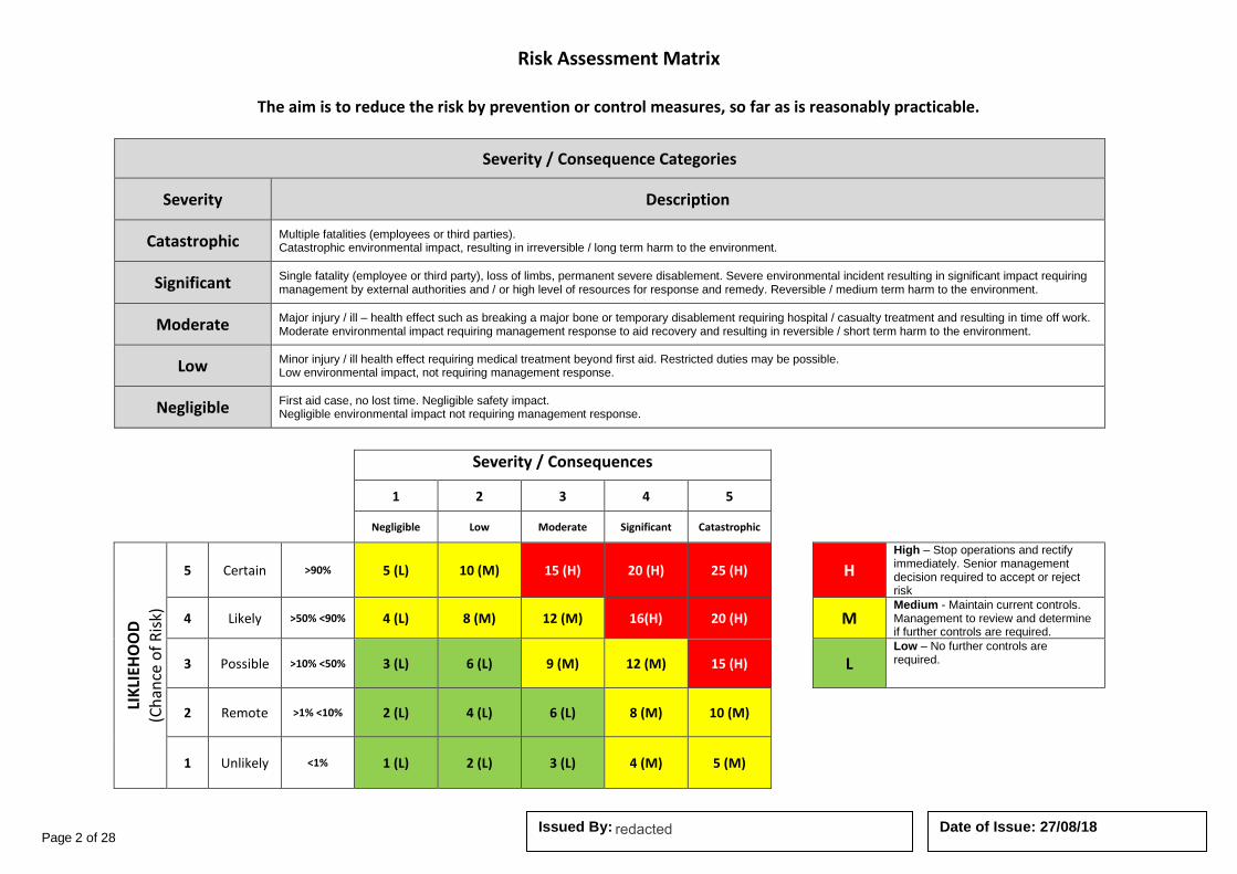
Page 2 of 28 Date of Issue: 27/08/18 Issued By:
Risk Assessment Matrix
The aim is to reduce the risk by prevention or control measures, so far as is reasonably practicable.
Severity / Consequence Categories
Severity Description
Catastrophic Multiple fatalities (employees or third parties). Catastrophic environmental impact, resulting in irreversible / long term harm to the environment.
Significant Single fatality (employee or third party), loss of limbs, permanent severe disablement. Severe environmental incident resulting in significant impact requiring management by external authorities and / or high level of resources for response and remedy. Reversible / medium term harm to the environment.
Moderate Major injury / ill – health effect such as breaking a major bone or temporary disablement requiring hospital / casualty treatment and resulting in time off work. Moderate environmental impact requiring management response to aid recovery and resulting in reversible / short term harm to the environment.
Low Minor injury / ill health effect requiring medical treatment beyond first aid. Restricted duties may be possible. Low environmental impact, not requiring management response.
Negligible First aid case, no lost time. Negligible safety impact. Negligible environmental impact not requiring management response.
Severity / Consequences
1 2 3 4 5
Negligible Low Moderate Significant Catastrophic
LIK
LIEH
OO
D
(Ch
ance
of
Ris
k)
5 Certain >90% 5 (L) 10 (M) 15 (H) 20 (H) 25 (H)
H High – Stop operations and rectify immediately. Senior management decision required to accept or reject risk
4 Likely >50% <90% 4 (L) 8 (M) 12 (M) 16(H) 20 (H)
M Medium - Maintain current controls. Management to review and determine if further controls are required.
3 Possible >10% <50% 3 (L) 6 (L) 9 (M) 12 (M) 15 (H)
L Low – No further controls are required.
2 Remote >1% <10% 2 (L) 4 (L) 6 (L) 8 (M) 10 (M)
1 Unlikely <1% 1 (L) 2 (L) 3 (L) 4 (M) 5 (M)
redacted 11(2)

Page 3 of 28 Date of Issue: 27/08/18 Issued By:
Diack & Macaulay Ltd - Risk Assessment
TASK: LIFTING OPERATIONS RA Reference No RA - 0003
Location: Amey M8 Jct4 Superstructure Works Assessed By: Date of Assessment
19th August 2019
Hazard Consequences Persons Affected
Seve
rity
Like
liho
od
Tota
l Ris
k
Existing Control Measures Additional Control Measures
(where appropriate)
Residual Risk
Seve
rity
Like
liho
od
Tota
l Ris
k
Defective / inadequate
equipment
Incorrect positioning
Working within lane closure
Unsuitable base
Overhead cables and
other obstructions
Insecure load
Swinging load
Weather conditions
Injuries to operative,
other trades, members of the public and or
visitors including minor to fatal.
Damage to plant and or premises
Operatives.
Third Parties (Client, Contractor, Visitors, other trades on site)
4 4
16 H
Suitable certification to be provided and necessary inspections carried out
Safe working area to be provided for operation of equipment
Trained operator and banksman to be used
Hi-visibility clothing to be worn by banksman as well as other P.P.E.
Ensure loads are not excessive and that they are properly secured Ensure correct and certified lifting equipment in use
Stop work in adverse weather conditions Lifting plan to be created.
Other operatives to be kept clear of operation
Supervisor / Manager to carry out checks to ensure
Operatives are using controls.
Exclusion zone erected and enforced during lifting
operation
Ensure all operatives are familiar with this risk
assessment
Edge restraints to be used on high sided vehicles
No lifting over live
carriageway
Toolbox Talks, Safety Briefings, Alert Bulletins.
4 1
4 L
PPE Requirements
Description Head Protection Eye Protection Hearing
Protection Protective Footwear
Hi Visibility Clothing
Hand Protection Respiratory Protection
Protective Coveralls
Safety Harness Face Protection
redacted 11(2)
redacted 11(2)

Page 4 of 28 Date of Issue: 27/08/18 Issued By:
Diack & Macaulay Ltd - Risk Assessment
TASK: Use of Abrasive Wheels / Still Saws RA Reference No RA - 0008
Location: Amey M8 Jct4 Superstructure Works Assessed By: Date of Assessment
19th August 2019
Hazard Consequences Persons Affected
Seve
rity
Like
liho
od
Tota
l Ris
k
Existing Control Measures Additional Control
Measures (where appropriate)
Residual Risk
Seve
rity
Like
liho
od
Tota
l Ris
k
Noise / vibration Working adjacent to live carriageway Hotwork Dust Fire Contact with moving parts Bursting of discs Electricity / fumes Unpredictable movement
Vibration related illness Noise induced hearing loss Respiratory issues Cuts – potentially major Amputation Electric shock, burns, death Musculo-skeletal injury Electric Shock, contact with moving parts.
Operatives.
Third Parties (Client, Contractor, Visitors, other trades on site )
4 4
16 H
Trained operative Restricted duration / work rotation, personnel HAVS books to be completed Dust suppression used at all times Hearing protection to be used at all times Eye protection to be used at all times. FFP3 Dust mask, face fitted to the user to be used at all times. Condition of tools checked before use Loose clothing to be avoided Tool to be firmly gripped / supported Defective equipment to be withdrawn from service Combustible material to be removed or protected and
fire extinguisher to hand when grinding or cutting
materials liable to spark.
Supervisor / Manager to carry out checks to ensure
Operatives are using controls.
Awareness of surrounding
environment public and traffic
Ensure all operatives are familiar with this risk
assessment
Toolbox Talks, Safety Briefings, Alert Bulletins.
3 3
9 M
PPE Requirements
Description Head Protection Eye Protection Hearing
Protection Protective Footwear
Hi Visibility Clothing
Hand Protection Respiratory Protection
Protective Coveralls
Safety Harness Face Protection
Fire Extinguisher
Description WATER POWDER FOAM CO2
redacted 11(2)
redacted 11(2)
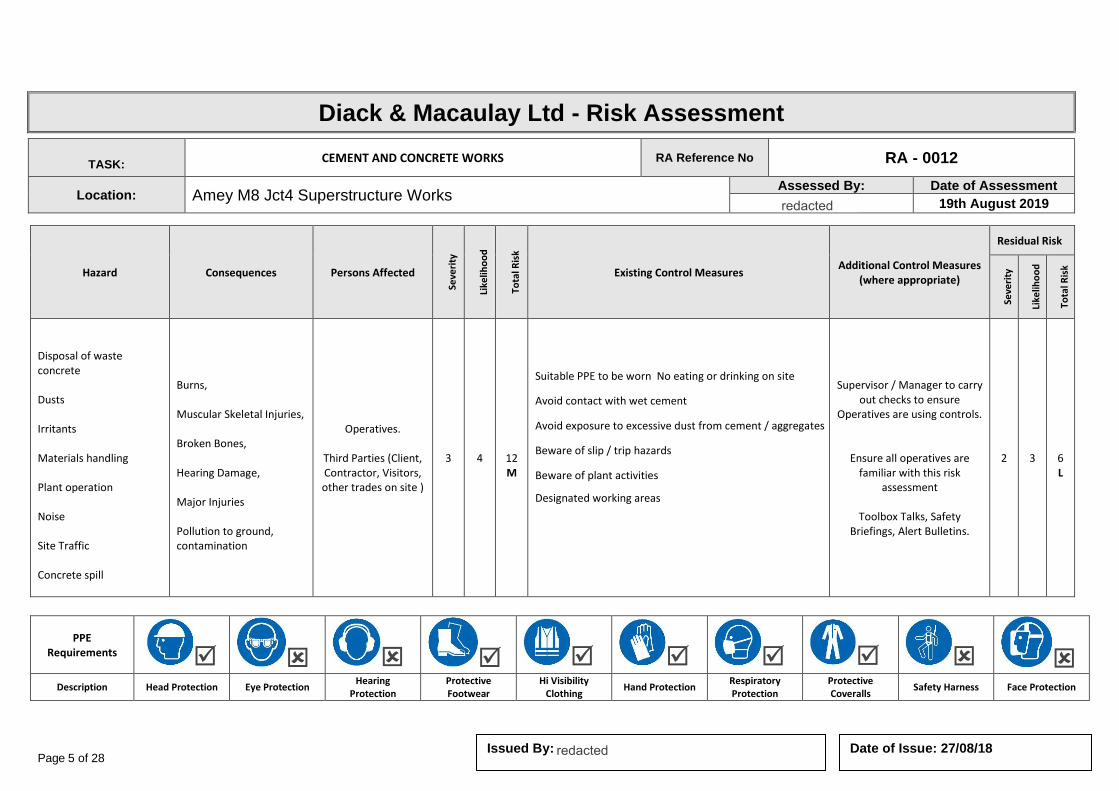
Page 5 of 28 Date of Issue: 27/08/18 Issued By:
Diack & Macaulay Ltd - Risk Assessment
TASK: CEMENT AND CONCRETE WORKS RA Reference No RA - 0012
Location: Amey M8 Jct4 Superstructure Works Assessed By: Date of Assessment
19th August 2019
Hazard Consequences Persons Affected
Seve
rity
Like
liho
od
Tota
l Ris
k
Existing Control Measures Additional Control Measures
(where appropriate)
Residual Risk
Seve
rity
Like
liho
od
Tota
l Ris
k
Disposal of waste concrete Dusts Irritants Materials handling Plant operation Noise Site Traffic Concrete spill
Burns, Muscular Skeletal Injuries, Broken Bones, Hearing Damage, Major Injuries Pollution to ground, contamination
Operatives.
Third Parties (Client, Contractor, Visitors, other trades on site )
3 4
12 M
Suitable PPE to be worn No eating or drinking on site
Avoid contact with wet cement
Avoid exposure to excessive dust from cement / aggregates
Beware of slip / trip hazards
Beware of plant activities
Designated working areas
Supervisor / Manager to carry out checks to ensure
Operatives are using controls.
Ensure all operatives are familiar with this risk
assessment
Toolbox Talks, Safety Briefings, Alert Bulletins.
2 3
6 L
PPE Requirements
Description Head Protection Eye Protection Hearing
Protection Protective Footwear
Hi Visibility Clothing
Hand Protection Respiratory Protection
Protective Coveralls
Safety Harness Face Protection
redacted 11(2)
redacted 11(2)

Page 6 of 28 Date of Issue: 27/08/18 Issued By:
Diack & Macaulay Ltd - Risk Assessment
TASK: USE OF COMPRESSED AIR / PNEUMATIC TOOLS RA Reference No RA - 0013
Location: Amey M8 Jct4 Superstructure Works Assessed By: Date of Assessment
19th August 2019
Hazard Consequences Persons Affected
Seve
rity
Like
liho
od
Tota
l Ris
k
Existing Control Measures Additional Control Measures
(where appropriate)
Residual Risk
Seve
rity
Like
liho
od
Tota
l Ris
k
Noise Pressurised equipment Unpredictable movement Vibration HAVS
Hearing Damage, Vibration white finger Pressure injection injuries Operatives.
Third Parties (Client, Contractor, Visitors, other trades on site )
3 4
12 M
HAVS risk assessment
Limited use of compressed air equipment Subject to regular testing of compressor and system Condition of tools checked before use Tool to be firmly gripped / supported Defective equipment to be withdrawn from service Operatives trained and competent Advised against blow down of clothing etc.
Supervisor / Manager to carry out checks to ensure
Operatives are using controls.
Ensure all operatives are familiar with this risk
assessment
Toolbox Talks, Safety Briefings, Alert Bulletins.
2 3
6 L
PPE Requirements
Description Head Protection Eye Protection Hearing
Protection Protective Footwear
Hi Visibility Clothing
Hand Protection Respiratory Protection
Protective Coveralls
Safety Harness Face Protection
redacted 11(2)
redacted 11(2)
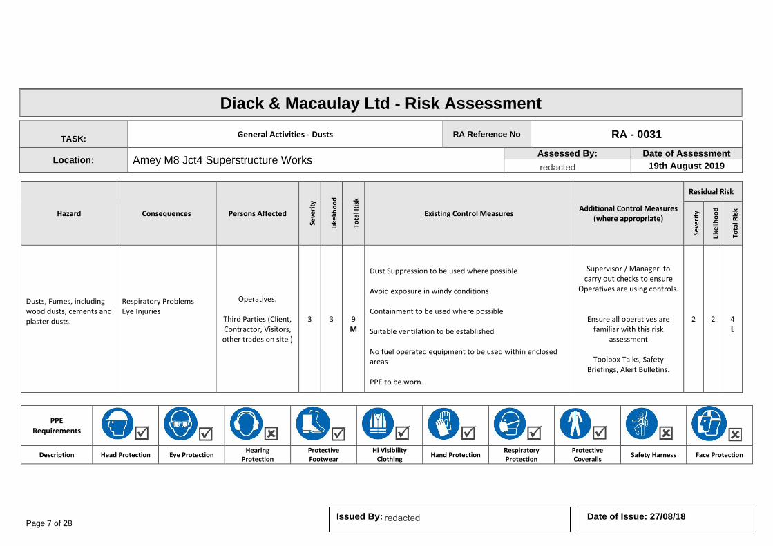
Page 7 of 28 Date of Issue: 27/08/18 Issued By:
Diack & Macaulay Ltd - Risk Assessment
TASK: General Activities - Dusts RA Reference No RA - 0031
Location: Amey M8 Jct4 Superstructure Works Assessed By: Date of Assessment
19th August 2019
Hazard Consequences Persons Affected
Seve
rity
Like
liho
od
Tota
l Ris
k
Existing Control Measures Additional Control Measures
(where appropriate)
Residual Risk
Seve
rity
Like
liho
od
Tota
l Ris
k
Dusts, Fumes, including wood dusts, cements and plaster dusts.
Respiratory Problems Eye Injuries
Operatives.
Third Parties (Client, Contractor, Visitors, other trades on site )
3 3
9 M
Dust Suppression to be used where possible Avoid exposure in windy conditions Containment to be used where possible Suitable ventilation to be established No fuel operated equipment to be used within enclosed areas PPE to be worn.
Supervisor / Manager to carry out checks to ensure
Operatives are using controls.
Ensure all operatives are familiar with this risk
assessment
Toolbox Talks, Safety Briefings, Alert Bulletins.
2 2
4 L
PPE Requirements
Description Head Protection Eye Protection Hearing
Protection Protective Footwear
Hi Visibility Clothing
Hand Protection Respiratory Protection
Protective Coveralls
Safety Harness Face Protection
redacted 11(2)
redacted 11(2)

Page 8 of 28 Date of Issue: 27/08/18 Issued By:
Diack & Macaulay Ltd - Risk Assessment
TASK: MOBILE PLANT OPERATIONS RA Reference No RA - 0039
Location: Amey M8 Jct4 Superstructure Works Assessed By: Date of Assessment
19th August 2019
Hazard Consequences Persons Affected
Seve
rity
Like
liho
od
Tota
l Ris
k
Existing Control Measures Additional Control Measures
(where appropriate)
Residual Risk
Seve
rity
Like
liho
od
Tota
l Ris
k
Plant overturning Plant movement/ contact with moving machinery Trapping/Falling materials/unintentional collapse Overhead/underground services Contact with persons, structures, etc Slip, trips, falls from plant Noise, vibration, dust, debris, fume Leaks, spills
Fatality Major injuries Damage to plant Electrocution Damage to grid Down time Health problems due to vibration Respiratory problems Ground contamination
Operatives.
Third Parties (Client, Contractor, Visitors, other trades on site )
4 4
16 H
Plant and operators certification to be checked Banksman to be used at all times and communication established Lifting operations to be suitably planned Areas to be cordoned off, prepared for plant movement and lifting activities Protection to be provided for underground / overhead services All non essential persons to be withdrawn from area Keys to be removed and kept with operative at all times Daily operational checks to be carried out and safety checks undertaken
Routine maintenance of equipment
Supervisor / Manager to carry out checks to ensure
Operatives are using controls.
Ensure all operatives are familiar with this risk
assessment
Toolbox Talks, Safety Briefings, Alert Bulletins.
3 3
6 M
PPE Requirements
Description Head Protection Eye Protection Hearing
Protection Protective Footwear
Hi Visibility Clothing
Hand Protection Respiratory Protection
Protective Coveralls
Safety Harness Face Protection
redacted 11(2)
redacted 11(2)
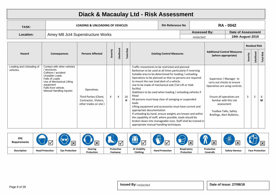
Page 9 of 28 Date of Issue: 27/08/18 Issued By:
Diack & Macaulay Ltd - Risk Assessment
TASK: LOADING & UNLOADING OF VEHICLES RA Reference No RA - 0042
Location: Amey M8 Jct4 Superstructure Works Assessed By: Date of Assessment
19th August 2019
Hazard Consequences Persons Affected
Seve
rity
Like
liho
od
Tota
l Ris
k
Existing Control Measures Additional Control Measures
(where appropriate)
Residual Risk
Seve
rity
Like
liho
od
Tota
l Ris
k
Loading and Unloading of
vehicles. Contact with other vehicles / structures Collision / accident Unstable Loads Falls of Loads Use of Mechanical Lifting equipment Falls from vehicle. Manual Handling Injuries Operatives.
Third Parties (Client, Contractor, Visitors, other trades on site )
4 4
16 H
Traffic movements to be restricted and planned Banksman to be used at all times particularly if reversing Suitable area to be determined for loading / unloading Operations to be planned so that no persons are required to mount the rear load deck of a vehicle. Use to be made of mechanical aids (Tail Lift or Hiab facility) Stabilisers to be used when loading / unloading vehicles if fitted All persons must keep clear of swinging or suspended loads Lifting equipment and accessories must have current and appropriate documentation If unloading by hand, ensure weights are known and within the capability of staff, where possible, loads should be broken down into manageable sizes. Staff shall be trained in appropriate manual handling techniques.
Supervisor / Manager to carry out checks to ensure
Operatives are using controls.
Ensure all operatives are familiar with this risk
assessment
Toolbox Talks, Safety Briefings, Alert Bulletins.
3 3
6 M
PPE Requirements
Description Head Protection Eye Protection Hearing
Protection Protective Footwear
Hi Visibility Clothing
Hand Protection Respiratory Protection
Protective Coveralls
Safety Harness Face Protection
redacted 11(2)
redacted 11(2)

Page 10 of 28 Date of Issue: 27/08/18 Issued By:
Diack & Macaulay Ltd - Risk Assessment
TASK: USE OF POWER TOOLS RA Reference No RA - 0044
Location: Amey M8 Jct4 Superstructure Works Assessed By: Date of Assessment
19th August 2019
Hazard Consequences Persons Affected
Seve
rity
Like
liho
od
Tota
l Ris
k
Existing Control Measures Additional Control Measures
(where appropriate)
Residual Risk
Seve
rity
Like
liho
od
Tota
l Ris
k
USE OF POWER TOOLS
•Electric shock due to faulty equipment •Physical injury to user through improper use •Hand arm vibration injury
Operatives.
Third Parties (Client, Contractor, Visitors, other trades on site )
4 5
20 H
All equipment PAT tested in accordance with current legislation Visual checks to be carried out before use for any obvious signs of damage No 240 volt tools to be used. All tools either 110 volt or battery operated to reduce risk of serious injury All operatives have received health & safety training Operatives should make themselves familiar with the operating instructions of all power tools
Supervisor / Manager to carry out checks to ensure
Operatives are using controls.
Ensure all operatives are familiar with this risk
assessment
Toolbox Talks, Safety Briefings, Alert Bulletins.
4 3
12 M
PPE Requirements
Description Head Protection Eye Protection Hearing
Protection Protective Footwear
Hi Visibility Clothing
Hand Protection Respiratory Protection
Protective Coveralls
Safety Harness Face Protection
redacted 11(2)
redacted 11(2)

Page 11 of 28 Date of Issue: 27/08/18 Issued By:
Diack & Macaulay Ltd - Risk Assessment
TASK: USE OF MANUAL/HAND TOOLS RA Reference No RA - 0045
Location: Amey M8 Jct4 Superstructure Works Assessed By: Date of Assessment
19th August 2019
Hazard Consequences Persons Affected
Seve
rity
Like
liho
od
Tota
l Ris
k
Existing Control Measures Additional Control Measures
(where appropriate)
Residual Risk
Seve
rity
Like
liho
od
Tota
l Ris
k
Use of manual tools Possible injury to user or persons adjacent if grip of tool becomes loose or though improper use. Operatives.
Third Parties (Client, Contractor, Visitors, other trades on site )
4 3
12 M
All operatives have received full health & safety training All operatives have been issued with all necessary PPE
Supervisor / Manager to carry out checks to ensure
Operatives are using controls.
Ensure all operatives are familiar with this risk
assessment
Toolbox Talks, Safety Briefings, Alert Bulletins.
2 2
4 L
PPE Requirements
Description Head Protection Eye Protection Hearing
Protection Protective Footwear
Hi Visibility Clothing
Hand Protection Respiratory Protection
Protective Coveralls
Safety Harness Face Protection
redacted 11(2)
redacted 11(2)

Page 12 of 28 Date of Issue: 27/08/18 Issued By:
Diack & Macaulay Ltd - Risk Assessment
TASK: HOT WORKS RA Reference No RA - 0052
Location: Amey M8 Jct4 Superstructure Works Assessed By: Date of Assessment
19th August 2019
Hazard Consequences Persons Affected
Seve
rity
Like
liho
od
Tota
l Ris
k
Existing Control Measures Additional Control Measures
(where appropriate)
Residual Risk
Seve
rity
Like
liho
od
Tota
l Ris
k
Hot work Fire
Burns Smoke Inhalation Fume.
Operatives.
Third Parties (Client, Contractor, Visitors, other trades on site )
4 4
16 H
P.P.E. – protective gloves / workwear /etc Extinguishers available next to the worksite Flammable materials removed / protected Adequate ventilation Permits for hotwork where appropriate Gas torched never to be left unattended whilst ignited Ensure nothing is alight before leaving working area Think of fire triangle i.e. source of ignition, fuel and oxygen – try to keep the 3 from coming together in the same place. Ensure other ‘fuels’ are not in close proximity. Store in accordance with manufacturers guidelines.
Supervisor / Manager to carry out checks to ensure Operatives
are using controls.
Ensure all operatives are familiar with this risk assessment
Toolbox Talks, Safety Briefings,
Alert Bulletins.
2 2
4 L
PPE Requirements
Description Head Protection Eye Protection Hearing
Protection Protective Footwear
Hi Visibility Clothing
Hand Protection Respiratory Protection
Protective Coveralls
Safety Harness Face Protection
Fire Extinguisher
Description WATER POWDER FOAM CO2
redacted 11(2)
redacted 11(2)
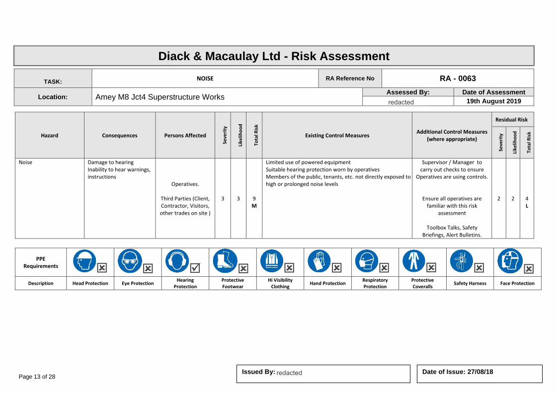
Page 13 of 28 Date of Issue: 27/08/18 Issued By:
Diack & Macaulay Ltd - Risk Assessment
TASK: NOISE RA Reference No RA - 0063
Location: Amey M8 Jct4 Superstructure Works Assessed By: Date of Assessment
19th August 2019
Hazard Consequences Persons Affected
Seve
rity
Like
liho
od
Tota
l Ris
k
Existing Control Measures Additional Control Measures
(where appropriate)
Residual Risk
Seve
rity
Like
liho
od
Tota
l Ris
k
Noise Damage to hearing Inability to hear warnings, instructions
Operatives.
Third Parties (Client, Contractor, Visitors, other trades on site )
3 3
9 M
Limited use of powered equipment Suitable hearing protection worn by operatives Members of the public, tenants, etc. not directly exposed to high or prolonged noise levels
Supervisor / Manager to carry out checks to ensure
Operatives are using controls.
Ensure all operatives are familiar with this risk
assessment
Toolbox Talks, Safety Briefings, Alert Bulletins.
2 2
4 L
PPE Requirements
Description Head Protection Eye Protection Hearing
Protection Protective Footwear
Hi Visibility Clothing
Hand Protection Respiratory Protection
Protective Coveralls
Safety Harness Face Protection
redacted 11(2)
redacted 11(2)

Page 14 of 28 Date of Issue: 27/08/18 Issued By:
Diack & Macaulay Ltd - Risk Assessment
TASK: SAFETY AT ROADWORKS RA Reference No RA - 0065
Location: Amey M8 Jct4 Superstructure Works Assessed By: Date of Assessment
19th August 2019
Hazard Consequences Persons Affected
Seve
rity
Like
liho
od
Tota
l Ris
k
Existing Control Measures Additional Control Measures
(where appropriate)
Residual Risk
Seve
rity
Like
liho
od
Tota
l Ris
k
Road traffic
Being struck by plant vehicles or other road traffic
Operatives.
Third Parties (Client, Contractor, Visitors, other trades on site )
3 3
9 M
Where appropriate suitable traffic warnings and cones to be erected in accordance with legal requirements Vehicles on site to display flashing amber light All personnel to wear high visibility reflective jackets If in doubt regarding road-works consult police or roads authority Consult Code of Practice – Safety at street works and road-works Obey the highway code Reversing vehicles to be guided by a banks-man
Supervisor / Manager to carry out checks to ensure
Operatives are using controls.
Ensure all operatives are familiar with this risk
assessment
Toolbox Talks, Safety Briefings, Alert Bulletins.
2 2
4 L
PPE Requirements
Description Head Protection Eye Protection Hearing
Protection Protective Footwear
Hi Visibility Clothing
Hand Protection Respiratory Protection
Protective Coveralls
Safety Harness Face Protection
redacted 11(2)
redacted 11(2)

Page 15 of 28 Date of Issue: 27/08/18 Issued By:
Diack & Macaulay Ltd - Risk Assessment
TASK: SEWER AND DRAINAGE WORKS RA Reference No RA - 0066
Location: Amey M8 Jct4 Superstructure Works Assessed By: Date of Assessment
19th August 2019
Hazard Consequences Persons Affected
Seve
rity
Like
liho
od
Tota
l Ris
k
Existing Control Measures Additional Control Measures
(where appropriate)
Residual Risk
Seve
rity
Like
liho
od
Tota
l Ris
k
Oxygen deficiency Gases Contaminated substances / ground Falls of persons and materials Confined space working Excavation collapse
Fatality Major injury Cuts & bruises
Operatives.
Third Parties (Client, Contractor, Visitors, other trades on site )
3 3
12 M
Suitable air monitoring carried out during operations. Space / area ventilated prior to entry. Where work is in a confined space, an appropriate assessment will be undertaken and the work carried out under the supervision of a competent person. Good hygiene practices adopted. Suitable PPE provided and worn. In the event of ill-health operatives should advise doctor of work they undertake. Excavations properly protected
Supervisor / Manager to carry out checks to ensure
Operatives are using controls.
Ensure all operatives are familiar with this risk
assessment
Toolbox Talks, Safety Briefings, Alert Bulletins.
2 2
4 L
PPE Requirements
Description Head Protection Eye Protection Hearing
Protection Protective Footwear
Hi Visibility Clothing
Hand Protection Respiratory Protection
Protective Coveralls
Safety Harness Face Protection
redacted 11(2)
redacted 11(2)
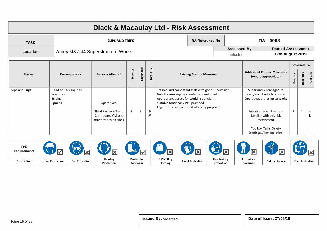
Page 16 of 28 Date of Issue: 27/08/18 Issued By:
Diack & Macaulay Ltd - Risk Assessment
TASK: SLIPS AND TRIPS RA Reference No RA - 0068
Location: Amey M8 Jct4 Superstructure Works Assessed By: Date of Assessment
19th August 2019
Hazard Consequences Persons Affected
Seve
rity
Like
liho
od
Tota
l Ris
k
Existing Control Measures Additional Control Measures
(where appropriate)
Residual Risk
Seve
rity
Like
liho
od
Tota
l Ris
k
Slips and Trips Head or Back Injuries Fractures Strains Sprains Operatives.
Third Parties (Client, Contractor, Visitors, other trades on site )
3 3
9 M
Trained and competent staff with good supervision. Good housekeeping standards maintained. Appropriate access for working at height. Suitable footwear / PPE provided Edge protection provided where appropriate
Supervisor / Manager to carry out checks to ensure
Operatives are using controls.
Ensure all operatives are familiar with this risk
assessment
Toolbox Talks, Safety Briefings, Alert Bulletins.
2 2
4 L
PPE Requirements
Description Head Protection Eye Protection Hearing
Protection Protective Footwear
Hi Visibility Clothing
Hand Protection Respiratory Protection
Protective Coveralls
Safety Harness Face Protection
redacted 11(2)
redacted 11(2)

Page 17 of 28 Date of Issue: 27/08/18 Issued
Diack & Macaulay Ltd - Risk Assessment
TASK: SPILLAGES RA Reference No RA - 0069
Location: Amey M8 Jct4 Superstructure Works Assessed By: Date of Assessment
19th August 2019
Hazard Consequences Persons Affected
Seve
rity
Like
liho
od
Tota
l Ris
k
Existing Control Measures Additional Control Measures
(where appropriate)
Residual Risk
Seve
rity
Like
liho
od
Tota
l Ris
k
Slips, trips, Contamination of water courses, drains, etc Surface damage
Injuries Operatives.
Third Parties (Client, Contractor, Visitors, other trades on site )
3 3
12 M
Ground under work area to be protected by sheeting or bundling Minimum amount of paints, oils or other substances to be at work site Additional cloths and absorbent materials to be available to clean spillages All waste to be secured in containers and returned to workshop for disposal
Supervisor / Manager to carry out checks to ensure
Operatives are using controls.
Ensure all operatives are familiar with this risk
assessment
Toolbox Talks, Safety Briefings, Alert Bulletins.
2 2
4 L
PPE Requirements
Description Head Protection Eye Protection Hearing
Protection Protective Footwear
Hi Visibility Clothing
Hand Protection Respiratory Protection
Protective Coveralls
Safety Harness Face Protection
redacted 11(2)
redacted 11(2)
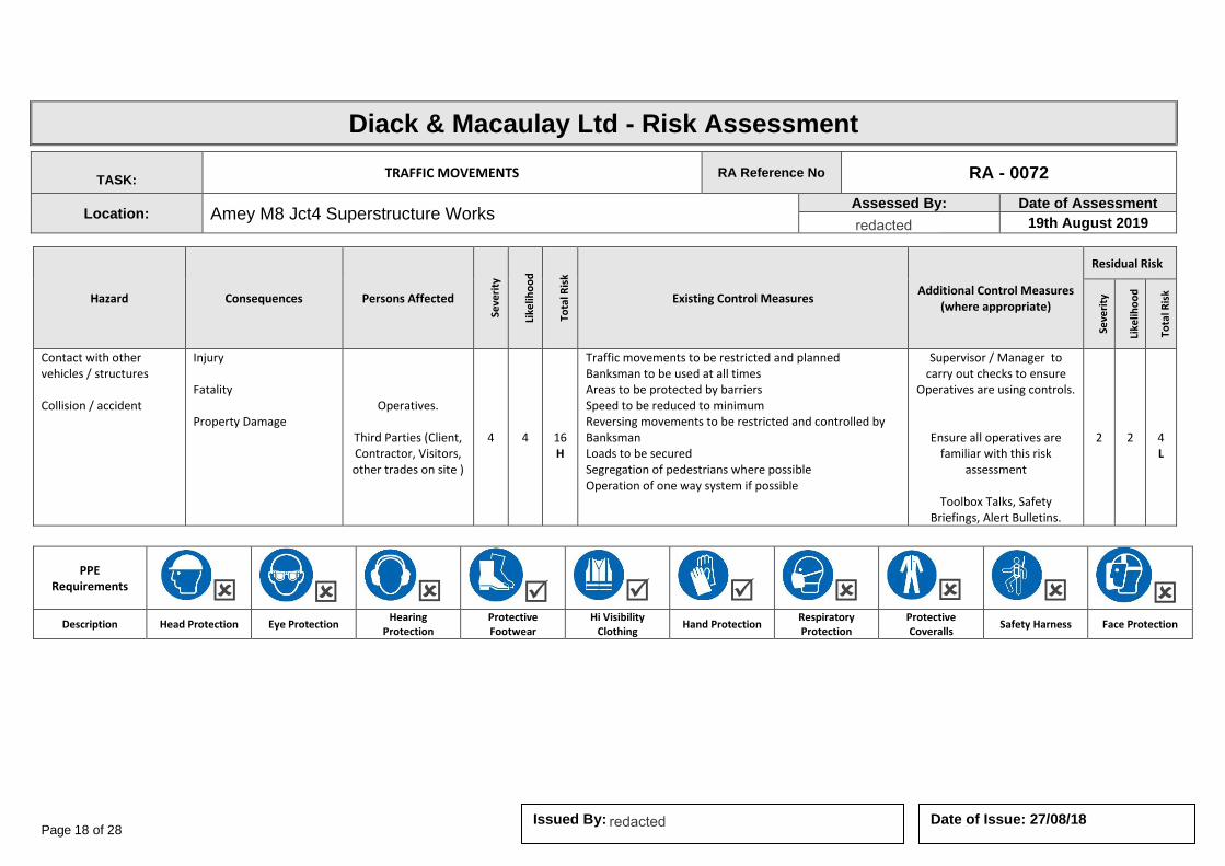
Page 18 of 28 Date of Issue: 27/08/18 Issued By:
Diack & Macaulay Ltd - Risk Assessment
TASK: TRAFFIC MOVEMENTS RA Reference No RA - 0072
Location: Amey M8 Jct4 Superstructure Works Assessed By: Date of Assessment
19th August 2019
Hazard Consequences Persons Affected
Seve
rity
Like
liho
od
Tota
l Ris
k
Existing Control Measures Additional Control Measures
(where appropriate)
Residual Risk
Seve
rity
Like
liho
od
Tota
l Ris
k
Contact with other vehicles / structures Collision / accident
Injury Fatality Property Damage
Operatives.
Third Parties (Client, Contractor, Visitors, other trades on site )
4 4
16 H
Traffic movements to be restricted and planned Banksman to be used at all times Areas to be protected by barriers Speed to be reduced to minimum Reversing movements to be restricted and controlled by Banksman Loads to be secured Segregation of pedestrians where possible Operation of one way system if possible
Supervisor / Manager to carry out checks to ensure
Operatives are using controls.
Ensure all operatives are familiar with this risk
assessment
Toolbox Talks, Safety Briefings, Alert Bulletins.
2 2
4 L
PPE Requirements
Description Head Protection Eye Protection Hearing
Protection Protective Footwear
Hi Visibility Clothing
Hand Protection Respiratory Protection
Protective Coveralls
Safety Harness Face Protection
redacted 11(2)
redacted 11(2)

Page 19 of 28 Date of Issue: 27/08/18 Issued By:
Diack & Macaulay Ltd - Risk Assessment
TASK: USE OF COMPRESSOR RA Reference No RA - 0078
Location: Amey M8 Jct4 Superstructure Works Assessed By: Date of Assessment
19th August 2019
Hazard Consequences Persons Affected
Seve
rity
Like
liho
od
Tota
l Ris
k
Existing Control Measures Additional Control Measures
(where appropriate)
Residual Risk
Seve
rity
Like
liho
od
Tota
l Ris
k
Noise and Vibration Dust/Particles Pressurised hose Exhaust fumes Movement of unit Contact with buried services
Hearing Damage Injury to operator Hearing damage
Electric shock
Operatives.
Third Parties (Client, Contractor, Visitors, other trades on site )
4 4
16 H
Only trained operatives to use equipment See assessment re buried services Hoses and equipment to be checked prior to use Unit to be braked and wheels chocked Restrict exposure to noise and vibration ensure good ventilation All electrical equipment to be PAT tested in accordance with current legislation Do not use compressed air to blow down clothing/body. Use of PPE
Supervisor / Manager to carry out checks to ensure
Operatives are using controls.
Ensure all operatives are familiar with this risk
assessment
Toolbox Talks, Safety Briefings, Alert Bulletins.
2 2
4 L
PPE Requirements
Description Head Protection Eye Protection Hearing
Protection Protective Footwear
Hi Visibility Clothing
Hand Protection Respiratory Protection
Protective Coveralls
Safety Harness Face Protection
redacted 11(2)
redacted 11(2)

Page 20 of 28 Date of Issue: 27/08/18 Issued By:
Diack & Macaulay Ltd - Risk Assessment
TASK: USE OF CRANES AND EXCAVATORS RA Reference No RA - 0079
Location: Amey M8 Jct4 Superstructure Works Assessed By: Date of Assessment
19th August 2019
Hazard Consequences Persons Affected
Seve
rity
Like
liho
od
Tota
l Ris
k
Existing Control Measures Additional Control Measures
(where appropriate)
Residual Risk
Seve
rity
Like
liho
od
Tota
l Ris
k
Overturning of plant Plant operations, contact with moving machinery Trapping Falling materials / unintentional collapse Noise, dust, debris O/head and underground services
Property damage Major Injury
Operatives.
Third Parties (Client, Contractor, Visitors, other trades on site )
3 3
9 M
Plant and operators certification to be checked Lifting operations to be planned in accordance with LOLER 98 Suitable area to be prepared for lifting activities Protection provided for underground / o/head services Banksman to be used at all times and adequate communication established All operatives and others to be withdrawn from the area to a safe location Suitable PPE to be worn
Supervisor / Manager to carry out checks to ensure Operatives are using controls.
Ensure all operatives are familiar with this risk assessment
Toolbox Talks, Safety Briefings, Alert Bulletins.
2 2
4 L
PPE Requirements
Description Head Protection Eye Protection Hearing
Protection Protective Footwear
Hi Visibility Clothing
Hand Protection Respiratory Protection
Protective Coveralls
Safety Harness Face Protection
redacted 11(2)
redacted 11(2)

Page 21 of 28 Date of Issue: 27/08/18 Issued By:
Diack & Macaulay Ltd - Risk Assessment
TASK: USE OF DRILLS RA Reference No RA - 0080
Location: Amey M8 Jct4 Superstructure Works Assessed By: Date of Assessment
19th August 2019
Hazard Consequences Persons Affected
Seve
rity
Like
liho
od
Tota
l Ris
k
Existing Control Measures Additional Control Measures
(where appropriate)
Residual Risk
Seve
rity
Like
liho
od
Tota
l Ris
k
Contact with moving parts Electric shock Noise / Vibration Unpredictable movement
Hearing damage Injury Cuts & bruises
Operatives.
Third Parties (Client, Contractor, Visitors, other trades on site )
3 3
9 M
Only tools in good condition should be used and inspected prior to use Loose clothing to be avoided Suitable P.P.E. to be worn Defective tools and equipment to be withdrawn from service Swarf to be removed from machine on completion of task Appropriate guarding to be in place during drilling operation Work piece to be secured prior to operation
Supervisor / Manager to carry out checks to ensure
Operatives are using controls.
Ensure all operatives are familiar with this risk
assessment
Toolbox Talks, Safety Briefings, Alert Bulletins.
2 2
4 L
PPE Requirements
Description Head Protection Eye Protection Hearing
Protection Protective Footwear
Hi Visibility Clothing
Hand Protection Respiratory Protection
Protective Coveralls
Safety Harness Face Protection
redacted 11(2)
redacted 11(2)
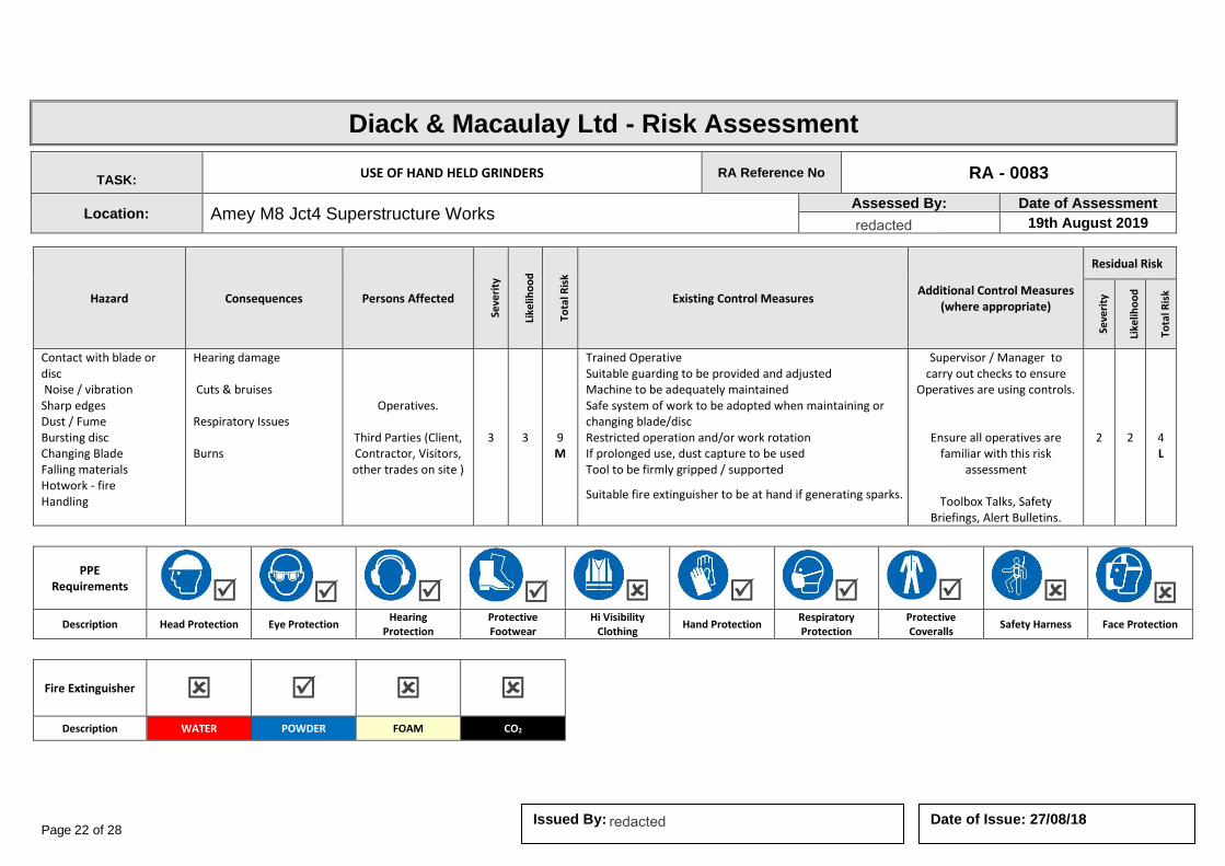
Page 22 of 28 Date of Issue: 27/08/18 Issued By:
Diack & Macaulay Ltd - Risk Assessment
TASK: USE OF HAND HELD GRINDERS RA Reference No RA - 0083
Location: Amey M8 Jct4 Superstructure Works Assessed By: Date of Assessment
19th August 2019
Hazard Consequences Persons Affected
Seve
rity
Like
liho
od
Tota
l Ris
k
Existing Control Measures Additional Control Measures
(where appropriate)
Residual Risk
Seve
rity
Like
liho
od
Tota
l Ris
k
Contact with blade or disc Noise / vibration Sharp edges Dust / Fume Bursting disc Changing Blade Falling materials Hotwork - fire Handling
Hearing damage Cuts & bruises Respiratory Issues Burns
Operatives.
Third Parties (Client, Contractor, Visitors, other trades on site )
3 3
9 M
Trained Operative Suitable guarding to be provided and adjusted Machine to be adequately maintained Safe system of work to be adopted when maintaining or changing blade/disc Restricted operation and/or work rotation If prolonged use, dust capture to be used Tool to be firmly gripped / supported
Suitable fire extinguisher to be at hand if generating sparks.
Supervisor / Manager to carry out checks to ensure
Operatives are using controls.
Ensure all operatives are familiar with this risk
assessment
Toolbox Talks, Safety Briefings, Alert Bulletins.
2 2
4 L
PPE Requirements
Description Head Protection Eye Protection Hearing
Protection Protective Footwear
Hi Visibility Clothing
Hand Protection Respiratory Protection
Protective Coveralls
Safety Harness Face Protection
Fire Extinguisher
Description WATER POWDER FOAM CO2
redacted 11(2)
redacted 11(2)
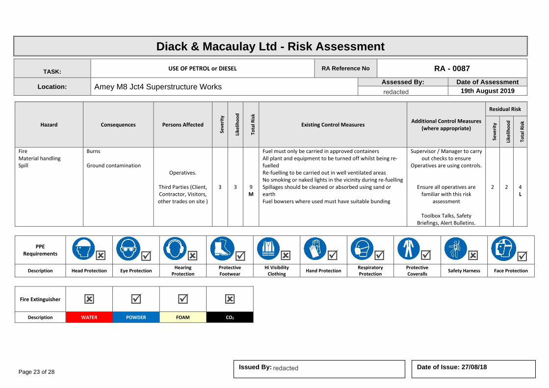
Page 23 of 28 Date of Issue: 27/08/18 Issued By:
Diack & Macaulay Ltd - Risk Assessment
TASK: USE OF PETROL or DIESEL RA Reference No RA - 0087
Location: Amey M8 Jct4 Superstructure Works Assessed By: Date of Assessment
19th August 2019
Hazard Consequences Persons Affected
Seve
rity
Like
liho
od
Tota
l Ris
k
Existing Control Measures Additional Control Measures
(where appropriate)
Residual Risk
Seve
rity
Like
liho
od
Tota
l Ris
k
Fire Material handling Spill
Burns Ground contamination
Operatives.
Third Parties (Client, Contractor, Visitors, other trades on site )
3 3
9 M
Fuel must only be carried in approved containers All plant and equipment to be turned off whilst being re-fuelled Re-fuelling to be carried out in well ventilated areas No smoking or naked lights in the vicinity during re-fuelling Spillages should be cleaned or absorbed using sand or earth Fuel bowsers where used must have suitable bunding
Supervisor / Manager to carry out checks to ensure
Operatives are using controls.
Ensure all operatives are familiar with this risk
assessment
Toolbox Talks, Safety Briefings, Alert Bulletins.
2 2
4 L
PPE Requirements
Description Head Protection Eye Protection Hearing
Protection Protective Footwear
Hi Visibility Clothing
Hand Protection Respiratory Protection
Protective Coveralls
Safety Harness Face Protection
Fire Extinguisher
Description WATER POWDER FOAM CO2
redacted 11(2)
redacted 11(2)
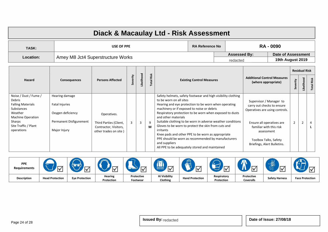
Page 24 of 28 Date of Issue: 27/08/18 Issued By:
Diack & Macaulay Ltd - Risk Assessment
TASK: USE OF PPE RA Reference No RA - 0090
Location: Amey M8 Jct4 Superstructure Works Assessed By: Date of Assessment
19th August 2019
Hazard Consequences Persons Affected
Seve
rity
Like
liho
od
Tota
l Ris
k
Existing Control Measures Additional Control Measures
(where appropriate)
Residual Risk
Seve
rity
Like
liho
od
Tota
l Ris
k
Noise / Dust / Fume / Debris Falling Materials Substances Weather Machine Operation Sharps Site Traffic / Plant operations
Hearing damage Fatal Injuries Oxygen deficiency Permanent Disfigurement Major Injury
Operatives.
Third Parties (Client, Contractor, Visitors, other trades on site )
3 3
9 M
Safety helmets, safety footwear and high visibility clothing to be worn on all sites Hearing and eye protection to be worn when operating machinery or if exposed to noise or debris Respiratory protection to be worn when exposed to dusts and other materials Suitable clothing to be worn in adverse weather conditions Gloves to be worn to protect the skin from cuts and irritants Knee pads and other PPE to be worn as appropriate PPE should be worn as recommended by manufacturers and suppliers All PPE to be adequately stored and maintained
Supervisor / Manager to carry out checks to ensure
Operatives are using controls.
Ensure all operatives are familiar with this risk
assessment
Toolbox Talks, Safety Briefings, Alert Bulletins.
2 2
4 L
PPE Requirements
Description Head Protection Eye Protection Hearing
Protection Protective Footwear
Hi Visibility Clothing
Hand Protection Respiratory Protection
Protective Coveralls
Safety Harness Face Protection
redacted 11(2)
redacted 11(2)

Page 25 of 28 Date of Issue: 27/08/18 Issued By:
Diack & Macaulay Ltd - Risk Assessment
TASK: WORK NEAR ROADWAYS RA Reference No RA - 0101
Location: Amey M8 Jct4 Superstructure Works Assessed By: Date of Assessment
19th August 2019
Hazard Consequences Persons Affected
Seve
rity
Like
liho
od
Tota
l Ris
k
Existing Control Measures Additional Control Measures
(where appropriate)
Residual Risk
Seve
rity
Like
liho
od
Tota
l Ris
k
Road Traffic Collision Major Injury Fatality
Operatives.
Third Parties (Client, Contractor, Visitors, other trades on site )
4 4
16 H
Where appropriate suitable traffic warning signs and cones / barriers to be erected Vehicles on site to display flashing amber lights All personnel to wear an appropriate level of Hi-visibility clothing If in doubt regarding roadworks consult highways authority or police Consult code of practice - Safety at street works and roadworks
Supervisor / Manager to carry out checks to ensure
Operatives are using controls.
Ensure all operatives are familiar with this risk
assessment
Toolbox Talks, Safety Briefings, Alert Bulletins.
2 2
4 L
PPE Requirements
Description Head Protection Eye Protection Hearing
Protection Protective Footwear
Hi Visibility Clothing
Hand Protection Respiratory Protection
Protective Coveralls
Safety Harness Face Protection
redacted 11(2)
redacted 11(2)

Page 26 of 28 Date of Issue: 27/08/18 Issued By:
Diack & Macaulay Ltd - Risk Assessment
TASK: WORK WITH HAZARDOUS SUBSTANCES RA Reference No RA - 0103
Location: Amey M8 Jct4 Superstructure Works Assessed By: Date of Assessment
19th August 2019
Hazard Consequences Persons Affected
Seve
rity
Like
liho
od
Tota
l Ris
k
Existing Control Measures Additional Control Measures
(where appropriate)
Residual Risk
Seve
rity
Like
liho
od
Tota
l Ris
k
Fumes Irritants Serious health hazards
Chemical Burns Respiratory Issues
Operatives.
Third Parties (Client, Contractor, Visitors, other trades on site )
4 4
16 H
Safer / alternative substances to be used whenever practical. Coshh assessments undertaken. Operatives trained in the use and aware of the hazards. Material safety data sheet available. Containers identified and labelled. Adequate ventilation provided. Suitable barriers or other controls to restrict access to work area. Spillage / waste to be disposed of in accordance with the manufacturer's instructions.
Supervisor / Manager to carry out checks to ensure
Operatives are using controls.
Ensure all operatives are familiar with this risk
assessment
Toolbox Talks, Safety Briefings, Alert Bulletins.
2 2
4 L
PPE Requirements
Description Head Protection Eye Protection Hearing
Protection Protective Footwear
Hi Visibility Clothing
Hand Protection Respiratory Protection
Protective Coveralls
Safety Harness Face Protection
redacted 11(2)
redacted 11(2)
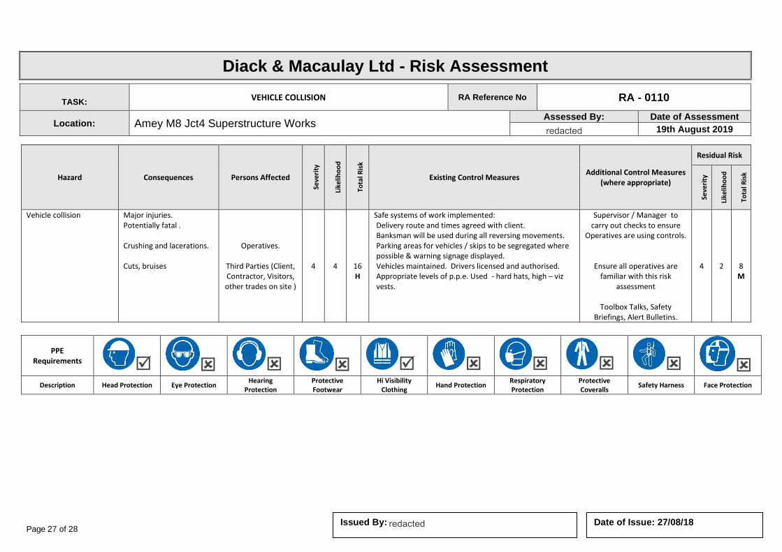
Page 27 of 28 Date of Issue: 27/08/18 Issued By:
Diack & Macaulay Ltd - Risk Assessment
TASK: VEHICLE COLLISION RA Reference No RA - 0110
Location: Amey M8 Jct4 Superstructure Works Assessed By: Date of Assessment
19th August 2019
Hazard Consequences Persons Affected
Seve
rity
Like
liho
od
Tota
l Ris
k
Existing Control Measures Additional Control Measures
(where appropriate)
Residual Risk
Seve
rity
Like
liho
od
Tota
l Ris
k
Vehicle collision Major injuries. Potentially fatal . Crushing and lacerations. Cuts, bruises
Operatives.
Third Parties (Client, Contractor, Visitors, other trades on site )
4 4
16 H
Safe systems of work implemented: Delivery route and times agreed with client. Banksman will be used during all reversing movements. Parking areas for vehicles / skips to be segregated where possible & warning signage displayed. Vehicles maintained. Drivers licensed and authorised. Appropriate levels of p.p.e. Used - hard hats, high – viz vests.
Supervisor / Manager to carry out checks to ensure
Operatives are using controls.
Ensure all operatives are familiar with this risk
assessment
Toolbox Talks, Safety Briefings, Alert Bulletins.
4 2
8 M
PPE Requirements
Description Head Protection Eye Protection Hearing
Protection Protective Footwear
Hi Visibility Clothing
Hand Protection Respiratory Protection
Protective Coveralls
Safety Harness Face Protection
redacted 11(2)
redacted 11(2)

Page 28 of 28 Date of Issue: 27/08/18 Issued By:
Diack & Macaulay Ltd - Risk Assessment
TASK: REFUELLING OPERATIONS RA Reference No RA - 0113
Location: Amey M8 Jct4 Superstructure Works Assessed By: Date of Assessment
19th August 2019
Hazard Consequences Persons Affected
Seve
rity
Like
liho
od
Tota
l Ris
k
Existing Control Measures Additional Control Measures
(where appropriate)
Residual Risk
Seve
rity
Like
liho
od
Tota
l Ris
k
Fuel spillage and ignition Contact with substances Spillage - Environmental
Fire and/or Burns Occupational dermatitis Environmental incident.
Operatives.
Third Parties (Client, Contractor, Visitors, other trades on site )
4 4
16 H
Suitable fire extinguisher at hand – Powder or Foam – NOT water. PPE to be worn – chemical resistant gloves, light eye protection. Spill kit to be available. Funnel to provided and used. Any container used for transporting fuel is fit for purpose, has a sealed lid, does not leak and is properly labelled. Provision of secure safe storage facility on appliance and fuelling aids No refuelling near to sources of ignition Fuel only in well ventilated outdoor areas Shut off equipment and allow to cool before refuelling Release filler cap slowly to relieve fuel tank pressure Do not overfill beyond ‘max’ level Wipe off any spilled fuel, tighten fuel cap and check for leaks after refuelling Change clothes immediately if fuel is spilled on clothes Ensure contaminated rags etc are disposed of safely and not stored near ignition sources.
Supervisor / Manager to carry out checks to ensure Operatives
are using controls.
Ensure all operatives are familiar with this risk assessment
Toolbox Talks, Safety Briefings,
Alert Bulletins.
3 3
9 M
PPE Requirements
Description Head Protection Eye Protection Hearing
Protection Protective Footwear
Hi Visibility Clothing
Hand Protection Respiratory Protection
Protective Coveralls
Safety Harness Face Protection
Fire Extinguisher
Description WATER POWDER FOAM CO2
redacted 11(2)
redacted 11(2)
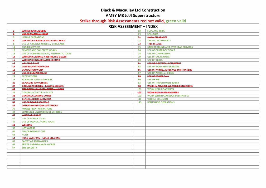
Diack & Macaulay Ltd Construction AMEY M8 Jct4 Superstructure
Strike through Risk Assessments red not valid, green valid RISK ASSESSMENT – INDEX
1 WORK FROM LADDERS 68 SLIPS AND TRIPS
2 USE OF MATERIAL HOIST 69 SPILLAGES
3 LIFTING OPERATIONS 71 SNOW CLEARANCE
4 USE AND STORAGE OF PALLETISED BRICK 72 TRAFFIC MOVEMENTS
8 USE OF ABRASIVE WHEELS / STIHL SAWS 73 TREE FELLING
11 BURIED SERVICES 75 UNDERGROUND AND OVERHEAD SERVICES
12 CEMENT AND CONCRETE WORKS 76 USE OF CARTRIDGE TOOLS
13 USE OF COMPRESSED AIR / PNEUMATIC TOOLS 78 USE OF COMPRESSOR
14 WORK IN CONFINED / RESTRICTED SPACES 79 USE OF EXCAVATORS
15 WORK IN CONTAMINATED GROUND 80 USE OF DRILLS
16 WELDING FUME 81 USE OF ELECTRICAL EQUIPMENT
17 DEEP EXCAVATION WORK 83 USE OF HAND HELD GRINDERS
18 DEMOLITION WORK 86 USE OF PAINTS, ADHESIVES and THINNERS
19 USE OF DUMPER TRUCK 87 USE OF PETROL or DIESEL
24 EXCAVATIONS 89 USE OF POWER SAW
25 EXPOSURE TO LIVE SERVICES 90 USE OF PPE
26 EXPOSURE TO VIOLENCE 93 USE OF TAR/BITUMEN BOILER
27 GROUND WORKERS – FALLING OBJECTS 98 WORK IN ADVERSE WEATHER CONDITIONS
28 FIRE RISK DURING DEMOLITION WORKS 101 WORK NEAR ROADWAYS
31 GENERAL ACTIVITIES – DUSTS 102 WORK NEAR WATERCOURSES
32 GENERAL CLEANING DUTIES 103 WORK WITH HAZARDOUS SUBSTANCES
33 GENERAL OFFICE ACTIVITIES 110 VEHICLE COLLISION
36 USE OF TOWER SCAFFOLD 113 REFUELLING OPERATIONS
37 OPERATION OF FORK LIFT TRUCKS
39 MOBILE PLANT OPERATIONS
42 LOADING & UNLOADING OF VEHICLES
43 WORK AT HEIGHT
44 USE OF POWER TOOLS
45 USE OF MANUAL/HAND TOOLS
51 WELDING
52 HOT WORKS
61 MINOR DEMOLITIONS
63 NOISE
64 ROAD SWEEPING – GULLY CLEARING
65 SAFETY AT ROADWORKS
66 SEWER AND DRAINAGE WORKS
67 SITE SECURITY

Page 2 of 35 Date of Issue: 27/08/18 Issued By
Risk Assessment Matrix
The aim is to reduce the risk by prevention or control measures, so far as is reasonably practicable.
Severity / Consequence Categories
Severity Description
Catastrophic Multiple fatalities (employees or third parties). Catastrophic environmental impact, resulting in irreversible / long term harm to the environment.
Significant Single fatality (employee or third party), loss of limbs, permanent severe disablement. Severe environmental incident resulting in significant impact requiring management by external authorities and / or high level of resources for response and remedy. Reversible / medium term harm to the environment.
Moderate Major injury / ill – health effect such as breaking a major bone or temporary disablement requiring hospital / casualty treatment and resulting in time off work. Moderate environmental impact requiring management response to aid recovery and resulting in reversible / short term harm to the environment.
Low Minor injury / ill health effect requiring medical treatment beyond first aid. Restricted duties may be possible. Low environmental impact, not requiring management response.
Negligible First aid case, no lost time. Negligible safety impact. Negligible environmental impact not requiring management response.
Severity / Consequences
1 2 3 4 5
Negligible Low Moderate Significant Catastrophic
LIK
LIEH
OO
D
(Ch
ance
of
Ris
k)
5 Certain >90% 5 (L) 10 (M) 15 (H) 20 (H) 25 (H)
H High – Stop operations and rectify immediately. Senior management decision required to accept or reject risk
4 Likely >50% <90% 4 (L) 8 (M) 12 (M) 16(H) 20 (H)
M Medium - Maintain current controls. Management to review and determine if further controls are required.
3 Possible >10% <50% 3 (L) 6 (L) 9 (M) 12 (M) 15 (H)
L Low – No further controls are required.
2 Remote >1% <10% 2 (L) 4 (L) 6 (L) 8 (M) 10 (M)
1 Unlikely <1% 1 (L) 2 (L) 3 (L) 4 (M) 5 (M)
redacted 11(2)

Page 3 of 35 Date of Issue: 27/08/18 Issued By:
Diack & Macaulay Ltd - Risk Assessment
TASK: LIFTING OPERATIONS RA Reference No RA - 0003
Location: Amey M8 Jct4 Superstructure Works Assessed By: Date of Assessment
19th August 2019
Hazard Consequences Persons Affected
Seve
rity
Like
liho
od
Tota
l Ris
k
Existing Control Measures Additional Control Measures
(where appropriate)
Residual Risk
Seve
rity
Like
liho
od
Tota
l Ris
k
Defective / inadequate
equipment
Incorrect positioning
Working within lane closure
Unsuitable base
Overhead cables and
other obstructions
Insecure load
Swinging load
Weather conditions
Injuries to operative,
other trades, members of the public and or
visitors including minor to fatal.
Damage to plant and or premises
Operatives.
Third Parties (Client, Contractor, Visitors, other trades on site)
4 4
16 H
Suitable certification to be provided and necessary inspections carried out
Safe working area to be provided for operation of equipment
Trained operator and banksman to be used
Hi-visibility clothing to be worn by banksman as well as other P.P.E.
Ensure loads are not excessive and that they are properly secured Ensure correct and certified lifting equipment in use
Stop work in adverse weather conditions Lifting plan to be created.
Other operatives to be kept clear of operation
Supervisor / Manager to carry out checks to ensure
Operatives are using controls.
Exclusion zone erected and enforced during lifting
operation
Ensure all operatives are familiar with this risk
assessment
Edge restraints to be used on high sided vehicles
No lifting over live
carriageway
Toolbox Talks, Safety Briefings, Alert Bulletins.
4 1
4 L
PPE Requirements
Description Head Protection Eye Protection Hearing
Protection Protective Footwear
Hi Visibility Clothing
Hand Protection Respiratory Protection
Protective Coveralls
Safety Harness Face Protection
redacted 11(2)
redacted 11(2)
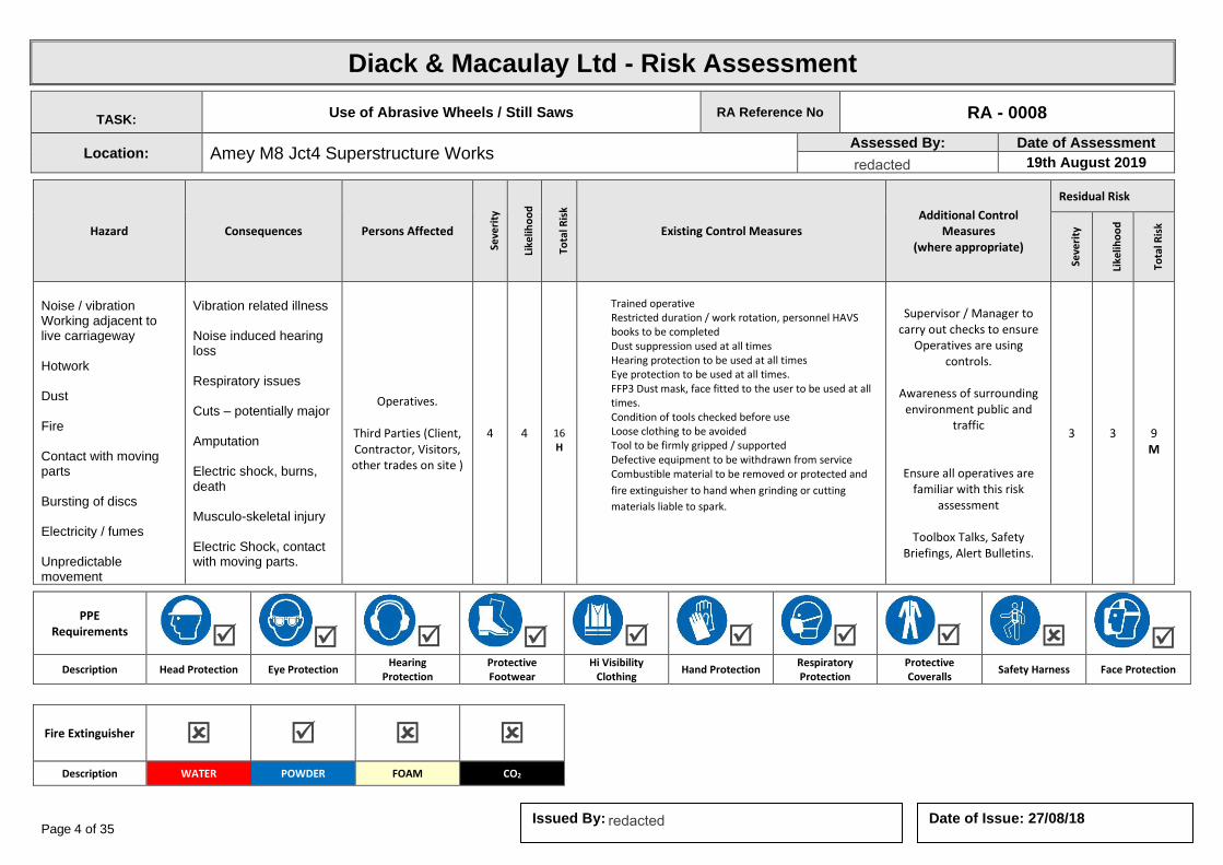
Page 4 of 35 Date of Issue: 27/08/18 Issued By:
Diack & Macaulay Ltd - Risk Assessment
TASK: Use of Abrasive Wheels / Still Saws RA Reference No RA - 0008
Location: Amey M8 Jct4 Superstructure Works Assessed By: Date of Assessment
19th August 2019
Hazard Consequences Persons Affected
Seve
rity
Like
liho
od
Tota
l Ris
k
Existing Control Measures Additional Control
Measures (where appropriate)
Residual Risk
Seve
rity
Like
liho
od
Tota
l Ris
k
Noise / vibration Working adjacent to live carriageway Hotwork Dust Fire Contact with moving parts Bursting of discs Electricity / fumes Unpredictable movement
Vibration related illness Noise induced hearing loss Respiratory issues Cuts – potentially major Amputation Electric shock, burns, death Musculo-skeletal injury Electric Shock, contact with moving parts.
Operatives.
Third Parties (Client, Contractor, Visitors, other trades on site )
4 4
16 H
Trained operative Restricted duration / work rotation, personnel HAVS books to be completed Dust suppression used at all times Hearing protection to be used at all times Eye protection to be used at all times. FFP3 Dust mask, face fitted to the user to be used at all times. Condition of tools checked before use Loose clothing to be avoided Tool to be firmly gripped / supported Defective equipment to be withdrawn from service Combustible material to be removed or protected and
fire extinguisher to hand when grinding or cutting
materials liable to spark.
Supervisor / Manager to carry out checks to ensure
Operatives are using controls.
Awareness of surrounding
environment public and traffic
Ensure all operatives are familiar with this risk
assessment
Toolbox Talks, Safety Briefings, Alert Bulletins.
3 3
9 M
PPE Requirements
Description Head Protection Eye Protection Hearing
Protection Protective Footwear
Hi Visibility Clothing
Hand Protection Respiratory Protection
Protective Coveralls
Safety Harness Face Protection
Fire Extinguisher
Description WATER POWDER FOAM CO2
redacted 11(2)
redacted 11(2)
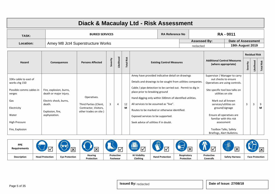
Page 5 of 35 Date of Issue: 27/08/18 Issued By:
Diack & Macaulay Ltd - Risk Assessment
TASK: BURIED SERVICES RA Reference No RA - 0011
Location: Amey M8 Jct4 Superstructure Works Assessed By: Date of Assessment
19th August 2019
Hazard Consequences Persons Affected
Seve
rity
Like
liho
od
Tota
l Ris
k
Existing Control Measures Additional Control Measures
(where appropriate)
Residual Risk
Seve
rity
Like
liho
od
Tota
l Ris
k
33Kv cable to east of works chg 150 Possible comms cables in verges Gas Electricity Water High Pressure Fire, Explosion
Fire, explosion, burns, death or major injury. Electric shock, burns, death. Explosion, fire, asphyxiation.
Operatives.
Third Parties (Client, Contractor, Visitors, other trades on site )
3 4
12 M
Amey have provided indicative detail on drawings
Details and drawings to be sought from utilities companies.
Cable / pipe detection to be carried out. Permit to dig in
place prior to breaking ground
Hand digging only within 500mm of identified utilities.
All services to be assumed as “live”.
Routes to be marked or otherwise identified.
Exposed services to be supported.
Seek advice of utilities if in doubt.
Supervisor / Manager to carry out checks to ensure
Operatives are using controls.
Site specific tool box talks on utilities on site
Mark out all known services/utilities on
ground/signage
Ensure all operatives are familiar with this risk
assessment
Toolbox Talks, Safety Briefings, Alert Bulletins.
3 3
9 M
PPE Requirements
Description Head Protection Eye Protection Hearing
Protection Protective Footwear
Hi Visibility Clothing
Hand Protection Respiratory Protection
Protective Coveralls
Safety Harness Face Protection
redacted 11(2)
redacted 11(2)

Page 6 of 35 Date of Issue: 27/08/18 Issued By:
Diack & Macaulay Ltd - Risk Assessment
TASK: CEMENT AND CONCRETE WORKS RA Reference No RA - 0012
Location: Amey M8 Jct4 Superstructure Works Assessed By: Date of Assessment
19th August 2019
Hazard Consequences Persons Affected
Seve
rity
Like
liho
od
Tota
l Ris
k
Existing Control Measures Additional Control Measures
(where appropriate)
Residual Risk
Seve
rity
Like
liho
od
Tota
l Ris
k
Disposal of waste concrete Dusts Irritants Materials handling Plant operation Noise Site Traffic Concrete spill
Burns, Muscular Skeletal Injuries, Broken Bones, Hearing Damage, Major Injuries Pollution to ground, contamination
Operatives.
Third Parties (Client, Contractor, Visitors, other trades on site )
3 4
12 M
Suitable PPE to be worn No eating or drinking on site
Avoid contact with wet cement
Avoid exposure to excessive dust from cement / aggregates
Beware of slip / trip hazards
Beware of plant activities
Designated working areas
Supervisor / Manager to carry out checks to ensure
Operatives are using controls.
Ensure all operatives are familiar with this risk
assessment
Toolbox Talks, Safety Briefings, Alert Bulletins.
2 3
6 L
PPE Requirements
Description Head Protection Eye Protection Hearing
Protection Protective Footwear
Hi Visibility Clothing
Hand Protection Respiratory Protection
Protective Coveralls
Safety Harness Face Protection
redacted 11(2)
redacted 11(2)
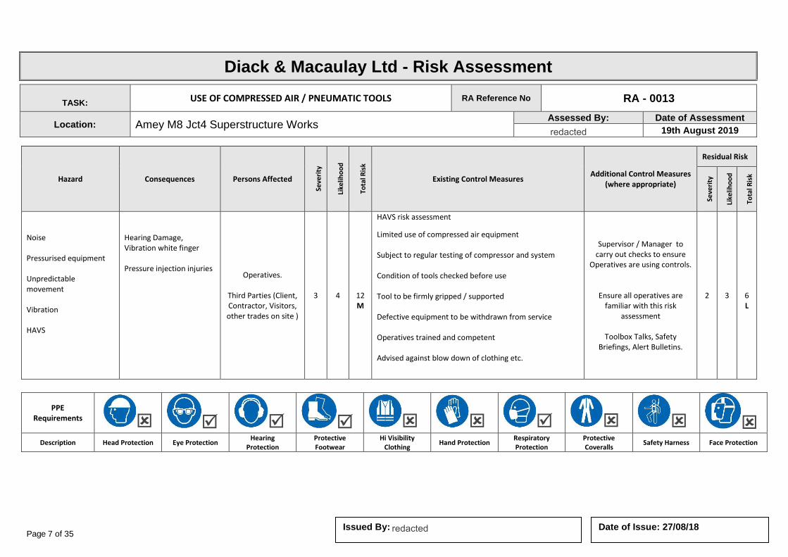
Page 7 of 35 Date of Issue: 27/08/18 Issued By:
Diack & Macaulay Ltd - Risk Assessment
TASK: USE OF COMPRESSED AIR / PNEUMATIC TOOLS RA Reference No RA - 0013
Location: Amey M8 Jct4 Superstructure Works Assessed By: Date of Assessment
19th August 2019
Hazard Consequences Persons Affected
Seve
rity
Like
liho
od
Tota
l Ris
k
Existing Control Measures Additional Control Measures
(where appropriate)
Residual Risk
Seve
rity
Like
liho
od
Tota
l Ris
k
Noise Pressurised equipment Unpredictable movement Vibration HAVS
Hearing Damage, Vibration white finger Pressure injection injuries Operatives.
Third Parties (Client, Contractor, Visitors, other trades on site )
3 4
12 M
HAVS risk assessment
Limited use of compressed air equipment Subject to regular testing of compressor and system Condition of tools checked before use Tool to be firmly gripped / supported Defective equipment to be withdrawn from service Operatives trained and competent Advised against blow down of clothing etc.
Supervisor / Manager to carry out checks to ensure
Operatives are using controls.
Ensure all operatives are familiar with this risk
assessment
Toolbox Talks, Safety Briefings, Alert Bulletins.
2 3
6 L
PPE Requirements
Description Head Protection Eye Protection Hearing
Protection Protective Footwear
Hi Visibility Clothing
Hand Protection Respiratory Protection
Protective Coveralls
Safety Harness Face Protection
redacted 11(2)
redacted 11(2)

Page 8 of 35 Date of Issue: 27/08/18 Issued By:
Diack & Macaulay Ltd - Risk Assessment
TASK: EXCAVATIONS RA Reference No RA – 0024
Location: Amey M8 Jct4 Superstructure Works Assessed By: Date of Assessment
19th August 2019
Hazard Consequences Persons Affected
Seve
rity
Like
liho
od
Tota
l Ris
k
Existing Control Measures Additional Control Measures
(where appropriate)
Residual Risk
Seve
rity
Like
liho
od
Tota
l Ris
k
Personnel or third party falling in to excavation. Adjacent traffic running on carriageway Site traffic Ground conditions Moving plant Fall of materials Flooding Noise
Contact with moving plant, fatality/ major injury Collapse of trench Struck by falling materials Hearing damage Fall into excavations
Operatives.
Third Parties (Client, Contractor, Visitors, other trades on site )
4 4
16 H
Site enclosed by suitable barriers, notices, etc Utilities checked by drawings and cable locating equipment used Plant operations carried out by suitably trained operatives and banksmen used Ground conditions checked and appropriate precautions taken to prevent collapse - trench boxes, shoring or sides battered back to suitable angle to prevent collapse. Material used for supporting excavation is sound and free from defects. No person is allowed to enter an excavation unless the sides are adequately supported or battered. Suitable access provided Operatives advised of need for good hygiene practices and to cover exposed skin Operatives to stand well clear of operating plant or machinery Where vehicles are used in close proximity to the excavation, vehicle stops should be erected at a safe distance from the edge of the excavation. Supervisor to undertake regular checks of excavations and record where necessary Means of emptying water to be provided if necessary. Emergency procedure established and communicated to the employees for use in the event of major incidents which can occur. All lifting equipment used in raising and lowering supports and equipment in excavations work should be inspected by a competent person.
Supervisor / Manager to carry out checks to ensure
Operatives are using controls.
Site inductions
Ensure all operatives are familiar with this risk
assessment
Toolbox Talks, Safety Briefings, Alert Bulletins.
3 3
9 M
PPE Requirements
Description Head Protection Eye Protection Hearing
Protection Protective Footwear
Hi Visibility Clothing
Hand Protection Respiratory Protection
Protective Coveralls
Safety Harness Face Protection
redacted 11(2)
redacted 11(2)

Page 9 of 35 Date of Issue: 27/08/18 Issued By:
Diack & Macaulay Ltd - Risk Assessment
TASK: EXPOSURE TO LIVE SERVICES RA Reference No RA – 0025
Location: Amey M8 Jct4 Superstructure Works Assessed By: Date of Assessment
19th August 2019
Hazard Consequences Persons Affected
Seve
rity
Like
liho
od
Tota
l Ris
k
Existing Control Measures Additional Control Measures
(where appropriate)
Residual Risk
Seve
rity
Like
liho
od
Tota
l Ris
k
Gas Electricity Water High pressure Fire, Explosion
Fatalities Electric shock Skin punctures Burns
Operatives.
Third Parties (Client, Contractor, Visitors, other trades on site )
4 4
16 H
Details and drawings to be sought from utilities companies. Cable / pipe detection to be carried out. Hand digging only within 500mm of identified utilities. All services to be assumed as “live”. Routes to be marked or otherwise identified. Exposed services to be supported and protected Seek advice of utilities if in doubt.
Supervisor / Manager to carry out checks to ensure
Operatives are using controls.
Ensure all operatives are familiar with this risk
assessment
Toolbox Talks, Safety Briefings, Alert Bulletins.
3 3
9 M
PPE Requirements
Description Head Protection Eye Protection Hearing
Protection Protective Footwear
Hi Visibility Clothing
Hand Protection Respiratory Protection
Protective Coveralls
Safety Harness Face Protection
redacted 11(2)
redacted 11(2)
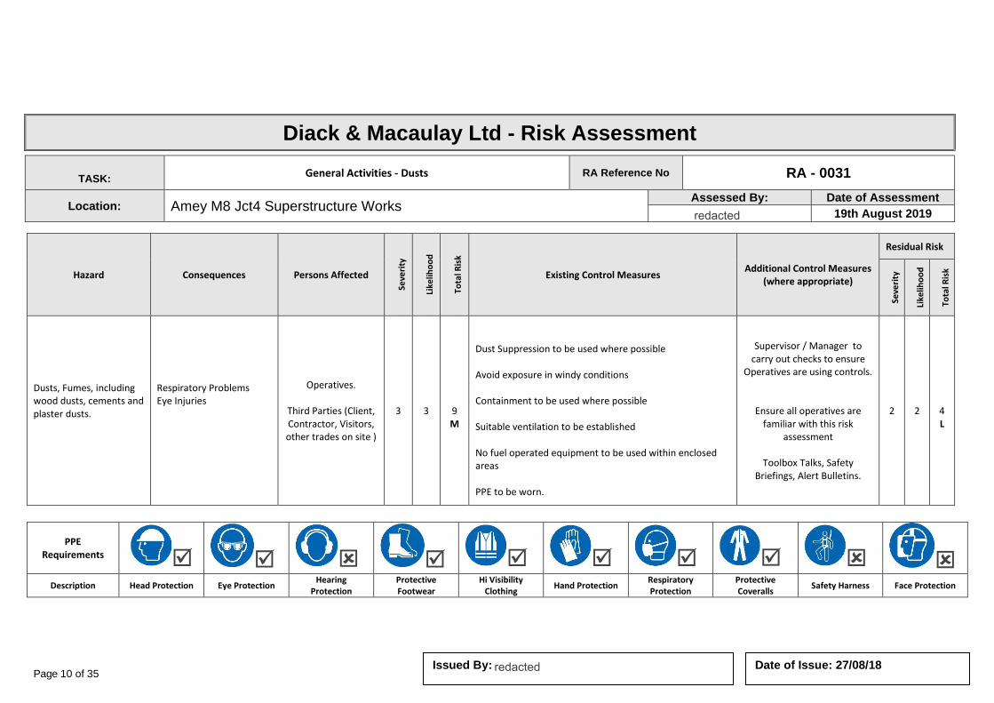
Page 10 of 35 Date of Issue: 27/08/18 Issued By:
Diack & Macaulay Ltd - Risk Assessment
TASK: General Activities - Dusts RA Reference No RA - 0031
Location: Amey M8 Jct4 Superstructure Works Assessed By: Date of Assessment
19th August 2019
Hazard Consequences Persons Affected
Seve
rity
Like
liho
od
Tota
l Ris
k
Existing Control Measures Additional Control Measures
(where appropriate)
Residual Risk
Seve
rity
Like
liho
od
Tota
l Ris
k
Dusts, Fumes, including wood dusts, cements and plaster dusts.
Respiratory Problems Eye Injuries
Operatives.
Third Parties (Client, Contractor, Visitors, other trades on site )
3 3
9 M
Dust Suppression to be used where possible Avoid exposure in windy conditions Containment to be used where possible Suitable ventilation to be established No fuel operated equipment to be used within enclosed areas PPE to be worn.
Supervisor / Manager to carry out checks to ensure
Operatives are using controls.
Ensure all operatives are familiar with this risk
assessment
Toolbox Talks, Safety Briefings, Alert Bulletins.
2 2
4 L
PPE Requirements
Description Head Protection Eye Protection Hearing
Protection Protective Footwear
Hi Visibility Clothing
Hand Protection Respiratory Protection
Protective Coveralls
Safety Harness Face Protection
redacted 11(2)
redacted 11(2)
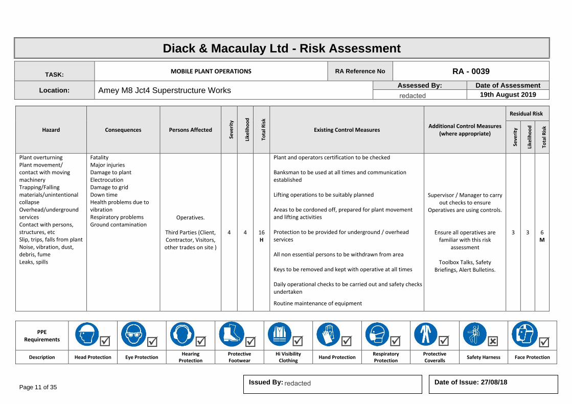
Page 11 of 35 Date of Issue: 27/08/18 Issued By:
Diack & Macaulay Ltd - Risk Assessment
TASK: MOBILE PLANT OPERATIONS RA Reference No RA - 0039
Location: Amey M8 Jct4 Superstructure Works Assessed By: Date of Assessment
19th August 2019
Hazard Consequences Persons Affected
Seve
rity
Like
liho
od
Tota
l Ris
k
Existing Control Measures Additional Control Measures
(where appropriate)
Residual Risk
Seve
rity
Like
liho
od
Tota
l Ris
k
Plant overturning Plant movement/ contact with moving machinery Trapping/Falling materials/unintentional collapse Overhead/underground services Contact with persons, structures, etc Slip, trips, falls from plant Noise, vibration, dust, debris, fume Leaks, spills
Fatality Major injuries Damage to plant Electrocution Damage to grid Down time Health problems due to vibration Respiratory problems Ground contamination
Operatives.
Third Parties (Client, Contractor, Visitors, other trades on site )
4 4
16 H
Plant and operators certification to be checked Banksman to be used at all times and communication established Lifting operations to be suitably planned Areas to be cordoned off, prepared for plant movement and lifting activities Protection to be provided for underground / overhead services All non essential persons to be withdrawn from area Keys to be removed and kept with operative at all times Daily operational checks to be carried out and safety checks undertaken
Routine maintenance of equipment
Supervisor / Manager to carry out checks to ensure
Operatives are using controls.
Ensure all operatives are familiar with this risk
assessment
Toolbox Talks, Safety Briefings, Alert Bulletins.
3 3
6 M
PPE Requirements
Description Head Protection Eye Protection Hearing
Protection Protective Footwear
Hi Visibility Clothing
Hand Protection Respiratory Protection
Protective Coveralls
Safety Harness Face Protection
redacted 11(2)
redacted 11(2)

Page 12 of 35 Date of Issue: 27/08/18 Issued By:
Diack & Macaulay Ltd - Risk Assessment
TASK: LOADING & UNLOADING OF VEHICLES RA Reference No RA - 0042
Location: Amey M8 Jct4 Superstructure Works Assessed By: Date of Assessment
19th August 2019
Hazard Consequences Persons Affected
Seve
rity
Like
liho
od
Tota
l Ris
k
Existing Control Measures Additional Control Measures
(where appropriate)
Residual Risk
Seve
rity
Like
liho
od
Tota
l Ris
k
Loading and Unloading of
vehicles. Contact with other vehicles / structures Collision / accident Unstable Loads Falls of Loads Use of Mechanical Lifting equipment Falls from vehicle. Manual Handling Injuries Operatives.
Third Parties (Client, Contractor, Visitors, other trades on site )
4 4
16 H
Traffic movements to be restricted and planned Banksman to be used at all times particularly if reversing Suitable area to be determined for loading / unloading Operations to be planned so that no persons are required to mount the rear load deck of a vehicle. Use to be made of mechanical aids (Tail Lift or Hiab facility) Stabilisers to be used when loading / unloading vehicles if fitted All persons must keep clear of swinging or suspended loads Lifting equipment and accessories must have current and appropriate documentation If unloading by hand, ensure weights are known and within the capability of staff, where possible, loads should be broken down into manageable sizes. Staff shall be trained in appropriate manual handling techniques.
Supervisor / Manager to carry out checks to ensure
Operatives are using controls.
Ensure all operatives are familiar with this risk
assessment
Toolbox Talks, Safety Briefings, Alert Bulletins.
3 3
6 M
PPE Requirements
Description Head Protection Eye Protection Hearing
Protection Protective Footwear
Hi Visibility Clothing
Hand Protection Respiratory Protection
Protective Coveralls
Safety Harness Face Protection
redacted 11(2)
redacted 11(2)
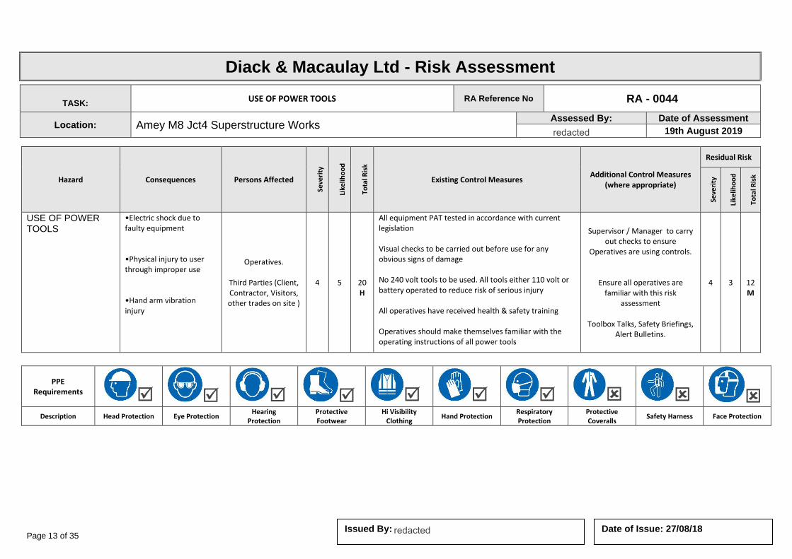
Page 13 of 35 Date of Issue: 27/08/18 Issued By:
Diack & Macaulay Ltd - Risk Assessment
TASK: USE OF POWER TOOLS RA Reference No RA - 0044
Location: Amey M8 Jct4 Superstructure Works Assessed By: Date of Assessment
19th August 2019
Hazard Consequences Persons Affected
Seve
rity
Like
liho
od
Tota
l Ris
k
Existing Control Measures Additional Control Measures
(where appropriate)
Residual Risk
Seve
rity
Like
liho
od
Tota
l Ris
k
USE OF POWER TOOLS
•Electric shock due to faulty equipment •Physical injury to user through improper use •Hand arm vibration injury
Operatives.
Third Parties (Client, Contractor, Visitors, other trades on site )
4 5
20 H
All equipment PAT tested in accordance with current legislation Visual checks to be carried out before use for any obvious signs of damage No 240 volt tools to be used. All tools either 110 volt or battery operated to reduce risk of serious injury All operatives have received health & safety training Operatives should make themselves familiar with the operating instructions of all power tools
Supervisor / Manager to carry out checks to ensure
Operatives are using controls.
Ensure all operatives are familiar with this risk
assessment
Toolbox Talks, Safety Briefings, Alert Bulletins.
4 3
12 M
PPE Requirements
Description Head Protection Eye Protection Hearing
Protection Protective Footwear
Hi Visibility Clothing
Hand Protection Respiratory Protection
Protective Coveralls
Safety Harness Face Protection
redacted 11(2)
redacted 11(2)
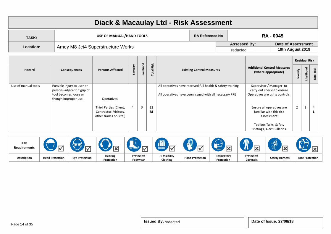
Page 14 of 35 Date of Issue: 27/08/18 Issued By:
Diack & Macaulay Ltd - Risk Assessment
TASK: USE OF MANUAL/HAND TOOLS RA Reference No RA - 0045
Location: Amey M8 Jct4 Superstructure Works Assessed By: Date of Assessment
19th August 2019
Hazard Consequences Persons Affected
Seve
rity
Like
liho
od
Tota
l Ris
k
Existing Control Measures Additional Control Measures
(where appropriate)
Residual Risk
Seve
rity
Like
liho
od
Tota
l Ris
k
Use of manual tools Possible injury to user or persons adjacent if grip of tool becomes loose or though improper use. Operatives.
Third Parties (Client, Contractor, Visitors, other trades on site )
4 3
12 M
All operatives have received full health & safety training All operatives have been issued with all necessary PPE
Supervisor / Manager to carry out checks to ensure
Operatives are using controls.
Ensure all operatives are familiar with this risk
assessment
Toolbox Talks, Safety Briefings, Alert Bulletins.
2 2
4 L
PPE Requirements
Description Head Protection Eye Protection Hearing
Protection Protective Footwear
Hi Visibility Clothing
Hand Protection Respiratory Protection
Protective Coveralls
Safety Harness Face Protection
redacted 11(2)
redacted 11(2)
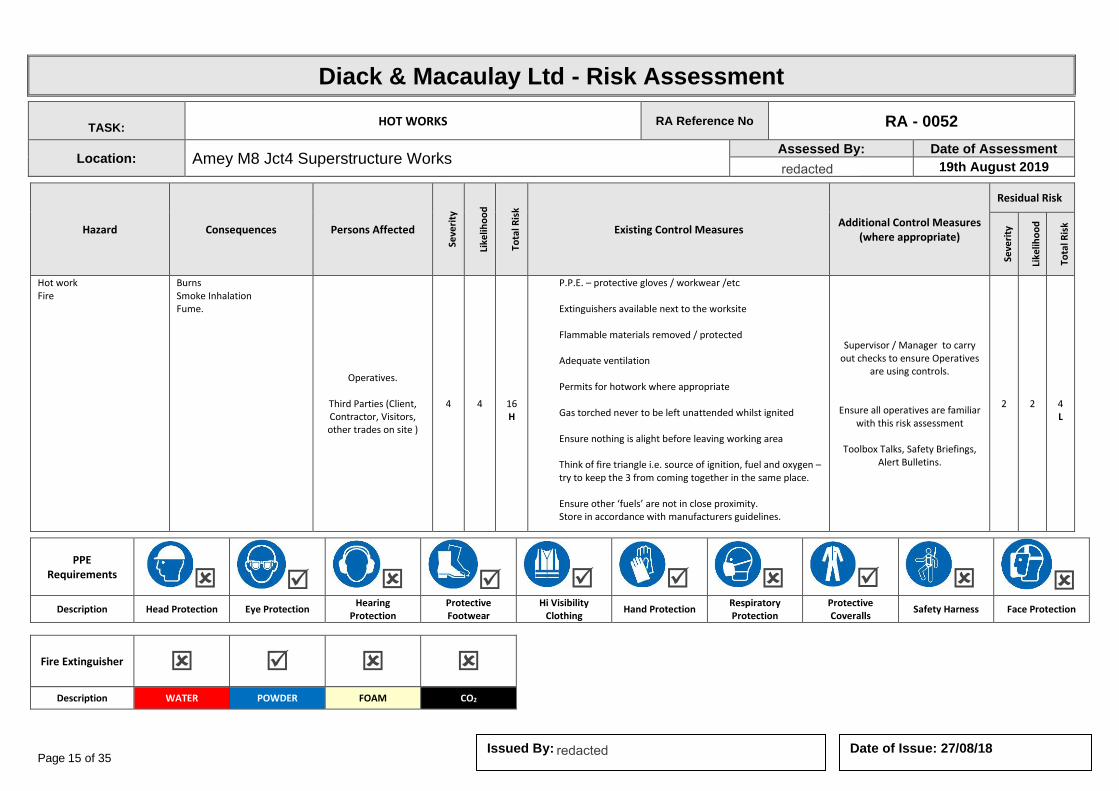
Page 15 of 35 Date of Issue: 27/08/18 Issued By:
Diack & Macaulay Ltd - Risk Assessment
TASK: HOT WORKS RA Reference No RA - 0052
Location: Amey M8 Jct4 Superstructure Works Assessed By: Date of Assessment
19th August 2019
Hazard Consequences Persons Affected
Seve
rity
Like
liho
od
Tota
l Ris
k
Existing Control Measures Additional Control Measures
(where appropriate)
Residual Risk
Seve
rity
Like
liho
od
Tota
l Ris
k
Hot work Fire
Burns Smoke Inhalation Fume.
Operatives.
Third Parties (Client, Contractor, Visitors, other trades on site )
4 4
16 H
P.P.E. – protective gloves / workwear /etc Extinguishers available next to the worksite Flammable materials removed / protected Adequate ventilation Permits for hotwork where appropriate Gas torched never to be left unattended whilst ignited Ensure nothing is alight before leaving working area Think of fire triangle i.e. source of ignition, fuel and oxygen – try to keep the 3 from coming together in the same place. Ensure other ‘fuels’ are not in close proximity. Store in accordance with manufacturers guidelines.
Supervisor / Manager to carry out checks to ensure Operatives
are using controls.
Ensure all operatives are familiar with this risk assessment
Toolbox Talks, Safety Briefings,
Alert Bulletins.
2 2
4 L
PPE Requirements
Description Head Protection Eye Protection Hearing
Protection Protective Footwear
Hi Visibility Clothing
Hand Protection Respiratory Protection
Protective Coveralls
Safety Harness Face Protection
Fire Extinguisher
Description WATER POWDER FOAM CO2
redacted 11(2)
redacted 11(2)
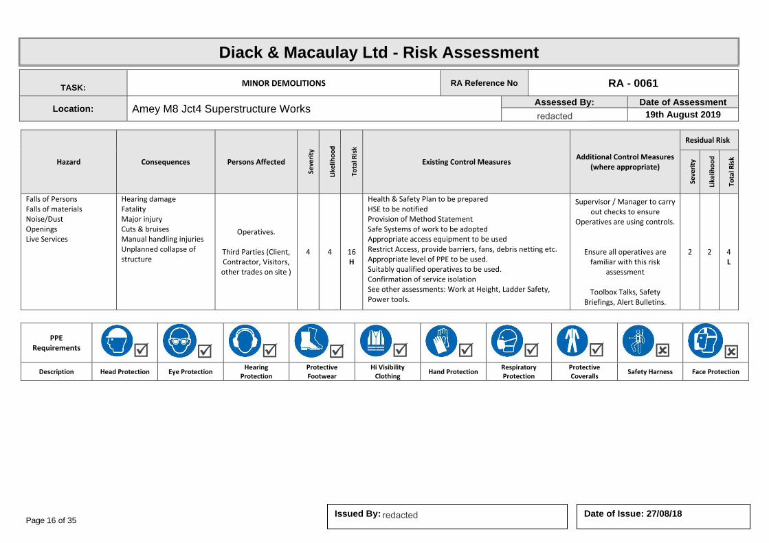
Page 16 of 35 Date of Issue: 27/08/18 Issued By:
Diack & Macaulay Ltd - Risk Assessment
TASK: MINOR DEMOLITIONS RA Reference No RA - 0061
Location: Amey M8 Jct4 Superstructure Works Assessed By: Date of Assessment
19th August 2019
Hazard Consequences Persons Affected
Seve
rity
Like
liho
od
Tota
l Ris
k
Existing Control Measures Additional Control Measures
(where appropriate)
Residual Risk
Seve
rity
Like
liho
od
Tota
l Ris
k
Falls of Persons Falls of materials Noise/Dust Openings Live Services
Hearing damage Fatality Major injury Cuts & bruises Manual handling injuries Unplanned collapse of structure
Operatives.
Third Parties (Client, Contractor, Visitors, other trades on site )
4 4
16 H
Health & Safety Plan to be prepared HSE to be notified Provision of Method Statement Safe Systems of work to be adopted Appropriate access equipment to be used Restrict Access, provide barriers, fans, debris netting etc. Appropriate level of PPE to be used. Suitably qualified operatives to be used. Confirmation of service isolation See other assessments: Work at Height, Ladder Safety, Power tools.
Supervisor / Manager to carry out checks to ensure
Operatives are using controls.
Ensure all operatives are familiar with this risk
assessment
Toolbox Talks, Safety Briefings, Alert Bulletins.
2 2
4 L
PPE Requirements
Description Head Protection Eye Protection Hearing
Protection Protective Footwear
Hi Visibility Clothing
Hand Protection Respiratory Protection
Protective Coveralls
Safety Harness Face Protection
redacted 11(2)
redacted 11(2)

Page 17 of 35 Date of Issue: 27/08/18 Issued By:
Diack & Macaulay Ltd - Risk Assessment
TASK: NOISE RA Reference No RA - 0063
Location: Amey M8 Jct4 Superstructure Works Assessed By: Date of Assessment
19th August 2019
Hazard Consequences Persons Affected
Seve
rity
Like
liho
od
Tota
l Ris
k
Existing Control Measures Additional Control Measures
(where appropriate)
Residual Risk
Seve
rity
Like
liho
od
Tota
l Ris
k
Noise Damage to hearing Inability to hear warnings, instructions
Operatives.
Third Parties (Client, Contractor, Visitors, other trades on site )
3 3
9 M
Limited use of powered equipment Suitable hearing protection worn by operatives Members of the public, tenants, etc. not directly exposed to high or prolonged noise levels
Supervisor / Manager to carry out checks to ensure
Operatives are using controls.
Ensure all operatives are familiar with this risk
assessment
Toolbox Talks, Safety Briefings, Alert Bulletins.
2 2
4 L
PPE Requirements
Description Head Protection Eye Protection Hearing
Protection Protective Footwear
Hi Visibility Clothing
Hand Protection Respiratory Protection
Protective Coveralls
Safety Harness Face Protection
redacted 11(2)
redacted 11(2)
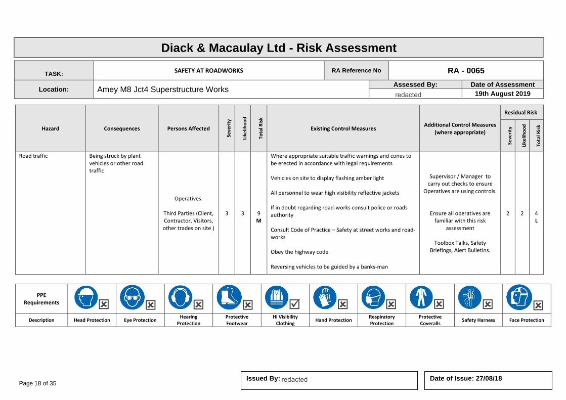
Page 18 of 35 Date of Issue: 27/08/18 Issued By:
Diack & Macaulay Ltd - Risk Assessment
TASK: SAFETY AT ROADWORKS RA Reference No RA - 0065
Location: Amey M8 Jct4 Superstructure Works Assessed By: Date of Assessment
19th August 2019
Hazard Consequences Persons Affected
Seve
rity
Like
liho
od
Tota
l Ris
k
Existing Control Measures Additional Control Measures
(where appropriate)
Residual Risk
Seve
rity
Like
liho
od
Tota
l Ris
k
Road traffic
Being struck by plant vehicles or other road traffic
Operatives.
Third Parties (Client, Contractor, Visitors, other trades on site )
3 3
9 M
Where appropriate suitable traffic warnings and cones to be erected in accordance with legal requirements Vehicles on site to display flashing amber light All personnel to wear high visibility reflective jackets If in doubt regarding road-works consult police or roads authority Consult Code of Practice – Safety at street works and road-works Obey the highway code Reversing vehicles to be guided by a banks-man
Supervisor / Manager to carry out checks to ensure
Operatives are using controls.
Ensure all operatives are familiar with this risk
assessment
Toolbox Talks, Safety Briefings, Alert Bulletins.
2 2
4 L
PPE Requirements
Description Head Protection Eye Protection Hearing
Protection Protective Footwear
Hi Visibility Clothing
Hand Protection Respiratory Protection
Protective Coveralls
Safety Harness Face Protection
redacted 11(2)
redacted 11(2)
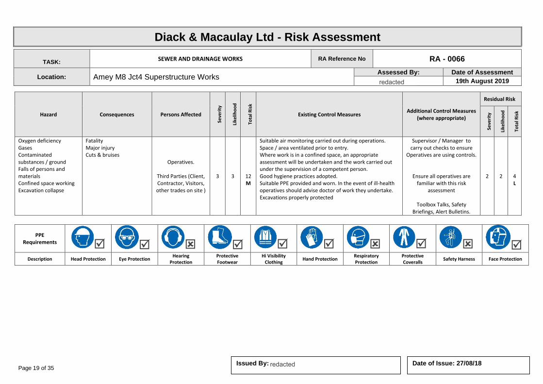
Page 19 of 35 Date of Issue: 27/08/18 Issued By:
Diack & Macaulay Ltd - Risk Assessment
TASK: SEWER AND DRAINAGE WORKS RA Reference No RA - 0066
Location: Amey M8 Jct4 Superstructure Works Assessed By: Date of Assessment
19th August 2019
Hazard Consequences Persons Affected
Seve
rity
Like
liho
od
Tota
l Ris
k
Existing Control Measures Additional Control Measures
(where appropriate)
Residual Risk
Seve
rity
Like
liho
od
Tota
l Ris
k
Oxygen deficiency Gases Contaminated substances / ground Falls of persons and materials Confined space working Excavation collapse
Fatality Major injury Cuts & bruises
Operatives.
Third Parties (Client, Contractor, Visitors, other trades on site )
3 3
12 M
Suitable air monitoring carried out during operations. Space / area ventilated prior to entry. Where work is in a confined space, an appropriate assessment will be undertaken and the work carried out under the supervision of a competent person. Good hygiene practices adopted. Suitable PPE provided and worn. In the event of ill-health operatives should advise doctor of work they undertake. Excavations properly protected
Supervisor / Manager to carry out checks to ensure
Operatives are using controls.
Ensure all operatives are familiar with this risk
assessment
Toolbox Talks, Safety Briefings, Alert Bulletins.
2 2
4 L
PPE Requirements
Description Head Protection Eye Protection Hearing
Protection Protective Footwear
Hi Visibility Clothing
Hand Protection Respiratory Protection
Protective Coveralls
Safety Harness Face Protection
redacted 11(2)
redacted 11(2)
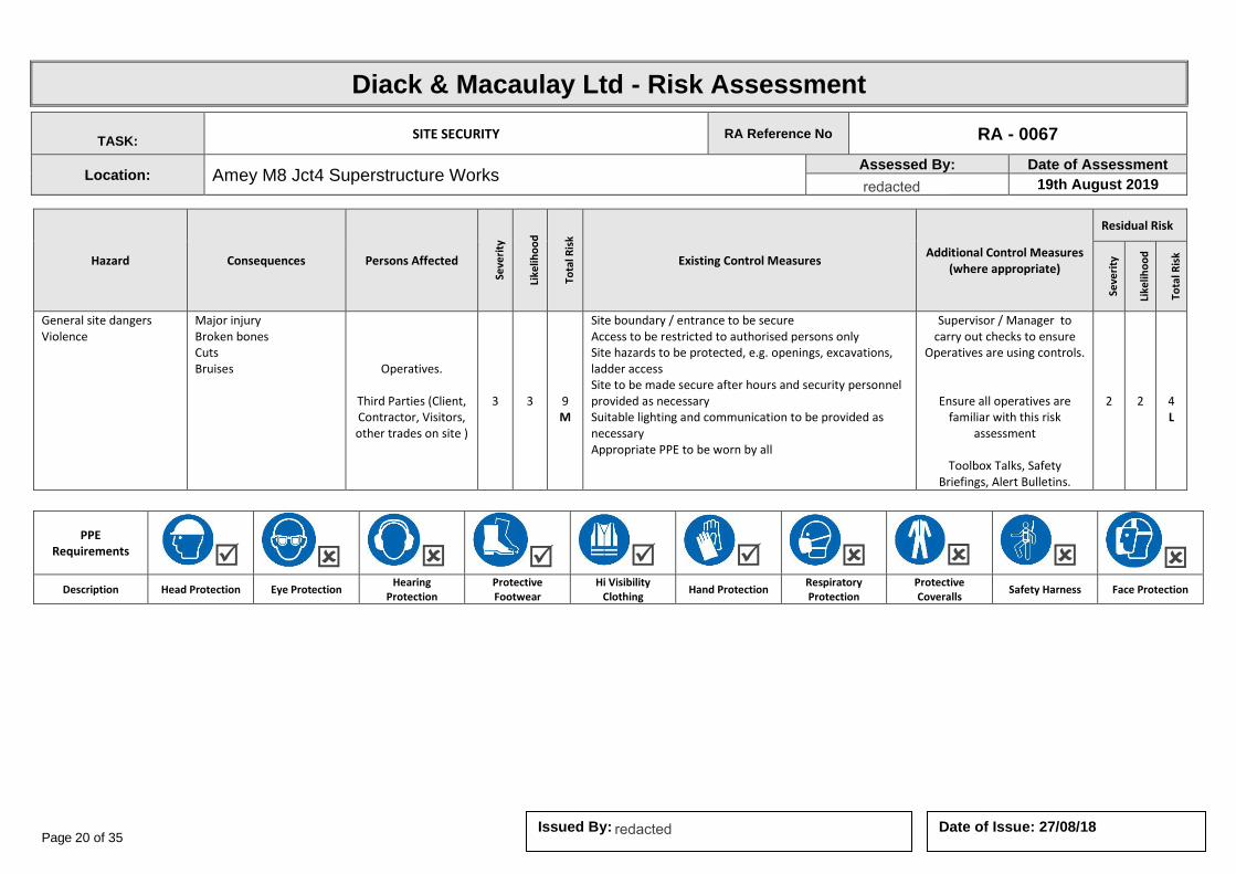
Page 20 of 35 Date of Issue: 27/08/18 Issued By:
Diack & Macaulay Ltd - Risk Assessment
TASK: SITE SECURITY RA Reference No RA - 0067
Location: Amey M8 Jct4 Superstructure Works Assessed By: Date of Assessment
19th August 2019
Hazard Consequences Persons Affected
Seve
rity
Like
liho
od
Tota
l Ris
k
Existing Control Measures Additional Control Measures
(where appropriate)
Residual Risk
Seve
rity
Like
liho
od
Tota
l Ris
k
General site dangers Violence
Major injury Broken bones Cuts Bruises
Operatives.
Third Parties (Client, Contractor, Visitors, other trades on site )
3 3
9 M
Site boundary / entrance to be secure Access to be restricted to authorised persons only Site hazards to be protected, e.g. openings, excavations, ladder access Site to be made secure after hours and security personnel provided as necessary Suitable lighting and communication to be provided as necessary Appropriate PPE to be worn by all
Supervisor / Manager to carry out checks to ensure
Operatives are using controls.
Ensure all operatives are familiar with this risk
assessment
Toolbox Talks, Safety Briefings, Alert Bulletins.
2 2
4 L
PPE Requirements
Description Head Protection Eye Protection Hearing
Protection Protective Footwear
Hi Visibility Clothing
Hand Protection Respiratory Protection
Protective Coveralls
Safety Harness Face Protection
redacted 11(2)
redacted 11(2)
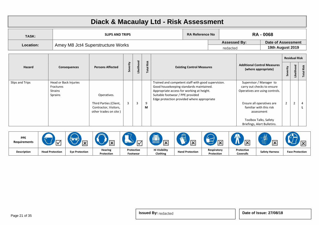
Page 21 of 35 Date of Issue: 27/08/18 Issued By:
Diack & Macaulay Ltd - Risk Assessment
TASK: SLIPS AND TRIPS RA Reference No RA - 0068
Location: Amey M8 Jct4 Superstructure Works Assessed By: Date of Assessment
19th August 2019
Hazard Consequences Persons Affected
Seve
rity
Like
liho
od
Tota
l Ris
k
Existing Control Measures Additional Control Measures
(where appropriate)
Residual Risk
Seve
rity
Like
liho
od
Tota
l Ris
k
Slips and Trips Head or Back Injuries Fractures Strains Sprains Operatives.
Third Parties (Client, Contractor, Visitors, other trades on site )
3 3
9 M
Trained and competent staff with good supervision. Good housekeeping standards maintained. Appropriate access for working at height. Suitable footwear / PPE provided Edge protection provided where appropriate
Supervisor / Manager to carry out checks to ensure
Operatives are using controls.
Ensure all operatives are familiar with this risk
assessment
Toolbox Talks, Safety Briefings, Alert Bulletins.
2 2
4 L
PPE Requirements
Description Head Protection Eye Protection Hearing
Protection Protective Footwear
Hi Visibility Clothing
Hand Protection Respiratory Protection
Protective Coveralls
Safety Harness Face Protection
redacted 11(2)
redacted 11(2)
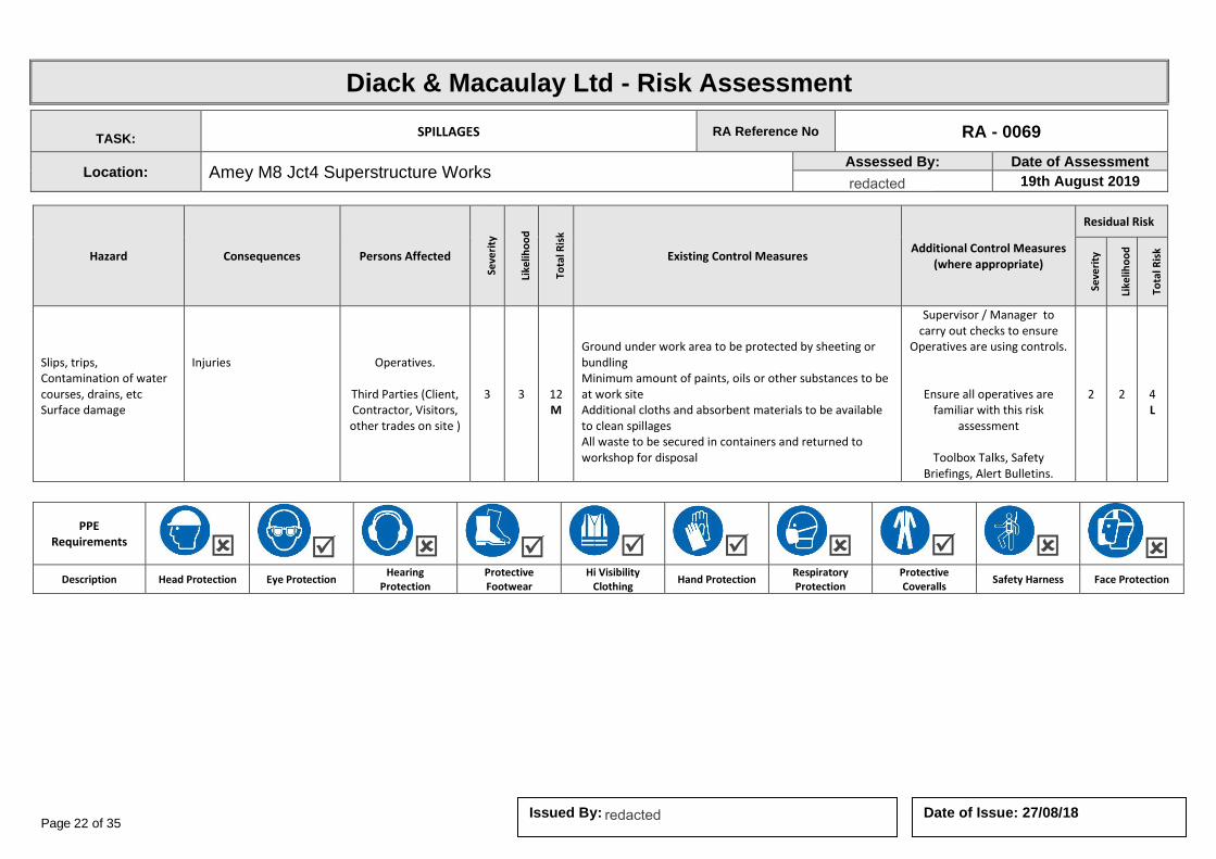
Page 22 of 35 Date of Issue: 27/08/18 Issued By:
Diack & Macaulay Ltd - Risk Assessment
TASK: SPILLAGES RA Reference No RA - 0069
Location: Amey M8 Jct4 Superstructure Works Assessed By: Date of Assessment
19th August 2019
Hazard Consequences Persons Affected
Seve
rity
Like
liho
od
Tota
l Ris
k
Existing Control Measures Additional Control Measures
(where appropriate)
Residual Risk
Seve
rity
Like
liho
od
Tota
l Ris
k
Slips, trips, Contamination of water courses, drains, etc Surface damage
Injuries Operatives.
Third Parties (Client, Contractor, Visitors, other trades on site )
3 3
12 M
Ground under work area to be protected by sheeting or bundling Minimum amount of paints, oils or other substances to be at work site Additional cloths and absorbent materials to be available to clean spillages All waste to be secured in containers and returned to workshop for disposal
Supervisor / Manager to carry out checks to ensure
Operatives are using controls.
Ensure all operatives are familiar with this risk
assessment
Toolbox Talks, Safety Briefings, Alert Bulletins.
2 2
4 L
PPE Requirements
Description Head Protection Eye Protection Hearing
Protection Protective Footwear
Hi Visibility Clothing
Hand Protection Respiratory Protection
Protective Coveralls
Safety Harness Face Protection
redacted 11(2)
redacted 11(2)

Page 23 of 35 Date of Issue: 27/08/18 Issued By:
Diack & Macaulay Ltd - Risk Assessment
TASK: TRAFFIC MOVEMENTS RA Reference No RA - 0072
Location: Amey M8 Jct4 Superstructure Works Assessed By: Date of Assessment
19th August 2019
Hazard Consequences Persons Affected
Seve
rity
Like
liho
od
Tota
l Ris
k
Existing Control Measures Additional Control Measures
(where appropriate)
Residual Risk
Seve
rity
Like
liho
od
Tota
l Ris
k
Contact with other vehicles / structures Collision / accident
Injury Fatality Property Damage
Operatives.
Third Parties (Client, Contractor, Visitors, other trades on site )
4 4
16 H
Traffic movements to be restricted and planned Banksman to be used at all times Areas to be protected by barriers Speed to be reduced to minimum Reversing movements to be restricted and controlled by Banksman Loads to be secured Segregation of pedestrians where possible Operation of one way system if possible
Supervisor / Manager to carry out checks to ensure
Operatives are using controls.
Ensure all operatives are familiar with this risk
assessment
Toolbox Talks, Safety Briefings, Alert Bulletins.
2 2
4 L
PPE Requirements
Description Head Protection Eye Protection Hearing
Protection Protective Footwear
Hi Visibility Clothing
Hand Protection Respiratory Protection
Protective Coveralls
Safety Harness Face Protection
redacted 11(2)
redacted 11(2)
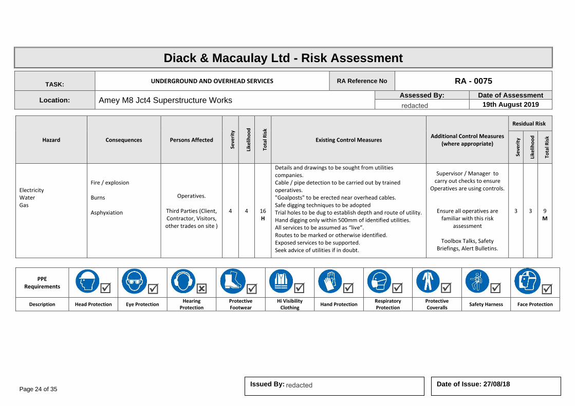
Page 24 of 35 Date of Issue: 27/08/18 Issued By:
Diack & Macaulay Ltd - Risk Assessment
TASK: UNDERGROUND AND OVERHEAD SERVICES RA Reference No RA - 0075
Location: Amey M8 Jct4 Superstructure Works Assessed By: Date of Assessment
19th August 2019
Hazard Consequences Persons Affected
Seve
rity
Like
liho
od
Tota
l Ris
k
Existing Control Measures Additional Control Measures
(where appropriate)
Residual Risk
Seve
rity
Like
liho
od
Tota
l Ris
k
Electricity Water Gas
Fire / explosion Burns Asphyxiation
Operatives.
Third Parties (Client, Contractor, Visitors, other trades on site )
4 4
16 H
Details and drawings to be sought from utilities companies. Cable / pipe detection to be carried out by trained operatives. "Goalposts" to be erected near overhead cables. Safe digging techniques to be adopted Trial holes to be dug to establish depth and route of utility. Hand digging only within 500mm of identified utilities. All services to be assumed as “live”. Routes to be marked or otherwise identified. Exposed services to be supported. Seek advice of utilities if in doubt.
Supervisor / Manager to carry out checks to ensure
Operatives are using controls.
Ensure all operatives are familiar with this risk
assessment
Toolbox Talks, Safety Briefings, Alert Bulletins.
3 3
9 M
PPE Requirements
Description Head Protection Eye Protection Hearing
Protection Protective Footwear
Hi Visibility Clothing
Hand Protection Respiratory Protection
Protective Coveralls
Safety Harness Face Protection
redacted 11(2)
redacted 11(2)
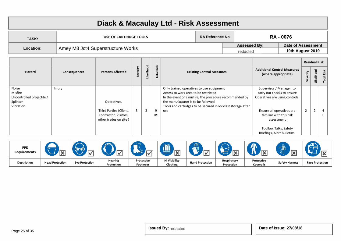
Page 25 of 35 Date of Issue: 27/08/18 Issued By:
Diack & Macaulay Ltd - Risk Assessment
TASK: USE OF CARTRIDGE TOOLS RA Reference No RA - 0076
Location: Amey M8 Jct4 Superstructure Works Assessed By: Date of Assessment
19th August 2019
Hazard Consequences Persons Affected
Seve
rity
Like
liho
od
Tota
l Ris
k
Existing Control Measures Additional Control Measures
(where appropriate)
Residual Risk
Seve
rity
Like
liho
od
Tota
l Ris
k
Noise Misfire Uncontrolled projectile / Splinter Vibration
Injury
Operatives.
Third Parties (Client, Contractor, Visitors, other trades on site )
3 3
9 M
Only trained operatives to use equipment Access to work area to be restricted In the event of a misfire, the procedure recommended by the manufacturer is to be followed Tools and cartridges to be secured in lockfast storage after use
Supervisor / Manager to carry out checks to ensure
Operatives are using controls.
Ensure all operatives are familiar with this risk
assessment
Toolbox Talks, Safety Briefings, Alert Bulletins.
2 2
4 L
PPE Requirements
Description Head Protection Eye Protection Hearing
Protection Protective Footwear
Hi Visibility Clothing
Hand Protection Respiratory Protection
Protective Coveralls
Safety Harness Face Protection
redacted 11(2)
redacted 11(2)
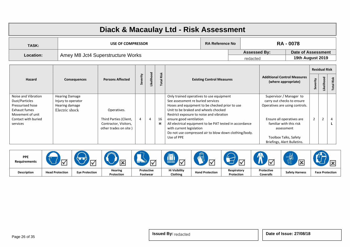
Page 26 of 35 Date of Issue: 27/08/18 Issued By:
Diack & Macaulay Ltd - Risk Assessment
TASK: USE OF COMPRESSOR RA Reference No RA - 0078
Location: Amey M8 Jct4 Superstructure Works Assessed By: Date of Assessment
19th August 2019
Hazard Consequences Persons Affected
Seve
rity
Like
liho
od
Tota
l Ris
k
Existing Control Measures Additional Control Measures
(where appropriate)
Residual Risk
Seve
rity
Like
liho
od
Tota
l Ris
k
Noise and Vibration Dust/Particles Pressurised hose Exhaust fumes Movement of unit Contact with buried services
Hearing Damage Injury to operator Hearing damage
Electric shock
Operatives.
Third Parties (Client, Contractor, Visitors, other trades on site )
4 4
16 H
Only trained operatives to use equipment See assessment re buried services Hoses and equipment to be checked prior to use Unit to be braked and wheels chocked Restrict exposure to noise and vibration ensure good ventilation All electrical equipment to be PAT tested in accordance with current legislation Do not use compressed air to blow down clothing/body. Use of PPE
Supervisor / Manager to carry out checks to ensure
Operatives are using controls.
Ensure all operatives are familiar with this risk
assessment
Toolbox Talks, Safety Briefings, Alert Bulletins.
2 2
4 L
PPE Requirements
Description Head Protection Eye Protection Hearing
Protection Protective Footwear
Hi Visibility Clothing
Hand Protection Respiratory Protection
Protective Coveralls
Safety Harness Face Protection
redacted 11(2)
redacted 11(2)

Page 27 of 35 Date of Issue: 27/08/18 Issued By:
Diack & Macaulay Ltd - Risk Assessment
TASK: USE OF CRANES AND EXCAVATORS RA Reference No RA - 0079
Location: Amey M8 Jct4 Superstructure Works Assessed By: Date of Assessment
19th August 2019
Hazard Consequences Persons Affected
Seve
rity
Like
liho
od
Tota
l Ris
k
Existing Control Measures Additional Control Measures
(where appropriate)
Residual Risk
Seve
rity
Like
liho
od
Tota
l Ris
k
Overturning of plant Plant operations, contact with moving machinery Trapping Falling materials / unintentional collapse Noise, dust, debris O/head and underground services
Property damage Major Injury
Operatives.
Third Parties (Client, Contractor, Visitors, other trades on site )
3 3
9 M
Plant and operators certification to be checked Lifting operations to be planned in accordance with LOLER 98 Suitable area to be prepared for lifting activities Protection provided for underground / o/head services Banksman to be used at all times and adequate communication established All operatives and others to be withdrawn from the area to a safe location Suitable PPE to be worn
Supervisor / Manager to carry out checks to ensure Operatives are using controls.
Ensure all operatives are familiar with this risk assessment
Toolbox Talks, Safety Briefings, Alert Bulletins.
2 2
4 L
PPE Requirements
Description Head Protection Eye Protection Hearing
Protection Protective Footwear
Hi Visibility Clothing
Hand Protection Respiratory Protection
Protective Coveralls
Safety Harness Face Protection
redacted 11(2)
redacted 11(2)
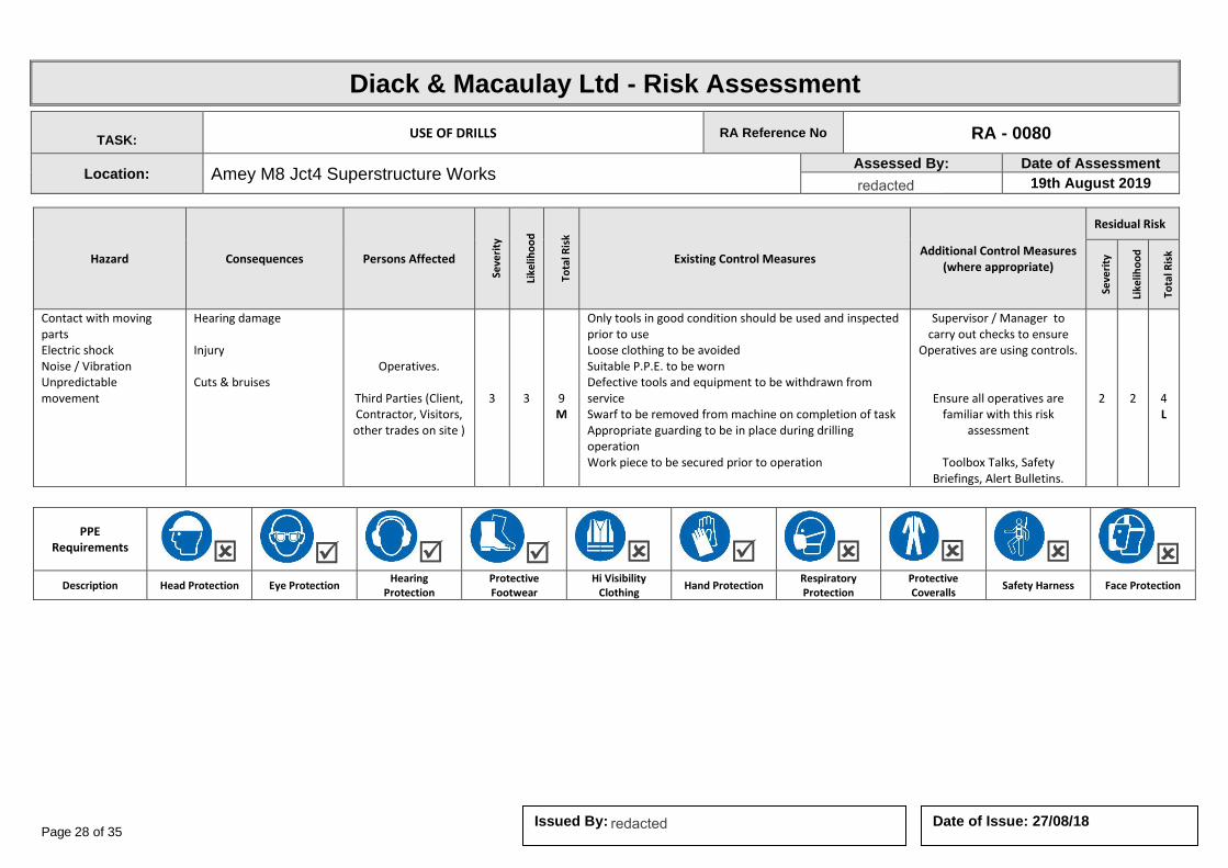
Page 28 of 35 Date of Issue: 27/08/18 Issued By:
Diack & Macaulay Ltd - Risk Assessment
TASK: USE OF DRILLS RA Reference No RA - 0080
Location: Amey M8 Jct4 Superstructure Works Assessed By: Date of Assessment
19th August 2019
Hazard Consequences Persons Affected
Seve
rity
Like
liho
od
Tota
l Ris
k
Existing Control Measures Additional Control Measures
(where appropriate)
Residual Risk
Seve
rity
Like
liho
od
Tota
l Ris
k
Contact with moving parts Electric shock Noise / Vibration Unpredictable movement
Hearing damage Injury Cuts & bruises
Operatives.
Third Parties (Client, Contractor, Visitors, other trades on site )
3 3
9 M
Only tools in good condition should be used and inspected prior to use Loose clothing to be avoided Suitable P.P.E. to be worn Defective tools and equipment to be withdrawn from service Swarf to be removed from machine on completion of task Appropriate guarding to be in place during drilling operation Work piece to be secured prior to operation
Supervisor / Manager to carry out checks to ensure
Operatives are using controls.
Ensure all operatives are familiar with this risk
assessment
Toolbox Talks, Safety Briefings, Alert Bulletins.
2 2
4 L
PPE Requirements
Description Head Protection Eye Protection Hearing
Protection Protective Footwear
Hi Visibility Clothing
Hand Protection Respiratory Protection
Protective Coveralls
Safety Harness Face Protection
redacted 11(2)
redacted 11(2)

Page 29 of 35 Date of Issue: 27/08/18 Issued By:
Diack & Macaulay Ltd - Risk Assessment
TASK: USE OF HAND HELD GRINDERS RA Reference No RA - 0083
Location: Amey M8 Jct4 Superstructure Works Assessed By: Date of Assessment
19th August 2019
Hazard Consequences Persons Affected
Seve
rity
Like
liho
od
Tota
l Ris
k
Existing Control Measures Additional Control Measures
(where appropriate)
Residual Risk
Seve
rity
Like
liho
od
Tota
l Ris
k
Contact with blade or disc Noise / vibration Sharp edges Dust / Fume Bursting disc Changing Blade Falling materials Hotwork - fire Handling
Hearing damage Cuts & bruises Respiratory Issues Burns
Operatives.
Third Parties (Client, Contractor, Visitors, other trades on site )
3 3
9 M
Trained Operative Suitable guarding to be provided and adjusted Machine to be adequately maintained Safe system of work to be adopted when maintaining or changing blade/disc Restricted operation and/or work rotation If prolonged use, dust capture to be used Tool to be firmly gripped / supported
Suitable fire extinguisher to be at hand if generating sparks.
Supervisor / Manager to carry out checks to ensure
Operatives are using controls.
Ensure all operatives are familiar with this risk
assessment
Toolbox Talks, Safety Briefings, Alert Bulletins.
2 2
4 L
PPE Requirements
Description Head Protection Eye Protection Hearing
Protection Protective Footwear
Hi Visibility Clothing
Hand Protection Respiratory Protection
Protective Coveralls
Safety Harness Face Protection
Fire Extinguisher
Description WATER POWDER FOAM CO2
redacted 11(2)
redacted 11(2)

Page 30 of 35 Date of Issue: 27/08/18 Issued By:
Diack & Macaulay Ltd - Risk Assessment
TASK: USE OF PETROL or DIESEL RA Reference No RA - 0087
Location: Amey M8 Jct4 Superstructure Works Assessed By: Date of Assessment
19th August 2019
Hazard Consequences Persons Affected
Seve
rity
Like
liho
od
Tota
l Ris
k
Existing Control Measures Additional Control Measures
(where appropriate)
Residual Risk
Seve
rity
Like
liho
od
Tota
l Ris
k
Fire Material handling Spill
Burns Ground contamination
Operatives.
Third Parties (Client, Contractor, Visitors, other trades on site )
3 3
9 M
Fuel must only be carried in approved containers All plant and equipment to be turned off whilst being re-fuelled Re-fuelling to be carried out in well ventilated areas No smoking or naked lights in the vicinity during re-fuelling Spillages should be cleaned or absorbed using sand or earth Fuel bowsers where used must have suitable bunding
Supervisor / Manager to carry out checks to ensure
Operatives are using controls.
Ensure all operatives are familiar with this risk
assessment
Toolbox Talks, Safety Briefings, Alert Bulletins.
2 2
4 L
PPE Requirements
Description Head Protection Eye Protection Hearing
Protection Protective Footwear
Hi Visibility Clothing
Hand Protection Respiratory Protection
Protective Coveralls
Safety Harness Face Protection
Fire Extinguisher
Description WATER POWDER FOAM CO2
redacted 11(2)
redacted 11(2)

Page 31 of 35 Date of Issue: 27/08/18 Issued By:
Diack & Macaulay Ltd - Risk Assessment
TASK: USE OF PPE RA Reference No RA - 0090
Location: Amey M8 Jct4 Superstructure Works Assessed By: Date of Assessment
19th August 2019
Hazard Consequences Persons Affected
Seve
rity
Like
liho
od
Tota
l Ris
k
Existing Control Measures Additional Control Measures
(where appropriate)
Residual Risk
Seve
rity
Like
liho
od
Tota
l Ris
k
Noise / Dust / Fume / Debris Falling Materials Substances Weather Machine Operation Sharps Site Traffic / Plant operations
Hearing damage Fatal Injuries Oxygen deficiency Permanent Disfigurement Major Injury
Operatives.
Third Parties (Client, Contractor, Visitors, other trades on site )
3 3
9 M
Safety helmets, safety footwear and high visibility clothing to be worn on all sites Hearing and eye protection to be worn when operating machinery or if exposed to noise or debris Respiratory protection to be worn when exposed to dusts and other materials Suitable clothing to be worn in adverse weather conditions Gloves to be worn to protect the skin from cuts and irritants Knee pads and other PPE to be worn as appropriate PPE should be worn as recommended by manufacturers and suppliers All PPE to be adequately stored and maintained
Supervisor / Manager to carry out checks to ensure
Operatives are using controls.
Ensure all operatives are familiar with this risk
assessment
Toolbox Talks, Safety Briefings, Alert Bulletins.
2 2
4 L
PPE Requirements
Description Head Protection Eye Protection Hearing
Protection Protective Footwear
Hi Visibility Clothing
Hand Protection Respiratory Protection
Protective Coveralls
Safety Harness Face Protection
redacted 11(2)
redacted 11(2)
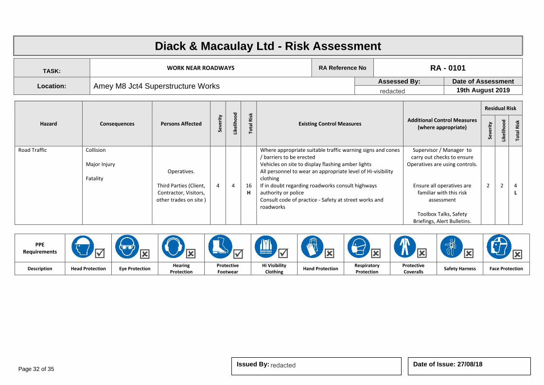
Page 32 of 35 Date of Issue: 27/08/18 Issued By:
Diack & Macaulay Ltd - Risk Assessment
TASK: WORK NEAR ROADWAYS RA Reference No RA - 0101
Location: Amey M8 Jct4 Superstructure Works Assessed By: Date of Assessment
19th August 2019
Hazard Consequences Persons Affected
Seve
rity
Like
liho
od
Tota
l Ris
k
Existing Control Measures Additional Control Measures
(where appropriate)
Residual Risk
Seve
rity
Like
liho
od
Tota
l Ris
k
Road Traffic Collision Major Injury Fatality
Operatives.
Third Parties (Client, Contractor, Visitors, other trades on site )
4 4
16 H
Where appropriate suitable traffic warning signs and cones / barriers to be erected Vehicles on site to display flashing amber lights All personnel to wear an appropriate level of Hi-visibility clothing If in doubt regarding roadworks consult highways authority or police Consult code of practice - Safety at street works and roadworks
Supervisor / Manager to carry out checks to ensure
Operatives are using controls.
Ensure all operatives are familiar with this risk
assessment
Toolbox Talks, Safety Briefings, Alert Bulletins.
2 2
4 L
PPE Requirements
Description Head Protection Eye Protection Hearing
Protection Protective Footwear
Hi Visibility Clothing
Hand Protection Respiratory Protection
Protective Coveralls
Safety Harness Face Protection
redacted 11(2)
redacted 11(2)
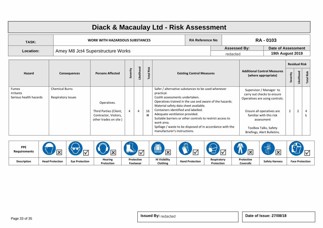
Page 33 of 35 Date of Issue: 27/08/18 Issued By:
Diack & Macaulay Ltd - Risk Assessment
TASK: WORK WITH HAZARDOUS SUBSTANCES RA Reference No RA - 0103
Location: Amey M8 Jct4 Superstructure Works Assessed By: Date of Assessment
19th August 2019
Hazard Consequences Persons Affected
Seve
rity
Like
liho
od
Tota
l Ris
k
Existing Control Measures Additional Control Measures
(where appropriate)
Residual Risk
Seve
rity
Like
liho
od
Tota
l Ris
k
Fumes Irritants Serious health hazards
Chemical Burns Respiratory Issues
Operatives.
Third Parties (Client, Contractor, Visitors, other trades on site )
4 4
16 H
Safer / alternative substances to be used whenever practical. Coshh assessments undertaken. Operatives trained in the use and aware of the hazards. Material safety data sheet available. Containers identified and labelled. Adequate ventilation provided. Suitable barriers or other controls to restrict access to work area. Spillage / waste to be disposed of in accordance with the manufacturer's instructions.
Supervisor / Manager to carry out checks to ensure
Operatives are using controls.
Ensure all operatives are familiar with this risk
assessment
Toolbox Talks, Safety Briefings, Alert Bulletins.
2 2
4 L
PPE Requirements
Description Head Protection Eye Protection Hearing
Protection Protective Footwear
Hi Visibility Clothing
Hand Protection Respiratory Protection
Protective Coveralls
Safety Harness Face Protection
redacted 11(2)
redacted 11(2)

Page 34 of 35 Date of Issue: 27/08/18 Issued By:
Diack & Macaulay Ltd - Risk Assessment
TASK: VEHICLE COLLISION RA Reference No RA - 0110
Location: Amey M8 Jct4 Superstructure Works Assessed By: Date of Assessment
19th August 2019
Hazard Consequences Persons Affected
Seve
rity
Like
liho
od
Tota
l Ris
k
Existing Control Measures Additional Control Measures
(where appropriate)
Residual Risk
Seve
rity
Like
liho
od
Tota
l Ris
k
Vehicle collision Major injuries. Potentially fatal . Crushing and lacerations. Cuts, bruises
Operatives.
Third Parties (Client, Contractor, Visitors, other trades on site )
4 4
16 H
Safe systems of work implemented: Delivery route and times agreed with client. Banksman will be used during all reversing movements. Parking areas for vehicles / skips to be segregated where possible & warning signage displayed. Vehicles maintained. Drivers licensed and authorised. Appropriate levels of p.p.e. Used - hard hats, high – viz vests.
Supervisor / Manager to carry out checks to ensure
Operatives are using controls.
Ensure all operatives are familiar with this risk
assessment
Toolbox Talks, Safety Briefings, Alert Bulletins.
4 2
8 M
PPE Requirements
Description Head Protection Eye Protection Hearing
Protection Protective Footwear
Hi Visibility Clothing
Hand Protection Respiratory Protection
Protective Coveralls
Safety Harness Face Protection
redacted 11(2)
redacted 11(2)
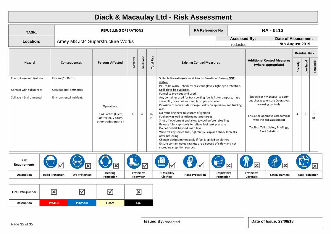
Page 35 of 35 Date of Issue: 27/08/18 Issued By:
Diack & Macaulay Ltd - Risk Assessment
TASK: REFUELLING OPERATIONS RA Reference No RA - 0113
Location: Amey M8 Jct4 Superstructure Works Assessed By: Date of Assessment
19th August 2019
Hazard Consequences Persons Affected
Seve
rity
Like
liho
od
Tota
l Ris
k
Existing Control Measures Additional Control Measures
(where appropriate)
Residual Risk
Seve
rity
Like
liho
od
Tota
l Ris
k
Fuel spillage and ignition Contact with substances Spillage - Environmental
Fire and/or Burns Occupational dermatitis Environmental incident.
Operatives.
Third Parties (Client, Contractor, Visitors, other trades on site )
4 4
16 H
Suitable fire extinguisher at hand – Powder or Foam – NOT water. PPE to be worn – chemical resistant gloves, light eye protection. Spill kit to be available. Funnel to provided and used. Any container used for transporting fuel is fit for purpose, has a sealed lid, does not leak and is properly labelled. Provision of secure safe storage facility on appliance and fuelling aids No refuelling near to sources of ignition Fuel only in well ventilated outdoor areas Shut off equipment and allow to cool before refuelling Release filler cap slowly to relieve fuel tank pressure Do not overfill beyond ‘max’ level Wipe off any spilled fuel, tighten fuel cap and check for leaks after refuelling Change clothes immediately if fuel is spilled on clothes Ensure contaminated rags etc are disposed of safely and not stored near ignition sources.
Supervisor / Manager to carry out checks to ensure Operatives
are using controls.
Ensure all operatives are familiar with this risk assessment
Toolbox Talks, Safety Briefings,
Alert Bulletins.
3 3
9 M
PPE Requirements
Description Head Protection Eye Protection Hearing
Protection Protective Footwear
Hi Visibility Clothing
Hand Protection Respiratory Protection
Protective Coveralls
Safety Harness Face Protection
Fire Extinguisher
Description WATER POWDER FOAM CO2
redacted 11(2)
redacted 11(2)
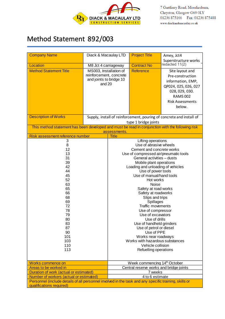
Company Name Diack & Macaulay LTD Project Title Amey, Jct4 Superstructure works
Location M8 Jct 4 carriageway Contract No
Method Statement Title MS003, Installation of reinforcement, concrete and joints to bridge 10
and 20
Reference Site layout and Pre-construction
information, EMP, QP024, 025, 026, 027
028, 029, 030. RAMS 002
Risk Assessments below.
Description of Works Supply, install of reinforcement, pouring of concrete and install of
type 1 bridge joints This method statement has been developed and must be read in conjunction with the following risk
assessments. Risk assessment reference number Title 3
8 12 13 31 39 42 44 45 52 63 65 66 68 69 72 78 79 80 83 87 90
101 103 110 113
Lifting operations Use of abrasive wheels
Cement and concrete works Use of compressed air/pneumatic tools
General activities – dusts Mobile plant operations
Loading and unloading of vehicles Use of power tools
Use of manual/hand tools Hot works
Noise Safety at road works Safety at roadworks
Slips and trips Spillages
Traffic movements Use of compressor Use of excavators
Use of drills Use of handheld grinders
Use of petrol or diesel Use of PPE
Works near roadways Works with hazardous substances
Vehicle collision Refuelling operations
Works commence on Week commencing 14th October Areas to be worked in Central reserve works and bridge joints Duration of work (actual or estimated) 7 weeks Number of workers (actual or estimated) 4 to 6 estimate Personnel (include details of all personnel involved in the task and any specific training, skills or qualifications required)
Method Statement 892/003
redacted 11(2)

Name Position Competence details
Emergency Arrangement Details
Fire/Evacuation
First Aid
Pollution/Spill
Other
Muster point adjacent to cabin to
east of works First aid kits in vans
Spill kit are readily available within vans
Personal Protective Equipment (PPE)
Head
(EN 397)
Foot
(BS EN
345-1)
Hi-vis
vest
Hand
(BS EN
388)
Eye
(EN 166)
Hearing
(EN 352-1)
Fall Arrest
When
required When required
Construction dust (Note: construction dust is harmful and can lead to fatal lung diseases such as silicosis)
Will the work create dust or fumes?
Yes
Identify specific control measures to avoid minimum dust or fumes.
Water suppression bottle shall be used at all times when cutting any materials. Area should be watered down before works to reduce
dust.
Identify respiratory protective equipment (RPE) that will be required if dust or fumes cannot be avoided.
All employees have received Face fitting.FFP3 are supplied, masks shall be worn when required to do so.
Hazardous Materials
Are hazardous materials being used YES Are COSHH/DSEAR
safety data sheets available
YES
Attach or specify specific controls required from COSHH/DSEAR risk assessment.
Permit required (tick below)
Permit to work (general) Permit to enter (confined spaces)
Permit to dig
Hot work Permit Out of hours work permit Other
redacted 11(2)
redacted 11(2)
Details of person issuing permit(s)
Description of safe method of work
(where appropriate. Include information such as sketches, photographs, details of significant risk control, sequence of works,
etc.)
• Arrive on site.
• Sign in, access for pedestrians from works traffic management routing
• Briefing on RAMS to workers involved. Reference information are to be adhered to such as “spil l procedure” “transfer of fuels”. Task briefing of works and days risks. Issue of correct PPE for tasks.
• Sand bag and identify any open water course or gullies that could be affected by run off concrete or concrete water.
• Mark out area of works, with supervisor/foreman for works, detail procedures and method of installation.
• Install segregation fencing around works area and plant/equipment locations. Segregation fencing may need to be altered during daily tasks, such as concrete deliveries or plant movements’
• Manually place spacer blocks 40mm to surface formation, randomly to begin.
• Lay sheets of mesh as per drawing on top of spacer blocks, lapping the mesh as required in the drawings. Spacer blocks can now be spread more evenly to make sure the mesh is all 4omm above formatio n.
• Mesh sheets shall be manually carried in by three to four operatives taking a corner each and one operative
controll ing the manual l ifting. Mesh sheets shall be tie together using stainless steel tie wire.
• Formwork will fly over the central reserve, using aluminium formwork beams at regular intervals to carry the timber screed former, all of which will be installed manually.
• At this stage pour will be checked for last minute alterations by both client and contractor.
• Concrete pouring, concrete mixer will deliver concrete to site, site testing will take sample for air entrainment testing, cubes and slump.
• Concrete mixer will then be directed into position by banksman, by reversing up to pour and discharging concrete. * tonne excavator will sit adjacent to mixer and use bucket to place concrete as desired by operatives. At this stage operatives will move away from the confined space of the works area and allow excavator to place concrete.
• As concrete is placed high frequency concrete pokers will be used to move concrete around the form and around the reinforcement.
• Concrete will be manually levelled using hand tools and screed boards, floats to a finished surface with few trowel
marks.
• This sequence will proceed until pour is complete.
• Concrete mixers and concreting equipment will be cleaned out at the site skip.
• Take access path back to site office and sign out.
• Sign out
Structural Type 1 joints
• Removal of existing road joints will be by road saw, breakers and excavator.
• Cot existing joint along the length down by around 60 to 80mm, watching depth gauge on saw, then cut perpendicular to joint at around 500 to 750mm intervals making the joint into sections for ease of removal.
• Breakers will be used to make the joint free with excavator pulling out to remove to skip.
• Existing joints will then be assessed for concrete repairs and further requirements with client and contractor.
• Concrete repairs will be cut our using abrasive wheels and light weight breakers to form a sound pocket to take repai r concrete.
• Timber formers will be placed in joints to form the existing joints.
• High flow concrete repair will be used to pour into repairs and left to cure.
• Any mixing of concrete repair material, operatives should wear appropriate PPE to risk assessments, in particular gloves and FFP3 masks.
• Once repairs are cured, the concrete will be primed using GCP Part 1 primer, rolled on by cloth rollers manually, awareness of COSHH should be sought prior to starting, area of works site will be segregated to allow the primer to
cure.
• Metaset adhesive will be mixed and spread along the joint to allow the adhesion of the rubber strip, as the adhesive is
being placed the operatives will work the rubber joint material manually into position making sure all joints are sealed. Small weights of any nature can be used randomly to weigh the rubber down until adhesion has taken place.
• The section between joint and tar joint will be over coated with Eliminator RAMS 002 and bond coat manually or spray applied.
redacted 11(2)

MATERIALS TO BE USED
• Sand bagging for run off concrete at gullies
• Reinforcement panels and individual bars
• Concrete spacer blocks
• Premixed concrete
• Eliminator
• Bond coat
• Metaset adhesive
Tools, plant and equipment to be used
Type Details of inspection/Test Certificates TBC on site 8 tonne excavator 450mm floor/road saws Jack hammers Hilti breakers
Hand tools
Generators Sthil Saw Water suppression bottle Spill kits Spill trays Briefing Register A copy of this briefing register must be attached to the method statement, together with other relevant information (such as the associated risk assessments, permits or COSHH assessments). Supervisor in charge of work I confirm that I have read and understand the requirements of this method statement and associated risk assessments (as highlighted on first page) and have communicated them to operatives under my control and to others who may be affected by its requirements. Note: it is important that you test the operatives’ understanding and confirm that they have read and understood the method statement and risk assessments. Name
Position
Signature
Date
Operatives/Workforce carrying out works
I understand and will agree to adhere to the contents of this method statement and the associated risk assessments (as highlighted by the supervisor). I have attended a site induction/briefing that explained the general site rules and necessary site-specific arrangements. Note: if you have any doubt about information given or contained in this method statement, ask for clarification. Name Position Signature Date
Foreman
redacted 11(2)

Sub Foreman
Skilled Operative
Machine operator
Contract Manager

Company Name Diack & Macaulay LTD Project Title Amey, Jct4 Superstructure works
Location M8 Jct 4 carriageway Contract No
Method Statement Title MS001, Removal of central reserve top
concrete slab
Reference Site layout and Pre-construction
information, EMP, skecth MS001,
QP024, 025, 026, 027 028, 029, 030.
Risk Assessments below.
Permit to dig Description of Works Road saw cut existing concrete slab, Plug and feather wedging to
split concrete, remove from deck to waste skip. This method statement has been developed and must be read in conjunction with the following risk
assessments. Risk assessment reference number Title 3
8 11 12 13 24 25 31 39 42 44 45 52 61 63 65 66 67 68 69 72 75 76 78 79 80 83 87 90
101 103 110 113
Lifting operations Use of abrasive wheels
Buried services Cement and concrete works
Use of compressed air/pneumatic tools Excavations
Exposure to live services General activities – dusts Mobile plant operations
Loading and unloading of vehicles Use of power tools
Use of manual/hand tools Hot works
Minor demolitions Noise
Safety at road works Safety at roadworks
Site security Slips and trips
Spillages Traffic movements
Underground and overhead services Use of cartridge tools Use of compressor Use of excavators
Use of drills Use of handheld grinders
Use of petrol or diesel Use of PPE
Works near roadways Works with hazardous substances
Vehicle collision Refuelling operations
Method Statement
redacted 11(2)
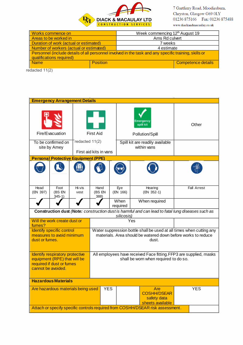
Works commence on Week commencing 12th August 19 Areas to be worked in Arns Rd culvert Duration of work (actual or estimated) 7 weeks Number of workers (actual or estimated) 4 estimate Personnel (include details of all personnel involved in the task and any specific training, skills or qualifications required) Name Position Competence details
Emergency Arrangement Details
Fire/Evacuation
First Aid
Pollution/Spill
Other
To be confirmed on site by Amey
First aid kits in vans
Spill kit are readily available within vans
Personal Protective Equipment (PPE)
Head
(EN 397)
Foot
(BS EN
345-1)
Hi-vis
vest
Hand
(BS EN
388)
Eye
(EN 166)
Hearing
(EN 352-1)
Fall Arrest
When
required When required
Construction dust (Note: construction dust is harmful and can lead to fatal lung diseases such as silicosis)
Will the work create dust or fumes?
Yes
Identify specific control measures to avoid minimum dust or fumes.
Water suppression bottle shall be used at all times when cutting any materials. Area should be watered down before works to reduce
dust.
Identify respiratory protective equipment (RPE) that will be required if dust or fumes cannot be avoided.
All employees have received Face fitting.FFP3 are supplied, masks shall be worn when required to do so.
Hazardous Materials
Are hazardous materials being used YES Are COSHH/DSEAR
safety data sheets available
YES
Attach or specify specific controls required from COSHH/DSEAR risk assessment.
redacted 11(2)
redacted 11(2)
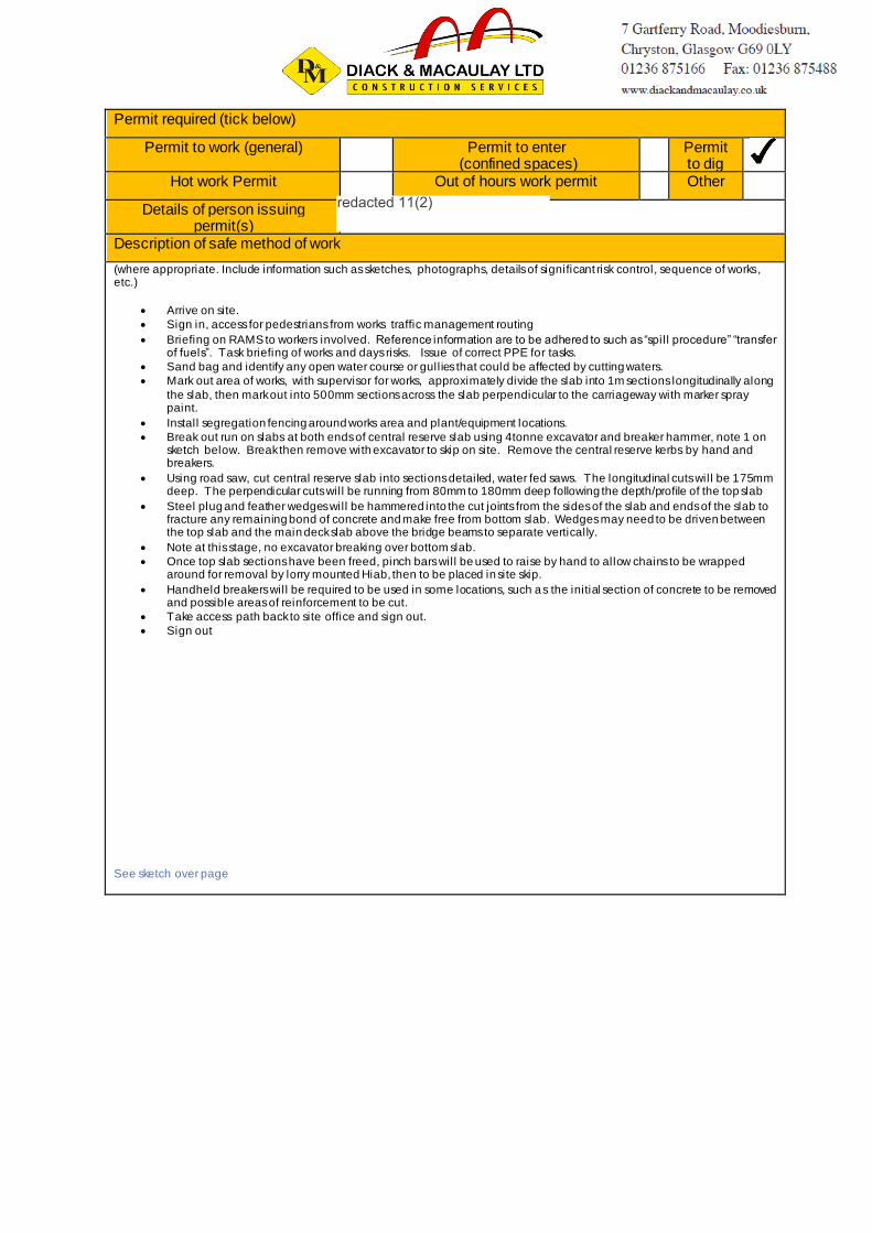
Permit required (tick below)
Permit to work (general) Permit to enter (confined spaces)
Permit to dig
Hot work Permit Out of hours work permit Other
Details of person issuing permit(s)
Description of safe method of work
(where appropriate. Include information such as sketches, photographs, details of significant risk control, sequence of works, etc.)
• Arrive on site.
• Sign in, access for pedestrians from works traffic management routing
• Briefing on RAMS to workers involved. Reference information are to be adhered to such as “spil l procedure” “transfer of fuels”. Task briefing of works and days risks. Issue of correct PPE for tasks.
• Sand bag and identify any open water course or gullies that could be affected by cutting waters.
• Mark out area of works, with supervisor for works, approximately divide the slab into 1m sections longitudinally along
the slab, then mark out into 500mm sections across the slab perpendicular to the carriageway with marker spray paint.
• Install segregation fencing around works area and plant/equipment locations.
• Break out run on slabs at both ends of central reserve slab using 4tonne excavator and breaker hammer, note 1 on sketch below. Break then remove with excavator to skip on site. Remove the central reserve kerbs by hand and breakers.
• Using road saw, cut central reserve slab into sections detailed, water fed saws. The longitudinal cuts will be 175mm deep. The perpendicular cuts will be running from 80mm to 180mm deep following the depth/profile of the top slab
• Steel plug and feather wedges will be hammered into the cut joints from the sides of the slab and ends of the slab to fracture any remaining bond of concrete and make free from bottom slab. Wedges may need to be driven between the top slab and the main deck slab above the bridge beams to separate vertically.
• Note at this stage, no excavator breaking over bottom slab.
• Once top slab sections have been freed, pinch bars will be used to raise by hand to allow chains to be wrapped around for removal by lorry mounted Hiab, then to be placed in site skip.
• Handheld breakers will be required to be used in some locations, such as the initial section of concrete to be removed and possible areas of reinforcement to be cut.
• Take access path back to site office and sign out.
• Sign out
See sketch over page
redacted 11(2)

MATERIALS TO BE USED
• Sand bagging
• Disposal of exisitng Concrete
redacted 11(2)

Tools, plant and equipment to be used
Type Details of inspection/Test Certificates Confirm on site 450mm floor/road saws Jack hammers Hilti breakers
Hand tools
Generators Sthil Saw Water suppression bottle Spill kits Spill trays Briefing Register A copy of this briefing register must be attached to the method statement, together with other relevant information (such as the associated risk assessments, permits or COSHH assessments). Supervisor in charge of work I confirm that I have read and understand the requirements of this method statement and associated risk assessments (as highlighted on first page) and have communicated them to operatives under my control and to others who may be affected by its requirements. Note: it is important that you test the operatives’ understanding and confirm that they have read and understood the method statement and risk assessments. Name
Position
Signature
Date
Operatives/Workforce carrying out works
I understand and will agree to adhere to the contents of this method statement and the associated risk assessments (as highlighted by the supervisor). I have attended a site induction/briefing that explained the general site rules and necessary site-specific arrangements. Note: if you have any doubt about information given or contained in this method statement, ask for clarification. Name Position Signature Date
redacted 11(2)
redacted 11(2)
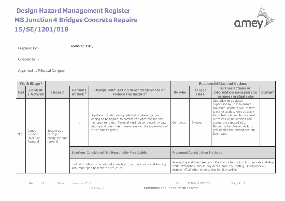
Design Hazard Management Register
M8 Junction 4 Bridges Concrete Repairs
15/SE/1201/018
Rev: 01 Date: November 2017 Ref: STRU-HS-FO-003 Page 1 of 9
© Amey plc UNCONTROLLED IF COPIED OR PRINTED
Prepared by:-
Checked by :-
Approved by Principal Designer
Work Stage 1 Responsibilities and Actions
Ref Element
/ Activity Hazard
Persons at Risk 2
Design Team Action taken to eliminate or reduce the hazard 3
By who Target Date
Further actions or Information necessary to
manage residual risks Status4
9.1
Central Reserve
Over Slab Removal
Bottom slab damaged
during top slab removal
1
Depths of top slab clearly labelled on drawings. No
loading to be applied to bottom slab once the top slab has been removed. Removal must be completed by saw
cutting and using hand breakers under the supervision of the on-site Engineer.
Contractor Ongoing
Operation to be closely supervised by DSR to ensure
maximum depth of slab removal
is not exceeded. Area adjacent to central reserved to be coned
off to ensure no vehicles can access the exposed slab.
Netting to be checked daily to ensure that the netting has not
been torn.
Solutions Considered Not Reasonably Practicable Presumed Construction Methods
Hydrodemoliltion – considered inpractical due to accuracy and keeping
local road open beneath the structure.
Sawcutting and handbreakers. Contractor to monitor bottom slab and stop
work immediately should any debris enter the netting. Contractor on monitor HAVS when undertaking hand breaking.
redacted 11(2)
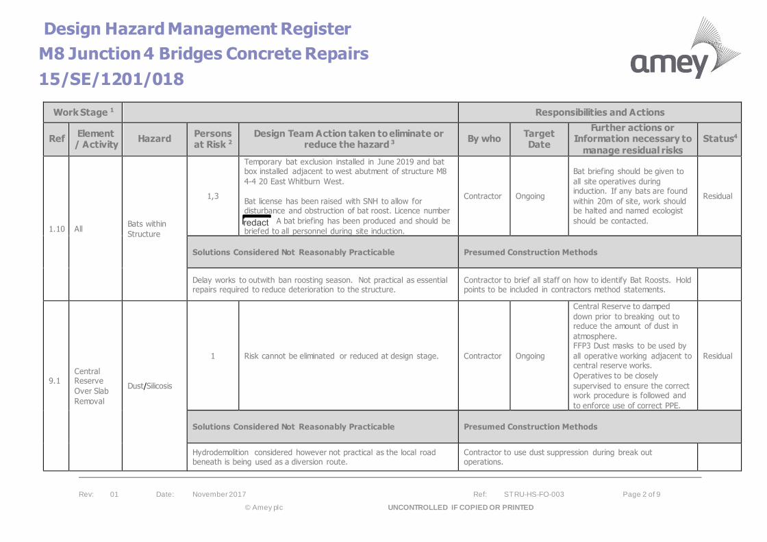
Design Hazard Management Register
M8 Junction 4 Bridges Concrete Repairs
15/SE/1201/018
Rev: 01 Date: November 2017 Ref: STRU-HS-FO-003 Page 2 of 9
© Amey plc UNCONTROLLED IF COPIED OR PRINTED
Work Stage 1 Responsibilities and Actions
Ref Element
/ Activity Hazard
Persons at Risk 2
Design Team Action taken to eliminate or reduce the hazard 3
By who Target Date
Further actions or Information necessary to
manage residual risks
Status4
1.10 All Bats within
Structure
1,3
Temporary bat exclusion installed in June 2019 and bat box installed adjacent to west abutment of structure M8
4-4 20 East Whitburn West.
Bat license has been raised with SNH to allow for disturbance and obstruction of bat roost. Licence number
A bat briefing has been produced and should be
briefed to all personnel during site induction.
Contractor Ongoing
Bat briefing should be given to
all site operatives during induction. If any bats are found
within 20m of site, work should be halted and named ecologist
should be contacted.
Residual
Solutions Considered Not Reasonably Practicable Presumed Construction Methods
Delay works to outwith ban roosting season. Not practical as essential repairs required to reduce deterioration to the structure.
Contractor to brief all staff on how to identify Bat Roosts. Hold points to be included in contractors method statements.
9.1
Central Reserve
Over Slab
Removal
Dust/Silicosis
1 Risk cannot be eliminated or reduced at design stage. Contractor Ongoing
Central Reserve to damped
down prior to breaking out to reduce the amount of dust in
atmosphere. FFP3 Dust masks to be used by
all operative working adjacent to central reserve works.
Operatives to be closely
supervised to ensure the correct work procedure is followed and
to enforce use of correct PPE.
Residual
Solutions Considered Not Reasonably Practicable Presumed Construction Methods
Hydrodemolition considered however not practical as the local road beneath is being used as a diversion route.
Contractor to use dust suppression during break out operations.
redacted 11(2)
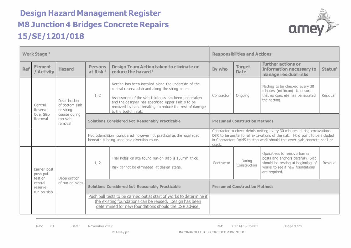
Design Hazard Management Register
M8 Junction 4 Bridges Concrete Repairs
15/SE/1201/018
Rev: 01 Date: November 2017 Ref: STRU-HS-FO-003 Page 3 of 9
© Amey plc UNCONTROLLED IF COPIED OR PRINTED
Work Stage 1 Responsibilities and Actions
Ref Element / Activity
Hazard Persons at Risk 2
Design Team Action taken to eliminate or reduce the hazard 3
By who Target Date
Further actions or Information necessary to
manage residual risks
Status4
Central
Reserve
Over Slab Removal
Delamination of bottom slab
or string
course during top slab
removal
1, 2
Netting has been installed along the underside of the
central reserve slab and along the string course.
Assessment of the slab thickness has been undertaken and the designer has specificed upper slab is to be
removed by hand breaking to reduce the resk of damage
to the bottom slab.
Contractor Ongoing
Netting to be checked every 30 minutes (minimum) to ensure
that no concrete has penetrated
the netting.
Residual
Solutions Considered Not Reasonably Practicable Presumed Construction Methods
Hydrodemolition considered however not practical as the local road beneath is being used as a diversion route.
Contractor to check debris netting every 30 minutes during excavations.
DSR to be onsite for all excavations of the slab. Hold point to be included in Contractors RAMS to stop work should the lower slab concrete spall or
crack.
Barrier post
push-pull test on
central reserve
run-on slab
Deterioration
of run-on slabs
1, 2
Trial holes on site found run-on slab is 150mm thick.
Risk cannot be eliminated at design stage.
Contractor During Construction
Operatives to remove barrier
posts and anchors carefully. Slab
should be testing at beginning of works to see if new foundations
are required.
Residual
Solutions Considered Not Reasonably Practicable Presumed Construction Methods
Push pull tests to be carried out at start of works to determine if the existing foundations can be reused. Design has been determined for new foundations should the DSR advise.
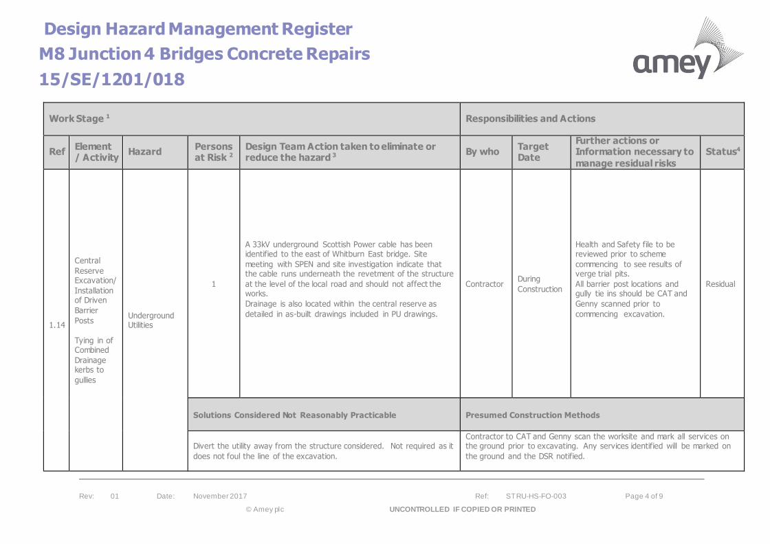
Design Hazard Management Register
M8 Junction 4 Bridges Concrete Repairs
15/SE/1201/018
Rev: 01 Date: November 2017 Ref: STRU-HS-FO-003 Page 4 of 9
© Amey plc UNCONTROLLED IF COPIED OR PRINTED
Work Stage 1 Responsibilities and Actions
Ref Element / Activity
Hazard Persons at Risk 2
Design Team Action taken to eliminate or reduce the hazard 3
By who Target Date
Further actions or Information necessary to
manage residual risks
Status4
1.14
Central
Reserve Excavation/
Installation of Driven
Barrier
Posts
Tying in of Combined
Drainage kerbs to
gullies
Underground Utilities
1
A 33kV underground Scottish Power cable has been identified to the east of Whitburn East bridge. Site
meeting with SPEN and site investigation indicate that the cable runs underneath the revetment of the structure
at the level of the local road and should not affect the works.
Drainage is also located within the central reserve as
detailed in as-built drawings included in PU drawings.
Contractor During
Construction
Health and Safety file to be reviewed prior to scheme
commencing to see results of verge trial pits.
All barrier post locations and gully tie ins should be CAT and
Genny scanned prior to
commencing excavation.
Residual
Solutions Considered Not Reasonably Practicable Presumed Construction Methods
Divert the utility away from the structure considered. Not required as it
does not foul the line of the excavation.
Contractor to CAT and Genny scan the worksite and mark all services on the ground prior to excavating. Any services identified will be marked on
the ground and the DSR notified.

Design Hazard Management Register
M8 Junction 4 Bridges Concrete Repairs
15/SE/1201/018
Rev: 01 Date: November 2017 Ref: STRU-HS-FO-003 Page 5 of 9
© Amey plc UNCONTROLLED IF COPIED OR PRINTED
Work Stage 1 Responsibilities and Actions
Ref Element / Activity
Hazard Persons at Risk 2
Design Team Action taken to eliminate or reduce the hazard 3
By who Target Date
Further actions or Information necessary to
manage residual risks
Status4
7.1 All
Live traffic
lane next to
working area.
1, 2, 3
The following TM has been designed with the Principal
Designer:
Phase 1:
Traffic Management will see the closure of lane 1 and 2 in the eastbound carriageway and a closure of lane 2 in
the westbound carriageway. A temporary safety barrier will be installed adjacent to the lane 1 edge line
eastbound and along the centre line westbound. This is
to protect the bottom central reserve slab once exposed. Eastbound traffic will be diverted onto the hard shoulder
and down and up the slip roads. Westbound traffic will be diverted down and up the slip road and onto lane 1. The
Traffic Management will be in operation 24 hours a day and will have a reduced speed limit of 40mph.
Phase 2: This will see a full closure of the eastbound carriageway
between the slip roads at M8 J4 for 3 weeks. Eastbound lane 1 traffic will be pushed down and up the slip road
while lane 2 traffic will contraflow onto lane 2 of the
westbound carriageway. Westbound lane 1 will be pushed onto the hard shoulder and down and up the slip
roads while lane 2 traffic will travel in lane 1. The traffic management will then be changed for a
westbound closure for 3 weeks. Westbound lane 1 traffic will be pushed down and up the slip road while lane 2
traffic will contraflow onto lane 2 of the eastbound
carriageway. Eastbound lane 1 will be pushed onto the hard shoulder and down and up the slip roads while lane
2 traffic will travel in lane 1.
Contractor Before
construction
Traffic management will be compliant with Traffic Sign
Manual Chapter 8. A temporary safety barrier will also be
installed during the work to protect the workforce. Setting
up of TM will be carried out
during off-peak hours.
Residual
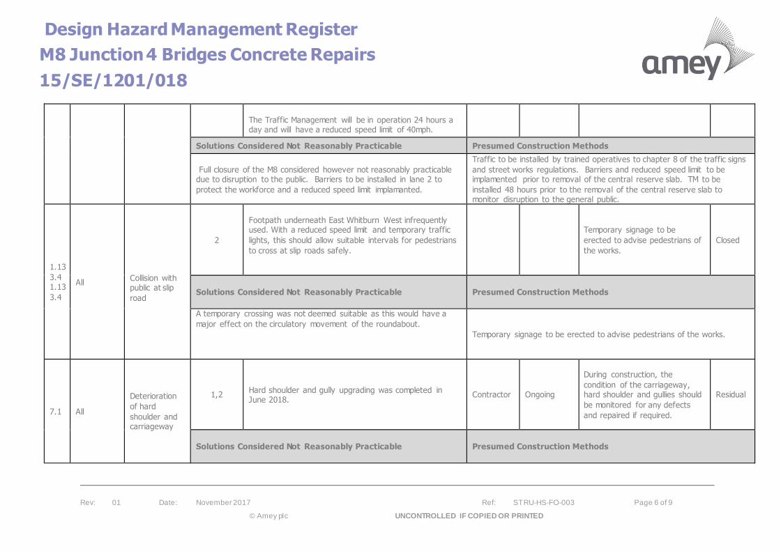
Design Hazard Management Register
M8 Junction 4 Bridges Concrete Repairs
15/SE/1201/018
Rev: 01 Date: November 2017 Ref: STRU-HS-FO-003 Page 6 of 9
© Amey plc UNCONTROLLED IF COPIED OR PRINTED
The Traffic Management will be in operation 24 hours a day and will have a reduced speed limit of 40mph.
Solutions Considered Not Reasonably Practicable Presumed Construction Methods
Full closure of the M8 considered however not reasonably practicable due to disruption to the public. Barriers to be installed in lane 2 to
protect the workforce and a reduced speed limit implamanted.
Traffic to be installed by trained operatives to chapter 8 of the traffic signs
and street works regulations. Barriers and reduced speed limit to be implamented prior to removal of the central reserve slab. TM to be
installed 48 hours prior to the removal of the central reserve slab to monitor disruption to the general public.
1.13
3.4 1.13
3.4
All
Collision with public at slip
road
2
Footpath underneath East Whitburn West infrequently used. With a reduced speed limit and temporary traffic
lights, this should allow suitable intervals for pedestrians
to cross at slip roads safely.
Temporary signage to be
erected to advise pedestrians of
the works.
Closed
Solutions Considered Not Reasonably Practicable Presumed Construction Methods
A temporary crossing was not deemed suitable as this would have a
major effect on the circulatory movement of the roundabout.
Temporary signage to be erected to advise pedestrians of the works.
7.1 All
Deterioration
of hard
shoulder and carriageway
1,2 Hard shoulder and gully upgrading was completed in June 2018.
Contractor Ongoing
During construction, the
condition of the carriageway, hard shoulder and gullies should
be monitored for any defects
and repaired if required.
Residual
Solutions Considered Not Reasonably Practicable Presumed Construction Methods
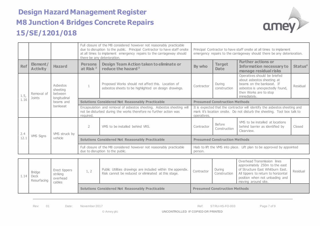
Design Hazard Management Register
M8 Junction 4 Bridges Concrete Repairs
15/SE/1201/018
Rev: 01 Date: November 2017 Ref: STRU-HS-FO-003 Page 7 of 9
© Amey plc UNCONTROLLED IF COPIED OR PRINTED
Full closure of the M8 considered however not reasonably practicable
due to disruption to the public. Principal Contractor to have staff onsite at all times to implament emergency repairs to the carriageway should
there be any deterioration.
Principal Contractor to have staff onsite at all times to implament emergency repairs to the carriageway should there be any deterioration.
Ref Element/ Activity
Hazard Persons at Risk 2
Design Team Action taken to eliminate or reduce the hazard 3
By who Target Date
Further actions or Information necessary to manage residual risks
Status4
1.5, 1.16
Removal of
Joints
Asbestos
sheeting between
longitudinal beams and
bankseat
1 Proposed Works should not affect this. Location of
asbestos sheets to be highlighted on design drawings. Contractor
During
construction
Operatives should be briefed
about asbestos sheeting at beams on the bankseat. If
asbestos is unexpectedly found,
then Works are to stop immediately.
Residual
Solutions Considered Not Reasonably Practicable Presumed Construction Methods
Encapsulation and removal of asbestos sheeting. Asbestos sheeting will
not be disturbed during the works therefore no further action was required.
It is expected that the contractor will identify the asbestos sheeting and
mark it’s location onsite. Do not disturb the sheeting. Tool box talk to operatives.
2.4
12.1 VMS Signs
VMS struck by
vehicle
2 VMS to be installed behind VRS. Contractor Before
Construction
VMS to be installed at locations
behind barrier as identified by
Clearview.
Closed
Solutions Considered Not Reasonably Practicable Presumed Construction Methods
Full closure of the M8 considered however not reasonably practicable due to disruption to the public.
Hiab to lift the VMS into place. Lift plan to be approved by appointed person.
1.14 Bridge Deck
Resurfacing
Erect tippers striking
overhead cables
1, 2 Public Utilities drawings are included within the appendix. Risk cannot be reduced or eliminated at this stage.
Contractor During Construction
Overhead Transmission lines approximately 250m to the east
of Structure East Whitburn East. All tippers to return to horizontal
position when not unloading and moving around site.
Residual
Solutions Considered Not Reasonably Practicable Presumed Construction Methods
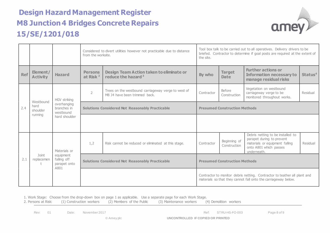
Design Hazard Management Register
M8 Junction 4 Bridges Concrete Repairs
15/SE/1201/018
Rev: 01 Date: November 2017 Ref: STRU-HS-FO-003 Page 8 of 9
© Amey plc UNCONTROLLED IF COPIED OR PRINTED
Considered to divert utilities however not practicable due to distance from the worksite.
Tool box talk to be carried out to all operatives. Delivery drivers to be
briefed. Contractor to determine if goal posts are required at the extent of the site.
Ref Element/ Activity
Hazard Persons at Risk 2
Design Team Action taken to eliminate or reduce the hazard 3
By who Target Date
Further actions or Information necessary to manage residual risks
Status4
2.4
Westbound hard
shoulder
running
HGV striking
overhanging branches in
westbound hard shoulder
2 Trees on the westbound carriageway verge to west of
M8 J4 have been trimmed back. Contractor
Before
Construction
Vegetation on westbound carriageway verge to be
monitored throughout works.
Residual
Solutions Considered Not Reasonably Practicable Presumed Construction Methods
2.1 Joint
replacemen
t
Materials or
equipment falling off
parapet onto
A801
1,2 Risk cannot be reduced or eliminated at this stage. Contractor Beginning of
Construction
Debris netting to be installed to parapet during to prevent
materials or equipment falling onto A801 which passes
underneath.
Residual
Solutions Considered Not Reasonably Practicable Presumed Construction Methods
Contractor to monitor debris netting. Contractor to teather all plant and materials so that they cannot fall onto the carriageway below.
1. Work Stage: Choose from the drop-down box on page 1 as applicable. Use a separate page for each Work Stage.
2. Persons at Risk: (1) Construction workers (2) Members of the Public (3) Maintenance workers (4) Demolition workers

Design Hazard Management Register
M8 Junction 4 Bridges Concrete Repairs
15/SE/1201/018
Rev: 01 Date: November 2017 Ref: STRU-HS-FO-003 Page 9 of 9
© Amey plc UNCONTROLLED IF COPIED OR PRINTED
3. Design Team Action taken to eliminate or reduce the hazard. State where the information on the measures taken to reduce the hazard is contained (i.e. PCI, Specification, etc.). Where no measures have been taken, state “None”
4. Status Open, Closed or Residual