Embed Size (px)
Citation preview
Construction of the Iowa Highway 60 Precast Prestressed Concrete Pavement Bridge Approach Slab Demonstration Project
Final Report July 2007 Sponsored by Iowa Highway Research Board (IHRB Project HR-1085) Iowa Department of Transportation Federal Highway Administration

Disclaimer Notice The contents of this report reflect the views of the authors, who are responsible for the facts and the accuracy of the information presented herein. The opinions, findings and conclusions expressed in this publication are those of the authors and not necessarily those of the sponsors. The sponsors assume no liability for the contents or use of the information contained in this document. This report does not constitute a standard, specification, or regulation. The sponsors do not endorse products or manufacturers. Trademarks or manufacturers’ names appear in this report only because they are considered essential to the objective of the document.

1. Report No 2. Government Accession No. 3. Recipient's Catalog No.
4. Title and Subtitle 5. Report Date July 2007 6. Performing Organization Code 7. Authors(s)
8. Performing Organization Report No. 9
1
1 1
1 1
F
IHRB Project HR-1085
Construction of the Iowa Highway 60 Precast Prestressed Concrete Pavement Bridge Approach Slab Demonstration Project
David K. Merritt, Alberto J. Miron, Richard B. Rogers, Robert Otto Rasmussen
. Performing Organization Name and Address 10. Work Unit No. (TRAIS) 11. Contract or Grant No.
The Transtec Group, Inc.6111 Balcones Drive Austin, Texas 78731
13. Type of Report and Period Covered
Final Report 2. Sponsoring Agency Name and Address 14. Sponsoring Agency Code
5. Supplementary Notes
6. Abstract
7. Key Words 18. Distribution Statement
9. Security Classif. (of this report) 20. Security Classif. (of this page) 21. No. of Pages 22. Price
98
orm DOT F 1700.7 (8-72) Reproduction of completed page authorized (art. 5/94)
U.S. Department of Transportation Iowa Highway Research BoardFederal Highway Administration Iowa Department of Transportation 400 7th Street SW, HIPT-20 800 Lincoln Way Washington, DC 20590 Ames, IA 50010
Reconstruction of bridge approach slabs which have failed due to a loss of support from embankment fill consolidation or erosion can be particularly challenging in urban areas where lane closures must be minimized. Precast prestressed concrete pavement is a potential solution for rapid bridge approach slab reconstruction which uses prefabricated pavement panels that can be installed and opened to traffic quickly. To evaluate this solution, the Iowa Department of Transportation constructed a precast prestressed approach slab demonstration project on Highway 60 near Sheldon, Iowa in August/September 2006. Two approach slabs at either end of a new bridge were constructed using precast prestressed concrete panels.
This report documents the successful development, design, and construction of the precast prestressed concrete bridge approach slabs on Highway 60. The report discusses the challenges and issues that were faced during the project and presents recommendations for future implementation of this innovative construction technique.
No restrictions. precast pavement, precast prestressed concrete pavement, bridge approach, prestressed pavement, rapid construction
UnclassifiedUnclassified
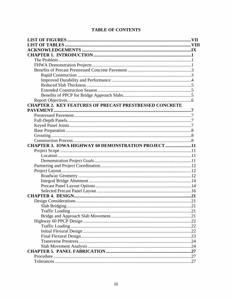
TABLE OF CONTENTS LIST OF FIGURES .............................................................................................................VII LIST OF TABLES ...............................................................................................................VIII ACKNOWLEDGEMENTS ................................................................................................IX CHAPTER 1. INTRODUCTION......................................................................................1
The Problem.....................................................................................................................1 FHWA Demonstration Projects .......................................................................................1 Benefits of Precast Prestressed Concrete Pavement ........................................................3
Rapid Construction ....................................................................................................3 Improved Durability and Performance ......................................................................4 Reduced Slab Thickness ............................................................................................5 Extended Construction Season ..................................................................................5 Benefits of PPCP for Bridge Approach Slabs............................................................5
Report Objectives.............................................................................................................6 CHAPTER 2. KEY FEATURES OF PRECAST PRESTRESSED CONCRETE PAVEMENT.........................................................................................................................7
Prestressed Pavement.......................................................................................................7 Full-Depth Panels.............................................................................................................7 Keyed Panel Joints...........................................................................................................7 Base Preparation ..............................................................................................................8 Grouting ...........................................................................................................................8 Construction Process........................................................................................................8
CHAPTER 3. IOWA HIGHWAY 60 DEMONSTRATION PROJECT.......................11 Project Scope ...................................................................................................................11
Location .....................................................................................................................11 Demonstration Project Goals .....................................................................................11
Partnering and Project Coordination................................................................................12 Project Layout..................................................................................................................12
Roadway Geometry ...................................................................................................12 Integral Bridge Abutment ..........................................................................................14 Precast Panel Layout Options ....................................................................................14 Selected Precast Panel Layout ...................................................................................16
CHAPTER 4. DESIGN.......................................................................................................21 Design Considerations .....................................................................................................21
Slab Bridging .............................................................................................................21 Traffic Loading ..........................................................................................................21 Bridge and Approach Slab Movement.......................................................................21
Highway 60 PPCP Design ...............................................................................................22 Traffic Loading ..........................................................................................................22 Initial Flexural Design ...............................................................................................22 Final Flexural Design.................................................................................................23 Transverse Prestress...................................................................................................24 Slab Movement Analysis ...........................................................................................24
CHAPTER 5. PANEL FABRICATION...........................................................................27 Procedure .........................................................................................................................27 Tolerances ........................................................................................................................27
iii
Panel Details ....................................................................................................................27 Keyways.....................................................................................................................27 Post-Tensioning .........................................................................................................29 Anchor Sleeves ..........................................................................................................30 Expansion Joint..........................................................................................................30 Reinforcement............................................................................................................30 Lifting Anchors..........................................................................................................31
Mixture Design ................................................................................................................31 Finishing and Curing .......................................................................................................32 Handling and Storage.......................................................................................................33 Trial Assembly.................................................................................................................33 Panel Repairs ...................................................................................................................34 Fabrication Issues and Challenges ...................................................................................37
Post-Tensioning Ducts ...............................................................................................37 Pocket Reinforcement................................................................................................37 Formwork...................................................................................................................37 Panel Damage ............................................................................................................38
CHAPTER 6. APPROACH SLAB CONSTRUCTION ..................................................39 Pre-Construction Meetings ..............................................................................................39 Base Preparation ..............................................................................................................39 Panel Installation..............................................................................................................40
Procedure ...................................................................................................................40 Joint Epoxy ................................................................................................................41 Temporary Post-Tensioning ......................................................................................41
Post-Tensioning ...............................................................................................................42 Grouting ...........................................................................................................................44
Tendon Grouting........................................................................................................44 Underslab Grouting....................................................................................................45
Finishing and Tie-in.........................................................................................................46 Longitudinal Joint ......................................................................................................46 Pocket Filling .............................................................................................................47 Bridge Abutment Anchor...........................................................................................47 Expansion Joint..........................................................................................................47 Diamond Grinding .....................................................................................................48
Construction Issues and Challenges.................................................................................49 Panel Placement .........................................................................................................49 Post-Tensioning .........................................................................................................51 Grouting .....................................................................................................................51
Instrumentation and Monitoring ......................................................................................52 Bridge Instrumentation ..............................................................................................52 Approach Slab Instrumentation .................................................................................53
Showcasing Workshop.....................................................................................................53 CHAPTER 7. PROJECT EVALUATION AND RECOMMENDATIONS FOR FUTURE PROJECTS...........................................................................................................................55
Project Layout..................................................................................................................55 Design ..............................................................................................................................56
Design Procedures .....................................................................................................56
iv

Design Details............................................................................................................56 Panel Fabrication .............................................................................................................57 Construction.....................................................................................................................58
Base Preparation ........................................................................................................58 Panel Installation........................................................................................................59 Post-tensioning...........................................................................................................59 Grouting .....................................................................................................................60
Post-Construction Evaluation ..........................................................................................61 Project Cost......................................................................................................................61
CHAPTER 8. SUMMARY AND RECOMMENDATIONS ...........................................63 Summary ..........................................................................................................................63 Recommendations for Future Implementation ................................................................63
REFERENCES.....................................................................................................................65 APPENDIX...........................................................................................................................67
v


LIST OF FIGURES
Figure 1. Flowchart for the overall PPCP construction process. .................................................... 9 Figure 2. Location of the Iowa precast pavement demonstration project..................................... 11 Figure 3. Situation Plan for the Highway 60 bridge and precast approach slabs. ....................... 13 Figure 4. Schematic layout of full-width panels with variable thickness. ................................... 15 Figure 5. Schematic layout of partial width panels with uniform thickness................................ 16 Figure 6. Selected precast panel and post-tensioning tendon layout. .......................................... 17 Figure 7. Selected precast panel layout........................................................................................ 18 Figure 8. Longitudinal joint at the centerline of the approach slab. ............................................ 18 Figure 9. Approach slab Abutment Panels. ................................................................................. 19 Figure 10. Approach slab Base Panels......................................................................................... 19 Figure 11. Approach slab Joint Panels......................................................................................... 20 Figure 12. Transverse keyway dimensions for the precast panels .............................................. 28 Figure 13. Keyway dimensions for the longitudinal joint. .......................................................... 29 Figure 14. Post-tensioning tendon gasket detail. ......................................................................... 30 Figure 15. Placement of concrete for an abutment panel............................................................. 31 Figure 16. Application of the light broom texture to the panel surface....................................... 32 Figure 17. Curing tent being lowered to cover a precast panel after casting............................... 33 Figure 18. Precast panels stored at the fabrication plant. ............................................................ 34 Figure 19. Trial assembly of precast panels at the fabrication plant. .......................................... 34 Figure 20. Damaged panel corner after trial assembly. ............................................................... 35 Figure 21. Damaged keyway after trial assembly........................................................................ 36 Figure 22. Battered keyway after removal from forms................................................................ 36 Figure 23. Keyway after completion of grinding......................................................................... 37 Figure 24. Grading and compaction of the aggregate base material............................................ 39 Figure 25. Installation of Panel 1A at the south bridge abutment. .............................................. 40 Figure 26. Finished approach slab prior to final post-tensioning. ............................................... 41 Figure 27. Application of joint epoxy during panel installation.................................................. 42 Figure 28. Temporary post-tensioning used to pull panels together............................................ 42 Figure 29. Inserting the longitudinal strands into the approach slab. .......................................... 43 Figure 30. Inserting the transverse strands into the approach slab. ............................................. 44 Figure 31. Grouting of the post-tensioning tendons. ................................................................... 45 Figure 32. Rod and level were used to check for slab lifting during the underslab grouting operation.. ..................................................................................................................................... 46 Figure 33. Filling of the longitudinal joint................................................................................... 47 Figure 34. Abutment anchor detail for PPCP approach slabs...................................................... 48 Figure 35. Dowels for the EF expansion joint prior to installing them in the precast panels...... 48 Figure 36. Diamond grinding the south approach slab. ............................................................... 49 Figure 37. Joint between south approach slab and bridge abutment. .......................................... 50 Figure 38. Minor joint spall which occurred during panel installation........................................ 51 Figure 39. Slight misalignment of transverse post-tensioning ducts at the longitudinal joint..... 52 Figure 40. Vibrating wire strain gage mounted in the precast panel during fabrication. ............ 53 Figure 41. Presentations were provided by those involved in the Highway 60 project............... 54 Figure 42. Site visit during installation of the precast approach slab. ......................................... 54 Figure 43. Finished north approach slab prior to opening to traffic. ........................................... 64
vii

LIST OF TABLES
Table 1. Factored design moments for Highway 60 approach slab (15 ft simple span)............... 22 Table 2. Flexural capacity of various prestressing configurations. .............................................. 23 Table 3. Predicted movements at the ends of the approach slabs. ............................................... 25 Table 4. Table of panel tolerances from the project plans........................................................... 28
viii

ACKNOWLEDGEMENTS
The researchers would like to acknowledge the Federal Highway Administration and Iowa Highway Research Board for sponsoring this project. The authors would also like to acknowledge all of the individuals involved in making this a successful project from the Office of Bridges and Structures, Research and Technology Bureau, District 1 and District 3 Offices, FHWA Office of Pavement Technology, FHWA Iowa Division Office, and Bridge Engineering Center at Iowa State University.
ix


EXECUTIVE SUMMARY
The “bump at the end of the bridge” caused by bridge approach slab settlement is an ongoing problem for Iowa and many other state highway agencies. The bump not only degrades the ride quality of a roadway, but also presents a safety issue for drivers and increases impact loads on bridges. Approach slab settlement is generally caused by a loss of support due to consolidation or erosion of the underlying embankment fill, and can be accompanied by failure of the paving notch. While problems with the embankment fill material and paving notch must ultimately be resolved through improved construction practices, a separate but equally important issue is how to reconstruct bridge approach slabs that have already failed due to settlement. This is particularly challenging in urban areas where lane closures must be minimized to reduce the impact of reconstruction on the traveling public. The solution must not only be something that will permit the approach slab to be reconstructed quickly (during overnight or weekend closures), but something that will provide good long-term performance even if future loss of support occurs. The primary objective of this research was to evaluate the viability of using precast prestressed concrete panels for bridge approach slab reconstruction. Ultimately, this construction process will be utilized for bridge approach slabs in urban areas where lane closures for reconstruction must be minimized. A secondary objective was to evaluate and develop standard details for precast prestressed concrete bridge approach slabs that can be adapted to virtually any approach slab configuration. The demonstration project was constructed on the northbound lanes of a new bridge over the Floyd River on the realignment of Highway 60 just east of Sheldon, Iowa. Precast prestressed concrete approach slabs were constructed at either end of the bridge. The layout for the precast panels was selected such that it could be adapted to various approach slab configurations of different thicknesses, widths, lengths, and skew angles The precast panels were post-tensioned in both directions after installation on site. Post-tensioning will not only improve the performance of the approach slab by keeping it in compression to minimize or even eliminate cracking, but also gives the approach slab the ability to act as a “slab bridge,” spanning over voids that may form beneath it over time due to the mechanisms mentioned above. Post-tensioning also allows for a longer section of continuous pavement between joints, permitting the expansion joint to be moved as far away from the abutment as feasible in order to minimize the risk of water infiltration into the embankment fill at the abutment. The precast panels were fabricated in summer 2006 and installed over a two day period (for each approach slab) in August/September 2006. In general, each panel was installed in approximately 15-30 minutes. This installation rate will likely improve at contractors become more familiar with the construction technique. While this project was constructed on a new bridge and the roadway was completely closed to traffic during construction, the intent was to evaluate the overall process and project details. The viability of this construction technique was clearly demonstrated, and rapid reconstruction of existing approach slabs under stringent time constraints will be the next step.
xi

CHAPTER 1. INTRODUCTION
THE PROBLEM
The “bump at the end of the bridge,” caused by bridge approach slab settlement, is an ongoing problem for many state highway agencies. The bump not only degrades the ride quality of a roadway, but also presents a safety issue for drivers and increases impact loads on bridges. Approach slab settlement is generally caused by a loss of support due to consolidation or erosion of the underlying embankment material and may be accompanied by failure of the paving notch/paving seat at the abutment. While problems with the embankment material can be prevented with improved construction practices, a separate but equally important issue is how to reconstruct bridge approach slabs that have already failed. This is particularly challenging in urban areas where lane closures must be minimized to reduce the impact of reconstruction on the traveling public. The Iowa Department of Transportation (IADOT) is addressing this issue by investigating the use of precast prestressed concrete pavement (PPCP) for expedited bridge approach slab reconstruction. Precast panels are fabricated and stockpiled at a precast plant, then delivered to the jobsite and quickly installed as needed. Precast panels can support traffic immediately after installation, thereby facilitating overnight or weekend construction operations. Prestressing the approach slab benefits performance by keeping the pavement in compression to minimize or even eliminate cracking. Further, prestressing gives the approach slab a “bridging” ability to span voids in the embankment material that may redevelop over time, helping to achieve the ultimate goal of longer lasting pavements. In August 2006, IADOT constructed a PPCP approach slab on a new bridge along Highway 60 near Sheldon, Iowa. This successful project allowed IADOT to evaluate and refine design and construction details for PPCP bridge approach slabs. IADOT is currently planning for a second project in which failed approach slabs at either end of twin bridges will be reconstructed under traffic. In addition to utilizing precast concrete for the approach slab, IADOT will also be evaluating the use of precast concrete for replacement of deteriorated or poorly constructed paving notches on these bridges. The end result will be an innovative method for rapid reconstruction of bridge approach slabs with minimal disruption to the traveling public. FHWA DEMONSTRATION PROJECTS
The Highway 60 PPCP bridge approach slab demonstration project was part of a recent effort by the Federal Highway Administration (FHWA) to evaluate the viability of PPCP construction for a variety of paving applications through a series of demonstration projects throughout the United States. These demonstration projects provide state highway agencies (SHAs) the opportunity to evaluate PPCP for pavement rehabilitation and reconstruction, and also help to familiarize local contractors with the technology. FHWA provides design and construction support for these projects and, if necessary, limited funding for construction.
1

The FHWA demonstration projects stemmed from an initial feasibility study completed in 2000 by the Center for Transportation Research at The University of Texas at Austin.(1) This feasibility study resulted in the development of viable concept for precast prestressed concrete pavement which was subsequently been evaluated through three previous demonstration projects in Texas, California, and Missouri between 2001 and 2006. The PPCP concept was adapted to the constraints of each particular project. The Iowa Demonstration Project, described herein, represents the fourth PPCP demonstration project and a fourth adaptation of the PPCP concept to meet the specific needs of state highway agencies. A summary of the four demonstration projects completed to date is provided below.
Interstate 35 Frontage Road – Georgetown, Texas(2)
Completed in spring 2002, the Interstate 35 frontage road demonstration project, constructed by the Texas Department of Transportation, was the first project to demonstrate the viability of the PPCP concept. While not constructed under traffic and short time windows, the intent of this project was to evaluate the design details and construction procedures for PPCP. Approximately 2,300 ft of precast prestressed concrete pavement was constructed the full width of the frontage road. Both “full-width” and “partial-width” panels were utilized. The full-width panels spanned the entire 36 ft width of the roadway, including two traffic lanes and inside and outside shoulders. The partial-width panels were constructed in two adjacent sections, one 20 ft wide and the other 6 ft wide, to achieve the full 36 ft roadway width. The adjacent sections were tied together with additional transverse post-tensioning. The aspects of PPCP that were demonstrated by this project included: • Overall fabrication and construction feasibility of precast prestressed concrete pavement, • Use of an armored expansion joint cast into the precast panels, • Use of central stressing for precast, post-tensioned pavement panels, • Use of non-match-cast precast panels with interlocking keyways, • Installation of precast panels over a hot-mix asphalt leveling course, • Construction of precast pavement on a vertical curve, and • Lane-by-lane construction of precast pavement using “partial-width” precast panels.
Interstate 10 – El Monte, California(3,4)
The second PPCP demonstration project was constructed by the California Department of Transportation (Caltrans) in April 2004. Precast prestressed concrete pavement was incorporated into a project to widen eastbound Interstate 10 near El Monte, California. A 248 ft-long section of PPCP was installed adjacent to the existing mainlanes, adding 27 ft of traffic lanes and a 10 ft shoulder to the existing pavement. Some of the unique aspects demonstrated by this project included: • Incorporation of a change in pavement cross-slope into the surface of the precast panels, • Nighttime installation of precast panels during a 5-hour construction window, • Installation of precast panels over a lean concrete base, • Use of epoxy-coated strands for longitudinal post-tensioning, • Use of a non-armored, dowelled expansion joint, and • Diamond grinding of the finished surface to achieve pavement smoothness requirements.
2

Interstate 57 – Sikeston, Missouri(5,6,7)
The third PPCP demonstration project was constructed by the Missouri Department of Transportation on Interstate 57 near Sikeston, Missouri in 2005. Precast prestressed concrete pavement was used for the reconstruction of 1,010 ft of mainline pavement on I-57. The full 38 ft pavement width was reconstructed with precast panels, including two main lanes and inside and outside shoulders. A summary of the unique aspects that this project demonstrated includes: • Incorporation of a crowned pavement cross-section into the precast panels, • Post-tensioning from the joint panels as opposed to central stressing, • Use of a “header-type” non-armored expansion joint, • Use of a non-continuous keyways for the panel joints, • Installation of precast panels over a permeable asphalt-treated base, and • Diamond grinding of the finished surface to achieve smoothness requirements.
Highway 60 – Sheldon, Iowa(8)
The most recently completed demonstration project, constructed by the Iowa Department of Transportation on State Highway 60 near Sheldon, Iowa, will be described in more detail in this report. Some of the unique aspects that were demonstrated by this project included: • Use of precast prestressed panels for bridge approach slab construction, • Use of bi-directional post-tensioning, • Lane-by-lane construction (partial-width panels) installed on a crowned pavement section, • Installation of panels over an aggregate base, and • Diamond grinding of the finished surface.
BENEFITS OF PRECAST PRESTRESSED CONCRETE PAVEMENT
While the benefits of precast prestressed concrete pavement have been documented more thoroughly elsewhere,(1,2,3,9) a summary of these benefits is provided below, including specific benefits for bridge approach slabs. Rapid Construction
The primary benefit of PPCP is rapid construction. More accurately stated, PPCP permits faster opening of the pavement to traffic. Precast panels are cast and cured off site, allowing them to reach “opening to traffic” strength prior to being installed on site. The need for rapid construction techniques is perhaps even more critical for bridges (and bridge approach slabs) than pavements. Bridges are critical links within a highway system, and it is often not possible to divert traffic around a bridge during reconstruction without significant inconvenience and cost. This generally requires staged reconstruction, permitting only part of the bridge to be reconstructed at any given time, squeezing traffic into fewer lanes, and often increasing user delays. With proper planning, PPCP will permit rapid reconstruction of bridge approach slabs during non-peak travel times, minimizing lane closures and associated user delays.
3

Reduced User Delay Costs
State highway agencies are continually seeking new techniques for pavement reconstruction and rehabilitation that minimize disruption to the traveling public and the associated user delay costs caused by lane closures. In many urban areas, agencies are often limited to overnight or weekend windows for lane closures. This necessitates solutions which will permit the pavement to be opened to traffic quickly. Because precast concrete panels are fabricated and cured offsite, they can be hauled to the jobsite, installed quickly, and opened to traffic almost immediately after installation. A reduction in user delay costs is where the primary economic benefit of PPCP construction will be realized. Reduced Disruption to Local Businesses
Roadway users are not the only people impacted by pavement construction. Construction of intersections and non-controlled access roadways can also have a significant impact on local businesses by limiting access to these businesses by customers and suppliers. PPCP permits construction to be completed during non-peak business hours, thereby minimizing inconvenience to both customers and local businesses. Improved Safety and Reduced Traffic Control Costs
Rapid construction helps improve safety for both construction workers and vehicle drivers by limiting construction operations and associated lane closures to non-peak travel times. During these limited operations, construction workers are less exposed to traffic and drivers are less exposed to traffic control measures. Also, by eliminating the need to build temporary traffic lanes around the project, and by avoiding lengthy detour routes, traffic control costs can be greatly reduced. Improved Durability and Performance
Savings in user delay costs from expedited construction are only beneficial if the solution for reconstruction is a durable, high-performance solution and not just a temporary “quick fix.” Precast prestressed concrete has provided durable, high-performance solutions for the bridge and commercial building industries for decades, and can do the same for pavement. Precast concrete manufacturing plants have a very high degree of control over the concrete mixture and the production process, helping to ensure a very consistent, high quality final product. Further, by incorporating prestress, many additional performance benefits can be realized. Mixture Properties
The precast concrete manufacturing process offers a great deal of flexibility over the concrete mixtures used for precast products. Mixtures with very low water-cement ratios, various combinations of pozzolans, water-reducing and air-entraining admixtures, permit the product to be tailored for the needs of the paving project. Concrete mixtures are produced in a very consistent manner and hauled only short distances from the batch plant to the forms, helping to minimize problems that can often be encountered with cast-in-place pavement construction. Precast concrete manufacturing also permits the use of lightweight aggregates and hollow-core manufacturing processes to reduce the weight of the precast panels.
4
Curing
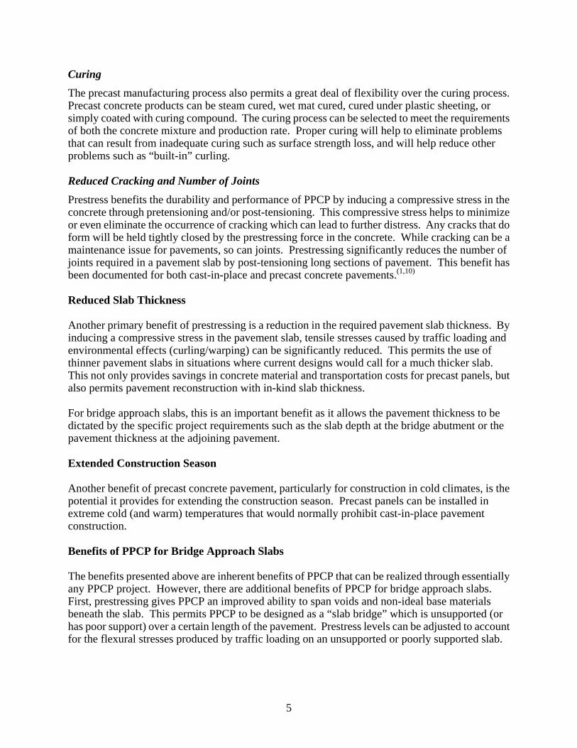
The precast manufacturing process also permits a great deal of flexibility over the curing process. Precast concrete products can be steam cured, wet mat cured, cured under plastic sheeting, or simply coated with curing compound. The curing process can be selected to meet the requirements of both the concrete mixture and production rate. Proper curing will help to eliminate problems that can result from inadequate curing such as surface strength loss, and will help reduce other problems such as “built-in” curling. Reduced Cracking and Number of Joints
Prestress benefits the durability and performance of PPCP by inducing a compressive stress in the concrete through pretensioning and/or post-tensioning. This compressive stress helps to minimize or even eliminate the occurrence of cracking which can lead to further distress. Any cracks that do form will be held tightly closed by the prestressing force in the concrete. While cracking can be a maintenance issue for pavements, so can joints. Prestressing significantly reduces the number of joints required in a pavement slab by post-tensioning long sections of pavement. This benefit has been documented for both cast-in-place and precast concrete pavements.(1,10)
Reduced Slab Thickness
Another primary benefit of prestressing is a reduction in the required pavement slab thickness. By inducing a compressive stress in the pavement slab, tensile stresses caused by traffic loading and environmental effects (curling/warping) can be significantly reduced. This permits the use of thinner pavement slabs in situations where current designs would call for a much thicker slab. This not only provides savings in concrete material and transportation costs for precast panels, but also permits pavement reconstruction with in-kind slab thickness. For bridge approach slabs, this is an important benefit as it allows the pavement thickness to be dictated by the specific project requirements such as the slab depth at the bridge abutment or the pavement thickness at the adjoining pavement. Extended Construction Season
Another benefit of precast concrete pavement, particularly for construction in cold climates, is the potential it provides for extending the construction season. Precast panels can be installed in extreme cold (and warm) temperatures that would normally prohibit cast-in-place pavement construction. Benefits of PPCP for Bridge Approach Slabs
The benefits presented above are inherent benefits of PPCP that can be realized through essentially any PPCP project. However, there are additional benefits of PPCP for bridge approach slabs. First, prestressing gives PPCP an improved ability to span voids and non-ideal base materials beneath the slab. This permits PPCP to be designed as a “slab bridge” which is unsupported (or has poor support) over a certain length of the pavement. Prestress levels can be adjusted to account for the flexural stresses produced by traffic loading on an unsupported or poorly supported slab.
5

For bridge approach slabs, where a loss of support due to erosion or consolidation of the underlying embankment might be anticipated in the future, this is a significant benefit. Another benefit of PPCP for bridge approach slabs is the permissible slab length between expansion joints. By prestressing the approach slab, expansion joints can be moved further away from the abutment where water infiltration into the embankment can cause erosion and consolidation of the embankment material. Prestressing can also be used to permanently tie the approach slab to the bridge abutment, keeping the joint between the abutment and approach slab tightly closed. REPORT OBJECTIVES
The primary objective of this report is to summarize the construction of the precast prestressed concrete pavement demonstration project on Highway 60 near Sheldon, Iowa. This includes the design, fabrication, and panel installation processes for the project. The report also presents recommendations for future PPCP bridge approach slab projects based on lessons learned from this project. The following is a summary of the remaining chapters of this report: Chapter 2 presents the key features of PPCP that were developed through the feasibility study and refined through the course of previous demonstration projects. Chapter 3 presents an overview of the Highway 60 approach slab demonstration project, including the precast panel layout. Chapter 4 presents the design of the Highway 60 project, including the design procedure and design details. Chapter 5 discusses the fabrication of the precast panels for the Highway 60 demonstration project, including issues that should be addressed for future projects. Chapter 6 discusses the construction or installation of the precast pavement on site. This includes base preparation, transportation, panel placement, post-tensioning, grouting, and instrumentation. Chapter 7 presents an evaluation of all aspects of the Highway 60 demonstration project and some considerations for future projects.
6

CHAPTER 2. KEY FEATURES OF PRECAST PRESTRESSED CONCRETE PAVEMENT
The concept for precast prestressed concrete pavement that formed the basis for the Highway 60 demonstration project was developed through the original FHWA feasibility study.(1) While the bridge approach slab application differs somewhat from the original concept in terms of design features, many of the basic aspects of the project are the same. Below is a brief summary of these aspects. PRESTRESSED PAVEMENT
The PPCP concept utilizes prestressing through either a combination of pretensioning and post-tensioning, or just post-tensioning. It is critical that prestress is provided in both directions, as previous experience with cast-in-place prestressed pavements has shown that prestress in only one direction can lead to cracking above the prestressing tendons.(10) The original PPCP concept featured precast panels that were pretensioned in the transverse direction during fabrication and post-tensioned together in the longitudinal direction after installation, generally in 250 ft sections.(2) However, as will be discussed later, bi-directional post-tensioning can also be used, as was done for the Highway 60 demonstration project. Regardless of whether post-tensioning is in one or both directions, the post-tensioning system is a grouted or bonded system. FULL-DEPTH PANELS
Another key aspect of the PPCP concept is the use of full-depth precast panels. Using full-depth panels, the top surface of the precast panels is the riding surface. Although diamond grinding may be required to achieve high-speed facility smoothness requirements, the pavement can generally be opened to traffic prior to diamond grinding. This was successfully demonstrated by the Texas demonstration project which has not been diamond ground after five years in service.(2) Full-depth panels provide an efficient solution as they do not require a hot-mix asphalt or bonded concrete overlay for the final riding surface. Full-depth panels do require careful attention to base preparation, however, to ensure that the panels are set to the proper elevation and are not resting on high points which could cause them to shift. KEYED PANEL JOINTS
Another important feature of the PPCP concept, particularly for full-depth precast panels, is the use of continuous keyways along the edges of the panels. These keyways help to ensure vertical alignment between the panels as they are installed, minimizing the amount of grinding and surface correction required for the final driving surface. It is important to note that the precast panels are not match-cast. Match-casting is a more time consuming and costly operation, and may only be viable for small projects. The dimensions and tolerances for the keyways are such that match-casting is not required in order to achieve a well-fitting joint between panels. Non-match-cast panels permit more efficient manufacturing operations such as long-line fabrication.
7

BASE PREPARATION
PPCP panels are installed over a prepared base. Materials used for the base on previous projects have included dense graded hot-mix asphalt, permeable asphalt treated base, and lean concrete base.(2,3,9) Regardless of the material used, strict tolerances on surface deviation of the prepared base will help to ensure full support beneath the panels and minimize any voids or stress concentrations from the panels resting on high points. Experience has shown that the precast panels tend to settle into flexible (hot-mix asphalt) base materials.(2) If voids are expected or observed during construction, it may be necessary to use underslab grouting to fill these voids after construction. Over the prepared base it is necessary to place a friction-reducing material, such as a single layer of polyethylene sheeting. The polyethylene sheeting prevents the pavement from bonding to the base and also reduces the frictional restraint stresses that can accumulate in the pavement slab as it expands and contracts with daily and seasonal temperature cycles. Polyethylene sheeting has proven to be an effective and constructible material for both precast and cast-in-placed post-tensioned pavements.(2,11) GROUTING
Grouting encompasses both post-tensioning tendon grouting and underslab grouting (if required). Grouting of the post-tensioning tendons provides an additional layer of corrosion protection for the strands. It also provides continuity between the prestressing steel and concrete to reduce the amount of non-prestressed reinforcement required, and to permit sections of the pavement to be cut out and removed in the future if necessary. Although prestress will be lost in the section that is removed, prestressing the rest of the pavement will remain intact. It is important that tendon grouting is done properly as improperly or poorly grouted tendons can result in premature failure of the tendons.(12) Proper grout materials, suitable for post-tensioning tendons, and trained workers should be part of the tendon grouting operation. Underslab grouting is only necessary if significant voids are observed beneath the precast panels as they are installed. For most applications, this will be a necessary process as very precise grading of the prepared base material is often not possible within short construction windows. Ports for underslab grouting can be cast into the precast panels or drilled into the panels after installation. It should be noted that both underslab and tendon grouting can be completed separately from the panel installation process if facing time constraints. If significant voids are observed beneath the panels, however, underslab grouting should be completed prior to opening the pavement to traffic. CONSTRUCTION PROCESS
Figure 1 shows a generic flowchart for the construction process for precast prestressed concrete pavement. While every project will be different, and may not require each of the steps shown, these are the most common processes for PPCP construction. It is important to note, as the flowchart shows, that many of the steps in the process can be completed independent from each other, allowing the pavement to be opened to traffic between steps, provided that necessary precautions are taken for issues such as temporarily filling or covering of stressing pockets. As
8
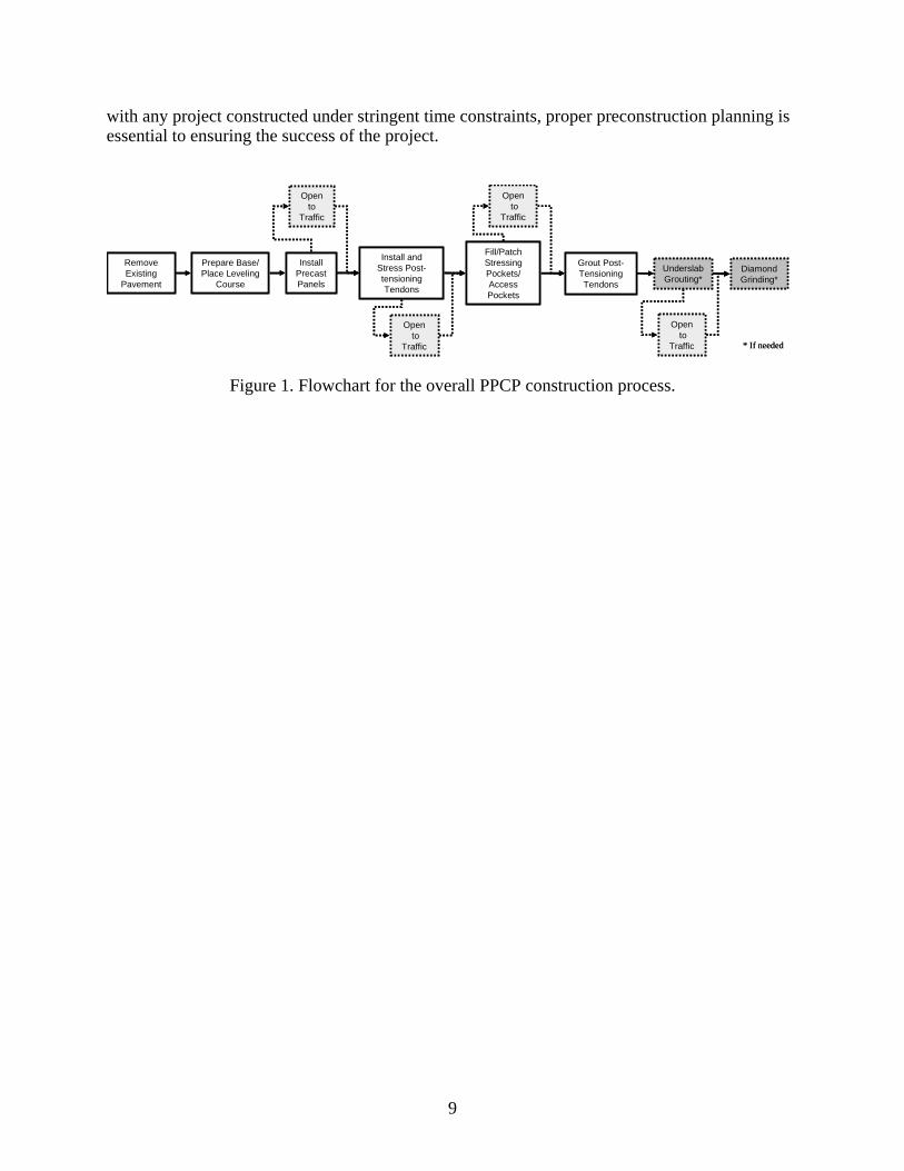
with any project constructed under stringent time constraints, proper preconstruction planning is essential to ensuring the success of the project.
Remove Existing
Pavement
Prepare Base/Place Leveling
Course
Install Precast Panels
Install and Stress Post-tensioning Tendons
Fill/Patch Stressing Pockets/Access Pockets
Grout Post-Tensioning Tendons
Open to
Traffic
Opento
Traffic
Opento
Traffic
Opento
Traffic
UnderslabGrouting*
Diamond Grinding*
* If needed
Figure 1. Flowchart for the overall PPCP construction process.
9
CHAPTER 3. IOWA HIGHWAY 60 DEMONSTRATION PROJECT
PROJECT SCOPE
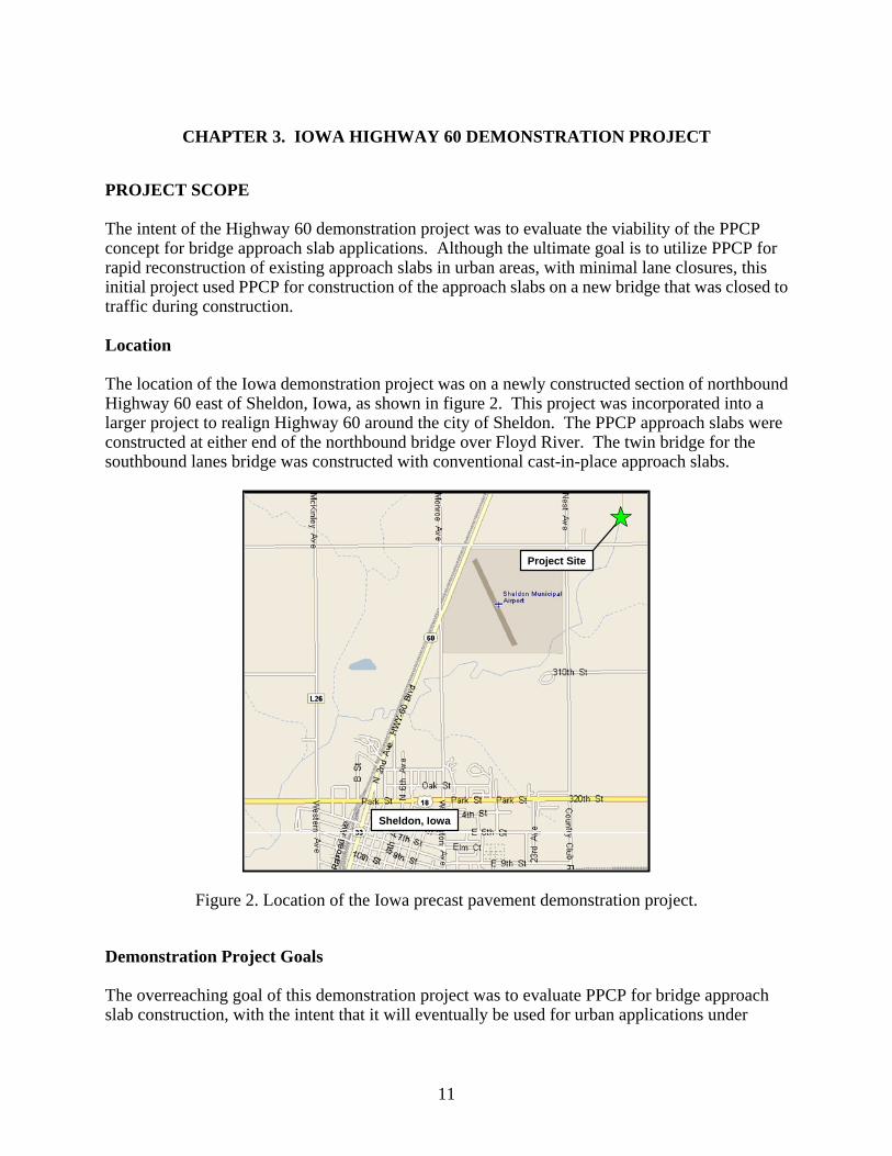
The intent of the Highway 60 demonstration project was to evaluate the viability of the PPCP concept for bridge approach slab applications. Although the ultimate goal is to utilize PPCP for rapid reconstruction of existing approach slabs in urban areas, with minimal lane closures, this initial project used PPCP for construction of the approach slabs on a new bridge that was closed to traffic during construction. Location
The location of the Iowa demonstration project was on a newly constructed section of northbound Highway 60 east of Sheldon, Iowa, as shown in figure 2. This project was incorporated into a larger project to realign Highway 60 around the city of Sheldon. The PPCP approach slabs were constructed at either end of the northbound bridge over Floyd River. The twin bridge for the southbound lanes bridge was constructed with conventional cast-in-place approach slabs.
Project Site
Sheldon, Iowa
Project Site
Sheldon, Iowa
Figure 2. Location of the Iowa precast pavement demonstration project.
Demonstration Project Goals
The overreaching goal of this demonstration project was to evaluate PPCP for bridge approach slab construction, with the intent that it will eventually be used for urban applications under
11

12
stringent time constraints. This evaluation included all aspects of the design and construction processes, including the design details, fabrication, and installation operations. Because this project was constructed on a section of roadway closed to traffic, it provided an opportunity to carefully evaluate the construction process to identify refinements that can be made to both the design details and construction requirements for future projects. A secondary goal of the Highway 60 demonstration project was to monitor PPCP approach slab behavior and performance over time for comparison with traditional cast-in-place approach slab construction. Extensive instrumentation of the approach slabs (both cast-in-place and precast), bridge girders, and bridge abutments was completed by the Bridge Engineering Center at Iowa State University, and will be described in more detail in Chapter 6. PARTNERING AND PROJECT COORDINATION
As with any project utilizing a construction technique for the first time, coordination between all parties throughout the project is essential. For the Highway 60 project IADOT designers and FHWA contractors worked closely together to develop a conceptual precast panel layout and initial design. These conceptual ideas were then used to solicit rough cost estimates from precasters. Once a precaster had been identified, the project team worked closely with them to develop the precast panel details to ensure a viable solution. The designers continued to work closely with the precaster throughout the fabrication process, and worked closely with the installation contractor throughout the construction of the project. PROJECT LAYOUT
Figure 3 shows the Situation Plan for the Highway 60 bridge, including the layout of the precast panels. The specific details of the project site and the process by which the precast panel layout was selected will be discussed below. Roadway Geometry
A tangent section of Highway 60 was selected for the location of the demonstration project. Although roadways with horizontal curves and superelevations may eventually be encountered, this project location allowed for evaluation of the overall process on a less complex pavement section. The roadway had a “rooftop” crown with two percent cross-slope on either side of the pavement centerline. This required a precast panel layout which could accommodate a crowned pavement section common in Iowa. As figure 3 shows, the bridge abutments were skewed at 30 degrees right ahead. While this presented a challenge in developing the layout of the precast panels, skewed bridges are common in Iowa and throughout the U.S., and this project allowed for the development of a solution which could accommodate skewed abutments.
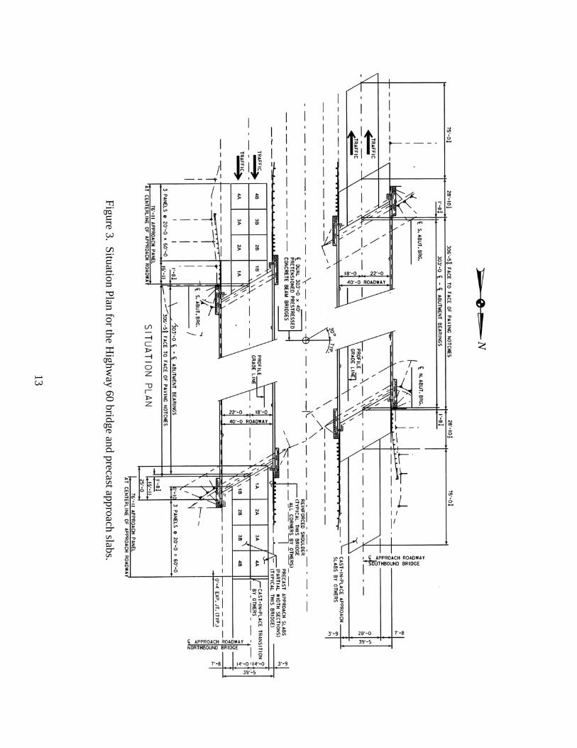
13
Figure 3. Situation Plan for the H
ighway 60 bridge and precast approach slabs.

Integral Bridge Abutment
The Highway 60 bridge was designed with an integral abutment. This type of bridge abutment moves horizontally with the expansion and contraction movement of the bridge itself. Normally, an expansion joint is provided between the abutment and approach slab to accommodate this movement. However, research by IADOT has found this expansion joint to be a source of water infiltration into the underlying embankment which can lead to consolidation or erosion of the embankment material.(13) A new approach slab detail being implemented by IADOT ties the approach slab to the abutment so that the approach slab moves with the abutment, shifting the expansion joint out to the end of the approach slab. This required consideration of the length of the approach slab not only to optimize how far the expansion joint is moved away from the abutment, but also what length of pavement could feasibly be “pushed” and “pulled” by the abutment without causing excessive stresses in the bridge structure. Precast Panel Layout Options
One of the underlying goals of this demonstration project was to develop a solution that is both practical from a fabrication and construction standpoint, and is adaptable to various approach slab configurations. Three options were considered for the precast panel layout in order to accommodate the approach slab characteristics listed above. These options were based primarily on precast panels that were used successfully on previous demonstration projects. The two preliminary alternate solutions are described below. Skewed full-width panels with variable thickness
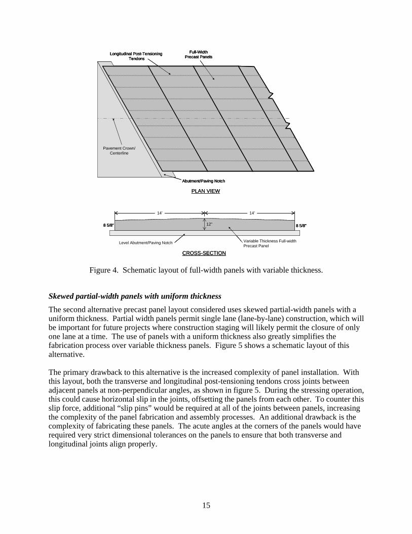
The first precast panel layout considered uses skewed full-width panels with variable thickness. Full-width panels have been used successfully in three previous demonstration projects in Texas, California, and Missouri,(2,3,6) and provide an efficient solution in terms of fabrication and installation as only half the number of panels are needed as compared to partial-width construction. Additionally, full-width panels with variable thickness were used successfully in California and Missouri to achieve the necessary change in cross-slope in the pavement surface. Figure 4 shows a schematic of the layout of skewed full-width panels with variable thickness. Full-width, variable thickness panels presented several drawbacks for application on this project. First, the paving notch on the bridge abutment would have required modification since it was constructed with a crowned cross section, and uniform 12 in. depth. A level (horizontal) paving notch would have been necessary for full-width panels with variable thickness. Paving notch modification for future rehabilitation projects with crowned paving notches will likely not be possible. Second, the complexity of fabricating full-width panels with both skewed edges and variable thickness would likely have significantly increased the cost of the panels. Finally, full-width panels would not have demonstrated single lane (or lane-by-lane) construction. While single lane construction was not required for the Highway 60 project, it will likely be required for future projects in urban areas to allow for traffic flow on the remaining lane(s).
14
Abutment/Paving Notch
Longitudinal Post-Tensioning Tendons
Pavement Crown/Centerline
Full-WidthPrecast Panels
8 5/8”12”8 5/8”
14’ 14’
Level Abutment/Paving Notch Variable Thickness Full-widthPrecast Panel
PLAN VIEW
CROSS-SECTION
Abutment/Paving Notch
Longitudinal Post-Tensioning Tendons
Pavement Crown/Centerline
Full-WidthPrecast Panels
Abutment/Paving Notch
Longitudinal Post-Tensioning Tendons
Pavement Crown/Centerline
Full-WidthPrecast Panels
8 5/8”12”8 5/8”
14’ 14’
Level Abutment/Paving Notch Variable Thickness Full-widthPrecast Panel
8 5/8”12”8 5/8”
14’ 14’
Level Abutment/Paving Notch Variable Thickness Full-widthPrecast Panel
PLAN VIEW
CROSS-SECTION
Figure 4. Schematic layout of full-width panels with variable thickness.
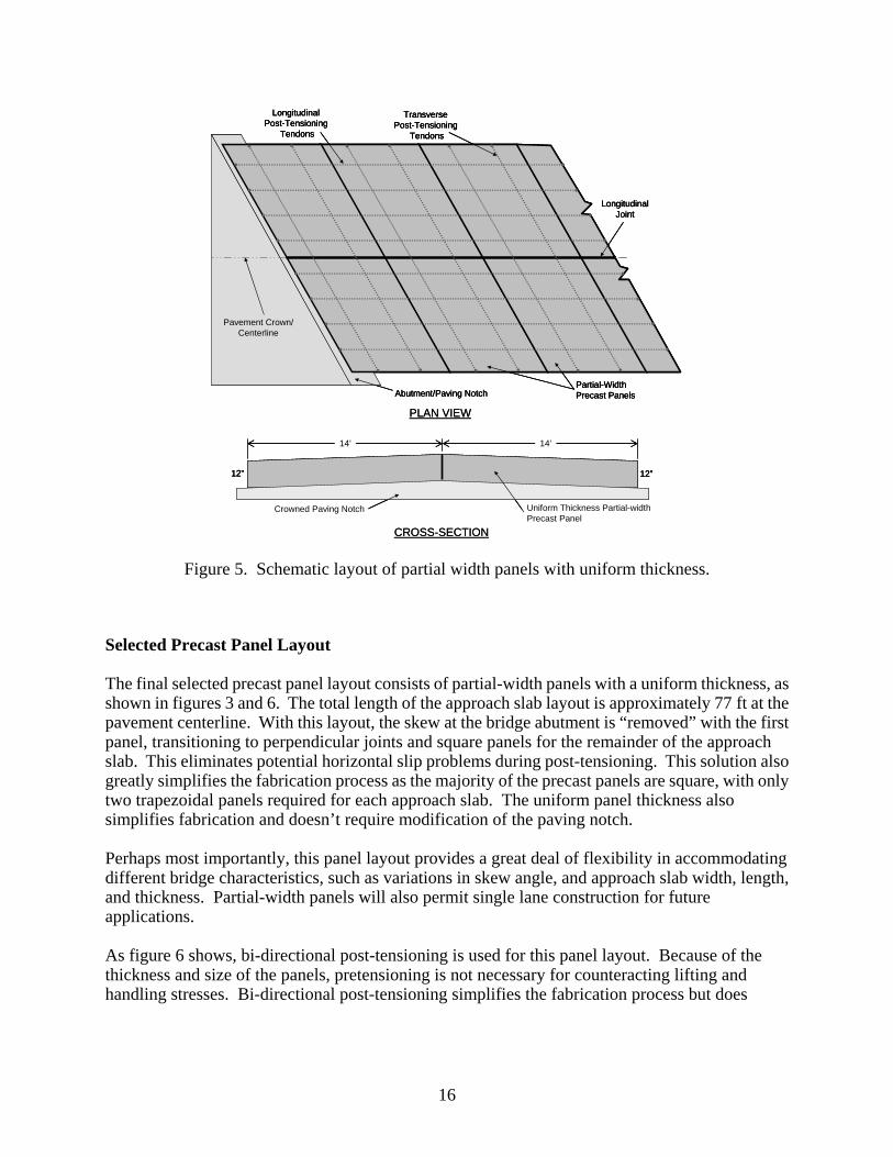
Skewed partial-width panels with uniform thickness
The second alternative precast panel layout considered uses skewed partial-width panels with a uniform thickness. Partial width panels permit single lane (lane-by-lane) construction, which will be important for future projects where construction staging will likely permit the closure of only one lane at a time. The use of panels with a uniform thickness also greatly simplifies the fabrication process over variable thickness panels. Figure 5 shows a schematic layout of this alternative. The primary drawback to this alternative is the increased complexity of panel installation. With this layout, both the transverse and longitudinal post-tensioning tendons cross joints between adjacent panels at non-perpendicular angles, as shown in figure 5. During the stressing operation, this could cause horizontal slip in the joints, offsetting the panels from each other. To counter this slip force, additional “slip pins” would be required at all of the joints between panels, increasing the complexity of the panel fabrication and assembly processes. An additional drawback is the complexity of fabricating these panels. The acute angles at the corners of the panels would have required very strict dimensional tolerances on the panels to ensure that both transverse and longitudinal joints align properly.
15
12”
14’ 14’
Crowned Paving Notch Uniform Thickness Partial-widthPrecast Panel
12”
PLAN VIEW
CROSS-SECTION
Abutment/Paving Notch
Longitudinal Post-Tensioning
Tendons
Pavement Crown/Centerline
LongitudinalJoint
Transverse Post-Tensioning
Tendons
Partial-WidthPrecast Panels
12”
14’ 14’
Crowned Paving Notch Uniform Thickness Partial-widthPrecast Panel
12”12”
14’ 14’
Crowned Paving Notch Uniform Thickness Partial-widthPrecast Panel
12”
PLAN VIEW
CROSS-SECTION
Abutment/Paving Notch
Longitudinal Post-Tensioning
Tendons
Pavement Crown/Centerline
LongitudinalJoint
Transverse Post-Tensioning
Tendons
Partial-WidthPrecast PanelsAbutment/Paving Notch
Longitudinal Post-Tensioning
Tendons
Pavement Crown/Centerline
LongitudinalJoint
Transverse Post-Tensioning
Tendons
Partial-WidthPrecast Panels
Figure 5. Schematic layout of partial width panels with uniform thickness.
Selected Precast Panel Layout
The final selected precast panel layout consists of partial-width panels with a uniform thickness, as shown in figures 3 and 6. The total length of the approach slab layout is approximately 77 ft at the pavement centerline. With this layout, the skew at the bridge abutment is “removed” with the first panel, transitioning to perpendicular joints and square panels for the remainder of the approach slab. This eliminates potential horizontal slip problems during post-tensioning. This solution also greatly simplifies the fabrication process as the majority of the precast panels are square, with only two trapezoidal panels required for each approach slab. The uniform panel thickness also simplifies fabrication and doesn’t require modification of the paving notch. Perhaps most importantly, this panel layout provides a great deal of flexibility in accommodating different bridge characteristics, such as variations in skew angle, and approach slab width, length, and thickness. Partial-width panels will also permit single lane construction for future applications. As figure 6 shows, bi-directional post-tensioning is used for this panel layout. Because of the thickness and size of the panels, pretensioning is not necessary for counteracting lifting and handling stresses. Bi-directional post-tensioning simplifies the fabrication process but does
16

require special attention to ensure that both the transverse and longitudinal post-tensioning ducts will align when the panels are installed.
Figure 6. Selected precast panel and post-tensioning tendon layout.
Panel Assembly
Figure 7 shows the final precast panel assembly. The first two panels resting on the paving notch are pinned to the abutment with dowels drilled and grouted into the paving notch. This causes the approach slab to move with the bridge abutment during seasonal temperature cycles. At the far end of the approach slab, a standard IADOT “EF” expansion joint (14) is constructed between the approach slab and adjoining pavement. The longitudinal joint at the centerline of the approach slab is a keyed grouted joint, as shown in figure 8, which is filled prior to completion of transverse post-tensioning. This type of joint provides tolerance for slight misalignment of the precast panels, and does not require a perfect fit between panels at the longitudinal joint.
17

Cast-in-place Grouted Joint
Transverse Post-TensioningAnchors
Post-Tensioning AnchorAccess Pockets
Paving Notch Anchor Pin Sleeves
Bridge Abutmentand Paving Notch
Bridge Deck
Figure 7. Selected precast panel layout.
Figure 8. Longitudinal joint at the centerline of the approach slab.
Panel Types
The panel layout consists of essentially three types of panels. The “abutment panels,” shown in figure 9, transition the joint in the approach slab from skewed to perpendicular. These panels have a variable length which can be adjusted based on the bridge skew. The panels have keyways cast into the mating edge of the panel. The panels also have anchor access pockets and paving notch anchor pin sleeves cast into them. The pockets provide access to all of the longitudinal post-tensioning anchors and the transverse post-tensioning anchors in the skewed section of the pavement (figure 6). The 2 in. diameter anchor pin sleeves receive dowels which anchor the approach slab to the abutment. The length of the abutment panels varies from 8 ft-10 in. to 16 ft-11 in. for the smaller of the two panels and 16 ft-11 in. to 25 ft for the larger of the two panels (see figure 6). The abutment panels are all 14 ft wide and 12 in. thick.
18

Continuous Shear Key
LiftingAnchors
Paving Notch Anchor Pin Sleeves
Post-TensioningAnchor Pockets
Figure 9. Approach slab Abutment Panels.
“Base panels,” shown in figure 10, are the “standard” panels that make up the majority of the approach slab. Keyways are cast into the mating edges of the panels and the transverse post-tensioning anchors are cast into the outside edges of the panels. Base panels for the Highway 60 project were 20 ft long, 14 ft wide, and 12 in. thick.
Continuous Shear Key
Post-Tensioning Ducts
LiftingAnchors
Transverse Post-Tensioning Anchors
Figure 10. Approach slab Base Panels.
Finally, the “joint panels” located at the end of the approach slab provide the transition to the adjoining cast-in-place pavement. Sleeves for the dowels used in the EF joint at the end of the approach slab are cast into the ends of these panels, as shown in figure 11. The live end post-tensioning anchors for the longitudinal tendons are cast into the ends of these panels as well.
19
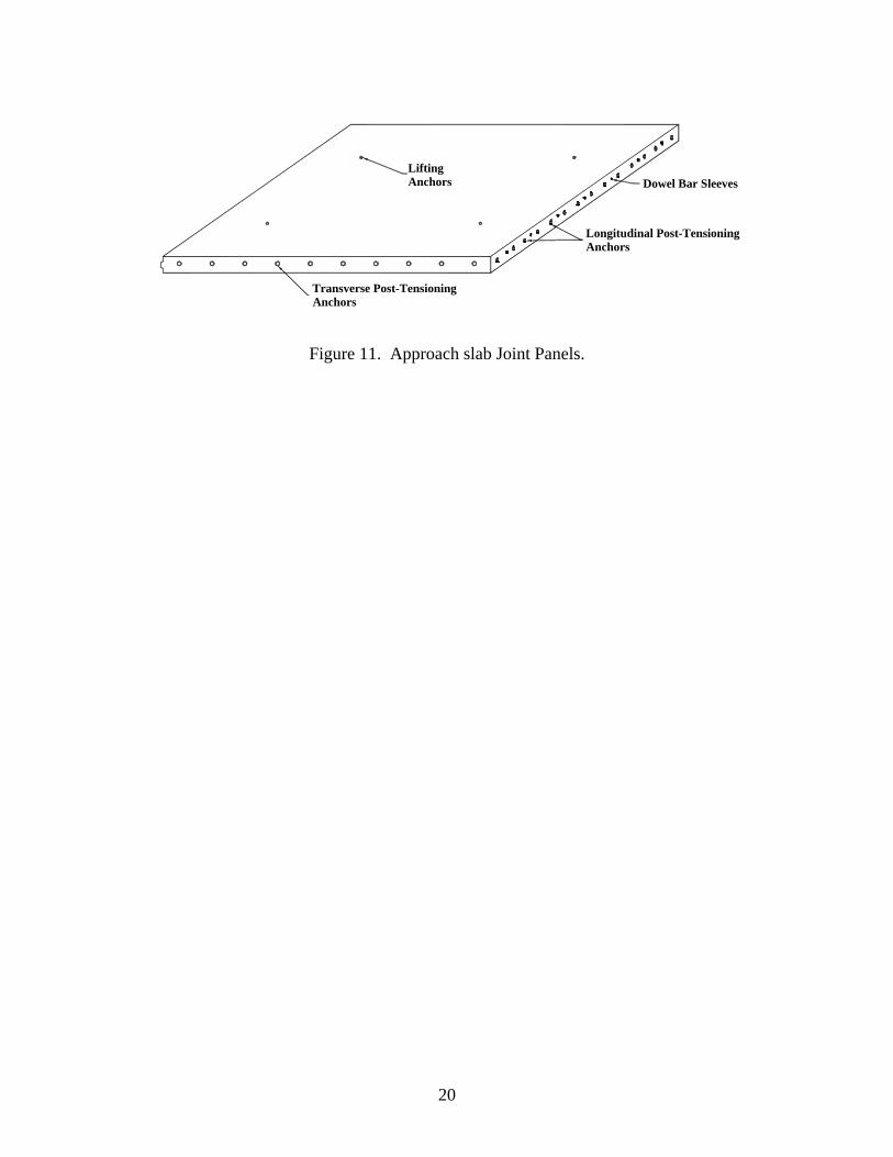
Dowel Bar Sleeves
Longitudinal Post-Tensioning Anchors
LiftingAnchors
Transverse Post-Tensioning Anchors
Figure 11. Approach slab Joint Panels.
20

CHAPTER 4. DESIGN
DESIGN CONSIDERATIONS
The Highway 60 site conditions dictated many of the approach slab characteristics, such as the overall slab length, width, and thickness. The design of the precast panels was therefore primarily used to determine the prestress requirements for the given slab characteristics. While design considerations for PPCP are discussed more thoroughly elsewhere(1,2), below are some of the design considerations specifically related to bridge approach slab applications. Slab Bridging
Pavements are normally designed such that they will withstand a given number of 18-kip equivalent single axle load applications (ESALs) over the life of the pavement.(15) Bridge approach slabs, however, present a unique design challenge in that a significant loss of support can be expected if voids form beneath pavement due to embankment consolidation or erosion. Traditional pavement design does not take such a significant loss of support into account. Therefore, the basis for the design of the Highway 60 project was to treat the approach slabs as a simply supported slab bridge spanning over a void in the underlying embankment extending away from the bridge abutment. Using this procedure, flexural stresses in the approach slab were determined and prestress levels were adjusted to ensure the slab had adequate flexural capacity. Traffic Loading
Traffic loading for traditional pavement design procedures is quantified by an estimate of the number of 18-kip ESALs the pavement will experience over its design life. However, because the Highway 60 approach slab was designed as a simply supported slab bridge, the traffic loading normally used for bridge design was used for calculation of flexural stresses in the approach slab. As per IADOT standard practice, HS 20 loading was used for the traffic loading on the approach slab.(16)
Bridge and Approach Slab Movement
Integral bridge abutments are designed to move horizontally (and rotate) with the expansion and contraction of the bridge itself. By tying the approach slab to the abutment, this movement must be accommodated at the expansion joint at the end of the approach slab. In addition, movement of the approach slab itself, which will expand and contract with daily and seasonal temperature cycles, must also be accommodated. The polyethylene friction reducing material beneath the approach slab will help reduce frictional restraint to movement of the approach slab, helping to reduce stresses in the approach slab and bridge structure. It is important that the connection between the bridge abutment and approach slab is strong enough to withstand the forces from the abutment “pushing” and “pulling” the approach slab.
21

HIGHWAY 60 PPCP DESIGN
The design procedure for the Highway 60 approach slabs was based on determining the prestress required to give the approach slab the flexural capacity to act as a simple span slab bridge for a given span length. For the initial design, a span length of 15 ft was used as voids up to this length were observed beneath existing approach slabs in Iowa in a recent study.(13) Traffic Loading
Traffic loading on the approach slab was based on HS 20 loading according to the AASHTO Standard Specifications for Highway Bridges.(16) Using this traffic loading design load moments were calculated for the following load combination:
LDLDTL 17.23.1)67.1(3.1 +=+= (Eq. 1) Live load moment was calculated using the estimate provided in section 3.24.3.2 of AASHTO specifications,(16) assuming a span length of 15 ft. Dead load moment was calculated for the self-weight of the approach slab with 12 in. thickness assuming a concrete unit weight of 150 lb/ft3. Table 1 summarizes the moments used for design for a 15 ft simple span approach slab.
Table 1. Factored design moments for Highway 60 approach slab (15 ft simple span).
Moment per ft of slab width (ft-lb)
Live Load 29,295 Dead Load 5,484 Total 34,779
Initial Flexural Design
The initial flexural design of the approach slab assumed a 15 ft simple span slab bridge with 12 in. slab thickness. Initially, the prestressing tendons were assumed to be at mid depth of the slab. Prestress levels in the slab were adjusted by varying the spacing of the prestressing tendons, the depth of the tendons, and the type of prestressing material (7-wire strand and high-strength bars). The AASHTO Load Factor Design method for flexure was used to compute the ultimate moment capacity of the simply supported approach slab. The following equations from section 9.17.2 of the AASHTO specifications were used to compute flexural strength.(16) Although mild steel reinforcement was included in the precast panels, the initial design only considered the prestressed reinforcement in carrying tensile stresses since mild steel reinforcement will not be continuous through the approach slab (between precast panels).
22

⎥⎥⎦
⎤
⎢⎢⎣
⎡⎟⎟⎠
⎞⎜⎜⎝
⎛−=
c
sususn f
fpdfAM
'6.01
****φφ (Eq. 2)
⎟⎟⎠
⎞⎜⎜⎝
⎛−=
c
sssu f
fpff
''
1' *
1
**
βγ (Eq. 3)
A*
s = Area of prestressing steel f*
su = Yield strength of prestressing steel f’s = Ultimate strength of prestressing steel f’c = Concrete compressive strength p* = Reinforcement ratio for prestressing steel β1 = Concrete strength factor φ = Strength-reduction factor (0.9 for flexure) Variations of both prestressing strand configurations and high-strength prestressing bars were used for the capacity analysis. Table 2 summarizes the flexural capacity of the approach slab with these varying configurations. Any of these configurations will provide the necessary flexural capacity for a 15 ft simply supported approach slab.
Table 2. Flexural capacity of various prestressing configurations.
Tendon Spacing (inches)
Depth from Surface (inches)
Flexural Capacity per foot of slab width
(ft-lb) 12 8.75 35,500 0.6” Grade 270 Strand 8 6.25 34,835 24 8.25 35,907 1” Dia. 12 6 40,380 Grade 150 Bar
1.25” Dia. 24 6.5 36,014 Final Flexural Design
While the prestressing configurations presented above will provide the necessary flexural capacity for a 15 ft simply supported approach slab (using only prestressing steel to carry tensile stresses), the prestressing required is significantly more than that used for previous projects and IADOT believed it to be excessive for this application. Therefore, a standard 24 in. monostrand tendon spacing, using 0.6 in. Grade 270 7-wire strand, was specified for the final prestressing configuration. Using this standard spacing of 24 in., the allowable span length was back-calculated based on the flexural capacity of the slab. The calculated allowable span length considering just the prestressing steel for carrying tensile stresses is approximately 6.1 ft. When also considering the contribution of the mild steel in the bottom of the precast panels No. 8, Grade 60 reinforcing bars at 12 in. on center in the longitudinal direction) for carrying tensile stresses, the spanning ability of
23

the approach slab increases to approximately 18.8 ft. The mild steel reinforcement in the precast panels may or may not contribute to flexural capacity since it is not continuous through the approach slab (i.e., it is isolated in each individual precast panel). If a void were to form directly beneath one of the individual precast panels, the mild reinforcement would likely give the approach slab this additional flexural capacity; but if a void formed beneath multiple panels, it may not provide this additional capacity. It should be noted that designing an approach slab for flexural capacity is believed to be a very conservative approach as voids as large as 15 ft, while they have been observed, are likely very rare. Additionally, failure of an approach slab due to exceeding the flexural capacity would not likely have catastrophic consequences on the safety of the motoring public, as it could for a bridge. Transverse Prestress
Transverse prestress was specified the same as the longitudinal prestress, with monostrand tendons spaced at 24 in. on center over the length of the approach slab. However, because the transverse post-tensioning tendons follow the contour of the crowned pavement cross-section (figure 8), there was the potential for the prestress force to cause uplift of the precast panels during stressing, hinging about the longitudinal joint. A calculation of these uplift forces, which are resisted by both the weight of the precast panels and the horizontal component of the prestressing force, revealed that the total uplift force was only 32 percent of the resistance to uplift, and therefore would not present a problem. Slab Movement Analysis
Normally, the expansion and contraction movement of a precast post-tensioned pavement slab is a governing factor in determining how long each post-tensioned section of panels should be. For the Highway 60 approach slab, however, the length of the approach slab was predetermined, and the slab movement analysis was only used to ensure that the expansion joint at the end of the approach slab was adequate. By tying the approach slabs to the integral abutments of the bridge, the approach slabs will be “pushed” and “pulled” by the abutments with movement of the bridge itself. IADOT estimated the total movement of each end of the bridge to be approximately 1.3 in. Expansion and contraction movements of the approach slab itself were calculated using a methodology originally developed for cast-in-place post-tensioned pavement.(11,17) This methodology takes into account the slab geometry (length, width, and thickness), concrete properties (modulus of elasticity, coefficient of thermal expansion, creep and shrinkage), prestress (and prestress losses), slab-base frictional resistance, and local temperatures for summer and winter conditions. Both long-term (seasonal) movements as well as short-term (daily) movements of the slab are taken into account. Table 3 shows the results of the slab movement analysis for the Highway 60 bridge approach slabs. The values shown in this table represent the maximum anticipated movement of the free end of the approach slabs at the centerline, “short,” and “long” edges of the approach slabs. This movement is additive to the 1.3 in. anticipated from bridge movement. The expansion joint at the free end of the approach slab, therefore, should be able to accommodate the “Total Movement” of up to 1.74 in. shown in Table 3.
24

Table 3. Predicted movements at the ends of the approach slabs.
Approach Slab Length Approach Slab
Movement Total Movement 69 ft (short edge) 0.36 in. 1.66 in. 77 ft (centerline) 0.40 in. 1.70 in. 85 ft (long edge) 0.44 in. 1.74 in.
25


CHAPTER 5. PANEL FABRICATION
PROCEDURE
The precast panels for the Highway 60 approach slabs were fabricated by IPC, Inc. in Iowa Falls, Iowa. The fabrication plant was located approximately 175 miles from the site location in Sheldon, Iowa. The panels were fabricated on an indoor bed large enough to cast one panel at a time. Because of the limited number of panels for the project, a larger fabrication operation (e.g., long line fabrication) was not necessary. Also, because pretensioning was not used, the panels did not need to be cast on a bed set up for prestressing. The sideforms were specially made for this project in-house by IPC using laminate wood. In general, bed setup took approximately a full day to complete, particularly for the abutment panels which had additional reinforcement and post-tensioning anchor pockets. Concrete placement for each panel was completed in approximately 30-45 minutes. Following surface finishing, curing compound was applied to the panel surface and the panel was then covered and heat cured overnight. In general, the panels were removed from the forms the day after casting and stacked for storage in the yard. Additional details of the fabrication process will be discussed below. TOLERANCES
As with all previous PPCP demonstration projects, the precast panels for the Highway 60 project were not match-cast. This required special attention to tolerances to ensure that adjoining panels would fit together and provide a satisfactory riding surface. Table 4 summarizes the tolerances for the precast panels as specified in the project plans. It is important to note that while most of these tolerances are tighter than normally specified for similar precast products and those recommended by the Precast/Prestressed Concrete Institute, they are based on experience from previous demonstration projects in which there were no problems in achieving these tolerances. PANEL DETAILS
The Highway 60 approach slab was a very unique application for precast prestressed concrete pavement and required unique details to be developed. Below are some of the key details of the precast panels (see Appendix for all detailed panel drawings). Keyways
Keyways were used for both the transverse joints between individual panels, and for the longitudinal joint at the centerline of the pavement. The primary purpose of the transverse keyways was to help ensure vertical alignment between panels as they were assembled. This permitted the panels to be installed over a base that was not perfectly flat while still providing load transfer between panels prior to post-tensioning. Figure 12 shows the transverse keyway dimensions. These dimensions, which were based on experience with previous PPCP demonstration projects, ensured no more than a 1/4 in. vertical differential between panels, while
27
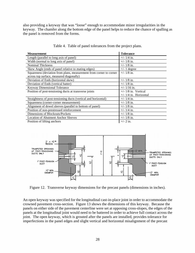
also providing a keyway that was “loose” enough to accommodate minor irregularities in the keyway. The chamfer along the bottom edge of the panel helps to reduce the chance of spalling as the panel is removed from the forms.
Table 4. Table of panel tolerances from the project plans.
Measurement Tolerance Length (parallel to long axis of panel) +/- 1/4 in. Width (normal to long axis of panel) +/- 1/8 in. Nominal Thickness +/- 1/8 in. Skew Angle (ends of panel relative to mating edges) +/- 1 degree Squareness (deviation from plans, measurement from corner to corner across top surface, measured diagonally)
+/- 1/8 in.
Deviation of Ends (horizontal skew) +/- 1/8 in. Deviation of Ends (vertical batter) +/- 1/8 in. Keyway Dimensional Tolerance +/- 1/16 in. Position of post-tensioning ducts at transverse joints +/- 1/8 in. Vertical
+/- 1/4 in. Horizontal Straightness of post-tensioning ducts (vertical and horizontal) +/- 1/4 in. Squareness (corner-corner measurement) +/- 1/8 in. Alignment of dowel sleeves (parallel to bottom of panel) +/- 1/8 in. Position of non-prestressed reinforcement +/- 1/4 in. Dimensions of Blockouts/Pockets +/- 1/8 in. Location of Abutment Anchor Sleeves +/- 1/8 in. Position of lifting anchors +/- 2 in.
Figure 12. Transverse keyway dimensions for the precast panels (dimensions in inches).
An open keyway was specified for the longitudinal cast-in-place joint in order to accommodate the crowned pavement cross-section. Figure 13 shows the dimensions of this keyway. Because the panels on either side of the pavement centerline were set at opposing cross-slopes, the edges of the panels at the longitudinal joint would need to be battered in order to achieve full contact across the joint. The open keyway, which is grouted after the panels are installed, provides tolerance for imperfections in the panel edges and slight vertical and horizontal misalignment of the precast
28
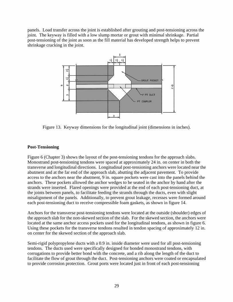
panels. Load transfer across the joint is established after grouting and post-tensioning across the joint. The keyway is filled with a low slump mortar or grout with minimal shrinkage. Partial post-tensioning of the joint as soon as the fill material has developed strength helps to prevent shrinkage cracking in the joint.
Figure 13. Keyway dimensions for the longitudinal joint (dimensions in inches).
Post-Tensioning
Figure 6 (Chapter 3) shows the layout of the post-tensioning tendons for the approach slabs. Monostrand post-tensioning tendons were spaced at approximately 24 in. on center in both the transverse and longitudinal directions. Longitudinal post-tensioning anchors were located near the abutment and at the far end of the approach slab, abutting the adjacent pavement. To provide access to the anchors near the abutment, 9 in. square pockets were cast into the panels behind the anchors. These pockets allowed the anchor wedges to be seated in the anchor by hand after the strands were inserted. Flared openings were provided at the end of each post-tensioning duct, at the joints between panels, to facilitate feeding the strands through the ducts, even with slight misalignment of the panels. Additionally, to prevent grout leakage, recesses were formed around each post-tensioning duct to receive compressible foam gaskets, as shown in figure 14. Anchors for the transverse post-tensioning tendons were located at the outside (shoulder) edges of the approach slab for the non-skewed section of the slab. For the skewed section, the anchors were located at the same anchor access pockets used for the longitudinal tendons, as shown in figure 6. Using these pockets for the transverse tendons resulted in tendon spacing of approximately 12 in. on center for the skewed section of the approach slab. Semi-rigid polypropylene ducts with a 0.9 in. inside diameter were used for all post-tensioning tendons. The ducts used were specifically designed for bonded monostrand tendons, with corrugations to provide better bond with the concrete, and a rib along the length of the duct to facilitate the flow of grout through the duct. Post-tensioning anchors were coated or encapsulated to provide corrosion protection. Grout ports were located just in front of each post-tensioning
29
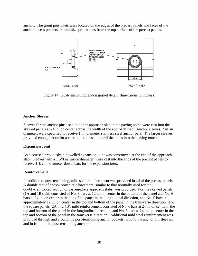
anchor. The grout port inlets were located on the edges of the precast panels and faces of the anchor access pockets to minimize protrusions from the top surface of the precast panels.
Figure 14. Post-tensioning tendon gasket detail (dimensions in inches).
Anchor Sleeves
Sleeves for the anchor pins used to tie the approach slab to the paving notch were cast into the skewed panels at 24 in. on center across the width of the approach slab. Anchor sleeves, 2 in. in diameter, were specified to receive 1 in. diameter stainless steel anchor bars. The larger sleeves provided enough room for a core bit to be used to drill the holes into the paving notch. Expansion Joint
As discussed previously, a dowelled expansion joint was constructed at the end of the approach slab. Sleeves with a 1 5/8 in. inside diameter, were cast into the ends of the precast panels to receive 1 1/2 in. diameter dowel bars for the expansion joint. Reinforcement
In addition to post-tensioning, mild steel reinforcement was provided in all of the precast panels. A double mat of epoxy-coated reinforcement, similar to that normally used for the doubly-reinforced section of cast-in-place approach slabs, was provided. For the skewed panels (1A and 1B), this consisted of No. 8 bars at 12 in. on center in the bottom of the panel and No. 6 bars at 24 in. on center in the top of the panel in the longitudinal direction, and No. 5 bars at approximately 12 in. on center in the top and bottom of the panel in the transverse direction. For the square panels (2A thru 4B), mild reinforcement consisted of No. 6 bars at 24 in. on center in the top and bottom of the panel in the longitudinal direction, and No. 5 bars at 24 in. on center in the top and bottom of the panel in the transverse direction. Additional mild steel reinforcement was provided through and around the post-tensioning anchor pockets, around the anchor pin sleeves, and in front of the post-tensioning anchors.
30
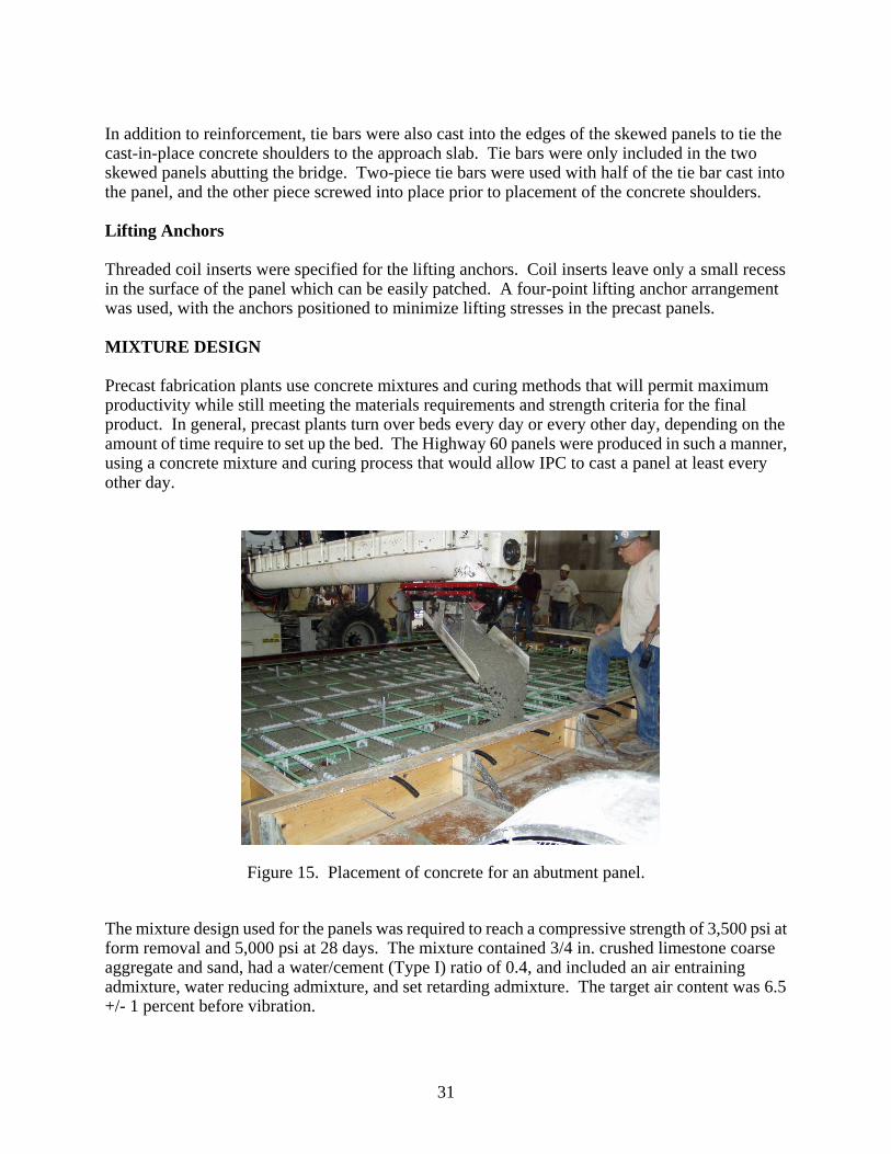
In addition to reinforcement, tie bars were also cast into the edges of the skewed panels to tie the cast-in-place concrete shoulders to the approach slab. Tie bars were only included in the two skewed panels abutting the bridge. Two-piece tie bars were used with half of the tie bar cast into the panel, and the other piece screwed into place prior to placement of the concrete shoulders. Lifting Anchors
Threaded coil inserts were specified for the lifting anchors. Coil inserts leave only a small recess in the surface of the panel which can be easily patched. A four-point lifting anchor arrangement was used, with the anchors positioned to minimize lifting stresses in the precast panels. MIXTURE DESIGN
Precast fabrication plants use concrete mixtures and curing methods that will permit maximum productivity while still meeting the materials requirements and strength criteria for the final product. In general, precast plants turn over beds every day or every other day, depending on the amount of time require to set up the bed. The Highway 60 panels were produced in such a manner, using a concrete mixture and curing process that would allow IPC to cast a panel at least every other day.
Figure 15. Placement of concrete for an abutment panel.
The mixture design used for the panels was required to reach a compressive strength of 3,500 psi at form removal and 5,000 psi at 28 days. The mixture contained 3/4 in. crushed limestone coarse aggregate and sand, had a water/cement (Type I) ratio of 0.4, and included an air entraining admixture, water reducing admixture, and set retarding admixture. The target air content was 6.5 +/- 1 percent before vibration.
31
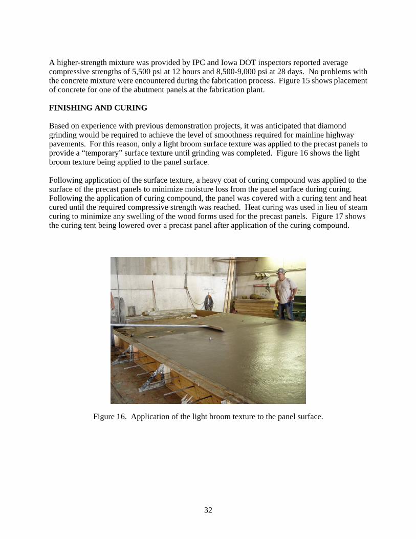
A higher-strength mixture was provided by IPC and Iowa DOT inspectors reported average compressive strengths of 5,500 psi at 12 hours and 8,500-9,000 psi at 28 days. No problems with the concrete mixture were encountered during the fabrication process. Figure 15 shows placement of concrete for one of the abutment panels at the fabrication plant. FINISHING AND CURING
Based on experience with previous demonstration projects, it was anticipated that diamond grinding would be required to achieve the level of smoothness required for mainline highway pavements. For this reason, only a light broom surface texture was applied to the precast panels to provide a “temporary” surface texture until grinding was completed. Figure 16 shows the light broom texture being applied to the panel surface. Following application of the surface texture, a heavy coat of curing compound was applied to the surface of the precast panels to minimize moisture loss from the panel surface during curing. Following the application of curing compound, the panel was covered with a curing tent and heat cured until the required compressive strength was reached. Heat curing was used in lieu of steam curing to minimize any swelling of the wood forms used for the precast panels. Figure 17 shows the curing tent being lowered over a precast panel after application of the curing compound.
Figure 16. Application of the light broom texture to the panel surface.
32
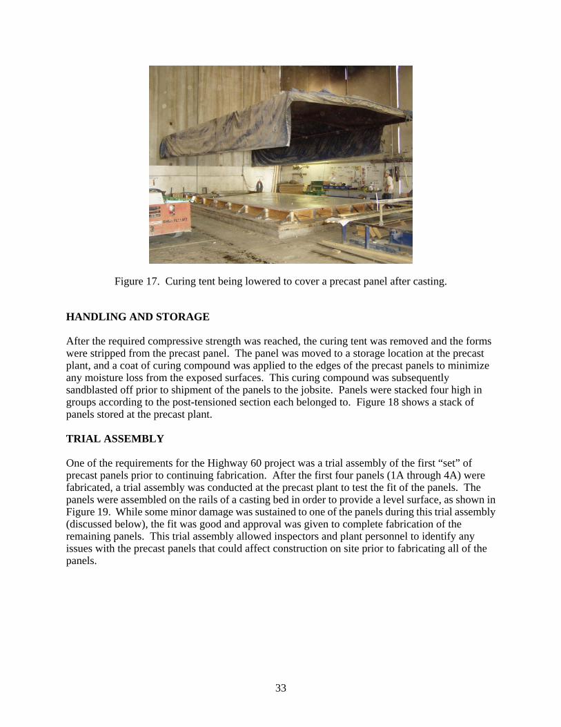
Figure 17. Curing tent being lowered to cover a precast panel after casting.
HANDLING AND STORAGE
After the required compressive strength was reached, the curing tent was removed and the forms were stripped from the precast panel. The panel was moved to a storage location at the precast plant, and a coat of curing compound was applied to the edges of the precast panels to minimize any moisture loss from the exposed surfaces. This curing compound was subsequently sandblasted off prior to shipment of the panels to the jobsite. Panels were stacked four high in groups according to the post-tensioned section each belonged to. Figure 18 shows a stack of panels stored at the precast plant. TRIAL ASSEMBLY
One of the requirements for the Highway 60 project was a trial assembly of the first “set” of precast panels prior to continuing fabrication. After the first four panels (1A through 4A) were fabricated, a trial assembly was conducted at the precast plant to test the fit of the panels. The panels were assembled on the rails of a casting bed in order to provide a level surface, as shown in Figure 19. While some minor damage was sustained to one of the panels during this trial assembly (discussed below), the fit was good and approval was given to complete fabrication of the remaining panels. This trial assembly allowed inspectors and plant personnel to identify any issues with the precast panels that could affect construction on site prior to fabricating all of the panels.
33
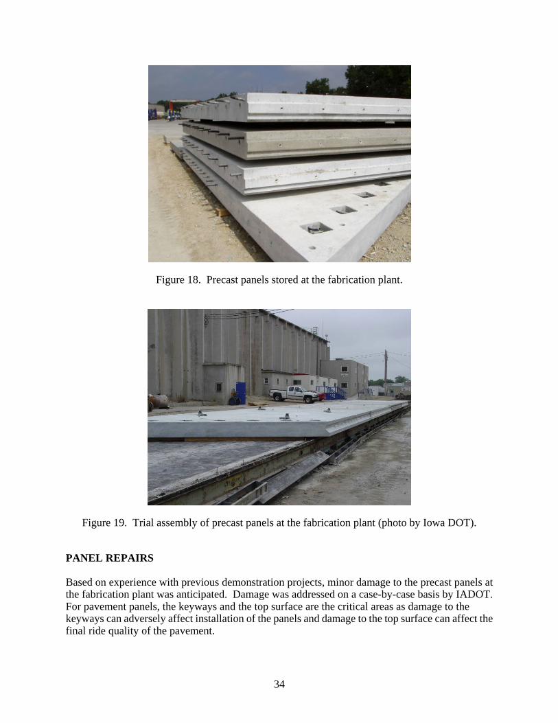
Figure 18. Precast panels stored at the fabrication plant.
Figure 19. Trial assembly of precast panels at the fabrication plant (photo by Iowa DOT).
PANEL REPAIRS
Based on experience with previous demonstration projects, minor damage to the precast panels at the fabrication plant was anticipated. Damage was addressed on a case-by-case basis by IADOT. For pavement panels, the keyways and the top surface are the critical areas as damage to the keyways can adversely affect installation of the panels and damage to the top surface can affect the final ride quality of the pavement.
34

Based on damage sustained at the precast plant during the trial assembly and general handling, a repair procedure was established by IADOT. Any deep spalls, corner breaks, or keyway fractures were required to be removed, cleaned, and patched. One significant corner repair and one keyway repair were required from damage during the trial assembly, as shown in figures 20 and 21. In addition to damage sustained during the trial assembly, additional grinding of the keyways was required prior to shipping the panels to the project site. As figure 22 shows, mortar trapped behind the keyway former on some of the sideforms, and swelling of the forms due to repeated use, resulted in battered top and bottom vertical faces on a few of the panels. This batter was removed by grinding the face of the keyway so that it was vertical and true. Figure 23 shows the keyway surface after grinding, prior to installation of the panel.
Figure 20. Damaged panel corner after trial assembly.
35
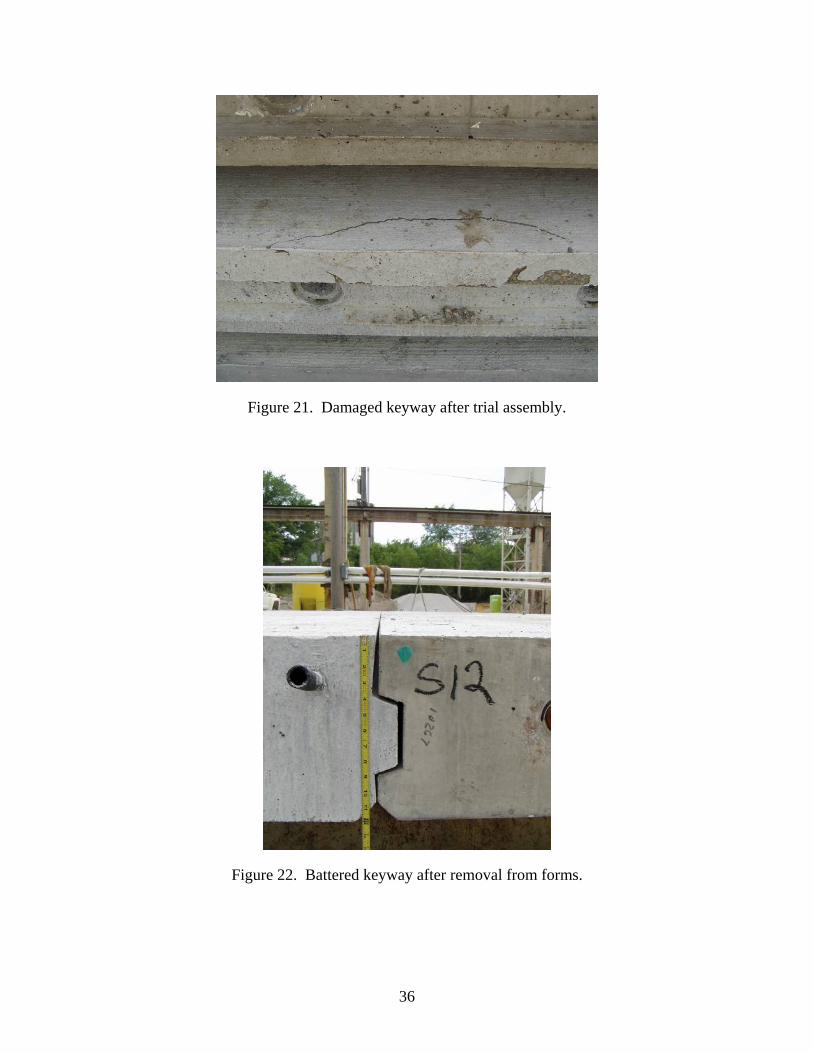
Figure 21. Damaged keyway after trial assembly.
Figure 22. Battered keyway after removal from forms.
36

Figure 23. Keyway after completion of grinding.
FABRICATION ISSUES AND CHALLENGES
While the fabrication process was completely successful and no precast panels were rejected, several issues were discovered during the course of the process. Below are some of the key issues which need to be specifically addressed for future projects. Post-Tensioning Ducts
The post-tensioning ducts used for this project are ideal for monostrand post-tensioning tendons. However, because this duct material has some flexibility, it requires bar stiffeners to be inserted into the ducts prior to placing concrete in the forms. It also requires adequate chairing to prevent the duct from sagging. Pocket Reinforcement
As mentioned above, additional reinforcement was provided around the post-tensioning anchor access pockets. Combined with the reinforcement for the anchor pin sleeves, this created a very congested region around the pockets. This required a significant amount of time to tie all of the reinforcement and required special attention to concrete placement around the pockets to ensure that concrete had filled in around all of the reinforcement. For future projects, different options for reinforcing this region should be examined in order to reduce congestion. Formwork
As discussed above, the wood sideforms used for the precast panels accumulated mortar beneath the keyway former, resulting in vertical batter of the keyway faces for some of the panels. While
37

wood forms provide an economical solution and can be manufactured to the tolerances required for this type of fabrication, they are probably not suitable for significant reuse. Although they can be much more costly, larger projects may necessitate the use of steel forms which are more durable and are less susceptible to the issues encountered with the Highway 60 panels. Panel Damage
The primary damage that occurred at the fabrication plant happened during the trial assembly. While this damage was adequately repaired, damage to precast pavement panels should be avoided at all costs as it can cause problems with the assembly of the panels and can also affect the smoothness of the riding surface. For future projects, damage tolerances and repair procedures should be prepared and approved in advance of the fabrication process so they can be addressed and resolved quickly.
38
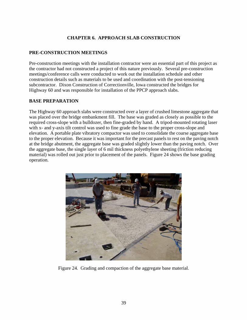
CHAPTER 6. APPROACH SLAB CONSTRUCTION
PRE-CONSTRUCTION MEETINGS
Pre-construction meetings with the installation contractor were an essential part of this project as the contractor had not constructed a project of this nature previously. Several pre-construction meetings/conference calls were conducted to work out the installation schedule and other construction details such as materials to be used and coordination with the post-tensioning subcontractor. Dixon Construction of Correctionville, Iowa constructed the bridges for Highway 60 and was responsible for installation of the PPCP approach slabs. BASE PREPARATION
The Highway 60 approach slabs were constructed over a layer of crushed limestone aggregate that was placed over the bridge embankment fill. The base was graded as closely as possible to the required cross-slope with a bulldozer, then fine-graded by hand. A tripod-mounted rotating laser with x- and y-axis tilt control was used to fine grade the base to the proper cross-slope and elevation. A portable plate vibratory compactor was used to consolidate the coarse aggregate base to the proper elevation. Because it was important for the precast panels to rest on the paving notch at the bridge abutment, the aggregate base was graded slightly lower than the paving notch. Over the aggregate base, the single layer of 6 mil thickness polyethylene sheeting (friction reducing material) was rolled out just prior to placement of the panels. Figure 24 shows the base grading operation.
Figure 24. Grading and compaction of the aggregate base material.
39
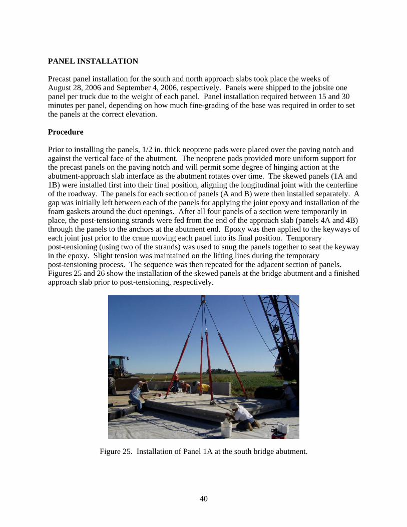
PANEL INSTALLATION
Precast panel installation for the south and north approach slabs took place the weeks of August 28, 2006 and September 4, 2006, respectively. Panels were shipped to the jobsite one panel per truck due to the weight of each panel. Panel installation required between 15 and 30 minutes per panel, depending on how much fine-grading of the base was required in order to set the panels at the correct elevation. Procedure
Prior to installing the panels, 1/2 in. thick neoprene pads were placed over the paving notch and against the vertical face of the abutment. The neoprene pads provided more uniform support for the precast panels on the paving notch and will permit some degree of hinging action at the abutment-approach slab interface as the abutment rotates over time. The skewed panels (1A and 1B) were installed first into their final position, aligning the longitudinal joint with the centerline of the roadway. The panels for each section of panels (A and B) were then installed separately. A gap was initially left between each of the panels for applying the joint epoxy and installation of the foam gaskets around the duct openings. After all four panels of a section were temporarily in place, the post-tensioning strands were fed from the end of the approach slab (panels 4A and 4B) through the panels to the anchors at the abutment end. Epoxy was then applied to the keyways of each joint just prior to the crane moving each panel into its final position. Temporary post-tensioning (using two of the strands) was used to snug the panels together to seat the keyway in the epoxy. Slight tension was maintained on the lifting lines during the temporary post-tensioning process. The sequence was then repeated for the adjacent section of panels. Figures 25 and 26 show the installation of the skewed panels at the bridge abutment and a finished approach slab prior to post-tensioning, respectively.
Figure 25. Installation of Panel 1A at the south bridge abutment.
40
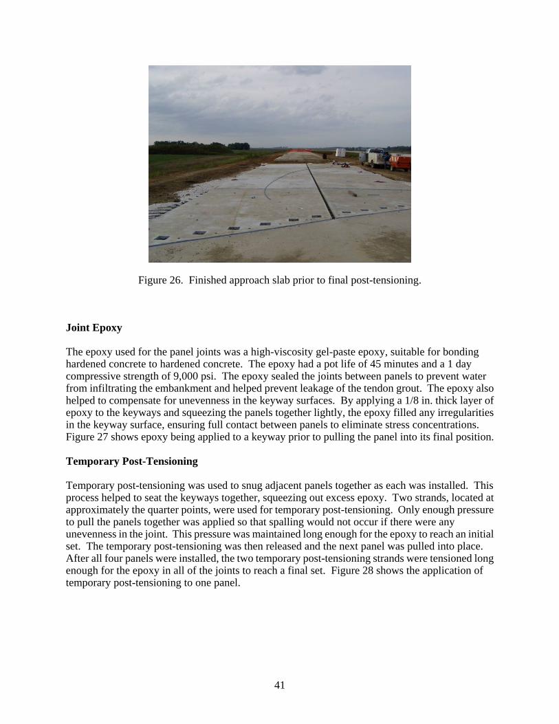
Figure 26. Finished approach slab prior to final post-tensioning.
Joint Epoxy
The epoxy used for the panel joints was a high-viscosity gel-paste epoxy, suitable for bonding hardened concrete to hardened concrete. The epoxy had a pot life of 45 minutes and a 1 day compressive strength of 9,000 psi. The epoxy sealed the joints between panels to prevent water from infiltrating the embankment and helped prevent leakage of the tendon grout. The epoxy also helped to compensate for unevenness in the keyway surfaces. By applying a 1/8 in. thick layer of epoxy to the keyways and squeezing the panels together lightly, the epoxy filled any irregularities in the keyway surface, ensuring full contact between panels to eliminate stress concentrations. Figure 27 shows epoxy being applied to a keyway prior to pulling the panel into its final position. Temporary Post-Tensioning
Temporary post-tensioning was used to snug adjacent panels together as each was installed. This process helped to seat the keyways together, squeezing out excess epoxy. Two strands, located at approximately the quarter points, were used for temporary post-tensioning. Only enough pressure to pull the panels together was applied so that spalling would not occur if there were any unevenness in the joint. This pressure was maintained long enough for the epoxy to reach an initial set. The temporary post-tensioning was then released and the next panel was pulled into place. After all four panels were installed, the two temporary post-tensioning strands were tensioned long enough for the epoxy in all of the joints to reach a final set. Figure 28 shows the application of temporary post-tensioning to one panel.
41

Figure 27. Application of joint epoxy during panel installation.
Figure 28. Temporary post-tensioning used to pull panels together.
POST-TENSIONING
All transverse and longitudinal post-tensioning tendons consisted of single 0.6 in. diameter, Grade 270 7-wire strand. The longitudinal post-tensioning strands were fed through the ducts as the panels were installed to ensure that all strands could be inserted. After all of the panels for each
42
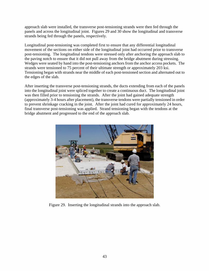
approach slab were installed, the transverse post-tensioning strands were then fed through the panels and across the longitudinal joint. Figures 29 and 30 show the longitudinal and transverse strands being fed through the panels, respectively. Longitudinal post-tensioning was completed first to ensure that any differential longitudinal movement of the sections on either side of the longitudinal joint had occurred prior to transverse post-tensioning. The longitudinal tendons were stressed only after anchoring the approach slab to the paving notch to ensure that it did not pull away from the bridge abutment during stressing. Wedges were seated by hand into the post-tensioning anchors from the anchor access pockets. The strands were tensioned to 75 percent of their ultimate strength or approximately 203 ksi. Tensioning began with strands near the middle of each post-tensioned section and alternated out to the edges of the slab. After inserting the transverse post-tensioning strands, the ducts extending from each of the panels into the longitudinal joint were spliced together to create a continuous duct. The longitudinal joint was then filled prior to tensioning the strands. After the joint had gained adequate strength (approximately 3-4 hours after placement), the transverse tendons were partially tensioned in order to prevent shrinkage cracking in the joint. After the joint had cured for approximately 24 hours, final transverse post-tensioning was applied. Strand tensioning began with the tendons at the bridge abutment and progressed to the end of the approach slab.
Figure 29. Inserting the longitudinal strands into the approach slab.
43

Figure 30. Inserting the transverse strands into the approach slab.
GROUTING
Grouting was completed after all post-tensioning had been completed and the pockets (anchor access and instrumentation pockets) and longitudinal joint had been filled. Initially, tendon grouting was started prior to underslab grouting. However, after experiencing significant grout leakage from the tendons, the process was reversed and underslab grouting was completed first. Tendon Grouting
As discussed previously, the purpose of grouting the post-tensioning tendons is to both provide an additional layer of corrosion protection for the strands, and to bond the strands to the concrete so that individual panels can be cut out and removed in the future for repairs or replacement without compromising the prestress of the entire approach slab. A prepackaged cable grout mixture, specifically formulated for post-tensioning strands, was used for the tendon grout. Grout was pumped from the inlet port at the anchor at one end of the tendon to the port at the anchor at the other end of the tendon. Although some grout leakage was observed when grouting the longitudinal tendons, grout flow from the outlet of each tendon indicated full grouting. No leakage was observed during transverse tendon grouting. Figure 31 shows the tendon grouting operation.
44
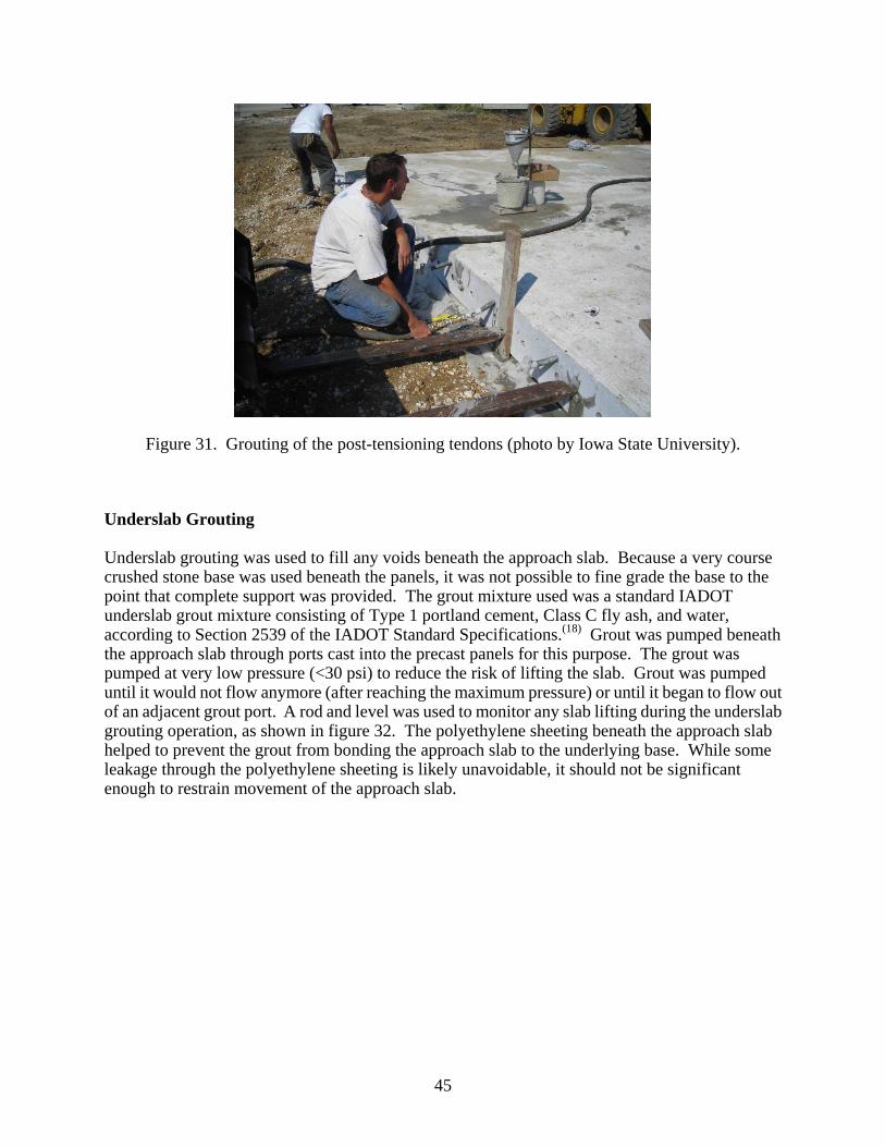
Figure 31. Grouting of the post-tensioning tendons (photo by Iowa State University).
Underslab Grouting
Underslab grouting was used to fill any voids beneath the approach slab. Because a very course crushed stone base was used beneath the panels, it was not possible to fine grade the base to the point that complete support was provided. The grout mixture used was a standard IADOT underslab grout mixture consisting of Type 1 portland cement, Class C fly ash, and water, according to Section 2539 of the IADOT Standard Specifications.(18) Grout was pumped beneath the approach slab through ports cast into the precast panels for this purpose. The grout was pumped at very low pressure (<30 psi) to reduce the risk of lifting the slab. Grout was pumped until it would not flow anymore (after reaching the maximum pressure) or until it began to flow out of an adjacent grout port. A rod and level was used to monitor any slab lifting during the underslab grouting operation, as shown in figure 32. The polyethylene sheeting beneath the approach slab helped to prevent the grout from bonding the approach slab to the underlying base. While some leakage through the polyethylene sheeting is likely unavoidable, it should not be significant enough to restrain movement of the approach slab.
45
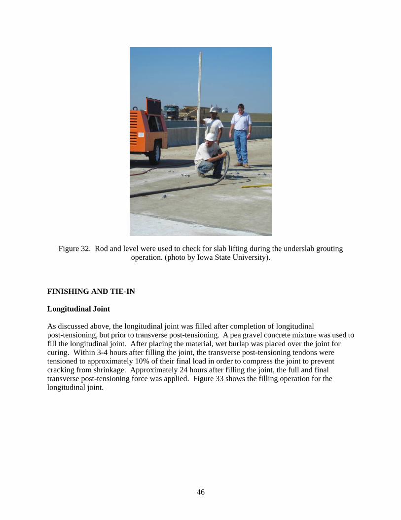
Figure 32. Rod and level were used to check for slab lifting during the underslab grouting operation. (photo by Iowa State University).
FINISHING AND TIE-IN
Longitudinal Joint
As discussed above, the longitudinal joint was filled after completion of longitudinal post-tensioning, but prior to transverse post-tensioning. A pea gravel concrete mixture was used to fill the longitudinal joint. After placing the material, wet burlap was placed over the joint for curing. Within 3-4 hours after filling the joint, the transverse post-tensioning tendons were tensioned to approximately 10% of their final load in order to compress the joint to prevent cracking from shrinkage. Approximately 24 hours after filling the joint, the full and final transverse post-tensioning force was applied. Figure 33 shows the filling operation for the longitudinal joint.
46
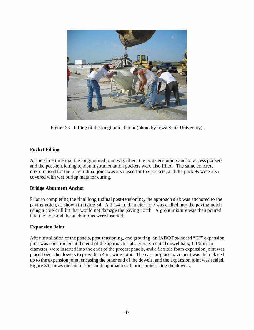
Figure 33. Filling of the longitudinal joint (photo by Iowa State University).
Pocket Filling
At the same time that the longitudinal joint was filled, the post-tensioning anchor access pockets and the post-tensioning tendon instrumentation pockets were also filled. The same concrete mixture used for the longitudinal joint was also used for the pockets, and the pockets were also covered with wet burlap mats for curing. Bridge Abutment Anchor
Prior to completing the final longitudinal post-tensioning, the approach slab was anchored to the paving notch, as shown in figure 34. A 1 1/4 in. diameter hole was drilled into the paving notch using a core drill bit that would not damage the paving notch. A grout mixture was then poured into the hole and the anchor pins were inserted. Expansion Joint
After installation of the panels, post-tensioning, and grouting, an IADOT standard “EF” expansion joint was constructed at the end of the approach slab. Epoxy-coated dowel bars, 1 1/2 in. in diameter, were inserted into the ends of the precast panels, and a flexible foam expansion joint was placed over the dowels to provide a 4 in. wide joint. The cast-in-place pavement was then placed up to the expansion joint, encasing the other end of the dowels, and the expansion joint was sealed. Figure 35 shows the end of the south approach slab prior to inserting the dowels.
47
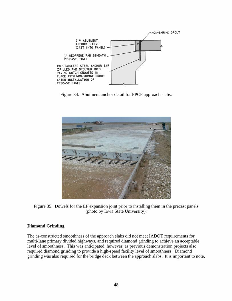
Figure 34. Abutment anchor detail for PPCP approach slabs.
Figure 35. Dowels for the EF expansion joint prior to installing them in the precast panels (photo by Iowa State University).
Diamond Grinding
The as-constructed smoothness of the approach slabs did not meet IADOT requirements for multi-lane primary divided highways, and required diamond grinding to achieve an acceptable level of smoothness. This was anticipated, however, as previous demonstration projects also required diamond grinding to provide a high-speed facility level of smoothness. Diamond grinding was also required for the bridge deck between the approach slabs. It is important to note,
48
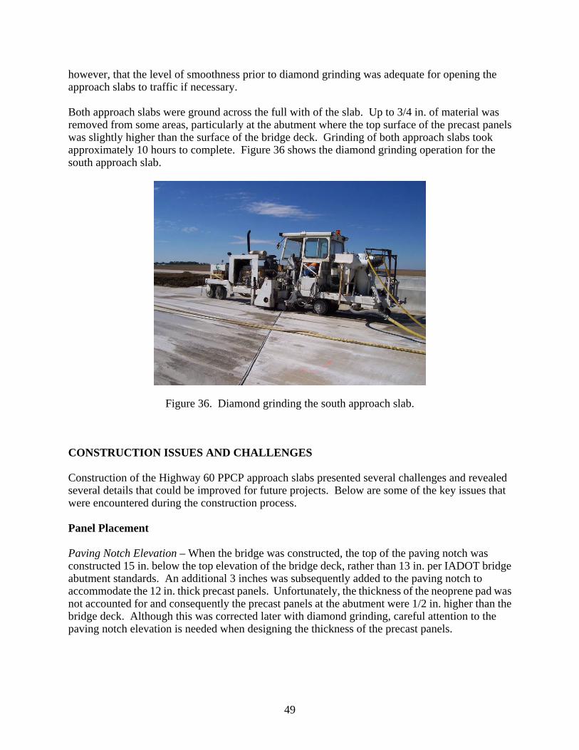
however, that the level of smoothness prior to diamond grinding was adequate for opening the approach slabs to traffic if necessary. Both approach slabs were ground across the full with of the slab. Up to 3/4 in. of material was removed from some areas, particularly at the abutment where the top surface of the precast panels was slightly higher than the surface of the bridge deck. Grinding of both approach slabs took approximately 10 hours to complete. Figure 36 shows the diamond grinding operation for the south approach slab.
Figure 36. Diamond grinding the south approach slab.
CONSTRUCTION ISSUES AND CHALLENGES
Construction of the Highway 60 PPCP approach slabs presented several challenges and revealed several details that could be improved for future projects. Below are some of the key issues that were encountered during the construction process. Panel Placement
Paving Notch Elevation – When the bridge was constructed, the top of the paving notch was constructed 15 in. below the top elevation of the bridge deck, rather than 13 in. per IADOT bridge abutment standards. An additional 3 inches was subsequently added to the paving notch to accommodate the 12 in. thick precast panels. Unfortunately, the thickness of the neoprene pad was not accounted for and consequently the precast panels at the abutment were 1/2 in. higher than the bridge deck. Although this was corrected later with diamond grinding, careful attention to the paving notch elevation is needed when designing the thickness of the precast panels.
49
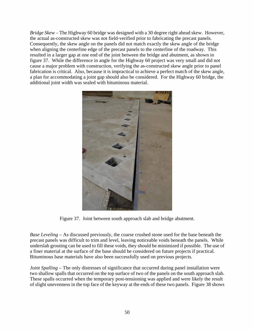
Bridge Skew – The Highway 60 bridge was designed with a 30 degree right ahead skew. However, the actual as-constructed skew was not field-verified prior to fabricating the precast panels. Consequently, the skew angle on the panels did not match exactly the skew angle of the bridge when aligning the centerline edge of the precast panels to the centerline of the roadway. This resulted in a larger gap at one end of the joint between the bridge and abutment, as shown in figure 37. While the difference in angle for the Highway 60 project was very small and did not cause a major problem with construction, verifying the as-constructed skew angle prior to panel fabrication is critical. Also, because it is impractical to achieve a perfect match of the skew angle, a plan for accommodating a joint gap should also be considered. For the Highway 60 bridge, the additional joint width was sealed with bituminous material.
Figure 37. Joint between south approach slab and bridge abutment.
Base Leveling – As discussed previously, the coarse crushed stone used for the base beneath the precast panels was difficult to trim and level, leaving noticeable voids beneath the panels. While underslab grouting can be used to fill these voids, they should be minimized if possible. The use of a finer material at the surface of the base should be considered on future projects if practical. Bituminous base materials have also been successfully used on previous projects. Joint Spalling – The only distresses of significance that occurred during panel installation were two shallow spalls that occurred on the top surface of two of the panels on the south approach slab. These spalls occurred when the temporary post-tensioning was applied and were likely the result of slight unevenness in the top face of the keyway at the ends of these two panels. Figure 38 shows
50
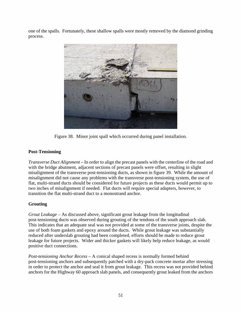
one of the spalls. Fortunately, these shallow spalls were mostly removed by the diamond grinding process.
Figure 38. Minor joint spall which occurred during panel installation.
Post-Tensioning
Transverse Duct Alignment – In order to align the precast panels with the centerline of the road and with the bridge abutment, adjacent sections of precast panels were offset, resulting in slight misalignment of the transverse post-tensioning ducts, as shown in figure 39. While the amount of misalignment did not cause any problems with the transverse post-tensioning system, the use of flat, multi-strand ducts should be considered for future projects as these ducts would permit up to two inches of misalignment if needed. Flat ducts will require special adapters, however, to transition the flat multi-strand duct to a monostrand anchor. Grouting
Grout Leakage – As discussed above, significant grout leakage from the longitudinal post-tensioning ducts was observed during grouting of the tendons of the south approach slab. This indicates that an adequate seal was not provided at some of the transverse joints, despite the use of both foam gaskets and epoxy around the ducts. While grout leakage was substantially reduced after underslab grouting had been completed, efforts should be made to reduce grout leakage for future projects. Wider and thicker gaskets will likely help reduce leakage, as would positive duct connections. Post-tensioning Anchor Recess – A conical shaped recess is normally formed behind post-tensioning anchors and subsequently patched with a dry-pack concrete mortar after stressing in order to protect the anchor and seal it from grout leakage. This recess was not provided behind anchors for the Highway 60 approach slab panels, and consequently grout leaked from the anchors
51
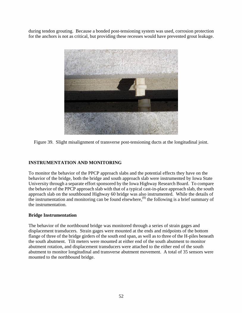
during tendon grouting. Because a bonded post-tensioning system was used, corrosion protection for the anchors is not as critical, but providing these recesses would have prevented grout leakage.
Figure 39. Slight misalignment of transverse post-tensioning ducts at the longitudinal joint.
INSTRUMENTATION AND MONITORING
To monitor the behavior of the PPCP approach slabs and the potential effects they have on the behavior of the bridge, both the bridge and south approach slab were instrumented by Iowa State University through a separate effort sponsored by the Iowa Highway Research Board. To compare the behavior of the PPCP approach slab with that of a typical cast-in-place approach slab, the south approach slab on the southbound Highway 60 bridge was also instrumented. While the details of the instrumentation and monitoring can be found elsewhere,(8) the following is a brief summary of the instrumentation. Bridge Instrumentation
The behavior of the northbound bridge was monitored through a series of strain gages and displacement transducers. Strain gages were mounted at the ends and midpoints of the bottom flange of three of the bridge girders of the south end span, as well as to three of the H-piles beneath the south abutment. Tilt meters were mounted at either end of the south abutment to monitor abutment rotation, and displacement transducers were attached to the either end of the south abutment to monitor longitudinal and transverse abutment movement. A total of 35 sensors were mounted to the northbound bridge.
52
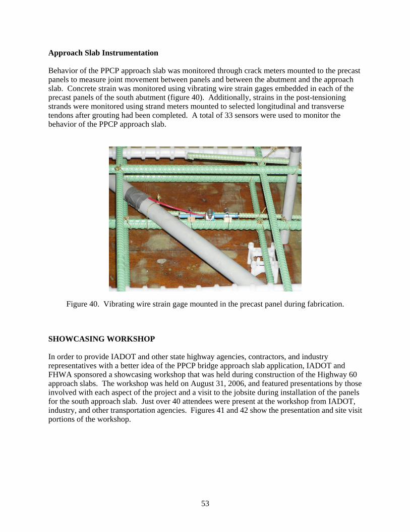
Approach Slab Instrumentation
Behavior of the PPCP approach slab was monitored through crack meters mounted to the precast panels to measure joint movement between panels and between the abutment and the approach slab. Concrete strain was monitored using vibrating wire strain gages embedded in each of the precast panels of the south abutment (figure 40). Additionally, strains in the post-tensioning strands were monitored using strand meters mounted to selected longitudinal and transverse tendons after grouting had been completed. A total of 33 sensors were used to monitor the behavior of the PPCP approach slab.
Figure 40. Vibrating wire strain gage mounted in the precast panel during fabrication.
SHOWCASING WORKSHOP
In order to provide IADOT and other state highway agencies, contractors, and industry representatives with a better idea of the PPCP bridge approach slab application, IADOT and FHWA sponsored a showcasing workshop that was held during construction of the Highway 60 approach slabs. The workshop was held on August 31, 2006, and featured presentations by those involved with each aspect of the project and a visit to the jobsite during installation of the panels for the south approach slab. Just over 40 attendees were present at the workshop from IADOT, industry, and other transportation agencies. Figures 41 and 42 show the presentation and site visit portions of the workshop.
53

Figure 41. Presentations were provided by those involved in the Highway 60 project.
Figure 42. Site visit during installation of the precast approach slab.
54

CHAPTER 7. PROJECT EVALUATION AND RECOMMENDATIONS FOR FUTURE PROJECTS
The Highway 60 approach slab demonstration project provided many unique challenges for the design and construction of precast prestressed concrete pavement. Many new ideas were developed and many lessons were learned throughout the course of the project. Some of the more salient issues related to the overall project layout, design, fabrication, and construction are presented below with recommendations for future projects. PROJECT LAYOUT
The precast panel layout for the Highway 60 project worked very well. Using the first two panels at the abutment to “remove” the skew from the approach slab minimized the number of specialty panels that had to be fabricated. Using rectangular panels of the same size for the majority of the approach slab greatly simplified panel fabrication and installation. Two-way post-tensioning also simplified fabrication by eliminating pretensioning. The cast-in-place keyed longitudinal joint accommodated the crowned pavement section and simplified fabrication of the mating panel edges. Transverse post-tensioning will keep the longitudinal joint in compression and help ensure that it remains closed over time. Dowel sleeves cast into the ends of the precast panels facilitated construction of the expansion joint at the end of the approach slab and eliminated the need for any connection to tie or anchor the approach slab to the adjoining pavement. Future projects, which may not have a leave-out for cast-in-place pavement at the end of the approach slab, will require some technique for dowelling the approach slab to existing pavement. A similar panel layout should be considered for future projects. This layout provides flexibility with varying skew angles, pavement cross sections (crowned or uniform cross slope), and approach slab length and width. Also, by using partial-width panels, lane-by-lane construction can be utilized when full closure of the approach slab is not possible during reconstruction. Two-way post-tensioning should also be considered for future projects, but larger panel sizes may necessitate pretensioning to compensate for lifting and handling stresses. An alternative panel layout proposed by IADOT would use only a single panel on either side of the longitudinal joint. These panels would likely be pretensioned in the longitudinal direction for handling purposes and post-tensioned together across the longitudinal joint after installation. The ends of the precast panels would be skewed to match the bridge abutment skew. This panel layout would limit the length of the approach slab (and the distance the expansion joint is from the abutment) to the maximum length of precast panel that could be safely fabricated, handled, and shipped. This layout option will likely be considered for future approach slab reconstruction projects.
55

DESIGN
Design Procedures
As discussed in Chapter 4, no design procedures for precast prestressed bridge approach slabs have been established. The methodology employed for the Highway 60 approach slabs was a design for flexure, treating the approach slab as a simple span “slab bridge.” While this provided a sound procedure for approach slab design, it resulted in very high prestress requirements for the Highway 60 approach slabs, particularly if the contribution of the mild steel reinforcement to flexural strength is ignored. For future projects, other design procedures may be examined or standardized prestress requirements could be adopted based on the Highway 60 project. Design Details
While many of the basic design details stemmed from previous PPCP demonstration projects, most had to be modified for this project, and other unique details had to be developed. Keyways – The keyway dimensions for the Highway 60 precast panels were based on dimensions used successfully for previous demonstration projects in Texas, California, and Missouri. Because of the increased panel thickness, however, the depth of the interior vertical face was increased to provide more surface area around the post-tensioning ducts to seal the duct openings better. The keyways helped align the panels vertically and resulted in a satisfactory finished surface with essentially no “faults” or lips at the joints between panels. Similar keyway dimensions should be considered for future projects. Longitudinal Joint – The primary benefit of the cast-in-place keyed longitudinal joint was accommodation of the crowned pavement cross-section, permitting the panels on either side of the joint to be set at opposing cross-slopes. While a cast-in-place joint does add an additional step to the construction process, the amount of fill material needed was minimal, and if necessary, the joint could have been temporarily filled or covered and opened to traffic prior to filling. A similar longitudinal joint detail should be considered for future projects with crowned cross-sections. For a uniform cross-slope, a butt joint could potentially be used at the longitudinal joint. Post-tensioning Anchor Pockets – In detailing the post-tensioning anchor pockets, the goal was to keep them as small as possible while making them large enough to permit the post-tensioning anchor wedges to be manually inserted in the anchors. While the contractor would have preferred larger pockets, the size was adequate for inserting the anchor wedges by hand, and it also minimized the amount of fill required. Similar pocket dimensions should be considered for future projects. It is important to note, however, that these smaller pockets can only be used for dead-end post-tensioning anchors and not for feeding the strands into the ducts. It some situations it may be necessary to feed the post-tensioning strands from the “bridge end” of the approach slab rather than at the “pavement end.” In this situation, it may be possible to cast narrow slots into the surface of the panels, behind the anchor pockets, that are wide enough to receive the post-tensioning strands as they are fed into the anchors. This would allow the strands to be laid out on the bridge deck prior to feeding them through the panels.
56

Abutment Anchor – The pins drilled and grouted into the paving notch provided a simple solution for anchoring the approach slab to the abutment. Instrumentation on the south approach slab will provide an indication of how well the pinned connections perform. Future projects should consider a similar detail, but may also consider an option for post-tensioning the approach slab to the abutment. While post-tensioning to the abutment would add complexity to the construction process and would require very careful attention in matching the skew angle of the approach slab to the abutment, a post-tensioned connection may provide a tighter and more durable joint, reducing the probability of water infiltration at the joint. Underslab Grouting – The ports cast into the precast panels for underslab grouting appeared to be adequate for ensuring that voids beneath the precast panels were filled. In most instances, grout pumped into one port could be seen flowing from an adjacent port, indicating full grouting beneath the slab. Similar grout port details should be provided for future projects. PANEL FABRICATION
Below are some of the key aspects of the panel fabrication process for the Highway 60 project and recommendations for future projects. Tolerances – Other than problems with out-of-tolerance keyways, discussed in Chapter 5, no problems were reported in achieving the specified tolerances. These tolerances should be used as a baseline for future projects. Formwork – As discussed in Chapter 5, with a very limited number of panels to fabricate, the precast producer opted to use wood formwork for the panels, and no problems were reported in achieving the tolerances specified in the contract documents. There were, however, problems with the keyway sideforms that occurred over the course of the fabrication process, as discussed in Chapter 5. These problems could be mitigated on future projects with closer inspection of the sideforms on a daily basis. Alternatively, steel sideforms which are produced to very precise tolerances and less susceptible to problems that occur with continual reuse, may be used. Steel forms may not be cost-effective for smaller projects with a very limited number of panels, however. Reinforcement – No problems were reported with the reinforcement layout other than around the post-tensioning anchor access pockets where reinforcement was somewhat congested and difficult to install properly. For future projects, the reinforcement layout in the anchor region should be re-evaluated to ensure that there will not be any problems with placing the reinforcement and placing the concrete around the reinforcement. Finishing – Neither the precast producer nor IADOT inspectors reported any problems with the finishing operation. A uniform panel thickness kept the finishing process simple, with a vibratory screed used to level the top surface of the precast panels. A light broom texture was applied to the surface to provide “temporary” texture until diamond grinding was completed. Also benefiting the finishing operation was minimizing the number of protrusions from the panel surface. Only the tubes used to form the underslab grout ports and the post-tensioning anchor/instrumentation pockets were protruding from the surface.
57
For future projects, uniform thickness panels should be specified whenever possible, although previous demonstration projects have successfully used variable thickness panels. The precast producer should also try to minimize protrusions from the panel surface. When diamond grinding is anticipated, a light broom texture should provide adequate surface texture until diamond grinding is complete. Curing – No problems were reported with the panel curing operation. A heavy coat of curing compound was applied to the panel surface after texturing, and the panels were then heat-cured overnight. Curing compound was applied to the edges of the panels after they were removed from the forms and later sandblasted from the keyway prior to shipment of the panels. This curing process produced the concrete strength required by the precaster and did not result in any noticeable shrinkage cracking in the panels. A similar process should be utilized on future projects, although other alternative curing processes such as steam curing and wet mat curing have been successfully used elsewhere. Handling and Storage – Although some minor damage was sustained when handling the precast panels at the fabrication plant, no major problems with handling and storage were encountered. The threaded insert lifting anchors were adequate for the project and left only a small hole in the panel surface to be filled. CONSTRUCTION
Panel installation was a successful process, as discussed in Chapter 6. There were, however, some issues that could possibly be improved for future projects. Base Preparation
Materials – While the crushed limestone aggregate worked adequately for the base beneath the Highway 60 approach slabs, the coarse nature of the material made it difficult to grade precisely, leaving voids beneath the approach slabs. While underslab grouting filled these voids, ideally they should be minimized during grading of the base. The use of a finer material which can be graded easier at the surface, should be considered for future projects. Any finer material that is used, however, should be checked to see that it has the necessary drainage characteristics and that it doesn’t have an excessive percentage of very fine (passing No. 200 sieve) particles. Leveling Technique – The crushed limestone base was graded by hand and compacted with a portable plate vibrator. A rotating laser mounted on a tripod, which is commonly used for site grading, established the grade line and two percent cross slope for the surface of the aggregate base. This technique provides a very precise grade line and should be utilized for future projects whenever possible. Alternative Techniques – An alternative technique proposed by the contractor for quickly establishing the proper elevation would be to set steel plates on the base at the proper elevation at the location of the corners of the precast panels. Setting the precast panels on these steel plates would ensure that the surface of the pavement was at the proper elevation and cross-slope. The void beneath the pavement would then be filled with grout or flowable fill through underslab grout ports in the panel. While this technique would likely require a significant amount of
58
grout/flowable fill beneath the approach slab, it would minimize time-consuming precision grading of the base. If this technique is utilized on future projects, however, it is essential that the grouting operation be completed prior to opening the pavement to traffic as the panels would only be supported at the corners prior to grouting. Panel Installation
Joint Treatment/Epoxy – High viscosity gel-paste epoxy was applied to the panel keyways as they were installed. This epoxy helped lubricate the keyways for installation and sealed the joints to prevent water intrusion. The epoxy also helped to compensate for slight unevenness and irregularities in the mating surfaces of the panels. The epoxy filled in any “low” areas of the keyway such that the panels were in complete contact across the joint. This type of epoxy material and assembly technique should be utilized for future projects, particularly if unevenness is observed in the keyways. If unevenness is observed, it is important that only partial post-tensioning force be applied to the joint until the epoxy has set, as stress concentrations from non-uniform contact could result in spalling of the keyway if the full post-tensioning force were applied. When using this “two stage” post-tensioning process under strict time constraints (e.g., overnight construction), an epoxy with an appropriate set time should be used. Temporary Post-Tensioning – The purpose of temporary post-tensioning is to close the joints between panels as much as possible prior to final post-tensioning. It has been used successfully on all previous demonstration projects, and was beneficial for the Highway 60 project as well. Depending on the size of the precast panels, no more than two panels should be installed between temporary stressing operations. If an epoxy with a short pot life is used, temporary post-tensioning should be applied after each panel is installed to ensure that the panels are fully bedded in the epoxy before it sets. Panel/Duct Alignment – No problems were experienced with longitudinal post-tensioning duct alignment. A mark on the top surface of the precast panels at mating joints above a given post-tensioning duct should always be used for alignment, rather than aligning the ends of the panels. This will help to ensure alignment of the post-tensioning ducts even if the edges of the panels do not line up. As discussed in Chapter 7, there was slight misalignment of the transverse post-tensioning ducts across the longitudinal joint. While this minor misalignment did not cause any problems, provision should be made to allow for slight misalignment. For future projects with a longitudinal joint, flat (1 in. by 3 in.) post-tensioning ducts should be considered for the transverse tendons. These will permit as much as 2 in. of misalignment across the longitudinal joint. Post-tensioning
Ducts – The post-tensioning ducts used for the Highway 60 project are ideally suited for bonded monostrand post-tensioning tendons. The polyethylene duct material is corrosion resistant, and the channels running along the length of the duct facilitate the flow of grout even if a strand is pressing against the duct. Although the precast producer reported some challenges with installing the ducts in the forms, this material is recommended for future projects. A larger diameter duct or flat duct of the same material will permit some misalignment of the panels.
59
Post-tensioning Tendons – No problems were reported with the strand used for the post-tensioning tendons. Grade 270, 0.6 in. diameter strand is commonly used in the post-tensioning industry and maximizes the prestress provided by each tendon, permitting almost 42 percent more prestressing force (when tensioned to 75 percent of ultimate strength) than comparable 1/2 in. diameter strand. If corrosion of the post-tensioning tendons (particularly at the joints between panels) is a concern, epoxy-coated and grit-impregnated epoxy-coated strand are available. An alternative to post-tensioning strand would be high-strength post-tensioning bars. One advantage of bars is a significant reduction in anchor seating loss during stressing of the tendon. Bars would also permit the panels to be incrementally stressed together as they are installed. Sections of bar the length of each panel could be pre-installed in the ducts of the panel and coupled together with the bars from the adjoining panel as the panel is installed. This will require special attention to detailing of the ducts and anchors, but may provide a more efficient solution in certain cases. Post-tensioning Anchors – Post-tensioning was completed from the live end anchors at the edges and ends of the approach slabs. Dead-end anchors were located at either the anchor access pockets (longitudinal tendons) or at the edges of the approach slabs (transverse tendons). For future reconstruction projects, there may not be access to the edges and end of the approach slab. This may require additional stressing pockets for the live-end anchors within the precast panels for the longitudinal and transverse tendons. Fortunately, this has been accomplished successfully with previous demonstration projects.(6,7)
Grouting
Grouting Sequence – Based on the grouting operations for the Highway 60 project, it is recommended that underslab grouting be completed prior to tendon grouting. Underslab grouting will fill voids beneath the approach slab so that tendon grout cannot flow beneath the slab. This will help minimize loss of tendon grout which is a more expensive material specially formulated for tendon grouting. Joint Seal/Gasket – Significant leakage of grout during grouting of the longitudinal post-tensioning tendons indicated that a proper seal was not provided across all of the panel joints. The gaskets were carefully installed in recesses around the post-tensioning ducts as each panel was installed, so it is unlikely that the gaskets fell off or shifted. The gaskets likely leaked due to the pressure from the grouting operation. For future projects, the combination of gaskets and gel paste epoxy are still recommended. However, wider gaskets which provide greater bearing area (minimum of 1 in. wide) should be used, and a stiffer foam or neoprene material should also be considered. Grout Vents – Tendon grout vents were “daylighted” at the edges of the panels and inside the anchor access pockets in order to minimize protrusions from the surface of the precast panels. For future projects, where access to the edges of the panels may not be possible, it may be necessary to daylight the vents at the surface of the pavement or within the stressing pockets only.
60

Smooth plastic tubes were used to form the underslab grout vents in the panels. This made the connection between the grouting hose and vent difficult even with the low grouting pressures that were used. For future projects, traditional ribbed/threaded grout vent tubing should be considered so that couplers can be screwed into the vents for attaching the grout hose. POST-CONSTRUCTION EVALUATION
Following installation and diamond grinding of the Highway 60 approach slabs, a visual condition survey was conducted to look for distresses that may have occurred during construction. The only visual distress observed was a hairline crack extending across Panel 2A of the south approach slab. The crack began at the edge of the approach slab and extended diagonally to the centerline joint, but did not cross the joint. This crack will be monitored over time to determine if it is indicative of a structural problem with the approach slab. The instrumentation installed in the south approach slab and northbound bridge will be monitored for a minimum of 12 months after construction by Iowa State University. In addition to data collected from the instrumentation, regular visual surveys will be conducted to identify any distresses in the approach slabs over time. PROJECT COST
The final unit cost for the Highway 60 PPCP approach slab demonstration project was approximately $739/yd2. This cost includes all fabrication and installation costs, including grading of the base and anchoring the slab to the abutment. While this unit cost significantly higher than that of conventional concrete pavement, the higher cost was not unexpected for several reasons. First, this project was experimental in nature and neither the precast producer nor the installation contractor had any prior experience with this construction technique. As precast producers and contractors become more familiar with the construction technique, costs will likely decrease substantially. Second, the Highway 60 project was relatively small in size. As with any project, there are economies of scale, and the larger a project is, the lower the unit cost will likely be. Finally, this project was included as a field change order for a much larger project to realign Highway 60. Whenever unexpected items are added to an existing project, particularly when the change order involves something vastly different from the rest of the project, higher costs can be expected. Future projects, which will be competitively bid and will have improved design and construction details, will likely be substantially lower in cost.
61

CHAPTER 8. SUMMARY AND RECOMMENDATIONS
SUMMARY
The bridge approach slab project on Highway 60 near Sheldon, Iowa demonstrated one more application for precast prestressed precast concrete pavement. The primary objective of this demonstration project was to evaluate the viability of PPCP for bridge approach slab construction. Although this project was constructed on a new bridge, the design and construction details that were developed through this project lend themselves for approach slab reconstruction as well. The project helped to familiarize IADOT as well as local contractors and precast producers with this innovative construction technique. It also allowed IADOT to develop design details and construction procedures for precast approach slabs that may eventually be adopted as standards. Some of the important features of PPCP that were demonstrated by this project included: • Use of full-depth precast panels for bridge approach slabs, • Use of bi-directional post-tensioning in lieu of pretensioning, • Use of partial-width precast panels on a crowned pavement cross section, and • Construction over crushed stone aggregate base.
The project demonstrated the adaptability of the PPCP concept to a unique application. The design details and precast panel layout used for this project are adaptable to variable approach slab lengths, widths, thicknesses, and skew angles. The concept can be used for full-width approach slab construction or partial-width (lane-by-lane) construction. RECOMMENDATIONS FOR FUTURE IMPLEMENTATION
The next step in bringing this construction technique into standard practice will be to use PPCP for reconstruction of an existing approach slab under traffic. This will bring additional considerations into play, such as staging construction and panel installation. Different precast panel configurations, as discussed in the previous chapter, may also be considered based on the site constraints. Reconstruction of existing approach slabs also requires consideration of the condition of the paving notch. A failed or poorly constructed paving notch will likely need to be replaced. IADOT is already addressing this need by developing details for a precast concrete paving notch which can be quickly bolted to the bridge abutment to replace the existing paving notch. This, used in conjunction with precast pavement panels, will provide IADOT with long-term solution for rapid reconstruction of bridge approach slabs.
63

Figure 43. Finished north approach slab prior to opening to traffic.
64

REFERENCES
1) Merritt, David K., B. Frank McCullough, Ned H. Burns, and Anton K. Schindler. The
Feasibility of Using Precast Concrete Panels to Expedite Highway Pavement Construction. Research Report No. 1517-1. Center for Transportation Research, The University of Texas at Austin. February 2000.
2) Merritt, David K., B.F. McCullough, and Ned H. Burns. Construction and Preliminary
Monitoring of the Georgetown, Texas Precast Prestressed Concrete Pavement. Research Report 5-1517-01-1. Center for Transportation Research, The University of Texas at Austin. December 2002.
3) Merritt, David K., B.F. McCullough, and Ned H. Burns. “Design-Construction of a Precast,
Prestressed Concrete Pavement for Interstate 10, El Monte, California.” PCI Journal. Vol. 50, No. 2. Precast/Prestressed Concrete Institute, Chicago, Illinois. March/April 2005.
4) Merritt, David K., Kirsten Stahl, Samuel S. Tyson, and B.F. McCullough. “Expedited
Construction Using Precast Prestressed Concrete Pavement in California.” Proceedings, 8th International Conference on Concrete Pavements. Colorado Springs, Colorado. August 2005, pp. 808-823.
5) Gopalaratnam, Vellore S., Brent Davis, Cody Dailey, and John Donahue. “Precast Prestressed
Panels for Rapid Full-Depth Pavement Repairs.” Proceedings, 2006 American Society of Civil Engineers Structures Congress. St. Louis, Missouri. May 2006.
6) Dailey, Cody L. Instrumentation and Early Performance of an Innovative Prestressed Precast
Pavement System. Master’s Thesis. University of Missouri – Columbia. Columbia, Missouri. December 2006.
7) Davis, Brent M. Evaluation of Prestress Losses in an Innovative Prestressed Precast
Pavement System. Master’s Thesis. University of Missouri – Columbia. Columbia, Missouri. December 2006.
8) McDonald, Norman, Dean Bierwagen, Michael D. LaViolette, and Brent Phares. “Precast,
Post-tensioned Bridge Repair Solutions.” Proceedings, 2006 Precast/Prestressed Concrete Institute National Bridge Conference. Grapevine, Texas. October 23-25, 2006.
9) Merritt, David K. and Samuel S. Tyson. “Precast Prestressed Concrete Pavement – A
Long-life Approach for Rapid Repair and Rehabilitation.” Proceedings, International Conference on Long-Life Concrete Pavements. Chicago, Illinois. October 2006, pp. 497-512.
10) Cable, Neil D., B. F. McCullough, and N. H. Burns. New Concepts in Prestressed Concrete
Pavement. Research Report 401-2. Center for Transportation Research, The University of Texas at Austin. December 1985.
65

11) Mendoza Diaz, Alberto, B. Frank McCullough, and Ned H. Burns. Design of the Texas Prestressed Concrete Pavement Overlays in Cooke and McLennan Counties and Construction of the McLennan County Project. Research Report No. 555/556-1. Center for Transportation Research, The University of Texas at Austin. February 1986.
12) Poston, R.W. and J.P. Wouters. Durability of Precast Segmental Bridges. NCHRP Web
Document 15 (Project 20-7/Task 92). National Cooperative Highway Research Program, Transportation Research Board. Washington, D.C. June 1998.
13) White, David, Sri Sritharan, Muhannad Suleiman, Mohamed Mekkawy, and Sudhar Chetlur.
Identification of the Best Practices for Design, Construction, and Repair of Bridge Approaches. Research Report No. 02-118. Center for Transportation Research and Education, Iowa State University. December 2004.
14) Standard Road Plans. Iowa Department of Transportation. Ames, Iowa. April 2005. 15) AASHTO Guide for Design of Pavement Structures. American Association of State Highway
and Transportation Officials. Washington, D.C. 1993. 16) Standard Specifications for Highway Bridges, 17th Edition. American Association of State
Highway and Transportation Officials. Washington, D.C. 2002. 17) Mendoza Diaz, Alberto, Ned H. Burns, and B. Frank McCullough. Behavior of Long
Prestressed Pavement Slabs and Design Methodology. Research Report No. 401-3. Center for Transportation Research, The University of Texas at Austin. September 1986.
18) Standard Specifications. Iowa Department of Transportation. Ames, Iowa. October 2005.
66

APPENDIX
Project Plans from IADOT
67

SIT
UA
TIO
N P
LA
N
NO
TE
:
AL
L D
IME
NS
ION
S I
N F
EE
T U
NL
ES
S O
TH
ER
WIS
E N
OT
ED
OR
SH
OW
N.
AL
L S
TA
TIO
NS
AN
D E
LE
VA
TIO
NS
AR
E I
N F
EE
T.
TH
IS P
LA
N N
OT
TO
SC
AL
E.
NO
TE
:
TH
IS P
LA
N N
OT
TO
SC
AL
E
N
LO
CA
TIO
N :
T-97 N
R
-42 W
SE
CT
ION
16
RE
LO
CA
TE
D I
OW
A 6
0
FL
OY
D T
WP
.
O’B
RIE
N C
OU
NT
Y
OV
ER
FL
OY
D R
IVE
R
FH
WA
NO
. 608885 (
SB
)
6
08
89
0 ( N
B )
2%
21.65
45.93
2%
45.93
17.7221.65 17.72
6:16:16:1 6:12%2%4% 4% 4%4%
13.7813.78 11.8111.81
PROFILE
GRADE LINE| APPROACH ROADWAY
SOUTHBOUND BRIDGE
| APPROACH ROADWAY
NORTHBOUND BRIDGE| OFFICE
RELOCATED
IOWA 60
PROFILE
GRADE LINE
TYPICAL APPROACH SECTION
306’-
5 5
/8 F
AC
E T
O F
AC
E O
F P
AV
ING
NO
TC
HE
S
30
3’-0
| -
| A
BU
TM
EN
T B
EA
RIN
GS
BE
NC
H M
AR
K :
NO
. 6
15
; W
ES
T S
ID
E O
F N
ES
T A
VE
., 0
.5 M
IL
ES
NO
RT
H O
F 3
00
th S
TR
EE
T,
R.R
. S
PIK
E I
N P
OW
ER
PO
LE
, E
LE
V.
= 1
42
4.5
57
.
1’-8
3/4
| S
. A
BU
T.
BR
G.
ST
A.
14
27
+3
8.6
5
| N
. A
BU
T.
BR
G.
ST
A. 1430+
41.6
5
1’-8
3/4
A1
1430+44.62
1427+16.54
| O
FF
IC
E
RE
LO
CA
TE
D
IOW
A 6
0
TR
AF
FIC
TR
AF
FIC
TR
AF
FIC
TR
AF
FIC
PR
OF
ILE
GR
AD
E L
INE
PR
OF
ILE
GR
AD
E L
INE
| APPROACH ROADWAY
SOUTHBOUND BRIDGE
| S
. A
BU
T.
BR
G.
ST
A.
14
27
+9
1.6
8| N
. A
BU
T.
BR
G.
ST
A. 1430+
94.6
8
SIT
UA
TIO
N P
LA
N
-0.4
00%
ST
A.
14
33
+0
7.0
87
EL
EV
. =
1416.4
30
ST
A.
14
26
+5
0.9
19
EL
EV
. =
1419.0
55
PR
OP
OS
ED
GR
AD
E O
N
RE
LO
CA
TE
D I
OW
A 6
0
18’-022’-0
40’-0 ROADWAY
1’-8
3/4
1’-8
3/4
306’-
5 5
/8 F
AC
E T
O F
AC
E O
F P
AV
ING
NO
TC
HE
S
30
3’-0
| -
| A
BU
TM
EN
T B
EA
RIN
GS
18’-0 22’-0
40’-0 ROADWAY
30^
TY
P.
NO
TE
:
TH
IS B
RID
GE
HA
S B
EE
N C
ON
VE
RT
ED
FR
OM
ME
TR
IC T
O E
NG
LIS
H
FO
R D
ES
IGN
AN
D C
ON
ST
RU
CT
ION
. T
HE
GR
AD
ING
PL
AN
S A
ND
SU
RV
EY
HA
VE
RE
MA
INE
D I
N M
ET
RIC
.
P.O
.T.
ST
A.
14
29
+1
6.6
7 (
EN
GL
ISH
)
P.O
.T. S
TA
. 435+
61.0
00 (
ME
TR
IC
)
28
’-1
0 1
/2
75’-
0 3
/4
28’-0
| D
UA
L 3
03
’-0
x 4
0’
PR
ET
EN
SIO
NE
D P
RE
ST
RE
SS
ED
CO
NC
RE
TE
BE
AM
BR
IDG
ES
,
ST
AT
ION
1429+
16.6
7.
28
’-1
0 1
/2
75’-
0 3
/4
7’-8 3’-9
39’-5 | APPROACH ROADWAY
NORTHBOUND BRIDGE
14’-0 14’-0
PR
EC
AS
T A
PP
RO
AC
H S
LA
BS
(PA
RT
IAL
WID
TH
SE
CT
ION
S)
(TY
PIC
AL
TH
IS B
RID
GE
)
7’-83’-9
39’-5
3 P
AN
EL
S @
20
’-0
= 6
0’-0
25’-0
16’-
11
8’-
10
RE
INF
OR
CE
D S
HO
UL
DE
R
(TY
PIC
AL
TH
IS B
RID
GE
AL
L C
OR
NE
RS
BY
OT
HE
RS
)
1A2A
2B
1B
3A
4A
4B
3B
1A2A
2B
1B
3A
4A
4B
3B
3 P
AN
EL
S @
20
’-0
= 6
0’-0
16’-
11
0’-4 E
XP
. JT
. (T
YP
.)
76
’-1
1 A
PP
RO
AC
H P
AN
EL
76
’-1
1 A
PP
RO
AC
H P
AN
EL
AT
CE
NT
ER
LIN
E O
F A
PP
RO
AC
H R
OA
DW
AY
AT
CE
NT
ER
LIN
E O
F A
PP
RO
AC
H R
OA
DW
AY
CA
ST
-IN
-PL
AC
E T
RA
NS
ITIO
N
BY
OT
HE
RS
CA
ST
-IN
-PL
AC
E A
PP
RO
AC
H
SL
AB
S B
Y O
TH
ER
S
1
CO
UN
TY
DE
SIG
N S
HE
ET
NO
.O
FD
ES
IGN
NO
.F
ILE
NO
.
IOW
A D
EP
AR
TM
EN
T O
F T
RA
NS
PO
RT
AT
ION
- H
IGH
WA
Y D
IVIS
ION
PR
OJE
CT
NU
MB
ER
SH
EE
T N
UM
BE
R
XX
XX
XX
XX
XX
SY
ST
EM
TIM
EX
XX
XX
XX
US
ER
NA
ME
XX
XX
XX
XX
XX
XX
XX
XX
XX
XX
XX
XX
XX
XX
XX
XX
XX
XX
XX
XX
XX
XX
XX
XX
XX
XX
XD
GN
SP
EC
DE
SIG
N T
EA
M
20
O’B
RIE
N
O’B
RIE
N C
OU
NT
Y
DE
SIG
N F
OR
PR
EC
AS
T R
EIN
FO
RC
ED
CO
NC
RE
TE
ST
AT
IO
N:
14
29
+1
6.6
7 (
| S
UR
VE
Y R
EL
OC
. IA
. 6
0)
F
EB
RU
AR
Y,
20
06
AP
PR
OA
CH
PA
NE
LS

CO
UN
TY
DE
SIG
N S
HE
ET
NO
.O
FD
ES
IGN
NO
.F
ILE
NO
.
IOW
A D
EP
AR
TM
EN
T O
F T
RA
NS
PO
RT
AT
ION
- HIG
HW
AY
DIV
ISIO
N
PR
OJE
CT
NU
MB
ER
SH
EE
T N
UM
BE
R
XX
XX
XX
XX
XX
SY
ST
EM
TIM
EX
XX
XX
XX
US
ER
NA
ME
XX
XX
XX
XX
XX
XX
XX
XX
XX
XX
XX
XX
XX
XX
XX
XX
XX
XX
XX
XX
XX
XX
XX
XX
XX
XX
XD
GN
SP
EC
DE
SIG
N T
EA
M
20
O’B
RIE
N
O’B
RIE
N C
OU
NT
Y
DE
SIG
N F
OR
PR
EC
AS
T R
EIN
FO
RC
ED
CO
NC
RE
TE
ST
AT
IO
N: 1
429+
16.6
7 (
| SU
RV
EY
RE
LO
C. I
A. 6
0) F
EB
RU
AR
Y, 2
006
AP
PR
OA
CH
PA
NE
LS
MA
TE
RIA
LS
: MA
TE
RIA
LS
SH
AL
L C
ON
FO
RM
TO
TH
E R
EQ
UIR
EM
EN
TS
OF
TH
E S
TA
ND
AR
D
GE
NE
RA
L N
OT
ES
.
PR
EC
AS
T P
AN
EL
FA
BR
ICA
TIO
N:
TO
LE
RA
NC
ES
FO
R P
RE
CA
ST
PA
NE
LS
, RE
GA
RD
LE
SS
OF
TY
PE
SH
AL
L B
E A
S S
HO
WN
BE
LO
W:
LE
NG
TH
(PA
RA
LL
EL
TO
LO
NG
AX
IS O
F P
AN
EL
): } 1
/4 "
WID
TH
(NO
RM
AL
TO
LO
NG
AX
IS O
F P
AN
EL
): } 1
/8 "
SK
EW
AN
GL
E (E
ND
S O
F P
AN
EL
S R
EL
AT
IVE
TO
MA
TIN
G E
DG
ES
)" }
1 D
EG
RE
E
NO
MIN
AL
TH
ICK
NE
SS
: } 1
/8 "
SQ
UA
RE
NE
SS
(DE
VIA
TIO
N F
RO
M P
LA
NS
, ME
AS
UR
EM
EN
T F
RO
M C
OR
NE
R T
O C
OR
NE
R A
CR
OS
S T
OP
SU
RF
AC
E, M
EA
SU
RE
D D
IAG
ON
AL
LY
): } 1
/8 "
HO
RIZ
ON
TA
L A
LIG
NM
EN
T (U
PO
N R
EL
EA
SE
OF
ST
RE
SS
)-DE
VIA
TIO
N F
RO
M S
TR
AIG
HT
NE
SS
OF
MA
TIN
G E
DG
E O
F P
AN
EL
S: }
1/8
"
DE
VIA
TIO
N O
F E
ND
S (H
OR
IZO
NT
AL
SK
EW
): } 1
/8 "
DE
VIA
TIO
N O
F E
ND
S (V
ER
TIC
AL
BA
TT
ER
): } 1
/8 "
KE
YW
AY
DIM
EN
SIO
NA
L T
OL
ER
AN
CE
: } 1
/16
"
PO
SIT
ION
OF
ST
RA
ND
S: }
1/8
" V
ER
TIC
AL
(ME
AS
UR
ED
FR
OM
BO
TT
OM
OF
PA
NE
L); }
1/4
"
HO
RIZ
ON
TA
L
ST
RA
IGH
TN
ES
S O
F P
OS
T-T
EN
SIO
NIN
G D
UC
TS
: } 1
/4 "
VE
RT
ICA
L (M
EA
SU
RE
D F
RO
M B
OT
TO
M O
F
PA
NE
L); }
1/4
" HO
RIZ
ON
TA
L
VE
RT
ICA
L D
OW
EL
AL
IGN
ME
NT
(PA
RA
LL
EL
TO
BO
TT
OM
OF
PA
NE
L): }
1/8
" (M
EA
SU
RE
D F
RO
M
BO
TT
OM
OF
PA
NE
L)
DO
WE
L L
OC
AT
ION
(DE
VIA
TIO
N F
RO
M P
LA
NS
): } 1
/4 "
VE
RT
ICA
L (M
EA
SU
RE
D F
RO
M B
OT
TO
M O
F
PA
NE
L); }
1/4
" HO
RIZ
ON
TA
L
DO
WE
L E
MB
ED
ME
NT
(IN E
ITH
ER
SID
E O
F E
XP
AN
SIO
N J
OIN
T): }
1"
PO
SIT
ION
OF
LIF
TIN
G A
NC
HO
RS
: } 2
"
PO
SIT
ION
OF
NO
N-P
RE
ST
RE
SS
ED
RE
INF
OR
CE
ME
NT
: } 1
/4 "
ST
RA
IGH
TN
ES
S O
F E
XP
AN
SIO
N J
OIN
TS
: } 1
/8 "
INIT
IAL
WID
TH
OF
EX
PA
NS
ION
JO
INT
S: }
1/8
"
DIM
EN
SIO
NS
OF
BL
OC
KO
UT
S/P
OC
KE
TS
: } 1
/8 "
CO
NC
RE
TE
MIX
: TH
E C
ON
CR
ET
E M
IX U
SE
D W
ILL
BE
RE
QU
IRE
D T
O R
EA
CH
A C
OM
PR
ES
SIV
E
PO
ST
-TE
NS
ION
ING
MA
TE
RIA
LS
: PO
ST
-TE
NS
ION
ING
DU
CT
S S
HA
LL
BE
RIG
ID G
AL
VA
NIZ
ED
CO
RR
UG
AT
ED
ME
TA
L O
R R
IGID
CO
RR
UG
AT
ED
PO
LY
PR
OP
YL
EN
E. T
HE
DU
CT
S S
HA
LL
HA
VE
AN
PO
ST
-TE
NS
ION
ING
ST
RA
ND
.
GR
OU
T P
OR
TS
SH
AL
L H
AV
E A
MIN
IMU
M 1
/2 IN
CH
INS
IDE
DIA
ME
TE
R A
ND
SH
AL
L B
E C
OM
PA
TIB
LE
WIT
H T
HE
PO
ST
-TE
NS
ION
ING
DU
CT
S, P
RO
VID
ING
A W
AT
ER
-TIG
HT
SE
AL
BE
TW
EE
N T
HE
DU
CT
AN
D P
OR
T. G
RO
UT
PO
RT
S S
HA
LL
NO
T P
RO
TR
UD
E F
RO
M T
HE
FIN
ISH
ED
SU
RF
AC
E O
F T
HE
PA
NE
LS
.
LIF
TIN
G A
NC
HO
RS
: LIF
TIN
G A
NC
HO
RS
SH
AL
L B
E A
PP
RO
VE
D B
Y T
HE
EN
GIN
EE
R P
RIO
R T
O
US
E. L
IFT
ING
AN
CH
OR
S S
HA
LL
BE
LO
CA
TE
D A
S S
HO
WN
IN T
HE
PL
AN
S. T
HE
TO
P O
F T
HE
DO
WE
LS
FO
R T
HE
EX
PA
NS
ION
JO
INT
S S
HA
LL
BE
GR
AD
E 6
0 E
PO
XY
-CO
AT
ED
DO
WE
LS
CO
NF
OR
MIN
G T
O T
HE
RE
QU
IRE
ME
NT
S O
F A
RT
ICL
E 4
151.0
2. T
HE
EN
TIR
E L
EN
GT
H O
F T
HE
DO
WE
L S
HA
LL
BE
CO
AT
ED
WIT
H G
RA
PH
ITE
GR
EA
SE
OR
OT
HE
R A
PP
RO
VE
D B
ON
D B
RE
AK
ER
.
SH
OW
N O
N T
HE
PL
AN
S, T
HE
MIN
IMU
M L
EN
GT
H O
F D
OW
EL
EM
BE
DM
EN
T O
N E
ITH
ER
SID
E O
F T
HE
EX
PA
NS
ION
JO
INT
SH
AL
L B
E O
NE
-HA
LF
TH
E L
EN
GT
H O
F T
HE
DO
WE
L M
INU
S T
HE
SP
EC
IFIE
D
INIT
IAL
WID
TH
OF
TH
E E
XP
AN
SIO
N J
OIN
T.
DO
WE
L E
XP
AN
SIO
N C
AP
S S
PE
CIF
IED
IN T
HE
PL
AN
S S
HA
LL
BE
AP
PR
OV
ED
BY
TH
E E
NG
INE
ER
PR
IO
R T
O U
SE
.
FIN
ISH
ING
AN
D T
EX
TU
RIN
G: U
NL
ES
S O
TH
ER
WIS
E D
IRE
CT
ED
BY
TH
E E
NG
INE
ER
, TH
E T
OP
SU
RF
AC
E O
F T
HE
PA
NE
LS
(DR
IVIN
G S
UR
FA
CE
) SH
AL
L R
EC
EIV
E A
AR
TIF
ICIA
L T
UR
F O
R
CA
RP
ET
DR
AG
TE
XT
UR
E C
ON
FO
RM
ING
TO
TH
E R
EQ
UIR
EM
EN
TS
OF
SE
CT
ION
2301.1
6 O
F T
HE
ST
AN
DA
RD
SP
EC
IFIC
AT
ION
S. T
HE
TE
XT
UR
E S
HA
LL
BE
AP
PL
IED
IN A
TIM
EL
Y M
AN
NE
R A
FT
ER
FIN
AL
SC
RE
ED
ING
SU
CH
TH
AT
TH
E D
ES
IRE
D T
EX
TU
RE
DE
PT
H IN
AC
HIE
VE
D W
ITH
OU
T
DIS
TU
RB
ING
TH
E U
ND
ER
LY
ING
CO
NC
RE
TE
OR
TU
RN
ING
OV
ER
AG
GR
EG
AT
E. T
HE
SU
RF
AC
E
TE
XT
UR
E M
AY
BE
AP
PL
IED
EIT
HE
R P
AR
AL
LE
L O
R N
OR
MA
L T
O T
HE
LO
NG
AX
IS O
F T
HE
PA
NE
L,
AT
TH
E D
ISC
RE
TIO
N O
F T
HE
EN
GIN
EE
R.
PL
AC
EM
EN
T IN
FO
RM
S: C
ON
CR
ET
E F
OR
MW
OR
K A
ND
PL
AC
EM
EN
T P
RO
CE
DU
RE
S S
HA
LL
CO
NF
OR
M T
O
TH
E R
EQ
UIR
EM
EN
TS
OF
SE
CT
ION
24
07
OF
TH
E S
TA
ND
AR
D S
PE
CIF
ICA
TIO
NS
. CO
NC
RE
TE
SH
AL
L B
E P
LA
CE
D IN
A S
ING
LE
LIF
T A
ND
DIS
TR
IBU
TE
D IN
SU
CH
A M
AN
NE
R T
HA
T E
MB
ED
DE
D
ITE
MS
SU
CH
AS
RE
INF
OR
CE
ME
NT
, DU
CT
S, D
OW
EL
S, A
NC
HO
RS
, AN
D L
IFT
ING
DE
VIC
ES
AR
E
NO
T D
ISL
OD
GE
D B
Y T
HE
CO
NC
RE
TE
MA
SS
. PR
OP
ER
CO
NS
OL
IDA
TIO
N M
US
T B
E A
CH
IEV
ED
SU
CH
TH
AT
HO
NE
YC
OM
BIN
G O
R S
EG
RE
GA
TIO
N O
F T
HE
CO
NC
RE
TE
DO
ES
NO
T O
CC
UR
AN
D A
LL
SP
AC
ES
AR
OU
ND
EM
BE
DD
ED
ITE
MS
AN
D A
RO
UN
D T
HE
PA
NE
L F
OR
MS
AR
E F
ILL
ED
.
CU
RIN
G: C
UR
ING
OF
TH
E P
RE
CA
ST
PA
NE
LS
SH
AL
L C
ON
FO
RM
TO
TH
E R
EQ
UIR
EM
EN
TS
OF
AR
TIC
LE
24
07
.09
OF
TH
E S
TA
ND
AR
D S
PE
CIF
ICA
TIO
NS
, WIT
H T
HE
EX
CE
PT
ION
S N
OT
ED
EN
GIN
EE
R. A
MIN
IMU
M T
WO
AP
PL
ICA
TIO
NS
OF
TH
E C
UR
ING
CO
MP
OU
ND
, AP
PL
IED
IMM
ED
IAT
EL
Y A
FT
ER
SU
RF
AC
E T
EX
TU
RE
FIN
ISH
ING
, SH
AL
L B
E R
EQ
UIR
ED
FO
R L
IQU
ID
CU
RIN
G. C
UR
ING
CO
MP
OU
ND
RE
SID
UE
SH
AL
L B
E R
EM
OV
ED
FR
OM
AL
L A
DJO
ININ
G S
UR
FA
CE
S
PR
IO
R T
O S
HIP
ME
NT
OF
TH
E P
AN
EL
S T
O T
HE
JO
BS
IT
E.
CU
RIN
G S
HA
LL
BE
MA
INT
AIN
ED
FO
R A
MIN
IMU
M O
F 7
2 H
OU
RS
FR
OM
TH
E B
EG
INN
ING
OF
CU
RIN
G O
PE
RA
TIO
NS
ON
TH
E S
IDE
S A
ND
TO
P S
UR
FA
CE
OF
TH
E P
AN
EL
S. W
HIL
E IN
TH
E
FO
RM
S, T
HE
FO
RM
S W
ILL
BE
CO
NS
IDE
RE
D T
O P
RO
VID
E A
DE
QU
AT
E C
UR
ING
FO
R T
HE
ED
GE
S
(VE
RT
ICA
L F
AC
ES
) OF
TH
E P
AN
EL
S. IF
AN
Y P
AR
T O
F T
HE
FO
RM
IS R
EM
OV
ED
, TH
E
EX
PO
SE
D S
UR
FA
CE
SH
AL
L B
E C
OV
ER
ED
IN A
CC
OR
DA
NC
E W
ITH
AR
TIC
LE
24
07
.09
OF
TH
E
ST
AN
DA
RD
SP
EC
IFIC
AT
ION
S. R
EM
OV
AL
OF
PA
NE
LS
FR
OM
TH
E F
OR
MS
TO
A S
TO
RA
GE
AR
EA
SH
AL
L B
E D
ON
E IN
SU
CH
A M
AN
NE
R T
HA
T C
UR
ING
IS N
OT
INT
ER
RU
PT
ED
FO
R M
OR
E T
HA
N
FO
UR
HO
UR
S F
OR
AN
Y M
EM
BE
R. A
FT
ER
RE
MO
VA
L F
RO
M T
HE
FO
RM
S, T
HE
PA
NE
LS
MA
Y B
E
SP
EC
IFIC
AT
ION
S U
NT
IL T
HE
EN
D O
F T
HE
72
HO
UR
CU
RIN
G P
ER
IOD
.
FO
RM
RE
MO
VA
L A
ND
ST
OR
AG
E: P
AN
EL
S S
HA
LL
BE
RE
MO
VE
D F
RO
M T
HE
FO
RM
S IN
SU
CH
A
MA
NN
ER
TH
AT
NO
DA
MA
GE
OC
CU
RS
TO
TH
E P
AN
EL
. FO
RM
RE
MO
VA
L S
HA
LL
CO
NF
OR
M T
O T
HE
RE
QU
IRE
ME
NT
S O
F A
RT
ICL
E 2
40
7.1
0 O
F T
HE
ST
AN
DA
RD
SP
EC
IFIC
AT
ION
S. A
NY
MA
TE
RIA
LS
FO
RM
ING
BL
OC
KO
UT
S IN
TH
E P
AN
EL
S S
HA
LL
BE
RE
MO
VE
D S
UC
H T
HA
T D
AM
AG
E D
OE
S N
OT
OC
CU
R T
O T
HE
PA
NE
L O
R T
HE
BL
OC
KO
UT
. PA
NE
LS
SH
AL
L B
E S
TO
RE
D IN
SU
CH
A M
AN
NE
R
TH
AT
AD
EQ
UA
TE
SU
PP
OR
T IS
PR
OV
IDE
D T
O P
RE
VE
NT
CR
AC
KIN
G O
R C
RE
EP
-IND
UC
ED
DE
FO
RM
AT
ION
(SA
GG
ING
). SU
PP
OR
TS
BE
NE
AT
H T
HE
PA
NE
LS
SH
AL
L B
E L
OC
AT
ED
AT
AP
PR
OX
IMA
TE
LY
TH
E S
AM
E L
OC
AT
ION
AS
TH
E L
IFT
ING
AN
CH
OR
S. P
AN
EL
S W
ITH
A U
NIF
OR
M
TH
ICK
NE
SS
MA
Y B
E S
TA
CK
ED
NO
HIG
HE
R T
HA
N F
IVE
PA
NE
LS
PE
R S
TA
CK
, WIT
H A
DE
QU
AT
E
SU
PP
OR
T B
ET
WE
EN
PA
NE
LS
. PA
NE
LS
SH
AL
L B
E S
TA
CK
ED
SU
CH
TH
AT
IND
IVID
UA
L P
AN
EL
S O
R
ST
AC
KS
OF
PA
NE
LS
AR
E N
OT
TO
UC
HIN
G O
NE
AN
OT
HE
R. P
AN
EL
S S
TO
RE
D F
OR
LO
NG
PE
RIO
DS
OF
TIM
E (L
ON
GE
R T
HA
N O
NE
MO
NT
H) S
HA
LL
BE
CH
EC
KE
D A
T L
EA
ST
ON
CE
PE
R M
ON
TH
TO
EN
SU
RE
CR
EE
P-IN
DU
CE
D D
EF
OR
MA
TIO
N D
OE
S N
OT
OC
CU
R.
UN
OB
ST
RU
CT
ED
DU
CT
S A
ND
CO
ND
UIT
: AF
TE
R R
EM
OV
AL
FR
OM
TH
E F
OR
MS
AN
D P
RIO
R T
O
SH
IPM
EN
T, T
HE
PR
EC
AS
T F
AB
RIC
AT
OR
SH
AL
L C
HE
CK
FO
R O
BS
TR
UC
TIO
NS
IN A
LL
PO
ST
-TE
NS
ION
ING
DU
CT
S. T
HE
PO
ST
-TE
NS
ION
ING
DU
CT
S S
HA
LL
BE
CH
EC
KE
D B
Y F
EE
DIN
G A
SL
IDE
FR
EE
LY
TH
RO
UG
H T
HE
DU
CT
, TH
E C
AU
SE
OF
TH
E O
BS
TR
UC
TIO
N S
HA
LL
BE
RE
ME
DIE
D,
AT
TH
E E
XP
EN
SE
OF
TH
E C
ON
TR
AC
TO
R, B
EF
OR
E T
HE
PA
NE
L IS
SH
IPP
ED
.
LIF
TIN
G A
ND
HA
ND
LIN
G: P
AN
EL
S S
HA
LL
BE
HA
ND
LE
D IN
SU
CH
A M
AN
NE
R A
S N
OT
TO
DA
MA
GE
TH
E P
AN
EL
DU
RIN
G L
IFT
ING
OR
MO
VIN
G. L
IFT
ING
AN
CH
OR
S C
AS
T IN
TO
TH
E P
AN
EL
S S
HA
LL
BE
US
ED
FO
R L
IFT
ING
AN
D M
OV
ING
TH
E P
AN
EL
S A
T T
HE
FA
BR
ICA
TIO
N P
LA
NT
. TH
E A
NG
LE
BE
TW
EE
N T
HE
TO
P S
UR
FA
CE
OF
TH
E P
AN
EL
AN
D T
HE
LIF
TIN
G L
INE
SH
AL
L N
OT
BE
LE
SS
TH
AN
SIX
TY
DE
GR
EE
S, W
HE
N M
EA
SU
RE
D F
RO
M T
HE
TO
P S
UR
FA
CE
OF
TH
E P
AN
EL
TO
TH
E
CO
NT
RA
CT
OR
TO
TH
E S
AT
ISF
AC
TIO
N O
F T
HE
EN
GIN
EE
R.
TR
AN
SP
OR
TA
TIO
N: P
AN
EL
S S
HA
LL
BE
TR
AN
SP
OR
TE
D IN
SU
CH
A M
AN
NE
R T
HA
T T
HE
PA
NE
L
WIL
L N
OT
BE
DA
MA
GE
D D
UR
ING
TR
AN
SP
OR
TA
TIO
N. P
AN
EL
S S
HA
LL
BE
PR
OP
ER
LY
SU
PP
OR
TE
D
DU
RIN
G T
RA
NS
PO
RT
AT
ION
SU
CH
TH
AT
CR
AC
KIN
G O
R D
EF
OR
MA
TIO
N (S
AG
GIN
G) D
OE
S N
OT
OC
CU
R. IF
MO
RE
TH
AN
ON
E P
AN
EL
IS T
RA
NS
PO
RT
ED
PE
R V
EH
ICL
E, P
RO
PE
R S
UP
PO
RT
AN
D
SE
PA
RA
TIO
N M
US
T B
E P
RO
VID
ED
BE
TW
EE
N T
HE
IND
IVID
UA
L P
AN
EL
S. P
AN
EL
S S
HA
LL
BE
LY
ING
HO
RIZ
ON
TA
LL
Y D
UR
ING
TR
AN
SP
OR
TA
TIO
N, U
NL
ES
S O
TH
ER
WIS
E A
PP
RO
VE
D.
RE
PA
IRS
: RE
PA
IRS
OF
DA
MA
GE
CA
US
ED
TO
TH
E P
AN
EL
S D
UR
ING
FA
BR
ICA
TIO
N, L
IFT
ING
AN
D
HA
ND
LIN
G, O
R T
RA
NS
PO
RT
AT
ION
SH
AL
L B
E A
DD
RE
SS
ED
ON
A C
AS
E-B
Y-C
AS
E B
AS
IS. D
AM
AG
E
WIT
HIN
AC
CE
PT
AB
LE
LIM
ITS
CA
US
ED
TO
TH
E T
OP
SU
RF
AC
E (D
RIV
ING
SU
RF
AC
E) O
R T
O
KE
YE
D E
DG
ES
OF
TH
E P
AN
EL
S S
HA
LL
BE
RE
PA
IRE
D U
SIN
G A
N A
PP
RO
VE
D R
EP
AIR
ME
TH
OD
AT
TH
E F
AB
RIC
AT
ION
PL
AN
T A
T T
HE
EX
PE
NS
E O
F T
HE
CO
NT
RA
CT
OR
. RE
PE
TIT
IVE
DA
MA
GE
TO
PA
NE
LS
SH
AL
L B
E C
AU
SE
FO
R S
TO
PP
AG
E O
F F
AB
RIC
AT
ION
OP
ER
AT
ION
S U
NT
IL T
HE
CA
US
E O
F
TH
E D
AM
AG
E C
AN
BE
RE
ME
DIE
D.
DE
MO
NS
TR
AT
ION
OF
PA
NE
L F
IT: T
HE
PR
EC
AS
T F
AB
RIC
AT
OR
SH
AL
L IN
ITIA
LL
Y F
AB
RIC
AT
E
DE
MO
NS
TR
AT
E T
HE
FIT
OF
TH
E P
AN
EL
S T
O T
HE
SA
TIS
FA
CT
ION
OF
TH
E E
NG
INE
ER
. TH
E
PA
NE
LS
SH
AL
L B
E A
SS
EM
BL
ED
OV
ER
A L
EV
EL
SU
RF
AC
E T
HA
T W
ILL
NO
T C
AU
SE
DA
MA
GE
TO
TH
E P
AN
EL
S D
UR
ING
OR
AF
TE
R A
SS
EM
BL
Y. P
OS
TT
EN
SIO
NIN
G S
HA
LL
NO
T B
E R
EQ
UIR
ED
FO
R
TH
IS T
RIA
L A
SS
EM
BL
Y, A
ND
EP
OX
Y S
HA
LL
NO
T B
E R
EQ
UIR
ED
IN T
HE
JO
INT
S B
ET
WE
EN
PA
NE
LS
. JO
INT
S B
ET
WE
EN
PA
NE
LS
SH
OU
LD
NO
T B
E M
OR
E T
HA
N 1
/4 IN
CH
WID
E W
HE
N
AS
SE
MB
LE
D. A
NY
PR
OB
LE
MS
WIT
H F
ITT
ING
TH
E P
AN
EL
S C
AU
SE
D B
Y IM
PE
RF
EC
TIO
NS
IN T
HE
PA
NE
LS
SH
AL
L B
E C
OR
RE
CT
ED
PR
IOR
TO
PR
OC
EE
DIN
G W
ITH
PA
NE
L F
AB
RIC
AT
ION
. PA
NE
L
FA
BR
ICA
TIO
N M
AY
CO
MM
EN
CE
FO
LL
OW
ING
TH
E T
RIA
L A
SS
EM
BL
Y O
NL
Y U
PO
N A
PP
RO
VA
L F
RO
M
TH
E E
NG
INE
ER
.
INS
TR
UM
EN
TA
TIO
N: T
HE
PR
EC
AS
T F
AB
RIC
AT
OR
SH
AL
L P
ER
MIT
TH
E IN
ST
AL
LA
TIO
N O
F
INS
TR
UM
EN
TA
TIO
N IN
TH
E P
AN
EL
FO
RM
S P
RIO
R T
O P
LA
CE
ME
NT
OF
CO
NC
RE
TE
. A S
CH
EM
AT
IC
LA
YO
UT
AN
D IN
ST
RU
ME
NT
AT
ION
PL
AN
SH
AL
L B
E P
RO
VID
ED
TO
TH
E F
AB
RIC
AT
OR
AN
D T
HE
EN
GIN
EE
R F
OR
AP
PR
OV
AL
PR
IOR
TO
BE
GIN
NIN
G P
AN
EL
FA
BR
ICA
TIO
N. T
HE
PR
EC
AS
T
FA
BR
ICA
TO
R S
HA
LL
PR
OV
IDE
AT
LE
AS
T 7
DA
YS
AD
VA
NC
ED
NO
TIC
E T
O T
HE
INS
TR
UM
EN
TA
TIO
N
INS
TA
LL
ER
BE
FO
RE
CA
ST
ING
TH
E IN
ST
RU
ME
NT
ED
PA
NE
LS
. INS
TR
UM
EN
TA
TIO
N S
HA
LL
INC
LU
DE
, BU
T IS
NO
T L
IMIT
ED
TO
, TE
MP
ER
AT
UR
E S
EN
SO
RS
, ST
RA
IN G
AG
ES
, AN
D L
OA
D
CE
LL
S. IN
ST
RU
ME
NT
AT
ION
SH
AL
L N
OT
CO
MP
RO
MIS
E T
HE
INT
EG
RIT
Y O
F T
HE
RE
INF
OR
CIN
G
ST
EE
L, P
RE
ST
RE
SS
ING
SY
ST
EM
, OR
TH
E P
RE
CA
ST
PA
NE
L IT
SE
LF
. TH
E P
RE
CA
ST
FA
BR
ICA
TO
R S
HA
LL
PR
OT
EC
T T
HE
INT
EG
RIT
Y O
F T
HE
INS
TR
UM
EN
TA
TIO
N, IN
CL
UD
ING
LE
AD
WIR
ES
AN
D C
ON
NE
CT
OR
S A
T T
HE
SU
RF
AC
E A
ND
ED
GE
S O
F T
HE
PR
EC
AS
T P
AN
EL
S, D
UR
ING
FA
BR
ICA
TIO
N A
ND
HA
ND
LIN
G O
F T
HE
INS
TR
UM
EN
TE
D P
AN
EL
S.
SP
EC
IFIC
AT
ION
S N
OT
ED
HE
RE
IN, W
ITH
TH
E E
XC
EP
TIO
NS
NO
TE
D IN
TH
ES
E N
OT
ES
.
LO
CA
TIO
N O
F A
BU
TM
EN
T A
NC
HO
R S
LE
EV
ES
: } 1
/8 "
AP
PR
OA
CH
PA
NE
L N
OT
ES
TH
IS P
RO
VIS
ION
SH
AL
L C
OV
ER
TH
E F
AB
RIC
AT
ION
, INS
TA
LL
AT
ION
, PO
ST
-TE
NS
ION
ING
, AN
D
GR
OU
TIN
G O
F P
RE
CA
ST
PR
ES
TR
ES
SE
D C
ON
CR
ET
E P
AN
EL
S F
OR
A B
RID
GE
AP
PR
OA
CH
SL
AB
.
TH
E T
ER
M "
SL
AB
" S
HA
LL
RE
FE
R T
O A
PO
ST
-TE
NS
ION
ED
SE
CT
ION
OF
PR
EC
AS
T P
AN
EL
S
BE
TW
EE
N T
HE
BR
IDG
E A
BU
TM
EN
T A
ND
TH
E E
XP
AN
SIO
N J
OIN
T.
RE
INF
OR
CE
ME
NT
, CO
NF
OR
MIN
G T
O T
HE
RE
QU
IRE
ME
NT
S O
F A
RT
ICL
E 4
151.0
3 O
F T
HE
ST
AN
DA
RD
TO
SE
CT
ION
2407 O
F T
HE
ST
AN
DA
RD
SP
EC
IFIC
AT
ION
S.
SP
EC
IFIC
AT
ION
S. P
RE
CA
ST
ING
: PR
EC
AS
TIN
G M
AT
ER
IAL
S A
ND
PR
OC
ED
UR
ES
SH
AL
L C
ON
FO
RM
INS
IDE
DIA
ME
TE
R A
MIN
IMU
M O
F 3
/8 IN
CH
LA
RG
ER
TH
AN
TH
E N
OM
INA
L D
IAM
ET
ER
OF
TH
E
LIF
TIN
G A
NC
HO
RS
SH
AL
L B
E R
EC
ES
SE
D 1
/2 IN
CH
MIN
IMU
M F
RO
M T
HE
SU
RF
AC
E O
F T
HE
PA
NE
L.
BE
LO
W. T
HE
PR
EC
AS
T F
AB
RIC
AT
OR
SH
AL
L S
UB
MIT
TH
E P
RO
PO
SE
D C
UR
ING
ME
TH
OD
S A
ND
PR
OC
ED
UR
ES
TO
TH
E E
NG
INE
ER
FO
R A
PP
RO
VA
L P
RIO
R T
O P
LA
CIN
G C
ON
CR
ET
E. C
UR
ING
SH
AL
L
CO
MM
EN
CE
IMM
ED
IAT
EL
Y A
FT
ER
TH
E S
UR
FA
CE
FIN
ISH
ING
OP
ER
AT
ION
AN
D A
S S
OO
N A
S M
AR
RIN
G
OF
TH
E C
ON
CR
ET
E W
ILL
NO
T O
CC
UR
. LIQ
UID
CU
RIN
G C
OM
PO
UN
D M
AY
BE
AP
PL
IED
IN
TH
E T
OP
SU
RF
AC
E O
F T
HE
PR
EC
AS
T P
AN
EL
S W
HIL
E IN
TH
E F
OR
MS
AT
TH
E D
ISC
RE
TIO
N O
F T
HE
AC
CO
RD
AN
CE
WIT
H A
RT
ICL
E 2
301.1
9 A
ND
SE
CT
ION
4105 O
F T
HE
ST
AN
DA
RD
SP
EC
IFIC
AT
ION
S T
O
EN
SU
RE
CO
MP
AT
IBIL
ITY
WIT
H G
RIN
DIN
G E
QU
IPM
EN
T.
CO
AR
SE
AG
GR
EG
AT
E T
O B
E U
SE
D B
Y T
HE
PR
EC
AS
T F
AB
RIC
AT
OR
PR
IOR
TO
FA
BR
ICA
TIO
N T
O
2
CU
RE
D U
SIN
G W
ET
BU
RL
AP
MA
TS
CO
NF
OR
MIN
G T
O S
EC
TIO
N 4
104 O
F T
HE
ST
AN
DA
RD
ST
RE
NG
TH
OF
5,0
00
PS
I A
T 2
8 D
AY
S A
S P
ER
AR
TIC
LE
24
07
.03
OF
TH
E S
TA
ND
AR
D
SP
EC
IFIC
AT
ION
S. T
HE
CO
AR
SE
AG
GR
EG
AT
E U
SE
D W
ILL
HA
VE
A M
INIM
UM
OF
CL
AS
S
3 D
UR
AB
ILIT
Y, A
S P
ER
AR
TIC
LE
41
15
.04
OF
TH
E S
TA
ND
AR
D S
PE
CIF
ICA
TIO
NS
.
TH
E M
IX W
ILL
BE
WO
RK
AB
LE
EN
OU
GH
TO
AC
HIE
VE
TH
E R
EQ
UIR
ED
SU
RF
AC
E
FIN
ISH
AS
DE
SC
RIB
ED
BE
LO
W. T
HE
CO
NT
RA
CT
ING
AU
TH
OR
ITY
MU
ST
AP
PR
OV
E T
HE
NO
N-P
RE
ST
RE
SS
ED
RE
INF
OR
CE
ME
NT
:
AL
L N
ON
-PR
ES
TR
ES
SE
D R
EIN
FO
RC
EM
EN
T, IN
CL
UD
ING
TIE
BA
RS
, SH
AL
L B
E G
RA
DE
60
EP
OX
Y-C
OA
TE
D
GR
OU
T P
OR
TS
SH
AL
L B
E L
OC
AT
ED
IN T
HE
PA
NE
LS
AS
SH
OW
N O
N T
HE
PL
AN
S. T
HE
DO
WE
LS
SH
AL
L R
EM
AIN
PA
RA
LL
EL
TO
TH
E B
OT
TO
M S
UR
FA
CE
OF
TH
E P
AN
EL
UN
LE
SS
OT
HE
RW
ISE
PO
ST
TE
NS
ION
ING
ST
RA
ND
OF
TH
E S
AM
E S
IZE
AS
TH
AT
SP
EC
IFIE
D F
OR
AC
TU
AL
PO
ST
-TE
NS
ION
ING
CO
MP
LE
TE
LY
TH
RO
UG
H E
AC
H D
UC
T. IF
TH
E S
TR
AN
D D
OE
S N
OT
LIF
TIN
G L
INE
. DA
MA
GE
CA
US
ED
TO
AN
Y P
AN
EL
, SH
AL
L B
E R
EP
AR
IED
AT
TH
E E
XP
EN
SE
OF
TH
E
ON
E F
UL
L S
ET
OF
FO
UR
PA
NE
LS
AN
D A
SS
EM
BL
E T
HE
SE
PA
NE
LS
AT
TH
E F
AB
RIC
AT
ION
PL
AN
T T
O
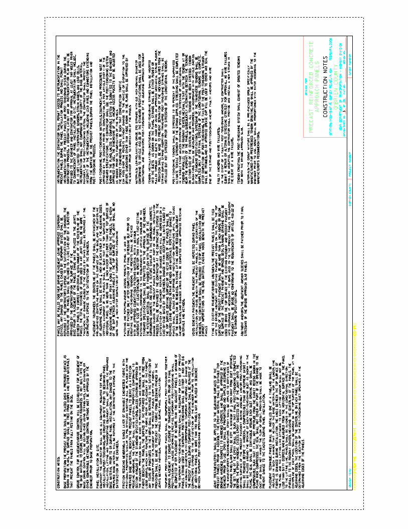
CO
UN
TY
DE
SIG
N S
HE
ET
NO
.O
FD
ES
IGN
NO
.F
ILE
NO
.
IOW
A D
EP
AR
TM
EN
T O
F T
RA
NS
PO
RT
AT
ION
- H
IGH
WA
Y D
IVIS
ION
PR
OJE
CT
NU
MB
ER
SH
EE
T N
UM
BE
R
XX
XX
XX
XX
XX
SY
ST
EM
TIM
EX
XX
XX
XX
US
ER
NA
ME
XX
XX
XX
XX
XX
XX
XX
XX
XX
XX
XX
XX
XX
XX
XX
XX
XX
XX
XX
XX
XX
XX
XX
XX
XX
XX
XD
GN
SP
EC
DE
SIG
N T
EA
M
20
O’B
RIE
N
O’B
RIE
N C
OU
NT
Y
DE
SIG
N F
OR
PR
EC
AS
T R
EIN
FO
RC
ED
CO
NC
RE
TE
ST
AT
IO
N:
14
29
+1
6.6
7 (
| S
UR
VE
Y R
EL
OC
. IA
. 6
0)
F
EB
RU
AR
Y,
20
06
AP
PR
OA
CH
PA
NE
LS
BA
SE
PR
EP
AR
AT
ION
: T
HE
PR
EC
AS
T P
AN
EL
S S
HA
LL
BE
PL
AC
ED
OV
ER
A P
RE
PA
RE
D S
UR
FA
CE
AS
SH
OW
N I
N T
HE
PL
AN
S. T
HE
SU
RF
AC
E S
HA
LL
BE
FR
EE
FR
OM
DE
BR
IS A
ND
OT
HE
R M
AT
ER
IAL
S
TH
AT
PR
EV
EN
T T
HE
PA
NE
LS
FR
OM
FU
LL
Y R
ES
TIN
G O
N T
HE
BA
SE
.
GR
AD
E C
ON
TR
OL
FO
R P
LA
CE
ME
NT
: G
RA
DE
CO
NT
RO
L W
ILL
BE
ES
TA
BL
ISH
ED
FO
R P
LA
CE
ME
NT
OF
TH
E B
AS
E M
AT
ER
IAL
TO
EN
SU
RE
LO
NG
-WA
VE
LE
NG
TH
RO
UG
HN
ES
S I
S N
OT
BU
ILT
IN
TO
TH
E
BA
SE
. G
RA
DE
CO
NT
RO
L W
ILL
BE
ES
TA
BL
ISH
ED
US
ING
ST
RIN
GL
INE
S,
LA
SE
R G
UID
AN
CE
, O
R
OT
HE
R C
OM
PA
RA
BL
E M
ET
HO
DS
. G
RA
DE
CO
NT
RO
L M
ET
HO
DS
MU
ST
BE
AP
PR
OV
ED
BY
TH
E
EN
GIN
EE
R P
RIO
R T
O B
AS
E P
RE
PA
RA
TIO
N.
PA
NE
L I
NS
TA
LL
AT
ION
ON
SIT
E:
EQ
UIP
ME
NT
: T
HE
CO
NT
RA
CT
OR
SH
AL
L H
AV
E A
LL
EQ
UIP
ME
NT
RE
QU
IRE
D F
OR
PA
NE
L
INS
TA
LL
AT
ION
, P
OS
T-T
EN
SIO
NIN
G, A
ND
GR
OU
TIN
G O
N-S
ITE
PR
IOR
TO
BE
GIN
NIN
G P
AN
EL
INS
TA
LL
AT
ION
. L
IFT
ING
AN
D T
RA
NS
PO
RT
ING
EQ
UIP
ME
NT
SH
AL
L N
OT
DA
MA
GE
TH
E P
RE
PA
RE
D
BA
SE
MA
TE
RIA
L P
RIO
R T
O O
R D
UR
ING
PA
NE
L I
NS
TA
LL
AT
ION
. A
NY
DA
MA
GE
TO
TH
E
PR
EP
AR
ED
BA
SE
MA
TE
RIA
L W
ILL
BE
RE
PA
IRE
D A
T T
HE
CO
NT
RA
CT
OR
’S E
XP
EN
SE
TO
TH
E
SA
TIS
FA
CT
ION
OF
TH
E E
NG
INE
ER
.
FR
ICT
ION
RE
DU
CIN
G M
EM
BR
AN
E:
A S
ING
LE
LA
YE
R O
F D
RA
INA
BL
E E
NG
INE
ER
ED
FA
BR
IC W
ITH
FR
ICT
ION
AL
PR
OP
ER
TIE
S S
IMIL
AR
TO
PO
LY
ET
HY
LE
NE
SH
EE
TIN
G W
ILL
BE
PL
AC
ED
OV
ER
TH
E
PR
EP
AR
ED
BA
SE
MA
TE
RIA
L, B
EN
EA
TH
TH
E P
RE
CA
ST
PA
NE
LS
, T
O S
ER
VE
AS
A F
RIC
TIO
N
RE
DU
CIN
G M
EM
BR
AN
E. T
HE
FA
BR
IC S
HA
LL
HA
VE
MA
TE
RIA
L P
RO
PE
RT
IES
CO
NF
OR
MIN
G T
O
SE
CT
ION
41
96
.01
B O
F T
HE
ST
AN
DA
RD
SP
EC
IFIC
AT
ION
S,
UN
LE
SS
OT
HE
RW
ISE
AP
PR
OV
ED
BY
TH
E E
NG
INE
ER
. P
RO
VIS
ION
SH
AL
L B
E M
AD
E T
O P
RE
VE
NT
FO
LD
S A
ND
CR
EA
SE
S I
N T
HE
FA
BR
IC B
EN
EA
TH
TH
E P
AN
EL
S. T
HE
SU
RF
AC
E O
F T
HE
PR
EP
AR
ED
BA
SE
SH
AL
L B
E F
RE
E F
RO
M
LO
OS
E D
EB
RIS
, W
HIC
H M
AY
PU
NC
TU
RE
TH
E F
AB
RIC
PR
IOR
TO
PL
AC
EM
EN
T O
F T
HE
FA
BR
IC.
AN
Y T
EA
RS
OR
PU
NC
TU
RE
S I
N T
HE
FA
BR
IC S
HA
LL
BE
RE
PA
IRE
D T
O T
HE
SA
TIS
FA
CT
ION
OF
TH
E E
NG
INE
ER
PR
IOR
TO
PL
AC
EM
EN
T O
F T
HE
PR
EC
AS
T P
AN
EL
S O
VE
R T
HE
FA
BR
IC.
PR
OV
ISIO
N S
HA
LL
BE
MA
DE
TO
PR
EV
EN
T T
HE
FA
BR
IC F
RO
M B
EC
OM
ING
PIN
CH
ED
IN
TH
E
JO
INT
S B
ET
WE
EN
IN
DIV
IDU
AL
PR
EC
AS
T P
AN
EL
S D
UR
ING
PA
NE
L I
NS
TA
LL
AT
ION
.
TE
MP
OR
AR
Y P
OS
T-T
EN
SIO
NIN
G:
PA
NE
LS
SH
AL
L B
E T
EM
PO
RA
RIL
Y P
OS
T-T
EN
SIO
NE
D T
OG
ET
HE
R
DU
RIN
G P
LA
CE
ME
NT
TO
EN
SU
RE
CL
OS
UR
E O
F T
RA
NS
VE
RS
E J
OIN
TS
PR
IOR
TO
FIN
AL
PO
ST
-TE
NS
ION
ING
. U
NL
ES
S O
TH
ER
WIS
E S
PE
CIF
IED
, T
EM
PO
RA
RY
PO
ST
-TE
NS
ION
ING
SH
AL
L
INC
H N
OM
INA
L D
IAM
ET
ER
, W
ITH
CO
RR
ES
PO
ND
ING
TE
MP
OR
AR
Y A
NC
HO
RA
GE
. A
NY
DA
MA
GE
TO
TH
E P
RE
CA
ST
PA
NE
LS
DU
RIN
G T
EM
PO
RA
RY
PO
ST
-TE
NS
ION
ING
SH
AL
L B
E R
EP
AIR
ED
AT
TH
E
CO
NT
RA
CT
OR
’S E
XP
EN
SE
TO
TH
E S
AT
ISF
AC
TIO
N O
F T
HE
EN
GIN
EE
R P
RIO
R T
O I
NS
TA
LL
AT
ION
OF
AD
DIT
ION
AL
PA
NE
LS
. N
O M
OR
E T
HA
N T
WO
PA
NE
LS
MA
Y B
E P
LA
CE
D I
N S
EQ
UE
NC
E
BE
TW
EE
N T
EM
PO
RA
RY
PO
ST
-TE
NS
ION
ING
OP
ER
AT
ION
S.
JO
INT
TR
EA
TM
EN
T:
EP
OX
Y S
HA
LL
BE
AP
PL
IED
TO
TH
E A
DJO
ININ
G S
UR
FA
CE
S O
F T
HE
PR
EC
AS
T P
AN
EL
S P
RIO
R T
O A
SS
EM
BL
Y.
TH
E E
PO
XY
MA
TE
RIA
L S
HA
LL
BE
SU
ITA
BL
E F
OR
BO
ND
ING
HA
RD
EN
ED
CO
NC
RE
TE
TO
HA
RD
EN
ED
CO
NC
RE
TE
AN
D S
HA
LL
BE
AP
PR
OV
ED
BY
TH
E
EN
GIN
EE
R P
RIO
R T
O U
SE
. E
PO
XY
SH
AL
L B
E P
RO
PO
RT
ION
ED
AN
D A
PP
LIE
D A
CC
OR
DIN
G T
O
TH
E M
AN
UF
AC
TU
RE
R’S
RE
CO
MM
EN
DA
TIO
NS
. E
PO
XY
SH
AL
L B
E A
PP
LIE
D T
O B
OT
H F
AC
ES
OF
TH
E S
ET
TIM
E O
F T
HE
EP
OX
Y S
HA
LL
BE
SU
CH
TH
AT
FIN
AL
PO
ST
-TE
NS
ION
ING
IS
CO
MP
LE
TE
D
BE
FO
RE
TH
E E
PO
XY
HA
RD
EN
S.
EX
CE
SS
EP
OX
Y S
QU
EE
ZE
D O
UT
OF
TH
E J
OIN
T O
NT
O T
HE
DR
IVIN
G S
UR
FA
CE
OF
TH
E P
RE
CA
ST
PA
VE
ME
NT
DU
RIN
G A
SS
EM
BL
Y A
ND
/OR
PO
ST
-TE
NS
ION
ING
SH
AL
L B
E R
EM
OV
ED
BE
FO
RE
IT
HA
RD
EN
S. A
CO
MP
RE
SS
IBL
E F
OA
M O
R N
EO
PR
EN
E G
AS
KE
T
SH
AL
L B
E P
LA
CE
D A
RO
UN
D T
HE
OP
EN
ING
OF
EA
CH
PO
ST
-TE
NS
ION
ING
DU
CT
AS
SH
OW
N I
N T
HE
PL
AN
S. T
HE
SE
AL
SH
AL
L B
E C
ON
TIN
UO
US
AR
OU
ND
EA
CH
DU
CT
OP
EN
ING
AN
D S
HA
LL
BE
CO
MP
RE
SS
IBL
E S
UC
H T
HA
T I
T W
ILL
NO
T P
RO
TR
UD
E F
RO
M T
HE
GA
SK
ET
RE
CE
SS
SH
OW
N I
N T
HE
PL
AN
S W
HE
N C
OM
PR
ES
SE
D.
TH
E S
EA
L S
HA
LL
NO
T C
OV
ER
AN
Y P
AR
T O
F T
HE
OP
EN
ING
TO
TH
E
DU
CT
AN
D S
HA
LL
NO
T I
NH
IBIT
TH
E F
LO
W O
F G
RO
UT
. P
RO
VIS
ION
SH
AL
L B
E M
AD
E T
O
PR
EV
EN
T D
AM
AG
E T
O T
HE
GA
SK
ET
S D
UR
ING
PA
NE
L I
NS
TA
LL
AT
ION
.
PL
AC
EM
EN
T T
EC
HN
IQU
E:
PA
NE
LS
SH
AL
L B
E I
NS
TA
LL
ED
ON
E A
T A
TIM
E, A
ND
SH
AL
L B
E
INS
TA
LL
ED
IN
SU
CH
A M
AN
NE
R T
HA
T N
EIT
HE
R T
HE
BA
SE
MA
TE
RIA
L N
OR
TH
E U
ND
ER
LY
ING
FA
BR
IC I
S D
AM
AG
ED
DU
RIN
G I
NS
TA
LL
AT
ION
. T
HE
AN
GL
E B
ET
WE
EN
TH
E T
OP
SU
RF
AC
E O
F
TH
E P
AN
EL
AN
D T
HE
LIF
TIN
G L
INE
AT
TA
CH
ED
TO
EA
CH
LIF
TIN
G A
NC
HO
R S
HA
LL
NO
T B
E
LE
SS
TH
AN
SIX
TY
DE
GR
EE
S,
WH
EN
ME
AS
UR
ED
FR
OM
TH
E H
OR
IZO
NT
AL
SU
RF
AC
E O
F T
HE
PA
NE
L
TO
TH
E L
IFT
ING
LIN
E. P
AN
EL
S S
HA
LL
BE
AL
IGN
ED
IN
TH
E L
ON
GIT
UD
INA
L D
IRE
CT
ION
(PA
RA
LL
EL
TO
TH
E R
OA
DW
AY
CE
NT
ER
LIN
E)
US
ING
TH
E C
EN
TE
RL
INE
OF
TH
E P
AN
EL
S.
TH
E
CE
NT
ER
LIN
E O
F E
AC
H P
AN
EL
SH
AL
L B
E M
AR
KE
D O
N T
HE
TO
P S
UR
FA
CE
OF
TH
E P
AN
EL
AT
TH
E
AD
JO
ININ
G E
DG
ES
. T
HE
LO
CA
TIO
N O
F T
HE
CE
NT
ER
LIN
E O
N E
AC
H P
AN
EL
SH
AL
L B
E
DE
TE
RM
INE
D F
RO
M T
HE
LO
CA
TIO
N O
F T
HE
PO
ST
-TE
NS
ION
ING
DU
CT
OP
EN
ING
S A
T T
HE
AD
JO
ININ
G E
DG
ES
OF
TH
E P
AN
EL
S.
PA
NE
LS
MA
Y B
E P
UL
LE
D T
OG
ET
HE
R D
UR
ING
PL
AC
EM
EN
T U
SIN
G A
PP
RO
VE
D T
EM
PO
RA
RY
DE
VIC
ES
. A
NY
DA
MA
GE
TO
TH
E P
AN
EL
S C
AU
SE
D B
Y T
EM
PO
RA
RY
DE
VIC
ES
SH
AL
L B
E
RE
PA
IRE
D A
T T
HE
CO
NT
RA
CT
OR
’S E
XP
EN
SE
TO
TH
E S
AT
ISF
AC
TIO
N O
F T
HE
EN
GIN
EE
R. T
HE
CE
NT
ER
LIN
E O
F T
HE
PA
NE
LS
SH
AL
L B
E A
LIG
NE
D T
O A
LIN
E L
AID
OU
T B
Y A
SU
RV
EY
OR
(PR
OV
IDE
D B
Y T
HE
CO
NT
RA
CT
OR
) O
N T
HE
SU
RF
AC
E O
F T
HE
BA
SE
PR
IOR
TO
PL
AC
EM
EN
T O
F T
HE
PA
NE
LS
. S
HIM
S M
AY
BE
PL
AC
ED
IN
TH
E J
OIN
TS
BE
TW
EE
N P
AN
EL
S T
O C
OR
RE
CT
HO
RIZ
ON
TA
L M
ISA
LIG
NM
EN
T O
F T
HE
CE
NT
ER
LIN
E O
F T
HE
PA
NE
LS
. T
HE
TO
TA
L T
HIC
KN
ES
S O
F S
HIM
S U
SE
D I
N A
NY
JO
INT
SH
AL
L B
E N
O M
OR
E
TH
AN
1/8
IN
CH
. A
NY
DA
MA
GE
CA
US
ED
TO
TH
E P
AN
EL
S B
Y S
HIM
S S
HA
LL
BE
RE
PA
IRE
D A
T T
HE
CO
NT
RA
CT
OR
’S E
XP
EN
SE
TO
TH
E S
AT
ISF
AC
TIO
N O
F T
HE
EN
GIN
EE
R.
PL
AC
EM
EN
T T
OL
ER
AN
CE
S:
TH
E C
EN
TE
RL
INE
OF
TH
E P
AN
EL
S S
HA
LL
BE
WIT
HIN
1/4
IN
CH
OF
TH
E
PR
E-S
UR
VE
YE
D C
EN
TE
RL
INE
MA
RK
ED
ON
TH
E S
UR
FA
CE
OF
TH
E B
AS
E, A
ND
TH
E C
EN
TE
RL
INE
VE
RT
ICA
L A
LIG
NM
EN
T O
F T
HE
PA
NE
LS
SH
AL
L B
E S
UC
H T
HA
T T
HE
TO
P S
UR
FA
CE
OF
AN
AN
AD
JO
ININ
G P
AN
EL
AT
AN
Y P
OIN
T A
LO
NG
TH
E J
OIN
T B
ET
WE
EN
TH
E P
AN
EL
S. T
HE
WID
TH
OF
TH
E G
AP
BE
TW
EE
N A
DJO
ININ
G P
AN
EL
S A
T T
HE
TO
P S
UR
FA
CE
OF
TH
E J
OIN
T S
HA
LL
BE
NO
AG
GR
EG
AT
E S
IZE
OF
AT
LE
AS
T 3
/8 I
NC
H,
BU
T N
O G
RE
AT
ER
TH
AN
1 I
NC
H.
A F
AS
T-S
ET
TIN
G
PA
TC
HIN
G M
AT
ER
IAL
, C
ON
FO
RM
ING
TO
TH
E R
EQ
UIR
EM
EN
TS
OF
AR
TIC
LE
2529.0
2B
OF
TH
E
ST
AN
DA
RD
SP
EC
IFIC
AT
ION
S,
SH
AL
L B
E P
ER
MIT
TE
D W
ITH
TH
E A
PP
RO
VA
L O
F T
HE
EN
GIN
EE
R.
TH
E P
AT
CH
ING
MA
TE
RIA
L S
HA
LL
BE
FIN
ISH
ED
FL
US
H W
ITH
TH
E S
UR
FA
CE
OF
TH
E
SU
RR
OU
ND
ING
CO
NC
RE
TE
AN
D G
IVE
N A
TE
XT
UR
E S
IMIL
AR
TO
TH
E S
UR
RO
UN
DIN
G C
ON
CR
ET
E.
DA
MA
GE
CA
US
ED
TO
TH
E P
RE
CA
ST
PA
NE
LS
DU
RIN
G A
NY
PA
RT
OF
TH
E P
AN
EL
IN
ST
AL
LA
TIO
N
PR
OC
ES
S S
HA
LL
BE
RE
PA
IRE
D B
Y T
HE
CO
NT
RA
CT
OR
AT
TH
E C
ON
TR
AC
TO
R’S
EX
PE
NS
E T
O T
HE
SA
TIS
FA
CT
ION
OF
TH
E E
NG
INE
ER
. R
EP
AIR
S O
F D
AM
AG
ED
AR
EA
S W
ILL
BE
AD
DR
ES
SE
D O
N A
CA
SE
-BY
-CA
SE
BA
SIS
BY
TH
E E
NG
INE
ER
. D
AM
AG
E W
ITH
IN A
CC
EP
TA
BL
E L
IMIT
S C
AU
SE
D T
O
TH
E T
OP
SU
RF
AC
E (
DR
IVIN
G S
UR
FA
CE
) O
R T
O K
EY
ED
ED
GE
S O
F T
HE
PA
NE
LS
SH
AL
L B
E
RE
PA
IRE
D U
SIN
G A
PP
RO
VE
D R
EP
AIR
ME
TH
OD
S A
ND
MA
TE
RIA
LS
. R
EP
ET
ITIV
E D
AM
AG
E T
O
PA
NE
LS
SH
AL
L B
E C
AU
SE
FO
R S
TO
PP
AG
E O
F I
NS
TA
LL
AT
ION
OP
ER
AT
ION
S U
NT
IL T
HE
CA
US
E
OF
TH
E D
AM
AG
E C
AN
BE
RE
ME
DIE
D. P
AT
CH
ING
LIF
TIN
G A
NC
HO
R R
EC
ES
SE
S, A
BU
TM
EN
T
AN
CH
OR
SL
EE
VE
S,
AN
D D
AM
AG
ED
AR
EA
S S
HA
LL
BE
CO
MP
LE
TE
D U
SIN
G A
PP
RO
VE
D P
AT
CH
ING
MA
TE
RIA
LS
AN
D M
ET
HO
DS
.
VO
IDS
BE
NE
AT
H P
AV
EM
EN
T:
TH
E P
AV
EM
EN
T S
HA
LL
BE
IN
SP
EC
TE
D D
UR
ING
PA
NE
L
INS
TA
LL
AT
ION
FO
R V
OID
S B
EN
EA
TH
TH
E P
RE
CA
ST
PA
NE
LS
. A
T T
HE
DIS
CR
ET
ION
OF
TH
E
EN
GIN
EE
R, T
HE
CO
NT
RA
CT
OR
SH
AL
L B
E R
EQ
UIR
ED
TO
ST
OP
PA
NE
L I
NS
TA
LL
AT
ION
AN
D
CO
RR
EC
T I
MP
ER
FE
CT
ION
S I
N T
HE
BA
SE
MA
TE
RIA
L C
AU
SIN
G V
OID
S B
EN
EA
TH
TH
E P
RE
CA
ST
PA
NE
LS
.
TY
ING
TO
EX
IST
ING
PA
VE
ME
NT
/BR
IDG
E A
BU
TM
EN
T:
TH
E P
RE
CA
ST
PA
NE
LS
SH
AL
L B
E T
IED
INT
O T
HE
BR
IDG
E A
BU
TM
EN
T A
ND
EX
IST
ING
PA
VE
ME
NT
AS
SH
OW
N O
N T
HE
PL
AN
S. T
HE
TO
P
PA
VE
ME
NT
SH
AL
L B
E G
RA
DE
60
CO
NF
OR
MIN
G T
O T
HE
RE
QU
IRE
ME
NT
S O
F A
RT
ICL
E 4
15
1.0
2 O
F
TH
E S
TA
ND
AR
D S
PE
CIF
ICA
TIO
NS
.
AB
UT
ME
NT
AN
CH
OR
S:
TH
E A
BU
TM
EN
T A
NC
HO
R S
LE
EV
ES
SH
AL
L B
E P
AT
CH
ED
PR
IOR
TO
FIN
AL
ST
RE
SS
ING
OF
TH
E B
RID
GE
AP
PR
OA
CH
SL
AB
PA
NE
LS
.
INS
TR
UM
EN
TA
TIO
N:
TH
E C
ON
TR
AC
TO
R S
HA
LL
PE
RM
IT A
CC
ES
S T
O I
NS
TR
UM
EN
TA
TIO
N I
N T
HE
PR
EC
AS
T P
AN
EL
S D
UR
ING
TH
E P
AN
EL
IN
ST
AL
LA
TIO
N P
RO
CE
SS
AN
D S
HA
LL
PE
RM
IT
INS
TR
UM
EN
TA
TIO
N O
F T
HE
PR
EC
AS
T P
AN
EL
S A
ND
PO
ST
-TE
NS
ION
ING
SY
ST
EM
DU
RIN
G T
HE
CO
NS
TR
UC
TIO
N P
RO
CE
SS
. A
SC
HE
MA
TIC
LA
YO
UT
AN
D A
N I
NS
TR
UM
EN
TA
TIO
N P
LA
N S
HA
LL
BE
PR
OV
IDE
D T
O T
HE
EN
GIN
EE
R A
ND
CO
NT
RA
CT
OR
FO
R A
PP
RO
VA
L A
T L
EA
ST
TW
O W
EE
KS
PR
IOR
TO
CO
MM
EN
CE
ME
NT
OF
PA
NE
L I
NS
TA
LL
AT
ION
ON
SIT
E.
IN
ST
RU
ME
NT
AT
ION
SH
AL
L I
NC
LU
DE
,
BU
T I
S N
OT
LIM
ITE
D T
O,
TE
MP
ER
AT
UR
E S
EN
SO
RS
, S
TR
AIN
GA
GE
S,
AN
D L
OA
D C
EL
LS
.
INS
TR
UM
EN
TA
TIO
N S
HA
LL
NO
T C
OM
PR
OM
ISE
TH
E I
NT
EG
RIT
Y O
F T
HE
BA
SE
MA
TE
RIA
L,
PA
VE
ME
NT
, O
R T
HE
PO
ST
-TE
NS
ION
ING
SY
ST
EM
. T
HE
CO
NT
RA
CT
OR
SH
AL
L P
RO
TE
CT
TH
E
INT
EG
RIT
Y O
F T
HE
IN
ST
RU
ME
NT
AT
ION
, IN
CL
UD
ING
LE
AD
WIR
ES
AN
D C
ON
NE
CT
OR
S E
XT
EN
DIN
G
FR
OM
TH
E S
UR
FA
CE
OF
TH
E P
RE
CA
ST
PA
NE
LS
, D
UR
ING
TH
E P
AN
EL
IN
ST
AL
LA
TIO
N A
ND
PO
ST
-TE
NS
ION
ING
PR
OC
ES
S.
PO
ST
-TE
NS
ION
ING
: P
OS
T-T
EN
SIO
NIN
G M
AT
ER
IAL
S,
EQ
UIP
ME
NT
, A
ND
PR
OC
ED
UR
ES
MU
ST
BE
AP
PR
OV
ED
BY
TH
E E
NG
INE
ER
PR
IOR
TO
CO
NS
TR
UC
TIO
N, A
S P
ER
AR
TIC
LE
2407.1
1 O
F T
HE
ST
AN
DA
RD
SP
EC
IFIC
AT
ION
S. T
HE
CO
NT
RA
CT
OR
SH
AL
L U
SE
TH
E P
OS
T-T
EN
SIO
NIN
G S
YS
TE
M
SH
OW
N I
N T
HE
PL
AN
S, U
NL
ES
S A
CO
MP
AR
AB
LE
SY
ST
EM
IS
SU
BM
ITT
ED
TO
TH
E E
NG
INE
ER
AN
D
AP
PR
OV
ED
FO
R U
SE
. T
HE
DIM
EN
SIO
NS
OF
TH
E A
NC
HO
R A
CC
ES
S P
OC
KE
TS
MA
Y B
E A
DJU
ST
ED
CA
N P
AS
S O
VE
R T
HE
PO
CK
ET
S W
ITH
OU
T D
AM
AG
E T
O T
HE
VE
HIC
LE
OR
DIS
RU
PT
ION
TO
TH
E
DR
IVE
R.
DIM
EN
SIO
NS
OT
HE
R T
HA
N T
HO
SE
SH
OW
N I
N T
HE
PL
AN
S S
HA
LL
BE
AP
PR
OV
ED
BY
MA
TE
RIA
LS
: L
OW
-RE
LA
XA
TIO
N,
GR
AD
E 2
70
ST
RA
ND
S W
ITH
0.6
IN
CH
NO
MIN
AL
DIA
ME
TE
R
CO
NF
OR
MIN
G T
O A
RT
ICL
E 4
151.0
5 O
F T
HE
ST
AN
DA
RD
SP
EC
IFIC
AT
ION
S, S
HA
LL
BE
US
ED
FO
R
LO
NG
ITU
DIN
AL
AN
D T
RA
NS
VE
RS
E P
OS
T-T
EN
SIO
NIN
G O
F T
HE
AD
JO
ININ
G A
PP
RO
AC
H P
AV
EM
EN
T.
TE
ND
ON
IN
ST
AL
LA
TIO
N:
LO
NG
ITU
DIN
AL
PO
ST
-TE
NS
ION
ING
ST
RA
ND
S S
HA
LL
BE
IN
SE
RT
ED
INT
O T
HE
DU
CT
S A
S S
HO
WN
ON
TH
E P
LA
NS
. S
TR
AN
DS
SH
AL
L B
E E
ITH
ER
PU
SH
ED
OR
PU
LL
ED
TH
RO
UG
H T
HE
DU
CT
S B
Y H
AN
D O
R U
SIN
G A
N A
PP
RO
VE
D M
EC
HA
NIC
AL
ST
RA
ND
PU
SH
ER
.
PR
OV
ISIO
N S
HA
LL
BE
MA
DE
TO
PR
EV
EN
T S
EP
AR
AT
ION
OF
TH
E I
ND
IVID
UA
L W
IRE
S F
RO
M T
HE
ST
RA
ND
DU
RIN
G S
TR
AN
D I
NS
ER
TIO
N. T
RA
NS
VE
RS
E P
OS
T-T
EN
SIO
NIN
G S
TR
AN
DS
SH
AL
L B
E
INS
TA
LL
ED
BU
T N
OT
ST
RE
SS
ED
PR
IOR
TO
ST
RE
SS
ING
OF
TH
E L
ON
GIT
UD
INA
L T
EN
DO
NS
.
PO
ST
-TE
NS
ION
ING
TE
ND
ON
S S
HA
LL
BE
ST
RE
SS
ED
TO
75 P
ER
CE
NT
OF
TH
E G
UA
RA
NT
EE
D
UL
TIM
AT
E T
EN
SIL
E S
TR
EN
GT
H O
F T
HE
ST
RA
ND
SU
PP
LIE
D.
ST
RE
SS
ING
SH
AL
L B
E C
OM
PL
ET
ED
IN A
SIN
GL
E S
TA
GE
UN
LE
SS
OT
HE
RW
ISE
SP
EC
IFIE
D. S
TR
ES
SIN
G O
F L
ON
GIT
UD
INA
L
TE
ND
ON
S (
PA
RA
LL
EL
TO
TH
E R
OA
DW
AY
CE
NT
ER
LIN
E)
SH
AL
L S
TA
RT
WIT
H T
HE
TE
ND
ON
AT
OR
NE
AR
TH
E M
IDP
OIN
T O
F T
HE
PA
NE
LS
, S
UB
SE
QU
EN
TL
Y A
LT
ER
NA
TIN
G B
ET
WE
EN
TH
E T
EN
DO
NS
ON
EIT
HE
R S
IDE
OF
TH
E C
EN
TE
RL
INE
UN
TIL
AL
L T
EN
DO
NS
HA
VE
BE
EN
ST
RE
SS
ED
. T
EN
DO
N
EL
ON
GA
TIO
NS
SH
AL
L B
E M
EA
SU
RE
D A
ND
RE
CO
RD
ED
, IN
AC
CO
RD
AN
CE
WIT
H A
RT
ICL
E 2
407.0
6
OF
TH
E S
TA
ND
AR
D S
PE
CIF
ICA
TIO
NS
. S
TR
ES
SIN
G O
F T
HE
TR
AN
SV
ER
SE
TE
ND
ON
S S
HA
LL
BE
CO
MP
LE
TE
D O
NL
Y A
FT
ER
FIN
AL
ST
RE
SS
ING
OF
TH
E L
ON
GIT
UD
INA
L T
EN
DO
NS
IS
CO
MP
LE
TE
.
AF
TE
R C
OM
PL
ET
ION
OF
PO
ST
-TE
NS
ION
ING
, T
HE
TA
ILS
OF
TH
E P
OS
T-T
EN
SIO
NIN
G S
TR
AN
DS
SH
AL
L B
E T
RIM
ME
D, A
ND
AN
AP
PR
OV
ED
GR
EA
SE
CA
P W
ILL
BE
US
ED
TO
CO
VE
R A
ND
SE
AL
TH
E
EN
D O
F T
HE
ST
RA
ND
AN
D P
OS
T-T
EN
SIO
NIN
G A
NC
HO
R. F
AU
LT
Y A
NC
HO
RS
AN
D W
IRE
SU
BM
IT A
RE
PA
IR O
R A
LT
ER
NA
TE
ST
RE
SS
ING
ST
RA
TE
GY
FO
R A
PP
RO
VA
L. N
O W
IRE
FA
ILU
RE
S
SH
AL
L B
E A
CC
EP
TE
D.
TH
E C
ON
TR
AC
TO
R S
HA
LL
PR
OV
IDE
AN
D I
NS
TA
LL
A N
EW
ST
RA
ND
IN
TH
E E
VE
NT
OF
A W
IRE
FA
ILU
RE
.
TE
ND
ON
GR
OU
TIN
G:
TH
E P
OS
T-T
EN
SIO
NIN
G S
YS
TE
M S
HA
LL
CO
NS
IST
OF
GR
OU
TE
D T
EN
DO
NS
FO
R B
OT
H T
HE
BR
IDG
E A
PP
RO
AC
H S
LA
B.
MA
TE
RIA
LS
: T
HE
GR
OU
T M
IXT
UR
E S
HA
LL
BE
A P
RE
-PA
CK
AG
ED
GR
OU
T S
PE
CIF
ICA
LL
Y
MA
NU
FA
CT
UR
ED
FO
R P
RE
ST
RE
SS
ED
TE
ND
ON
GR
OU
TIN
G, A
ND
SH
AL
L B
E A
PP
RO
VE
D B
Y T
HE
EN
GIN
EE
R P
RIO
R T
O U
SE
. G
RO
UT
SH
AL
L B
E P
RO
PO
RT
ION
ED
WIT
H W
AT
ER
AC
CO
RD
ING
TO
TH
E
MA
NU
FA
CT
UR
ER
’S R
EC
OM
ME
ND
AT
ION
S.
CO
NS
TR
UC
TIO
N N
OT
ES
:
CO
NS
TR
UC
TIO
N N
OT
ES
PA
NE
LS
. S
TR
AN
D U
SE
D F
OR
TE
MP
OR
AR
Y P
OS
T-T
EN
SIO
NIN
G S
HA
LL
BE
EIT
HE
R
1/2
IN
CH
OR
0.6
AD
JO
ININ
G P
AN
EL
S, A
ND
SH
AL
L B
E K
EP
T A
MIN
IMU
M O
F 1/2
IN
CH
AW
AY
FR
OM
DU
CT
OP
EN
ING
S.
IND
IVID
UA
L P
AN
EL
IS
NO
MO
RE
TH
AN
3/1
6 IN
CH
HIG
HE
R O
R L
OW
ER
TH
AN
TH
E T
OP
SU
RF
AC
E O
F
OF
AD
JO
ININ
G P
AN
EL
S S
HA
LL
BE
WIT
HIN
1
/8
INC
H O
F E
AC
H O
TH
ER
AT
TH
E A
DJO
ININ
G E
DG
ES
.
MO
RE
TH
AN
1
/8
INC
H A
FT
ER
CO
MP
LE
TIO
N O
F T
EM
PO
RA
RY
PO
ST
-TE
NS
ION
ING
.
TH
E S
UR
FA
CE
OF
TH
E P
RE
CA
ST
PA
VE
ME
NT
AN
D B
RID
GE
DE
CK
. D
IAM
ON
D G
RIN
DIN
G S
HA
LL
BE
SU
RF
AC
E O
F T
HE
PR
EC
AS
T P
AV
EM
EN
T S
HA
LL
BE
NO
MO
RE
TH
AN
1
/4
INC
H A
BO
VE
OR
BE
LO
W
INT
O T
OL
ER
AN
CE
IF
NE
CE
SS
AR
Y. T
IE B
AR
S U
SE
D T
O T
IE T
HE
PR
EC
AS
T P
AN
EL
S T
O A
DJA
CE
NT
US
ED
TO
BR
ING
TH
E T
OP
SU
RF
AC
E O
F T
HE
EX
IST
ING
PA
VE
ME
NT
AN
D P
RE
CA
ST
PA
VE
ME
NT
3
GR
OU
TIN
G T
HE
PO
ST
-TE
NS
ION
ING
TE
ND
ON
S.
TH
E P
OC
KE
TS
SH
AL
L B
E P
AT
CH
ED
WIT
H A
N A
PP
RO
VE
D C
EM
EN
TIT
IOU
S P
AT
CH
ING
MA
TE
RIA
L W
ITH
A M
AX
IMU
M
AS
NE
ED
ED
PR
IOR
TO
FA
BR
ICA
TIO
N O
F T
HE
PA
NE
LS
.
TH
E P
OC
KE
T D
IME
NS
ION
S S
HA
LL
BE
SU
CH
TH
AT
CO
NS
TR
UC
TIO
N T
RA
FF
IC
TH
E E
NG
INE
ER
PR
IOR
TO
FA
BR
ICA
TIO
N O
F T
HE
PA
NE
LS
.
BE
CO
MP
LE
TE
D A
FT
ER
PL
AC
EM
EN
T O
F N
O M
OR
E T
HA
N T
WO
AD
JA
CE
NT
PA
NE
LS
. A
MIN
IMU
M O
F
TW
O T
EM
PO
RA
RY
PO
ST
-TE
NS
ION
ING
ST
RA
ND
S S
HA
LL
BE
RE
QU
IRE
D F
OR
EA
CH
SE
T O
F P
RE
CA
ST
PA
TC
HIN
G A
ND
RE
PA
IRS
: A
NC
HO
R A
CC
ES
S P
OC
KE
TS
(P
AN
EL
1A
AN
D 1
B)
SH
AL
L B
E P
AT
CH
ED
ON
LY
AF
TE
R C
OM
PL
ET
ION
OF
FIN
AL
ST
RE
SS
ING
BU
T P
RIO
R T
O
IN T
HE
EV
EN
T O
F A
FA
UL
TY
PO
ST
-TE
NS
ION
ING
AN
CH
OR
, T
HE
CO
NT
RA
CT
OR
SH
AL
L
FA
UL
TY
AN
CH
OR
S A
ND
WIR
E F
AIL
UIR
ES
:

CO
UN
TY
DE
SIG
N S
HE
ET
NO
.O
FD
ES
IGN
NO
.F
ILE
NO
.
IOW
A D
EP
AR
TM
EN
T O
F T
RA
NS
PO
RT
AT
ION
- HIG
HW
AY
DIV
ISIO
N
PR
OJE
CT
NU
MB
ER
SH
EE
T N
UM
BE
R
XX
XX
XX
XX
XX
SY
ST
EM
TIM
EX
XX
XX
XX
US
ER
NA
ME
XX
XX
XX
XX
XX
XX
XX
XX
XX
XX
XX
XX
XX
XX
XX
XX
XX
XX
XX
XX
XX
XX
XX
XX
XX
XX
XD
GN
SP
EC
DE
SIG
N T
EA
M
20
O’B
RIE
N
O’B
RIE
N C
OU
NT
Y
DE
SIG
N F
OR
PR
EC
AS
T R
EIN
FO
RC
ED
CO
NC
RE
TE
ST
AT
IO
N: 1
429+
16.6
7 (
| SU
RV
EY
RE
LO
C. I
A. 6
0) F
EB
RU
AR
Y, 2
006
AP
PR
OA
CH
PA
NE
LS
EQ
UIP
ME
NT
: GR
OU
TIN
G E
QU
IPM
EN
T S
HA
LL
CO
NS
IST
OF
AT
LE
AS
T T
HE
FO
LL
OW
ING
:
- EQ
UIP
ME
NT
FO
R A
CC
UR
AT
EL
Y M
EA
SU
RIN
G A
ND
PR
OP
OR
TIO
NIN
G B
Y V
OL
UM
E O
R W
EIG
HT
TH
E
VA
RIO
US
MA
TE
RIA
LS
CO
MP
OS
ING
TH
E G
RO
UT
,
- A
CO
LL
OID
AL
MIX
ER
, CA
PA
BL
E O
F O
PE
RA
TIN
G I
N A
RA
NG
E F
RO
M 8
00
RP
M T
O 2
,00
0 R
PM
AN
D T
HO
RO
UG
HL
Y M
IXIN
G T
HE
VA
RIO
US
CO
MP
ON
EN
TS
OF
TH
E G
RO
UT
IN A
N A
PP
RO
VE
D M
AN
NE
R,
- A P
OS
ITIV
E A
CT
ION
PU
MP
CA
PA
BL
E O
F F
OR
CIN
G G
RO
UT
INT
O T
HE
PO
ST
-TE
NS
ION
ING
DU
CT
S. T
HE
INJE
CT
ION
PU
MP
SH
AL
L B
E C
AP
AB
LE
OF
CO
NT
INU
OU
S P
UM
PIN
G A
T R
AT
ES
AS
PR
OC
ED
UR
ES
: A G
RO
UT
ING
PL
AN
SH
AL
L B
E S
UB
MIT
TE
D T
O T
HE
EN
GIN
EE
R F
OR
AP
PR
OV
AL
AT
LE
AS
T F
OU
R W
EE
KS
BE
FO
RE
ST
AR
TIN
G G
RO
UT
ING
OP
ER
AT
ION
S. G
RO
UT
ING
SH
AL
L B
E
CO
MP
LE
TE
D W
ITH
IN S
EV
EN
DA
YS
AF
TE
R S
TR
ES
SIN
G O
F T
HE
PO
ST
-TE
NS
ION
ING
TE
ND
ON
S,
UN
LE
SS
OT
HE
RW
ISE
AP
PR
OV
ED
. GR
OU
TIN
G S
HA
LL
NO
T B
E P
ER
FO
RM
ED
UN
TIL
TH
E A
NC
HO
R
PA
VE
ME
NT
SL
AB
SH
AL
L B
E S
EA
LE
D O
R B
AC
KF
ILL
ED
TO
PR
EV
EN
T G
RO
UT
LE
AK
AG
E F
RO
M
BE
NE
AT
H T
HE
SL
AB
IF G
RO
UT
ING
IS C
OM
PL
ET
ED
PR
IOR
TO
PL
AC
EM
EN
T O
F A
DJA
CE
NT
PA
VE
ME
NT
. TH
E G
RO
UT
FL
UID
ITY
SH
AL
L B
E C
HE
CK
ED
IN A
CC
OR
DA
NC
E W
ITH
AR
TIC
LE
25
39
.03
OF
TH
E S
TA
ND
AR
D S
PE
CIF
ICA
TIO
NS
. EF
FL
UX
TIM
E F
OR
FL
UID
ITY
SH
AL
L B
E
BE
TW
EE
N 1
0 A
ND
30 S
EC
ON
DS
AF
TE
R M
IXIN
G, B
UT
NO
MO
RE
OR
LE
SS
TH
AN
RE
CO
MM
EN
DE
D B
Y
TH
E M
AN
UF
AC
TU
RE
R. F
LU
IDIT
Y S
HA
LL
BE
AD
JU
ST
ED
TO
AC
HIE
VE
TH
E N
EC
ES
SA
RY
FL
OW
RE
QU
IRE
ME
NT
S T
O A
CH
IEV
E F
UL
LY
GR
OU
TE
D T
EN
DO
NS
. IF E
XC
ES
SIV
E B
LE
ED
ING
OF
TH
E
GR
OU
T IS
OB
SE
RV
ED
, TH
E E
NG
INE
ER
MA
Y R
EQ
UIR
E T
HE
CO
NT
RA
CT
OR
TO
AD
JU
ST
TH
E G
RO
UT
MIX
TU
RE
TO
RE
DU
CE
BL
EE
D. T
HE
FL
UID
ITY
OF
TH
E G
RO
UT
SH
AL
L B
E C
HE
CK
ED
AT
TH
E
BE
GIN
NIN
G O
F E
AC
H G
RO
UT
ING
OP
ER
AT
ION
AN
D A
FT
ER
EA
CH
TIM
E T
HE
GR
OU
T P
UM
P A
ND
HO
SE
IS F
LU
SH
ED
. SA
MP
LE
S F
OR
GR
OU
T C
OM
PR
ES
SIV
E S
TR
EN
GT
H D
ET
ER
MIN
AT
ION
WIL
L B
E
CO
LL
EC
TE
D A
T L
EA
ST
ON
CE
PE
R D
AY
DU
RIN
G G
RO
UT
ING
OP
ER
AT
ION
S. A
MIN
IMU
M O
F T
HR
EE
ST
RE
NG
TH
CU
BE
S S
HA
LL
BE
MA
DE
DU
RIN
G E
AC
H S
AM
PL
ING
. TH
E A
VE
RA
GE
CO
MP
RE
SS
IVE
ST
RE
NG
TH
OF
TH
RE
E C
UB
ES
SH
AL
L B
E A
MIN
IM
UM
OF
5,0
00 P
SI A
T 2
8 D
AY
S. G
RO
UT
SH
AL
L B
E P
UM
PE
D IN
TO
TH
E L
OW
ES
T E
ND
OF
EA
CH
TH
E T
EN
DO
N. G
RO
UT
ING
PR
ES
SU
RE
SH
AL
L N
OT
EX
CE
ED
TH
E B
UR
ST
ING
PR
ES
SU
RE
OF
TH
E D
UC
T/P
OR
T C
ON
NE
CT
ION
OR
14
5 P
SI,
WH
ICH
EV
ER
IS L
ES
S. IF
GR
OU
T D
OE
S N
OT
FL
OW
FR
OM
TH
E N
EA
RE
ST
INT
ER
ME
DIA
TE
PO
RT
OR
FR
OM
TH
E P
OR
T A
T T
HE
OP
PO
SIT
E E
ND
OF
TH
E T
EN
DO
N A
FT
ER
TH
E M
AX
IMU
M G
RO
UT
ING
PR
ES
SU
RE
HA
S B
EE
N R
EA
CH
ED
, GR
OU
T M
AY
BE
PU
MP
ED
INT
O A
N IN
TE
RM
ED
IAT
E P
OR
T O
R
INT
O T
HE
OT
HE
R E
ND
OF
TH
E T
EN
DO
N. A
DIA
GR
AM
OF
GR
OU
T F
LO
W S
HA
LL
BE
PR
OD
UC
ED
BY
TH
E C
ON
TR
AC
TO
R T
O D
EM
ON
ST
RA
TE
FU
LL
GR
OU
TIN
G O
F T
HE
TE
ND
ON
S.
GR
OU
TIN
G P
RO
BL
EM
S: IF
GR
OU
T IS
OB
SE
RV
ED
LE
AK
ING
INT
O A
N E
XP
AN
SIO
N J
OIN
T, F
RO
M
TH
E E
ND
OF
A J
OIN
T B
ET
WE
EN
PA
NE
LS
, FR
OM
BE
NE
AT
H T
HE
SL
AB
, OR
OU
T O
F A
N A
DJA
CE
NT
DU
CT
, PU
MP
ING
SH
AL
L B
E S
TO
PP
ED
AN
D G
RO
UT
SH
AL
L B
E P
UM
PE
D IN
TO
TH
E N
EA
RE
ST
INT
ER
ME
DIA
TE
PO
RT
. AN
Y G
RO
UT
TH
AT
FL
OW
S IN
TO
AN
EX
PA
NS
ION
JO
INT
SH
AL
L B
E
FL
US
HE
D F
RO
M T
HE
EX
PA
NS
ION
JO
INT
IMM
ED
IAT
EL
Y. A
NY
GR
OU
T T
HA
T H
AR
DE
NS
IN A
N
EX
PA
NS
ION
JO
INT
SH
AL
L B
E R
EM
OV
ED
AT
TH
E C
ON
TR
AC
TO
R’S
EX
PE
NS
E.
CL
EA
NU
P: U
PO
N C
OM
PL
ET
ION
OF
GR
OU
TIN
G, R
EC
ES
SE
S IN
TH
E S
UR
FA
CE
OF
TH
E P
AN
EL
S A
T
TH
E G
RO
UT
PO
RT
S S
HA
LL
BE
FIL
LE
D W
ITH
AN
AP
PR
OV
ED
MO
RT
AR
AN
D F
INIS
HE
D F
LU
SH
WIT
H
TH
E S
UR
FA
CE
OF
TH
E P
AV
EM
EN
T. A
NY
GR
OU
T T
HA
T F
LO
WS
ON
TO
TH
E F
INIS
HE
D S
UR
FA
CE
OF
TH
E P
AV
EM
EN
T D
UR
ING
TH
E G
RO
UT
ING
OP
ER
AT
ION
SH
AL
L B
E IM
ME
DIA
TE
LY
FL
US
HE
D F
RO
M
TH
E S
UR
FA
CE
. AN
Y R
ES
IDU
AL
GR
OU
T W
HIC
H H
AR
DE
NS
ON
TH
E P
AV
EM
EN
T S
UR
FA
CE
SH
AL
L B
E
RE
MO
VE
D U
SIN
G A
N A
PP
RO
VE
D T
EC
HN
IQU
E T
O T
HE
SA
TIS
FA
CT
ION
OF
TH
E E
NG
INE
ER
AT
TH
E
EX
PE
NS
E O
F T
HE
CO
NT
RA
CT
OR
.
UN
DE
RS
LA
B G
RO
UT
ING
: UN
DE
RS
LA
B G
RO
UT
ING
SH
AL
L B
E U
SE
D T
O F
ILL
AN
Y V
OID
S B
EN
EA
TH
TH
E P
RE
CA
ST
PA
NE
LS
TH
AT
MA
Y B
E P
RE
SE
NT
AF
TE
R P
LA
CIN
G T
HE
PA
NE
LS
OV
ER
TH
E
PR
EP
AR
ED
BA
SE
. UN
DE
RS
LA
B G
RO
UT
ING
SH
AL
L U
TIL
IZE
TH
E U
ND
ER
SL
AB
GR
OU
T P
OR
TS
CA
ST
INT
O T
HE
PA
NE
LS
.
MA
TE
RIA
LS
: GR
OU
T M
AT
ER
IAL
S S
HA
LL
CO
NF
OR
M T
O T
HE
RE
QU
IRE
ME
NT
S O
F S
EC
TIO
N 2
53
9 O
F
TH
E S
TA
ND
AR
D S
PE
CIF
ICA
TIO
NS
. AL
L M
AT
ER
IAL
S S
HA
LL
BE
FU
RN
ISH
ED
BY
TH
E
CO
NT
RA
CT
OR
.
EQ
UIP
ME
NT
: EQ
UIP
ME
NT
FO
R U
ND
ER
SL
AB
GR
OU
TIN
G S
HA
LL
CO
NF
OR
M T
O T
HE
RE
QU
IRE
ME
NT
S
OF
SE
CT
ION
25
39
OF
ST
AN
DA
RD
SP
EC
IFIC
AT
ION
S, W
ITH
TH
E E
XC
EP
TIO
N T
HA
T D
RIL
LIN
G
EQ
UIP
ME
NT
SH
AL
L N
OT
BE
RE
QU
IRE
D U
NL
ES
S D
IRE
CT
ED
BY
TH
E E
NG
INE
ER
.
PR
OP
OR
TIO
NIN
G G
RO
UT
MIX
TU
RE
: TH
E M
IXT
UR
E U
SE
D F
OR
UN
DE
RS
LA
B G
RO
UT
ING
SH
AL
L
CO
NF
OR
M T
O T
HE
RE
QU
IRE
ME
NT
S O
F S
EC
TIO
N 2
53
9 O
F T
HE
ST
AN
DA
RD
SP
EC
IFIC
AT
ION
S.
TH
E S
EV
EN
DA
Y C
OM
PR
ES
SIV
E S
TR
EN
GT
H O
F T
HE
GR
OU
T S
LU
RR
Y S
HA
LL
NO
T B
E L
ES
S T
HA
N
200 P
SI. T
HE
CO
NT
RA
CT
OR
SH
AL
L F
UR
NIS
H T
HE
EN
GIN
EE
R T
HE
PR
OP
OS
ED
MIX
DE
SIG
N
ME
ET
ING
TH
ES
E R
EQ
UIR
EM
EN
TS
.
PR
OC
ED
UR
ES
: UN
DE
RS
LA
B G
RO
UT
ING
PR
OC
ED
UR
ES
SH
AL
L C
ON
FO
RM
TO
TH
E R
EQ
UIR
EM
EN
TS
OF
SE
CT
ION
2539, W
ITH
TH
E E
XC
EP
TIO
NS
NO
TE
D B
EL
OW
. UN
DE
RS
LA
B G
RO
UT
ING
SH
AL
L B
E
CO
MP
LE
TE
D A
FT
ER
ST
RE
SS
ING
OF
TH
E P
OS
T-T
EN
SIO
NIN
G T
EN
DO
NS
, BU
T N
OT
MO
RE
TH
AN
SL
AB
ED
GE
S S
HA
LL
BE
BA
CK
FIL
LE
D O
R S
EA
LE
D T
O P
RE
VE
NT
GR
OU
T L
EA
KA
GE
FR
OM
BE
NE
AT
H
TH
E S
LA
B IF
TH
E A
DJA
CE
NT
PA
VE
ME
NT
HA
S N
OT
BE
EN
PL
AC
ED
PR
IOR
TO
GR
OU
TIN
G.
LIK
EW
ISE
, TH
E B
OT
TO
M O
F A
LL
EX
PA
NS
ION
JO
INT
S S
HA
LL
BE
SE
AL
ED
PR
IOR
TO
UN
DE
RS
LA
B
GR
OU
TIN
G T
O P
RE
VE
NT
GR
OU
T L
EA
KA
GE
INT
O T
HE
JO
INT
S. T
HE
SE
AL
AN
T M
AT
ER
IAL
SH
AL
L
BE
CO
MP
RE
SS
IBL
E S
UC
H T
HA
T IT
WIL
L N
OT
INH
IBIT
FR
EE
MO
VE
ME
NT
AN
D F
UL
L C
LO
SU
RE
OF
TH
E E
XP
AN
SIO
N J
OIN
TS
.
UN
DE
RS
LA
B G
RO
UT
ING
SH
AL
L R
EQ
UIR
E M
INIM
AL
PR
ES
SU
RE
TO
FO
RC
E T
HE
GR
OU
T B
EN
EA
TH
TH
E P
AV
EM
EN
T S
LA
B. S
LA
B M
OV
EM
EN
T S
HA
LL
BE
MO
NIT
OR
ED
IN A
CC
OR
DA
NC
E W
ITH
AR
TIC
LE
2539.0
5 O
F T
HE
ST
AN
DA
RD
SP
EC
IFIC
AT
ION
S. U
ND
ER
NO
CIR
CU
MS
TA
NC
ES
SH
OU
LD
UN
DE
RS
LA
B G
RO
UT
ING
CA
US
E T
HE
PA
VE
ME
NT
SL
AB
TO
LIF
T. G
RO
UT
SH
AL
L B
E P
UM
PE
D IN
TO
EA
CH
UN
DE
RS
LA
B G
RO
UT
PO
RT
OF
EA
CH
PA
NE
L. G
RO
UT
SH
AL
L B
E P
UM
PE
D U
NT
IL IT
FL
OW
S
OU
T O
F A
N A
DJA
CE
NT
GR
OU
T P
OR
T O
R U
NT
IL T
HE
LIN
E P
RE
SS
UR
E O
N T
HE
GR
OU
T P
UM
P
HIG
HE
R P
RE
SS
UR
ES
.
TH
E F
LU
IDIT
Y O
F T
HE
GR
OU
T S
HA
LL
BE
CH
EC
KE
D A
T T
HE
BE
GIN
NIN
G O
F E
AC
H G
RO
UT
ING
OP
ER
AT
ION
AN
D A
FT
ER
EA
CH
TIM
E T
HE
GR
OU
T P
UM
P IS
FL
US
HE
D. G
RO
UT
FL
UID
ITY
SH
AL
L
BE
CH
EC
KE
D IN
AC
CO
RD
AN
CE
WIT
H A
RT
ICL
E 2
53
9.0
3 O
F T
HE
ST
AN
DA
RD
SP
EC
IFIC
AT
ION
S.
FL
UID
ITY
SH
AL
L B
E A
DJU
ST
ED
TO
AC
HIE
VE
TH
E N
EC
ES
SA
RY
FL
OW
RE
QU
IRE
ME
NT
S T
O
AC
HIE
VE
FU
LL
UN
DE
RS
EA
LIN
G. IF
EX
CE
SS
IVE
BL
EE
DIN
G O
F T
HE
GR
OU
T IS
OB
SE
RV
ED
, TH
E
EN
GIN
EE
R M
AY
RE
QU
IRE
TH
E C
ON
TR
AC
TO
R T
O A
DJU
ST
TH
E G
RO
UT
MIX
TU
RE
.
CL
EA
NU
P: U
PO
N C
OM
PL
ET
ION
OF
GR
OU
TIN
G, R
EC
ES
SE
S IN
TH
E S
UR
FA
CE
OF
TH
E P
AN
EL
S A
T
TH
E G
RO
UT
PO
RT
S S
HA
LL
BE
FIL
LE
D W
ITH
AN
AP
PR
OV
ED
MO
RT
AR
AN
D F
INIS
HE
D F
LU
SH
WIT
H
TH
E S
UR
FA
CE
OF
TH
E S
UR
RO
UN
DIN
G P
AV
EM
EN
T. A
NY
GR
OU
T T
HA
T F
LO
WS
ON
TO
TH
E
FIN
ISH
ED
SU
RF
AC
E O
F T
HE
PA
VE
ME
NT
DU
RIN
G T
HE
GR
OU
TIN
G O
PE
RA
TIO
N S
HA
LL
BE
IMM
ED
IAT
EL
Y F
LU
SH
ED
FR
OM
TH
E S
UR
FA
CE
. AN
Y R
ES
IDU
AL
GR
OU
T W
HIC
H H
AR
DE
NS
ON
TH
E
PA
VE
ME
NT
SU
RF
AC
E S
HA
LL
BE
RE
MO
VE
D U
SIN
G A
N A
PP
RO
VE
D T
EC
HN
IQU
E T
O T
HE
SA
TIS
FA
CT
ION
OF
TH
E E
NG
INE
ER
AT
TH
E E
XP
EN
SE
OF
TH
E C
ON
TR
AC
TO
R.
FIN
ISH
ED
SU
RF
AC
E: T
HE
FIN
ISH
ED
PA
VE
ME
NT
SU
RF
AC
E S
HA
LL
BE
TE
ST
ED
FO
R S
MO
OT
HN
ES
S
BY
PR
OF
ILO
GR
AP
HIN
G IN
AC
CO
RD
AN
CE
WIT
H S
EC
TIO
N 2
31
6 O
F T
HE
ST
AN
DA
RD
SP
EC
IFIC
AT
ION
S. B
OT
H L
AN
ES
OF
TH
E F
INIS
HE
D P
AV
EM
EN
T S
HA
LL
BE
TE
ST
ED
FO
R
SM
OO
TH
NE
SS
. CO
RR
EC
TIV
E A
CT
ION
TO
IMP
RO
VE
TH
E P
RO
FIL
E IN
DE
X S
HA
LL
BE
AC
CO
MP
LIS
HE
D B
Y D
IAM
ON
D G
RIN
DIN
G IN
AC
CO
RD
AN
CE
WIT
H S
EC
TIO
NS
2316 A
ND
2532 O
F
TH
E S
TA
ND
AR
D S
PE
CIF
ICA
TIO
NS
(GR
IND
ING
RE
QU
IRE
ME
NT
OF
SE
CT
ION
23
16
SU
PE
RS
ED
E
CU
TT
ING
WID
TH
OF
36 IN
CH
ES
. SU
CH
EQ
UIP
ME
NT
SH
AL
L A
CC
UR
AT
EL
Y E
ST
AB
LIS
H S
LO
PE
EL
EV
AT
ION
S A
ND
PR
OF
ILE
GR
AD
E C
ON
TR
OL
S. T
HE
FIN
AL
GR
OU
ND
SU
RF
AC
E S
HA
LL
NO
T B
E
SM
OO
TH
OR
PO
LIS
HE
D.
SE
VE
N D
AY
S A
FT
ER
PL
AC
EM
EN
T O
F T
HE
PR
EC
AS
T P
AN
EL
S. T
HE
EN
GIN
EE
R M
AY
RE
QU
IRE
GR
OU
TIN
G T
O B
E C
OM
PL
ET
ED
PR
IOR
TO
OP
EN
ING
TH
E P
AV
EM
EN
T T
O T
RA
FF
IC IF
SIG
NIF
ICA
NT
VO
IDS
AR
E O
BS
ER
VE
D D
UR
ING
PA
NE
L P
LA
CE
ME
NT
. UN
DE
RS
LA
B G
RO
UT
ING
MA
Y B
E C
OM
PL
ET
ED
PR
IOR
TO
TE
ND
ON
GR
OU
TIN
G O
NL
Y IF
UN
DE
RS
LA
B G
RO
UT
ING
WIL
L N
OT
INT
ER
FE
RE
WIT
H
TE
ND
ON
GR
OU
TIN
G.
CO
NS
TR
UC
TIO
N N
OT
ES
LO
W A
S 1
1/2
GA
LL
ON
PE
R M
INU
TE
, - TH
E D
ISC
HA
RG
E L
INE
SH
AL
L B
E E
QU
IPP
ED
WIT
H A
PO
SIT
IVE
CU
T-O
FF
VA
LV
E A
T T
HE
NO
ZZ
LE
EN
D, A
ND
A B
YP
AS
S R
ET
UR
N L
INE
FO
R
RE
CIR
CU
LA
TIN
G T
HE
GR
OU
T B
AC
K IN
TO
A H
OL
DIN
G T
AN
K O
R M
IXE
R U
NL
ES
S O
TH
ER
WIS
E
AP
PR
OV
ED
, AN
D
- A S
TO
P W
AT
CH
AN
D F
LO
W C
ON
E C
ON
FO
RM
ING
TO
TH
E D
IME
NS
ION
S A
ND
OT
HE
R R
EQ
UIR
EM
EN
TS
OF
AR
TIC
LE
25
30
.03
OF
TH
E S
TA
ND
AR
D S
PE
CIF
ICA
TIO
NS
15
PS
I) IF T
HE
CO
NT
RA
CT
OR
CA
N D
EM
ON
ST
RA
TE
TH
AT
SL
AB
LIF
T IS
NO
T O
CC
UR
RIN
G A
T
RE
AC
HE
S 5
PS
I. GR
OU
TIN
G P
RE
SS
UR
E O
F 5
PS
I MA
Y B
E E
XC
EE
DE
D (N
O G
RE
AT
ER
TH
AN
4
AC
CE
SS
PO
CK
ET
S H
AV
E B
EE
N P
AT
CH
ED
. TH
E S
IDE
S O
F T
HE
SE
CT
ION
25
32
). GR
IND
ING
DE
PT
H S
HA
LL
NO
T E
XC
EE
D 1
/4 IN
CH
AT
TH
E E
XP
AN
SIO
N J
OIN
TS
.
GR
IND
ING
SH
AL
L B
E P
ER
FO
RM
ED
WIT
H A
N A
BR
AS
IVE
GR
IND
ING
EQ
UIP
ME
NT
, DE
SIG
NE
D S
PE
CIF
ICA
LL
Y F
OR
GR
IND
ING
PA
VE
ME
NT
SU
RF
AC
ES
TO
CL
OS
E T
OL
ER
AN
CE
S, U
TIL
IZIN
G D
IAM
ON
D C
UT
TIN
G B
LA
DE
S W
ITH
A M
INIM
UM

| APPROACH ROADWAY
NORTHBOUND BRIDGE
7’-83’-9
39’-5
3 P
AN
EL
S @
20
’-0
= 6
0’-0
25’-0
16
’-1
1
8’-
10
PO
ST
-TE
NS
ION
ING
LA
YO
UT
1A2A
3A
4A
4B
3B
2B
1B
4 @ 2’-0
=8’-0
4 @ 2’-0
=8’-0
1’-9
1’-3
1’-9
1’-3
9 @
2’-0
= 1
8’-0
9 @
2’-0
= 1
8’-0
9 @
2’-0
= 1
8’-0
85’-0
25’-0
20’-0
20’-0
20’-0
1’-
02
@ 1
’-0
2 @
1’-0
1" x 2" DUCTS
1-0.6" 59/64 STRAND
PER DUCT
1" x
3" P
T D
UC
TS
1-0
.6" 5
9/6
4
ST
RA
ND
PE
R D
UC
T
2 @
1’-0
3 @
2’-0
4 @
1’-1
7/8
1’-0
1/8
1’-2
1/8
10’-
2 1
/8
1’-
4 1
/2
(TY
P.)
9" x
9" H
OL
ES
(TY
P.)
ED
GE
OF
SH
OU
LD
ER
ED
GE
OF
SH
OU
LD
ER
14’-0 - UNITS B14’-0 - UNITS A
76’-
11 A
PP
RO
AC
H P
AN
EL
LE
NG
TH
5
CO
UN
TY
DE
SIG
N S
HE
ET
NO
.O
FD
ES
IGN
NO
.F
ILE
NO
.
IOW
A D
EP
AR
TM
EN
T O
F T
RA
NS
PO
RT
AT
ION
- H
IGH
WA
Y D
IVIS
ION
PR
OJE
CT
NU
MB
ER
SH
EE
T N
UM
BE
R
XX
XX
XX
XX
XX
SY
ST
EM
TIM
EX
XX
XX
XX
US
ER
NA
ME
XX
XX
XX
XX
XX
XX
XX
XX
XX
XX
XX
XX
XX
XX
XX
XX
XX
XX
XX
XX
XX
XX
XX
XX
XX
XX
XD
GN
SP
EC
DE
SIG
N T
EA
M
20
O’B
RIE
N
O’B
RIE
N C
OU
NT
Y
DE
SIG
N F
OR
PR
EC
AS
T R
EIN
FO
RC
ED
CO
NC
RE
TE
ST
AT
IO
N:
14
29
+1
6.6
7 (
| S
UR
VE
Y R
EL
OC
. IA
. 6
0)
F
EB
RU
AR
Y,
20
06
AP
PR
OA
CH
PA
NE
LS
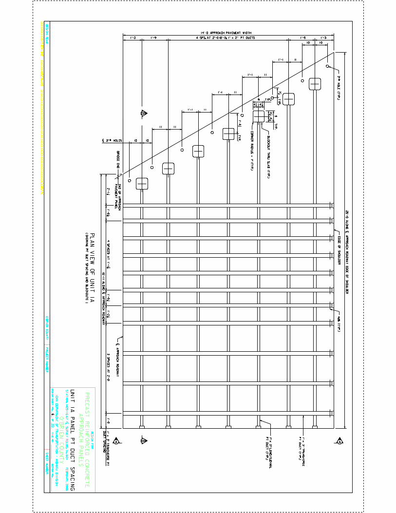
CO
UN
TY
DE
SIG
N S
HE
ET
NO
.O
FD
ES
IGN
NO
.F
ILE
NO
.
IOW
A D
EP
AR
TM
EN
T O
F T
RA
NS
PO
RT
AT
ION
- HIG
HW
AY
DIV
ISIO
N
PR
OJE
CT
NU
MB
ER
SH
EE
T N
UM
BE
R
XX
XX
XX
XX
XX
SY
ST
EM
TIM
EX
XX
XX
XX
US
ER
NA
ME
XX
XX
XX
XX
XX
XX
XX
XX
XX
XX
XX
XX
XX
XX
XX
XX
XX
XX
XX
XX
XX
XX
XX
XX
XX
XX
XD
GN
SP
EC
DE
SIG
N T
EA
M
20
O’B
RIE
N
O’B
RIE
N C
OU
NT
Y
DE
SIG
N F
OR
PR
EC
AS
T R
EIN
FO
RC
ED
CO
NC
RE
TE
ST
AT
IO
N: 1
42
9+
16
.67
(| S
UR
VE
Y R
EL
OC
. IA
. 60
) F
EB
RU
AR
Y, 2
00
6
AP
PR
OA
CH
PA
NE
LS
| AP
PR
OA
CH
RO
AD
WA
Y
ED
GE
OF
SH
OU
LD
ER
2" 5
9/6
4 H
OL
E (T
YP
.)
4 1/2 4 1/2
4 1/2 4 1/2
9
9
CO
RN
ER
RA
DIU
S =
1" (T
YP
.)
1’-3 1’-9 1’-9 1’-3
14’-0 APPROACH PAVEMENT WIDTH
BR
IDG
E E
ND
EN
D O
F A
PP
RO
AC
H
PA
VE
ME
NT
PA
NE
L
10 10
11
111’-1
111’-1
1’-1
10 10
11
16’-1
1 A
LO
NG
| AP
PR
OA
CH
RO
AD
WA
Y
PL
AN
VIE
W O
F U
NIT
1A
11
1’-1
1" x
2" L
ON
GIT
UD
INA
L
PT
DU
CT
(TY
P.)
1" x
3" T
RA
NS
VE
RS
E
PT
DU
CT
(TY
P.)
25’-0
AL
ON
G | A
PP
RO
AC
H R
OA
DW
AY
ED
GE
OF
SH
OU
LD
ER
1’-0 1/8 1’-0 1/8
4 S
PA
CE
S A
T 1
’-1 7
/8
1’-2 1/8 3
SP
AC
ES
AT
2’-0
1’-0
2’-1 1/8
AA
UN
IT 1
A P
AN
EL
PT
DU
CT
SP
AC
ING
( SH
OW
ING
PT
DU
CT
SP
AC
ING
AN
D B
LO
CK
OU
TS
)
1" x
3" T
RA
NS
VE
RS
E P
T
DU
CT
SP
AC
ING
11
| 2" 59/64 HOLES
4 SPS. AT 2’-0=8’-0; 1" x 2" PT DUCTS
TY
P.
TYP.
BL
OC
KO
UT
TH
RU
SL
AB
(TY
P.)
7 1/2 T
YP
.
TY
P.
1’-4 1/2
BB
6
4d6 (
TY
P.)
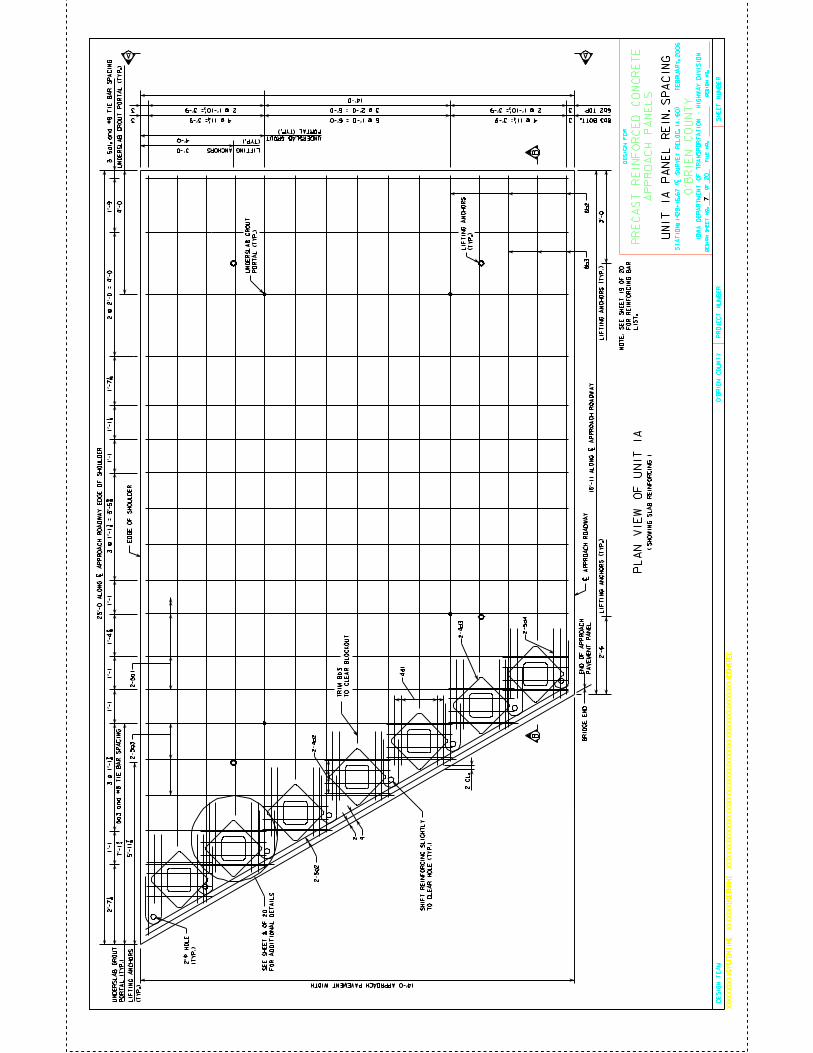
CO
UN
TY
DE
SIG
N S
HE
ET
NO
.O
FD
ES
IGN
NO
.F
ILE
NO
.
IOW
A D
EP
AR
TM
EN
T O
F T
RA
NS
PO
RT
AT
ION
- H
IGH
WA
Y D
IVIS
ION
PR
OJE
CT
NU
MB
ER
SH
EE
T N
UM
BE
R
XX
XX
XX
XX
XX
SY
ST
EM
TIM
EX
XX
XX
XX
US
ER
NA
ME
XX
XX
XX
XX
XX
XX
XX
XX
XX
XX
XX
XX
XX
XX
XX
XX
XX
XX
XX
XX
XX
XX
XX
XX
XX
XX
XD
GN
SP
EC
DE
SIG
N T
EA
M
20
O’B
RIE
N
O’B
RIE
N C
OU
NT
Y
DE
SIG
N F
OR
PR
EC
AS
T R
EIN
FO
RC
ED
CO
NC
RE
TE
ST
AT
IO
N:
1429+
16.6
7 (
| S
UR
VE
Y R
EL
OC
. IA
. 60) F
EB
RU
AR
Y, 2006
AP
PR
OA
CH
PA
NE
LS
| A
PP
RO
AC
H R
OA
DW
AY
ED
GE
OF
SH
OU
LD
ER
14’-0 APPROACH PAVEMENT WIDTH
BR
IDG
E E
ND
EN
D O
F A
PP
RO
AC
H
PA
VE
ME
NT
PA
NE
L1
6’-
11
AL
ON
G | A
PP
RO
AC
H R
OA
DW
AY
PL
AN
VIE
W O
F U
NIT
1A
25’-
0 A
LO
NG
| A
PP
RO
AC
H R
OA
DW
AY
ED
GE
OF
SH
OU
LD
ER
A A
UN
IT 1
A P
AN
EL
RE
IN. S
PA
CIN
G
( S
HO
WIN
G S
LA
B R
EIN
FO
RC
ING
)
31
’-9
2 @
2’-0 =
4’-0
1’-7
1/1
6 1’
-1 1
/8
1’-
13 @
1’-
1 7
/8 =
3’-
5 5
/8
1’-
11
’-1
1’-
11
’-1
2’-7
1/8
3 @
1’-
1 7
/8
1’-4
7/1
6
4 @ 11 1/4 = 3’-9 4 @ 11 1/4 = 3’-96 @ 1’-0 = 6’-03 3
33 3 @ 2’-0 = 6’-02 @ 1’-10 1/2 = 3’-9 2 @ 1’-10 1/2 = 3’-9
14’-0
2-5a2
2 4
2 C
L.
2-4d3
2-5d4
4d
1
2-4d2
SE
E S
HE
ET
8 O
F 2
0
FO
R A
DD
ITIO
NA
L D
ET
AIL
S
6b
28b3
BB
8b3 BOTT.
6b2 TOP
2’-6
LIF
TIN
G A
NC
HO
RS
(T
YP
.)3
’-0
LIF
TIN
G A
NC
HO
RS
(T
YP
.)
4’-0 UNDERSLAB GROUT
PORTAL (TYP.)
3’-0
4’-0
UN
DE
RS
LA
B G
RO
UT
PO
RT
AL
(T
YP
.)U
ND
ER
SL
AB
GR
OU
T
PO
RT
AL
(T
YP
.)7’
-1 3
/4
2"
59/6
4 H
OL
E
(TY
P.)
5’-1
1 7/
8
UN
DE
RS
LA
B G
RO
UT
PO
RT
AL
(T
YP
.)
LIF
TIN
G A
NC
HO
RS
(TY
P.)
TR
IM
8b3
TO
CL
EA
R B
LO
CK
OU
T
LIFTING ANCHORS
(TYP.)
LIF
TIN
G A
NC
HO
RS
(TY
P.)
7
NO
TE
: S
EE
SH
EE
T 1
9 O
F 2
0
FO
R R
EIN
FO
RC
IN
G B
AR
L
IS
T.
SH
IFT
RE
INF
OR
CIN
G S
LIG
HT
LY
TO
CL
EA
R H
OL
E (
TY
P.)
2-5a3
2-5
a1
5a3 a
nd #
8 T
IE
BA
R S
PA
CIN
G
5a1
, an
d #
8 T
IE
BA
R S
PA
CIN
G
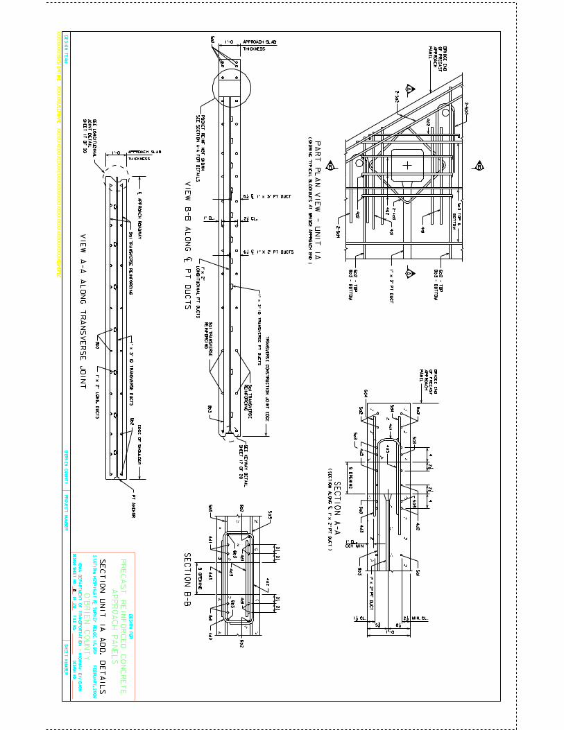
CO
UN
TY
DE
SIG
N S
HE
ET
NO
.O
FD
ES
IGN
NO
.F
ILE
NO
.
IOW
A D
EP
AR
TM
EN
T O
F T
RA
NS
PO
RT
AT
ION
- HIG
HW
AY
DIV
ISIO
N
PR
OJE
CT
NU
MB
ER
SH
EE
T N
UM
BE
R
XX
XX
XX
XX
XX
SY
ST
EM
TIM
EX
XX
XX
XX
US
ER
NA
ME
XX
XX
XX
XX
XX
XX
XX
XX
XX
XX
XX
XX
XX
XX
XX
XX
XX
XX
XX
XX
XX
XX
XX
XX
XX
XX
XD
GN
SP
EC
DE
SIG
N T
EA
M
20
O’B
RIE
N
O’B
RIE
N C
OU
NT
Y
DE
SIG
N F
OR
PR
EC
AS
T R
EIN
FO
RC
ED
CO
NC
RE
TE
ST
AT
IO
N: 1
42
9+
16
.67
(| S
UR
VE
Y R
EL
OC
. IA
. 60
) F
EB
RU
AR
Y, 2
00
6
AP
PR
OA
CH
PA
NE
LS
SE
CT
ION
A-A
( S
EC
TIO
N A
LO
NG
| 1" x
2" P
T D
UC
T )
PA
RT
PL
AN
VIE
W -
UN
IT
1A
SE
CT
ION
UN
IT 1
A A
DD
. DE
TA
ILS
B
A
B
A
BR
IDG
E E
ND
OF
PR
EC
AS
T
AP
PR
OA
CH
PA
NE
L
4d
2
1" x
2" P
T D
UC
T
4d
2
4d1
6b
2 -
TO
P
8b
3 - B
OT
TO
M
6b
2 -
TO
P
8b
3 - B
OT
TO
M
4d1
4d
2
2-5d4
2-5
a2
2-4d3
2-5d4
42 1/2
42 1/2
4d1
4d
3
4d
3
4d
2
4d
2
5a1
8b
3
BR
IDG
E E
ND
OF
PR
EC
AS
T
AP
PR
OA
CH
PA
NE
L5a2
5a2
5a3
5a3
5a3 5a3
5d
4
5d
4
1" x
2" P
T D
UC
T
2 1/2
5 3/4 6 1/4
1’-0
MIN. CL.
9 O
PE
NIN
G
1 1/2 CL.
1" CL.
COV. MIN.
SE
CT
ION
B-B
2 1/2 2 1/2
2 1/2 2 1/2
4d
2
4d
2
4d1
4d1
4d1
4d
3
6b2
6b2
8b
38
b3
4d1
4d
3
9 O
PE
NIN
G
5a3
5a3
( SH
OW
ING
TY
PIC
AL
BL
OC
KO
UT
S A
T B
RID
GE
AP
PR
OA
CH
EN
D )
1’-0
THICKNESS
TR
AN
SV
ER
SE
CO
NS
TR
UC
TIO
N J
OIN
T E
DG
E
APPROACH SLAB
8b
3
2 1/2 CL.
1" x
3" I
D T
RA
NS
VE
RS
E P
T D
UC
TS
5 1/4 | 1" x 3" PT DUCT
6 1/4 | 1" X 2" PT DUCTS
1" CL.
5a1
TR
AN
SV
ER
SE
RE
INF
OR
CIN
G
5a1
TR
AN
SV
ER
SE
RE
INF
OR
CIN
G
5a2
PO
CK
ET
RE
INF
. NO
T S
HO
WN
SE
E S
EC
TIO
N A
-A F
OR
DE
TA
ILS
1" x
2"
LO
NG
ITU
DIN
AL
PT
DU
CT
S
VIE
W A
-A A
LO
NG
TR
AN
SV
ER
SE
JO
INT
1’-0
THICKNESS
| AP
PR
OA
CH
RO
AD
WA
Y
5a1 T
RA
NS
VE
RS
E R
EIN
FO
RC
ING
1" x
3" ID
TR
AN
SV
ER
SE
DU
CT
S
ED
GE
OF
SH
OU
LD
ER
APPROACH SLAB
PT
AN
CH
OR
8b
31" x
2" L
ON
G. D
UC
TS
6b2
5a3
TO
P &
BO
TT
OM
SE
E K
EY
WA
Y D
ET
AIL
SH
EE
T 1
7 O
F 2
0
SE
E L
ON
GIT
UD
INA
L
JO
INT
DE
TA
IL
SH
EE
T 1
7 O
F 2
0
8
VIE
W B
-B
AL
ON
G | P
T D
UC
TS

CO
UN
TY
DE
SIG
N S
HE
ET
NO
.O
FD
ES
IGN
NO
.F
ILE
NO
.
IOW
A D
EP
AR
TM
EN
T O
F T
RA
NS
PO
RT
AT
ION
- H
IGH
WA
Y D
IVIS
ION
PR
OJE
CT
NU
MB
ER
SH
EE
T N
UM
BE
R
XX
XX
XX
XX
XX
SY
ST
EM
TIM
EX
XX
XX
XX
US
ER
NA
ME
XX
XX
XX
XX
XX
XX
XX
XX
XX
XX
XX
XX
XX
XX
XX
XX
XX
XX
XX
XX
XX
XX
XX
XX
XX
XX
XD
GN
SP
EC
DE
SIG
N T
EA
M
20
O’B
RIE
N
O’B
RIE
N C
OU
NT
Y
DE
SIG
N F
OR
PR
EC
AS
T R
EIN
FO
RC
ED
CO
NC
RE
TE
ST
AT
IO
N:
14
29
+1
6.6
7 (
| S
UR
VE
Y R
EL
OC
. IA
. 6
0)
F
EB
RU
AR
Y,
20
06
AP
PR
OA
CH
PA
NE
LS
5a1 T
RA
NS
VE
RS
E R
EIN
FO
RC
ING
5a1 T
RA
NS
VE
RS
E R
EIN
FO
RC
ING
VIE
W B
-B A
LO
NG
ED
GE
OF
| R
OA
DW
AY
VIE
W A
-A A
LO
NG
TR
AN
SV
ER
SE
JO
INT
A
BB
A
A
BB
A
1’-0
THICKNESS
| A
PP
RO
AC
H R
OA
DW
AY
14
’-0
AP
PR
OA
CH
PA
VE
ME
NT
WID
TH
5a1 T
RA
NS
VE
RS
E R
EIN
FO
RC
ING
1" x
3" I
D T
RA
NS
VE
RS
E D
UC
TS
1’-
93
1’-
93
1’-0
THICKNESS
TR
AN
SV
ER
SE
CO
NS
TR
UC
TIO
N J
OIN
T E
DG
ET
RA
NS
VE
RS
E C
ON
ST
RU
CT
ION
JO
INT
ED
GE
8 S
PA
CE
S A
T 2
’-0 =
16’-0;
5a1 T
RA
NS
VE
RS
E R
EIN
FO
RC
IN
G T
OP
AN
D B
OT
TO
M
20
’-0
AP
PR
OA
CH
PA
VE
ME
NT
LE
NG
TH
20
’-0
AP
PR
OA
CH
PA
VE
ME
NT
LE
NG
TH
14’-0 APPROACH PAVEMENT WIDTH
1’-91’-9
1’-
01
’-0
20
’-0
AP
PR
OA
CH
PA
VE
ME
NT
LE
NG
TH
14’-0 APPROACH PAVEMENT WIDTH
| A
PP
RO
AC
H R
OA
DW
AY
| A
PP
RO
AC
H R
OA
DW
AY
SE
CT
ION
UN
IT 2
A
ED
GE
OF
SH
OU
LD
ER
ED
GE
OF
SH
OU
LD
ER
ED
GE
OF
SH
OU
LD
ER
APPROACH SLAB
TRANSVERSE CONSTRUCTION JOINT EDGE
1’-31’-3
PL
AN
VIE
W S
HO
WIN
G T
OP
& B
OT
TO
M M
AT
PL
AN
VIE
W S
HO
WIN
G P
OS
T-T
EN
SIO
NIN
G D
UC
TS
TR
AN
SV
ER
SE
LY
AN
D L
ON
GIT
UD
INA
LL
Y
2-5
a1 T
RA
NS
VE
RS
E
RE
INF
OR
CIN
G
(TO
P &
BO
TT
OM
)
(TO
P &
BO
TT
OM
)
TRANSVERSE CONSTRUCTION JOINT EDGE
(FEMALE JOINT)
TRANSVERSE CONSTRUCTION JOINT EDGE
(MALE JOINT)
3
APPROACH SLAB
PT
AN
CH
OR
3
PT
AN
CH
OR
1’-
91’-
9
TRANSV. CONSTRUCTION JOINT EDGE
4 @ 2’-0 = 8’-0; 1" x 2" LONG. DUCTS
1" x
3" I
D
TR
AN
SV
ER
SE
PT
DU
CT
S
1" x
2"
LO
NG
ITU
DIN
AL
PT
DU
CT
S
9 S
PA
CE
S A
T 2
’-0
= 1
8’-0
; 1
" x
3" T
RA
NS
VE
RS
E P
T D
UC
TS
4d6
(TY
P.)
LIF
TIN
G A
NC
HO
RS
(TY
P.)
4’-0
2’-9LIFTING
ANCHORS (TYP.)
6b1 R
EIN
FO
RC
ING
5’-0
UN
DE
RS
LA
B G
RO
UT
PO
RT
AL
(T
YP
.)
4’-0UNDERSLAB GROUT PORTAL (TYP.)
UN
DE
RS
LA
B G
RO
UT
PO
RT
AL
(T
YP
.)
LIF
TIN
G A
NC
HO
RS
(TY
P.)
6b1
2 1/2 CL. 1"
CL.
1" x
3" I
D T
RA
NS
VE
RS
E P
T D
UC
TS
1" x
2"
LO
NG
ITU
DIN
AL
PT
DU
CT
S
OF
RE
INF
OR
CIN
G
AL
L R
EIN
FO
RC
EM
EN
T T
O B
E E
PO
XY
CO
AT
ED
6b1
5 S
PA
CE
S A
T 2
’-0 =
10’-0;
6b1 R
EIN
FO
RC
IN
G T
OP
AN
D B
OT
TO
M
1" x
2" L
ON
G. D
UC
TS
5 1/4 | 1" x 3" PT DUCT
6 1/4 | 1" x 2" PT DUCTS
SE
E K
EY
WA
Y
DE
TA
IL
SH
EE
T 1
7 O
F 2
0
SE
E K
EY
WA
Y D
ET
AIL
SH
EE
T 1
7 O
F 2
0
SE
E L
ON
GIT
UD
INA
L
JO
INT
DE
TA
IL
SH
EE
T 1
7 O
F 2
0
9
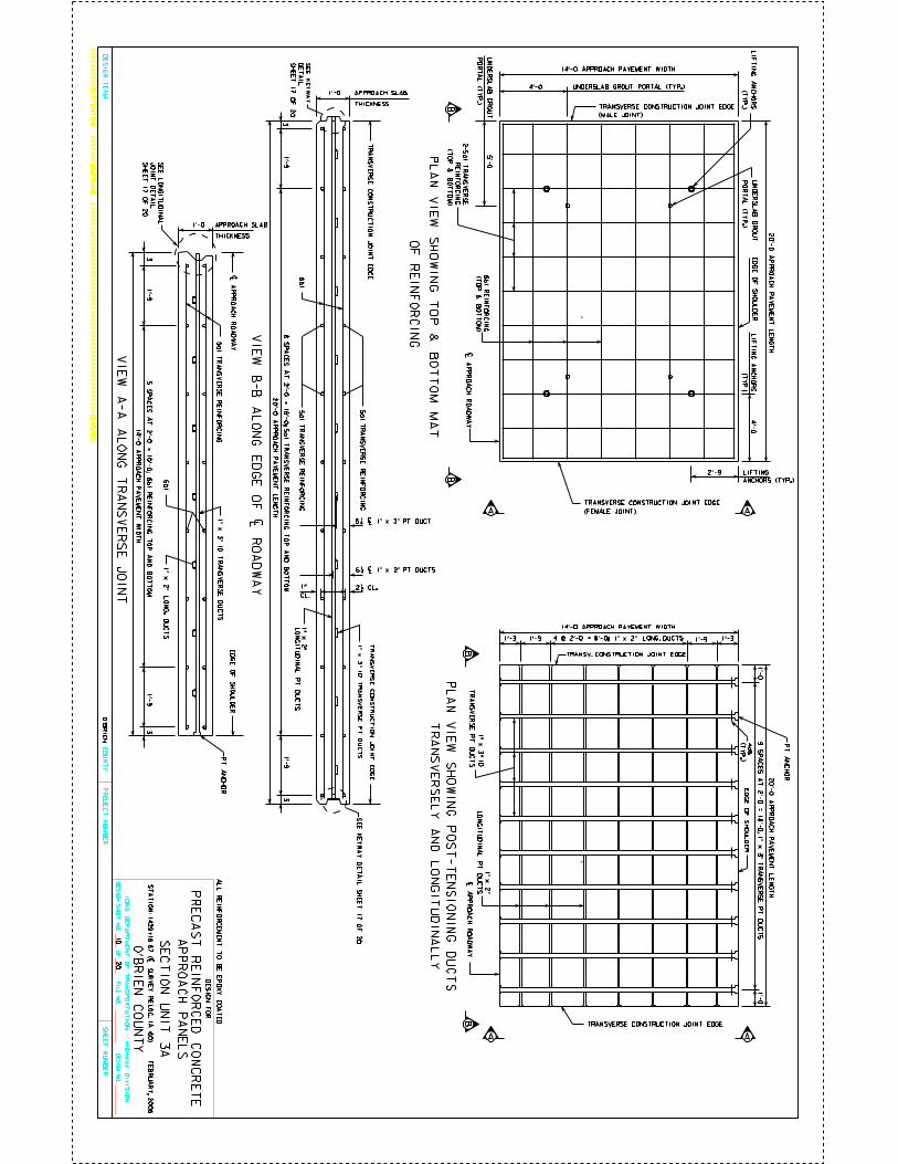
CO
UN
TY
DE
SIG
N S
HE
ET
NO
.O
FD
ES
IGN
NO
.F
ILE
NO
.
IOW
A D
EP
AR
TM
EN
T O
F T
RA
NS
PO
RT
AT
ION
- HIG
HW
AY
DIV
ISIO
N
PR
OJE
CT
NU
MB
ER
SH
EE
T N
UM
BE
R
XX
XX
XX
XX
XX
SY
ST
EM
TIM
EX
XX
XX
XX
US
ER
NA
ME
XX
XX
XX
XX
XX
XX
XX
XX
XX
XX
XX
XX
XX
XX
XX
XX
XX
XX
XX
XX
XX
XX
XX
XX
XX
XX
XD
GN
SP
EC
DE
SIG
N T
EA
M
20
O’B
RIE
N
O’B
RIE
N C
OU
NT
Y
DE
SIG
N F
OR
PR
EC
AS
T R
EIN
FO
RC
ED
CO
NC
RE
TE
ST
AT
IO
N: 1
42
9+
16
.67
(| S
UR
VE
Y R
EL
OC
. IA
. 60
) F
EB
RU
AR
Y, 2
00
6
AP
PR
OA
CH
PA
NE
LS
5a1
TR
AN
SV
ER
SE
RE
INF
OR
CIN
G
5a1
TR
AN
SV
ER
SE
RE
INF
OR
CIN
G
VIE
W B
-B A
LO
NG
ED
GE
OF
| RO
AD
WA
Y
VIE
W A
-A A
LO
NG
TR
AN
SV
ER
SE
JO
INT
A
BB
A
A
BB
A
1’-0
THICKNESS
| AP
PR
OA
CH
RO
AD
WA
Y
14’-0
AP
PR
OA
CH
PA
VE
ME
NT
WID
TH
5a1
TR
AN
SV
ER
SE
RE
INF
OR
CIN
G1
" x
3" ID
TR
AN
SV
ER
SE
DU
CT
S
1’-9
31
’-93
1’-0
THICKNESS
TR
AN
SV
ER
SE
CO
NS
TR
UC
TIO
N J
OIN
T E
DG
ET
RA
NS
VE
RS
E C
ON
ST
RU
CT
ION
JO
INT
ED
GE
8 S
PA
CE
S A
T 2
’-0 =
16’-0; 5
a1 T
RA
NS
VE
RS
E R
EIN
FO
RC
IN
G T
OP
AN
D B
OT
TO
M
20’-0
AP
PR
OA
CH
PA
VE
ME
NT
LE
NG
TH
20’-0
AP
PR
OA
CH
PA
VE
ME
NT
LE
NG
TH
14’-0 APPROACH PAVEMENT WIDTH
1’-9 1’-9
1’-0
1’-0
20’-0
AP
PR
OA
CH
PA
VE
ME
NT
LE
NG
TH
14’-0 APPROACH PAVEMENT WIDTH
| AP
PR
OA
CH
RO
AD
WA
Y| A
PP
RO
AC
H R
OA
DW
AY
SE
CT
ION
UN
IT 3
A
ED
GE
OF
SH
OU
LD
ER
ED
GE
OF
SH
OU
LD
ER
ED
GE
OF
SH
OU
LD
ER
APPROACH SLAB
TRANSVERSE CONSTRUCTION JOINT EDGE
1’-3 1’-3
PL
AN
VIE
W S
HO
WIN
G T
OP
& B
OT
TO
M M
AT
PL
AN
VIE
W S
HO
WIN
G P
OS
T-T
EN
SIO
NIN
G D
UC
TS
TR
AN
SV
ER
SE
LY
AN
D L
ON
GIT
UD
INA
LL
Y
2-5
a1
TR
AN
SV
ER
SE
RE
INF
OR
CIN
G
(TO
P &
BO
TT
OM
)
(TO
P &
BO
TT
OM
)
TRANSVERSE CONSTRUCTION JOINT EDGE
(FEMALE JOINT)
TRANSVERSE CONSTRUCTION JOINT EDGE
(MALE JOINT)
3
APPROACH SLAB
PT
AN
CH
OR
3
PT
AN
CH
OR
1’-9
1’-9
TRANSV. CONSTRUCTION JOINT EDGE
4 @ 2’-0 = 8’-0; 1" x 2" LONG. DUCTS
1" x
3" I
D
TR
AN
SV
ER
SE
PT
DU
CT
S
1" x
2"
LO
NG
ITU
DIN
AL
PT
DU
CT
S
9 S
PA
CE
S A
T 2
’-0
= 1
8’-0
; 1" x
3" T
RA
NS
VE
RS
E P
T D
UC
TS
4d6
(TY
P.)
LIF
TIN
G A
NC
HO
RS
(TY
P.)
4’-0
2’-9 LIFTING
ANCHORS (TYP.)
6b
1 R
EIN
FO
RC
ING
5’-0
UN
DE
RS
LA
B G
RO
UT
PO
RT
AL
(TY
P.)
4’-0 UNDERSLAB GROUT PORTAL (TYP.)
UN
DE
RS
LA
B G
RO
UT
PO
RT
AL
(TY
P.)
LIF
TIN
G A
NC
HO
RS
(TY
P.)
6b
1
2 1/2 CL.1"
CL.
1" x
3" I
D T
RA
NS
VE
RS
E P
T D
UC
TS
1" x
2"
LO
NG
ITU
DIN
AL
PT
DU
CT
S
OF
RE
INF
OR
CIN
G
AL
L R
EIN
FO
RC
EM
EN
T T
O B
E E
PO
XY
CO
AT
ED
6b
1
5 S
PA
CE
S A
T 2
’-0 =
10’-0; 6
b1 R
EIN
FO
RC
IN
G T
OP
AN
D B
OT
TO
M
1" x
2" L
ON
G. D
UC
TS
5 1/4 | 1" x 3" PT DUCT
6 1/4 | 1" x 2" PT DUCTS
SE
E L
ON
GIT
UD
INA
L
JO
INT
DE
TA
IL
SH
EE
T 1
7 O
F 2
0
SE
E K
EY
WA
Y
DE
TA
IL
SH
EE
T 1
7 O
F 2
0
SE
E K
EY
WA
Y D
ET
AIL
SH
EE
T 1
7 O
F 2
010
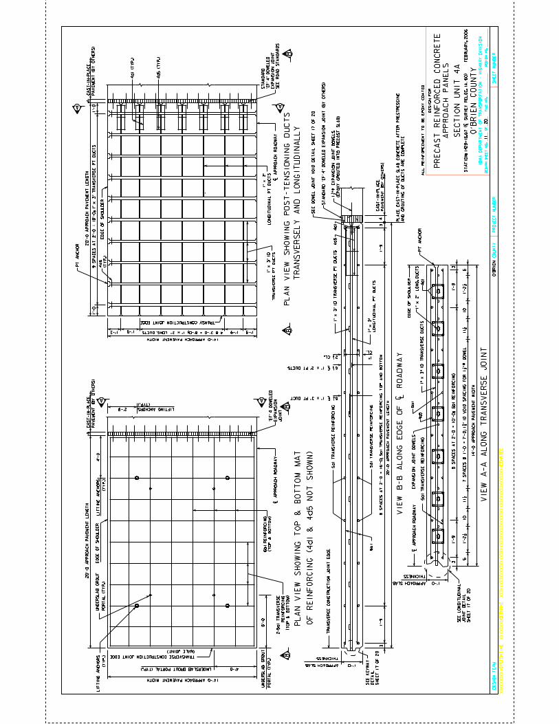
CO
UN
TY
DE
SIG
N S
HE
ET
NO
.O
FD
ES
IGN
NO
.F
ILE
NO
.
IOW
A D
EP
AR
TM
EN
T O
F T
RA
NS
PO
RT
AT
ION
- H
IGH
WA
Y D
IVIS
ION
PR
OJE
CT
NU
MB
ER
SH
EE
T N
UM
BE
R
XX
XX
XX
XX
XX
SY
ST
EM
TIM
EX
XX
XX
XX
US
ER
NA
ME
XX
XX
XX
XX
XX
XX
XX
XX
XX
XX
XX
XX
XX
XX
XX
XX
XX
XX
XX
XX
XX
XX
XX
XX
XX
XX
XD
GN
SP
EC
DE
SIG
N T
EA
M
20
O’B
RIE
N
O’B
RIE
N C
OU
NT
Y
DE
SIG
N F
OR
PR
EC
AS
T R
EIN
FO
RC
ED
CO
NC
RE
TE
ST
AT
IO
N:
1429+
16.6
7 (
| S
UR
VE
Y R
EL
OC
. IA
. 60) F
EB
RU
AR
Y, 2006
AP
PR
OA
CH
PA
NE
LS
5a1
TR
AN
SV
ER
SE
RE
INF
OR
CIN
G
5a1
TR
AN
SV
ER
SE
RE
INF
OR
CIN
G
VIE
W B
-B A
LO
NG
ED
GE
OF
| R
OA
DW
AY
VIE
W A
-A A
LO
NG
TR
AN
SV
ER
SE
JO
INT
A
BB
A
A
BB
A
1’-0
THICKNESS
| A
PP
RO
AC
H R
OA
DW
AY
14’-
0 A
PP
RO
AC
H P
AV
EM
EN
T W
IDT
H
5a1
TR
AN
SV
ER
SE
RE
INF
OR
CIN
G1" x
3" I
D T
RA
NS
VE
RS
E D
UC
TS
1’-
93
1’-
93
1’-0
THICKNESS
TR
AN
SV
ER
SE
CO
NS
TR
UC
TIO
N J
OIN
T E
DG
E
8 S
PA
CE
S A
T 2
’-0
= 1
6’-0
; 5
a1
TR
AN
SV
ER
SE
RE
IN
FO
RC
IN
G T
OP
AN
D B
OT
TO
M
20’-
0 A
PP
RO
AC
H P
AV
EM
EN
T L
EN
GT
H
20’-
0 A
PP
RO
AC
H P
AV
EM
EN
T L
EN
GT
H
14’-0 APPROACH PAVEMENT WIDTH
1’-91’-9
1’-
01
’-0
20’-
0 A
PP
RO
AC
H P
AV
EM
EN
T L
EN
GT
H
14’-0 APPROACH PAVEMENT WIDTH
| A
PP
RO
AC
H R
OA
DW
AY
| A
PP
RO
AC
H R
OA
DW
AY S
EC
TIO
N U
NIT
4A
ED
GE
OF
SH
OU
LD
ER
ED
GE
OF
SH
OU
LD
ER
APPROACH SLAB
1’-31’-3
PL
AN
VIE
W S
HO
WIN
G T
OP
& B
OT
TO
M M
AT
PL
AN
VIE
W S
HO
WIN
G P
OS
T-T
EN
SIO
NIN
G D
UC
TS
TR
AN
SV
ER
SE
LY
AN
D L
ON
GIT
UD
INA
LL
Y
2-5
a1 T
RA
NS
VE
RS
E
RE
INF
OR
CIN
G
(TO
P &
BO
TT
OM
)
(TO
P &
BO
TT
OM
)
TRANSVERSE CONSTRUCTION JOINT EDGE
(MALE JOINT)
3
APPROACH SLAB
PT
AN
CH
OR
3
PT
AN
CH
OR
1’-
91
’-9
TRANSV. CONSTRUCTION JOINT EDGE
1" x
3" I
D
TR
AN
SV
ER
SE
PT
DU
CT
S
1" x
2"
LO
NG
ITU
DIN
AL
PT
DU
CT
S
9 S
PA
CE
S A
T 2
’-0
= 1
8’-0
; 1
" x
3" T
RA
NS
VE
RS
E P
T D
UC
TS
4d
6
(TY
P.)
LIF
TIN
G A
NC
HO
RS
(TY
P.)
4’-0
2’-9
6b
1 R
EIN
FO
RC
ING
5’-0
UN
DE
RS
LA
B G
RO
UT
PO
RT
AL
(T
YP
.)
4’-0UNDERSLAB GROUT PORTAL (TYP.)
UN
DE
RS
LA
B G
RO
UT
PO
RT
AL
(T
YP
.)
LIF
TIN
G A
NC
HO
RS
(TY
P.)
6b1
2 1/2 CL. 1"
CL.
1" x
3" I
D T
RA
NS
VE
RS
E P
T D
UC
TS
1" x
2"
LO
NG
ITU
DIN
AL
PT
DU
CT
S
AL
L R
EIN
FO
RC
EM
EN
T T
O B
E E
PO
XY
CO
AT
ED
1" x
2" L
ON
G. D
UC
TS
4 @ 2’-0 = 8’-0; 1" x 2" LONG. DUCTS
44
’EF
’ 4 D
OW
EL
ED
EX
PA
NS
ION
JO
INT
6
ED
GE
OF
SH
OU
LD
ER
EX
PA
NS
ION
JO
INT
DO
WE
LS
(TYP.)
LIFTING ANCHORSO
F R
EIN
FO
RC
ING
(4
d1
& 4
d5
NO
T S
HO
WN
)
4
4d5
4d
1
4d5
4d
1
5 1/4 | 1" x 3" PT DUCT
6 1/4 | 1" x 2" PT DUCTS
SE
E K
EY
WA
Y
DE
TA
IL
SH
EE
T 1
7 O
F 2
0
SE
E L
ON
GIT
UD
INA
L
JO
INT
DE
TA
IL
SH
EE
T 1
7 O
F 2
0
11
CA
ST
-IN
-PL
AC
E
PA
VE
ME
NT
(B
Y O
TH
ER
S)
CA
ST
-IN
-PL
AC
E
PA
VE
ME
NT
(B
Y O
TH
ER
S)
ST
AN
DA
RD
’E
F’
4" D
OW
EL
ED
EX
PA
NS
ION
JO
INT
(B
Y O
TH
ER
S)
SE
E D
OW
EL
JO
IN
T V
OID
DE
TA
IL
SH
EE
T 1
7 O
F 2
0
5 S
PA
CE
S A
T 2
’-0
= 1
0’-0
; 6
b1
RE
IN
FO
RC
IN
G
6b1
10
11 1/
2 11
1/2
10
67
SP
AC
ES
@ 1
’-0
= 7
’-0
; 1
5/8
" I
D V
OID
SP
AC
ING
FO
R 1
1/2
" 5
9/6
4
DO
WE
L
4d1 (
TY
P.)
4d5 (
TY
P.)
1’-2
1/2
1’
-2 1
/2
ST
AN
DA
RD
’EF
’ 4" D
OW
EL
ED
EX
PA
NS
ION
JO
INT
SE
E R
OA
D S
TA
ND
AR
DS
1 1
/2 "
59
/64
E
XP
AN
SIO
N J
OIN
T D
OW
EL
S
(EP
OX
Y G
RO
UT
ED
IN
TO
PR
EC
AS
T S
LA
B)
CA
ST
-IN
-PL
AC
E
PA
VE
ME
NT
(B
Y O
TH
ER
S)
PL
AC
E C
AS
T-I
N-P
LA
CE
SL
AB
CO
NC
RE
TE
AF
TE
R P
RE
ST
RE
SS
ING
AN
D G
RO
UT
ING
OF
DU
CT
S A
RE
CO
MP
LE
TE
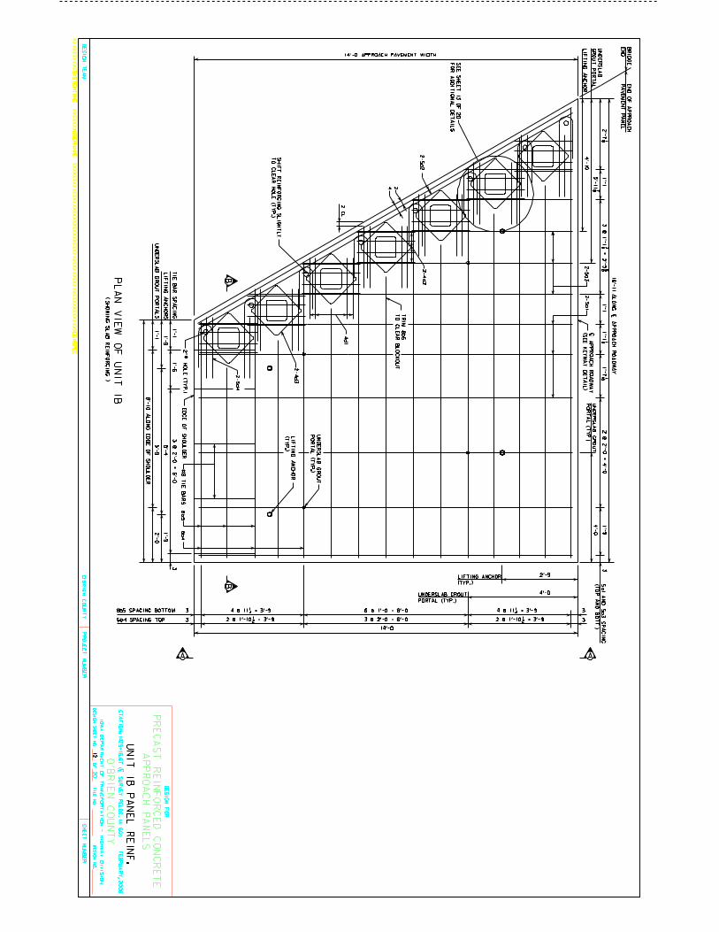
CO
UN
TY
DE
SIG
N S
HE
ET
NO
.O
FD
ES
IGN
NO
.F
ILE
NO
.
IOW
A D
EP
AR
TM
EN
T O
F T
RA
NS
PO
RT
AT
ION
- HIG
HW
AY
DIV
ISIO
N
PR
OJE
CT
NU
MB
ER
SH
EE
T N
UM
BE
R
XX
XX
XX
XX
XX
SY
ST
EM
TIM
EX
XX
XX
XX
US
ER
NA
ME
XX
XX
XX
XX
XX
XX
XX
XX
XX
XX
XX
XX
XX
XX
XX
XX
XX
XX
XX
XX
XX
XX
XX
XX
XX
XX
XD
GN
SP
EC
DE
SIG
N T
EA
M
20
O’B
RIE
N
O’B
RIE
N C
OU
NT
Y
DE
SIG
N F
OR
PR
EC
AS
T R
EIN
FO
RC
ED
CO
NC
RE
TE
ST
AT
IO
N: 1
42
9+
16
.67
(| S
UR
VE
Y R
EL
OC
. IA
. 60
) F
EB
RU
AR
Y, 2
00
6
AP
PR
OA
CH
PA
NE
LS
ED
GE
OF
SH
OU
LD
ER
2" 5
9/6
4 H
OL
E (T
YP
.)
14’-0 APPROACH PAVEMENT WIDTH
EN
D O
F A
PP
RO
AC
H
PA
VE
ME
NT
PA
NE
L
16’-1
1 A
LO
NG
| AP
PR
OA
CH
RO
AD
WA
Y
PL
AN
VIE
W O
F U
NIT
1B 8
’-10 A
LO
NG
ED
GE
OF
SH
OU
LD
ER
2’-7 1/8 1’-1 1/8
1’-7 1/16 1
’-13 @
1’-1
7/8
= 3
’-5 5
/8
1’-1
2 @
2’-0
= 4
’-0
1’-9
3
4 @ 11 1/4 = 3’-9 4 @ 11 1/4 = 3’-96 @ 1’-0 = 6’-0 33
14’-0
3 @
2’-0 =
6’-0
1’-6
1’-1
3T
IE B
AR
SP
AC
ING
4d
12 C
L.
8b
5
24
#8 T
IE
BA
RS
3 @ 2’-0 = 6’-03 3
6b4
UN
IT 1
B P
AN
EL
RE
INF
.
( SH
OW
ING
SL
AB
RE
INF
OR
CIN
G )
2-5
a2
2-4
d2
2-4
d3
2-5
d4
2 @ 1’-10 1/2 = 3’-9 2 @ 1’-10 1/2 = 3’-9 6b4 SPACING TOP
8b5 SPACING BOTTOM
5a1 A
ND
5a3 S
PA
CIN
G
(TO
P A
ND
BO
TT
.)
BB
A A
2’-9
4’-0
LIFTING ANCHOR
(TYP.)
UNDERSLAB GROUT
PORTAL (TYP.)
1’-9
1’-1
LIF
TIN
G A
NC
HO
RS
UN
DE
RS
LA
B G
RO
UT
PO
RT
AL
S
1’-9
2’-0
5’-4
5’-9
4’-0
| AP
PR
OA
CH
RO
AD
WA
Y
(SE
E K
EY
WA
Y D
ET
AIL
)
UN
DE
RS
LA
B G
RO
UT
PO
RT
AL
(TY
P.)
BR
IDG
E
EN
D
5’-11 7/8
4’-1
0
UN
DE
RS
LA
B G
RO
UT
PO
RT
AL
(TY
P.)
LIF
TIN
G A
NC
HO
R
(TY
P.)
TR
IM
8b5
TO
CL
EA
R B
LO
CK
OU
T
UN
DE
RS
LA
B
GR
OU
T P
OR
TA
L
LIF
TIN
G A
NC
HO
R
SE
E S
HE
ET
13 O
F 2
0
FO
R A
DD
ITIO
NA
L D
ET
AIL
S
12
SH
IFT
RE
INF
OR
CIN
G S
LIG
HT
LY
TO
CL
EA
R H
OL
E (T
YP
.)
2-5
a3
2-5a1
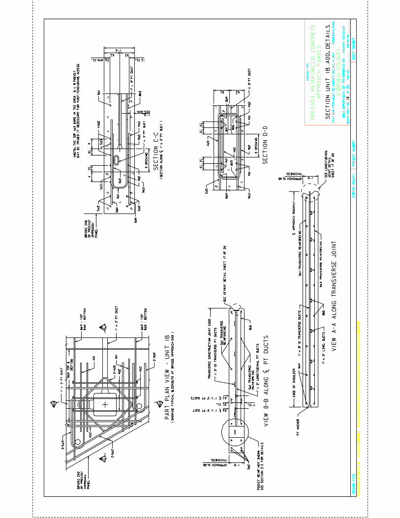
CO
UN
TY
DE
SIG
N S
HE
ET
NO
.O
FD
ES
IGN
NO
.F
ILE
NO
.
IOW
A D
EP
AR
TM
EN
T O
F T
RA
NS
PO
RT
AT
ION
- H
IGH
WA
Y D
IVIS
ION
PR
OJE
CT
NU
MB
ER
SH
EE
T N
UM
BE
R
XX
XX
XX
XX
XX
SY
ST
EM
TIM
EX
XX
XX
XX
US
ER
NA
ME
XX
XX
XX
XX
XX
XX
XX
XX
XX
XX
XX
XX
XX
XX
XX
XX
XX
XX
XX
XX
XX
XX
XX
XX
XX
XX
XD
GN
SP
EC
DE
SIG
N T
EA
M
20
O’B
RIE
N
O’B
RIE
N C
OU
NT
Y
DE
SIG
N F
OR
PR
EC
AS
T R
EIN
FO
RC
ED
CO
NC
RE
TE
ST
AT
IO
N:
1429+
16.6
7 (
| S
UR
VE
Y R
EL
OC
. IA
. 60) F
EB
RU
AR
Y, 2006
AP
PR
OA
CH
PA
NE
LS
D
C
D
C
SE
CT
ION
C-C
SE
CT
ION
D-D
42 1
/2 4
2 1/2
4d
14d3
4d3
*4d2
4d2
5a1
2 1/2
2 1/2
2 1/2
2 1/2
4d2
4d2
4d
1
4d
14
d1
8b5
4d3
6b
46
b4
8b5
8b5
4d
1
4d3
( S
EC
TIO
N A
LO
NG
| 1
" x
2" P
T D
UC
T )
BR
IDG
E E
ND
OF
PR
EC
AS
T
AP
PR
OA
CH
PA
NE
L5
a2
5a2
5a3
5a3
5a35a3
5d4
5d4
BR
IDG
E E
ND
OF
PR
EC
AS
T
AP
PR
OA
CH
PA
NE
L
4d2
1" x
2" P
T D
UC
T
4d2
4d
1
6b4 -
TO
P
8b5 -
BO
TT
OM
6b4 -
TO
P
8b5 -
BO
TT
OM
4d
1
4d2
1" x
2" P
T D
UC
T
2 1/2
5 3/4 6 1/4
1’-0
MIN. CL.
9 O
PE
NIN
G
9 O
PE
NIN
G
PA
RT
PL
AN
VIE
W -
UN
IT
1B
1" x
3" P
T D
UC
T
1" x
3" P
T D
UC
T
1" x
3" P
T D
UC
T
2-5d4
2-5a2
2-4d3
2-5d4
1 1/2 CL.
1" CL.
COV. MIN.
5 1/4 6 3/4
SE
CT
ION
UN
IT 1
B A
DD
. D
ET
AIL
S
( S
HO
WIN
G T
YP
ICA
L B
LO
CK
OU
TS
AT
BR
IDG
E A
PP
RO
AC
H E
ND
)
5a3
5a3
VIE
W A
-A A
LO
NG
TR
AN
SV
ER
SE
JO
INT
1’-0
THICKNESS
| A
PP
RO
AC
H R
OA
DW
AY
5a1
TR
AN
SV
ER
SE
RE
INF
OR
CIN
G1" x
3" I
D T
RA
NS
VE
RS
E D
UC
TS
ED
GE
OF
SH
OU
LD
ER
APPROACH SLAB
PT
AN
CH
OR
8b5
1" x
2" L
ON
G. D
UC
TS
5a3
TR
AN
SV
ER
SE
RE
INF
OR
CIN
G
6b
4
1’-0
THICKNESS
TR
AN
SV
ER
SE
CO
NS
TR
UC
TIO
N J
OIN
T E
DG
E
APPROACH SLAB
8b5
2 1/2 CL.
1" x
3" I
D T
RA
NS
VE
RS
E P
T D
UC
TS
5 1/4 | 1" x 3" PT DUCT
6 1/4 | 1" X 2" PT DUCTS
VIE
W B
-B
AL
ON
G | P
T D
UC
TS
1" CL.
1" x
2" L
ON
GIT
UD
INA
L P
T D
UC
TS
5a1 T
RA
NS
VE
RS
E
RE
INF
OR
CIN
G
5a1 T
RA
NS
VE
RS
E
RE
INF
OR
CIN
G
5a2
PO
CK
ET
RE
INF
. N
OT
SH
OW
N
SE
E S
EC
TIO
N C
-C F
OR
DE
TA
ILS
5a3
TO
P &
BO
TT
OM
SE
E K
EY
WA
Y D
ET
AIL
SH
EE
T 1
7 O
F 2
0
SE
E L
ON
GIT
UD
INA
L
JO
INT
DE
TA
IL
SH
EE
T 1
7 O
F 2
0
13
*N
OT
E:
TH
E T
OP
4d2 B
AR
S I
N T
HE
OP
EN
9 x
9 P
OC
KE
T
MA
Y B
E T
RIM
ED
IF
NE
CE
SS
AR
Y F
OR
PO
ST
-TE
NS
ION
ING
AC
CE
SS
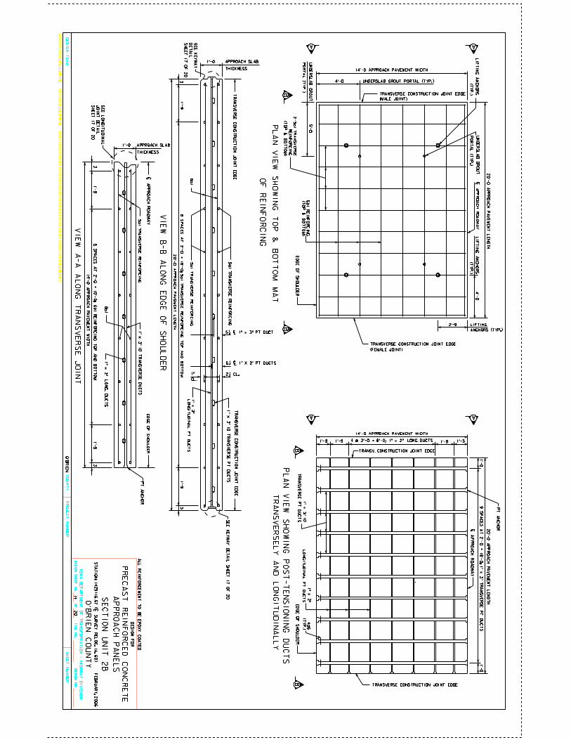
CO
UN
TY
DE
SIG
N S
HE
ET
NO
.O
FD
ES
IGN
NO
.F
ILE
NO
.
IOW
A D
EP
AR
TM
EN
T O
F T
RA
NS
PO
RT
AT
ION
- HIG
HW
AY
DIV
ISIO
N
PR
OJE
CT
NU
MB
ER
SH
EE
T N
UM
BE
R
XX
XX
XX
XX
XX
SY
ST
EM
TIM
EX
XX
XX
XX
US
ER
NA
ME
XX
XX
XX
XX
XX
XX
XX
XX
XX
XX
XX
XX
XX
XX
XX
XX
XX
XX
XX
XX
XX
XX
XX
XX
XX
XX
XD
GN
SP
EC
DE
SIG
N T
EA
M
20
O’B
RIE
N
O’B
RIE
N C
OU
NT
Y
DE
SIG
N F
OR
PR
EC
AS
T R
EIN
FO
RC
ED
CO
NC
RE
TE
ST
AT
IO
N: 1
42
9+
16
.67
(| S
UR
VE
Y R
EL
OC
. IA
. 60
) F
EB
RU
AR
Y, 2
00
6
AP
PR
OA
CH
PA
NE
LS
5a1 T
RA
NS
VE
RS
E R
EIN
FO
RC
ING
5a1 T
RA
NS
VE
RS
E R
EIN
FO
RC
ING
VIE
W B
-B A
LO
NG
ED
GE
OF
SH
OU
LD
ER
VIE
W A
-A A
LO
NG
TR
AN
SV
ER
SE
JO
INT
A
BB
A
A
BB
A
1’-0
THICKNESS
| AP
PR
OA
CH
RO
AD
WA
Y
14’-0
AP
PR
OA
CH
PA
VE
ME
NT
WID
TH
5a1 T
RA
NS
VE
RS
E R
EIN
FO
RC
ING
1" x
3" ID
TR
AN
SV
ER
SE
DU
CT
S
1’-9
31’-9
3
1’-0
THICKNESS
TR
AN
SV
ER
SE
CO
NS
TR
UC
TIO
N J
OIN
T E
DG
ET
RA
NS
VE
RS
E C
ON
ST
RU
CT
ION
JO
INT
ED
GE
8 S
PA
CE
S A
T 2
’-0 =
16’-0; 5
a1 T
RA
NS
VE
RS
E R
EIN
FO
RC
IN
G T
OP
AN
D B
OT
TO
M
20’-0
AP
PR
OA
CH
PA
VE
ME
NT
LE
NG
TH
20’-0
AP
PR
OA
CH
PA
VE
ME
NT
LE
NG
TH
14’-0 APPROACH PAVEMENT WIDTH
1’-9 1’-9
1’-0
1’-0
20’-0
AP
PR
OA
CH
PA
VE
ME
NT
LE
NG
TH
14’-0 APPROACH PAVEMENT WIDTH
| AP
PR
OA
CH
RO
AD
WA
Y
| AP
PR
OA
CH
RO
AD
WA
Y
SE
CT
ION
UN
IT 2
B
ED
GE
OF
SH
OU
LD
ER
ED
GE
OF
SH
OU
LD
ER
ED
GE
OF
SH
OU
LD
ER
APPROACH SLAB
TRANSVERSE CONSTRUCTION JOINT EDGE
1’-3 1’-3
PL
AN
VIE
W S
HO
WIN
G T
OP
& B
OT
TO
M M
AT
PL
AN
VIE
W S
HO
WIN
G P
OS
T-T
EN
SIO
NIN
G D
UC
TS
TR
AN
SV
ER
SE
LY
AN
D L
ON
GIT
UD
INA
LL
Y
2-5
a1
TR
AN
SV
ER
SE
RE
INF
OR
CIN
G
(TO
P &
BO
TT
OM
)
(TO
P &
BO
TT
OM
)
TRANSVERSE CONSTRUCTION JOINT EDGE
(FEMALE JOINT)
TRANSVERSE CONSTRUCTION JOINT EDGE
(MALE JOINT)
3
APPROACH SLAB
PT
AN
CH
OR
3
PT
AN
CH
OR
1’-9
1’-9
TRANSV. CONSTRUCTION JOINT EDGE
4 @ 2’-0 = 8’-0; 1" x 2" LONG. DUCTS
1" x
3" I
D
TR
AN
SV
ER
SE
PT
DU
CT
S
1" x
2"
LO
NG
ITU
DIN
AL
PT
DU
CT
S
9 S
PA
CE
S A
T 2
’-0 =
18’-0; 1
" x
3" T
RA
NS
VE
RS
E P
T D
UC
TS
4d6
(TY
P.)
LIF
TIN
G A
NC
HO
RS
(TY
P.)
4’-0
2’-9 LIFTING
ANCHORS (TYP.)
6b1 R
EIN
FO
RC
ING
5’-0
UN
DE
RS
LA
B G
RO
UT
PO
RT
AL
(TY
P.)
4’-0 UNDERSLAB GROUT PORTAL (TYP.)
UN
DE
RS
LA
B G
RO
UT
PO
RT
AL
(TY
P.)
LIF
TIN
G A
NC
HO
RS
(TY
P.)
6b
1
2 1/2 CL.1"
CL.
1" x
3" I
D T
RA
NS
VE
RS
E P
T D
UC
TS
1" x
2"
LO
NG
ITU
DIN
AL
PT
DU
CT
S
OF
RE
INF
OR
CIN
G
AL
L R
EIN
FO
RC
EM
EN
T T
O B
E E
PO
XY
CO
AT
ED
6b
1
5 S
PA
CE
S A
T 2
’-0
= 1
0’-0
; 6b
1 R
EIN
FO
RC
IN
G T
OP
AN
D B
OT
TO
M
1" x
2" L
ON
G. D
UC
TS
5 1/4 | 1" x 3" PT DUCT
6 1/4 | 1" X 2" PT DUCTS
SE
E K
EY
WA
Y
DE
TA
IL
SH
EE
T 1
7 O
F 2
0
SE
E L
ON
GIT
UD
INA
L
JO
INT
DE
TA
IL
SH
EE
T 1
7 O
F 2
0
SE
E K
EY
WA
Y D
ET
AIL
SH
EE
T 1
7 O
F 2
014
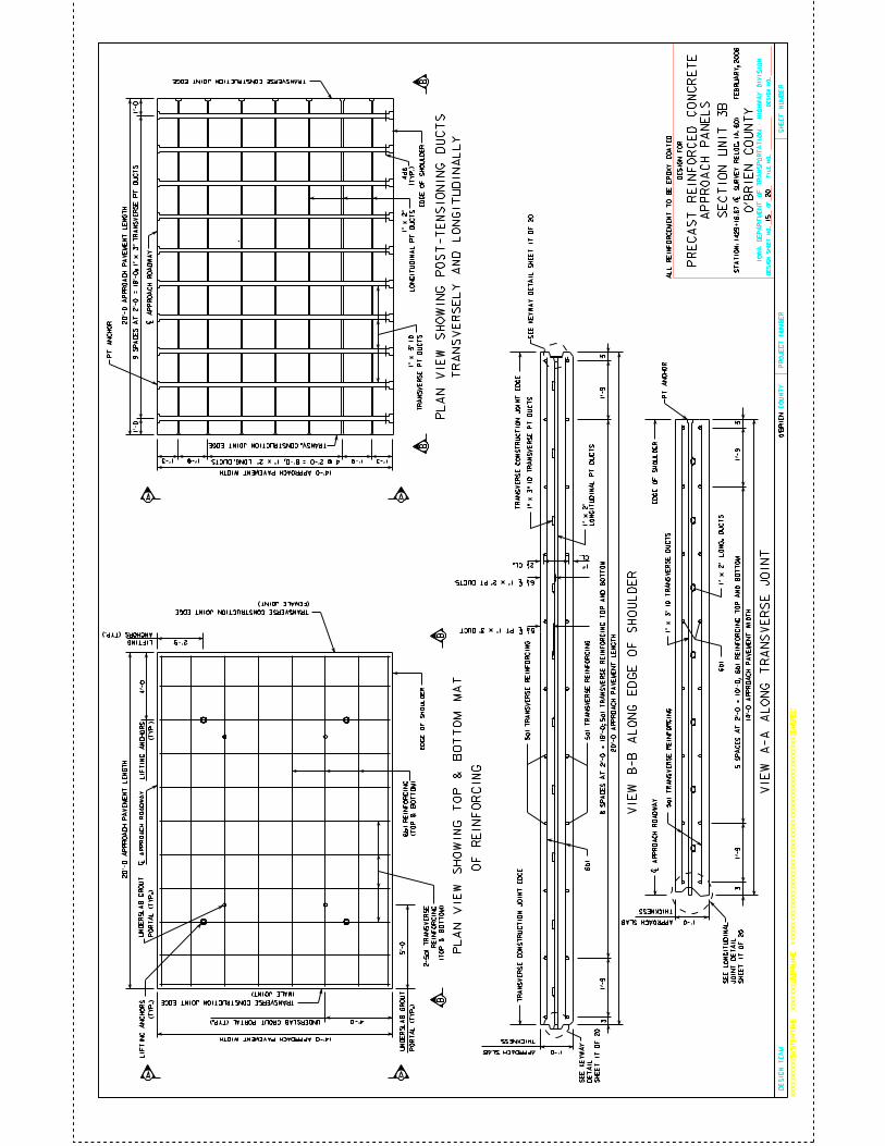
CO
UN
TY
DE
SIG
N S
HE
ET
NO
.O
FD
ES
IGN
NO
.F
ILE
NO
.
IOW
A D
EP
AR
TM
EN
T O
F T
RA
NS
PO
RT
AT
ION
- H
IGH
WA
Y D
IVIS
ION
PR
OJE
CT
NU
MB
ER
SH
EE
T N
UM
BE
R
XX
XX
XX
XX
XX
SY
ST
EM
TIM
EX
XX
XX
XX
US
ER
NA
ME
XX
XX
XX
XX
XX
XX
XX
XX
XX
XX
XX
XX
XX
XX
XX
XX
XX
XX
XX
XX
XX
XX
XX
XX
XX
XX
XD
GN
SP
EC
DE
SIG
N T
EA
M
20
O’B
RIE
N
O’B
RIE
N C
OU
NT
Y
DE
SIG
N F
OR
PR
EC
AS
T R
EIN
FO
RC
ED
CO
NC
RE
TE
ST
AT
IO
N:
14
29
+1
6.6
7 (
| S
UR
VE
Y R
EL
OC
. IA
. 6
0)
F
EB
RU
AR
Y,
20
06
AP
PR
OA
CH
PA
NE
LS
5a1
TR
AN
SV
ER
SE
RE
INF
OR
CIN
G
5a1
TR
AN
SV
ER
SE
RE
INF
OR
CIN
G
VIE
W B
-B A
LO
NG
ED
GE
OF
SH
OU
LD
ER
VIE
W A
-A A
LO
NG
TR
AN
SV
ER
SE
JO
INT
A
BB
A
A
BB
A
1’-0
THICKNESS
| A
PP
RO
AC
H R
OA
DW
AY
14’-
0 A
PP
RO
AC
H P
AV
EM
EN
T W
IDT
H
5a1
TR
AN
SV
ER
SE
RE
INF
OR
CIN
G1
" x
3" I
D T
RA
NS
VE
RS
E D
UC
TS
1’-
93
1’-
93
1’-0
THICKNESS
TR
AN
SV
ER
SE
CO
NS
TR
UC
TIO
N J
OIN
T E
DG
ET
RA
NS
VE
RS
E C
ON
ST
RU
CT
ION
JO
INT
ED
GE
8 S
PA
CE
S A
T 2
’-0 =
16’-0;
5a1 T
RA
NS
VE
RS
E R
EIN
FO
RC
IN
G T
OP
AN
D B
OT
TO
M
20’-
0 A
PP
RO
AC
H P
AV
EM
EN
T L
EN
GT
H
20’-
0 A
PP
RO
AC
H P
AV
EM
EN
T L
EN
GT
H
14’-0 APPROACH PAVEMENT WIDTH
1’-91’-9
1’-
01
’-0
20’-
0 A
PP
RO
AC
H P
AV
EM
EN
T L
EN
GT
H
14’-0 APPROACH PAVEMENT WIDTH
| A
PP
RO
AC
H R
OA
DW
AY
| A
PP
RO
AC
H R
OA
DW
AY
SE
CT
ION
UN
IT 3
B
ED
GE
OF
SH
OU
LD
ER
ED
GE
OF
SH
OU
LD
ER
ED
GE
OF
SH
OU
LD
ER
APPROACH SLAB
TRANSVERSE CONSTRUCTION JOINT EDGE
1’-31’-3
PL
AN
VIE
W S
HO
WIN
G T
OP
& B
OT
TO
M M
AT
PL
AN
VIE
W S
HO
WIN
G P
OS
T-T
EN
SIO
NIN
G D
UC
TS
TR
AN
SV
ER
SE
LY
AN
D L
ON
GIT
UD
INA
LL
Y
2-5
a1
TR
AN
SV
ER
SE
RE
INF
OR
CIN
G
(TO
P &
BO
TT
OM
)
(TO
P &
BO
TT
OM
)
TRANSVERSE CONSTRUCTION JOINT EDGE
(FEMALE JOINT)
TRANSVERSE CONSTRUCTION JOINT EDGE
(MALE JOINT)
3
APPROACH SLAB
PT
AN
CH
OR
3
PT
AN
CH
OR
1’-
91
’-9
TRANSV. CONSTRUCTION JOINT EDGE
4 @ 2’-0 = 8’-0; 1" x 2" LONG. DUCTS
1" x
3" I
D
TR
AN
SV
ER
SE
PT
DU
CT
S
1" x
2"
LO
NG
ITU
DIN
AL
PT
DU
CT
S
9 S
PA
CE
S A
T 2
’-0
= 1
8’-0
; 1
" x
3" T
RA
NS
VE
RS
E P
T D
UC
TS
4d6
(TY
P.)
LIF
TIN
G A
NC
HO
RS
(TY
P.)
4’-0
2’-9LIFTING
ANCHORS (TYP.)
6b
1 R
EIN
FO
RC
ING
5’-0
UN
DE
RS
LA
B G
RO
UT
PO
RT
AL
(T
YP
.)
4’-0UNDERSLAB GROUT PORTAL (TYP.)
UN
DE
RS
LA
B G
RO
UT
PO
RT
AL
(T
YP
.)
LIF
TIN
G A
NC
HO
RS
(TY
P.)
6b
1
2 1/2 CL. 1"
CL.
1" x
3" I
D T
RA
NS
VE
RS
E P
T D
UC
TS
1" x
2"
LO
NG
ITU
DIN
AL
PT
DU
CT
S
OF
RE
INF
OR
CIN
G
AL
L R
EIN
FO
RC
EM
EN
T T
O B
E E
PO
XY
CO
AT
ED
6b
1
5 S
PA
CE
S A
T 2
’-0 =
10’-0;
6b1 R
EIN
FO
RC
IN
G T
OP
AN
D B
OT
TO
M
1" x
2" L
ON
G. D
UC
TS
5 1/4 | PT 1" x 3" DUCT
6 1/4 | 1" x 2" PT DUCTS
SE
E K
EY
WA
Y
DE
TA
IL
SH
EE
T 1
7 O
F 2
0
SE
E L
ON
GIT
UD
INA
L
JO
INT
DE
TA
IL
SH
EE
T 1
7 O
F 2
0
SE
E K
EY
WA
Y D
ET
AIL
SH
EE
T 1
7 O
F 2
0 15
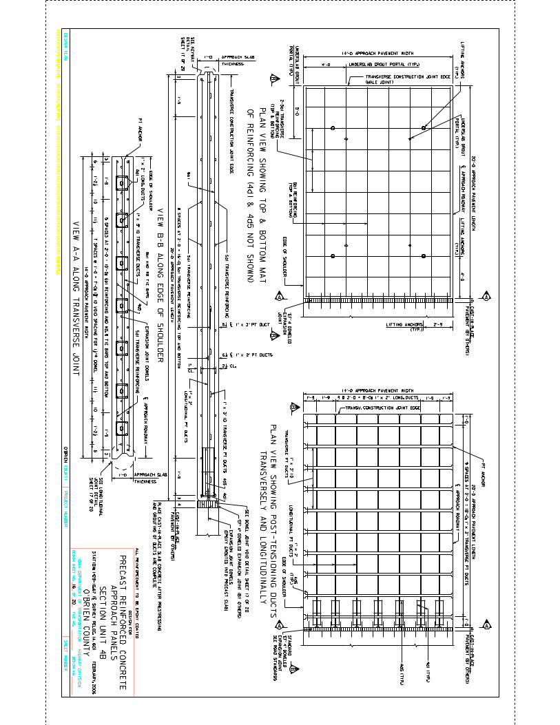
CO
UN
TY
DE
SIG
N S
HE
ET
NO
.O
FD
ES
IGN
NO
.F
ILE
NO
.
IOW
A D
EP
AR
TM
EN
T O
F T
RA
NS
PO
RT
AT
ION
- HIG
HW
AY
DIV
ISIO
N
PR
OJE
CT
NU
MB
ER
SH
EE
T N
UM
BE
R
XX
XX
XX
XX
XX
SY
ST
EM
TIM
EX
XX
XX
XX
US
ER
NA
ME
XX
XX
XX
XX
XX
XX
XX
XX
XX
XX
XX
XX
XX
XX
XX
XX
XX
XX
XX
XX
XX
XX
XX
XX
XX
XX
XD
GN
SP
EC
DE
SIG
N T
EA
M
20
O’B
RIE
N
O’B
RIE
N C
OU
NT
Y
DE
SIG
N F
OR
PR
EC
AS
T R
EIN
FO
RC
ED
CO
NC
RE
TE
ST
AT
IO
N: 1
429+
16.6
7 (
| SU
RV
EY
RE
LO
C. I
A. 6
0) F
EB
RU
AR
Y, 2
006
AP
PR
OA
CH
PA
NE
LS
5a1
TR
AN
SV
ER
SE
RE
INF
OR
CIN
G
5a1
TR
AN
SV
ER
SE
RE
INF
OR
CIN
G
VIE
W B
-B A
LO
NG
ED
GE
OF
SH
OU
LD
ER
VIE
W A
-A A
LO
NG
TR
AN
SV
ER
SE
JO
INT
BB
A
BB
A
1’-0
THICKNESS
| AP
PR
OA
CH
RO
AD
WA
Y
14’-0
AP
PR
OA
CH
PA
VE
ME
NT
WID
TH
5a1
TR
AN
SV
ER
SE
RE
INF
OR
CIN
G1" x
3" ID
TR
AN
SV
ER
SE
DU
CT
S
1’-9
31
’-93
1’-0
THICKNESS
TR
AN
SV
ER
SE
CO
NS
TR
UC
TIO
N J
OIN
T E
DG
E
8 S
PA
CE
S A
T 2
’-0
= 1
6’-0
; 5a1
TR
AN
SV
ER
SE
RE
IN
FO
RC
IN
G T
OP
AN
D B
OT
TO
M
20’-0
AP
PR
OA
CH
PA
VE
ME
NT
LE
NG
TH
20’-0
AP
PR
OA
CH
PA
VE
ME
NT
LE
NG
TH
14’-0 APPROACH PAVEMENT WIDTH
1’-9 1’-9
1’-0
1’-0
20’-0
AP
PR
OA
CH
PA
VE
ME
NT
LE
NG
TH
14’-0 APPROACH PAVEMENT WIDTH
| AP
PR
OA
CH
RO
AD
WA
Y
| AP
PR
OA
CH
RO
AD
WA
Y
SE
CT
ION
UN
IT 4
B
ED
GE
OF
SH
OU
LD
ER
ED
GE
OF
SH
OU
LD
ER
APPROACH SLAB
1’-3 1’-3
PL
AN
VIE
W S
HO
WIN
G T
OP
& B
OT
TO
M M
AT
PL
AN
VIE
W S
HO
WIN
G P
OS
T-T
EN
SIO
NIN
G D
UC
TS
TR
AN
SV
ER
SE
LY
AN
D L
ON
GIT
UD
INA
LL
Y
2-5
a1 T
RA
NS
VE
RS
E
RE
INF
OR
CIN
G
(TO
P &
BO
TT
OM
)
(TO
P &
BO
TT
OM
)
TRANSVERSE CONSTRUCTION JOINT EDGE
(MALE JOINT)
3
APPROACH SLAB
PT
AN
CH
OR
3
PT
AN
CH
OR
1’-9
1’-9
TRANSV. CONSTRUCTION JOINT EDGE
1" x
3" I
D
TR
AN
SV
ER
SE
PT
DU
CT
S
1" x
2"
LO
NG
ITU
DIN
AL
PT
DU
CT
S
9 S
PA
CE
S A
T 2
’-0
= 1
8’-0
; 1" x
3" T
RA
NS
VE
RS
E P
T D
UC
TS
4d
6
(TY
P.)
LIF
TIN
G A
NC
HO
RS
(TY
P.)
4’-0
2’-9
6b
1 R
EIN
FO
RC
ING
5’-0
UN
DE
RS
LA
B G
RO
UT
PO
RT
AL
(TY
P.)
4’-0 UNDERSLAB GROUT PORTAL (TYP.)
UN
DE
RS
LA
B G
RO
UT
PO
RT
AL
(TY
P.)
LIF
TIN
G A
NC
HO
RS
(TY
P.)
6b1
2 1/2 CL.1"
CL.
1" x
3" I
D T
RA
NS
VE
RS
E P
T D
UC
TS
1" x
2"
LO
NG
ITU
DIN
AL
PT
DU
CT
S
AL
L R
EIN
FO
RC
EM
EN
T T
O B
E E
PO
XY
CO
AT
ED
1" x
2" L
ON
G. D
UC
TS
4 @ 2’-0 = 8’-0; 1" x 2" LONG. DUCTS
44
’EF
’ 4 D
OW
EL
ED
EX
PA
NS
ION
JO
INT
66
ED
GE
OF
SH
OU
LD
ER
5 S
PA
CE
S A
T 2
’-0 =
10’-0; 6
b1 R
EIN
FO
RC
IN
G A
ND
NO
. 8 T
IE
BA
RS
TO
P A
ND
BO
TT
OM
EX
PA
NS
ION
JO
INT
DO
WE
LS
(TYP.)
LIFTING ANCHORS
OF
RE
INF
OR
CIN
G (4
d1
& 4
d5
NO
T S
HO
WN
)
4
4d5
4d
1
6b
1 A
ND
#8
TIE
BA
RS
4d5
4d
1
5 1/4 | 1" x 3" PT DUCT
6 1/4 | 1" x 2" PT DUCTS
SE
E K
EY
WA
Y
DE
TA
IL
SH
EE
T 1
7 O
F 2
0
SE
E L
ON
GIT
UD
INA
L
JO
INT
DE
TA
IL
SH
EE
T 1
7 O
F 2
0
16
AA
4d1 (T
YP
.)
4d5 (
TY
P.)
CA
ST
-IN-P
LA
CE
PA
VE
ME
NT
(BY
OT
HE
RS
)
’EF
’ 4" D
OW
EL
ED
EX
PA
NS
ION
JO
INT
(BY
OT
HE
RS
)
SE
E D
OW
EL
JO
IN
T V
OID
DE
TA
IL
SH
EE
T 1
7 O
F 2
0
CA
ST
-IN-P
LA
CE
PA
VE
ME
NT
(BY
OT
HE
RS
)
CA
ST
-IN-P
LA
CE
PA
VE
ME
NT
(BY
OT
HE
RS
)
7 S
PA
CE
S @
1’-0
= 7
’-0; 1
5/8
" ID
VO
ID S
PA
CIN
G F
OR
1 1
/2 "
59
/64
DO
WE
L1
011 1/2
11 1/2 1
0
ST
AN
DA
RD
’EF
’ 4" D
OW
EL
ED
EX
PA
NS
ION
JO
INT
SE
E R
OA
D S
TA
ND
AR
DS
1’-2 1/2 1’-2 1/2
EX
PA
NS
ION
JO
INT
DO
WE
LS
(EP
OX
Y G
RO
UT
ED
INT
O P
RE
CA
ST
SL
AB
)
PL
AC
E C
AS
T-IN
-PL
AC
E S
LA
B C
ON
CR
ET
E A
FT
ER
PR
ES
TR
ES
SIN
G
AN
D G
RO
UT
ING
OF
DU
CT
S A
RE
CO
MP
LE
TE
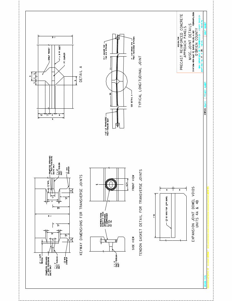
CO
UN
TY
DE
SIG
N S
HE
ET
NO
.O
FD
ES
IGN
NO
.F
ILE
NO
.
IOW
A D
EP
AR
TM
EN
T O
F T
RA
NS
PO
RT
AT
ION
- H
IGH
WA
Y D
IVIS
ION
PR
OJE
CT
NU
MB
ER
SH
EE
T N
UM
BE
R
XX
XX
XX
XX
XX
SY
ST
EM
TIM
EX
XX
XX
XX
US
ER
NA
ME
XX
XX
XX
XX
XX
XX
XX
XX
XX
XX
XX
XX
XX
XX
XX
XX
XX
XX
XX
XX
XX
XX
XX
XX
XX
XX
XD
GN
SP
EC
DE
SIG
N T
EA
M
20
O’B
RIE
N
O’B
RIE
N C
OU
NT
Y
DE
SIG
N F
OR
PR
EC
AS
T R
EIN
FO
RC
ED
CO
NC
RE
TE
ST
AT
IO
N:
1429+
16.6
7 (
| S
UR
VE
Y R
EL
OC
. IA
. 60) F
EB
RU
AR
Y, 2006
AP
PR
OA
CH
PA
NE
LS
GR
OU
T P
OC
KE
T
PT
CO
UP
LE
R
3
3
9
21 1/2 2 1/2
1 1/2
1 1/2
1 1/2
TY
PIC
AL
LO
NG
ITU
DIN
AL
JO
INT
1" x
3" P
T D
UC
T
3
C L
FR
ON
T V
IEW
SID
E V
IEW
NE
OP
RE
NE
/FO
AM
GA
SK
ET
(1
" T
HIC
K
UN
CO
MP
RE
SS
ED
,
1/2
" C
OM
PR
ES
SE
D)
4 1
/4 "
O.D
.
3 1
/4 "
I.D
.
5 3/4
4
5 3/4
TR
UM
PE
TE
D O
PE
NIN
GS
AT
PO
ST
-TE
NS
ION
ING
DU
CT
S O
NL
Y
1 1
/2 "
MIN
.
1 1/2
1/2
2 1/2
1/2
1/2
2 3/8
4 1/4
1 1/2
1/2
1 1/2
1 3/8
TR
UM
PE
TE
D O
PE
NIN
GS
AT
PO
ST
-TE
NS
ION
ING
DU
CT
S O
NL
Y
1/2
" x
4 1
/4 "
59/
64
RE
CE
SS
1" x
2"
PO
ST
-TE
NS
ION
DU
CT
1" x
2"
PO
ST
-TE
NS
ION
DU
CT
4 1/4
" 59/6
4
2%
2%
1"x
3" I
.D.
TR
AN
SV
ER
SE
PO
ST
-TE
NS
ION
DU
CT
P-T
AN
CH
OR
FO
R
TW
O 0
.5" S
TR
AN
DS
2 -
0.5
" G
RA
DE
27
0
PO
ST
-TE
NS
ION
ED
ST
RA
ND
S
1’-0
1 1
/4 "
M
IN.
CH
AM
FE
R
1 1
/4 "
MIN
.
CH
AM
FE
R
1" x
2"
PO
ST
-TE
NS
ION
DU
CT
KE
YW
AY
DIM
EN
SIO
NS
FO
R T
RA
NS
VE
RS
E J
OIN
TS
TE
ND
ON
GA
SK
ET
DE
TA
IL F
OR
TR
AN
SV
ER
SE
JO
INT
S
1’-0
MIS
C.
JO
INT
DE
TA
ILS
DE
TA
IL A
SE
E D
ET
AIL
A
17
6 6
1’-
8
1 5
/8 "
ID
VO
ID F
OR
1 1
/2 "
59
/64
D
OW
EL
UN
IT
S 4
A &
4B
EX
PA
NS
ION
JO
INT
DO
WE
L V
OID
S
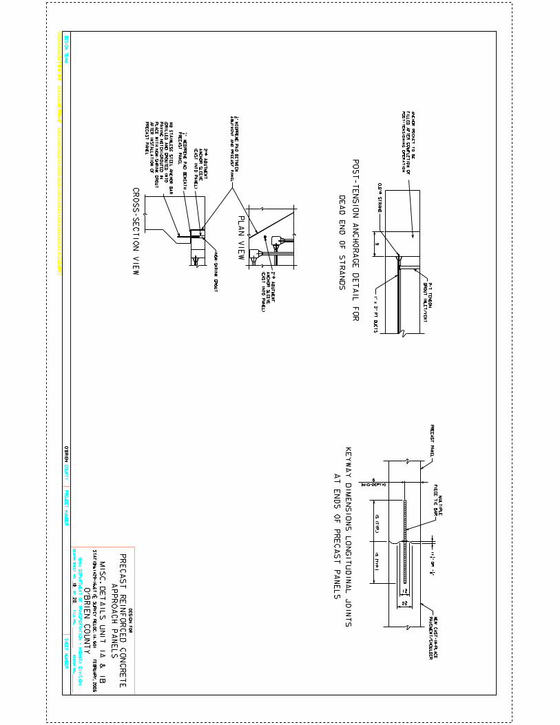
CO
UN
TY
DE
SIG
N S
HE
ET
NO
.O
FD
ES
IGN
NO
.F
ILE
NO
.
IOW
A D
EP
AR
TM
EN
T O
F T
RA
NS
PO
RT
AT
ION
- HIG
HW
AY
DIV
ISIO
N
PR
OJE
CT
NU
MB
ER
SH
EE
T N
UM
BE
R
XX
XX
XX
XX
XX
SY
ST
EM
TIM
EX
XX
XX
XX
US
ER
NA
ME
XX
XX
XX
XX
XX
XX
XX
XX
XX
XX
XX
XX
XX
XX
XX
XX
XX
XX
XX
XX
XX
XX
XX
XX
XX
XX
XD
GN
SP
EC
DE
SIG
N T
EA
M
20
O’B
RIE
N
O’B
RIE
N C
OU
NT
Y
DE
SIG
N F
OR
PR
EC
AS
T R
EIN
FO
RC
ED
CO
NC
RE
TE
ST
AT
IO
N: 1
429+
16.6
7 (
| SU
RV
EY
RE
LO
C. I
A. 6
0) F
EB
RU
AR
Y, 2
006
AP
PR
OA
CH
PA
NE
LS
NE
W C
AS
T-IN
-PL
AC
E
PA
VE
ME
NT
/SH
OU
LD
ER
PR
EC
AS
T P
AN
EL
15
(TY
P.)
15
(TY
P.)
6
(MID-DEPTH)
NO
N-S
HR
INK
GR
OU
T
PL
AN
VIE
W
CR
OS
S-S
EC
TIO
N V
IEW
2" 5
9/6
4 A
BU
TM
EN
T
AN
CH
OR
SL
EE
VE
(CA
ST
INT
O P
AN
EL
)
1/2
" N
EO
PR
EN
E P
AD
BE
NE
AT
H
PR
EC
AS
T P
AN
EL
1/2
" N
EO
PR
EN
E P
AD
BE
TW
EE
N
AB
UT
ME
NT
AN
D P
RE
CA
ST
PA
NE
L
2" 5
9/6
4 A
BU
TM
EN
T
AN
CH
OR
SL
EE
VE
(CA
ST
INT
O P
AN
EL
)
9
PO
ST
-TE
NS
ION
AN
CH
OR
AG
E D
ET
AIL
FO
R
P-T
TE
ND
ON
GR
OU
T IN
LE
T/V
EN
T
AT
EN
DS
OF
PR
EC
AS
T P
AN
EL
S
KE
YW
AY
DIM
EN
SIO
NS
LO
NG
ITU
DIN
AL
JO
INT
S
1+
1/4
" OR
- 1/8
"
#8
ST
AIN
LE
SS
ST
EE
L A
NC
HO
R B
AR
(DR
ILL
ED
AN
D G
RO
UT
ED
INT
O
PA
VIN
G N
OT
CH
) GR
OU
TE
D IN
PL
AC
E W
ITH
NO
N-S
HR
INK
GR
OU
T
AF
TE
R IN
ST
AL
LA
TIO
N O
F
PR
EC
AS
T P
AN
EL
MIS
C. D
ET
AIL
S U
NIT
1A
& 1
B
AN
CH
OR
PO
CK
ET
TO
BE
FIL
LE
D A
FT
ER
CO
MP
LE
TIO
N O
F
PO
ST
-TE
NS
ION
ING
OP
ER
AT
ION
DE
AD
EN
D O
F S
TR
AN
DS
1" x
2" P
T D
UC
TS
0.6
" 59
/64
ST
RA
ND
MU
LT
IPL
E
PIE
CE
TIE
BA
R
1 3/4
2 3/4
18
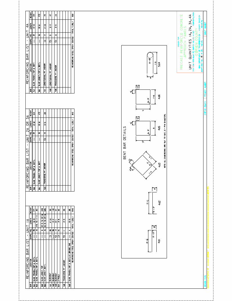
CO
UN
TY
DE
SIG
N S
HE
ET
NO
.O
FD
ES
IGN
NO
.F
ILE
NO
.
IOW
A D
EP
AR
TM
EN
T O
F T
RA
NS
PO
RT
AT
ION
- H
IGH
WA
Y D
IVIS
ION
PR
OJE
CT
NU
MB
ER
SH
EE
T N
UM
BE
R
XX
XX
XX
XX
XX
SY
ST
EM
TIM
EX
XX
XX
XX
US
ER
NA
ME
XX
XX
XX
XX
XX
XX
XX
XX
XX
XX
XX
XX
XX
XX
XX
XX
XX
XX
XX
XX
XX
XX
XX
XX
XX
XX
XD
GN
SP
EC
DE
SIG
N T
EA
M
20
O’B
RIE
N
O’B
RIE
N C
OU
NT
Y
DE
SIG
N F
OR
PR
EC
AS
T R
EIN
FO
RC
ED
CO
NC
RE
TE
ST
AT
IO
N:
1429+
16.6
7 (
| S
UR
VE
Y R
EL
OC
. IA
. 60) F
EB
RU
AR
Y, 2006
AP
PR
OA
CH
PA
NE
LS
WE
IGH
T
LE
NG
TH
S
HA
PE
B
AR
L
OC
AT
ION
N
O.
NO
TE
: A
LL
DIM
EN
SIO
NS
AR
E O
UT
TO
OU
T. D
= P
IN D
IAM
ET
ER
.
BE
NT
BA
R D
ET
AIL
S
5d
44
d3
4d
2
1’-4
1’-4
4 1/2
4 1/2
6
1’-
6
2’-1
1/2
6
D= 2
"
D =
2"
D=
4 3
/4 "
5a1
6b
2
8b3
4d
1
4d2
4d3
5a3
SL
AB
TR
AN
SV
. T
OP
& B
OT
T.
SL
AB
LO
NG
IT.
TO
P
SL
AB
LO
NG
IT. B
OT
T.
6’-1
3’-
85d4
3’-
2
RE
INF
OR
CIN
G S
TE
EL
EP
OX
Y C
OA
TE
D -
TO
TA
L (
LB
S.
)
RE
INF
OR
CIN
G B
AR
LIS
T -
UN
IT 1
A
UN
IT Q
UA
NT
ITIE
S 1
A, 2A
, 3A
, 4A
WE
IGH
T
LE
NG
TH
S
HA
PE
B
AR
L
OC
AT
ION
N
O.
5a1
4d
6
SL
AB
TR
AN
SV
. T
OP
& B
OT
T.
3’-
5
13
’-8
RE
INF
OR
CIN
G S
TE
EL
EP
OX
Y C
OA
TE
D -
TO
TA
L (
LB
S.
)
WE
IGH
T
LE
NG
TH
S
HA
PE
B
AR
L
OC
AT
ION
N
O.
5a1
6b1
4d
1
4d5
SL
AB
TR
AN
SV
. T
OP
& B
OT
T.
3’-
4
13
’-8
RE
INF
OR
CIN
G S
TE
EL
EP
OX
Y C
OA
TE
D -
TO
TA
L (
LB
S.
)
RE
IN
FO
RC
IN
G B
AR
LIS
T -
UN
IT
4A
RE
IN
FO
RC
IN
G B
AR
LIS
T -
UN
IT
2A
OR
3A
6b1
19’-
8
31
4
47
3
23
81
0
4d
63’-
5
10
22
16
1422
16
10
21
19’-
8
4’-
10
45
23
47
31
4
47
3
902
4 1/2
D=
2"
4 1/2
8
7 1/2 4
d5
4 1/2
D=
2"
4 1/2
4
4d6
1’-
0
4d
1
2’-1
1/2
6 1/2
D =
2"
19
SL
AB
LO
NG
IT. T
OP
& B
OT
T
TR
AN
SV
ER
SE
PT
AN
CH
OR
SL
AB
LO
NG
IT. T
OP
& B
OT
T.
LO
NG
ITU
DIN
AL
PT
AN
CH
OR
LO
NG
ITU
DIN
AL
PT
AN
CH
OR
TR
AN
SV
ER
SE
PT
AN
CH
OR
BL
OC
KO
UT
BL
OC
KO
UT
BL
OC
KO
UT
2" 5
9/64
HO
LE
62
57
11
8
90
4’-
10
28
14
16
568 15
83
5a2
46
6
4d
611
25
15’-
9
TR
AN
SV
ER
SE
PT
AN
CH
OR
26
10
13
’-8
37
1
16
’-9
TO
24
’-6
4’0 T
O 1
1’-11
24
8
826
16
’-9
TO
24
’-6
3’-
5
SL
AB
TR
AN
SV
. T
OP
& B
OT
T.
SL
AB
TR
AN
SV
. T
OP
& B
OT
T.
AT
BR
IDG
E E
ND
1946
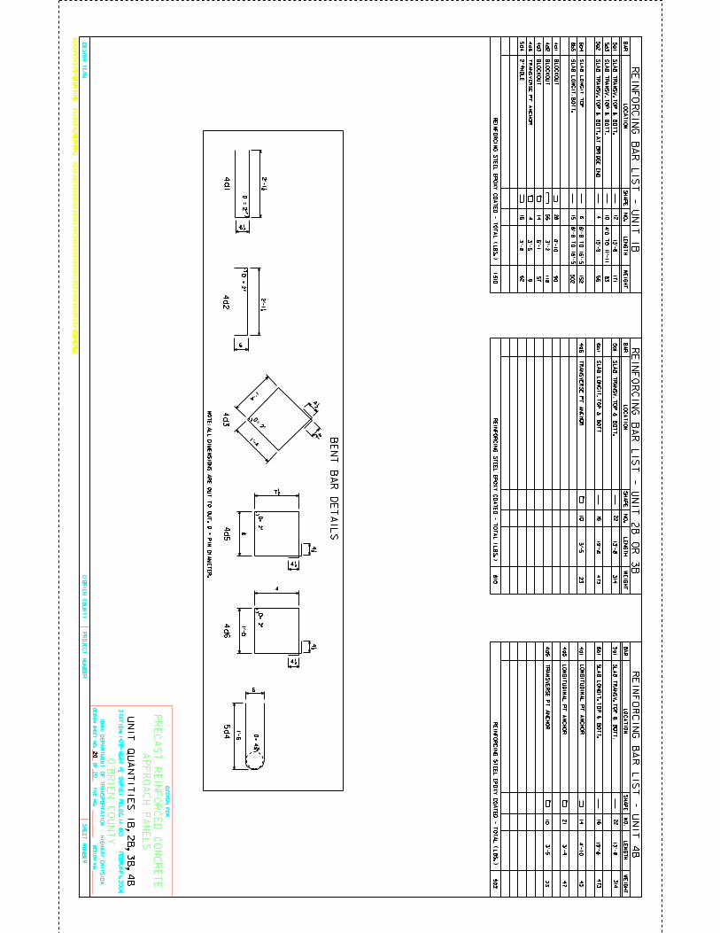
CO
UN
TY
DE
SIG
N S
HE
ET
NO
.O
FD
ES
IGN
NO
.F
ILE
NO
.
IOW
A D
EP
AR
TM
EN
T O
F T
RA
NS
PO
RT
AT
ION
- HIG
HW
AY
DIV
ISIO
N
PR
OJE
CT
NU
MB
ER
SH
EE
T N
UM
BE
R
XX
XX
XX
XX
XX
SY
ST
EM
TIM
EX
XX
XX
XX
US
ER
NA
ME
XX
XX
XX
XX
XX
XX
XX
XX
XX
XX
XX
XX
XX
XX
XX
XX
XX
XX
XX
XX
XX
XX
XX
XX
XX
XX
XD
GN
SP
EC
DE
SIG
N T
EA
M
20
O’B
RIE
N
O’B
RIE
N C
OU
NT
Y
DE
SIG
N F
OR
PR
EC
AS
T R
EIN
FO
RC
ED
CO
NC
RE
TE
ST
AT
IO
N: 1
429+
16.6
7 (
| SU
RV
EY
RE
LO
C. I
A. 6
0) F
EB
RU
AR
Y, 2
006
AP
PR
OA
CH
PA
NE
LS
WE
IGH
T
LE
NG
TH
S
HA
PE
B
AR
L
OC
AT
ION
N
O.
NO
TE
: AL
L D
IME
NS
ION
S A
RE
OU
T T
O O
UT
. D =
PIN
DIA
ME
TE
R.
BE
NT
BA
R D
ET
AIL
S
5d
44
d3
4d
2
1’-41’-4
4 1/2 4 1/2
6
1’-6
2’-1 1/2
6
D= 2"
D =
2"
D=
4 3/4 "
5a1
6b
4
8b5
4d
1
4d2
4d3
5a2
SL
AB
TR
AN
SV
. TO
P &
BO
TT
. AT
BR
IDG
E E
ND
SL
AB
LO
NG
IT. T
OP
SL
AB
LO
NG
IT. B
OT
T.
6’-1
3’-5
4d
6
15’-9
RE
INF
OR
CIN
G S
TE
EL
EP
OX
Y C
OA
TE
D - T
OT
AL
( LB
S. )
RE
INF
OR
CIN
G B
AR
LIS
T - U
NIT
1B
UN
IT Q
UA
NT
ITIE
S 1
B, 2
B, 3
B, 4
B
WE
IGH
T
LE
NG
TH
S
HA
PE
B
AR
L
OC
AT
ION
N
O.
5a1
4d
6
SL
AB
TR
AN
SV
. TO
P &
BO
TT
.
3’-5
13
’-8
RE
INF
OR
CIN
G S
TE
EL
EP
OX
Y C
OA
TE
D - T
OT
AL
( LB
S. )
WE
IGH
T
LE
NG
TH
S
HA
PE
B
AR
L
OC
AT
ION
N
O.
5a1
6b1
4d
1
4d5
SL
AB
TR
AN
SV
. TO
P &
BO
TT
.
3’-4
13
’-8
RE
INF
OR
CIN
G S
TE
EL
EP
OX
Y C
OA
TE
D - T
OT
AL
( LB
S. )
RE
IN
FO
RC
IN
G B
AR
LIS
T -
UN
IT
4B
RE
IN
FO
RC
IN
G B
AR
LIS
T -
UN
IT
2B
OR
3B
6b1
19’-8
31
4
47
3
23
81
0
4d
63’-5
10
22
16
14 22
16
10
21
19’-8
4’-1
045
23
47
31
4
47
3
902
4 1/2
D=
2"
4 1/2
8
7 1/2 4
d5
4 1/2
D=
2"
4 1/2
4
4d6
1’-0
4d
1
2’-1 1/2
6 1/2
D =
2"
12
15 856
28 4
57
144
4’-1
09
0
5a3
10
11
89
5d4
16
62
3’-8
20
SL
AB
LO
NG
IT. T
OP
& B
OT
T.
TR
AN
SV
ER
SE
PT
AN
CH
OR
SL
AB
LO
NG
IT. T
OP
& B
OT
T.
LO
NG
ITU
DIN
AL
PT
AN
CH
OR
LO
NG
ITU
DIN
AL
PT
AN
CH
OR
TR
AN
SV
ER
SE
PT
AN
CH
OR
BL
OC
KO
UT
BL
OC
KO
UT
BL
OC
KO
UT
TR
AN
SV
ER
SE
PT
AN
CH
OR
2" 59/64 HO
LE
3’-2
83
66
SL
AB
TR
AN
SV
. TO
P &
BO
TT
.
SL
AB
TR
AN
SV
. TO
P &
BO
TT
.
13
’-8171
4’0 T
O 1
1’-11
15
2
50
2
8’-8 T
O 1
6’-5
8’-8 T
O 1
6’-5
1310