Embed Size (px)
Citation preview

95 Improving Bridges with Prefabricated Precast Concrete Systems
3 PERFORMANCE, CHALLENGES, AND LESSONS LEARNED
3.1 OVERVIEW
This chapter presents (a) the causes of premature deterioration, potential measures to enhance
durability performance of the earlier ABC implementations, and recommendations for future
research and (b) the challenges and lessons learned from review of ABC projects.
3.2 FIELD PERFORMANCE OF BRIDGES CONSTRUCTED USING ABC TECHNIQUES
Performance of (a) full-depth deck panel systems, (b) bridges constructed using Self
Propeller Modular Transporters (SPMT) or the slide-in techniques, and (c) side-by-side box-
beam systems were reviewed. Appendix C provides description of each bridge, design
details (where available), durability performance of full-depth deck panel systems and the
bridges constructed using SPMTs or slide-in. This section presents the causes of premature
deterioration, potential measures to enhance durability performance of the prefabricated
bridge systems, and implementation recommendations.

96 Improving Bridges with Prefabricated Precast Concrete Systems
3.3 CAUSES AND METHODS TO ABATE PREMATURE DETERIORATION OF FULL-DEPTH DECK PANEL SYSTEMS
Cause-1: Leakage through the transverse joints and shear pockets in full-depth deck panel
systems (Culmo 2010).
Measures Description (Culmo 2010)
Avoid welded tie plate connections at transverse joints.
The live load at the middle portion of the deck panel will induce transverse as well as longitudinal bending in the deck panel. As the welded tie connection does not have adequate moment capacity, it may lead to failure of the connection. Moreover, a thin polymer overlay will not be sufficient to prevent the leakage in this situation.
Use post-tensioning in conjunction with a grouted shear key at transverse connection.
Minor shrinkage of shear key grout during the construction may develop cracks. Longitudinal post-tensioning after the grouting operation and using an overlay could prevent leakage.
Use superior quality grouting material, an effective curing method, and a superior quality overlay.
Gaps and cracks in the grouted joints and grouted shear pockets may allow active leakage. These may be developed due to minor shrinkage of the grout after placement. The minor shrinkage in the grout may be due to quality of grout and/or lack of effective curing. Moreover, frequent exposure of the grouting material with de-icing salts could result in joint degradation and leakage. The use of waterproofing membrane and a superior quality overlay could prevent leakage.
Cause-2: Lack of post-tensioning to secure the tightness of the joints in a full-depth deck
panel system (Sullivan 2003).
Measures Description
Longitudinal post-tensioning
The precast concrete panels should be post-tensioned longitudinally to secure tightness of transverse joints, thus avoiding leakage (Issa et al. 1995b).
Treating joints with caulking material
Caulking material can be used for patching the openings in the joints; thus preventing leaching action through joints and preventing deposits and stains forming (Sullivan 2003).
Grouting joints with magnesium phosphate
Self-leveling Magnesium phosphate grout can be applied at temperatures as low as 15° F. Grout can gain a compressive strength of 5000 psi within 3 hours and flexural strength of 600 psi at 24 hrs along with a 600 psi slant shear bond strength (Sullivan 2003).
Proper shear key connection
A shear key should be female-to-female type with at least 0.25 in. opening at bottom to allow any panel irregularities. The joints in which panels are in contact at the bottom should not be used (Issa et al. 1995b; Issa et al. 2007).

97 Improving Bridges with Prefabricated Precast Concrete Systems
Cause-3: Leakage through cracks at the cast-in-place closure pours in a full-depth deck panel
system (Culmo 2010).
Measures Description (Culmo 2010)
Use concrete material which has very low shrinkage and is consistent with thermal behavior of the deck panels.
Cracking is likely at the interface of the closure pour with the precast deck panels which are fabricated in a prefabrication plant. This aspect is magnified when high early strength concrete is used in the closure pour, since high early strength concrete tends to shrink more than conventional concrete. Moreover, the thermal behavior of closure pour concrete should be equivalent to the deck panels, since inconsistent thermal behavior of the deck panels with closure pour may lead to cracks, thus leakage. Using waterproofing membrane and a superior quality overlay may alleviate this issue.
Cause-4: Insufficient stiffness of the bridge superstructure results in increased strain values
in top and bottom portions of beam, thus affecting the panel-beam connection integrity.
Cause-5: Limited numbers of shear connectors are also a factor that affects the beam-panel
connection integrity as the compressive force is likely to exceed the shear strength provided
by the shear connectors.
Cause-6: Lack of composite action between deck panels and beams will result in slippage at
the interface (Smith-Pardo et al. 2003).
Measures Description
Use of shear studs
Shear studs can be used for connecting precast concrete panels with supporting system through shear connection pockets. But a proper construction procedure of providing haunches and considering dimensional irregularities should be maintained to obtain satisfactory results (Issa et al. 1995b; Issa et al. 2007).
Consider a supporting system made of precast concrete
Use of precast concrete supporting system, which is stiffer than a steel supporting system, helps in reducing problems encountered in bridge decks (Issa et al. 1995b; Issa et al. 2007).
98 Improving Bridges with Prefabricated Precast Concrete Systems
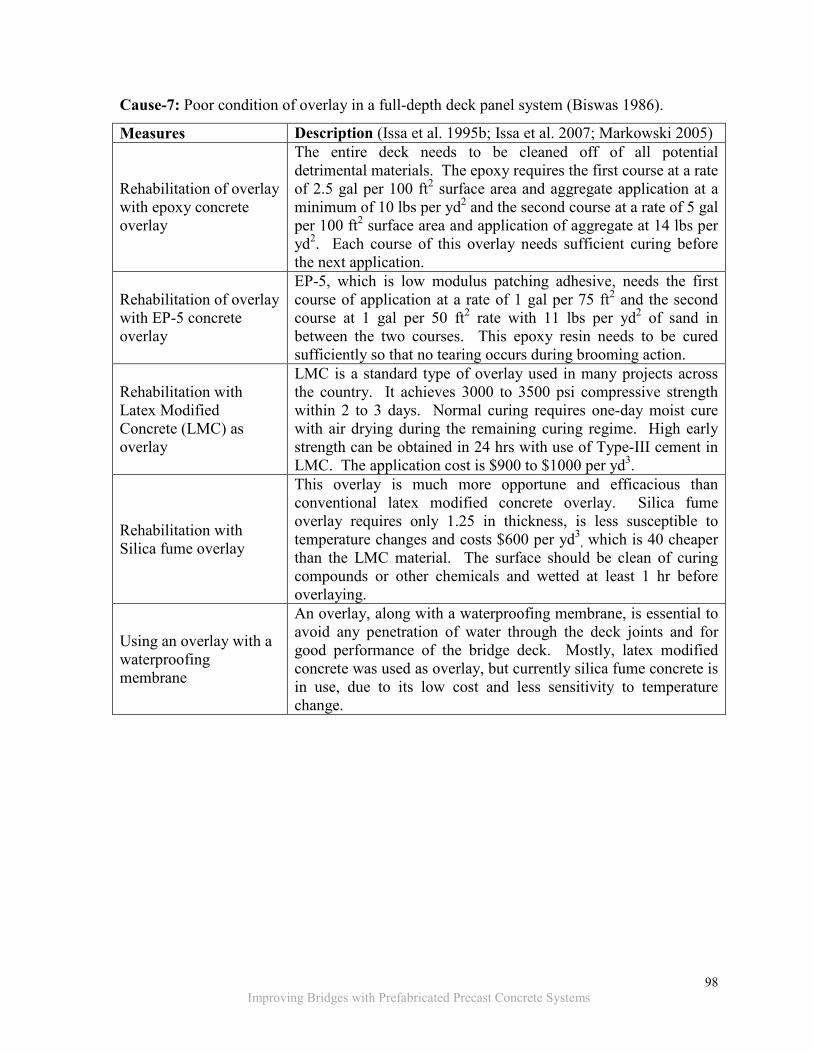
Cause-7: Poor condition of overlay in a full-depth deck panel system (Biswas 1986).
Measures Description (Issa et al. 1995b; Issa et al. 2007; Markowski 2005)
Rehabilitation of overlay with epoxy concrete overlay
The entire deck needs to be cleaned off of all potential detrimental materials. The epoxy requires the first course at a rate of 2.5 gal per 100 ft2 surface area and aggregate application at a minimum of 10 lbs per yd2 and the second course at a rate of 5 gal per 100 ft2 surface area and application of aggregate at 14 lbs per yd2. Each course of this overlay needs sufficient curing before the next application.
Rehabilitation of overlay with EP-5 concrete overlay
EP-5, which is low modulus patching adhesive, needs the first course of application at a rate of 1 gal per 75 ft2 and the second course at 1 gal per 50 ft2 rate with 11 lbs per yd2 of sand in between the two courses. This epoxy resin needs to be cured sufficiently so that no tearing occurs during brooming action.
Rehabilitation with Latex Modified Concrete (LMC) as overlay
LMC is a standard type of overlay used in many projects across the country. It achieves 3000 to 3500 psi compressive strength within 2 to 3 days. Normal curing requires one-day moist cure with air drying during the remaining curing regime. High early strength can be obtained in 24 hrs with use of Type-III cement in LMC. The application cost is $900 to $1000 per yd3.
Rehabilitation with Silica fume overlay
This overlay is much more opportune and efficacious than conventional latex modified concrete overlay. Silica fume overlay requires only 1.25 in thickness, is less susceptible to temperature changes and costs $600 per yd3
, which is 40 cheaper than the LMC material. The surface should be clean of curing compounds or other chemicals and wetted at least 1 hr before overlaying.
Using an overlay with a waterproofing membrane
An overlay, along with a waterproofing membrane, is essential to avoid any penetration of water through the deck joints and for good performance of the bridge deck. Mostly, latex modified concrete was used as overlay, but currently silica fume concrete is in use, due to its low cost and less sensitivity to temperature change.

99 Improving Bridges with Prefabricated Precast Concrete Systems
Cause-8: Deep shear cracks near the edge of the panels in a full-depth deck panel system
(Markowski, 2005).
Measures Description
Treat Crack with High Molecular Weight Methacrylate (HMWM).
HMWM can be used both for crack sealing and treatment of concrete surfaces. This can fill 0.25 to 0.50 inch cracks in depth and can be used for situations of randomly oriented cracks where grouting and sealing are not obvious. Shot-blasting is necessary prior to placing HMWM (Issa et al. 1995b; Issa et al. 2007). Panel capacity can be increased with prestressing.
Cause-9: Punching shear is a likely mechanism causing failure in full-depth deck panel
systems that are continuous over girders and subjected to significant amount of traffic
(Sullivan 2003).
Measures Description
Controlling traffic volume
The structural behavior of a bridge is significantly affected by the traffic volume. Hence, the traffic volume should be restricted to design volume to keep the deck in good condition (Issa et al. 1995b).
Use of a prestressed deck panel may alleviate this problem.
Cause-10: Stress due to bending while handling is considered a cause for development of
cracks in panels (Markowski 2005).
Measures Description
Transverse prestressing
Precast concrete panels require a sufficient amount of transverse strength during handling to prevent cracks being developed internally during the process, which may develop to be visible over the surface. Thus, prestressing during fabrication of precast concrete panels is required (Issa et al. 2007, Markowski 2005).

100 Improving Bridges with Prefabricated Precast Concrete Systems
Cause-11: Failure of connection at the approach slab and bridge deck interface (Culmo
2010).
Measures Description (Culmo 2010)
Using cast-in-place closure pours instead of drilled pin or welded tie connections
Cast-in-place closure pours proved to be more durable than the drilled pin connection and welded tie connection. The joint at the approach slab and bridge deck interface should resist the live load impacts and rotational moment developed due to settlement of the sleeper slab. The drilled pin and welded tie connections failed to withstand these effects, causing failure, thus developing potholes at the approach of the bridge.
3.4 CAUSES AND METHODS TO ABATE PREMATURE DETERIORATION OF
BRIDGES MOVED USING SPMT
Cause-12: Diagonal cracks near the ends of the decks that are placed using SPMT (Culmo
2010).
Measures Description (Culmo 2010)
Using the pick-point casting method for field casting
The cracks in the bridge deck are highly dependent on the casting method. When the bridge deck is field cast by supporting at the girder ends and lifted using a SPMT at interior pick-points rather than the girder ends, the stresses developed in the deck will surpass the cracking limits of concrete. The cracks developed may lead to active leaking and affect the long-term performance of the structure. Moreover, a thin polymer overlay will not be sufficient to prevent the moisture ingress in this situation. Therefore, casting the deck by supporting the girders at interior pick-point locations is recommended when an SPMT is used to move the bridge.
Providing adequate time for curing and casting end-diaphragms and parapets once deck is hardened enough to sustain the stresses due to shrinkage
The cast-in-place concrete decks (conventional and the ones moved using SPMT) showed signs of cracking due to shrinkage in the deck. High early strength concrete is used in these bridge decks. The use of high early strength concrete tends to shrink more than conventional concrete and may magnify the cracking issue. This issue could be alleviated by allowing sufficient time for the deck to cure and shrink before casting concrete end-diaphragms and parapets.

101 Improving Bridges with Prefabricated Precast Concrete Systems
3.5 CAUSES AND METHODS TO ABATE PREMATURE SIDE-BY-SIDE BOX-BEAM DETERIORATION
The side-by-side box-beam belongs to the first generation of Accelerated Bridge
Construction (ABC) because it eliminates the cast-in-place concrete deck formwork; thus, it
accelerates the construction while minimizing the disruption to traffic. Further, the
construction can be accelerated using an overlay on the bridges with a low volume of traffic
instead of using a cast-in-place concrete deck. The bridge configuration has already been
implemented in recent projects under the context of ABC; two examples are the Davis
Narrows Bridge in Maine and the Mill Street Bridge in New Hampshire (Russel 2009;
Stamnas and Whittemore 2005). In recent years, the durability and safety of this bridge type
have also become a concern. The concern was due to longitudinal deck surface cracking
reflecting from the longitudinal joints between beams. These cracks permit ingress of
surface runoff that gets trapped within the shear key zones leading to concealed corrosion of
reinforcement as well as prestressing strands. The corrosion activity remains concealed until
cracking, delamination, or spalling occur.
NCHRP Synthesis 393 (Russell 2009), which documents transverse connection details used
by North American highway agencies, was initiated due to the renewed interest of utilizing
side-by-side box-beam bridges for accelerated construction. Significant recommendations of
Synthesis 393 include full-depth grouted shear keys, use of transverse post-tensioning,
incorporating a cast-in-place concrete deck, and a seven-day moist curing of the deck
(Russell 2009). Most recommendations are from Michigan practice, except the use of shear
key grout with high bond strength and specific grout curing procedures. Unfortunately, with
full-depth shear keys, high levels of transverse post-tensioning, and 6 in. thick cast-in-place
concrete decks, Michigan still experiences reflective longitudinal deck cracking. Inspection
of a bridge under construction showed that the grout-beam interface cracking develops within
a couple of days after grouting and well before the bridge is opened to traffic (Aktan et al.
2009). Michigan transverse post-tensioning design is based on an empirical approach and
uses a much greater force magnitude compared to similar practices in other states. In
addition, Ulku et al. (2010) demonstrated the ineffectiveness of post-tensioning applied
through discrete diaphragms in controlling stresses developed in the bridge deck under
thermal loads.

102 Improving Bridges with Prefabricated Precast Concrete Systems
After conducting a comprehensive review of the MDOT research reports RC-1470 and RC-
1527 (Aktan et al. 2005 and Aktan et al. 2009), on reflective deck cracks, the following facts
are derived:
1. Longitudinal reflective deck cracking is common to all side-by-side box-beam
bridges, irrespective of age.
2. Shear key is intact, but cracks appear along the beam-shear key interface within two
to three days upon grouting the joints.
3. Reflective deck cracks appeared within the first 15 days following deck placement.
4. Reflective deck cracks were first documented above the supports (abutments).
5. Reflective cracks initiated from the top of the deck and propagated through the
thickness.
3.6 CHALLENGES AND LESSONS LEARNED
Fourteen ABC related activities were reviewed and summarized in Appendix D. After
analyzing the challenges and lessons learned from each of the reviewed projects, they were
consolidated and categorized into three major topics: project planning and design, precast
element fabrication, and construction operations and tolerances.
3.6.1 Project Planning and Design
• Effective communication, collaboration, and coordination between the designer,
contractor, and fabricator are key elements to mitigate the risks, identify and revise
the methods of construction, and deliver the project on time.
• Pre-event meetings help in examining the steps involved in the construction phase.
• Careful planning of construction operations is essential for the successful completion
of an accelerated bridge construction project.
• While ABC projects may initially cost more, the savings in user costs more than
compensate for the initial investment. Furthermore, as ABC projects become
commonplace, the costs will become competitive with conventional construction
methods.
• Preparing a contingency plan for unforeseen site conditions during construction is
useful to ensure on-time project delivery. The plan will need to address specification

103 Improving Bridges with Prefabricated Precast Concrete Systems
limitations to allow for flexibility in the selection of materials and construction
methods that can accelerate the completion of construction and improve
workmanship.
• An emergency response plan is useful to have and needs to delineate the decision
making authority, communication protocols, and reporting relationship. This plan
must include and clearly define an emergency response checklist, contact
information, contracting alternatives, information sharing, and decision making
hierarchy.
• To ensure design requirements are met, it is essential to develop protocols for
inspection procedures and site visitations.
• Incentive and disincentive provisions will encourage the contractor to expedite the
construction process.
• Using the design-build delivery approach can add further time reduction for
accelerated bridge construction projects.
• All stakeholders need to be involved during the construction process.
• Having only one precast contractor for all pre-fabricated elements will provide a more
efficient construction process.
• Involving the heavy lift contractor during design will facilitate the construction
process.
• The existing structure load capacity is an important factor in selecting the
construction method, particularly when allowing the placement of equipment on the
existing structure.
• The staging area for the Self-Propelled Modular Transporter (SPMT) system, when
used, needs to be planned properly.
• Carefully evaluate the capability of the local concrete supplier when specifying
special concrete mixes.
• During design, identify the grout to be used and consider application limitations when
developing connection details.
• Include a pre-approved grout or demand specific information in special provisions to
identify the exact type of grout to be used in the project rather than listing “non-
shrink grout.”

104 Improving Bridges with Prefabricated Precast Concrete Systems
• The designer and contractor may work together on developing connection details.
3.6.2 Precast Element Fabrication
• Using prefabricated elements minimizes the construction time and traffic impacts,
and it improves safety of motorists and workers in the work zone.
• Standardizing the size of the precast components can improve the efficiency of
installation in accelerated construction.
• Precast units need to be monitored during fabrication and post-tensioning operations.
• Consider using larger precast elements which will reduce the time and cost of
fabrication, delivery, and erection.
• Properly sizing substructure elements allows efficient installation.
• Fabrication of components at the job site, or at a nearby location, will reduce the
construction cost and the impact of load restrictions.
• Contractors need to investigate economical alternatives for temporary structures,
supports, formwork, and material.
• Late submittal of shop drawings tends to push back the project completion data.
3.6.3 Construction Operations and Tolerances
• The SPMT can be used in bridge construction as well as bridge removal for
demolition.
• A lift test prior to the scheduled move is needed to avoid operational delays.
• Simple connection details and lighter sections are needed to prevent the difficulties of
placing pier caps on columns.
• Grout connection details need to be reviewed with special attention to the grouting
operation.
• Since prestress shortening is not well controlled, fitting the alignment pins into the
pier caps is a challenge (i.e., pier cap to column connection).
• Simple and durable connection details at the abutments need to be developed.
• The impact of missing shear connectors needs to be evaluated due to the difficulty of
drilling girder flanges when there is a misalignment. Designers need to consider
providing more flexible connection mechanisms.

105 Improving Bridges with Prefabricated Precast Concrete Systems
• Simple connection details at the foundation and abutment need to be developed
minimizing required grouting efforts.
• Consider using epoxy polymer deck overlay when precast elements are used.
• Consider specifying material properties and applicable evaluation methods (i.e.,
historical data or testing).

Improving Bridges with Prefabricated Precast Concrete Systems
Intentionally left blank

106 Improving Bridges with Prefabricated Precast Concrete Systems
4 THE MICHIGAN ACCELERATED BRIDGE CONSTRUCTION DECISION-MAKING (Mi-ABCD) TOOL
4.1 OVERVIEW State-of-the-art decision making models were reviewed, and the shortcomings of the existing models are documented in Chapter 2. To overcome the limitations in the available decision-making processes, a multi-criteria decision-making process and a guided software program were developed. The software, titled Michigan Accelerated Bridge Construction Decision-Making (Mi-ABCD) tool, evaluates the Accelerated Bridge Construction (ABC) vs. Conventional Construction (CC) alternatives for a particular project. The process incorporates project-specific data with user-cost and life-cycle cost models to provide input to the decision makers with quantitative data. The software is developed using Microsoft Excel and Visual Basic for Applications (VBA) scripts. A user manual is developed for the software and is presented in Appendix E. The multi-criteria decision-making process discussed in this chapter provides solutions to all the issues raised by the mid-north regional state DOTs related to ABC decision-making and cost justification which are listed in the Mid-North Regional Peer-to-Peer Exchange Final Report (FHWA 2012). This chapter presents an overview of the software and its application for a specific bridge site. Also, a brief summary is presented comparing the capabilities and advances of Mi-ABCD with the software developed through a pool fund study by the Oregon State University which is commonly used for making ABC decisions.
4.2 THE Mi-ABCD PROCESS
4.2.1 Sample Popup Menus and Datasheet
The VBA’s Graphical User Interface (GUI) forms are utilized to interact with the user. These
forms are termed as Pop-up Menus (Figure 4-1-a and b), and the Excel sheets that are
customized for user input are termed as Datasheets (Figure 4-1-c). The main features of the
pop-up menu are to provide (1) Command buttons, (2) Dropdown menus, (3) Tabs, (4) Text
fields, (5) Check boxes, and (6) an Additional information button ( ) (Figure 4-1-a and b).
The most commonly used features are the command buttons and dropdown menus. The

107 Improving Bridges with Prefabricated Precast Concrete Systems
primary features of a datasheet are (1) Command buttons, (2) Dropdown menus, and (3) Data
input fields (Figure 4-1-c).
(a)
(b)
(c)
Figure 4-1. Sample popup menus and datasheet
4.2.2 User Menus
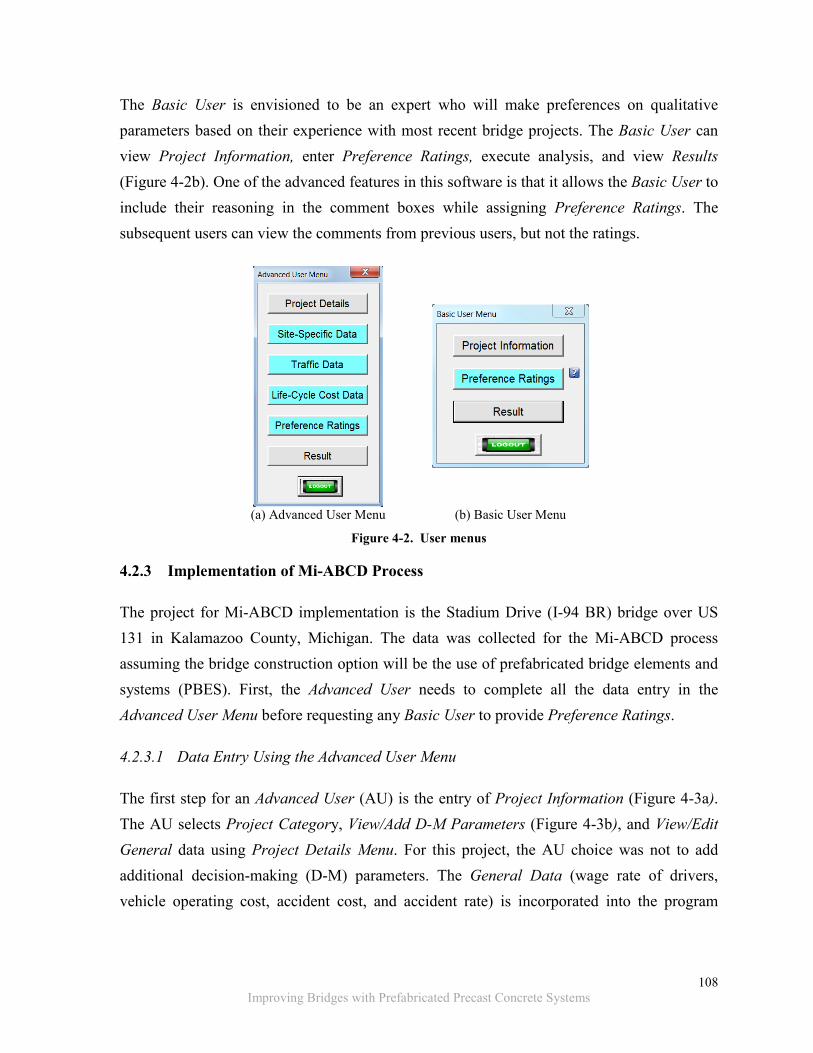
The software allows data entry for two user types; Advanced User and Basic User. The Advanced User is generally envisioned to be the project manager who is familiar with the project specifics of site-specific data, cost estimates, traffic data, and construction methodologies. The Advanced User enters and/or edits Project Details, Site-Specific Data, Traffic Data, Life-Cycle Cost Data, and Preference Ratings. Finally, the Advanced User can execute data analysis and view Results. The Advanced User Menu (Figure 4-2a) includes the command buttons for entering and editing data, data analysis, and viewing results. In order to execute the decision-making process, the Advanced User must complete all the data entry steps before any Basic User can use the program.
Data Input Fields
Dropdown Menus
Command Button
108 Improving Bridges with Prefabricated Precast Concrete Systems
The Basic User is envisioned to be an expert who will make preferences on qualitative parameters based on their experience with most recent bridge projects. The Basic User can view Project Information, enter Preference Ratings, execute analysis, and view Results (Figure 4-2b). One of the advanced features in this software is that it allows the Basic User to include their reasoning in the comment boxes while assigning Preference Ratings. The subsequent users can view the comments from previous users, but not the ratings.
(a) Advanced User Menu (b) Basic User Menu
Figure 4-2. User menus
4.2.3 Implementation of Mi-ABCD Process
The project for Mi-ABCD implementation is the Stadium Drive (I-94 BR) bridge over US 131 in Kalamazoo County, Michigan. The data was collected for the Mi-ABCD process assuming the bridge construction option will be the use of prefabricated bridge elements and systems (PBES). First, the Advanced User needs to complete all the data entry in the Advanced User Menu before requesting any Basic User to provide Preference Ratings.
4.2.3.1 Data Entry Using the Advanced User Menu
The first step for an Advanced User (AU) is the entry of Project Information (Figure 4-3a). The AU selects Project Category, View/Add D-M Parameters (Figure 4-3b), and View/Edit General data using Project Details Menu. For this project, the AU choice was not to add additional decision-making (D-M) parameters. The General Data (wage rate of drivers, vehicle operating cost, accident cost, and accident rate) is incorporated into the program

109 Improving Bridges with Prefabricated Precast Concrete Systems
knowledgebase and does not require frequent changes. Hence, the AU’s choice was not to change General Data for this project.
(a) Project Information
(b) Decision-Making Parameters for Highway over Highway Project
Figure 4-3. (a) Project information and (b) decision-making parameters for highway over highway project
The second step by the AU is to enter Site-Specific Data (Figure 4-4a), Traffic-Data (Figure 4-4b), and the Life-Cycle Cost Data (Figure 4-5) using the command buttons in the Advanced User Menu shown in Figure 4-2a.

110 Improving Bridges with Prefabricated Precast Concrete Systems
(a)
(b)
Figure 4-4. Site specific data and traffic data

111 Improving Bridges with Prefabricated Precast Concrete Systems
Figure 4-5. Life-cycle cost data
The third step by the AU is to enter their Preference Ratings (Figure 4-6). The user can
include their reasoning for the ratings in a text box adjacent to the rating box. Figure 4-6
shows the comments and the Preference Ratings entered by the AU as User-1. Once the AU
data entry is complete and set for Preference Ratings as User-1, the data need to be saved.
Following, AU exits, the program with the data is forwarded to experts who will access Mi-
ABCD as Basic Users (BUs) to enter their Preference Ratings. The subsequent BUs will be
able to see the comments provided in the Preference Rating datasheet by the previous users.
Only the AU is allowed to see the Preference Ratings together with the comments provided
by the users. Once the BUs enter their Preference Ratings, they can perform the analysis by
clicking the UserX-OK button (e.g. User1-OK button shown in Figure 4-6). The analysis
results are viewed by clicking the Result button in the user menu (Figure 4-2). Figure 4-7
shows Preference Ratings entered by the third user together with the comments from the two
previous users.
Figure 4-8 shows the analysis results in three formats: a pie chart, a bar chart, and a line chart. Pie charts describe the upper and lower bound results between the “users.” As shown in Figure 4-8, the ABC upper bound preference rating is 77%, and the lowest bound is 63%. The chart on the right shows distribution of major-parameter preferences from respective users. As an example, the User-1 preference is heavily weighted on the cost parameter (i.e., 38%). That is 30% for ABC and 8% for CC. The cost values are graphically represented in the chart below. Further, the results are shown in a tabular format (Figure 4-9). The first two

112 Improving Bridges with Prefabricated Precast Concrete Systems
rows under cost parameter shows the contribution of cost from User-1 preference (i.e., 8% and 30%) to the overall preference for CC and ABC (i.e., 31% and 69%).
Figure 4-6. Preference ratings and comments provide by User-1

113 Improving Bridges with Prefabricated Precast Concrete Systems
Figure 4-7. User-3 provides Preference Ratings while observing previous users’ comments

114 Improving Bridges with Prefabricated Precast Concrete Systems
Figure 4-8. Results in chart format

115 Improving Bridges with Prefabricated Precast Concrete Systems
Figure 4-9. Results in tabular format

116 Improving Bridges with Prefabricated Precast Concrete Systems
4.3 Mi-ABCD CAPABILITIES AND ADVANCEMENTS
Doolen (2011) developed a Planning Phase Decision Tool for ABC under a pool fund study
with the support from the Federal Highway Administration (FHWA). Even though the tool is
developed using the Analytical Hierarchy Process (AHP), the decision makers have to assign
preference ratings by making pair-wise comparisons of all decision parameters (Figure 4-10).
Further, the users cannot provide comments regarding their preferences. Additionally,
supportive data is not provided to help guide the user preferences. Hence, the decisions are
not properly articulated, and the aggregate preferences by the users may not yield a coherent
decision.
Figure 4-10. Interface of the decision tool developed by Doolen (2011)
The Mi-ABCD is a significant advancement over the FHWA tool. The advanced features of
the Mi-ABCD can be summarized as follows:
1. The Mi-ABCD incorporates Project Information, General Data, Site-Specific Data,
Traffic-Data, and the Life-Cycle Cost Data (Figure 4-2a) that guide the user in
making informed preferences.
2. Mi-ABCD only requires the users to provide preferences for a set of parameters based
on their experience from the previous recent projects. This process helps leveraging
the experience gained from past projects to enhance the decision-making process.

117
Improving Bridges with Prefabricated Precast Concrete Systems
3. Users may provide comments while assigning preference ratings. These comments
are available to subsequent users. This feature provides an opportunity to develop a
user knowledgebase within the process.
4. The Mi-ABCD analysis procedure is based on eigenvalue method to calculate overall
preference ratings for construction alternatives, which assure the consistency of
results between multiple users.
5. The comparison shown in Table 4-1 demonstrates that the Mi-ABCD process requires
less effort from the users.
Table 4-1. Comparison of FHWA/OSU Decision Tool and Mi-ABCD Features
FHWA/OSU Model Mi-ABCD Process is based entirely on the expert opinion
Process is based on site-specific data as well as expert opinion
Experts’ opinion is represented by pair-wise comparisons of parameters
Experts’ opinion is represented by preference ratings using an ordinal scale
Number of pair-wise comparisons for 5 major-parameters require 15 entries
Number of pair-wise comparisons for 6 major-parameters require no entries
Number of pair-wise comparisons for sub-parameters require 56 entries
Number of pair-wise comparisons for sub-parameters require no entries
Number of pair-wise comparisons for construction alternatives require 27 entries
Number of pair-wise comparisons for construction alternatives require no entries
The entire process requires 98 entries The entire process requires 44 entries
Approximate method (i.e., normalized row average method) is used to calculate the preference ratings
Eigenvalue method is used to calculate the preference ratings
4.4 SUMMARY
The process of making ABC decisions needs to be supported by a mathematical process that
utilizes tangible bridge construction parameters, site-specific qualitative and quantitative
data, and the heuristic experience of the project engineers. The Michigan Accelerated Bridge
Construction Decision-Making (Mi-ABCD) process and the associated software platform
(tool) were developed to address this expectation. The specific conclusions related to the Mi-
ABCD are as follows;

118
Improving Bridges with Prefabricated Precast Concrete Systems
1. The Mi-ABCD process is limited to typical highway bridges only. The process
needs to be extended to incorporate bridges with other features such as high skew,
long span, etc.
2. At this time, the platform is capable of comparing ABC to conventional
construction. The platform can be extended also to analyze comparison of various
ABC methodologies to a specific site. The goal is to expand the program so that
various ABC methodologies, together with conventional construction, can be
compared.
3. Strength of the methodology is the integration of quantitative data to help the user
make qualitative decisions. An additional strength is eliminating the pair-wise
comparison of parameters and using preference ratings. This is based on user
feedback concerning the complexities of making pair-wise comparisons between
unrelated parameters.

Improving Bridges with Prefabricated Precast Concrete Systems
Intentionally left blank
119
Improving Bridges with Prefabricated Precast Concrete Systems
5 CONSTRUCTION AND DEMOLITION PROCEDURES AND DETAILS FOR SELECTED BRIDGE STRUCTURAL SYSTEMS
A thorough literature review presented in Chapter 2, documents (a) prefabricated bridge
elements and systems (PBES) currently being implemented and under development, (b)
details designed for connecting prefabricated elements and developing continuity details over
piers and abutments, and (c) construction and demolition procedures. A summary of findings
is given in Chapter 2 while a detailed discussion on PBES and connection and continuity
details is given in Appendix A and B. This chapter includes (1) recommended PBES
including configurations for developing reduced-weight bent/pier caps, (2) connection details
for PBES including standard deck-level longitudinal connection details, (3) continuity details
over piers and abutments, and (4) construction and demolition procedures for selected bridge
systems.
5.1 PBES RECOMMENDATIONS
The Prefabricated Bridge Elements and Systems (PBES) recommendations are identified
after a critical review of the connection and continuity details described in Appendix A. The
review was based on the durability and constructability of the connections. In order to help
in identifying a particular prefabricated bridge element, system or combination thereof for a
project, the benefits and drawbacks of each element or system are described. Also, in
specifying a PBES for a project, it would be useful to review the potential challenges during
construction and identify effective means to mitigate such challenges. To help with that
effort, constructability challenges and other limitations of the PBES are listed. Further,
topology, commonly used span ranges, and material properties associated with each element
or system are presented where such information is available. Having such information is
useful for identifying elements, systems or a combination thereof suitable for a particular
project following the evaluation of site constraints. The source of information for each
element or system is also included.
120
Improving Bridges with Prefabricated Precast Concrete Systems
5.1.1 Prestressed Concrete (PC) Girders
The following two girder types are recommended:
1. Precast concrete (PC) I-girders: These girders are recommended, because their
formwork is widely available at the precast plants. The depth of AASHTO PC I-
girders ranges from 28 in. to 54 in., and their span ranges up to 114 ft. In addition to
AASHTO standard sections, the state-specific PC I-girder sections are available to
accommodate longer spans. As an example, the Michigan 1800 girder could span up
to 145 ft. Moreover, the designers, fabricators, and contractors are familiar with these
girders, and past performance data is available that could be utilized in various
assessment procedures.
2. Precast bulb-tee girders: These girders are recommended because there is a
significant amount of research data available primarily performed by FHWA and
various state DOTs. The sections are structurally efficient and cost effective. For
example, after evaluating available precast bulb-tee girders in the U.S., the Utah DOT
produced standardized girders with a depth ranging from 42 in. to 98 in. and spans
ranging up to 186 ft. These girders can also be spliced with the use of post-tensioning
to extend up to a span of 220 ft. The formwork of these girders can also be utilized
for the decked bulb-tee girder. The decked bulb-tee girder is a potential modular
superstructure element, which will be discussed in Section 5.1.3.1 - Modular
Superstructure Elements.
For each of the two girder types, a description, a list of citations, and a review of
constructability are presented.
5.1.1.1 Precast Concrete (PC) I-Girder
Description: The AASHTO types I to IV girders were developed and standardized in the
late 1950s, and AASHTO types V and VI girders were developed in 1960s. As a result of
AASHTO standardization, precast plants invested in the formwork for PC I-girders. Thus,
the design practices were simplified, and significant cost savings were observed in the
construction of prestressed concrete bridges.

121
Improving Bridges with Prefabricated Precast Concrete Systems
The performance of the PC I-girders is well documented. The performance data can be
utilized in various assessment/evaluation procedures, such as the life-cycle cost calculation.
These girders were also successfully implemented in Accelerated Bridge Replacement
(ABR) projects where Self Propelled Modular Transporters (SPMTs) are used.
Sources of information: Chung et al. (2008); Abudayyeh (2010b); MDOT-BDM (2013);
Attanayake et al. (2012); (Ralls 2008).
Constructability evaluation: The PC I-girders are often used to build bridge superstructures
that are moved into position using SPMT or the slide-in technique. The only difficulty in
using PC I-girders in ABR is to design the girders and deck to accommodate the stresses
developed during the bridge move. Partial-depth or full-depth deck panels are required along
with the implementation of PC I-girders in ABC projects. However, partial-depth deck
panels are not recommended because of reflective deck cracking potential. When PC I-
girders are used with full-depth deck panels, the girder sweep needs to be controlled.
Moreover, cast-in-place (CIP) construction and special details are required to develop
continuity over the piers. The continuity details are discussed in Section 5.2.1.4 – Continuity
Detail over the Pier or a Bent. Where needed, the curved spans can be constructed using
straight PC I-girders.
The PC I-girders are appropriate for short-to-medium span bridges. Girders are prone to end
cracking. Girder end cracking potential is high along the transfer length when 0.7 in.
diameter prestressing strands are used (Vadivelu 2009). To prevent end cracks, some of the
prestressing strands can be debonded near the girder ends to increase the transfer length. The
prestressing strands of 0.5 in. and 0.6 in. diameter, and a 28-day concrete strength ranging
from 5000 psi to 7000 psi are commonly specified in these girders.
5.1.1.2 Precast Bulb-Tee Girder
Description: In 1980, FHWA initiated a research project to develop an optimized, efficient
and economic prestressed concrete girder. The research evaluated the AASHTO standard PC
I-girders as well as state specific standard girders. The bulb-tee along with the Washington
and Colorado girders were identified as the structurally efficient sections. The bulb-tee
girder with a 6 in. web was proposed as a national girder for short-to-medium spans. Later,
122
Improving Bridges with Prefabricated Precast Concrete Systems
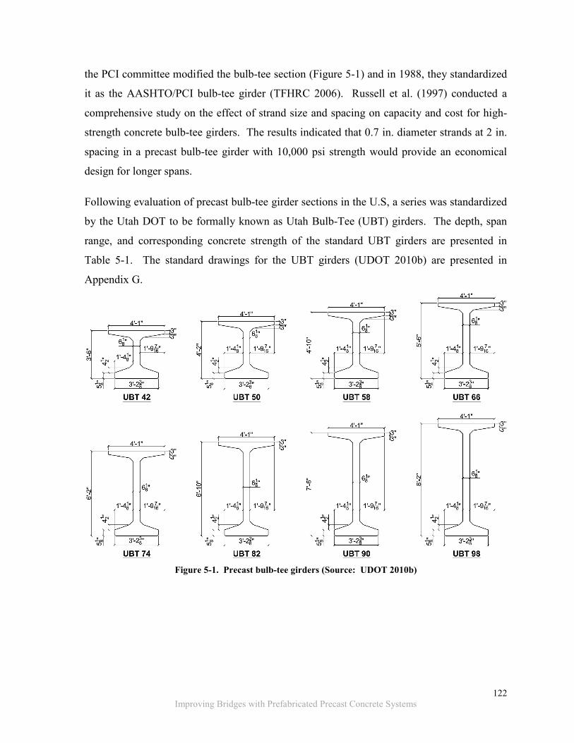
the PCI committee modified the bulb-tee section (Figure 5-1) and in 1988, they standardized
it as the AASHTO/PCI bulb-tee girder (TFHRC 2006). Russell et al. (1997) conducted a
comprehensive study on the effect of strand size and spacing on capacity and cost for high-
strength concrete bulb-tee girders. The results indicated that 0.7 in. diameter strands at 2 in.
spacing in a precast bulb-tee girder with 10,000 psi strength would provide an economical
design for longer spans.
Following evaluation of precast bulb-tee girder sections in the U.S, a series was standardized
by the Utah DOT to be formally known as Utah Bulb-Tee (UBT) girders. The depth, span
range, and corresponding concrete strength of the standard UBT girders are presented in
Table 5-1. The standard drawings for the UBT girders (UDOT 2010b) are presented in
Appendix G.
Figure 5-1. Precast bulb-tee girders (Source: UDOT 2010b)

123
Improving Bridges with Prefabricated Precast Concrete Systems
Table 5-1. Depth and Span Range of Utah Bulb-Tee Girders (Source: UDOT 2010b)
Depth (in.)
Span (ft)
Diameter of prestressing
strands (in.)
Number of
strands 28-day concrete strength of 6,500 psi
28-day concrete strength of 8,500 psi
Utah bulb-tee girders
spaced at 8 ft
42 ~85 ~98
0.6 Varies
50 ~97 ~117 58 ~112 ~131 66 ~124 ~146 74 ~140 ~157 82 ~150 ~167 90 ~164 ~177 98 ~169 ~186
Sources of information: Mills et al. (1991); Seguirant (1998); Lavallee and Cadman
(2001); Castrodale and White (2004); Fouad et al. (2006); Browder (2007); UDOT (2010b).
Constructability evaluation: The precast bulb-tee girders are appropriate for developing
continuous spans. Special details and CIP construction are required to develop continuity
over the piers. (See Section 5.2.1.4 – Continuity Detail over the Pier or a Bent for Details.)
ABC implementation can be accomplished with partial-depth or full-depth deck panels. As
indicated earlier, the use of partial-depth deck panels is not recommended due to reflective
deck cracking potential. When used with full-depth deck panels, the controlling girder sweep
is critical due to slenderness of the section. The use of a wide bottom flange in the precast
bulb-tee girders results in a stable section and accommodates a larger number of prestressing
strands.
For bridges with restrictions for pier placement, spliced spans extending up to medium spans
could be achieved with multiple precast bulb-tee girders. Post-tensioning can be used for the
full length of the bridge when spliced spans are utilized. However, the web width needs to
be increased in spliced girders to accommodate the post-tensioning ducts (Figure 5-2).
Splicing options and details are discussed in the NCHRP report 517 (Castrodale and White
2004).
The splicing operation requires more time that will extend the construction schedule.
Further, a CIP concrete diaphragm is typically required at the spliced location. As was
mentioned earlier, with post-tensioning, the repair or rehabilitation activity options will be

124
Improving Bridges with Prefabricated Precast Concrete Systems
limited. Before repair, rehabilitation or demolition operations, the stability of the system
needs to be evaluated.
Figure 5-2. Precast bulb-tee with post-tensioning in the web (Source: Castrodale and White 2004)
5.1.2 Full-Depth Deck Panels
DOTs are sometimes reluctant to use post-tensioning (FHWA 2012). However, a full-depth
deck panel system with transverse prestressing and longitudinal post-tensioning is
recommended. This recommendation is supported by the deck’s superior durability
performance. Transverse prestressing provides crack control and allows using thinner deck
panels and wider spacing of supporting girders. Longitudinal post-tensioning can be
designed so that the deck remains under compression under all service load conditions,
resulting in a durable system. Moreover, full-depth deck panels have been implemented in
several ABC projects, from which lessons-learned reports are available. Additionally,
designers and precast plants have experience with the system.
5.1.2.1 Full-Depth Deck Panels with Transverse Prestressing and Longitudinal Post-tensioning
Description: Full-depth deck panels have been used since the early 1970’s (Issa et al.
1995a). The full-depth deck panels can be used in the deck replacement, superstructure
replacement and bridge replacement projects. The transverse prestressing allows casting
deck panels as wide as 40 ft [i.e., dimension in transverse direction of the bridge (Figure 5-3
a)].

125
Improving Bridges with Prefabricated Precast Concrete Systems
The UDOT (2010b) developed standard details for the full-depth deck panels. (See Appendix
F for details.) The UDOT (2010b) allows the use of skewed panels up to 15o (Figure 5-3 b).
For skew decks up to 45o, rectangular interior panels with trapezoidal end panels are
specified (Figure 5-3 c).
(a) Non-skewed bridge
(b) Bridge with skew between 00 and 150
(c) Bridge with skew greater than 150
Figure 5-3. Standard full-depth deck panel applications (Source: UDOT 2010b)

126
Improving Bridges with Prefabricated Precast Concrete Systems
Full-depth deck panel length (in the direction of traffic) with transverse prestressing could
vary from 8 ft to 16 ft. The panel width (in the direction transverse to traffic) could vary from
24 ft to 40 ft. Several projects specified a deck thickness of 8.5 in. with concrete strength of
4,000 psi at release and 5,000 psi at 28 days. The supporting girder spacing for the deck
panels with transverse prestressing could vary from 8 ft to 12 ft. Steel girders with a
minimum top flange width of 16 in., AASHTO types II to VI girders, or precast bulb-tee
girders are commonly used.
Sources of information: Hieber et al. (2005); Badie et al. (2006); Higgins (2010); UDOT
(2010b); Attanayake et al. (2012).
Constructability evaluation: The uncertainty related to the full-depth deck panel’s
durability performance is the tightness of transverse connections. The connection details
promising best performance are discussed in Section 5.2.1.1 – Transverse Connection at the
Deck Level.
Staged construction with full-depth deck panels is possible (Figure 5-4). During staged
construction, vibrations generated by the traffic may promote cracking within the cement
matrix and at the interface of the longitudinal closure. Reinforcement overlapping conflicts
at the closure are documented in post-construction reports. This can be addressed by
educating the detailers of the issue, while specifying and enforcing the best practices for
tolerances.
AASHTO (2010) specifies 250 psi compression at the panel transverse connection after all
the prestressing losses. The continuous span structures should be analyzed in the vicinity of
the piers to determine the level of post-tensioning required to achieve nominal 250 psi
compression at connections. Transverse connections should be placed away from the pier
locations to minimize the potential for developing tensile stresses. The maximum post-
tension duct spacing should be less than panel length (Ulku et al. 2011). Tolerances at the
post-tension duct splicing locations should be appropriate to minimize misalignment. To
reduce the difficulties associated with the strand placement in the post-tensioning ducts,
round ducts are preferred over the flat ducts (Badie et al. 2006). Moreover, to prevent
excessive friction during post-tensioning operation, adequate space should be maintained

127
Improving Bridges with Prefabricated Precast Concrete Systems
between the strands and the ducts. For example, if 4-0.6 in. diameter strands are allowed for
a particular duct, the design may be based on 4-0.5 in. diameter strands.
The deck system contains several grouted connections thus making the construction
challenging. Therefore, special provisions need to direct the contractor to identify the
grouting procedures and to demonstrate the effectiveness of the procedures by performing
mock-up testing. The difficulties with grout selection and application are discussed in
Section 2.4. The panels should be properly supported until the haunch grout achieves the
required strength. For supporting the deck panels, in each deck panel, at least two (2)
leveling devices per girder need to be provided. Proper tolerances at the shear pockets
should be specified and verified. The shear pockets and leveling device details are discussed
in Section 5.2.1.3 – Deck-to-Girder Connection–Blockouts.
The following challenges are encountered when implementing full-depth deck panel systems:
• Specifying and enforcing the required tolerances during the fabrication process,
• Enforcing the construction tolerances during the assembly process,
• Transporting the trapezoidal end panels used in the high skew bridges, and
• Replacing a single girder or a panel in a system with post-tensioning.
Figure 5-4. Stage construction configuration for full-depth deck panels (Source: UDOT 2010b)

128
Improving Bridges with Prefabricated Precast Concrete Systems
5.1.3 Modular Superstructure Elements
The two modular superstructure elements recommended for potential implementation are
described below.
1. Decked bulb-tee girder: This section has been implemented in several projects in
Florida, New York, Utah, and a few states in the New England region. UDOT
(2010b) standardized this section for spans up to 180 ft. The superstructure can be
formed by placing the units next to each other and providing a connection for moment
and shear transfer. The superstructure can be designed with or without an overlay.
Overlay is recommended for durability. The precast forms for the precast bulb-tee
girders could also be utilized to cast the decked bulb-tee girder elements.
2. Decked box-beam: This section is recommended based on recent positive
experiences in Michigan. The superstructure can be used with or without an overlay.
Again, overlay is recommended for durability. The precast forms for casting the
adjacent box-beams could be utilized to cast the decked box-beam elements. Precast
plants and contractors often have experience with the precast box-beams; thus,
prefabrication of the decked configuration will not be challenging.
5.1.3.1 Decked Bulb-Tee Girder
Description: The decked bulb-tee girder (Figure 5-5) was developed in 1969 by Arthur
Anderson based on the standard tee girder. The standard tee girder was commonly specified
for parking structures and the building industry in early 19th century. The New England
states, Utah, and Florida have specified the decked bulb-tee girder section in several projects.
The New York State DOT has implemented this section in a few projects since 2009.
The decked bulb-tee girders can be manufactured in a single pour, which makes the
fabrication easier compared to a single cell box-beam. The decked bulb-tee girders provide
the flexibility for accommodating utility lines. When compared to the double-tee girder
elements, decked bulb-tee girders can be designed for a greater load carrying capacity for
equal span lengths. A wearing surface, or an overlay, is required once the decked bulb-tee
girders are assembled on the site (Figure 5-6).

129
Improving Bridges with Prefabricated Precast Concrete Systems
UDOT (2010b) standardized the decked bulb-tee girder with flange widths ranging from 4 ft
to 8 ft, depths ranging from 35 in. to 98 in., and spans of up to 180 ft. The maximum span
has not been implemented in ABC projects primarily due to limitations in transporting the
sections to the bridge site. The standard drawings for the decked bulb-tee girder by UDOT
(2010b) are presented in Appendix G.
Sources of information: PCI (2011); Shah et al. (2006); UDOT (2010b); Culmo (2011).
Constructability evaluation: As with any modular system, the connections between the
decked bulb-tee girders can fail unless designed as a flexure-shear transfer connection.
Standard details for deck level longitudinal connection are developed and presented in
Section 5.2.1.2 – Longitudinal Connection at the Deck Level.
UDOT (2010b) specifies a span up to 180 ft. As with any other bridge system, use of deep
girders for medium span bridges is not practical in most sites due to underclearance issues.
Some considerations related to the use of decked bulb-tee girders are as follows:
• The spacing of the diaphragms between the decked bulb-tee girders needs to be
researched to achieve the desired level of torsional stiffness.
• The weight of the decked bulb-tee girders needs to be considered during the design
process, to comply with transportation limitations, and
• The crown of the riding surface on the decked bulb-tee girders can be formed by an
overlay. There is preference for use of latex modified concrete or epoxy overlay over
an asphalt overlay with a waterproofing membrane.

130
Improving Bridges with Prefabricated Precast Concrete Systems
Figure 5-5. Typical section of a decked bulb-tee girder (Source: PCI 2011)
Figure 5-6. Decked bulb-tee girder (Source: CPMP 2011)
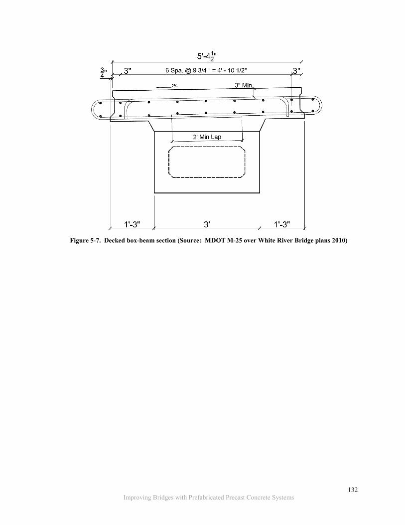
5.1.3.2 Decked Box-beam
Description: The decked box-beam element is the traditional box-beam with a built-in deck
(Figure 5-7). This element was developed by Michigan DOT to provide a prefabricated
element, which inherits the benefits of an adjacent box-beam, and when assembled on site,
resembles a spread box-beam bridge. The decked box-beam system was implemented for
ABC in 2011 to replace M-25 over the White River Bridge (B01 of 32091) in Michigan.

131
Improving Bridges with Prefabricated Precast Concrete Systems
Transverse post-tensioning similar to side-by-side box-beam bridges, through the CIP
diaphragms, was specified. The beam depth was 3 ft (including the deck) and spanned 47 ft.
The top flange width of the beams was 5 ft-5 in. The specified 28-day compressive strength
was 7000 psi.
The decked box-beam section is suitable at sites with underclearance limitations. As the
decked box-beam resembles the spread box-beam bridge, utilities could be accommodated.
The weight of the decked box-beam may be the factor limiting the use for short-span bridges
(20 ft to 60 ft).
Source of information: MDOT M-25 over White River Bridge plans (2010); MDOT-BDM
(2011).
Constructability evaluation: The decked box-beam section is new, and past performance
data is limited. The longitudinal deck connection detail used with these beams needs to be
designed to transfer both moment and shear. Standard deck level longitudinal connection
details are developed and presented in Section 5.2.1.2 – Longitudinal Connection at the Deck
Level. The designers should be aware of shipping and handling weight limitations while
designing these sections for increased spans.
The typical sequence of precasting the decked box-beam is to fabricate the box-beam, place
the deck reinforcement on top of the box-beam, and cast the deck. The deck reinforcement
placement and the deck casting operation scheduling is critical to prevent a cold joint
between the deck and the box-beam.
Some of the considerations related to the use of decked box-beams are these:
• Difficulty of inspection of the box-beam interior,
• Difficulty in the fabrication, because of the multi-step process, and
• Difficulty in replacing single or multiple units because of the transverse post-
tensioning.
132
Improving Bridges with Prefabricated Precast Concrete Systems
Figure 5-7. Decked box-beam section (Source: MDOT M-25 over White River Bridge plans 2010)
133
Improving Bridges with Prefabricated Precast Concrete Systems
5.1.4 Modular Superstructure Elements with an Implementation Potential
Modular superstructure elements, which have a potential for implementation, but require
additional investigation for successful use in ABC projects are presented below:
1. Precast adjacent box-beams: This is the classic system specified to accelerate the
construction with several inherent advantages. Many state DOTs, prefabricators, and
contractors are familiar with the system. Because of large inventory, the past
performance data is available going back to the 1950s. The major obstacle is the
reflective deck cracking which leads to premature deterioration. Even with the
reflective deck cracking potential, the system is widely specified because of a lack of
alternatives for sites with underclearance limitations.
2. Inverted-T precast slab: This element is recommended because of its high span-to-
depth ratio, which is suitable for implementation with underclearance limitations.
Further, this element eliminates the formwork requirement for the CIP deck. Again,
there is potential for reflective cracking along the longitudinal connection. A recent
NCHRP-10-71 project proposed a few design changes for improving the connection.
The new details have not been tested for performance to determine its durability.
3. Northeast Extreme Tee (NEXT) D beam element: This element is selected because
of its higher load carrying capacity than standard double tee girders. These elements
are suitable for bridges with up to a 90 ft span and with underclearance limitations.
Additional studies are needed on the section in order to clarify the following: i)
ambiguous live load distribution, ii) sufficiency of the longitudinal connection detail,
and iii) optimality of the cross-section.
5.1.4.1 Precast Adjacent Box-beams
Description: These elements have been in use in Michigan since 1955 (Attanayake 2006).
There is extensive experience with their design and performance. These elements are ideal
for sites with underclearance limitations. The construction can be accelerated by specifying a
wearing surface without a cast-in-pace deck directly over the box girders (Figure 5-8). These
elements possess high torsional stiffness and can be used for constructing aesthetically
pleasing shallow-depth structures.

134
Improving Bridges with Prefabricated Precast Concrete Systems
Sources of information: Aktan et al. (2009); Attanayake (2006); Stamnas and Whittemore
(2005); Chung et al. (2008); MDOT-BDM (2011); Ulku et al. (2010).
Constructability evaluation: Field inspection has documented grout spall and inadequate
gaps between beams for forming the shear keys (Aktan et al. 2009). Tighter fabrication
tolerances need to be specified. Reflective cracking is common among the inventory
constructed with a CIP deck. Therefore, a redesign of the transverse connectivity of the
adjacent box-beams will mitigate the reflective cracking (Ulku et al. 2010). Box-beam
attributes are shown in Table 5-2.
Table 5-2. Attributes of Precast Adjacent Box-beams Used in Michigan (Source: MDOT-BDM 2013)
Depth range
(in.) Spans up to
(ft) 28 day concrete strength
(psi) Box-beam
(36 in. wide) 17 – 42 ~120 5,000 – 7,000
Box-beam (48 in. wide) 21 – 60 ~150 5,000 – 7,000
Some of the considerations related to the use of these elements are as follows:
• Fabrication complexity due to the multi-step fabrication process of the box,
• Inspection difficulties of the box-beam interior,
• Difficulty in accommodating utilities underneath the superstructure, and
• Difficulty in replacing an individual beam due to transverse post-tensioning.

135
Improving Bridges with Prefabricated Precast Concrete Systems
Figure 5-8. Adjacent box-beams that require a wearing surface (Source: CPCI 2006)
5.1.4.2 Inverted-T Precast Slab
Description: The inverted-T precast slab elements are assembled adjacent to each other so
that formwork is not required for casting the connections and the deck. The transverse
reinforcement protruding from the precast elements provides the moment continuity across
the connection (Figure 5-9). These elements have been used by the Minnesota DOT in
several projects since 2005.
These elements are suitable for spans up to 65 ft (i.e., short span bridges). The typical width
is 6 ft, and the depth is 30 in. (for elements of 65 ft span). The depth includes the 24 in. deep
precast section and 6 in. thick CIP deck. Because of their shallow depth, these elements are
ideal for sites with underclearance limitations. Concrete with a 28-day strength of 6,500 psi
is commonly specified for these elements, and a 28-day strength of 4,000 psi is specified for
the CIP deck.
Sources of information: Bell II et al. (2006); French et al. (2011).
Constructability evaluation: These elements require a reinforcement cage along the
longitudinal joint with the CIP deck. The transverse reinforcement (Figure 5-9 and Figure
5-10) allows anchoring the preassembled reinforcement cage (Figure 5-11). The CIP deck

136
Improving Bridges with Prefabricated Precast Concrete Systems
increases the project duration. The implementation of these elements in Minnesota has been
limited to the short span bridges (20 ft to 60 ft).
The observed reflective cracking at the longitudinal joints was described as a durability
concern. A recent NCHRP-10-71 project (French et al. 2011) investigated the performance
of these elements. Moreover, the investigations revealed that the elements with depth greater
than 22 in. require large amounts of confining reinforcement in the end regions. The time-
dependent restraint moments in the full bridge system were identified to dominate the creep
of individual elements. The NCHRP-10-71 project proposed design changes to account for
the reflective cracking and bursting stresses at the end regions. The new but untested details
for the inverted-T precast slab section are shown in Figure 5-10 and Figure 5-11 b.
(a) End section
(b) Midspan section
Figure 5-9. Old detail of the inverted-T precast slab

137
Improving Bridges with Prefabricated Precast Concrete Systems
(a) End section
(b) Midspan section
(c) Standardized reinforcing bars
Figure 5-10. New detail proposed by the NCHRP for the inverted-T precast slab

138
Improving Bridges with Prefabricated Precast Concrete Systems
(a) Old detail
(b) New detail proposed by the NCHRP
Figure 5-11. Reinforcement cage at longitudinal joint of the inverted-T precast slab
5.1.4.3 Northeast Extreme Tee (NEXT) D Beam
Description: The NEXT D beam is a modified version of the standard double tee girder.
The NEXT D beam does not require a CIP deck and has a wider stem that can accommodate
large number of prestressing strands (Figure 5-12). These elements have been designed for
greater load carrying capacity than the standard double tee girders. This section is approved
for use in Connecticut, Massachusetts, Maine, New Hampshire, Rhode Island, Vermont,
Delaware, Maryland, and New Jersey.
The Precast Prestressed Concrete Institute Northeast chapter (PCI NE) has developed
standard details for the NEXT D beam elements. (See Appendix H for details.) The NEXT D
beam elements can be cast in a single pour. Also, standardized depth, spacing, and size of
stems allow different element widths, ranging from 8 ft to 12 ft, to be produced with one set
of formwork (Figure 5-12). The spans range from 40 ft to 90 ft, and the depth ranges from
24 in. to 36 in. at 4 in. increments. The NEXT D beam of 90 ft length weighs about 160 kips.
Sources of information: Calvert (2010); Culmo and Seraderian (2010); PCI NE (2011);
Culmo (2011).

139
Improving Bridges with Prefabricated Precast Concrete Systems
Constructability evaluation: The NEXT D beam elements are designed without
intermediate diaphragms. The lack of the intermediate diaphragms may lead to undefined
load distribution and excessive twist under live load.
The NEXT D beam elements and their connection details are new, and past performance data
is limited. Durability performance of longitudinal connections between the elements needs
to be evaluated. The potential connection details for such systems are discussed in Section
5.2.1.2 – Longitudinal Connection at the Deck Level.
The NEXT D beam consists of wide stems. This cross section is non-optimal which results
in excess weight. Therefore, the use of these elements in bridge construction will be limited.
Figure 5-12. NEXT D beam element (Source: PCI NE 2011)

140
Improving Bridges with Prefabricated Precast Concrete Systems
5.1.5 Modular Superstructure Systems
The modular superstructure systems presented in Appendix A include the INVERSETTM
(proprietary) and the decked steel girder (non-proprietary). The recommended modular
superstructure system for immediate implementation is described below
1. The decked steel girder system: This system is recommended because it is non-
proprietary and fabrication is simple. The system is more suitable for bridges in non-
corrosive environments. This system requires a wearing surface to enhance durability
once assembled on-site.
5.1.5.1 Decked Steel Girder System (Also Referred as Decked Steel Girder Module)
Description: The decked steel girder system was developed in a SHRP II project; it was
implemented in the I-93 Fast 14 project in Medford, MA (MassDOT 2011) and the Keg
Creek Bridge replacement project in Pottawattamie County, IA (IowaDOT 2011).
The modules consist of two W 30x99 (depth: 29.7 in.), ASTM A709 grade 50W steel
girders, integral with a 7.5 in. to 8 in. deep precast deck (Figure 5-13). The section width
ranges from 8 ft to 9 ft with a 28-day compressive strength of 4000 psi to 5000 psi. Up to 73
ft spans have been implemented with the section details shown in Figure 5-13.
Sources of information: Shutt (2009); LaViolette (2010); MassDOT (2011); IowaDOT
(2011); Moyer (2011).
Constructability evaluation: Manufacture of this module requires steel fabricators and
precasters to work together. The crown of the decked steel girder bridge could be formed in
two ways: i) increasing the thickness of the deck, and diamond grinding part of the deck to
the desired crown, and ii) placing an overlay over the deck to form the crown.
Use of weathering steel can help with corrosion prevention. However, the system, even with
weathering steel, is not suitable for Michigan exposure with aggressive winter maintenance.
The past performance data of the decked steel girder system is limited. The success of the
decked steel girder system is controlled by the performance of the longitudinal connections.
The recommended longitudinal deck connection details and continuity details over the piers

141
Improving Bridges with Prefabricated Precast Concrete Systems
and abutments are discussed in Section 5.2.1.2 – Longitudinal Connection at the Deck Level
and Section 5.2.1.4 – Continuity Detail over the Pier or a Bent.
(a) Section elevation
(b) Section details
Figure 5-13. Decked steel girder system (Source: MassDOT 2011; IowaDOT 2011)

142
Improving Bridges with Prefabricated Precast Concrete Systems
5.1.6 Substructure Elements and Reduced-Weight Options
Since the inception of ABC, several substructure elements and connection details have been
developed. The substructure elements that were identified during the literature review are
presented in Appendix A.
Transport and placement impose limits to the weight of prefabricated components. For
example, the MDOT-BDM (2013) Section 7.01.19 recommends limiting weights of PBES to
80 kips (40 tons) for safe handling using conventional equipment. Due to similar constraints,
the ABC Toolkit developed under the SHRP2 R04 project (SHRP2 2012) recommends
limiting weights to 160 kips (80 tons). Where site conditions allow, SHRP2 (2012) suggests
using PBES up to 250 kips (125 tons) to build longer spans or wider bridges to minimize
construction duration.
Generally, the substructure is considered bulky and heavier compared to the girders.
According to Table 2-1, a span length greater than 50 ft with decked bulb-tee and decked
box-beam sections with 9.5 in. thick flange cannot be attained when the PBES weight is
limited to 40 ton (80 kips). In other words, bridge span and girder type also need to be
considered when defining weight limits for substructure components. Options are available
for reducing substructure element weight. Generally, the section weight can be reduced by
removing the material that does not contribute to section capacity or the stiffness, applying
prestressing or post-tensioning, or a combination thereof.
The substructure elements that show potential for immediate implementation are as follows:
1. Precast abutment walls and stems: Use of precast abutment walls and stems are
recommended. Some of the recommended stem sections are cast with cavities to
reduce weight. Additionally, segmental stems are recommended for sites with limited
access for large equipment.
2. Precast column: Octagonal and square/rectangular columns are recommended.
These precast columns are preferred because they do not require vertical casting and
are easy to secure during transportation. Segmental columns with precast hollow
sections are recommended for sites with limited access for large construction
equipment.

143
Improving Bridges with Prefabricated Precast Concrete Systems
3. Precast pier/bent cap: The recommended bent caps include the rectangular and the
trapezoidal shapes. These bent caps are preferred because they reduce the number of
required substructure elements (i.e., columns and footings). In addition, a bent cast
with cavities, tapered sections, or a combination thereof is recommended for reduced
weight.
5.1.6.1 Precast Abutment Walls and Stems
Description: The precast abutment walls and stems were used in several ABC projects in
the U.S. Use of walls or stems depends on the site condition. An example project with an
abutment wall is the M-25 over the White River Bridge in Michigan (Figure 5-14). The
precast abutment walls are used with spread footing while the stems are used with piles. The
abutment wall on spread footing is also known as a cantilever abutment.
Figure 5-14. Abutment wall on spread footing (Source: MDOT M-25 over White River Bridge Plans)
For sites requiring a spread footing, the precast abutment wall is usually cast in segments to
help with shipping and handling of the component. For sites requiring piles, the precast
abutment stem is cast either in segments or as a single element based on site constraints.
Another option of reducing abutment stem weight is to use redundant pile cavities to be filled
in the field (Figure 5-15).

144
Improving Bridges with Prefabricated Precast Concrete Systems
Figure 5-15. Segmental abutment with redundant pile cavities (Source: Culmo 2009)
The abutments can be designed as integral or semi-integral. The semi-integral abutment is
recommended because of the following: (1) placing the prefabricated superstructure is
simpler on the constructed abutment, (2) the semi-integral abutment provides access for
inspection and maintenance of the bearing, (3) future superstructure repair and replacement
activities can be accommodated, and (4) the semi-integral abutment simplifies substructure
design especially in high-skew bridges.
The height of a precast abutment wall varies from 4ft to 10ft, and its thickness is around 2 ft.
Precast abutment stem height and thickness vary between from 3 ft and 4 ft, and the length
can be up to 14 ft. The typical 28-day compressive strength used in precast substructure
elements varies from 4,000 psi to 5,000 psi.
Sources of information: Stamnas and Whittemore (2005); MDOT M-25 over White River
Bridge plans (2010); Culmo (2009); UDOT (2010b).
Constructability evaluation: For sites requiring spread footings, the abutment walls are
placed into the channel cast in the spread footing. Connectivity is achieved through grouted
splice-sleeve connection. Tight tolerances are required for the proper fit of the precast
elements while using grouted splice sleeve connections. Refer to Section 5.2.2.3 – Abutment
Wall to Footing Connection for design details and potential strategies for improved
constructability.

145
Improving Bridges with Prefabricated Precast Concrete Systems
In sites requiring piles, tighter tolerances are required for the pile driving operation when a
precast abutment stem is used. A steel template is commonly used to assure accuracy of pile
placement (Figure 5-16). The abutment stems are connected to the piles using various types
of grouted connections. (See Section 5.2.2.1 – Pile Cap or Abutment Stem to Pile Connection
for details.) During the abutment stem placement over the piles, for leveling, a gap needs to
be maintained between the end of the pile and the precast abutment stem. With this gap,
maintaining a proper grade with the abutment stem is difficult. To maintain the grade, a CIP
concrete slab on grade can be placed as shown in Figure 5-17.
Post-tensioning is commonly specified for abutment stems casted in segments. Other vertical
connection details without post-tensioning are discussed in Section 5.2.2.5 – Vertical
Connection between Elements. Grouting of the vertical shear keys between the abutment
segments (i.e., splices) (Figure 5-14) needs further study. Projects have reported joint
forming and sealing difficulties under significant pressure head due to the height of the
abutment stem.
Moreover, when the redundant pile cavities (Figure 5-15) are used in an abutment stem to
reduce the weight, the formwork to form the cavity may create difficulties during the casting
process. Grouting large cavities will be difficult because of fill depth limits of most grouts.
The use of concrete and special concrete mixes for filling cavities in substructure elements
needs to be investigated.
Figure 5-16. Template used for maintaining pile driving tolerances (Source: Photo courtesy of MDOT)

146
Improving Bridges with Prefabricated Precast Concrete Systems
Figure 5-17. Concrete slab on ground to maintain the proper grade for placing the abutment stem
(Source: Photo courtesy of MDOT)
5.1.6.2 Precast Columns
Description: Precast columns of circular, I-shape, octagonal, square/rectangular, and oval-
shape have been implemented in various projects. The oval-shape is typically used for the
piers of long and wide bridges. The I-shape is typically used for the piers of tall structures
where increased lateral stiffness is required. For the short and short-to-medium span bridges,
the circular, square/rectangular, and octagonal shapes are used.
According to the precast industry, a circular cross-section can only be cast in vertical position
which creates difficulties. For that reason, New England states, Florida, Texas, and Utah
prefer using octagonal precast columns. Other states such as Iowa, Washington, and
California use square/rectangular precast columns. If needed, there are various ways of
casting circular sections in horizontal position as accomplished by the concrete pole
industry’s centrifuge casting.
The octagonal columns (Figure 5-18) and square/rectangular columns (Figure 5-19) are easy
to fabricate and are more stable during the shipping and handling process.

147
Improving Bridges with Prefabricated Precast Concrete Systems
Figure 5-18. Octagonal column (Source: UDOT 2010b)
Figure 5-19. Square/Rectangular column (Source: IowaDOT 2011)
Sources of information: Shahawy (2003); UDOT (2010b); Khaleghi (2011).
Constructability evaluation: The octagonal and rectangular precast columns can be
fabricated in horizontal position, thus providing flexibility by using long forms to provide the
ability to cast multiple columns at once. Higher strength concrete can be specified, and
prestressing can be used to achieve taller and more durable precast columns.

148
Improving Bridges with Prefabricated Precast Concrete Systems
Specified tolerances need to be stricter for column connections to footings and to bent caps.
Refer to Section 5.2.2.2 – Column to Footing Connection and Section 5.2.2.4 – Pier Cap or
Bent Cap to Pier or Column Connection for design details and potential strategies to mitigate
constructability issues.
Transporting columns may create difficulties depending on the height and weight. A
rectangular precast column with a similar load carrying capacity to an octagonal column has
a greater weight.
5.1.6.3 Precast Pier/Bent Cap
Description: The precast pier/bent caps are common prefabricated substructure elements
that distribute the load from the bridge superstructure uniformly to the foundation. The
commonly specified bent cap geometries are: i) rectangular (Figure 5-20) and ii) trapezoidal
(Figure 5-21). The bent caps are useful for the bridge sites crossing power/utility lines,
waterways, and highway-rail grade crossings. The use of bent caps minimizes the required
number of columns and footings.
Usually, one bent cap is used to support the full-width of the superstructure, whereas multiple
trapezoidal bent caps are used for the full-width (Figure 5-21). The typical height of a bent
cap is 3 ft to 4.5 ft, and the width is 3 ft to 4 ft.
The UDOT (2010b) standardized the bent caps as: i) single column hammer head bent
(Figure 5-22 a), ii) two column bent (Figure 5-22 b), and iii) three column bent (Figure 5-22
c). Any combination of any of two or three column bent caps is used to support the full-
width of a superstructure (UDOT 2010b).

149
Improving Bridges with Prefabricated Precast Concrete Systems
Figure 5-20. Rectangular bent cap (Source: http://facilities.georgetown.org/2009)
Figure 5-21. Trapezoidal bent cap (Source: Restrepo et al. 2011)
(a) Single column hammer head bent
(b) Two column bent
(c) Three column bent
Figure 5-22. UDOT standardized bent cap sections (Source: UDOT 2010b)

150
Improving Bridges with Prefabricated Precast Concrete Systems
Sources of information: LoBuono (1996); Billington et al. (1999); Matsumoto et al. (2001);
Ralls et al. (2004); UDOT (2010b); Restrepo et al. (2011).
Constructability evaluation: The bent cap weight needs to be considered for transport and
handling.
Depending on the type of connection for the bent cap to column or pier cap to pier, the
specified tolerances needs to be stricter. Refer to Section 5.2.2.4 – Pier Cap or Bent Cap to
Pier or Column Connection for design details and potential strategies to mitigate construction
challenges.
Prestressing may be used to reduce the height and weight of the element. A precast inverted-
T bent cap was proposed by Billington et al. (1999), which can be prestressed (Figure 5-23 a,
b) to achieve shallow depth and extended length of up to 42.5 ft. Also, the section geometry
can be optimized to reduce the weight of the bent cap (i.e., reducing the section around the
center of the cap and bottom corners of the flange, Figure 5-23 c, d). The recommended
design with web walls of 14 in. thickness provides sufficient cover, anchorage zone, and
shear reinforcement in the bent cap. Implementation of the inverted-T bent cap could not be
identified. Further study is required to establish the applicability of the details proposed by
Billington et al. (1999).
Another approach to reduce the weight of the bent cap element is to eliminate a section using
embedded corrugated metal casing. Refer to Section 5.2.2.1 – Pile Cap or Abutment Stem to
Pile Connection for design details. The approach needs further analysis before being
considered for implementation.

151
Improving Bridges with Prefabricated Precast Concrete Systems
(a) Plan view
(b) Elevation view
(c) Section through the cantilever portion
(d) Isometric view showing the voids
Figure 5-23. Inverted-T prestressed bent cap (Source: Billington et al. 1999)
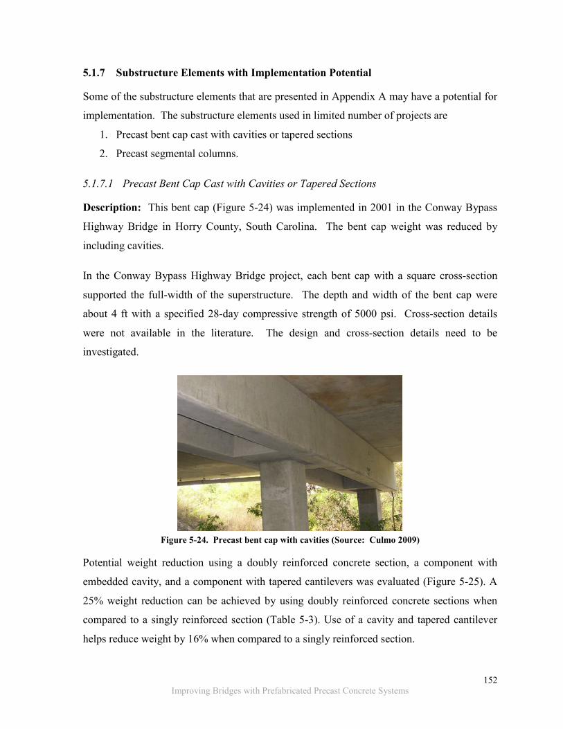
152
Improving Bridges with Prefabricated Precast Concrete Systems
5.1.7 Substructure Elements with Implementation Potential
Some of the substructure elements that are presented in Appendix A may have a potential for
implementation. The substructure elements used in limited number of projects are
1. Precast bent cap cast with cavities or tapered sections
2. Precast segmental columns.
5.1.7.1 Precast Bent Cap Cast with Cavities or Tapered Sections
Description: This bent cap (Figure 5-24) was implemented in 2001 in the Conway Bypass
Highway Bridge in Horry County, South Carolina. The bent cap weight was reduced by
including cavities.
In the Conway Bypass Highway Bridge project, each bent cap with a square cross-section
supported the full-width of the superstructure. The depth and width of the bent cap were
about 4 ft with a specified 28-day compressive strength of 5000 psi. Cross-section details
were not available in the literature. The design and cross-section details need to be
investigated.
Figure 5-24. Precast bent cap with cavities (Source: Culmo 2009)
Potential weight reduction using a doubly reinforced concrete section, a component with
embedded cavity, and a component with tapered cantilevers was evaluated (Figure 5-25). A
25% weight reduction can be achieved by using doubly reinforced concrete sections when
compared to a singly reinforced section (Table 5-3). Use of a cavity and tapered cantilever
helps reduce weight by 16% when compared to a singly reinforced section.

153
Improving Bridges with Prefabricated Precast Concrete Systems
(a) Rectangular section (b) Rectangular section with a cavity
(c) Section with tapered cantilever sections
Figure 5-25. Bent cap configurations
Table 5-3. Comparison of Bent Cap Weight Reduction
Bent Configuration Volume (ft3) Weight (kips) Wt. Reduction (%)
Standard rectangular (singly reinforced design) 378.0 56.7 -
Rectangular (doubly reinforced design) 283.5 42.5 25.0
w/ Cavity 317.5 47.6 16.0
w/ Tapered cantilever 318.5 47.8 15.7
Sources of information: Shahawy (2003); Culmo (2009).
Constructability evaluation: Fabrication and reinforcement detailing of the bent cap with
cavities may create difficulties. Potential connection details of the bent cap to the column are

154
Improving Bridges with Prefabricated Precast Concrete Systems
discussed in Section 5.2.2.4 – Pier Cap or Bent Cap to Pier or Column Connection.
Prestressing can be an option to further reduce the cross-section dimensions.
5.1.7.2 Precast Segmental Columns
Description: A hollow precast segmental column was designed by Billington et al. (2001)
under the sponsorship of FHWA and Texas DOT. The columns consist of multiple precast
segments and a template (capital) (Figure 5-26 a). The desired column height could be
achieved by increasing/ decreasing the number of segments and segment heights. The weight
of each segment can be limited to allow ease in transporting and placing. The precast
template (Figure 5-26 a) helps with aligning the pier with the bent cap or girder elevation.
The hollow section of the segment (Figure 5-26b) can accommodate drainage ducts. Girders
can be directly placed on the segmental columns to eliminate the bent cap (Figure 5-27).
The precast segmental column was implemented in a short-span bridge project in Texas (U.S.
Highway 249 over Louetta Road in Houston). No other implementation was documented in
the literature. Because of limited application and lack of performance data, further review is
recommended before specifying these substructure elements.
(a) Elevation
(b) Section
Figure 5-26. Precast segmental column (Source: Billington et al. 2001; Shahawy 2003)

155
Improving Bridges with Prefabricated Precast Concrete Systems
Figure 5-27. Short-span bridge with precast segmental columns (Source: Shahawy 2003)
The precast segmental column characteristics are as follows:
• Length of each segment 3 ft to 6 ft,
• Depth of cross-section 4 ft to 10 ft,
• Width of cross-section is 4 ft, and
• Specified 28-day compressive strength is 5000 psi.
Sources of information: Billington et al. (2001); Shahawy (2003); PCI (2011).
Constructability evaluation: The precast template (capital) is aligned with the bent cap or
girder elevation with adjustable supports on the top segment of the precast segmental
column. High-strength epoxy grout is specified for the joint between the precast template
and the top segment of column. The match-cast joints between the segments allow for an
accelerated construction process. However, for using match-cast joints, each segment must
be labeled for identification. There are two possible connection details for the precast column
segments: i) grouted splice coupler connection and ii) vertical post-tensioning. (See Section
5.2.2.6 – Connection between Segmental Columns or Piers for details.)
To minimize the segment weight, a suitable section type and size needs to be developed for
short and short-to-medium span bridges. This requires further review before implementation.

156
Improving Bridges with Prefabricated Precast Concrete Systems
5.2 CONNECTION DETAILS
5.2.1 Recommended Superstructure Connection Details
The following connection details are recommend to be used in the State of Michigan.
Recommendations are based on (1) exposure conditions in Michigan, (2) load transfer
demand, (3) constructability, (4) connection dimensions and tolerances (to ensure
construction quality) and (5) other required details such as formwork.
5.2.1.1 Transverse Connection at the Deck Level
The transverse connection between panels is typically unreinforced, and requires post-
tensioning for transfer of both moment and shear. Following the grouting, the panel joints
can be compressed by longitudinal post-tensioning. Panel tolerances must be specified so
that post-tensioning only compresses the grout and avoids transfer through panel-to-panel
contact. To accommodate some duct misalignment and ease of placing tendons, generally a
2-in. circular post-tensioning duct is recommended for this purpose. The post-tensioning
schedule needs to accommodate the strength development rate of the joint grout in between
panels. A grout material with a modulus of elasticity comparable to the deck panel concrete
is recommended for the panel joints at the transverse connection for a uniform distribution of
clamping stress (Ulku et al. 2011).
The details shown in Figure 5-28 are recommended instead of the details presented in Figure
5-29 . This recommendation is based on the required tolerances, space for ensuring proper
grouting, and adequate confinement for the material to transfer shear. The connection detail
shown in Figure 5-29 has been used with a specified tolerance of ¼ +/- ¼ in. between the
bottom edges of the panel, which may result in zero tolerance and panel to panel contact. In
the case of panel-to-panel contact, the post-tensioning forces will be transferred at contact
locations without compressing the grout. For this reason, the tolerance is increased to ½ in.
as shown in Figure 5-29. Figure 5-30 shows the details at post-tensioning tendon coupling
locations. As discussed in Section 2.4, grout void dimensions are one of the parameters that
need to be considered in selecting grout. A larger void (fill depth) requires using extended
grouts or special concrete mixes to avoid high heat of hydration. The extended grouts, or
special mixes, have slower rate of strength development and will increase the construction

157
Improving Bridges with Prefabricated Precast Concrete Systems
duration. Neat grout that has a maximum fill depth limit of 6 in. is suitable for the
connection cavity shown in Figure 5-28. Also, proper grout curing and protection practices
need to be exercised as per the manufacturer’s recommendations.
There should be a sufficient gap in panel connections to eliminate panel-to-panel contact.
Flexible material such as a foam backer rod is commonly used to seal the bottom of the joint.
The foam backer rod can be attached to one of the panels before being placed. Further, foam
backer rods can accommodate panel surface irregularity at the joint. The foam backer rod
following installation should be able to withstand the self-weight of grout and any additional
pressure due to the application procedures such as pumping.
The connection detail recommended for the deck panels can also be specified for the
longitudinal connections such as a decked bulb-tee, double-tee, decked box-beam, or any
modular superstructure system. The difficulty expressed by the bridge designers with this
connection detail is the use of post-tensioning. The reason for the difficulty is the
complexities created by the post-tensioning during bridge deck repair, rehabilitation, and
replacement activities. On the other hand, post-tensioning essentially seals the joint and
improves system durability.
Figure 5-28. Diamond shaped transverse connection details between panels (Source: Culmo 2009)

158
Improving Bridges with Prefabricated Precast Concrete Systems
Figure 5-29. Transverse connection details of a grouted shear key
Figure 5-30. Transverse connection detail of a grouted shear key with longitudinal post-tensioning duct
coupling
5.2.1.2 Longitudinal Connection at the Deck Level
There have been numerous ABC projects that successfully utilized longitudinal connections
at the deck level. In all cases, the connection design was empirical, and guidelines are not
available for rational design incorporating all effects including the thermal gradient loads.

159
Improving Bridges with Prefabricated Precast Concrete Systems
In this project, in order to evaluate the connection capacities under all load effects, the
longitudinal connection behavior with respect to its design parameters was analyzed.
Utilizing the analysis results connection was rationally designed, and standard details were
developed incorporating the load demands (i.e., moment, shear, and axial force) under live
and temperature gradient loads. The parameters considered in the analysis are (1) bridge
width, skew and span length, (2) girder size, spacing, and flange thickness, (3) end and
intermediate diaphragm configuration, (4) intermediate diaphragm spacing, and (5) the
material properties of superstructure components.
Load demands include only positive and negative thermal and live loads. Michigan is
located in zone 3 as defined in the AASHTO LRFD (2012). A temperature of T1 = 41 0F and
T2 = 11 0F, as specified in the AASHTO LRFD Table 3.12.3.-1, defined the gradient profile.
Negative temperature values are obtained by multiplying the positive values by -0.3.
Live loads are specified in MDOT-BDM (2013) Section 7.01.04, which references AASHTO
LRFD Article 3.6.1.2. This includes the exception that the design tandem, as specified in
section 3.6.1.2.3, shall be replaced with a 60 kip single axle. Also, for Michigan interstate
and trunkline bridges, vehicular live loading designated as HL-93Mod, is specified as 1.2
times the combination of the
• Design truck or 60 kip single axle load and • Design lane load.
Temperature gradient generates considerably larger moments and forces due to internal and
external constraints. The impact of each parameter on the moment, shear and axial load
demand was evaluated. Moment and force envelops were developed based on the critical
parameters. The analysis process and the associated critical parameters are shown in Figure
5-31.

160
Improving Bridges with Prefabricated Precast Concrete Systems
Figure 5-31. Critical design parameters for longitudinal connection at the deck level
The connection designed based on the rational process is shown Figure 5-32. These details
are appropriate for bridge superstructures with precast girders and concrete decks. The details
presented in Figure 5-32 are applicable to only typical highway bridges with prestressed
concrete girders such as I, box, bulb-tee, and MI-1800. The standard details are also
presented in Appendix I in a format compatible with the Michigan Bridge Design Guide.

161
Improving Bridges with Prefabricated Precast Concrete Systems
(a) Deck slab and connection dimensions
(b) Connection details
Figure 5-32. Standard details for the longitudinal connection at the deck level
The connection can be cast with high early strength concrete or grouts with an elasticity
modulus comparable to concrete. The formwork for the connection needs to be designed to
retain the material and prevent any leakage. The formwork needs to be designed to carry the
weight of closure material and can be mounted as shown in Figure 5-33. In a majority of the
cases, the formwork can be attached along the edge of prefabricated element prior to
installation. Spray foam can be used to seal the gaps between the formwork and the concrete
slab.

162
Improving Bridges with Prefabricated Precast Concrete Systems
One of the difficulties associated with this connection detail is the space available for the
reinforcement. One approach is to stagger the reinforcement as indicated in the MDOT-BDM
(2013) Section 7.01.19.
(a) 3D-view of the hanging formwork (reinforcement not shown for clarity)
(b) 2D-section of hanging formwork with longitudinal closure reinforcement
Figure 5-33. Hanging formwork for longitudinal connection at deck level
5.2.1.3 Deck-to-Girder Connection - Blockouts
The blockout in the deck panels to establish the connection between the deck and steel girder
is shown in Figure 5-34. The blockout is formed with rounded corners and tapers through
the depth. A blockout with rounded corners is preferred to minimize the potential for
developing air pockets during grouting, and to reduce stress concentrations within the
connection under thermal and shrinkage loads. The tapered grouted cavity also prevents
potential uplift of the panel. Steel studs can be welded to the steel girders on site or before

163
Improving Bridges with Prefabricated Precast Concrete Systems
being transported to site. The formwork recommended for these connections is fabricated
from flexible foam. Leveling devices are required to be used in conjunction with the flexible
foam to maintain the proper panel elevation and to keep the foam compressed to prevent
grout leakage.
The recommended deck and precast concrete girder connection is shown in Figure 5-35.
Implementation of this detail is simple as the coil bolts are threaded into the flared coil on
site. In any case, tolerance specifications for girder sweep, blockout size and location, and a
quality control process are critical to avoid potential construction difficulties.
Figure 5-34. Panel to steel girder connection details (Source: Culmo 2009)

164
Improving Bridges with Prefabricated Precast Concrete Systems
Figure 5-35. Panel to concrete girder connection details
Shim packs have been previously used for supporting and leveling the panels. Ensuring
proper support, setting up the deck crown, and constructability are the primary complications
associated with using shim packs. Leveling devices are used for supporting full-depth deck
panels (Figure 5-36). Leveling devices can also be specified as a temporary support to
overcome the difficulties described above. Leveling devices will provide support to panels
until haunches are grouted and have achieved sufficient strength to carry the load due to
remaining construction activities. Placing deck panels over the girders will be easier with the
use of leveling devices. Also, with the use of leveling devices, differential camber can be
adjusted. The leveling bolts can be designed to support the deck dead load and other
temporary construction loads. Following connection grouting, leveling devices can be
removed or may be left embedded in the deck.

165
Improving Bridges with Prefabricated Precast Concrete Systems
Designing leak proof formwork and ensuring fully consolidated grouted connection are
reported as difficulties. This is primarily because grout is expected to consolidate only under
gravity. One such example is the formwork for grouting the haunch between full-depth deck
panels and the girders. In the majority of cases, steel angles, wooden formwork, or flexible
foams have been used. Flexible formwork is recommended here because girder and panel
surface gap irregularities and panel movement during adjustments are accommodated (PCI
NE 2011). The commonly specified flexible foams for grouting the haunches (Figure 5-36)
are (1) polypropylene tubing seal, (2) elastomeric tubing, and (3) polyethylene rod.
Figure 5-36. Leveling device detail and formwork at the deck level (Source: PCI NE 2011)
5.2.1.4 Continuity Detail over the Pier or a Bent
Continuity detail over the pier or bent can be established using splice sleeves provided at the
deck level and continuity reinforcement provided at the bottom flange of the beam (Figure
5-37). The splice sleeves are slid into position after placing a beam over the adjacent span.
A similar detail can be used to establish the live load continuity over the piers for steel
girders. The connection detail at the bottom flange is shown in Figure 5-38. The complexities
reported with this connection are (1) connecting splice sleeves is a tedious and time
consuming process, and (2) maintaining beam reinforcement alignment for splice sleeves is
difficult.

166
Improving Bridges with Prefabricated Precast Concrete Systems
Another option for continuity over the pier or a bent can be established with link slabs
(Figure 5-39). Link slab analysis and design procedures presented in Ulku et al. (2009) are
recommended. Link slabs have been implemented in the Mass DOT Fast 14 ABC project.
Figure 5-37. Continuity detail at pier using splice sleeves (Source: Culmo 2009)
Figure 5-38. Continuity detail at pier of a steel box girder (Source: Culmo 2009)

167
Improving Bridges with Prefabricated Precast Concrete Systems
(a) Cross-section of a link slab
(b) 3-D view of link slab details
Figure 5-39. Continuity detail at pier using link slab (Source: Ulku et al. 2009)
5.2.1.5 Continuity Detail at the Abutment
Semi-integral abutment is recommended for ABC projects based on in-depth assessment of
all available details to establish the continuity over the abutment. This connection detail also
allows for generous tolerances. The superstructure is isolated from the substructure where
repair, rehabilitation and replacement activities will not involve the substructure (Aktan and
Attanayake 2011). A precast approach slab and an associated sleeper slab can also be

168
Improving Bridges with Prefabricated Precast Concrete Systems
specified in lieu of cast-in-place concrete construction. The transverse restraint systems for
skew bridges with semi-integral abutments were detailed in Aktan and Attanayake (2011).
Figure 5-40. Continuity detail at abutment with semi-integral abutment (Source: Aktan and Attanayake
2011)
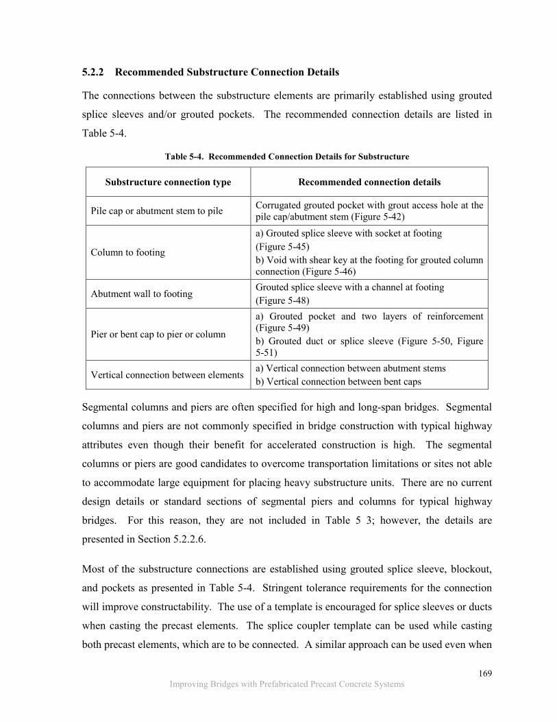
169
Improving Bridges with Prefabricated Precast Concrete Systems
5.2.2 Recommended Substructure Connection Details
The connections between the substructure elements are primarily established using grouted
splice sleeves and/or grouted pockets. The recommended connection details are listed in
Table 5-4.
Table 5-4. Recommended Connection Details for Substructure
Substructure connection type Recommended connection details
Pile cap or abutment stem to pile Corrugated grouted pocket with grout access hole at the pile cap/abutment stem (Figure 5-42)
Column to footing
a) Grouted splice sleeve with socket at footing (Figure 5-45) b) Void with shear key at the footing for grouted column connection (Figure 5-46)
Abutment wall to footing Grouted splice sleeve with a channel at footing (Figure 5-48)
Pier or bent cap to pier or column
a) Grouted pocket and two layers of reinforcement (Figure 5-49) b) Grouted duct or splice sleeve (Figure 5-50, Figure 5-51)
Vertical connection between elements a) Vertical connection between abutment stems b) Vertical connection between bent caps
Segmental columns and piers are often specified for high and long-span bridges. Segmental
columns and piers are not commonly specified in bridge construction with typical highway
attributes even though their benefit for accelerated construction is high. The segmental
columns or piers are good candidates to overcome transportation limitations or sites not able
to accommodate large equipment for placing heavy substructure units. There are no current
design details or standard sections of segmental piers and columns for typical highway
bridges. For this reason, they are not included in Table 5 3; however, the details are
presented in Section 5.2.2.6.
Most of the substructure connections are established using grouted splice sleeve, blockout,
and pockets as presented in Table 5-4. Stringent tolerance requirements for the connection
will improve constructability. The use of a template is encouraged for splice sleeves or ducts
when casting the precast elements. The splice coupler template can be used while casting
both precast elements, which are to be connected. A similar approach can be used even when

170
Improving Bridges with Prefabricated Precast Concrete Systems
a precast element is connected to a cast-in-place concrete component. The construction
sequence of using templates for a splice sleeve connection is shown in Figure 5-41.
Figure 5-41. The template used for a column splice with grouted splice coupler
5.2.2.1 Pile Cap or Abutment Stem to Pile Connection
The connection between the pile and precast abutment stem is shown in Figure 5-42. The
abutment stem includes a corrugated grouted pocket. The original abutment stem grout
pocket detail presented in Culmo (2009) is modified here to an inverted frustum shape. The
modification is for preventing grout spall when the grout is cracked or the bond fails due to
shrinkage. The cavity in the abutment stem can be formed with and without the corrugated
metal casing. However, the use of corrugated metal casing is helpful in fabricating as well
strengthening the concrete component.
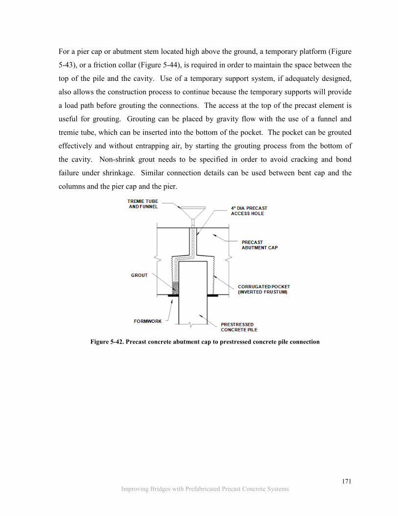
171
Improving Bridges with Prefabricated Precast Concrete Systems
For a pier cap or abutment stem located high above the ground, a temporary platform (Figure
5-43), or a friction collar (Figure 5-44), is required in order to maintain the space between the
top of the pile and the cavity. Use of a temporary support system, if adequately designed,
also allows the construction process to continue because the temporary supports will provide
a load path before grouting the connections. The access at the top of the precast element is
useful for grouting. Grouting can be placed by gravity flow with the use of a funnel and
tremie tube, which can be inserted into the bottom of the pocket. The pocket can be grouted
effectively and without entrapping air, by starting the grouting process from the bottom of
the cavity. Non-shrink grout needs to be specified in order to avoid cracking and bond
failure under shrinkage. Similar connection details can be used between bent cap and the
columns and the pier cap and the pier.
Figure 5-42. Precast concrete abutment cap to prestressed concrete pile connection

172
Improving Bridges with Prefabricated Precast Concrete Systems
Figure 5-43. Temporary support system for pile cap to pile connection (Source: Wipf et al. 2009a)
Figure 5-44. Adjustable friction collar fixed to the octagonal column to temporarily support abutment
cap or pier cap (Source: www.proscaffna.com)
5.2.2.2 Column to Footing Connection
The connection details recommended between a precast concrete column and footing are
1. Grouted splice sleeve with socket at the footing (Figure 5-45), and
2. Cavity or pocket with a shear key (Figure 5-46).
Use of a template is recommended for the grouted duct or splice sleeve type connections
while casting the precast elements. The template will allow stringent tolerances for enhanced
constructability. For the socket, shims can be used to place and level the column. High early
strength, non-shrink type grout needs to be specified for the splice sleeve. Providing a socket

173
Improving Bridges with Prefabricated Precast Concrete Systems
at the footing helps form the grout bed. Also, bridge plans should include the type of sleeve
and access to the grout inlet valve in addition to the socket depth and width dimensions. The
recommended grouted splice sleeve connection is shown in Figure 5-45.
Figure 5-45. Octagonal precast column to footing connection with grouted duct or splice sleeve and
socket connection
A precast concrete column to footing connection is shown in Figure 5-46. The connection
cavity can be designed to be smaller than the column cross section. This way the column can
rest on top of the footing without transferring the load to the reinforced connection. In this
case, the column is not embedded into the footing, hence the reinforcement is embedded into
the joint to transfer moment and shear. The bearing area of the column can be designed to
support the loads until the grouted void achieves the required strength. If the connection
cavity volume is large for neat grout, extended grouts or high early strength concrete can be
used. If extended grout and concrete is specified, adequate space needs to be provided to
place and consolidate the material. An example of such a connection is shown in Figure
5-47, where the connection cavity corners are beveled to provide adequate space for material
placement and consolidation. The detail shown in Figure 5-47 includes threaded bars;
however, column reinforcement can be extended where practical. A steel plate is attached to
the bottom of the connection cavity to retain the grout within the footing.

174
Improving Bridges with Prefabricated Precast Concrete Systems
Figure 5-46. Circular precast column to footing connection with grouted void/pocket and shear key
Figure 5-47. Column to footing connection with beveled void corners (Source: Photo courtesy of MDOT)

175
Improving Bridges with Prefabricated Precast Concrete Systems
5.2.2.3 Abutment Wall to Footing
A grouted splice-sleeve is an efficient way to allow for moment and shear transfer between a
footing and abutment wall. The connection can be made by providing a socket on the footing
for placing the abutment. The socket also helps to contain the grout. Shim packs can be used
to align and level the abutment as shown in Figure 5-48.
The size of the socket needs to be designed based on the space requirement for grouting the
splice sleeves and to have sufficient access to the splice sleeve grout inlet for grouting. Joint
waterproofing material can be used for reinforcement protection (Figure 5-48). To avoid any
conflict, the splice sleeves and the extended bars from the footing need to be aligned. As
discussed in Section 5.2.2, while casting the elements, requiring the use of a template of the
splice sleeves is recommended (Figure 5-41).
Figure 5-48. Precast concrete abutment to precast concrete footing
5.2.2.4 Pier Cap or Bent Cap to Pier or Column Connection
The connection detail recommended in the NCHRP-681 project is shown in Figure 5-49
(Restrepo et al. 2011). There are two grout pockets with two reinforcement layers. The bent
cap is shimmed, and the connection cavity is filled with extended non-shrink grout or high
early strength concrete through the opening at the top of the bent cap. This way construction
can continue without any interruptions. Connection reinforcement may be (1) bars extending

176
Improving Bridges with Prefabricated Precast Concrete Systems
from the column, (2) bars threaded into the column, or (3) bars that are inserted into the
column through drilled holes or corrugated ducts that are grouted.
Figure 5-49. Precast bent cap to precast column connection details with grouted pocket and two layers of
reinforcement (Source: Restrepo et al. 2011)
The connection between the columns and bent cap, shown in Figure 5-50, includes
corrugated ducts to connect the reinforcement extending from the columns. Establishing the
connection between the columns and the bent cap is challenging as it requires aligning a
group of bars that are extended from multiple columns. However, this detail has been
successfully implemented with the prefabricated units. The alignment difficulties can be

177
Improving Bridges with Prefabricated Precast Concrete Systems
reduced by using a template while casting the columns and bent cap. Use of a template will
also help control more stringent tolerances which will enhance the constructability. The
ducts are often pressure grouted, and the tubes are cut off. Proper vent tubes or outlet tubes
should be specified to ensure an air-pocket free connection. Implementing the detail shown
below (Figure 5-50) will require a pause in construction activities until grout develops the
required strength. If the project schedule will not allow the pause, an adjustable friction
collar (Figure 5-44) can be installed which allows load transfer directly from the bent cap to
the columns. Another option is the vertical splice duct connection, as shown in Figure 5-51,
that includes a capital on each column. The column capital can be designed to provide
sufficient bearing area for safe transfer of loads to the pier.
Figure 5-50. Grouted corrugated duct connection for precast bent cap to precast concrete column

178
Improving Bridges with Prefabricated Precast Concrete Systems
(a) 3D-view of the bent cap to column connection detail
(b) 2D-view of the bent cap to column connection detail
Figure 5-51. Vertical splice duct connection for precast bent cap to precast concrete columns (Source: Culmo 2009)

179
Improving Bridges with Prefabricated Precast Concrete Systems
5.2.2.5 Vertical Connection between Elements
A vertical connection between substructure elements or splicing is commonly used to control
the size and weight of substructure units such as abutment stems and bent caps. Splicing is
performed with grouted shear keys or reinforced concrete connections that transfer both
moment and shear (Figure 5-52, Figure 5-53 and Figure 5-54). A moment and shear transfer
connection between substructure units is recommended considering Michigan exposure that
develops large thermal cycles. The moment and shear will be generated by the back wall
sliding over the abutment under thermal cycles. Recommended details are presented in
Figure 5-52, Figure 5-53, and Figure 5-54. The difficulty of the reinforced connections is the
conflict between reinforcement during installation by lowering the abutment. In some of the
recently completed projects, splice reinforcement needed to be bent in the field to correct for
this conflict.
Figure 5-52. Grouted shear key and reinforced concrete connection details

180
Improving Bridges with Prefabricated Precast Concrete Systems
Figure 5-53. Abutment stem splice connection details
Figure 5-54. Bent cap connection details
5.2.2.6 Connection between Segmental Columns or Piers
Splicing is needed for columns and piers to control the weight of an individual element when
used in large or tall bridges. A column splice detail is shown in Figure 5-55 designed for
moment, shear, compression, torsion, and tension transfer. One of the difficulties with this
detail is maintaining the alignment of splice bars and couplers. This can be overcome by
using templates during precasting, as discussed in Section 5.2.2.

181
Improving Bridges with Prefabricated Precast Concrete Systems
Figure 5-55. Column splice with grouted splice coupler (Source: Culmo 2009)
Another option for vertical connection between precast elements is to use vertical post-
tensioning as shown in Figure 5-56. The connections are established using epoxy grouted
shear keys and post-tensioning that runs throughout the length of column. Bars are used to
connect and align each segment for stability during construction until the post-tensioning is
applied to compress the entire assemblage. The difficulty with this connection detail is to
maintain tolerances for an uneven fit at the match-cast connection. Another difficulty is to
maintain the post-tensioning duct alignment. Strict quality control measures can help with
the constructability challenges.

182
Improving Bridges with Prefabricated Precast Concrete Systems
Figure 5-56. Vertical connection of precast pier element (Source: Culmo 2009)

183
Improving Bridges with Prefabricated Precast Concrete Systems
5.3 GROUT MATERIALS
5.3.1 A Grout Selection Example
To demonstrate the recommended grout selection process discussed in the literature review, a
typical column to footing connection detail is selected. The details of the connection are
shown in Figure 5-57, Figure 5-58, and Figure 5-59. The site and schedule constraints and
geometric dimensions of the grout void are listed below.
• The grout is exposed to freeze/thaw considering Michigan exposure.
• The compressive strength requirement is 3.0 ksi to be achieved within 24 hours as per
the construction schedule.
• The working temperature range is 45 oF - 85 oF.
• The maximum grout working time requirement is 45 min.
• The grout void dimension is 30 in. × 30 in. × 42 in.
Figure 5-57. Elevation of the pier

184
Improving Bridges with Prefabricated Precast Concrete Systems
Figure 5-58. Plan view of the footing
Figure 5-59. Column to footing connection
The grouts listed in Section 2.4 of this report are considered for this application. Suitable
grouts that fulfill the freeze/thaw exposure requirement are listed in Table 5-5. However,
Sonogrout 10k cannot fulfill the compressive strength requirement of 3.0 ksi in 24 hours and
is eliminated for further consideration. SikaGrout 212 is eliminated because it cannot fulfill
the working temperature range requirement. The working time requirement can only be
fulfilled using Set 45 HW, EUCO SPEED MP, and S Grout. The Set 45 HW and EUCO
SPEED MP are magnesium phosphate grouts, which generate significant heat during the
hydration process. The size of the connection cavity is not suitable for grouts with high heat

185
Improving Bridges with Prefabricated Precast Concrete Systems
generation. Following these considerations, only S Grout remains suitable for this
application.
None of the identified grouts are suitable for placement in neat form due to the large cavity
volume. The S Grout can be extended using sand. However, the strength of extended grout
will be lower than documented in the table for neat grouts; yet water reducing admixture can
be specified to allow the grout to achieve high strength. With these modifications, it is
necessary to evaluate the rate of strength development, as well as the setting time, shrinkage,
and freeze/thaw resistance. Mock-up tests are needed to evaluate these properties. Finally,
following the grout selection, provisions need to elaborate on connection cavity surface
preparation as per the manufacturer’s recommendations.
Table 5-5. Recommended Grouts for the Given Project Requirements
Set 4
5 H
W
EUC
O S
PEED
MP
Mas
terf
low
928
S G
rout
Sono
grou
t 10k
Sika
Gro
ut 2
12
PRO
GR
OU
T 90
Proj
ect R
equi
rem
ent
Compressive strength (ksi) (min. 5.0 ksi at 24 hrs. as per AASHTO 2010)
1 day 6.0 6.0 4.0 3.5 1.6 3.5 4.7 3.0 3 days 7.0 6.5 5.0 5.0 3.8 - 5.6 7 days - 7.0 6.7 6.0 5.1 5.7 6.6 28 days 8.5 7.5 8.0 8.0 6.2 6.2 7.8 Initial setting time (min) 15 12 3 hrs 45 3 hrs 5 hrs 4 hrs 45
Filling depth/thickness for neat grout (in.)
Min 0.5 0.5 1 - 0.5 0.5 - Max 2 1 6 2 2 2 - Working temperature (oF) Min - - 45 40 65 45 - 45
Max 100 85 90 85 75 70 - 85 Freeze/thaw resistant YES YES YES YES YES YES YES YES Extend with aggregate YES YES YES YES YES YES - YES
5.3.2 Recommendation for Grout Selection
Proprietary and non-proprietary grouts and mixes can be specified for precast element
connections. The properties of proprietary grout are documented in Chapter 2 of this report
and evaluated for their usage and limitations. Proprietary grouts develop high early strength
and can possess non-shrink properties. A list of non-proprietary concrete mixes available in
literature is also presented in Chapter 2 of this report. Non-proprietary mixes such as high

186
Improving Bridges with Prefabricated Precast Concrete Systems
performance concrete (HPC) and ultra-high performance concrete (UHPC) have slow
strength development process compared to the proprietary grouts. Hence, non-proprietary
mixes may not suitable for strict project duration limitations.
The recommendations for grout selection are as follows:
1. A project designer needs to be equipped with all available grout/mortar types,
properties, application procedures, and limitations.
2. Connection detail design needs to be finalized following the review of material
properties, application procedures, and limitations.
3. Special provisions may include requirements for mock-up testing if the specific
grout/mortar identified for the project will be used with modifications and the
property data is not available.

187
Improving Bridges with Prefabricated Precast Concrete Systems
5.4 DEMOLITION METHODS AND EQUIPMENTS
The prefabricated bridge elements and systems recommended for Michigan are presented in
Section 5.1 of this report. Except the spliced girder systems and full-depth deck panel
systems, the remaining prefabricated components or systems are assembled onsite as simple
spans and then converted to continuous spans for live loads. Even when the bridge
superstructures are placed using SPMT or slide-in techniques, simple spans are used except
in a few projects such as the Sam White Bridge in Utah. In the case of full-depth deck panel
systems, the girders are designed as simple spans to carry the dead load of the girder and the
deck panels.
The demolition process will primarily involve removing continuity details between panels as
well as the girder ends following the reverse order of construction to make the spans simply
supported. The demolition procedures can follow the reverse order of construction for PBES
without compromising safety. Only the spliced girder bridges require using temporary
supports or counter weights if the reverse order of construction is followed for demolition.
In all cases, the demolition process requires detailed assessment of the bridge superstructure
and substructure condition and structural analysis to evaluate the stability of the structure
before planning and scheduling demolition activities. Bridge scour and/or substructure
deterioration can lead to instability issues and may require temporary supports. Therefore, it
is essential to assess the existing post-tensioned ducts (if applicable) prior to demolition of
bridges. A structurally sound grouted post-tension system may be assumed to be fully
bonded so that a sudden release of post-tension forces may not cause instability or hazardous
conditions (Lwin 2003).
Under the ABC concept, the demolition of the bridge starts after scheduling the construction
activities. By that time, the project team is knowledgeable of the equipment and the
construction technology that is planned. This is also an opportunity for the project team to
utilize most of the equipment already deployed at the site to be used for demolition activities.
This is further discussed later in the chapter under demolition techniques.
188
Improving Bridges with Prefabricated Precast Concrete Systems
Carefully planned and executed demolition could contribute to sustainability. When the
demolition is performed following the reverse order of construction, and the components are
in good condition following removal, there is a possibility of reuse.
5.4.1 Demolition Techniques
A demolition technique should be selected considering the parameters listed in Section 2.5 of
this report. Location and accessibility, shape and size of the structure, time constraints, and
maintenance of traffic (MOT) are some of the important parameters. An in- depth analysis of
those parameters for a particular site and bridge configuration needs to be carried out to
develop an efficient demolition process. Several demolition techniques are discussed in
Section 2.5 of this report. The PBES recommended in Section 5.1 are suitable for short and
short-to-medium span bridges; hence, the most appropriate techniques for demolition are the
following:
• Removing the superstructure or the entire structure using Self-Propelled Modular
Transporters (SPMTs),
• Removing the superstructure using horizontal skidding or the slide-out technique,
• Removing individual components, modules, or systems in the reverse order of
construction, and
• Using traditional bridge demolition techniques when none of the above techniques are
feasible due to site conditions and accessibility, bridge structural configuration or
condition, maintenance of traffic (MOT), schedule, availability of equipment, or a
combination thereof.
The above listed bridge demolition techniques need to be augmented by several other
operations, which are these:
• Drilling, sawing, and cutting,
• Hydrodemolition, and
• Demolition by hydraulic attachments (hammer, shear or pulverizer etc.).
The use of SPMTs, the skidding technique, or the removal of individual components/
modules/systems during demolition requires the spans to be simply supported. Semi-integral
abutments greatly simplify the demolition process. Further, they help to remove the

189
Improving Bridges with Prefabricated Precast Concrete Systems
superstructure without any damage to the abutment. However, if isolating the
components/modules/systems is required, hydrodemolition, hammering, concrete saw
cutting, metal cutting techniques or a combination thereof can be used. Details such as
reinforced concrete diaphragms and link slabs are used over the piers or bents to establish the
live load continuity between spans. The use of link slabs helps in the demolition process
while converting spans to simply supported.
Use of a regular concrete saw that can cut up to 12 in. is adequate. However, a reinforced
concrete cast-in-place diaphragm is often deeper than 12 in. and requires hydrodemolition,
hammering, concrete saw cutting, metal cutting techniques or a combination thereof to make
spans simply supported or to isolate the components to facilitate the removal process.
The continuity between individual components/modules/systems is established using grouts,
cast-in-place concrete (special mixes), post-tensioning or a combination thereof in
conjunction with unreinforced or reinforced connection details. Saw cutting helps in
isolating the individual components/modules/systems to facilitate the demolition. A few
examples of saw cutting are shown in Figure 5-60 to demonstrate the capabilities and state-
of-the-art practices.
Figure 5-61 shows partial and full removal of bridge deck using the hydrodemolition
technique. Hydrodemolition can be used to remove small patches of concrete for repair or
rehabilitation activities (Calabrese 2000). During replacement of full-depth deck panels,
hydrodemolition is a better option for removal of grout or concrete at the blockouts without
damaging the girders and shear studs. Hydrodemolition should follow technical guidelines
related to wastewater control and debris removal for a better demolition process (Winkler
2005). In addition to these methods, the use of a hammer and a pulverizer for bridge
demolition is shown in Figure 5-62.

190
Improving Bridges with Prefabricated Precast Concrete Systems
(a) Saw cutting of a bridge deck
(Source: http://www.476blueroute.com)
(b) A saw cut section of a segmental bridge
(Source: Lwin 2003)
Figure 5-60. Saw cutting technique
(a) Concrete removal by hydrodemolition
(Source: http://nationalhydroinc.com)
(b) Hydrodemolition of a bridge deck
(Source: http://www.blasters.net)
Figure 5-61. Hydrodemolition technique
(a) Hammer
(b) Pulverizer in action
Figure 5-62. Demolition by hammer and pulverizer

191
Improving Bridges with Prefabricated Precast Concrete Systems
5.4.1.1 Self-Propelled Modular Transporters (SPMTs)
This technique has been successfully used for bridge superstructure removal and
replacement. The use of the technology is limited due to the initial cost and site constraints
such as accessibility, space requirement, and utilities (FHWA 2007). Use of SPMTs to
remove the bridge for demolition is justified when the same equipment is used for
replacement. When using an SPMT for the removal of deteriorated bridges, the bridges
should be carefully analyzed for structural integrity, structural vibrations and stability,
especially in establishing the SPMT support locations. As discussed above, the
superstructure continuity details need to be removed for effective use of this technique.
5.4.1.2 Horizontal Skidding
This technique has been successfully used for bridge replacement. The structure can be slid
out and then either demolished or deconstructed afterwards. At the same time, the new
bridge can be slid into the position. Deteriorated bridges need to be carefully analyzed for
structural integrity and stability by considering the temporary support locations. This is a
cost-effective method only if the new bridge is replaced using the same technique. The use
of this technique is mainly governed by the site condition, including space availability for
accommodating both the replacement bridge and the old bridge. Further, the significance of
the feature intersected is a major parameter because the removed bridge superstructure has to
be demolished or deconstructed while the spans are over the feature intersected.
5.4.1.3 Removing Individual Components, Modules, or Systems in the Reverse Order of Construction
Demolition of bridges by removing individual components, modules, or systems, requires the
spans to be simply supported. The demolition process can be planned by studying the
construction process, as-built details, and condition of the bridge. A thorough assessment
needs to be performed considering the existing condition before saw cutting the connections
to assure the safety of the structure. As discussed earlier, use of semi-integral abutments and
link slabs greatly simplifies the demolition process. Isolating individual elements by cutting
through field cast connections can be accomplished using concrete saws.

192
Improving Bridges with Prefabricated Precast Concrete Systems
An example of removing a box-beam is shown in Figure 5-63. This method allows using
traditional equipment to perform demolition operations by adhering to site constraints such as
removing debris and controlling dust. In general, the lifting devices need to be attached close
to the component supports of the existing bridge. The components can be taken away from
the site and be reused or demolished later on. Another advantage of this method is that the
equipment deployed in the demolition procedure can also help with the construction.
Figure 5-63. Removal of a box-beam
5.4.2 Demolition of the Recommended Bridge Systems
Based on the bridge superstructure configuration, the recommended bridge structural systems
are categorized into three major groups. The demolition steps are broadly divided into
superstructure and substructure removal as shown in Figure 5-64. Only the full-depth deck
panel system requires three major steps in the demolition process. The removal of safety
barriers is not explicitly discussed even though it should be the first step of the demolition
process as shown in Figure 5-65.

193
Improving Bridges with Prefabricated Precast Concrete Systems
Figure 5-64. Demolition hierarchy of the recommended bridge systems
Figure 5-65. Removal of safety barriers
5.4.2.1 Demolition of Full-Depth Deck Panel Superstructure
Demolition of full-depth deck panels with post-tensioning is challenging compared to the
other systems recommended in Section 5.1. In certain cases, depending on the condition and
size of the structure, a detailed analysis of the demolition process should be performed
including cutting of post-tensioning and carrying out a time-dependent analysis of the
system. The following is the major steps involved in a demolition process.

194
Improving Bridges with Prefabricated Precast Concrete Systems
• Assess the condition of the bridge superstructure and substructure.
• Evaluate the scour state, which may lead to instability of the structure.
• Assess the existing condition of the grouted tendon ducts to prevent abrupt changes in
post-tension load transfer when the ducts and the strands are cut. If the ducts are fully
grouted, the load transfer is gradual and will not create safety concerns.
• Conduct a detailed analysis of the demolition process considering the condition of the
bridge, demolition sequence, temporary supports, and position of the lifting devices.
• Remove overlay to locate the blockouts and panel-to-panel connections (required
only when deck panels are replaced).
• Locate blockouts with shear studs, and cut around the blockouts by using a concrete
saw or hydrodemolition. Concrete that encases the shear studs can be removed by
using a hammer or hydrodemolition. Use of jack hammer is not recommended
because it may damage the girders.
• Cut transverse connections first and then cut the longitudinal connections of the
panels using a concrete saw. If only the deck is to be replaced, then the girders
should be spared while cutting or removing the panel. Hence, cut depth needs to be
carefully adjusted. Cutting post-tensioning ducts and strands should not yield to any
instability situations as the girders are designed to be simply supported while carrying
the dead load of deck panels.
• Remove panels by lifting once the deck is fully detached from the girders (Figure
5-66).
• Cut off existing shear studs if it is necessary (Figure 5-66). New studs can be welded
(if steel girders are used in the superstructure or steel plates are provided in the top
flange of the concrete girders). It is advised to protect the studs as much as possible.
If a limited number of studs are needed to be replaced, drilling and installing new
studs in a concrete girder is advised.
• Remove the girders after panels and the continuity detail over the piers are removed;
do this by cutting or through other demolition techniques as discussed at the
beginning of the section.

195
Improving Bridges with Prefabricated Precast Concrete Systems
(a) Lifting of a deck panel (b) Cutting off the existing steel shear studs
Figure 5-66. Replacement of deck panels (Source: Wenzlick 2005)
5.4.2.2 Demolition of a Superstructure with Modular Elements or Systems
The bridge superstructure elements or systems are first placed as discrete simply supported
components. Then the continuity between components and over the piers or bents is
established. Demolition is performed following the reverse order of construction after
thoroughly assessing the condition of the bridge superstructure and substructure. The
following major steps are recommended.
• Assess the condition of the bridge superstructure and substructure.
• Evaluate the potential for scour, which may lead to instability of the structure.
• Conduct a detailed analysis of the demolition process considering the condition of the
bridge, demolition sequence, temporary supports, and position of the lifting devices.
• Remove the continuity details over the piers or bents making the spans simply
supported. Potential approaches of removing continuity detail are discussed at the
beginning of this section.
• Saw cut the connections between individual elements or systems.
• Attach lifting devices at predefined locations and remove the components.

196
Improving Bridges with Prefabricated Precast Concrete Systems
5.4.2.3 Demolition of Bridge Substructure
Demolition of substructures needs to be evaluated after considering the size and weight of the
components and the potential for scour at the piers and abutments. Demolishing with
mechanical methods, such as hammers and pulverizers, is recommended based on the size
and weight of the substructure units. Removal of debris can be minimized by performing
demolition in the reverse order of construction. This is feasible if segments are used for
abutment wall and bent caps to reduce weight.
The substructure components, such as bent caps and columns, can be brought down as a
single unit by cutting at the footing level. Afterwards, they can be cut into pieces that are
small enough to be transported. This technique was used in the demolition of Cooper River
bridge (Figure 5-67) and demolition of the I-5 Bridge over the Willamette River in Eugene,
Oregon (Figure 5-68).
Pile demolition can be carried out by mechanical methods after deciding on a suitable depth
of removal. As recommended in FDOT Standard Specification for Road and Bridge
Construction, removal depth of piling should be the deepest described in the permit or other
contract documents, but not less than 2 ft below the finish ground line.
Figure 5-67. Demolition of a bent cap and columns as a single unit (Source: SCDOT)

197
Improving Bridges with Prefabricated Precast Concrete Systems
Figure 5-68. Column and pier walls are sawn off and lifted out for demolition (Source:
http://www.mcgee-engineering.com)

Improving Bridges with Prefabricated Precast Concrete Systems
Intentionally left blank

198
Improving Bridges with Prefabricated Precast Concrete Systems
6 A CONSTRUCTABILITY MODEL FOR ABC PROJECTS
An ABC constructability model is developed based on constructability basics presented in
Chapter 2 and performance, challenges, and lessons presented in Chapter 3. The model is
structured in a list of questions. The model shown in tabular form below is intended for the
project development and delivery team’s review before construction commences.

199
Improving Bridges with Prefabricated Precast Concrete Systems
6.1 TO BE REVIEWED BY THE PROJECT DEVELOPMENT TEAM
DESCRIPTION YES NO N/A Remarks I BIDDABILITY 1. Are agreements and any coordination needs in place with appropriate agencies/utilities/other
affected parties?
2. Are permits executed, and have all requirements identified been addressed on the plans (DEQ, Coast Guard, waterway, RR, regulatory, local agency, FAA, etc.)?
3. Is the environmental classification complete? 4. Is the environmental certification complete?
5.
Did you consider involving all stake holders (designer, contractor, fabricator, utility providers, township officials, state and local police, regulating agencies etc.) during the construction process to mitigate the risks, to identify and revise the methods of construction, and to deliver the project on time?
II BUILDABILITY A. Site Investigation 1. Has a current site survey been completed (horizontal & vertical controls)? 2. Was subsurface exploration performed? (soil boring, water table, etc.) 3. Was there a utility investigation including overhead lines? 4. Are the existing drainage features adequate? 5. Were overhead, underground, and other bridge supported utilities considered during the
design phase?
6. Has the level/amount of deterioration identified during the original scope been rechecked? A recheck should occur if the original scope is more than 2 years old.
7. Did you consider locating the fabrication facility at or near the job site to minimize the construction cost and the impact of load restrictions?
8. Did you analyze the site constraints associated with potential construction methods? 9. Is this project a candidate for SPMT construction?

200
Improving Bridges with Prefabricated Precast Concrete Systems
DESCRIPTION YES NO N/A Remarks II BUILDABILITY
B. Right of Way 1. Have any special access requirements been addressed? 2. Are private facilities located within the R.O.W. that need to be addressed? C. Construction Staging 1. Did you consider using BIM in the design and construction of this project? 2. Have local ordinances been investigated and permits secured? 3. If applicable, have permit requirements been noted? 4. Did you consider pre-event meetings to examine every step involved in the construction? 5. Did you consider preparing a contingency/emergency plan for unforeseen site conditions? 6. Does your emergency response plan include a checklist, contact information, contracting
alternatives, information sharing, and decision making hierarchy? 7. Is the envisioned construction method(s) compatible with the site constraints? 8. Did you consider involving the heavy lift contractor (i.e. SPMT) during design to facilitate
the construction process?
9. Are skilled workers available for the project? 10. Did your design team review the installation details? 11. Have you incorporated unique design and construction aspects into the project? 12. For the unique aspects, have you developed an assessment and data collection plan? D. Maintenance of Traffic (MOT)
1. Have items been reviewed on the Transportation Management Plan Project Development Checklist to determine what items are needed?
2.
Did you review transportation logistics (i.e., practical weight limits for transporting, lifting, and placing.)? Did you consider alternative means of access to accommodate any constraints? Are the constraints clearly articulated in the specifications or on the plans?
3. Did you consider involving the contractor in developing MOT plans?

201
Improving Bridges with Prefabricated Precast Concrete Systems
DESCRIPTION YES NO N/A Remarks E. Schedule 1. Have the regulatory permit restrictions been considered? 2. Did you consider incentive/disincentive provisions? 3. Did you analyze which delivery method minimizes construction time? 4. Does the standard and special specifications used in earlier projects provide sufficient
clarity? Note: using tested and standard specifications minimizes probability of error and reduces construction rework.
F. Special Materials/Conditions 1. Has the presence of asbestos, hazardous waste or toxic materials been identified and
addressed?
2. Are you using special concrete and/or grout specifications on this project? 3. Did you consider the compatibility between specified material and design detail
requirements? (e.g., gap size to be filled )
4. Do quality assurance and quality control provisions in construction specifications adequately address every stage of the construction process?
5. Did you consider using lightweight material for fabricating lighter sections? 6. Have you incorporated special materials and specifications? 7. For the special materials and specifications, have you developed an assessment and data
collection plan?

202
Improving Bridges with Prefabricated Precast Concrete Systems
DESCRIPTION YES NO N/A Remarks G. Fabrication
1. Did you consider standardizing the precast components to improve the efficiency of fabrication and installation?
2. Did you consider alternate geometries and details for connections between bridge elements or systems to improve construction efficiency?
3. Did you consider issues with moisture ingress for joints between bridge elements or systems to improve durability?
4. Did you consider installation and removal of formwork? Or did you use details that do not require formwork for connections and closures?
5. Did you consider using larger precast elements which will reduce the time and cost of fabrication, delivery, and erection?
6. Did you consider developing protocols using the BIM model or otherwise for as-built inspection?

203
Improving Bridges with Prefabricated Precast Concrete Systems
6.2 TO BE REVIEWED BY THE PROJECT DELIVERY TEAM
DESCRIPTION YES NO N/A Remarks II BUILDABILITY A. Site Investigation 1. Has the Engineer performed a site visit?
2. Has a sufficient field investigation been conducted to ascertain that the proposed contract work can be performed?
3. Has the site been evaluated for suitability with the identified construction method? B. Right of Way 1. Is there sufficient R.O.W. available for all operations? C. Construction Staging 1. Is the project phased to provide reasonable work areas and access? 2. Are widths of work zones and travel lanes adequate? 3. Are heights of the work zones and travel lanes adequate? 4. Does staging cause special conditions (structural adequacy/stability, etc.)?
5. Are any proposed adjacent contracts, restrictions, and constraints identified and accounted for?
6. Can the details as shown on the plans be constructed using standard industry practices, operations, and equipment?
7. Can construction-staging operations be carried out according to the maintenance of traffic plan?
8. Can drainage be maintained through each stage?
9. Did you consider simulating or testing the lift operation prior to the scheduled move? Did you consider using advanced positioning sensors such as GPS during the PBES assembly?
10. Did you develop a plan of action in case damage occurred during lift operation?
11. Did construction specifications define mixing, placing, and curing procedures for grout and/or special concrete?

204
Improving Bridges with Prefabricated Precast Concrete Systems
DESCRIPTION YES NO N/A Remarks
12. Did you evaluate the suitability of the construction specifications for grouting and/or special concrete operations related to connection details?
13. Did you consider/analyze tolerance issues as they relate to pre-stress/post-tensioning operations?
14. Did you carefully analyze tolerance issues related to the assembly and/or connectivity of the precast components? (e.g., review/analysis of tolerance issues related to the locations of shear connectors when using precast deck panels) Did you check elevations?
15. Did you evaluate the compatibility of the construction method(s) with the site constraints? (e.g., the working radius and location of cranes)
D. Maintenance of Traffic 1. Are there adequate provisions for pedestrian access and abutting properties? 2. Are there adequate provisions for emergency providers? 3. Are there adequate provisions for water traffic? 4. Have delays been estimated and provisions made to minimize them? E. Schedule 1. Is the length of time and production rate for work reasonable? 2. Are there any restricted hours, and have their impact on schedule been considered?
3. Have other contracts in the area been considered along with how they affect this project (i.e., trucking routes, accessibility, and traffic control)?
4. Does the schedule consider long lead-time for ordering materials? 5. Is the shop drawing review time considered? 6. Are night and weekend work proposed, and if so, are the impacts considered? 7. Is the sequence of construction reasonable? 8 Have seasonal limits on construction operations been considered and accounted for? 9. Does the utility relocation schedule fit into the overall schedule?

205
Improving Bridges with Prefabricated Precast Concrete Systems
DESCRIPTION YES NO N/A Remarks F. Special Materials/Conditions 1. Have soil erosion/sedimentation issues been addressed? 2. Are any special (unique/proprietary) materials, methods or technologies required for the
contract? 3. Have all environmental constraints been avoided and restrictions been adhered to? 4. Did construction specifications define mixing, placing, and curing procedures for grout
and/or special concrete?
5. Did you evaluate the suitability of the construction specifications for grouting and/or special concrete operations related to connection details?
G. Staffing 1. Are there any special operations that would require inspection specialists? 2. Is the budget adequate to cover construction engineering costs for the project? III General 1. Have you incorporated unique design, construction, and material aspects to the project?
2. If the answer to the above question is ‘yes,’ have you developed an assessment and associated data collection plan for the unique design, construction, and material aspects of the project?

206
Improving Bridges with Prefabricated Precast Concrete Systems
6.3 SUMMARY
As accelerated bridge construction (ABC) continues to gain acceptance across the U.S.,
constructability reviews will assist in ensuring that projects are completed in the most
efficient and cost effective manner by simply reducing errors. In this study, a comprehensive
ABC constructability model was developed based on constructability basics and challenges
and lessons learned reported in the literature. Two difficulties faced in developing the ABC
constructability model are as follows:
• a Limited access to a small amount of case study reports on ABC projects because ABC
is new to the industry, and
• Finding adequate and necessary details on some of the case studies documented in the
literature.
Nevertheless, the constructability model presented in this report is a significant resource for
future ABC implementations by providing guidance to project planners, designers, and
constructors. The model will need to be fine-tuned as more ABC projects are completed and
documented. A post-construction program for ABC projects that properly documents
challenges and lessons learned will provide the data for continual refinement/revision of the
constructability model.

Improving Bridges with Prefabricated Precast Concrete Systems
Intentionally left blank

207
Improving Bridges with Prefabricated Precast Concrete Systems
7 SUMMARY, CONCLUSIONS, AND RECOMMENDATIONS
7.1 SUMMARY AND CONCLUSIONS
The project goal was to analyze prefabricated bridge elements and systems (PBES) and
accelerated bridge construction (ABC) technology for implementation; it was also to develop
technology implementation recommendations to assure constructability, durability,
repairability, and maintainability. In addition, recommendations for follow-up projects are
described in order to further improve effectiveness and efficiency of new technology
implementations.
The first task was to review and synthesize the state-of-the-art practices in using (1) PBES in
ABC, (2) connection details between prefabricated components, (3) available cementitious
grout material for the connections and their application procedures, (4) equipment and
methods for accelerated construction and demolition, (5) constructability review process
(CRP) or constructability program, and (6) decision-making models. The synthesized
knowledge base compiled from the literature review developed the basis of the subsequent
tasks. The subsequent tasks were to develop recommendations for PBES and connection
details for Michigan exposure, developing a Michigan-specific ABC decision-making
process, a constructability review checklist for ABC implementations, and a special
provision template for grout selection and application. The literature review is presented in
Chapter 2.
The performance of earlier ABC implementations was reviewed. Previous ABC
implementations were categorized into three groups:
(1) full-depth deck panel systems,
(2) deck integrated prefabricated modules (box-beams) to develop side-by-side box-
beam systems, and
(3) Self Propeller Modular Transporters (SPMT), or the slide-in technique, to move a
complete bridge superstructure into place.
Recommendations are presented in Chapter 3 to assure the long-term durability of PBES.
Recent ABC projects were also reviewed, and lessons for future implementations are
described. The lessons learned were synthesized and categorized as (1) project planning,

208
Improving Bridges with Prefabricated Precast Concrete Systems
design and tolerances, (2) precast element fabrication procedures, and (3) construction
operation and methods. One outcome of analysis of recent projects together with the
synthesis provided in the literature review was the basis for the development of a
constructability review checklist for ABC projects.
To advance the available decision-making processes, a multi-criteria decision-making
process and the associated software platform was developed. The software is called Michigan
Accelerated Bridge Construction Decision-Making (Mi-ABCD) tool that compares the
Accelerated Bridge Construction (ABC) to Conventional Construction (CC) alternatives for a
particular project. The decision-making process incorporates project-specific data and user-
cost and life-cycle cost models to provide input to the users with quantitative data. The
software platform was developed on Microsoft Excel and Visual Basic for Applications
(VBA) scripts. A user manual was also prepared and included in Appendix E. The multi-
criteria decision-making process developed during this project provides solutions to many
issues in ABC decision-making. The decision-making framework calculates the preference
rating of each construction alternative. The contribution of major parameters to the
preference ratings is also displayed. The decision-making platform features developed in
this project is a significant advancement over the available decision-making models.
Connection details for the prefabricated bridge elements and systems and grout or special
mixes suitable for the connections and for the Michigan climate are developed and included
in the report. Following the synthesis of the state-of-the-art practices and performance and
lessons learned from ABC implementations, PBES with potential for immediate
implementation are classified. Implementation potential for PBES is based on
constructability, maintainability, reparability, and durability (CMRD). Suitable connections
between the PBES are identified considering Michigan exposure, load transfer mechanism,
constructability, durability, dimensions and tolerances. The PBES and associated
connections recommended for Michigan, attributes of PBES, connection details, formwork
for grout or special mix placement, construction complexities, and additional limitations are
presented in Chapter 5. Above all, standard details for longitudinal connections at the deck
level are developed for bridge superstructures with precast, prestressed concrete girders.

209
Improving Bridges with Prefabricated Precast Concrete Systems
Addressing the constructability issues due to weight of substructure components, reduced-
weight options are identified and presented in Chapter 5.
Nonspecific grout or special mix recommendations for a connection are not practical because
the material selection needs to be based on project or design specifics. Examples of related
project specifics are (1) site specific exposure conditions, (2) grout pocket dimensions, (3)
application procedures and limitations, (4) curing requirements and also (5) grout properties
such as compressive strength, volume stability, initial setting time or working time, and
working temperature range. It is recommended that grout needs to be tested and evaluated
for the particular application before field implementation. In order to streamline the grout
specification process, a template of special provisions for grout selection and application is
developed and presented in Appendix J. Further, development of a database of material
properties suitable for the connection between prefabricated components is recommended.
This database needs to be available to designers as discussed and presented in Chapter 5.
An ABC constructability review checklist is compiled. The checklist will help guide the
project development and delivery teams in constructability assessments before initiating the
design process. The checklist will also help reduce errors as observed in earlier ABC
implementations. It can be a project management, scheduling, and cost control tool.
7.2 RECOMMENDATIONS
The recommendations developed in this project are specific to (1) the Michigan specific
decision-making platform, (2) PBES suitable for Michigan, (3) PBES connection details, (4)
grout and special concrete mix specifications, and (5) the constructability review checklist.
1) The next version of the decision-making platform capability needs to include
comparisons of different ABC alternatives with conventional construction.
2) The PBES suitable for Michigan are categorized as i) suitable for immediate
implementation and ii) suitable for implementation with additional investigations.
• The PBES suitable for immediate implementation are as follows:
o PC I and bulb-tee girders: A widely used girder type with standard details. In the
context of ABC, these multigirder systems can only accommodate the full-depth
deck panels.

210
Improving Bridges with Prefabricated Precast Concrete Systems
o Full-depth deck panels with transverse prestressing and longitudinal post-
tensioning: The transverse prestressing is required for panel crack control. An
accurately designed and constructed deck system with longitudinal post-
tensioning will achieve superior durability performance. Durability performance
failures are often related to flawed grouting of connections. Other problems
reported are related to repair and rehabilitation difficulties due to the post-
tensioning. With regard to limitations on repair and rehabilitation with the post-
tensioning, it is best to implement this system at sites where girder damage (e.g.,
high-load hits) is unlikely.
• Decked bulb-tee girders: Bridge can be designed with or without an overlay. The
forms for casting the precast bulb-tee girders can be modified for the decked
section. Problems include the performance weakness of the system associated
with the empirically designed longitudinal connections. This report addresses this
by presenting rationally designed standard longitudinal connection details.
• Decked box beams: This system is recommended based on the Michigan DOT’s
favorable experiences. The difficulty is the multi-step fabrication process
required for casting this section. Box beams are standardized; hence, the
formwork is available. Fabrication difficulties can be overcome by modifying the
box beam formwork for the decked sections. Similar to all PBES, durability
performance of the decked box section is also controlled by the details and
grouting quality of the longitudinal connections. Rationally designed standard
details for flexure-shear transfer connections is also presented in this report.
• Decked steel girder system: This system is developed through a SHRP II project.
The system is non-proprietary, and fabrication appears simple. The shallow depth
makes the section suitable for sites with underclearance limitations. Further, the
construction does not require any specialized equipment. To be cost effective, the
section steel girder fabrication and precasting of the deck can be performed at a
nearby staging area. Durability performance of the system is again controlled by
the details and grouting quality of the longitudinal connections. Connection
redesign to accommodate both moment and shear transfer is recommended.

211
Improving Bridges with Prefabricated Precast Concrete Systems
• Precast abutment stem: Two different sections are recommended. The primary
limitation is the weight of the stems. To minimize the weight, a stem fabricated
with cavities is recommended. The cavities can be filled with concrete following
placement. Another option is segmental stems that are spliced in the field. The
segmental stems can be utilized for sites with limited access or space.
• Precast columns: Rectangular, square, and octagonal sections are recommended
considering fabrication and transportation difficulties with circular sections. On
the other hand, the precast industry needs to innovate in order to manufacture
circular products efficiently and cost effectively, for example, by using centrifugal
force during concrete placement to form the circular cross-section.
• Precast pier/bent cap: The primary limitation is the weight of the segments. Bent
caps can be fabricated in different lengths to overcome the weight limitations.
Reduced-weight alternatives are presented in the report. Some state agencies
have developed standard details for pier and pier caps, two column bent, or a three
column bent. Developing standard pier and bent cap details for MDOT
applications is recommended.
• The recommended PBES strategies that require additional investigation before being
implemented in Michigan are as follows:
• Precast adjacent box beams: This bridge system has been implemented since the
1950’s. Additional investigations and subsequent redesign is required to resolve
durability performance problems with the girder, longitudinal joints, and the deck.
• Inverted-T precast slabs: This system, with high span-to-depth ratio, is suitable
for projects with underclearance limitations. The connection between the units is
prone to cracking. The NCHRP-10-71 project proposed new details to prevent
cracks from forming. These proposed details have not been tested nor their
performance monitored. Further investigation is required prior to recommending
the system.
• Northeast Extreme Tee (NEXT) D beams: This section possesses higher load
carrying capacity than standard double tee girders. The concerns related to

212
Improving Bridges with Prefabricated Precast Concrete Systems
undefined live load distribution and the lack of optimality of the cross-section
requires further investigation.
• Precast pier/bent cap with cavities: The sections developed with cavities are of
reduced weight. However, the section is not widely used and requires further
investigations. Prestressing was also identified as an option to increase bend cap
capacity; thus, the section can be reduced for lower weight. This requires a
detailed study on performance and cost comparison.
• Precast segmental piers: Using segmental piers resolves problems associated with
weight and size, transportability, site accessibility, and space constraints. Further
investigation is required to identify a suitable section type and size for short and
short-to-medium span bridges.
3) Considering i) Michigan exposure conditions, ii) the load transfer mechanism of the
connections, iii) constructability, iv) connection dimensions and tolerances (to ensure
construction quality), and v) other details such as formwork for grouting, the following
details are recommended.
• The superstructure connection details are classified into five groups given below:
• Transverse connection at the deck level: This detail is typically used in the full-
depth deck panel system. Transverse connection between panels is typically
unreinforced and requires post-tensioning for moment and shear transfer.
Considering the tolerances, space for grouting, and adequate confinement of the
grout to transfer shear, the recommended connection details are presented in
Section 5.2.1.1.
• Longitudinal connection at the deck level: Longitudinal connection at the deck
level requires two layers of reinforcement for moment transfer. The standard
details developed by a rational design process are presented in Section 5.2.1.2,
and they are recommended for systems such as full-depth deck panels, decked
bulb-tee, decked box-beam, and NEXT D beams. The reinforced joint can be
formed using high early strength concrete or suitable grout with properties
compatible to concrete.

213
Improving Bridges with Prefabricated Precast Concrete Systems
• Deck-to-girder connection: This detail is typically used in a full-depth deck panel
system to connect the panel to the girder. In Section 5.2.1.3, connection details
are recommended for both steel and concrete girder systems. A panel support
system and flexible formwork are recommended.
• Continuity detail over a pier or a bent: Details for a full moment connection and
link slabs over a pier or bent are recommended. Section 5.2.1.4 presents the
details and a discussion of limitations in using such details. Considering the
demolition process discussed in Section 5.4.2, link slabs over the piers and bents
are recommended.
• Continuity detail at abutment: A semi-integral abutment detail with an approach
and sleeper slab is recommended. This recommendation is based on future bridge
superstructure replacement needs and associated design, construction, and
demolition simplicity. Details are presented in Section 5.2.1.5.
• The substructure connections are classified into five groups as given below:
• Pile cap or abutment cap to pile: The recommended connection details presented
in Section 5.2.2.1 include moment and shear transfer connection with grouted
pockets formed with corrugated metal at the pile cap or abutment cap. In this
connection, an access hole at the top of the pile cap or abutment cap is required
for grout placement by gravity. A temporary support system is also recommended
for the pile cap or abutment cap so that the construction activities can be
performed without delay, while the grouted connection gains sufficient strength.
However, vibration propagating from construction activities may impact grout
strength and interface bond development at the connection.
• Column to footing: Two types of connection details are recommended in Section
5.2.2.2. These are (1) a grouted splice sleeve and a socket at the footing level and
(2) a pocket connection with a shear key. Neat grout is recommended for splice
sleeves and extended grout; high early strength concrete is recommended for
larger voids in a pocket connection.

214
Improving Bridges with Prefabricated Precast Concrete Systems
• Abutment wall to footing: A grouted splice sleeve connection is recommended in
Section 5.2.2.3. Alignment of extended rebars with the splice sleeves may present
difficulties during prefabrication.
• Pier cap or bent cap to pier or column: Three connection types are recommended
in Section 5.2.2.4. These are (1) a grouted pocket with two layers of
reinforcement, (2) a grouted corrugated duct connection, and (3) a vertical splice
duct connection. The details with a designed bearing surface between components
allow construction activities to proceed without delay while grout or special
mixes achieve the minimum required strength. However, vibration propagating
from construction activities may impact strength and interface bond development
at the connection.
• Vertical connection between elements (splice): Splicing of components can
control the size and weight of substructure units as discussed in Section 5.2.2.5.
The details recommended are those that transfer both moment and shear. The
construction difficulties presented in Section 5.2.2.5 include space limitations and
conflict between reinforcement. In recently completed projects, splice
reinforcement was in conflict and needed to be bent at the field. With the
knowledge of construction difficulties, the designers and fabricators can resolve
potential conflicts during the design phase.
4) Grout selection, application procedures, and curing requires consideration of (1)
connection details, (2) strength, serviceability, and durability requirements, (3) site
exposure, and (4) construction schedule. A grout property database, if developed, will
significantly simplify the preparation of special provisions. A template of detailed
special provisions to address grout selection, testing, application, curing or protection,
quality control, and reporting is developed and included in Appendix J.
5) The recommendations to enhance constructability are as follows:
• Implement the constructability review checklist in ABC projects as it can play a
significant role in guiding the project planners, designers, and constructors.
• Refine the constructability review checklist using “Total Quality Management”
principles and the data collected during recent ABC projects.

215
Improving Bridges with Prefabricated Precast Concrete Systems
• Develop a post-construction report template for ABC projects to properly document
the difficulties and lessons learned as part of a “Total Quality Management” process.
7.3 RECOMMENDATIONS FOR IMPLEMENTATION
During this project, several tasks were identified that will expedite MDOT’s implementation
of PBES. These tasks are described below:
1) The Michigan-specific ABC decision making platform needs to be upgraded to include
comparisons of ABC alternatives.
2) In order to promote a system-wide PBES implementation, an inventory-specific PBES
can be developed including substructure components for MDOT and local agency
bridges. A Michigan bridge inventory can be classified with respect to span ranges,
skew, and additional inventory classification parameters. Bridges can be classified with
respect to span [short (<60 ft), short-to-medium (60 – 130 ft), and medium span (130 -
260 ft)] and skew [skew <200, 200< skew <300, 300< skew <450, 450< skew <600]. A
project can be initiated to identify and specify PBES option(s) appropriate for each
classification. Substructure components can also be specified, and conceptual
configurations and details can be developed. The conceptual configurations will help
resolve some of the difficulties such as component weight, transportation, and connection
details. Several conceptual substructure configurations are identified:
i) Discrete piers to support girders without the need for a continuous bent cap. The
design requires identifying and evaluation of transverse girder end diaphragm
options for stability and developing design examples and details.
ii) Discrete piers to support girder ends with integrated backwall to develop semi-
integral systems. Precast wall panels can be used with discrete columns to retain
the backfill. This detail requires developing design details, testing, and
verification, and developing design examples.
iii) Limited length bent caps (e.g., bent caps that are supported by single, two, or
three columns).
iv) Prestressed bent caps.
v) Precast approach slabs for semi-integral bridges.

216
Improving Bridges with Prefabricated Precast Concrete Systems
This proposed project will be the intermediary step towards standardizing PBES and
associated substructure components.
3) There is a lack of information available to the designer in specifying grout or special
mixes for the connections between prefabricated components. The current practice of
specifying the material in general terms, such as non-shrink grouts, creates difficulties
during construction. Development of a material database is recommended for use of
design engineers and contractors.
4) The increase use of PBES within MDOT and local agency inventory requires updated
inspection procedures to include processes specific to prefabricated bridge systems. The
updated inspection and reporting procedures will require including child tables to already
existing parent tables such as deck and substructure. Information related to superstructure
type such as a full-depth deck, a deck with modular elements, and a deck with modular
systems can be included in the child table under the deck. An additional table may
include component, connection, and continuity detail-specific ratings and inspector
comments. Extending the inspection database in this fashion helps in implementing an
effective and efficient bridge management program specific to PBES. Further, PBES in a
few cases will require the use of advanced NDE techniques for inspection especially to
assess the integrity of concealed connections. Hence, it is also recommended to develop a
NDE toolkit for inspection of bridges built with PBES.
5) An increased number of bridges constructed using PBES requires developing a structure-
specific matrix for initiating bridge management activities of Capital Preventive
Maintenance (CPM), Capital Scheduled Maintenance (CSM), and Repair and
Replacement (R&R). Further, the use of PBES bridges requires reevaluating current
repair and rehabilitation techniques and procedures. Hence, it is recommended to develop
a PBES specific MDOT Bridge Deck Preservation Matrix and an associated document
specifying techniques and procedures of repair and rehabilitation.

217 Improving Bridges with Prefabricated Precast Concrete Systems
8 BIBLIOGRAPHY
AASHTO (2000). Constructability review best practice guide, American Association of State Highway and Transportation Officials (AASHTO), Washington, D.C.
AASHTO (2010). LRFD Bridge Design Specifications, Customary U.S. Units, 4th Ed., American Association of State Highway and Transportation Officials, Washington, DC.
AASHTO. (2011). “Michigan DOT – Drivers hold key to safety in work zones.” American Association of State Highway and Transportation Officials (AASHTO) Journal–Weekly Transportation Report, <http://www.aashtojournal.org/Pages/061711michigan.aspx> (June 09, 2011)
Abudayyeh, O. (1997). "Safety issues in bridge demolition projects: A case study.” PM network, Proj. Mgmt. Inst., Sylva, N.C., 11(1).
Abudayyeh, O., Sawhney, A., El-Bibany, H., Buchanan, D. (1998). “Concrete bridge demolition methods and equipment.” Journal of Bridge Engineering, 3(3), 117-25.
Abudayyeh, O., Cai, H., Mellema, B. and Yehia, S. (2010a). “Quantifying Time and User Cost Savings for Rapid Bridge Construction Technique.” Transportation Research Board, 2151, 11–20.
Abudayyeh, O. (2010b). A Sensor Network System for the Health Monitoring of the Parkview Bridge Deck, Final Report RC 1536, Michigan Department of Transportation, Construction and Technology Division, Lansing, MI,
Abudayyeh, O., Aktan, H., Abdel-Qader, I., and Attanayake, U. (2012). Development and validation of a sensor-based health monitoring model for the Parkview bridge deck, Michigan Department of Transportation, Construction and Technology Division, Lansing, MI.
Aktan H., Ahlborn T. M., Attanayake, U., Ulku, E., and Deshpande, Y. (2009). Condition Assessment and Methods of Abatement of Prestressed Concrete Box-Beam Deterioration, Phase II Report RC-1527, Michigan Department of Transportation, Construction and Technology Division, Lansing, MI.
Aktan H. M., Ahlborn T. M., Kasper J. M., Koyuncu Y., Rutyna J. (2002). Causes & Cures for Prestressed Concrete I-Beam End Deterioration, Report RC-1412, Michigan Department of Transportation, Construction and Technology Division, Lansing, MI.
Aktan, H., Ahlborn, T. M., Attanayake, U., Gilbertson, C. G. (2005). Condition Assessment and Methods of Abatement of Prestressed Concrete Box-Beam Deterioration, Phase I Report RC-1470, Michigan Department of Transportation, Detroit, MI.
Aktan, H., and Attanayake, U. (2011). High Skew Link Slab Bridge System with Deck Sliding over Backwall or Backwall Sliding over Abutments, Final Report RC 1563, Michigan Department of Transportation, Construction and Technology Division, Lansing, MI.

218 Improving Bridges with Prefabricated Precast Concrete Systems
Anderson, D.R., Williams, T.A., Sweeney, D.J. (2005). An Introduction to management Science – Quantitative approaches to decision making, 11th Ed., Thomson – South Western, Mason, Ohio, 732–743.
Anumba, C., Abdullah, A., Fesseha, T. (2003). “Selection of demolition techniques: a case study of the Warren Farm Bridge.” Structural Survey, 21 (1), 36-48.
Archer Company (2011). <http://www.archerusa.com>(Jun. 28, 2012).
Ardani, A., Mallela, J., Hoffman, G. (2009). Utah Demonstration Project: Rapid Removal and Replacement of the 4500 South Bridge over I-215 in Salt Lake City, Final Report, Federal Highway Administration, Salt Lake City, Utah.
Ardani, A.A., Lindsey, R. and Mallela, J. (2010a). “One Weekend Job - Rapid removal and replacement of 4500 South Bridge in Salt Lake City, Utah.” Transportation Research Record: Journal of Transportation Research Board, 2200, 12–16.
Ardani, A., Mallela, J., and Hoffman, G. (2010). Oregon Demonstration Project: Alternate Project Delivery and Accelerated Bridge Construction on OR38, Drain to Elkton, Draft Final Report, Federal Highway Administration, Salem, Oregon.
Arditi, D., Elhassan, A. and Toklu, Y.C. (2002). “Constructability analysis in the design firm.” J. of Constr. Engr. and Mgmt., ASCE, 128(2), 117-126.
Attanayake, U. (2006). Macromechanical modeling of precast orthotropic bridge superstructure systems, Ph.D Dissertation UMI Microform 3225817, Wayne State University, ProQuest Information and Learning Company, Ann Arbor, MI.
Attanayake, U., Abudayyeh, O., Cooper, J., Mohammed, A. W., and Aktan, H. (2012). “The First Full-Depth Deck Panel Accelerated Bridge Construction Project in Michigan: Constructability Challenges and Lessons Learned.” The Journal of Performance of Constructed Facilities, (in print).
Badie, S.S., Baishya, M.C., and Tadros, M.K. (1998). “NUDECK – A New Prestressed Stay-In-Place Concrete Panel for Bridge Decks.” Proc., 1998 Transportation Conference, Civil Engineering Department, University of Nebraska-Lincoln, Omaha, NE.
Badie, S.S., Kamel, M.R., and Tadros, M.K. (1999). “Precast pretensioned trapezoidal box beam for short span bridges.” PCI Journal, Jan.-Feb., 48–59.
Badie, S.S., Tadros, M.K., and Girgis, A.F. (2006). Full-depth, precast concrete bridge deck panel systems, NCHRP report 12-65, National Cooperative Highway Research Program (NCHRP) and Transportation Research Board, Washington, D.C.
Bardow, A.K., Seraderian, R.L., and Culmo, M.P. (1997). “Design, fabrication, and construction of the New England Bulb-tee girder.” PCI journal, Nov-Dec, 30–40.

219 Improving Bridges with Prefabricated Precast Concrete Systems
Beacham, M., and Derrick, D. (1999). “Longer bridge spans with Nebraska’s NU I-girders.” TRNews - Nebraska Department of Roads, May-June (202).
Bell II, C.M., French, C.E., and Shield, C.K. (2006). Application of Precast Decks and other Elements to Bridge Structures, Report MN/RC-2006-37, Research Services Section, Minnesota Department of Transportation, Saint Paul, MN.
Bergeron, A.M., Frank, K.H., Yu, L., and Kreger, M. E. (2005). Economical and Rapid Construction Solutions for Replacement of Off System Bridges, Report 5-4375-CT-2, Center for Transportation Research, The University of Texas at Austin and Texas Department of Transportation, Austin, TX.
Bierwagen, D. (2009)."UHPC in Iowa." Office of Bridges and Structures, Iowa Department of Transportation. <http://www.iowadot.gov/operationsresearch/lunchandlearn/2009/sept/Research%20Office%209-21-09.pdf> (Jun. 28, 2012).
Billington, S.L., Barnes, R.W., and Breen, J.E. (1999). “A precast segmental substructure system for standard bridges.” PCI Journal, July-August, 56–64.
Billington, S.L., Barnes, R.W., and Breen, J.E. (2001). “Alternate substructure systems for standard highway bridges.” J. of Bridge Engg, ASCE, 6(2), 87–94.
Biswas, M. (1986). “Special report – Precast bridge deck design systems.” PCI Journal, March-April, 40-66.
Blanchard, B., Espino, E., Schneiderman, J., and Finley, R.C. (2010). “Segmental bridge construction.” Proc., FDOT/FTBA Construction Conference, Orlando, FL.
Bonstedt, H. (2010). “A presentation on Life-cycle cost analysis for bridges – In search of better investment and engineering decisions.” Proc., Prestressed Concrete Association of Pennsylvania, PA.
Browder, J. (2007). “Route 33 bridges: Overview and construction issues.” Proc., 2007 Virginia Concrete Conference, Richmond, VA.
BSI (2000). Code of Practice for Demolition, British Standart Institute (BSI).
Calabrese, D. (2000). “Hydrodemolition takes on the Jackhammer.” AK Services, Inc. – Waterjetting and Hydrodemolition Specialists, <http://www.akservices.com/franson_article.htm> (Apr. 04, 2012).
Caltrans. (2008). “San Francisco - Oakland Bay Bridge east span seismic safety project.” Proc., Bay Area Toll Authority and California Transportation Commission, California Department of Transportation (Caltrans), CA.
Calvert, E. (2010). “Modified Florida double T bridge for accelerated bridge construction.” Proc., FACERS Annual Meeting, Tampa, FL.

220 Improving Bridges with Prefabricated Precast Concrete Systems
Carson, J.L., Anderson, S.D., Ullman, G.L. (2008). “Matrix-Based Decision Support Tools for Construction Activities on High-Volume Roadways.” Transportation Research Record: Journal of the Transportation Research Board, Washington, D.C., 2081, 9‒28.
Castrodale, R.W., and White, C.D. (2004). Extending span ranges of precast prestressed concrete girders, NCHRP report 517, National Cooperative Highway Research Program (NCHRP) and Transportation Research Board, Washington, D.C.
CCI. (2004). “Weathering steel – connecting with the environment.” Corus Construction and Industrial (CCI), <www.corusconstructionandindustrial.com> (Apr. 24, 2012).
Chan, A., Keoleian, G., and Gabler, E. (2008). “Evaluation of life-cycle cost analysis practices used by the Michigan Department of Transportation.” J. of Trans. Engr., ASCE, 134(6), 236–245.
Chamberland, M., and Patel, B. (2011). “Reconstruction of Eastern Avenue Bridge.” Rebuilding America’s Infrastructure, <http://www.rebuildingamericasinfrastructure.com/> (Oct. 18, 2011).
Charter III, J.W., Hubbard, F.K., Oilva, M., Pilgrim, T. and Poehnelt, T. (2007). “Wisconsin’s use of full-depth precast concrete deck panels keeps Interstate 90 open to traffic.” PCI Journal, Jan.–Feb., 2–16.
Chung, P., Wolfe, W.R., Ostrom, T., Hida, S., Speer, D., Franklin, A., Wahbeh, M., Pohll, M., Masroor, T., Wang, L., Soin, P., Ibrahim, A.M.M., Nguyen–Tan, D., Ma, J., Pope, M. (2008). Accelerated Bridge Construction Applications in California, Lessons Learned Report v1.1, Caltrans Engineering Services, California Department of Transportation, CA.
CII (1993). Constructability implementation guide, Special Pub. 34-1, Construction Industry Institute (CII), Austin, Texas.
Civil Engineer. (2011). “Construction Risks Analysis and Management.” Project Management–Civil Engineering Blog, <http://civilengineerblog.com/construction-risks-analysis-management/> (Mar. 28, 2011).
COP. (2007). “TRIP – Turnpike roadway information program.” Commonwealth of Pennsylvania (COP), <http://www.paturnpike.com> (Apr. 14, 2009).
CPCI. (2006). “Provencher Bridges in Winnipeg, Manitoba, Canada.” Canadian Precast/Prestressed Concrete Institute (CPCI), <http://www.cpci.ca/?sc=potm&pn=monthly42006> (Mar. 21, 2012).
CPMP. (2011). “Product Brochures.” Central Pre-Mix Prestress (CPMP), <http://www.cprestress.com/engineering-details> (Feb. 04, 2012).
Culmo, M.P. (2009). Connection Details for Prefabricated Bridge Elements and Systems, Technical Report FHWA-IF-09-010, Federal Highway Administration, McLean, VA.

221 Improving Bridges with Prefabricated Precast Concrete Systems
Culmo, M. P. (2010). Performance of Accelerated Bridge Construction Projects in Utah as of June 2010, Lessons Learned Report, Utah Department of Transportation, Salt Lake City, UT.
Culmo, M.P., and Seraderian, R.L. (2010). “Development of the northeast extreme tee (NEXT) beam for accelerated bridge construction.” PCI Journal, Summer, 86-101.
Culmo, M.P. (2011). Accelerated bridge construction – Experience in design, fabrication and erection of prefabricated bridge elements and systems, Report FHWA-HIF-12-013, Federal Highway Administration (FHWA), McLean, VA.
Doolen, T. (2011). “To Accelerate Bridge Construction or Not? A planning Phase Decision Tool for ABC.” Proc., National Highway Institute (NHI) Innovations webinar, Oregon State University, Corvallis, OR.
Dunston, P. S., Gambatese, J.A., McManus, J. F. (2005). “Assessing State Transportation Agency Constructability Implementation.” J. of Const. Engr. and Mgmt, ASCE, 131(5), 569–
Ehlen, M.A., and Marshall, H.E. (1996). The Economics of New-Technology Materials: A Case Study of FRP Bridge Decking, Report NISTIR 5864, National Institute of Standards and Technology (NIST), U.S. Department of Commerce Technology Administration, Gaithersburg, MD.
El-Diraby, E. and O’Connor, T. J. (2001). “Model for evaluating Bridge Construction Plans.” J. of Const. Engr. and Mgmt., 127(5).
Ereti, M.Y. (2010). “History of the Highway Capacity Manual.” Proc., TexITE – Houston chapter, Department of Public works & Engineering, Houston, TX.
Fallaha, S., Sun, C., Lafferty, M.D. and Tadros, M.K. (2004). “High Performance Precast Concrete NU-deck Panel System for Nebraska’s Skyline Bridge.” PCI Journal, Sept.-Oct., 40–50.
FHWA. (2012). Mid-North Regional Peer-to-Peer Exchange Final Report, Federal Highway Administration, Washington, D.C.
FHWA. (2011). “Prefabricated Bridge Elements and Systems: PBES Innovative Projects.” Federal Highway Administration (FHWA) – Every Day Counts, <http://www.fhwa.dot.gov/bridge/prefab/all.cfm?view:1>
FHWA (2006). “Prefabricated bridge elements & systems cost study–Accelerated bridge construction success stories.” Federal Highway Administration, <http://www.fhwa.dot.gov/> (Aug. 12, 2010).
Forman, E. H. and Selly M. A. (2000). Decision by Objectives, Expert Choice Inc., Pittsburgh, PA.

222 Improving Bridges with Prefabricated Precast Concrete Systems
Fort Miller Co. (1998; 2010). InversetTM Bridge System – design, installation and technical manual, Product literature, Fort Miller Company, Inc., Schuylerville, NY.
Fouad, F.H., Rizk, T., Stafford, E.L., and Hamby D. (2006). A Prefabricated Precast Concrete Bridge System for the State of Alabama, University Transportation Center for Alabama and University of Alabama, Tuscaloosa, AL.
French, C.E., Shield, C.K., Klaseus, D., Smith, M., Eriksson, W., Ma, J.Z., Zhu, P., Lewis, S., and Chapman, C.E. (2011). Cast-in-Place Concrete Connections for Precast Deck Systems, Contractor's Final Report, NCHRP Project 10-71, National Cooperative Highway Research Program, Transportation Research Board of the National Academies, Washington, D.C.
Freyermuth, C.L. (1997). “AASHTO-PCI-ASBI segmental box girder standards: A new product for grade separations and interchange bridges.” PCI Journal, Sept.-Oct., 32–42.
Gambatese, J. A., Pocock, J. B., and Dunston, P. (2007). Constructability Concepts and Practice, American Society of Civil Engineering, Reston, Virginia.
Gary, J., and Jorge, A. (2002). “The Bridges that good planning and execution rebuilt.” Public Roads, Turner–Fairbank Highway Research Center, McLean, Virginia, 66 (2).
Geren, K.L., and Tadros, M.K. (1994). “The NU precast/prestressed concrete bridge I-girder series.” PCI Journal, May-June, 26-32.
Gilley, R., Mallela, J., Hoffman, G., and Ullman, G. (2009). Virginia Demonstration Project: Rapid Removal and Replacement of U.S. 15/29 Bridge Over Broad Run Near Gainesville, VA, Final Report, Federal Highway Administration. Richmond, Virginia.
Graybeal, B.A. (2009). Structural Behavior of a 2nd Generation UHPC Pi-girder, Report PB2009-115496, Federal Highway Administration, Springfield, VA.
Graybeal, B.A. (2010a). Behavior of field-cast ultra-high performance concrete bridge deck connections under cyclic and static structural loading, Report. FHWA-HRT-11-023, Federal Highway Administration, Washington, D.C.
Graybeal, B.A. (2010b). “Behavior of Ultra-High Performance Connections between Precast Bridge Deck Elements.” Proc., Concrete Bridge Conference, 1-13.
Griffith, A and Sidwell, A.C. (1997). “Development of constructability concepts, principles and practices.” Engineering, Construction and Architectural Management (ECAM), Blackwell, 4(4), 295-310.
Gulyas, R.J., Wirthlin, G.J., and Champa, J.T. (1995). “Evaluation of Keyway Grout Test Methods for Precast Concrete Bridges.” PCI Journal, Jan.-Feb., 44-57.

223 Improving Bridges with Prefabricated Precast Concrete Systems
Hanna, K.E., Morcous, G., and Tadros, M.K. (2010a). Second generation precast deck panel (NU-deck) system, Final Report, Nebraska Department of Roads (NDOR) and University of Nebraska-Lincoln, Omaha, NE.
Hanna, K.E., Morcous, G., and Tadros, M.K. (2010b). Design Aids of NU I-girder Bridges, Final Report, Nebraska Department of Roads (NDOR) and University of Nebraska-Lincoln, Omaha, NE.
HBO. (2003). “Bridge browser-Seneca bridge.” Historic Bridges .org. <http://www.historicbridges.org/bridges/browser/index.php?bridgebrowse> (Sept. 20, 2010).
HCM (2000). Highway Capacity Manual (HCM) 2000 –U.S. customary units, Transportation Research Board, National Research Council, Washington, D.C.
Hieber, D.G., Wacker, J.M., Eberhard, M.O., Stanton, J.F. (2005). State-of-the-Art Report on Precast Concrete Systems for Rapid Construction of Bridges, Report WA-RD 594.1, Washington State Transportation Center, Seattle, WA.
Higgins, C. (2010). “Accelerated Bridge Construction: Tradition meets innovation at the Utah department of transportation.” ASPIRE, Fall, 44–47.
IMECO. (2011). “Hydraulic Impact Hammer SuperRAM.” Products, <http://www.imeco.at/index.php?id=pil06> (Aug. 21, 2011).
IowaDOT. (2011). “SHRP 2 Demonstration ‒ U.S. 6 Bridge over Keg Creek Project Information.” Iowa Department of Transportation (IowaDOT) and Transportation Research Board, <http://www.iowadot.gov/us6kegcreek/plans.html>
Issa, M.A., Idriss, A.T., Kaspar, I.I., Khayyat, S.Y. (1995a). “Full Depth Precast and Precast, Prestressed Concrete Bridge Deck Panels.” PCI Journal, 59-69.
Issa, M.A., Issa, M., Khayyat, S.Y., Yousif, A.A., Kaspar, I.I. (1995b). “Field performance of full depth precast concrete panels in bridge deck reconstruction.” PCI Journal, 82-108.
Issa, M.A., Ribeiro do Valle, C.L., Islam, S., Abdalla, H.A., and Issa, M.A. (2003). “Performance of Transverse Joint Grout Materials in Full-Depth Precast Concrete Bridge Deck Systems.” PCI Journal, July-August, 2-13.
Issa, M.A., Anderson, R., Domagalski, T., and Islam, M.S., Asfour, S., Islam, M.S. (2007). “Full-scale testing of prefabricated full-depth precast concrete bridge deck panel system.” ACI Structural Journal, 104 (3), 324–332.
Jargeas, G. and Van der Put, J. (2001). “Benefits of Constructability on construction projects.” J. of Constr. Engrg. and Mgmt., ASCE, 127(4), 281-290.
Juntunen, D. (2008). “Conditions and needs of Michigan’s bridges.” Proc., Bridge operations, Michigan Department of Transportation, Lansing, MI.
224 Improving Bridges with Prefabricated Precast Concrete Systems
Kendall, A., Keoleian, G.A., and Helfand, G.E. (2008). “Integrated life-cycle assessment and life-cycle cost analysis model for concrete bridge deck applications.” J. of Infrastructure Systems, ASCE, 14(3), 214–222.
Khaleghi, B. (2011). “Highways for Life Demonstration Projects and Accelerated Bridge Construction in Washington State.” Proc., Western Bridge Engineers Seminar, Session 5B, Phoenix, AZ.
Klaiber, W., Wipf, T., and Wineland V. (2009). Precast concrete elements for accelerated bridge construction: Laboratory testing, field testing, and evaluation of a precast concrete bridge, Black Hawk County, Report TR-561, Vol. 3, Iowa State University and Iowa Department of Transportation, Ames, IA.
Larson, C. D., and Forman, E. H. (2007). “Application of Analytical Hierarchy Process to Select Project Scope for Videologging and Pavement Condition Data Collection.” Transportation Research Record: Journal of the Transportation Research Board, Washington, D.C., 1990, 40‒47.
Lavallee, R., and Cadman, K. (2001). “New England Bulb-tee girder brings strength, elegance, and economy to jetport interchange bridge.” PCI journal, Nov-Dec, 68–75.
LaViolette M. D. (2010). Design for Modular Bridge on US 6 over Keg Creek in Pottawattamie County, Iowa, Design Sheets, Project No. BRF–006–1(114)–38–78, Iowa Department of Transportation – Highway Division, Ames, IA.
Li, Y.E. (2010). Bridge system with precast concrete double-T girder and external unbounded post-tensioning, Thesis, University of Toronto, Toronto, ON, Canada.
Liang, R., Pensomboon, G. (2010). “Multicriteria Decision Making Approach for highway slope Hazard Management.” Journal of Infrastructure systems, 16(1), 50–57.
Lee, E.B., Kim, C., and Harvey, J.T. (2011). “Pavement type selection for highway rehabilitation based on a life-cycle cost analysis: Validation of California Interstate 710 Project (phase 1).” Proc., 90th Annual Meeting of Transportation Research Board, Washington, D.C., 11-1127.
LoBuono, Armstrong and Associates (1996). Development of precast bridge substructures, Final Report, Florida Department of Transportation, Tallahassee, FL.
Lwin, M. (2003). "Removing Existing Segmental Concrete Bridges." Bridge Technology, Federal Highway Administration. <http://www.fhwa.dot.gov/bridge/segmental/task210.htm>(Jun. 28, 2012).
Markowski, S.M. (2005). Experimental and analytical study of full-depth precast/prestressed concrete deck panels for highway bridges, Master’s Thesis, University of Wisconsin, Madison, WI.

225 Improving Bridges with Prefabricated Precast Concrete Systems
MassDOT (2011). “MassDOT’s Fast 14 I-93 Rapid Bridge Replacement Project.” Proc., NHI Innovations Webinar, Massachusetts Department of Transportation (MassDOT) and National Highway Institute (NHI), Arlington, VA.
Matsumoto, E.E., Waggoner, M.C., Sumen, G., Kreger, M.E., Wood, S.L., and Breen, J.E. (2001). Development of a Precast Bent Cap System, Report FHWA/TX-0-1748-2, Center for Transportation Research, University of Texas at Austin, Austin, TX.
Matt, J.R., Wipf, T.J., Phares, B., Fanous, F., and Berg, O. (2011). Design, Construction, and Field Testing of an Ultra High Performance Concrete Pi-Girder Bridge, Report TR-574, Iowa State University and Iowa Department of Transportation, Ames, IA.
MCGI. (2009). “Michigan 2009 – Annual Average 24–Hour Traffic Volumes – Map.” Michigan Center for Geographic Information (MCGI), Michigan Department of Transportation and U.S. Department of Transportation, 2009 Average Daily Traffic Maps, <http://www.michigan.gov/mdot/0,1607,7–151–9622_11033–22141–,00.html> (Feb. 02, 2011)
McMinimee, J.C., Lindsey, S., Hsiao, D., Tang, B.M., Huie, M.F., Baker, M., and Wadsworth, R.L. (2008). “I-215; 4500 South Structure Project Lessons Learned.” Utah Department of Transportation, Salt Lake City, Utah.
MDOT-BDM. (2013). Michigan Bridge Design Manual (BDM), 5th Ed., Michigan Department of Transportation (MDOT), Lansing, MI. <http://mdotwas1.mdot.state.mi.us/public/design/englishbridgemanual/>
MDOT (2007). State Long-Range Transportation Plan 2005 – 2030, Michigan Department of Transportation, Lansing, MI.
MDOT. (2012). Standard Specifications for Construction, Michigan Department of Transportation, Lansing, MI.
Mills, D., Chow, K.T., and Marshall, S.L. (1991). “Design-construction of Esker overhead.” PCI Journal, Sept.-Oct., 44–51.
Moghadam, M.K., Bonsall, S., Wang, J., Wall, A. (2009). “Application of Multiple Attribute decision making and Analytical hierarchy process methods in selection decisions for a container yard operating system.” Marine technology society journal, Washington, D.C., 43(3), 34–50.
Morcous, G., Hanna, K., and Tadros, M.K. (2011). Impact of 0.7 inch diameter strands on NU I-girders, Report SPR-1(08) P311, Nebraska Department of Roads, Omaha, Nebraska.
Moyer, P. (2011). “I-93 FAST 14 project issues & lessons learned – Designer’s perspective.” Proc., WHITE Kiewit Joint Venture, MA.

226 Improving Bridges with Prefabricated Precast Concrete Systems
Murphy, M.L., Kim, J., Sang, Z. and Xiao, C. (2010). Determining more effective approaches for grouting shear keys of adjacent box beams, Report FHWA–PA–2010–0140PSU 014, Pennsylvania Department of Transportation, Bureau of planning and research, Harrisburg, PA.
NYDOT. (2012). “Batchellerville bridge replacement project – Project history.” New York State Department of Transportation (NYDOT), <https://www.dot.ny.gov/regional-offices/region1/projects/batchellerville-bridge/history> (Mar. 31, 2012)
O’Connor, J.T., and Miller, S.J. (1994). “Barriers to constructability implementation.” J. of the Perform. of Constr. Facil., ASCE, 8(2), 110-128.
Oesterle, R. G., and El-Remaily, A. F. (2009). Guidelines for Design and Construction of Decked Precast, Prestressed Concrete Girder Bridges, Final Report, NCHRP Project No. 12-69, National Cooperative Highway Research Program, Transportation Research Board, National Research Council, Washington, D.C.
Oliva, M.G., Bank, L.C., and Russell, J.S. (2007). Full Depth Precast Concrete Highway Bridge Decks, Final Report, Contract Number: 0607-48-01, Wisconsin Deportment of Transportation, Innovative Bridge Research and Construction, WisDOT, Madison, WI.
Pate, E.C. (2008). Analysis of the Inverset(TM) method and the consideration of construction staging stresses in baseline bridge models, Master’s Thesis, Tufts University, ProQuest Information and Learning Company, Ann Arbor, MI,
PCCPT. (2004). “Concrete paving workforce reference no.1 – Concrete materials storage, mixing and delivery.” Center for Portland Cement Concrete Pavement Technology (PCCPT), Iowa State University, Ames, IA.
PCI. (1976). “T.Y.Lin symposium on prestressed concrete – past, present, future.” Prestressed Concrete Institute (PCI) Journal, Sept.-Oct., 21(5).
PCI. (2011). Chapter 16 – Additional Bridge Products, Precast/Prestressed Concrete Institute (PCI) Bridge Design Manual, Chicago, IL, <http://www.pci.org/publications/bridge/index.cfm>
PCI Committee (1983). “Fabrication and shipment cracks in prestressed hollow-core slabs and double-tees.” Prestressed Concrete Institute (PCI) Journal, Jan.-Feb., 28(1), 1–24.
PCI-NER. (2001). Precast deck panel guidelines, Report PCINER-01-PDPG, Precast/Prestressed Concrete Institute-New England Region (PCI-NER), Belmont, MA.
PCI NE (2011). “Bridge Resources.” Precast/Prestressed Concrete Institute Northeast (PCI NE), <www.pcine.org>(Jun. 28, 2012).
PCSB. (2011). “Precast Prestressed Beams manufactured by us.” Prestasi Concrete Sdn Bhd (PCSB), <http://www.prestasi-concrete.com/product.htm> (Oct. 25, 2011)

227 Improving Bridges with Prefabricated Precast Concrete Systems
PennDOT. (1997). INVERSET bridge deck evaluation, Report FHWA-PA-97-003+92-056, Pennsylvania Department of Transportation (PennDOT) & Federal Highway Administration, Penn.
Perry, V., Dykstra, D., Murray, P., and Rajlic, B. (2010). “Innovative Field Cast UHPC Joints for Precast Bridge Systems - 3-span Live Load Continuous).” Proc., Bridges - Adjusting to New Realities (A) Session, Transportation Association of Canada, Halifax, Nova Scota.
Peterson, K., and Ralls, M.L. (2008). “Accelerated bridge construction (ABC) and the Utah experience.” Proc., AASHTO Subcommittee on Construction Annual Meeting, San Antonio, TX.
Qu, S. (2010). Demolish-IT: the development of a process management tool for the demolition industry, PhD thesis, Civil and Building Engineering, Loughborough University, England.
Ralls, M.L., Hyzack, M., Medlock, R.D. and Wolf, L.M. (2004). “Prefabricated–Bridges Current U.S. Practice and Issues.” Proc., FHWA/AASHTO Second National Prefabricated Bridge Elements & Systems Workshop, Federal Highway Administration (FHWA), New Brunswick, NJ.
Ralls, M. (2005). “Framework for Prefabricated Bridge Elements and Systems (PBES) Decision–Making.” Proc., Transportation Research Board Annual Conference, Washington, D.C.
Ralls, M.L., Tang, B., Bhide, S., Brecto, B., Calvert, E., Capers, H., Dorgan, D., Matsumoto, E., Napier, C., Nickas, W., Russell, H. (2005). Prefabricated bridge elements and systems in Japan and Europe, Report Pl–05–003, Federal Highway Administration and American Association of state highway and transportation officials, Washington, D.C.
Ralls, M.L. (2008). “Accelerated Bridge Design and Construction around the Country.” Proc., 15th Annual Caltrans/PCMAC Bridge Seminar, Sacramento, CA.
Rangaraju, P.R., Amirkhanian, S., and Guven, Z. (2008). Life cycle cost analysis for pavement type selection, Report FHWA-SC-08-01, South Carolina Department of Transportation & Federal Highway Administration, Clemson, SC.
Rao, C., Tajirian, A., and Stubstad, R. (2003). “Lessons learned from the Tappan Zee bridge – New York.” Division of Engineering Services, Caltrans, Sacramento, CA.
Reasch, L., Bowden, W., Wells, E. (2010). “Collaboration using the CM/GC Process to Find Solutions for Accelerated Bridge Construction.” UDOT, <www.udot.utah.gov/main/uconowner.gf?n=15841921001984906> (Apr. 12, 2011).
Restrepo, J.I., Tobolski, M.J., and Matsumoto, E.E. (2011). Development of a precast bent cap system for seismic regions, Report NCHRP-681, National Cooperate Highway Research Program (NCHRP) Report, Transportation Research Board, Washington, D.C.

228 Improving Bridges with Prefabricated Precast Concrete Systems
Richardson, M.W., Scott, D.L., and Tremblay, J.A. (2009). “Concrete bridges in New Hampshire.” ASPIRE, Winter, 48–50.
Rister, B.W., and Graves, C. (2002). The cost of construction delays and traffic control for life-cycle cost analysis of pavements, Report KTC-02-07/SPR 197-99 & SPR218-00-1F, University of Kentucky and Kentucky Transportation Center, Lexington, Kentucky.
RTA (2004). “Bridge Aesthetics – Design guidelines to improve the appearance of bridges in NSW.” Roads and traffic Authority, 04(003).
Russell, J.S., Swiggum, K.E, Shapiro, J.M., and Alaydrus, A.F. (1994). “Constructability related to TQM, value engineering, and cost/benefits.” J. of the Perform. of Constr. Facil., ASCE, 8(1), 31-45.
Russell, H.G., Volz, J.S., and Bruce, R.N. (1997). “Optimized sections for high-strength concrete bridges.” Report: Federal Highway Administration (FHWA), No. FHWA-RD-95-180.
Russell, H. G. (2009). Adjacent Precast Concrete Box Beam Bridges: Connection Details, NCHRP Synthesis 393, Transportation Research Board, Washington D.C.
Saaty, T. L. (1980). The Analytical Hierarchy Process, McGraw Hill, New York, NY.
Saaty, T. L. (1995). Decision Making for Leaders – The Analytic Hierarchy Process for Decisions in a Complex World, RWS Publications, Pittsburgh, PA.
Salem, S., Miller, R. (2006). Accelerated Construction Decision Making Process for Bridges, Final report, Midwest Regional University Transportation Center, Research and Special Programs Administration, U.S. Department of Transportation, Washington, D.C.
Scholz, D. P., Wallenfelsz, J. A., Lijeron, C., and Roberts-Wollmann, C. L. (2007). Recommendations for the Connection Between Full-Depth Precast Bridge Deck Panel Systems and Precast I-Beams, Final Contract Report, FHWA/VTRC 07-CR17, Virginia Transportation Research Council, Charlottesville, VA.
Seguirant, S.J. (1998). “New deep WSDOT standard sections extend spans of prestressed concrete girders.” PCI Journal, July-Aug., 92–105.
Shahawy, M.A. (2003). Prefabricated Bridge Elements and Systems to Limit Traffic Disruption during Construction, Report NCHRP Synthesis 324, National Cooperate Highway Research Program (NCHRP), Transportation Research Board, Washington, D.C.
Shah, B.N., Tu, S., Sennah, K.M., Kianoush, M.R., and Lam, C. (2006). “Flange-to-flange moment connections for precast concrete deck bulb-tee bridge girders.” PCI Journal, Nov.-Dec., 2–23.

229 Improving Bridges with Prefabricated Precast Concrete Systems
SHRP 2 (2012). Innovative Bridge Designs for Rapid Renewal. SHRP 2 Project R04 Prepublication Draft, Transportation Research Board of the National Academies, Washington, D.C.
Shutt, C.A. (2009). “UHPC provides new solution – New York State’s first application of deck bulb-tee girders results from new joint design.” ASPIRE, Fall, 28–31.
Singh, S., Mirzakashani, M., Hagh, A. (2008). “Demolition of the Grace Memorial and Silas N. Pearman Bridges over Cooper River, South Carolina, USA – A Case Study.” Structures 2008: Crossing Borders. ASCE. April.
Smith-pardo, J.P., Ramirez, A. J. (2003). An Investigation on transversely prestressed Concrete Bridge Decks, Report FHWA/IN/JTRP/26, Indiana Department of Transportation and Purdue University, West Lafayette, Indiana.
Stamnas, P. E. and Whittemore, M. D. (2005). “All–precast substructure accelerates construction of prestressed concrete bridge in New Hampshire.” PCI Journal, May-June, 26–39.
Starmer, C. F., and Witte, S. (2006). “Changing the face of Charleston: The unbuilding of the Grace and Pearman Bridges.” Oldcooperriverbridge.org, <http://oldcooperriverbridge.org/wrapper.php?feb_22_2006_pearman_mainspan.html> (Aug. 23, 2011).
Sullivan, S.R. (2003). Behavior of transverse joints in precast deck panel systems, Master’s Thesis, Fritz Dolores H. Russ College of Engineering and Technology, Ohio University, Ohio.
Tadros, M.K., and Morcous, G. (2009). Application of Ultra-High Performance Concrete to Bridge Girders, Final Report, Project P310, University of Nebraska-Lincoln and Nebraska Department of Roads, Lincoln, NE.
Tam, C. M., Tong, T. K. L., Chiu, G. W. C. (2006). “Comparing non–structural fuzzy decision support system and analytical hierarchy process in decision making for construction problems.” European journal of operational research, 174, 1317–1324.
TFHRC. (2006). Optimized sections for high-strength concrete bridge girders – effect of deck concrete strength, Report FHWA-HRT-05-058, Turner-Fairbank Highway Research Center (TFHRC), Federal Highway Administration (FHWA), McLean, VA.
Thoft-Christensen, P. (2007). “Life-cycle cost-benefit (LCCB) analysis of bridges from a user and social point of view.” Taylor & Francis group – Structure and Infrastructure Engineering Journal, Aalborg, Denmark, 5(1).
TIC. (2006). Work Zone Safety – guidelines for construction, maintenance, and utility operations, Transportation Information Center (TIC), University of Wisconsin, Madison, WI.

230 Improving Bridges with Prefabricated Precast Concrete Systems
Tozier Ltd. (2011). “What rusts, to not rust? Weathering steel does.” Corten Steel, <http://www.tozier2010.com/?p=314> (Mar. 21, 2012).
Transportation Research Board (1991). Removing Concrete from Bridges, National Research Council, Washington, D.C.
UDOT. (2010a). “Utah ABC decision-making process.” Proc., Utah Department of Transportation (UDOT), Salt Lake City, Utah.
UDOT. (2010b). “Bridge Design and Detailing Manuals – UDOT.” Utah Department of Transportation (UDOT), <http://www.udot.utah.gov/main/uconowner.gf?n=5140612237176152> <http://www.udot.utah.gov/main/uconowner.gf?n=4947119670910725> <http://www.udot.utah.gov/main//f?p=100:pg:0:::1:T,V:2394>(Apr. 4, 2012).
Uhlik, F.T., and Lores, G.V. (1998). “Assessment of constructability practices among general contractors.” J. of Arch. Engrg., ASCE, 4(3), 113-123.
Ulku, E., Attanayake, U., and Aktan, H. M. (2010). “Rationally Designed Staged Posttension Abates Reflective Cracking on Side-by-Side Box-Beam Bridge Decks.” Transportation Research Record: Journal of the Transportation Research Board, Washington, D.C., 2172, 87-95.
Ulku, E., Attanayake, U., and Aktan, H. M. (2011). “Guidelines for Spacing of Posttension Ducts in Full-Depth Deck Panels.” Proc., 90th TRB Annual Meeting (CD ROM), Washington, D.C., 11-2666.
Unlu, D. (2010). Rapid Bridge Construction Technology: Precast Elements for Substructures, Master’s Thesis, University of Wisconsin-Madison, WI.
Vadivelu, J. (2009). Impact of larger diameter strands on AASHTO/PCI bulb-tees, Masters Thesis, University of Tennessee, Knoxville, TN.
Vermont AOT (2011). “High performance concrete, Class AA low cement.” Vermont Agency of Transportation (AOT), <http://www.aot.state.vt.us/conadmin/Documents/Section%20900%20Items/HIGHPERFORMANCECONCRETECLASSAALOWCEMENT.pdf> (Feb. 15, 2012).
Versace, J.D., and Ramirez, J.A. (2004). Implementation of full-width bridge deck panels, Report FHWA/IN/JTRP-2003/24, Federal Highway Administration, Indiana Department of Transportation and Purdue University, West Lafayette, IN.
Walls, J. and Smith, M.R. (1998). Life-Cycle Cost Analysis in Pavement Design – Interim Technical Bulletin, Report FHWA-SA-98-079, Federal Highway Administration, Washington, D.C.
Wiegmann, J., and Sundararajan, A. (2011). Decision Making for Outsourcing and Privatization of Vehicle and Equipment Fleet Maintenance, Report NCHRP 692, National
231 Improving Bridges with Prefabricated Precast Concrete Systems
Cooperative Highway Research Program (NCHRP) and Transportation Research Board, Washington, D.C.
Winkler, P. (2005). "ICRI Introduces Hydrodemolition Technical Guideline." Concrete Repair Bulletin, January/February 2005, 20-21.
Wipf, T.J., Klaiber, W.F., and Hockerman, S. (2009a). Precast Concrete Elements for Accelerated Bridge Construction: Laboratory Testing of Precast Substructure Components, Boone County Bridge, Report TR-561(1-1), Iowa State University and Iowa Department of Transportation, Ames, IA.
Wipf, T.J., Klaiber, W.F., Phares, B., and Bowers, R.P. (2009b). Precast Concrete Elements for Accelerated Bridge Construction: Laboratory Testing of Full-Depth Precast, Prestressed concrete Deck Panels, Boone County Bridge, Report TR-561(1-2), Iowa State University and Iowa Department of Transportation, Ames, IA.
Wipf, T.J., Klaiber, W.F., Phares, B., and Becker, M. (2009c). Precast Concrete Elements for Accelerated Bridge Construction: Field Testing of a Precast Concrete Bridge, Boone County Bridge, Report TR-561(1-3), Iowa State University and Iowa Department of Transportation, Ames, IA.