Embed Size (px)
Citation preview
Console 0.75 to 1.5 TonGeothermal/Water Source Heat Pump
SP
EC
IFIC
AT
ION
CA
TA
LO
G

ENVISION CONSOLE SPECIFICATION CATALOG
Table of Contents
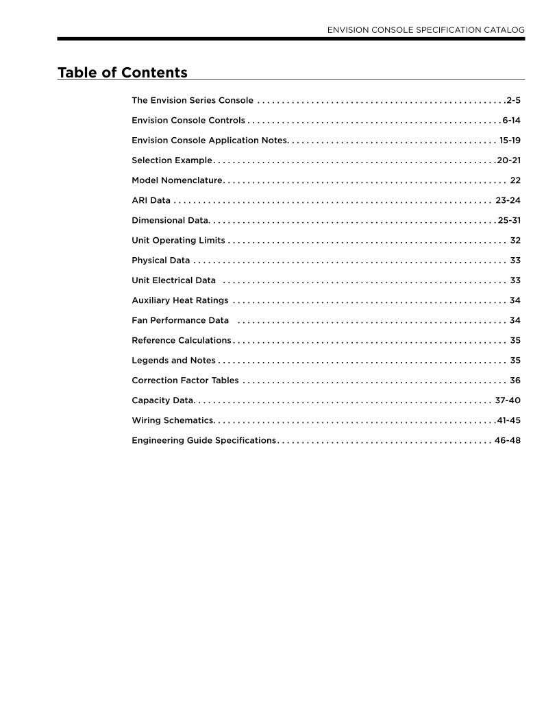
The Envision Series Console . . . . . . . . . . . . . . . . . . . . . . . . . . . . . . . . . . . . . . . . . . . . . . . . . . .2-5
Envision Console Controls . . . . . . . . . . . . . . . . . . . . . . . . . . . . . . . . . . . . . . . . . . . . . . . . . . . . 6-14
Envision Console Application Notes. . . . . . . . . . . . . . . . . . . . . . . . . . . . . . . . . . . . . . . . . . . 15-19
Selection Example. . . . . . . . . . . . . . . . . . . . . . . . . . . . . . . . . . . . . . . . . . . . . . . . . . . . . . . . . .20-21
Model Nomenclature. . . . . . . . . . . . . . . . . . . . . . . . . . . . . . . . . . . . . . . . . . . . . . . . . . . . . . . . . . 22
ARI Data . . . . . . . . . . . . . . . . . . . . . . . . . . . . . . . . . . . . . . . . . . . . . . . . . . . . . . . . . . . . . . . . . 23-24
Dimensional Data. . . . . . . . . . . . . . . . . . . . . . . . . . . . . . . . . . . . . . . . . . . . . . . . . . . . . . . . . . . 25-31
Unit Operating Limits . . . . . . . . . . . . . . . . . . . . . . . . . . . . . . . . . . . . . . . . . . . . . . . . . . . . . . . . . 32
Physical Data . . . . . . . . . . . . . . . . . . . . . . . . . . . . . . . . . . . . . . . . . . . . . . . . . . . . . . . . . . . . . . . . 33
Unit Electrical Data . . . . . . . . . . . . . . . . . . . . . . . . . . . . . . . . . . . . . . . . . . . . . . . . . . . . . . . . . . 33
Auxiliary Heat Ratings . . . . . . . . . . . . . . . . . . . . . . . . . . . . . . . . . . . . . . . . . . . . . . . . . . . . . . . . 34
Fan Performance Data . . . . . . . . . . . . . . . . . . . . . . . . . . . . . . . . . . . . . . . . . . . . . . . . . . . . . . . 34
Reference Calculations . . . . . . . . . . . . . . . . . . . . . . . . . . . . . . . . . . . . . . . . . . . . . . . . . . . . . . . . 35
Legends and Notes . . . . . . . . . . . . . . . . . . . . . . . . . . . . . . . . . . . . . . . . . . . . . . . . . . . . . . . . . . . 35
Correction Factor Tables . . . . . . . . . . . . . . . . . . . . . . . . . . . . . . . . . . . . . . . . . . . . . . . . . . . . . . 36
Capacity Data. . . . . . . . . . . . . . . . . . . . . . . . . . . . . . . . . . . . . . . . . . . . . . . . . . . . . . . . . . . . . 37-40
Wiring Schematics. . . . . . . . . . . . . . . . . . . . . . . . . . . . . . . . . . . . . . . . . . . . . . . . . . . . . . . . . .41-45
Engineering Guide Specifications. . . . . . . . . . . . . . . . . . . . . . . . . . . . . . . . . . . . . . . . . . . . 46-48
2
ENVISION CONSOLE SPECIFICATION CATALOG
The Envision Series ConsoleNearly 25 years ago WaterFurnace led the way by designing and manufacturing watersource heat pumps for use in
geothermal closed loop applications. In 2003 WaterFurnace developed the first R410A watersource heat pump product
line. Now WaterFurnace extends the Envision product line with the efficient Envision Series Console. Higher efficiency
also means less heat rejected and ultimately shorter earth loops. WaterFurnace quality is well known and respected and
is a result of quality engineering and manufacturing in the state of the art Fort Wayne, Indiana plant. The Envision Series
provides:
Highest efficiencies and lowest operating costs.•
Broadest R410A product line.•
Standard or extended range (geothermal) operation.•
Quiet operation.•
Flexible control options.•
WaterFurnace Quality.•
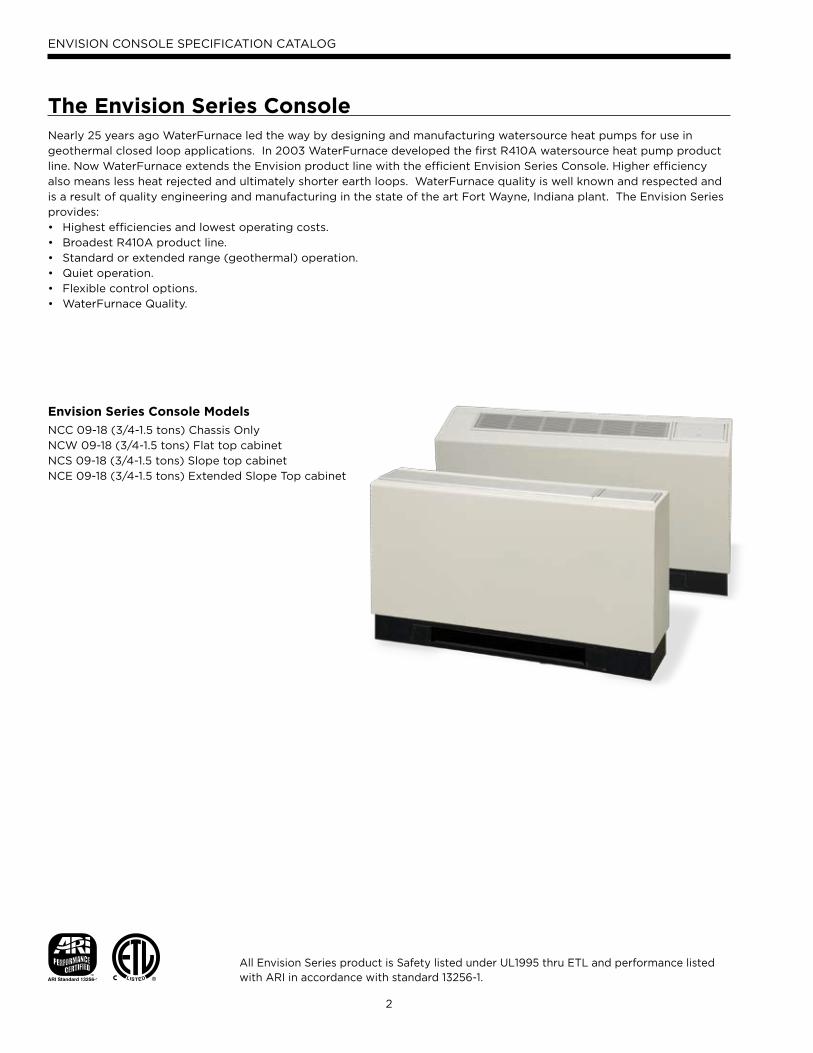
Envision Series Console Models
NCC 09-18 (3/4-1.5 tons) Chassis Only
NCW 09-18 (3/4-1.5 tons) Flat top cabinet
NCS 09-18 (3/4-1.5 tons) Slope top cabinet
NCE 09-18 (3/4-1.5 tons) Extended Slope Top cabinet
All Envision Series product is Safety listed under UL1995 thru ETL and performance listed with ARI in accordance with standard 13256-1.
3
ENVISION CONSOLE SPECIFICATION CATALOG
High Efficiency
Envision Series is the highest efficiency units available.
Large oversized air coils, water to refrigerant heat ex-
changers and rotary compressors provide extremely ef-
ficient operation. This efficiency means the Envision Series
requires less loop than any product on the market. This can
mean significant savings on commercial projects.
Quiet Operation
All Envision Series Console product is ARI 350 sound
rated using third party sound testing. Room Noise Crite-
ria Curves (NC Curve) may be calculated using data from
the ARI 350 ratings giving the engineer total flexibility in
assuring a quiet environment. Please refer to our separate
catalog WaterFurnace Sound Ratings and Performance
Catalog concerning this standard and Envision sound per-
formance data.
Standard FeaturesSlope and Flat top configurations•
Extended cabinet options•
Footprint matches “legacy” products for easy retrofits.•
Attractive rounded corners heavy gauge cabinet.•
Quiet rotary compressors in all models.•
2-dimension refrigerant piping vibration loops to isolate •
the compressor.
All interior cabinet surfaces including the compressor •
compartment are insulated with 1/2˝ [12.7mm] thick
1-1/2lb [681g] density, surface coated, acoustic type •
glass fiber insulation.
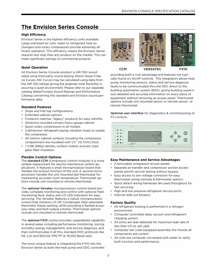
Flexible Control OptionsThe standard CCM (compressor control module) is a more reliable replacement for electro-mechanical control ap-plications. It features a small microprocessor board that handles the lockout function of the unit. A second micro-processor handles the unit mounted dial thermostat for maintaining accurate room temperature. Thermostat op-tions include unit mounted or remote thermostat.
The optional Versatec microprocessor control board pro-vides complete monitoring and control with optional field monitoring fault, status and I/O LED indication for easy servicing. The Versatec features a robust microprocessor control that monitors LP, HP, Condensate, field selectable thermistor freeze sensing, while providing a flexible acces-sory relay and fault output scheme. Thermostat options include unit mounted or remote thermostat.
The optional FX10 control provides unparalleled capability
in several areas including performance monitoring, zoning,
humidity, energy management, and service diagnosis, and
then communicates it all thru standard DDC protocols like
N2, Lon and BACnet (MS/TP @ 19,200 Baud rate).
The most unique feature is integrating the FX10 into the
Envision Series as both the heat pump and DDC controller
providing both a cost advantage and features not typi-
cally found on WLHP controls. This integration allows heat
pump monitoring sensors, status and service diagnosis
faults to be communicated thru the DDC direct to the
building automation system (BAS), giving building supervi-
sors detailed and accurate information on every piece of
equipment without removing an access panel. Thermostat options include unit mounted sensor or remote sensor or
remote thermostat.
Optional user interface for diagnostics & commissioning of
FX controls.
Easy Maintenance and Service Advantages2 removable compressor access panels•
Separate air handler and compressor section access •
panels permit service testing without bypass.
Easy access to low voltage connector for easy •
thermostat wiring (remote & thermostat option).
Quick attach wiring harnesses are used throughout for •
fast servicing.
High and low pressure refrigerant service ports.•
Internal slide out blowers. •
Factory QualityAll refrigerant brazing is performed in a nitrogen •
environment.
Computer controlled deep vacuum and refrigerant •
charging system.
All joints are leak detected for maximum leak rate of •
less than 1/4 oz. per year.
Computer bar code equipped assembly line insures all •
components are correct.
All units are computer run-tested with water to verify •
both function and performance.
The Envision Series Console
VERSATEC FX10CCM
4
ENVISION CONSOLE SPECIFICATION CATALOG
Inside the Envision Series ConsoleRefrigerant
Envision products all feature zero ozone depletion and low
global warming potential refrigerant R410A.
Cabinet
All units are all constructed of corrosion resistant
galvanized sheet metal with white polyester powder
coat paint rated for more than 1000 hours of salt
spray. Refrigerant circuit is designed to allow primary
serviceability from the front. One access panel allows
servicing of the fan motor, blower, and drain pan. Cabinet
is designed to match "industry" foot print for ease of
replacement.
Drain PanAll condensate connections are welded stainless steel
tubes for economical corrosion free connections. Bacteria
resistant stainless steel drain pan is designed to promote
complete drainage and will never rust or corrode.
Complete drainage helps to inhibit bacterial or microbial
growth. Units feature an internally trapped condensate line.
CompressorsHigh efficiency R410A rotary compressors are used on
every model. Rotary compressors (available in 208-230V
& 265V 60Hz Single Phase) provide both the highest
efficiency available and great reliability.
Electrical BoxUnit controls feature quick connect wiring harnesses for
easy servicing. Large 75VA transformer assures adequate
controls power for accessories.
Thermostatic Expansion ValveAll Envision models utilize a balanced port bi-directional
thermostatic expansion valve (TXV) for refrigerant
metering. This allows precise refrigerant flow in a wide
range of entering water variation (20 to 120°F [-7 to 49
°C]) found in geothermal systems.
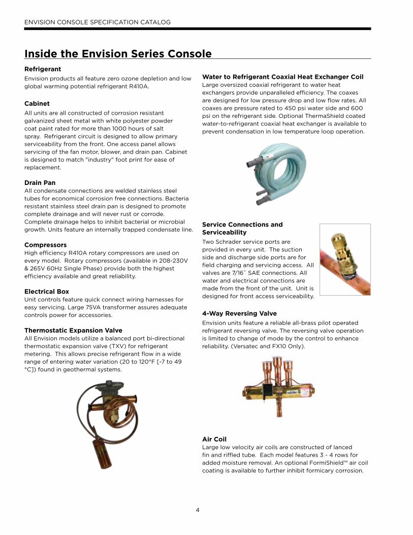
Water to Refrigerant Coaxial Heat Exchanger CoilLarge oversized coaxial refrigerant to water heat
exchangers provide unparalleled efficiency. The coaxes
are designed for low pressure drop and low flow rates. All
coaxes are pressure rated to 450 psi water side and 600
psi on the refrigerant side. Optional ThermaShield coated
water-to-refrigerant coaxial heat exchanger is available to
prevent condensation in low temperature loop operation.
Service Connections and Serviceability
Two Schrader service ports are
provided in every unit. The suction
side and discharge side ports are for
field charging and servicing access. All
valves are 7/16˝ SAE connections. All
water and electrical connections are
made from the front of the unit. Unit is
designed for front access serviceability.
4-Way Reversing Valve
Envision units feature a reliable all-brass pilot operated
refrigerant reversing valve. The reversing valve operation
is limited to change of mode by the control to enhance
reliability. (Versatec and FX10 Only).
Air CoilLarge low velocity air coils are constructed of lanced
fin and riffled tube. Each model features 3 - 4 rows for
added moisture removal. An optional FormiShield™ air coil
coating is available to further inhibit formicary corrosion.

5
ENVISION CONSOLE SPECIFICATION CATALOG
Blower Motor and Housing
High efficiency low rpm galvanized direct drive blowers
featuring 2 speed permanently split capacitor (PSC) motor.
All PSC motors have speed selection switch on the control
cover for easy speed change. All motors are vibration
isolated to reduce noise.
Inside the Envision Series Console
6
ENVISION CONSOLE SPECIFICATION CATALOG
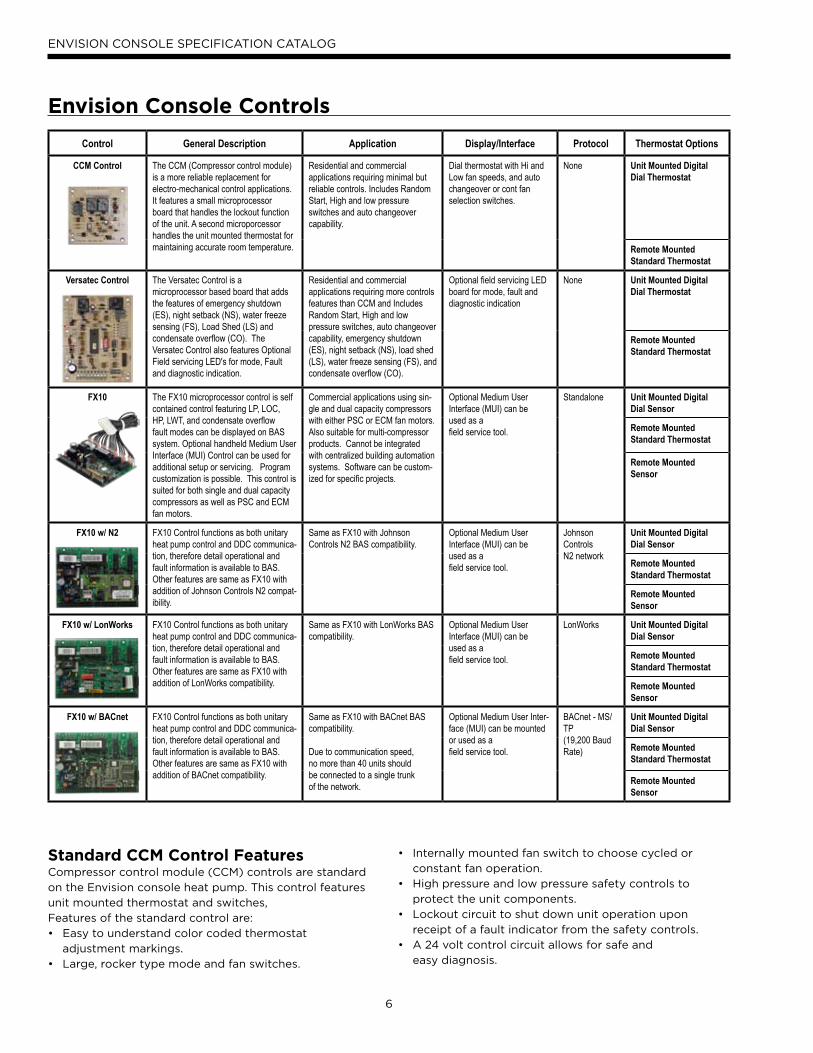
Control General Description Application Display/Interface Protocol Thermostat Options
CCM Control The CCM (Compressor control module) is a more reliable replacement for electro-mechanical control applications. It features a small microprocessor board that handles the lockout function of the unit. A second microporcessor handles the unit mounted thermostat for maintaining accurate room temperature.
Residential and commercial applications requiring minimal but reliable controls. Includes Random Start, High and low pressure switches and auto changeover capability.
Dial thermostat with Hi and Low fan speeds, and auto changeover or cont fan selection switches.
None Unit Mounted Digital Dial Thermostat
Remote Mounted Standard Thermostat
Versatec Control The Versatec Control is a microprocessor based board that adds the features of emergency shutdown (ES), night setback (NS), water freeze sensing (FS), Load Shed (LS) and condensate overflow (CO). The Versatec Control also features Optional Field servicing LED's for mode, Fault and diagnostic indication.
Residential and commercial applications requiring more controls features than CCM and Includes Random Start, High and low pressure switches, auto changeover capability, emergency shutdown (ES), night setback (NS), load shed (LS), water freeze sensing (FS), and condensate overflow (CO).
Optional field servicing LED board for mode, fault and diagnostic indication
None Unit Mounted Digital Dial Thermostat
Remote Mounted Standard Thermostat
FX10 The FX10 microprocessor control is self contained control featuring LP, LOC, HP, LWT, and condensate overflow fault modes can be displayed on BAS system. Optional handheld Medium User Interface (MUI) Control can be used for additional setup or servicing. Program customization is possible. This control is suited for both single and dual capacity compressors as well as PSC and ECM fan motors.
Commercial applications using sin-gle and dual capacity compressors with either PSC or ECM fan motors. Also suitable for multi-compressor products. Cannot be integrated with centralized building automation systems. Software can be custom-ized for specific projects.
Optional Medium User Interface (MUI) can be used as afield service tool.
Standalone Unit Mounted Digital Dial Sensor
Remote Mounted Standard Thermostat
Remote Mounted Sensor
FX10 w/ N2 FX10 Control functions as both unitary heat pump control and DDC communica-tion, therefore detail operational and fault information is available to BAS. Other features are same as FX10 with addition of Johnson Controls N2 compat-ibility.
Same as FX10 with Johnson Controls N2 BAS compatibility.
Optional Medium User Interface (MUI) can be used as afield service tool.
JohnsonControlsN2 network
Unit Mounted Digital Dial Sensor
Remote Mounted Standard Thermostat
Remote Mounted Sensor
FX10 w/ LonWorks FX10 Control functions as both unitary heat pump control and DDC communica-tion, therefore detail operational and fault information is available to BAS. Other features are same as FX10 with addition of LonWorks compatibility.
Same as FX10 with LonWorks BAS compatibility.
Optional Medium User Interface (MUI) can be used as afield service tool.
LonWorks Unit Mounted Digital Dial Sensor
Remote Mounted Standard Thermostat
Remote Mounted Sensor
FX10 w/ BACnet FX10 Control functions as both unitary heat pump control and DDC communica-tion, therefore detail operational and fault information is available to BAS. Other features are same as FX10 with addition of BACnet compatibility.
Same as FX10 with BACnet BAS compatibility.
Due to communication speed,no more than 40 units shouldbe connected to a single trunkof the network.
Optional Medium User Inter-face (MUI) can be mounted or used as afield service tool.
BACnet - MS/TP(19,200 Baud Rate)
Unit Mounted Digital Dial Sensor
Remote Mounted Standard Thermostat
Remote Mounted Sensor
Standard CCM Control FeaturesCompressor control module (CCM) controls are standard
on the Envision console heat pump. This control features
unit mounted thermostat and switches,
Features of the standard control are:
Easy to understand color coded thermostat •
adjustment markings.
Large, rocker type mode and fan switches.•
Internally mounted fan switch to choose cycled or •
constant fan operation.
High pressure and low pressure safety controls to •
protect the unit components.
Lockout circuit to shut down unit operation upon •
receipt of a fault indicator from the safety controls.
A 24 volt control circuit allows for safe and •
easy diagnosis.
Envision Console Controls
7
ENVISION CONSOLE SPECIFICATION CATALOG
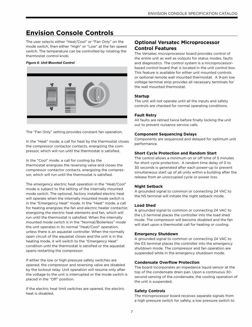
Figure 6: Unit Mounted Control
The user selects either “Heat/Cool” or “Fan Only” on the
mode switch, then either “High” or “Low” at the fan speed
switch. The temperature can be controlled by rotating the
thermostat control knob.
The “Fan Only” setting provides constant fan operation.
In the “Heat” mode, a call for heat by the thermostat closes
the compressor contactor contacts, energizing the com-
pressor, which will run until the thermostat is satisfied.
In the “Cool” mode, a call for cooling by the
thermostat energizes the reversing valve and closes the
compressor contactor contacts, energizing the compres-
sor, which will run until the thermostat is satisfied.
The emergency electric heat operation in the “Heat/Cool”
mode is subject to the setting of the internally mounted
mode switch. The optional, factory installed electric heat
will operate when the internally mounted mode switch is
in the “Emergency Heat” mode. In the “Heat” mode, a call
for heating energizes the fan and electric heater contactor,
energizing the electric heat elements and fan, which will
run until the thermostat is satisfied. When the internally
mounted mode switch is in the “Normal/Boilerless” mode
the unit operates in its normal “Heat/Cool” operation,
unless there is an aquastat controller. When the normally
open circuit of the aquastat closes and the unit is in the
heating mode, it will switch to the “Emergency Heat”
condition until the thermostat is satisfied or the aquastat
opens restarting the compressor.
If either the low or high pressure safety switches are
opened, the compressor and reversing valve are disabled
by the lockout relay. Unit operation will resume only after
the voltage to the unit is interrupted or the mode switch is
placed in the “Off” position.
If the electric heat limit switches are opened, the electric
heat is disabled.
Optional Versatec Microprocessor Control FeaturesThe Versatec microprocessor board provides control of
the entire unit as well as outputs for status modes, faults
and diagnostics. The control system is a microprocessor-
based control board that is located in the unit control box.
This feature is available for either unit mounted controls
or optional remote wall mounted thermostat. A 9-pin low
voltage terminal strip provides all necessary terminals for
the wall mounted thermostat.
StartupThe unit will not operate until all the inputs and safety
controls are checked for normal operating conditions.
Fault RetryAll faults are retried twice before finally locking the unit
out to prevent nuisance service calls.
Component Sequencing DelaysComponents are sequenced and delayed for optimum unit
performance.
Short Cycle Protection and Random StartThe control allows a minimum on or off time of 5 minutes
for short cycle protection. A random time delay of 0 to
30 seconds is generated after each power-up to prevent
simultaneous start up of all units within a building after the
release from an unoccupied cycle or power loss.
Night SetbackA grounded signal to common or connecting 24 VAC to
the NS terminal will initiate the night setback mode.
Load ShedA grounded signal to common or connecting 24 VAC to
the LS terminal places the controller into the load shed
mode. The compressor will become disabled and the fan
will start upon a thermostat call for heating or cooling.
Emergency ShutdownA grounded signal to common or connecting 24 VAC to
the ES terminal places the controller into the emergency
shutdown mode. The compressor and fan operation are
suspended while in the emergency shutdown mode.
Condensate Overflow ProtectionThe board incorporates an impedance liquid sensor at the
top of the condensate drain pan. Upon a continuous 30-
second sensing of the condensate, the cooling operation of
the unit is suspended.
Safety ControlsThe microprocessor board receives separate signals from
a high pressure switch for safety, a low pressure switch to
Envision Console Controls
8
ENVISION CONSOLE SPECIFICATION CATALOG
Envision Console Controls
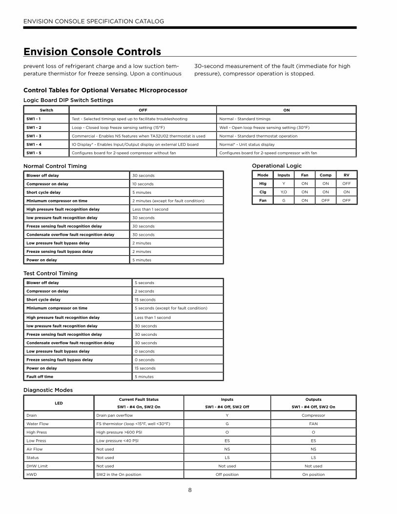
Mode Inputs Fan Comp RV
Htg Y ON ON OFF
Clg Y,O ON ON ON
Fan G ON OFF OFF
Switch OFF ON
SW1 - 1 Test - Selected timings sped up to facilitate troubleshooting Normal - Standard timings
SW1 - 2 Loop - Closed loop freeze sensing setting (15°F) Well - Open loop freeze sensing setting (30°F)
SW1 - 3 Commercial - Enables NS features when TA32U02 thermostat is used Normal - Standard thermostat operation
SW1 - 4 IO Display* - Enables Input/Output display on external LED board Normal* - Unit status display
SW1 - 5 Configures board for 2-speed compressor without fan Configures board for 2-speed compressor with fan
Logic Board DIP Switch Settings
Blower off delay 30 seconds
Compressor on delay 10 seconds
Short cycle delay 5 minutes
Miniumum compressor on time 2 minutes (except for fault condition)
High pressure fault recognition delay Less than 1 second
low pressure fault recognition delay 30 seconds
Freeze sensing fault recognition delay 30 seconds
Condensate overflow fault recognition delay 30 seconds
Low pressure fault bypass delay 2 minutes
Freeze sensing fault bypass delay 2 minutes
Power on delay 5 minutes
Normal Control Timing Operational Logic
Blower off delay 5 seconds
Compressor on delay 2 seconds
Short cycle delay 15 seconds
Miniumum compressor on time 5 seconds (except for fault condition)
High pressure fault recognition delay Less than 1 second
low pressure fault recognition delay 30 seconds
Freeze sensing fault recognition delay 30 seconds
Condensate overflow fault recognition delay 30 seconds
Low pressure fault bypass delay 0 seconds
Freeze sensing fault bypass delay 0 seconds
Power on delay 15 seconds
Fault off time 5 minutes
Test Control Timing
LEDCurrent Fault Status
SW1 - #4 On, SW2 On
Inputs
SW1 - #4 Off, SW2 Off
Outputs
SW1 - #4 Off, SW2 On
Drain Drain pan overflow Y Compressor
Water Flow FS thermistor (loop <15°F, well <30°F) G FAN
High Press High pressure >600 PSI O O
Low Press Low pressure <40 PSI ES ES
Air Flow Not used NS NS
Status Not used LS LS
DHW Limit Not used Not used Not used
HWD SW2 in the On position Off position On position
Diagnostic Modes
prevent loss of refrigerant charge and a low suction tem-
perature thermistor for freeze sensing. Upon a continuous
30-second measurement of the fault (immediate for high
pressure), compressor operation is stopped.
Control Tables for Optional Versatec Microprocessor
9
ENVISION CONSOLE SPECIFICATION CATALOG
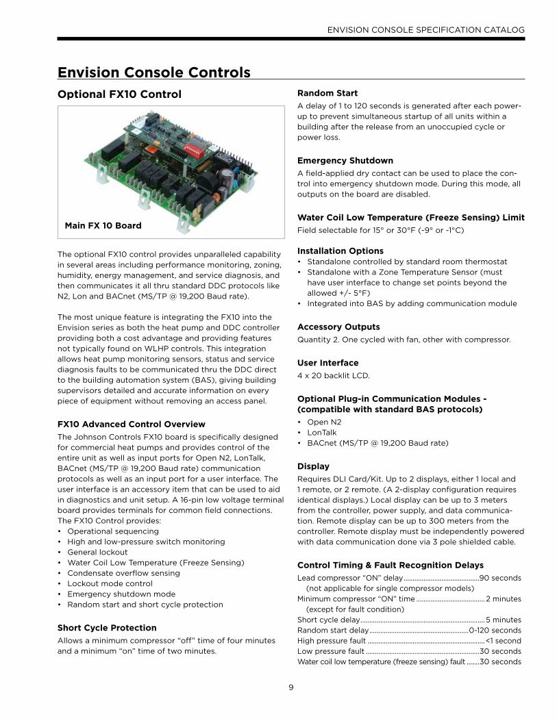
Optional FX10 Control
The optional FX10 control provides unparalleled capability
in several areas including performance monitoring, zoning,
humidity, energy management, and service diagnosis, and
then communicates it all thru standard DDC protocols like
N2, Lon and BACnet (MS/TP @ 19,200 Baud rate).
The most unique feature is integrating the FX10 into the
Envision series as both the heat pump and DDC controller
providing both a cost advantage and providing features
not typically found on WLHP controls. This integration
allows heat pump monitoring sensors, status and service
diagnosis faults to be communicated thru the DDC direct
to the building automation system (BAS), giving building
supervisors detailed and accurate information on every
piece of equipment without removing an access panel.
FX10 Advanced Control Overview
The Johnson Controls FX10 board is specifically designed
for commercial heat pumps and provides control of the
entire unit as well as input ports for Open N2, LonTalk,
BACnet (MS/TP @ 19,200 Baud rate) communication
protocols as well as an input port for a user interface. The
user interface is an accessory item that can be used to aid
in diagnostics and unit setup. A 16-pin low voltage terminal
board provides terminals for common field connections.
The FX10 Control provides:
Operational sequencing•
High and low-pressure switch monitoring •
General lockout•
Water Coil Low Temperature (Freeze Sensing) •
Condensate overflow sensing •
Lockout mode control •
Emergency shutdown mode •
Random start and short cycle protection•
Short Cycle Protection
Allows a minimum compressor “off” time of four minutes
and a minimum “on” time of two minutes.
Random Start
A delay of 1 to 120 seconds is generated after each power-
up to prevent simultaneous startup of all units within a
building after the release from an unoccupied cycle or
power loss.
Emergency Shutdown
A field-applied dry contact can be used to place the con-
trol into emergency shutdown mode. During this mode, all
outputs on the board are disabled.
Water Coil Low Temperature (Freeze Sensing) Limit
Field selectable for 15° or 30°F (-9° or -1°C)
Installation Options
Standalone controlled by standard room thermostat•
Standalone with a Zone Temperature Sensor (must •
have user interface to change set points beyond the
allowed +/- 5°F)
Integrated into BAS by adding communication module•
Accessory Outputs
Quantity 2. One cycled with fan, other with compressor.
User Interface
4 x 20 backlit LCD.
Optional Plug-in Communication Modules - (compatible with standard BAS protocols)
Open N2•
LonTalk•
BACnet (MS/TP @ 19,200 Baud rate)•
Display
Requires DLI Card/Kit. Up to 2 displays, either 1 local and
1 remote, or 2 remote. (A 2-display configuration requires
identical displays.) Local display can be up to 3 meters
from the controller, power supply, and data communica-
tion. Remote display can be up to 300 meters from the
controller. Remote display must be independently powered
with data communication done via 3 pole shielded cable.
Control Timing & Fault Recognition Delays
Lead compressor “ON” delay ..........................................90 seconds
(not applicable for single compressor models)
Minimum compressor “ON” time ...................................... 2 minutes
(except for fault condition)
Short cycle delay ..................................................................... 5 minutes
Random start delay .......................................................0-120 seconds
High pressure fault .................................................................<1 second
Low pressure fault ...............................................................30 seconds
Water coil low temperature (freeze sensing) fault .......30 seconds
Envision Console Controls
Main FX 10 Board
10
ENVISION CONSOLE SPECIFICATION CATALOG
Condensate overflow fault ...............................................30 seconds
Low pressure fault bypass ................................................... 2 minutes
Water coil low temperature (freeze sensing)
fault bypass .......................................................................... 2 minutes
Notes: Refer to Submittal Data SD1981, Application Guide AGFX10, or BACnet Protocol Implementation Conformance Statement for more information.
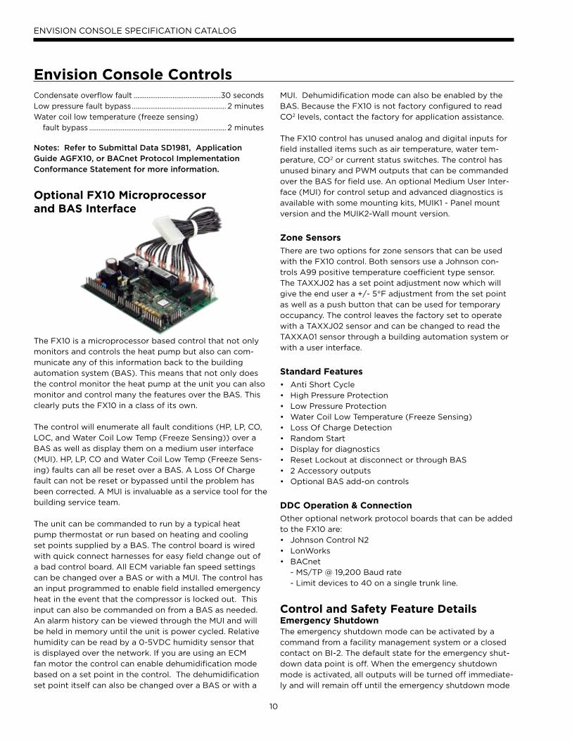
Optional FX10 Microprocessor and BAS Interface
The FX10 is a microprocessor based control that not only
monitors and controls the heat pump but also can com-
municate any of this information back to the building
automation system (BAS). This means that not only does
the control monitor the heat pump at the unit you can also
monitor and control many the features over the BAS. This
clearly puts the FX10 in a class of its own.
The control will enumerate all fault conditions (HP, LP, CO,
LOC, and Water Coil Low Temp (Freeze Sensing)) over a
BAS as well as display them on a medium user interface
(MUI). HP, LP, CO and Water Coil Low Temp (Freeze Sens-
ing) faults can all be reset over a BAS. A Loss Of Charge
fault can not be reset or bypassed until the problem has
been corrected. A MUI is invaluable as a service tool for the
building service team.
The unit can be commanded to run by a typical heat
pump thermostat or run based on heating and cooling
set points supplied by a BAS. The control board is wired
with quick connect harnesses for easy field change out of
a bad control board. All ECM variable fan speed settings
can be changed over a BAS or with a MUI. The control has
an input programmed to enable field installed emergency
heat in the event that the compressor is locked out. This
input can also be commanded on from a BAS as needed.
An alarm history can be viewed through the MUI and will
be held in memory until the unit is power cycled. Relative
humidity can be read by a 0-5VDC humidity sensor that
is displayed over the network. If you are using an ECM
fan motor the control can enable dehumidification mode
based on a set point in the control. The dehumidification
set point itself can also be changed over a BAS or with a
MUI. Dehumidification mode can also be enabled by the
BAS. Because the FX10 is not factory configured to read
CO2 levels, contact the factory for application assistance.
The FX10 control has unused analog and digital inputs for
field installed items such as air temperature, water tem-
perature, CO2 or current status switches. The control has
unused binary and PWM outputs that can be commanded
over the BAS for field use. An optional Medium User Inter-
face (MUI) for control setup and advanced diagnostics is
available with some mounting kits, MUIK1 - Panel mount
version and the MUIK2-Wall mount version.
Zone Sensors
There are two options for zone sensors that can be used
with the FX10 control. Both sensors use a Johnson con-
trols A99 positive temperature coefficient type sensor.
The TAXXJ02 has a set point adjustment now which will
give the end user a +/- 5°F adjustment from the set point
as well as a push button that can be used for temporary
occupancy. The control leaves the factory set to operate
with a TAXXJ02 sensor and can be changed to read the
TAXXA01 sensor through a building automation system or
with a user interface.
Standard Features
Anti Short Cycle•
High Pressure Protection•
Low Pressure Protection•
Water Coil Low Temperature (Freeze Sensing)•
Loss Of Charge Detection•
Random Start•
Display for diagnostics•
Reset Lockout at disconnect or through BAS•
2 Accessory outputs•
Optional BAS add-on controls•
DDC Operation & Connection
Other optional network protocol boards that can be added
to the FX10 are:
Johnson Control N2•
LonWorks•
BACnet •
- MS/TP @ 19,200 Baud rate
- Limit devices to 40 on a single trunk line.
Control and Safety Feature Details Emergency ShutdownThe emergency shutdown mode can be activated by a
command from a facility management system or a closed
contact on BI-2. The default state for the emergency shut-
down data point is off. When the emergency shutdown
mode is activated, all outputs will be turned off immediate-
ly and will remain off until the emergency shutdown mode
Envision Console Controls
11
ENVISION CONSOLE SPECIFICATION CATALOG
is de-activated. The first time the compressor starts after
the emergency shutdown mode has been de-activated,
there will be a random start delay present.
Lockout ModeLockout mode can be activated by any of the following
fault signals: refrigerant system high pressure, refrigerant
system low pressure, water coil low temperature (freeze
sensing), and condensate overflow. When any valid fault
signal remains continuously active for the length of its rec-
ognition delay, the controller will go into fault retry mode,
which will turn off the compressor. After the Compressor
short cycle delay, the compressor will attempt to operate
once again. If three consecutive faults occur in 60 minutes
during a single heating or cooling demand, the unit will go
into lockout mode, turning off the compressor, enabling
the alarm output, and setting the fan back to low speed
operation until the controller is reset. If the control faults
due to the low pressure input (BI-3) being open during
the pre-compressor startup check, the control will go into
lockout mode immediately, disabling the compressor from
starting and enabling the alarm output (BO-6). The lockout
condition can be reset by powering down the controller, by
a command from the BAS, or by the holding the ESC and
Return keys on the MUI for 5 seconds.
Water Coil Low Temp (Freeze Sensing) Limit (AI-5)The water coil low temperature (freeze sensing) limit sen-
sor will monitor the liquid refrigerant temperature enter-
ing the water coil in the heating mode. If the temperature
drops below the water coil low temperature (freeze sens-
ing) limit trip point for the recognition delay period, the
condition will be recognized as a fault. The water coil low
temperature (freeze sensing) limit trip point will be factory
set for 30°F and will be field selectable for 15°F by remov-
ing a jumper wire on BI-5. The water coil low temperature
(freeze sensing) limit fault condition will be bypassed 2
minutes at normal compressor startup, to allow the refrig-
eration circuit to stabilize. If the water coil low temperature
(freeze sensing) limit sensor becomes unreliable at any
time compressor operation will immediately be suspended
until the problem is corrected. This should be displayed
as an alarm on the BAS and the MUI. This alarm will be
reported a “Water Low Temp Limit” fault.
High Pressure (BI-11)The high-pressure switch shall be a normally closed (NC)
switch that monitors the systems refrigerant pressure. If
the input senses the high-pressure switch is open it must
disable the compressor output immediately and count the
fault. The compressor minimum on time does not apply if
the high-pressure switch opens. The compressor will not
restart until the compressor short cycle time delay has
been satisfied.
Low Pressure (BI-3)The low-pressure switch shall be a normally closed (NC)
switch that monitors the systems refrigerant pressure. The
input shall be checked 15 seconds before compressor start
up to be sure the pressure switch is closed and then ignored
for the first 2 minutes after the compressor output (BO-2) is
enabled. If the switch is open continuously for (30) seconds
during compressor operation the compressor output (BO-2)
will be disabled. The compressor will not restart until the
compressor short cycle time delay has been satisfied.
Condensate OverflowThe condensate overflow sensing circuit will monitor the
condensate level as a resistance input to AI-3. If the con-
densate water level rises resulting in the input resistance
rising above the set point for the recognition delay period,
the condition will be recognized as a fault. The condensate
will be subjected to a (30) second lockout delay which
requires that the fault be sensed for a continuous (30)
seconds before suspending unit operation.
Alarm Output (BO-6)The alarm output will be enabled when the control is in the
lockout mode and will be disabled when the lockout is reset.
Test ModeRaising the zone temperature input (AI-1) reading to
180–220°F or by holding the ESC and down arrow keys on
the MUI for 5 seconds will put the control into test mode.
In test mode the random start delay and the compressor
fixed on delay time will both be shortened to 5 seconds
and the reversing valve will be allowed to cycle with out
shutting down the compressor. If an MUI is connected to
the control LED 8 will flash and the words “Test Mode En-
abled” will be shown on the LCD display when the control
is in test mode. Test mode will be disabled after a power
cycle, 30 minute timeout, or by holding the ESC and Up
arrow keys on the MUI.
Sequence of OperationPower Fail RestartWhen the controller is first powered up, the outputs will be
disabled for a random start delay. The delay is provided
to prevent simultaneous starting of multiple heat pumps.
Once the timer expires, the controller will operate normally.
Random Start Delay
This delay will be used after every power failure, as well as
the first time the compressor is started after the control
exits the unoccupied mode or the emergency shutdown
mode. The delay should not be less than 1 second and not
longer than 120 seconds. If the control is in test mode the
random start delay will be shortened to 5 seconds.
Envision Console Controls
12
ENVISION CONSOLE SPECIFICATION CATALOG
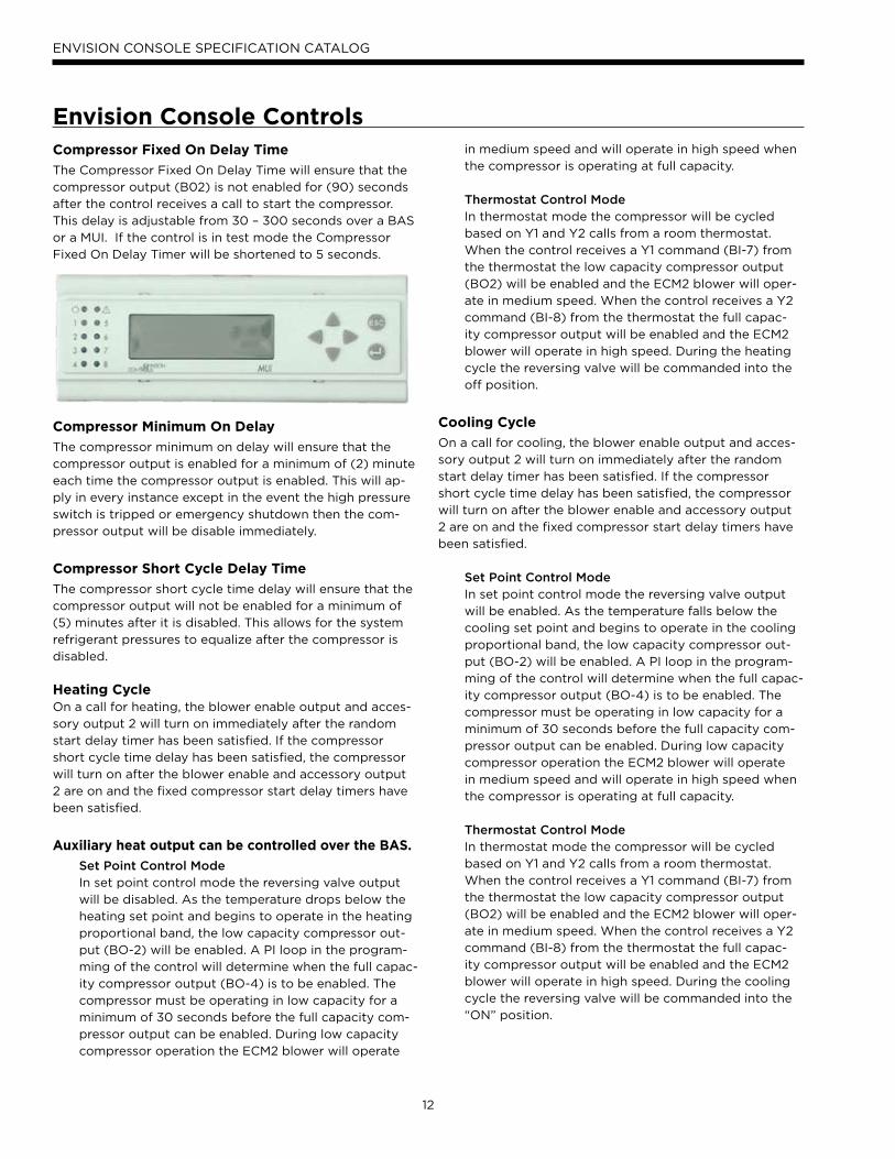
Compressor Fixed On Delay Time
The Compressor Fixed On Delay Time will ensure that the
compressor output (B02) is not enabled for (90) seconds
after the control receives a call to start the compressor.
This delay is adjustable from 30 – 300 seconds over a BAS
or a MUI. If the control is in test mode the Compressor
Fixed On Delay Timer will be shortened to 5 seconds.
Compressor Minimum On Delay
The compressor minimum on delay will ensure that the
compressor output is enabled for a minimum of (2) minute
each time the compressor output is enabled. This will ap-
ply in every instance except in the event the high pressure
switch is tripped or emergency shutdown then the com-
pressor output will be disable immediately.
Compressor Short Cycle Delay Time
The compressor short cycle time delay will ensure that the
compressor output will not be enabled for a minimum of
(5) minutes after it is disabled. This allows for the system
refrigerant pressures to equalize after the compressor is
disabled.
Heating CycleOn a call for heating, the blower enable output and acces-
sory output 2 will turn on immediately after the random
start delay timer has been satisfied. If the compressor
short cycle time delay has been satisfied, the compressor
will turn on after the blower enable and accessory output
2 are on and the fixed compressor start delay timers have
been satisfied.
Auxiliary heat output can be controlled over the BAS.
Set Point Control ModeIn set point control mode the reversing valve output
will be disabled. As the temperature drops below the
heating set point and begins to operate in the heating
proportional band, the low capacity compressor out-
put (BO-2) will be enabled. A PI loop in the program-
ming of the control will determine when the full capac-
ity compressor output (BO-4) is to be enabled. The
compressor must be operating in low capacity for a
minimum of 30 seconds before the full capacity com-
pressor output can be enabled. During low capacity
compressor operation the ECM2 blower will operate
in medium speed and will operate in high speed when
the compressor is operating at full capacity.
Thermostat Control ModeIn thermostat mode the compressor will be cycled
based on Y1 and Y2 calls from a room thermostat.
When the control receives a Y1 command (BI-7) from
the thermostat the low capacity compressor output
(BO2) will be enabled and the ECM2 blower will oper-
ate in medium speed. When the control receives a Y2
command (BI-8) from the thermostat the full capac-
ity compressor output will be enabled and the ECM2
blower will operate in high speed. During the heating
cycle the reversing valve will be commanded into the
off position.
Cooling Cycle
On a call for cooling, the blower enable output and acces-
sory output 2 will turn on immediately after the random
start delay timer has been satisfied. If the compressor
short cycle time delay has been satisfied, the compressor
will turn on after the blower enable and accessory output
2 are on and the fixed compressor start delay timers have
been satisfied.
Set Point Control ModeIn set point control mode the reversing valve output
will be enabled. As the temperature falls below the
cooling set point and begins to operate in the cooling
proportional band, the low capacity compressor out-
put (BO-2) will be enabled. A PI loop in the program-
ming of the control will determine when the full capac-
ity compressor output (BO-4) is to be enabled. The
compressor must be operating in low capacity for a
minimum of 30 seconds before the full capacity com-
pressor output can be enabled. During low capacity
compressor operation the ECM2 blower will operate
in medium speed and will operate in high speed when
the compressor is operating at full capacity.
Thermostat Control ModeIn thermostat mode the compressor will be cycled
based on Y1 and Y2 calls from a room thermostat.
When the control receives a Y1 command (BI-7) from
the thermostat the low capacity compressor output
(BO2) will be enabled and the ECM2 blower will oper-
ate in medium speed. When the control receives a Y2
command (BI-8) from the thermostat the full capac-
ity compressor output will be enabled and the ECM2
blower will operate in high speed. During the cooling
cycle the reversing valve will be commanded into the
“ON” position.
Envision Console Controls
13
ENVISION CONSOLE SPECIFICATION CATALOG
ECM2 Blower Operation
Fan speeds will be selected through the user interface or
the facility management system. There will be a total of 12
speeds selectable with only three being selected at any
one time. The lowest numbered speed selection set to ON
will select the low-speed fan setting, the middle selection
set to ON will select the medium-speed fan setting and
the highest selection set to ON will select the high-speed
fan setting. If all selections are set to OFF the software
shall select speed setting 10 for low-speed, 11 for medium-
speed, and will select speed setting 12 for high speed. If
only one selection is set to ON, that selection will set the
low-speed fan setting, the medium-speed setting will be 11,
and the high-speed setting will be speed 12. The maximum
low-speed setting will be speed 10 and the minimum high-
speed setting will be speed 3. In addition there is a low limit
setting in the software to prevent the ECM2 fan speed from
being set below acceptable limits for each unit size.
ECM2 Fan air flow “Soft Switch Settings”
A set of 12 “soft switches” accessible through the user
interface or building automation system are used to select
the three fan speed settings for the ECM2 fan motor.
The 12 soft switches work in exactly the same way as the
hardware switches used on the Premier control (Refer to
Fan Performance Data - ECM2 Motor for proper settings).
No more than three soft switches may be set to the “ON”
position. The first “ON” switch (the lowest number switch)
determines the “low speed fan” setting. The second de-
termines the “medium speed fan” setting, and the third
determines the “high speed fan” setting.
Emergency Heat/Network Enabled Output (BO5)
This output is set from the factory to enable/disable
emergency heat. If a problem occurs with the unit result-
ing in the compressor being locked out in heating mode,
the control will automatically enable this output to turn
on field installed electric heat. This output is interlocked
with the fan proving input BI-6 (Fan proving sensors must
be field supplied and installed). BI-6 must be connected
to PB2 position 3 (see unit schematic) in the field if no fan
proving sensor is desired. There is a configurable parame-
ter available through a BAS network that must be enabled
if this output is to be commanded over the BAS network.
MUI Alarm History Reporting
If a fault occurs the fault will be recorded in history for
display on the medium user interface in the History Menu.
Each fault type will be displayed in the history menu with
a number between 0 and 3. A reading of 3+ will mean
that fault has occurred more than three times in the past.
The history menu can be cleared with a power cycle only.
Alarm date and time are not included in the history.
Inputs & Outputs Configuration Field Selectable Options
Water Coil Low Temp (Freeze Sensing) Limit Set Point (BI-5)The water coil low temperature (freeze sensing) limit set
point input allows you to adjust the water coil low tem-
perature (freeze sensing) limit set point (AI-5). When the
jumper is installed on BI-5 (Wire #24) the water coil low
temperature (freeze sensing) limit set point is factory set
for 30°F. When the jumper on BI-5 (Wire #24) is removed
the water coil low temperature (freeze sensing) limit set
point will be 15°F.
Accessory Outputs (BO-7 and BO-8)Accessory Output 1 will be energized 90 seconds prior to
the compressor output being energized. Accessory Output
2 will be energized with the fan output (BO-1). When the
corresponding compressor output is turned off the acces-
sory output will be deactivated immediately. These outputs
are selectable for normally open or normally closed opera-
tion through the Medium User interface or through the
Building Automation System.
Envision Console Controls
14
ENVISION CONSOLE SPECIFICATION CATALOG
Control AccessoriesZone Sensors
TAXXJ02 Room Command Module•
TAXXA01 LCD Room Command Module•
A99 Sensor•
MUI (LCD User interface) for diagnosticsand commissioning.
MUIK1 - Panel Mount, Portable•
MUIK2 - Wall Mount•
Envision Console Controls
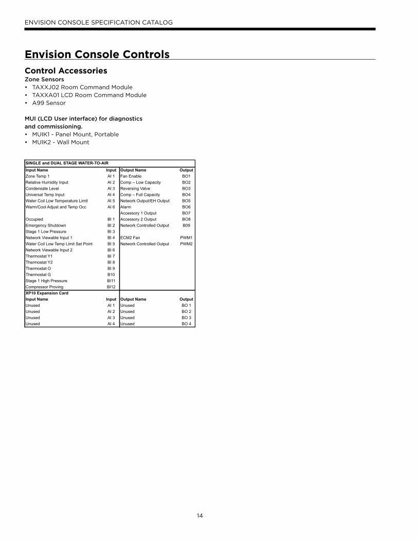
Input Name Input Output Name OutputZone Temp 1 AI 1 Fan Enable BO1Relative Humidity Input AI 2 Comp – Low Capacity BO2Condensate Level AI 3 Reversing Valve BO3Universal Temp Input AI 4 Comp – Full Capacity BO4Water Coil Low Temperature Limit AI 5 Network Output/EH Output BO5Warm/Cool Adjust and Temp Occ AI 6 Alarm BO6
Accessory 1 Output BO7Occupied BI 1 Accessory 2 Output BO8Emergency Shutdown BI 2 Network Controlled Output B09Stage 1 Low Pressure BI 3Network Viewable Input 1 BI 4 ECM2 Fan PWM1Water Coil Low Temp Limit Set Point BI 5 Network Controlled Output PWM2Network Viewable Input 2 BI 6Thermostat Y1 BI 7Thermostat Y2 BI 8Thermostat O BI 9Thermostat G B10Stage 1 High Pressure BI11Compressor Proving BI12XP10 Expansion CardInput Name Input Output Name OutputUnused AI 1 Unused BO 1Unused AI 2 Unused BO 2Unused AI 3 Unused BO 3Unused AI 4 Unused BO 4
SINGLE and DUAL STAGE WATER-TO-AIR
15
ENVISION CONSOLE SPECIFICATION CATALOG
The Closed Loop Heat Pump Concept
The basic principle of a water source heat pump is the
transfer of heat into water from the space during cooling,
or the transfer of heat from water into the space during
heating. Extremely high levels of energy efficiency are
achieved as electricity is used only to move heat, not to
produce it. Using a typical WaterFurnace Envision Series,
one unit of electricity will move four to five units of heat.
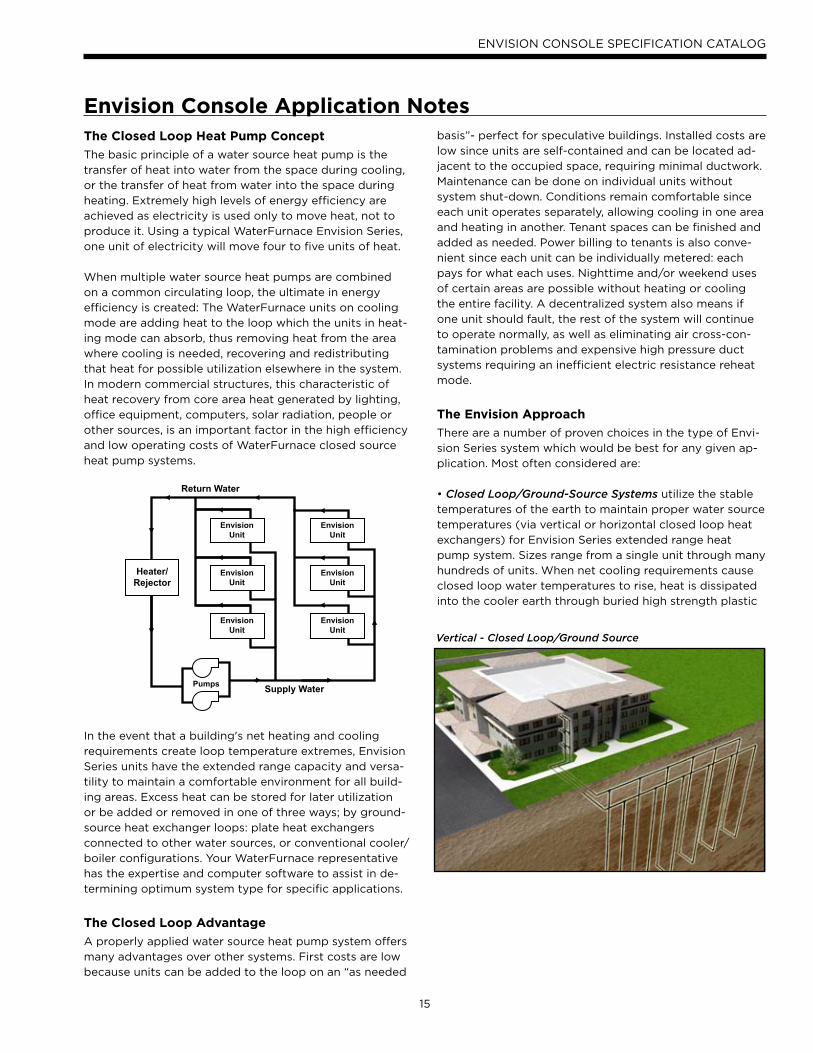
When multiple water source heat pumps are combined
on a common circulating loop, the ultimate in energy
efficiency is created: The WaterFurnace units on cooling
mode are adding heat to the loop which the units in heat-
ing mode can absorb, thus removing heat from the area
where cooling is needed, recovering and redistributing
that heat for possible utilization elsewhere in the system.
In modern commercial structures, this characteristic of
heat recovery from core area heat generated by lighting,
office equipment, computers, solar radiation, people or
other sources, is an important factor in the high efficiency
and low operating costs of WaterFurnace closed source
heat pump systems.
In the event that a building's net heating and cooling
requirements create loop temperature extremes, Envision
Series units have the extended range capacity and versa-
tility to maintain a comfortable environment for all build-
ing areas. Excess heat can be stored for later utilization
or be added or removed in one of three ways; by ground-
source heat exchanger loops: plate heat exchangers
connected to other water sources, or conventional cooler/
boiler configurations. Your WaterFurnace representative
has the expertise and computer software to assist in de-
termining optimum system type for specific applications.
The Closed Loop Advantage
A properly applied water source heat pump system offers
many advantages over other systems. First costs are low
because units can be added to the loop on an “as needed
basis”- perfect for speculative buildings. Installed costs are
low since units are self-contained and can be located ad-
jacent to the occupied space, requiring minimal ductwork.
Maintenance can be done on individual units without
system shut-down. Conditions remain comfortable since
each unit operates separately, allowing cooling in one area
and heating in another. Tenant spaces can be finished and
added as needed. Power billing to tenants is also conve-
nient since each unit can be individually metered: each
pays for what each uses. Nighttime and/or weekend uses
of certain areas are possible without heating or cooling
the entire facility. A decentralized system also means if
one unit should fault, the rest of the system will continue
to operate normally, as well as eliminating air cross-con-
tamination problems and expensive high pressure duct
systems requiring an inefficient electric resistance reheat
mode.
The Envision Approach
There are a number of proven choices in the type of Envi-
sion Series system which would be best for any given ap-
plication. Most often considered are:
• Closed Loop/Ground-Source Systems utilize the stable
temperatures of the earth to maintain proper water source
temperatures (via vertical or horizontal closed loop heat
exchangers) for Envision Series extended range heat
pump system. Sizes range from a single unit through many
hundreds of units. When net cooling requirements cause
closed loop water temperatures to rise, heat is dissipated
into the cooler earth through buried high strength plastic
Envision Console Application Notes
Supply Water
Return Water
Pumps
EnvisionUnit
EnvisionUnit
EnvisionUnit
EnvisionUnit
EnvisionUnit
EnvisionUnit
Heater/Rejector
Vertical - Closed Loop/Ground Source
16
ENVISION CONSOLE SPECIFICATION CATALOG
where local building codes require water retention ponds
for short term storage of surface run-off. Sizing require-
ments for the surface water is a minimum of 500 sq. ft./lon
of surface area at a minimum depth of 8 feet. WaterFu-
mace should be contacted when designs for heating domi-
nated structures are required.
• Closed Loop/Ground Water Plate Heat Exchanger Systems utilize lake, ocean, well water or other water
sources to maintain closed loop water temperatures in
multi-unit Envision systems. A plate frame heat exchanger
isolates the units from any contaminating effects of the
water source, and allows periodic cleaning of the heat
exchanger during off peak hours.
Operation and benefits are similar to those for ground-
source systems. Due to the extended loop temperatures,
ARI/ISO 13256-1 Ground Loop Heat Pumps are required
for this application. Closed loop plate heat exchanger
systems are applicable in commercial, marine, or industrial
structures where the many benefits of a water source heat
pump system are desired, regardless of whether the load is
heating or cooling dominated.
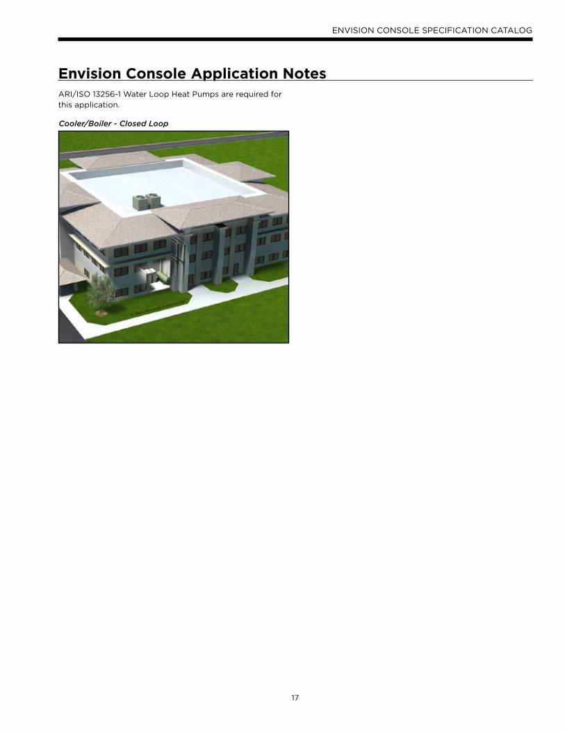
• Closed Loop /Cooler-Boiler Systems utilize a closed heat
recovering loop with multiple water source heat pumps in
the more conventional manner. Typically a boiler is em-
ployed to maintain closed loop temperatures above 60°r
and a cooling tower to maintain loop temperatures below
90°F. These systems are applicable in medium to large
buildings regardless of whether the load is heating or cool-
ing dominated. Due to the moderate loop temperatures,
pipe “heat exchangers.” Conversely if net space heating
demands cause loop heat absorption beyond that heat
recovered from building core areas, the loop temperature
will fall causing heat to be extracted from the earth. Due to
the extended loop temperatures, ARI/ISO 13256-1 Ground
Loop Heat Pumps are required for this application.
Because auxiliary equipment such as a fossil fuel boiler and
cooling tower are not required to maintain the loop tem-
perature, operating and maintenance costs are very low.
Ground-source systems are most applicable in residential
and light commercial buildings where both heating and
cooling are desired, and on larger envelope dominated
structures where core heat recovery will not meet over-
all heating loads. Both vertical and horizontally installed
closed-loops can be used. The land space required for
the “heat exchangers” is 100-250 sq. ft./ton on vertical
(drilled) installations and 750-1500 sq. ft./ton for horizon-
tal (trenched) installations. Closed loop heat exchangers
can be located under parking areas or even under the
building itself.
On large multi-unit systems, sizing the closed loop heat
exchanger to meet only the net heating loads and assisting
cooling loads with a closed circuit cooling tower may be
the most cost effective choice.
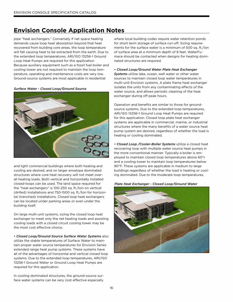
• Closed Loop/Ground-Source Surface Water Systems also
utilize the stable temperatures of Surface Water to main-
tain proper water source temperatures for Envision Series
extended range heat pump systems. These systems have
all of the advantages of horizontal and vertical closed loop
systems. Due to the extended loop temperatures, ARI/ISO
13256-1 Ground Water or Ground Loop Heat Pumps are
required for this application.
In cooling dominated structures, the ground-source sur-
face water systems can be very cost effective especially
Envision Console Application Notes
Surface Water - Closed Loop/Ground Source
Plate Heat Exchanger - Closed Loop/Ground Water
17
ENVISION CONSOLE SPECIFICATION CATALOG
Envision Console Application NotesARI/ISO 13256-1 Water Loop Heat Pumps are required for
this application.
Cooler/Boiler - Closed Loop
18
ENVISION CONSOLE SPECIFICATION CATALOG
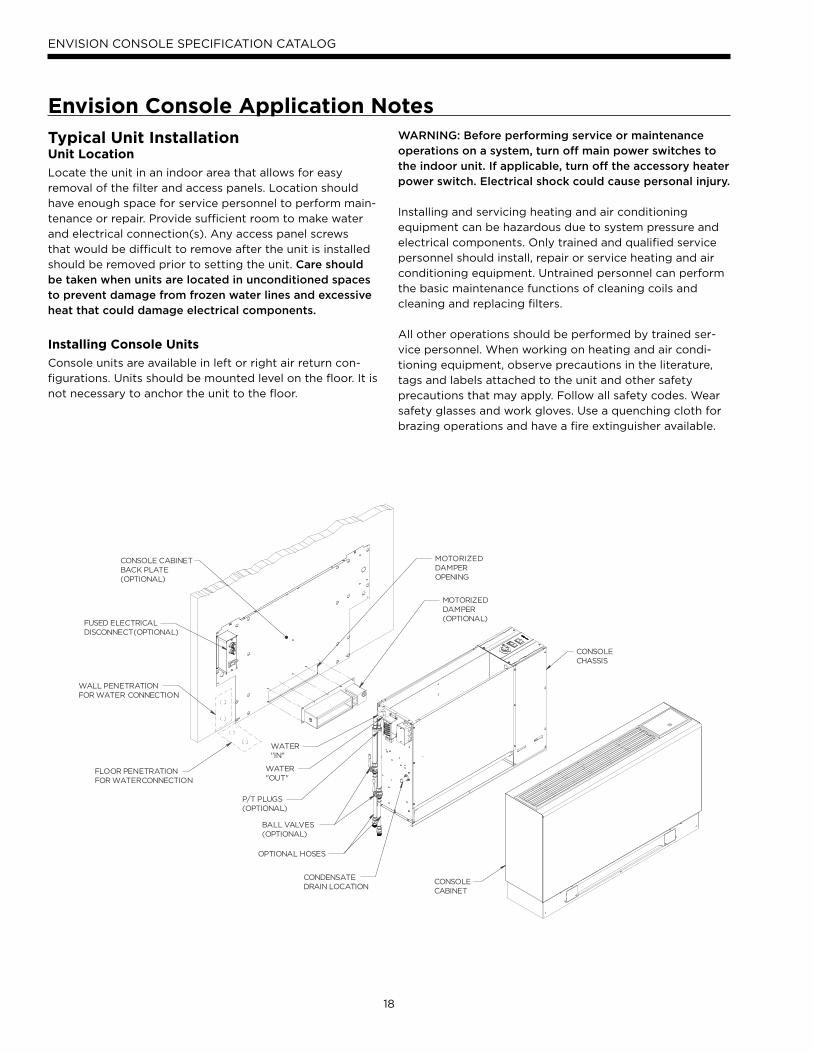
Typical Unit Installation Unit Location
Locate the unit in an indoor area that allows for easy
removal of the filter and access panels. Location should
have enough space for service personnel to perform main-
tenance or repair. Provide sufficient room to make water
and electrical connection(s). Any access panel screws
that would be difficult to remove after the unit is installed
should be removed prior to setting the unit. Care should be taken when units are located in unconditioned spaces to prevent damage from frozen water lines and excessive heat that could damage electrical components.
Installing Console Units
Console units are available in left or right air return con-
figurations. Units should be mounted level on the floor. It is
not necessary to anchor the unit to the floor.
WARNING: Before performing service or maintenance operations on a system, turn off main power switches to the indoor unit. If applicable, turn off the accessory heater power switch. Electrical shock could cause personal injury.
Installing and servicing heating and air conditioning
equipment can be hazardous due to system pressure and
electrical components. Only trained and qualified service
personnel should install, repair or service heating and air
conditioning equipment. Untrained personnel can perform
the basic maintenance functions of cleaning coils and
cleaning and replacing filters.
All other operations should be performed by trained ser-
vice personnel. When working on heating and air condi-
tioning equipment, observe precautions in the literature,
tags and labels attached to the unit and other safety
precautions that may apply. Follow all safety codes. Wear
safety glasses and work gloves. Use a quenching cloth for
brazing operations and have a fire extinguisher available.
CONSOLECABINET
CONSOLECHASSIS
CONDENSATEDRAIN LOCATION
OPTIONAL HOSES
BALL VALVES(OPTIONAL)
P/T PLUGS(OPTIONAL)
WATER"OUT"
WATER"IN"
CONSOLE CABINETBACK PLATE(OPTIONAL)
WALL PENETRATIONFOR WATER CONNECTION
FLOOR PENETRATIONFOR WATERCONNECTION
FUSED ELECTRICALDISCONNECT(OPTIONAL)
MOTORIZEDDAMPER(OPTIONAL)
MOTORIZEDDAMPEROPENING
Envision Console Application Notes
19
ENVISION CONSOLE SPECIFICATION CATALOG
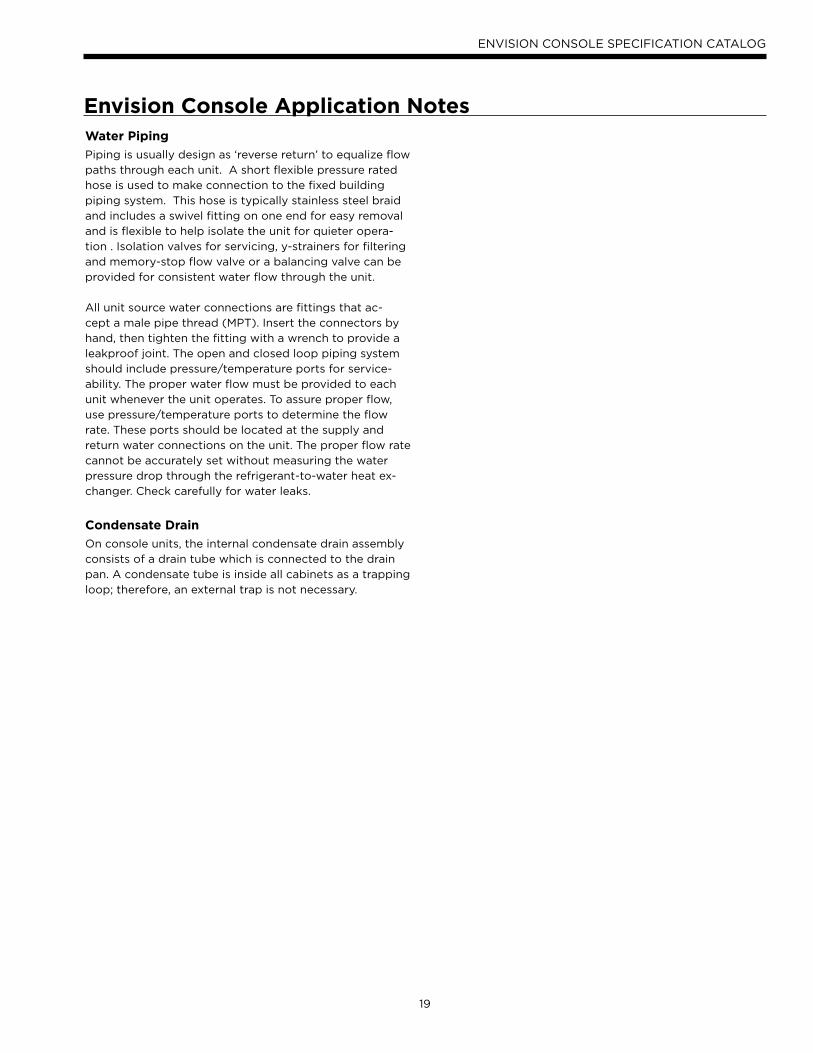
Water Piping
Piping is usually design as ‘reverse return’ to equalize flow
paths through each unit. A short flexible pressure rated
hose is used to make connection to the fixed building
piping system. This hose is typically stainless steel braid
and includes a swivel fitting on one end for easy removal
and is flexible to help isolate the unit for quieter opera-
tion . Isolation valves for servicing, y-strainers for filtering
and memory-stop flow valve or a balancing valve can be
provided for consistent water flow through the unit.
All unit source water connections are fittings that ac-
cept a male pipe thread (MPT). Insert the connectors by
hand, then tighten the fitting with a wrench to provide a
leakproof joint. The open and closed loop piping system
should include pressure/temperature ports for service-
ability. The proper water flow must be provided to each
unit whenever the unit operates. To assure proper flow,
use pressure/temperature ports to determine the flow
rate. These ports should be located at the supply and
return water connections on the unit. The proper flow rate
cannot be accurately set without measuring the water
pressure drop through the refrigerant-to-water heat ex-
changer. Check carefully for water leaks.
Condensate Drain
On console units, the internal condensate drain assembly
consists of a drain tube which is connected to the drain
pan. A condensate tube is inside all cabinets as a trapping
loop; therefore, an external trap is not necessary.
Envision Console Application Notes
20
ENVISION CONSOLE SPECIFICATION CATALOG
Selection ExampleTo achieve optimal performance, proper selection of each
heat pump is essential. A building load program should
be used to determine the heating and cooling load of each
zone. WFI Select computer software selection program
can then be used to develop an accurate and complete
heat pump schedule. WFI Select can be obtained from
your local WaterFurnace representative.
While WFI Select is the easiest and most accurate method
to size and select equipment, however, selection can still
be accomplished manually using this manual and the
following selection procedure. Sizing so that the actual
sensible capacity of the equipment will satisfy the sensible
capacity of the zone is the recommended method for best
results.
Boiler/Tower Application
Typical boiler/tower application will result in entering
water temperatures of 60-90°F with 70°F for heating and
90°F for cooling. Water to refrigerant insulation option
would not be required. Flow rates are 2.5 to 3 gpm per
ton with 2.5 gpm per ton often representing an economi-
cal design point.
Geothermal Application
Typical geothermal application can result in a wide enter-
ing water temperature range of 30-100°F. Typically mini-
mum heating entering water temperatures can range from
30 to 50°F depending upon loop type and geographical
location. Cooling performance should be calculated us-
ing a maximum loop temperature of 100°F in most loop
applications. Water flow is typically 2.5 to 3 gpm per ton
with 3 gpm per ton recommended with the more extreme
loop temperatures. PLEASE NOTE THAT WATER COIL INSULATION OPTION SHOULD BE SELECTED WHEN ENTERING WATER TEMPERATURES ARE EXPECTED TO BE BELOW 45-50°F.
Geothermal Selection ExampleStep 1: Determine the actual heating and cooling loads at
the desired dry bulb and wet bulb conditions.
Step 2: Obtain the following de sign parameters: Enter-
ing water temperature, water flow rate in GPM, air flow in
CFM, water flow pressure drop and design wet and dry
bulb temperatures. Air flow CFM should be between 300
and 450 CFM per ton. Unit water pressure drop should
be kept as close as possible to each other to make water
balancing easier. Go to the appropriate tables and find the
proper indicated water flow and water temperature.
Step 3: Select a unit based on total and sensible cooling
conditions. Select a unit which is closest to, but no larger
than, the actual cooling load.
Step 4: Enter tables at the design water flow and water
temperature. Read the total and sensible cooling capaci-
ties (Note: interpolation is permissible, extrapolation is
not).
Step 5: Read the heating capacity. If it exceeds the design
criteria it is acceptable. It is quite normal for water source
heat pumps to be selected on cooling capacity only since
the heating output is usually greater than the cooling
capacity.
Step 6: Determine the correction factors associated with
the variable factors of dry bulb and wet bulb.
Corrected Total Cooling = tabulated total cooling x wet
bulb correction.
Corrected Sensible Cooling = tabulated sensible cooling x
wet/dry bulb correction.
Step 7: Compare the corrected capacities to the load
requirements. Normally if the capacities are within 10%
of the loads, the equipment is acceptable. It is better to
undersize than oversize, as undersizing improves humidity
control, reduces sound levels and extends the life of the
equipment.
Step 8: When complete, calculate water temperature
rise and assess the selection. If the units selected are not
within 10% of the load calculations, then review what ef-
fect changing the GPM, water temperature and/or air flow
and air temperature would have on the corrected capaci-
ties. If the desired capacity cannot be achieved, select
the next larger or smaller unit and repeat the procedure.
Remember, when in doubt, undersize slightly for best
performance.
Example Equipment Selection - Cooling
1. Load Determination:Assume we have determined that the appropriate cool-
ing load at the desired dry bulb 75°F and wet bulb 60°F
conditions is as follows:
Total Cooling ................................................................14,800 BTUH
Sensible Cooling .......................................................... 11,200 BTUH
Entering Air Temp ................. 75°F Dry Bulb / 60°F Wet Bulb
2. Design Conditions:Similarly, we have also obtained the following design
parameters:
Entering Water Temp.............................................................. 100°F
Water Flow (Based upon 10°F rise in temp.) 5.5 GPM
Air Flow Required ..............................................................450 CFM
21
ENVISION CONSOLE SPECIFICATION CATALOG
3, 4 & 5. HP Selection:After making our preliminary selection (NC18), we enter
the tables at design water flow and water temperature
and read
Total Cooling, Sens. Cooling and Heat of Rej. capacities:
Total Cooling ................................................................16,600 BTUH
Sensible Cooling .........................................................12,600 BTUH
Heat of Rejection .......................................................21,400 BTUH
6 & 7. Entering Air and Airflow Corrections: Next, we determine our correction factors. (Refer to Cor-
rection Factor Tables - Air Flow and Entering Air correc-
tion tables — using 450 cfm. or 450÷500 nom. = 90%).
Corrected Total Cooling = 16,600 x 0.982 x 0.897 = 14,622
Corrected Sens Cooling = 12,600 x 0.933 x 0.995 = 11,697
Corrected Heat of Reject = 21,400 x 0.980 x 0.895 = 18,770
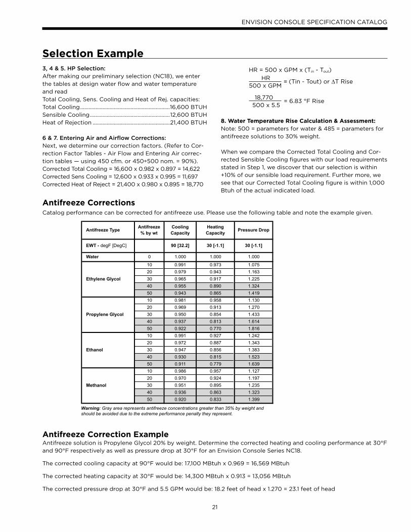
8. Water Temperature Rise Calculation & Assessment: Note: 500 = parameters for water & 485 = parameters for
antifreeze solutions to 30% weight.
When we compare the Corrected Total Cooling and Cor-
rected Sensible Cooling figures with our load requirements
stated in Step 1, we discover that our selection is within
+10% of our sensible load requirement. Further more, we
see that our Corrected Total Cooling figure is within 1,000
Btuh of the actual indicated load.
Selection Example
Antifreeze CorrectionsCatalog performance can be corrected for antifreeze use. Please use the following table and note the example given.
Antifreeze Correction ExampleAntifreeze solution is Propylene Glycol 20% by weight. Determine the corrected heating and cooling performance at 30°F
and 90°F respectively as well as pressure drop at 30°F for an Envision Console Series NC18.
The corrected cooling capacity at 90°F would be: 17,100 MBtuh x 0.969 = 16,569 MBtuh
The corrected heating capacity at 30°F would be: 14,300 MBtuh x 0.913 = 13,056 MBtuh
The corrected pressure drop at 30°F and 5.5 GPM would be: 18.2 feet of head x 1.270 = 23.1 feet of head
Antifreeze TypeAntifreeze% by wt
Cooling Capacity
Heating Capacity
Pressure Drop
EWT - degF [DegC] 90 [32.2] 30 [-1.1] 30 [-1.1]
Water 0 1.000 1.000 1.000
10 0.991 0.973 1.075
20 0.979 0.943 1.163
Ethylene Glycol 30 0.965 0.917 1.225
40 0.955 0.890 1.324
50 0.943 0.865 1.419
10 0.981 0.958 1.130
20 0.969 0.913 1.270
Propylene Glycol 30 0.950 0.854 1.433
40 0.937 0.813 1.614
50 0.922 0.770 1.816
10 0.991 0.927 1.242
20 0.972 0.887 1.343
Ethanol 30 0.947 0.856 1.383
40 0.930 0.815 1.523
50 0.911 0.779 1.639
10 0.986 0.957 1.127
20 0.970 0.924 1.197
Methanol 30 0.951 0.895 1.235
40 0.936 0.863 1.323
50 0.920 0.833 1.399
Warning: Gray area represents antifreeze concentrations greater than 35% by weight and should be avoided due to the extreme performance penalty they represent.
HR = 500 x GPM x (Tin - Tout)
HR= (Tin - Tout) or ∆T Rise
500 x GPM
18,770= 6.83 °F Rise
500 x 5.5
22
ENVISION CONSOLE SPECIFICATION CATALOG
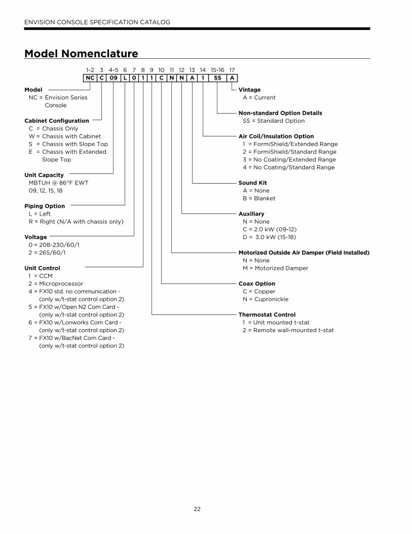
Model Nomenclature1-2
NC3
C4-5
096
L7
08
19
110
C11
N12
N13
A14
115-16
SS17
A
Model NC = Envision Series
Console
Cabinet Configuration C = Chassis Only
W = Chassis with Cabinet
S = Chassis with Slope Top
E = Chassis with Extended
Slope Top
Unit Capacity MBTUH @ 86°F EWT
09, 12, 15, 18
Piping Option L = Left
R = Right (N/A with chassis only)
Voltage 0 = 208-230/60/1
2 = 265/60/1
Unit Control 1 = CCM
2 = Microprocessor
4 = FX10 std. no communication -
(only w/t-stat control option 2)
5 = FX10 w/Open N2 Com Card -
(only w/t-stat control option 2)
6 = FX10 w/Lonworks Com Card -
(only w/t-stat control option 2)
7 = FX10 w/BacNet Com Card -
(only w/t-stat control option 2)
Vintage A = Current
Non-standard Option Details SS = Standard Option
Air Coil/Insulation Option 1 = FormiShield/Extended Range
2 = FormiShield/Standard Range
3 = No Coating/Extended Range
4 = No Coating/Standard Range
Sound Kit A = None
B = Blanket
Auxiliary N = None
C = 2.0 kW (09-12)
D = 3.0 kW (15-18)
Motorized Outside Air Damper (Field Installed) N = None
M = Motorized Damper
Coax Option C = Copper
N = Cupronickle
Thermostat Control 1 = Unit mounted t-stat
2 = Remote wall-mounted t-stat
23
ENVISION CONSOLE SPECIFICATION CATALOG
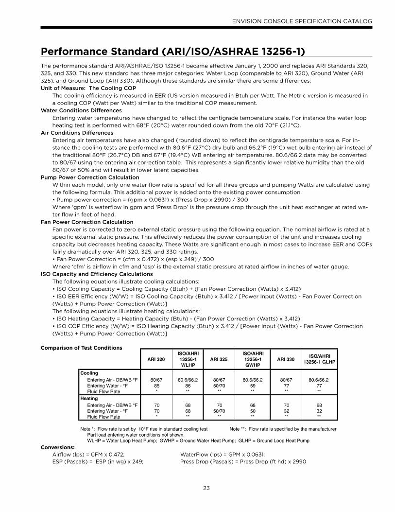
The performance standard ARI/ASHRAE/ISO 13256-1 became effective January 1, 2000 and replaces ARI Standards 320,
325, and 330. This new standard has three major categories: Water Loop (comparable to ARI 320), Ground Water (ARI
325), and Ground Loop (ARI 330). Although these standards are similar there are some differences:
Unit of Measure: The Cooling COPThe cooling efficiency is measured in EER (US version measured in Btuh per Watt. The Metric version is measured in
a cooling COP (Watt per Watt) similar to the traditional COP measurement.
Water Conditions DifferencesEntering water temperatures have changed to reflect the centigrade temperature scale. For instance the water loop
heating test is performed with 68°F (20°C) water rounded down from the old 70°F (21.1°C).
Air Conditions DifferencesEntering air temperatures have also changed (rounded down) to reflect the centigrade temperature scale. For in-
stance the cooling tests are performed with 80.6°F (27°C) dry bulb and 66.2°F (19°C) wet bulb entering air instead of
the traditional 80°F (26.7°C) DB and 67°F (19.4°C) WB entering air temperatures. 80.6/66.2 data may be converted
to 80/67 using the entering air correction table. This represents a significantly lower relative humidity than the old
80/67 of 50% and will result in lower latent capacities.
Pump Power Correction CalculationWithin each model, only one water flow rate is specified for all three groups and pumping Watts are calculated using
the following formula. This additional power is added onto the existing power consumption.
• Pump power correction = (gpm x 0.0631) x (Press Drop x 2990) / 300
Where ‘gpm’ is waterflow in gpm and ‘Press Drop’ is the pressure drop through the unit heat exchanger at rated wa-
ter flow in feet of head.
Fan Power Correction CalculationFan power is corrected to zero external static pressure using the following equation. The nominal airflow is rated at a
specific external static pressure. This effectively reduces the power consumption of the unit and increases cooling
capacity but decreases heating capacity. These Watts are significant enough in most cases to increase EER and COPs
fairly dramatically over ARI 320, 325, and 330 ratings.
• Fan Power Correction = (cfm x 0.472) x (esp x 249) / 300
Where ‘cfm’ is airflow in cfm and ‘esp’ is the external static pressure at rated airflow in inches of water gauge.
ISO Capacity and Efficiency CalculationsThe following equations illustrate cooling calculations:
• ISO Cooling Capacity = Cooling Capacity (Btuh) + (Fan Power Correction (Watts) x 3.412)
• ISO EER Efficiency (W/W) = ISO Cooling Capacity (Btuh) x 3.412 / [Power Input (Watts) - Fan Power Correction
(Watts) + Pump Power Correction (Watt)]
The following equations illustrate heating calculations:
• ISO Heating Capacity = Heating Capacity (Btuh) - (Fan Power Correction (Watts) x 3.412)
• ISO COP Efficiency (W/W) = ISO Heating Capacity (Btuh) x 3.412 / [Power Input (Watts) - Fan Power Correction
(Watts) + Pump Power Correction (Watt)]
Comparison of Test Conditions
Conversions: Airflow (lps) = CFM x 0.472; WaterFlow (lps) = GPM x 0.0631; ESP (Pascals) = ESP (in wg) x 249; Press Drop (Pascals) = Press Drop (ft hd) x 2990
Performance Standard (ARI/ISO/ASHRAE 13256-1)
ARI 320ISO/AHRI 13256-1 WLHP
ARI 325ISO/AHRI 13256-1 GWHP
ARI 330 ISO/AHRI 13256-1 GLHP
CoolingEntering Air - DB/WB °F 80/67 80.6/66.2 80/67 80.6/66.2 80/67 80.6/66.2Entering Water - °F 85 86 50/70 59 77 77Fluid Flow Rate * ** ** ** ** **
HeatingEntering Air - DB/WB °F 70 68 70 68 70 68Entering Water - °F 70 68 50/70 50 32 32Fluid Flow Rate * ** ** ** ** **
Note *: Flow rate is set by 10°F rise in standard cooling test Note **: Flow rate is specified by the manufacturerPart load entering water conditions not shown.WLHP = Water Loop Heat Pump; GWHP = Ground Water Heat Pump; GLHP = Ground Loop Heat Pump
24
ENVISION CONSOLE SPECIFICATION CATALOG
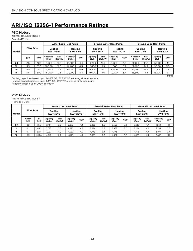
ARI/ISO 13256-1 Performance RatingsPSC Motors ARI/ASHRAE/ISO 13256-1
English (IP) Units
Model
Flow Rate
Water Loop Heat Pump Ground Water Heat Pump Ground Loop Heat Pump
Cooling EWT 86°F
Heating EWT 68°F
Cooling EWT 59°F
Heating EWT 50°F
Cooling EWT 77°F
Heating EWT 32°F
gpm cfmCapacity
Btuh EER
Btuh/WCapacity
Btuh COP
Capacity Btuh
EER Btuh/W
Capacity Btuh
COPCapacity
Btuh EER
Btuh/WCapacity
Btuh COP
09 2.5 300 8,500 13.4 10,500 4.4 10,200 22.5 8,700 3.8 9,000 16.0 6,700 3.1
12 3.5 350 10,500 12.3 14,400 4.3 12,400 19.5 11,800 3.7 11,000 14.2 9,500 3.5
15 4.5 450 13,500 13.6 17,000 4.9 16,200 22.0 14,000 4.1 14,200 15.9 10,500 3.4
18 5.5 500 16,200 12.5 21,000 4.4 19,000 19.6 17,000 3.7 16,600 15.1 13,300 3.1
3/3/08Cooling capacities based upon 80.6°F DB, 66.2°F WB entering air temperatureHeating capacities based upon 68°F DB, 59°F WB entering air temperatureAll ratings based upon 208V operation
PSC Motors ARI/ASHRAE/ISO 13256-1
Metric (SI) Units
Model
Flow Rate
Water Loop Heat Pump Ground Water Heat Pump Ground Loop Heat Pump
Cooling EWT 30°C
Heating EWT 20°C
Cooling EWT 15°C
Heating EWT 10°C
Cooling EWT 25°C
Heating EWT 0°C
water L/S
air L/S
Capacity Watts
EER (W/W)
Capacity Watts
COP Capacity
Watts EER
(W/W) Capacity
Watts COP
Capacity Watts
EER (W/W)
Capacity Watts
COP
09 0.2 141.6 2,491 3.9 3,077 4.4 2,989 6.6 2,550 3.8 2,638 4.7 1,964 3.1
12 0.2 165.2 3,077 3.6 4,220 4.3 3,634 5.7 3,458 3.7 3,224 4.2 2,784 3.5
15 0.3 212.4 3,957 4.0 4,982 4.9 4,748 6.4 4,103 4.1 4,162 4.7 3,077 3.4
18 0.3 236.0 4,748 3.7 6,155 4.4 5,569 5.7 4,982 3.7 4,865 4.4 3,898 3.1
25
ENVISION CONSOLE SPECIFICATION CATALOG
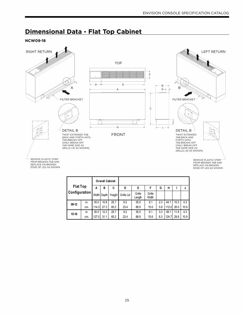
NCW09-18
Overall Cabinet
Flat Top
ConfigurationA B C D E F G H I J
Width Depth Height Grille Lid Grille Length
Grille Width
in. 45.0 10.8 25.7 9.2 35.0 6.1 2.3 44.1 10.3 4.3
cm. 114.3 27.3 65.2 23.4 88.9 15.6 5.8 112.0 26.0 10.9
in. 50.0 12.3 25.7 9.2 35.0 6.1 3.3 49.1 11.8 4.3
cm. 127.0 31.1 65.2 23.4 88.9 15.6 8.3 124.7 29.8 10.9
09-12
15-18
F
B
G
I
J
C
ED
A
H
FILTER BRACKET FILTER BRACKET
RIGHT RETURN
TOP
FRONT
LEFT RETURN
DETAIL BTWIST EXTENDEDTAB BACK ANDFORTH UNTILTAB BREAKS OFF(ONLY BREAK-OFFTAB SAME SIDE ASGRILLE LID AS SHOWN)
DETAIL BTWIST EXTENDED TABBACK AND FORTH UNTILTAB BREAKS OFF(ONLY BREAK-OFFTAB SAME SIDE ASGRILLE LID AS SHOWN)
BA
REMOVE PLASTIC STRIPFROM BROKEN TAB ANDREPLACE ON BROKENEDGE OF LEG AS SHOWN
REMOVE PLASTIC STRIPFROM BROKEN TAB ANDREPLACE ON BROKENEDGE OF LEG AS SHOWN
Dimensional Data - Flat Top Cabinet
26
ENVISION CONSOLE SPECIFICATION CATALOG
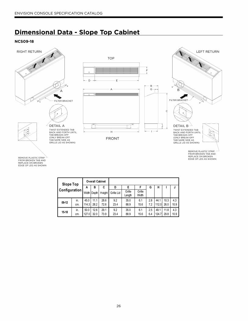
NCS09-18
Overall CabinetSlope Top
ConfigurationA B C D E F G H I J
Width Depth Height Grille Lid Grille Length
Grille Width
in. 45.0 11.1 28.6 9.2 35.0 6.1 2.8 44.1 10.3 4.3cm. 114.3 28.2 72.6 23.4 88.9 15.6 7.2 112.0 26.0 10.9in. 50.0 12.6 29.1 9.2 35.0 6.1 2.5 49.1 11.8 4.3
cm. 127.0 32.0 73.9 23.4 88.9 15.6 6.4 124.7 29.8 10.9
09-12
15-18
REMOVE PLASTIC STRIPFROM BROKEN TAB ANDREPLACE ON BROKENEDGE OF LEG AS SHOWN
H I
J
C
F
E
A
D
G
B
RIGHT RETURN
TOP
FRONT
LEFT RETURN
DETAIL BTWIST EXTENDED TABBACK AND FORTH UNTILTAB BREAKS OFF(ONLY BREAK-OFFTAB SAME SIDE ASGRILLE LID AS SHOWN)
DETAIL ATWIST EXTENDED TABBACK AND FORTH UNTILTAB BREAKS OFF(ONLY BREAK-OFFTAB SAME SIDE ASGRILLE LID AS SHOWN)
REMOVE PLASTIC STRIPFROM BROKEN TAB ANDREPLACE ON BROKENEDGE OF LEG AS SHOWN
BA
FILTER BRACKETFILTER BRACKET
Dimensional Data - Slope Top Cabinet
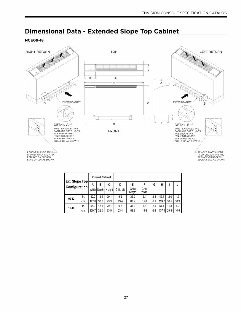
27
ENVISION CONSOLE SPECIFICATION CATALOG
NCE09-18
REMOVE PLASTIC STRIPFROM BROKEN TAB ANDREPLACE ON BROKENEDGE OF LEG AS SHOWN
Overall CabinetExt. Slope Top
Configuration A B C D E F G H I JWidth Depth Height Grille Lid Grille
LengthGrille Width
in. 50.0 12.6 29.1 9.2 35.0 6.1 2.4 49.1 12.0 4.3cm. 127.0 32.0 73.9 23.4 88.9 15.6 6.1 124.7 30.5 10.9in. 55.0 12.6 29.1 9.2 35.0 6.1 2.5 54.1 11.8 4.3
cm. 139.7 32.0 73.9 23.4 88.9 15.6 6.4 137.4 29.8 10.9
09-12
15-18
FILTER BRACKETFILTER BRACKET
A
D E
C
H I
J
F
B
G
A B
RIGHT RETURN TOP
FRONT
LEFT RETURN
DETAIL BTWIST EXTENDED TABBACK AND FORTH UNTILTAB BREAKS OFF(ONLY BREAK-OFFTAB SAME SIDE ASGRILLE LID AS SHOWN)
DETAIL ATWIST EXTENDED TABBACK AND FORTH UNTILTAB BREAKS OFF(ONLY BREAK-OFFTAB SAME SIDE ASGRILLE LID AS SHOWN)
REMOVE PLASTIC STRIPFROM BROKEN TAB ANDREPLACE ON BROKENEDGE OF LEG AS SHOWN
Dimensional Data - Extended Slope Top Cabinet
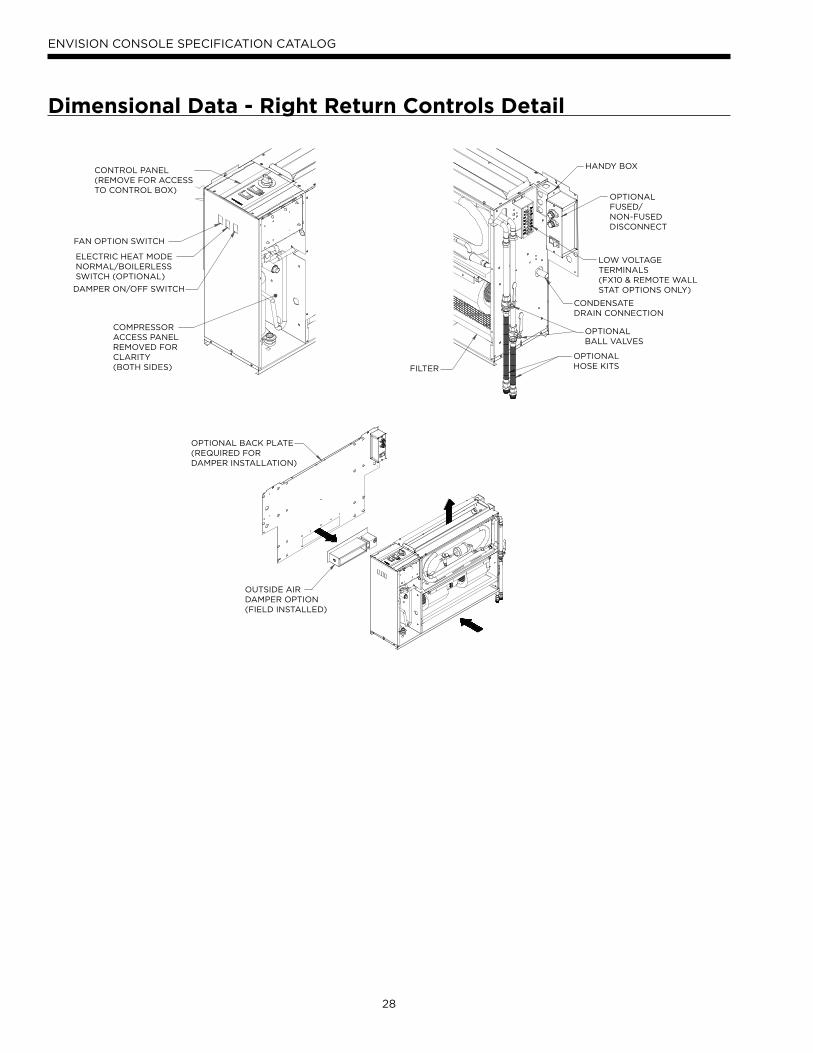
28
ENVISION CONSOLE SPECIFICATION CATALOG
CONTROL PANEL(REMOVE FOR ACCESSTO CONTROL BOX)
DAMPER ON/OFF SWITCH
COMPRESSORACCESS PANELREMOVED FORCLARITY(BOTH SIDES)
ELECTRIC HEAT MODENORMAL/BOILERLESSSWITCH (OPTIONAL)
FAN OPTION SWITCH
OPTIONAL BACK PLATE(REQUIRED FORDAMPER INSTALLATION)
OUTSIDE AIRDAMPER OPTION(FIELD INSTALLED)
LOW VOLTAGETERMINALS(FX10 & REMOTE WALLSTAT OPTIONS ONLY)
OPTIONALFUSED/NON-FUSEDDISCONNECT
OPTIONALBALL VALVES
OPTIONALHOSE KITS
CONDENSATEDRAIN CONNECTION
FILTER
HANDY BOX
Dimensional Data - Right Return Controls Detail
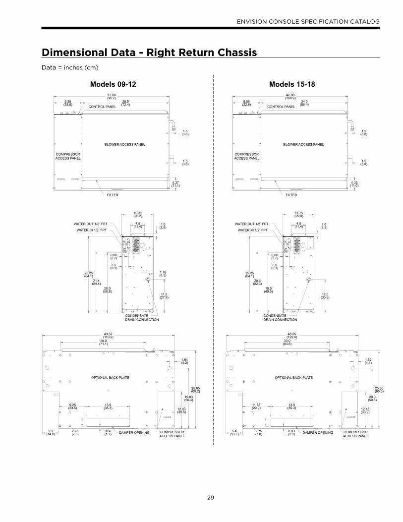
29
ENVISION CONSOLE SPECIFICATION CATALOG
BLOWER ACCESS PANEL
COMPRESSORACCESS PANEL
37.88(96.2)
28.5(72.4)
1.5(3.8)
1.5(3.8)
4.37(11.1)
9.38(23.8)
FILTER
CONTROL PANEL
25.25(64.1)
0.86(2.2)
10.31(26.2)
1.0(2.5)
1.78(4.5)
11.0(27.9)
4.5(11.4)
2.0(5.1)
21.4(54.4)
20.0(50.8)
CONDENSATEDRAIN CONNECTION
WATER OUT 1/2˝ FPT
WATER IN 1/2˝ FPT
OPTIONAL BACK PLATE
COMPRESSORACCESS PANEL
43.37(110.2)
28.0(71.1)
9.25(23.5)
13.9(35.3)
25.65(65.2)
19.83(50.4)
1.64(4.2)
12.03(30.6)
0.66(1.7)
2.75(7.0)
5.5(14.0) DAMPER OPENING
Models 09-12
BLOWER ACCESS PANEL
COMPRESSORACCESS PANEL
42.88(108.9)
34.0(86.4)
1.5(3.8)
1.5(3.8)
4.32(11.0)
8.88(22.6)
FILTER
CONTROL PANEL
25.25(64.1)
0.86(2.2)
11.75(29.8)
1.0(2.5)
12.0(30.5)
4.5(11.4)
2.0(5.1)
20.6(52.3)
19.5(49.5)
CONDENSATEDRAIN CONNECTION
WATER OUT 1/2˝ FPT
WATER IN 1/2˝ FPT
OPTIONAL BACK PLATE
COMPRESSORACCESS PANEL
48.25(122.6)
33.0(83.8)
11.78(29.9)
13.9(35.3)
25.80(65.5)
20.0(50.8)
1.62(4.1)
12.18(30.9)
0.83(2.1)
2.75(7.0)
5.4(13.7) DAMPER OPENING
Models 15-18
Dimensional Data - Right Return ChassisData = inches (cm)
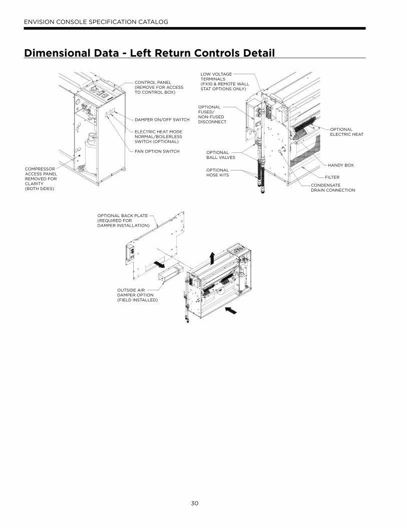
30
ENVISION CONSOLE SPECIFICATION CATALOG
LOW VOLTAGETERMINALS(FX10 & REMOTE WALLSTAT OPTIONS ONLY)
OPTIONALFUSED/NON-FUSEDDISCONNECT
OPTIONALBALL VALVES
OPTIONALHOSE KITS
CONDENSATEDRAIN CONNECTION
FILTER
HANDY BOX
OPTIONALELECTRIC HEAT
OPTIONAL BACK PLATE(REQUIRED FORDAMPER INSTALLATION)
OUTSIDE AIRDAMPER OPTION(FIELD INSTALLED)
CONTROL PANEL(REMOVE FOR ACCESSTO CONTROL BOX)
DAMPER ON/OFF SWITCH
COMPRESSORACCESS PANELREMOVED FORCLARITY(BOTH SIDES)
ELECTRIC HEAT MODENORMAL/BOILERLESSSWITCH (OPTIONAL)
FAN OPTION SWITCH
Dimensional Data - Left Return Controls Detail
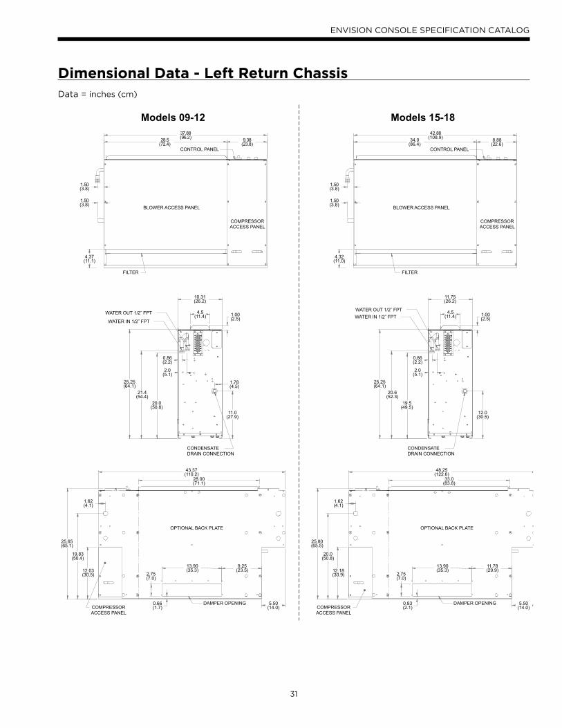
31
ENVISION CONSOLE SPECIFICATION CATALOG
9.38(23.8)
28.5(72.4)
1.50(3.8)
1.50(3.8)
4.37(11.1)
37.88(96.2)
BLOWER ACCESS PANEL
COMPRESSORACCESS PANEL
FILTER
CONTROL PANEL
1.00(2.5)
10.31(26.2)
4.5(11.4)
0.86(2.2)
2.0(5.1)
25.25(64.1)
21.4(54.4)
20.0(50.8)
1.78(4.5)
11.0(27.9)
CONDENSATEDRAIN CONNECTION
WATER OUT 1/2˝ FPT
WATER IN 1/2˝ FPT
28.00(71.1)
13.90(35.3)
9.25(23.5)
2.75(7.0)
12.03(30.5)
0.66(1.7)
5.50(14.0)
OPTIONAL BACK PLATE
COMPRESSORACCESS PANEL
DAMPER OPENING
43.37(110.2)
1.62(4.1)
25.65(65.1)
19.83(50.4)
Models 09-12
8.88(22.6)
34.0(86.4)
1.50(3.8)
1.50(3.8)
4.32(11.0)
42.88(108.9)
BLOWER ACCESS PANEL
COMPRESSORACCESS PANEL
FILTER
CONTROL PANEL
1.00(2.5)
11.75(26.2)
4.5(11.4)
0.86(2.2)
2.0(5.1)
25.25(64.1)
20.6(52.3)
19.5(49.5)
12.0(30.5)
CONDENSATEDRAIN CONNECTION
WATER OUT 1/2˝ FPTWATER IN 1/2˝ FPT
33.0(83.8)
13.90(35.3)
11.78(29.9)
2.75(7.0)
12.18(30.9)
0.83(2.1)
5.50(14.0)
OPTIONAL BACK PLATE
COMPRESSORACCESS PANEL
DAMPER OPENING
48.25(122.6)
1.62(4.1)
25.80(65.5)
20.0(50.8)
Models 15-18
Dimensional Data - Left Return ChassisData = inches (cm)
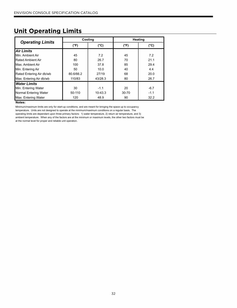
32
ENVISION CONSOLE SPECIFICATION CATALOG
Operating Limits(°F) (°C) (°F) (°C)
Air LimitsMin. Ambient Air 45 7.2 45 7.2
Rated Ambient Air 80 26.7 70 21.1
Max. Ambient Air 100 37.8 85 29.4
Min. Entering Air 50 10.0 40 4.4
Rated Entering Air db/wb 80.6/66.2 27/19 68 20.0
Max. Entering Air db/wb 110/83 43/28.3 80 26.7
Water LimitsMin. Entering Water 30 -1.1 20 -6.7
Normal Entering Water 50-110 10-43.3 30-70 -1.1
Max. Entering Water 120 48.9 90 32.2
Notes:
Cooling Heating
Minimum/maximum limits are only for start-up conditions, and are meant for bringing the space up to occupancy
temperature. Units are not designed to operate at the minimum/maximum conditions on a regular basis. The
operating limits are dependant upon three primary factors: 1) water temperature, 2) return air temperature, and 3)
ambient temperature. When any of the factors are at the minimum or maximum levels, the other two factors must be
at the normal level for proper and reliable unit operation.
Unit Operating Limits
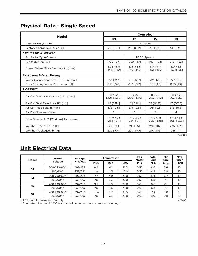
33
ENVISION CONSOLE SPECIFICATION CATALOG
Physical Data - Single Speed
ModelConsoles
09 12 15 18Compressor (1 each) LG Rotary
Factory Charge R410A, oz [kg] 25 [0.71] 29 [0.82] 38 [1.08] 34 [0.96]
Fan Motor & BlowerFan Motor Type/Speeds PSC 2 Speeds
Fan Motor- hp [W] 1/20 [37] 1/20 [37] 1/12 [62] 1/12 [62]
Blower Wheel Size (Dia x W), in. [mm]5.75 x 5.5
[146 x 140]5.75 x 5.5
[146 x 140]6.0 x 6.5
[152 x 165]6.0 x 6.5
[152 x 165]
Coax and Water Piping
Water Connections Size - FPT - in [mm] 1/2” [12.7] 1/2” [12.7] 1/2” [12.7] 1/2” [12.7]
Coax & Piping Water Volume - gal [l] 0.15 [0.6] 0.18 [0.7] 0.35 [1.3] 0.35 [1.3]
Consoles
Air Coil Dimensions (H x W), in. [mm]8 x 22
[203 x 559]8 x 22
[203 x 559]8 x 30
[203 x 762]8 x 30
[203 x 762]
Air Coil Total Face Area, ft2 [m2] 1.2 [0.114] 1.2 [0.114] 1.7 [0.155] 1.7 [0.155]
Air Coil Tube Size, in [mm] 3/8 [9.5] 3/8 [9.5] 3/8 [9.5] 3/8 [9.5]
Air Coil Number of rows 3 3 4 4
Filter Standard - 1” [25.4mm] Throwaway1 - 10 x 28 [254 x 711]
1 - 10 x 28 [254 x 711]
1 - 12 x 33 [305 x 838]
1 - 12 x 33 [305 x 838]
Weight - Operating, lb [kg] 210 [91] 210 [95] 230 [102] 235 [107]
Weight - Packaged, lb [kg] 220 [100] 220 [100] 240 [109] 245 [111]
3/4/08
Unit Electrical Data
ModelRated
VoltageVoltageMin/Max
Compressor FanMotorFLA
TotalUnitFLA
MinCircAmp
MaxFuse/HACRMCC RLA LRA
09208-230/60/1 197/253 6.4 4.1 21.0 0.50 4.6 5.6 10
265/60/1* 238/292 na 4.3 22.0 0.50 4.8 5.9 10
12208-230/60/1 197/253 7.7 4.9 25.0 0.50 5.4 6.7 10
265/60/1* 238/292 na 5.3 22.0 0.50 5.8 7.1 10
15208-230/60/1 197/253 9.2 5.9 29.0 0.69 6.6 8.1 10
265/60/1* 238/292 na 5.6 28.0 0.65 6.3 7.7 10
18208-230/60/1 197/253 10.4 6.7 33.5 0.69 7.3 9.0 15
265/60/1* 238/292 na 7.3 28.0 0.65 8.0 9.8 15
HACR circuit breaker in USA only* RLA determine per UL1995 test procedure and not from compressor rating.
4/8/08
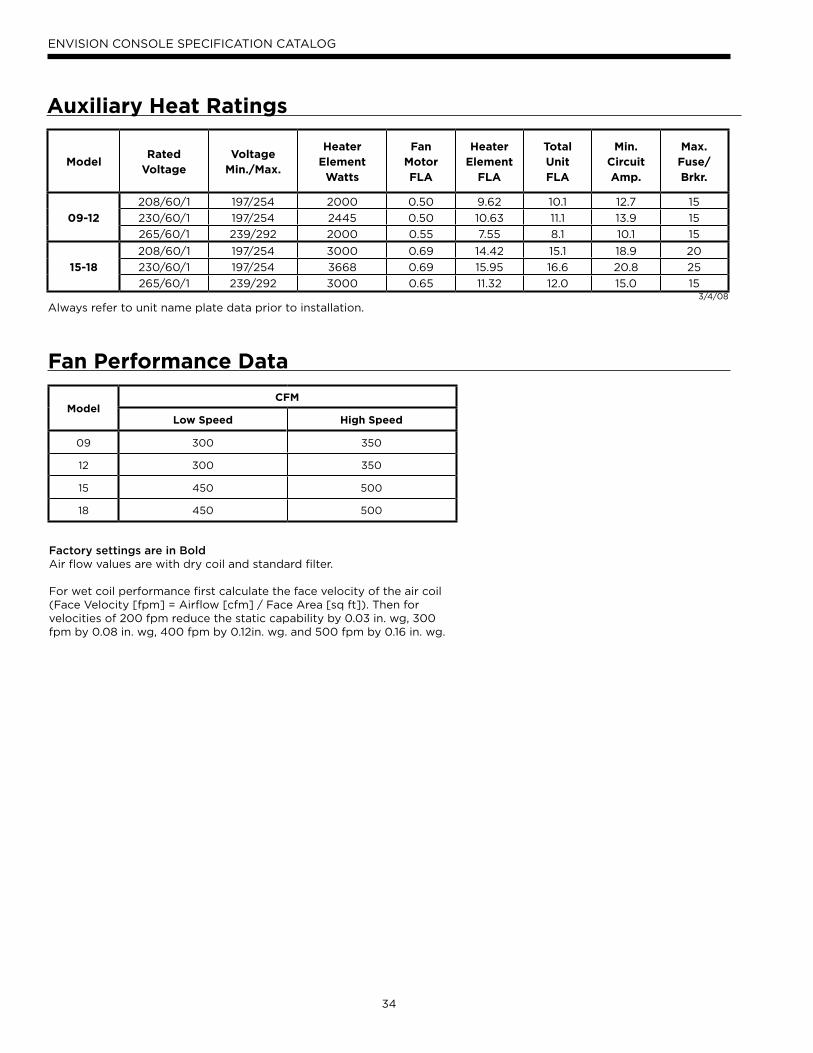
34
ENVISION CONSOLE SPECIFICATION CATALOG
Auxiliary Heat Ratings
ModelRated
VoltageVoltage
Min./Max.
HeaterElement
Watts
Fan MotorFLA
HeaterElement
FLA
TotalUnitFLA
Min.CircuitAmp.
Max.Fuse/Brkr.
09-12
208/60/1 197/254 2000 0.50 9.62 10.1 12.7 15
230/60/1 197/254 2445 0.50 10.63 11.1 13.9 15
265/60/1 239/292 2000 0.55 7.55 8.1 10.1 15
15-18
208/60/1 197/254 3000 0.69 14.42 15.1 18.9 20
230/60/1 197/254 3668 0.69 15.95 16.6 20.8 25
265/60/1 239/292 3000 0.65 11.32 12.0 15.0 153/4/08
Always refer to unit name plate data prior to installation.
ModelCFM
Low Speed High Speed
09 300 350
12 300 350
15 450 500
18 450 500
Factory settings are in BoldAir flow values are with dry coil and standard filter. For wet coil performance first calculate the face velocity of the air coil (Face Velocity [fpm] = Airflow [cfm] / Face Area [sq ft]). Then for velocities of 200 fpm reduce the static capability by 0.03 in. wg, 300 fpm by 0.08 in. wg, 400 fpm by 0.12in. wg. and 500 fpm by 0.16 in. wg.
Fan Performance Data
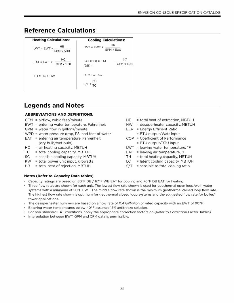
35
ENVISION CONSOLE SPECIFICATION CATALOG
Reference Calculations
Heating Calculations: Cooling Calculations:
LWT = EWT +
LAT (DB) = EAT
(DB) -
LC = TC - SC
S/T =
HR
GPM x 500
SC
CFM x 1.08
SCTC
LWT = EWT -
LAT = EAT +
TH = HC + HW
HE
GPM x 500
HCCFM x 1.08
Legends and NotesABBREVIATIONS AND DEFINITIONS:
CFM = airflow, cubic feet/minuteEWT = entering water temperature, FahrenheitGPM = water flow in gallons/minuteWPD = water pressure drop, PSI and feet of waterEAT = entering air temperature, Fahrenheit (dry bulb/wet bulb)HC = air heating capacity, MBTUHTC = total cooling capacity, MBTUHSC = sensible cooling capacity, MBTUHKW = total power unit input, kilowattsHR = total heat of rejection, MBTUH
HE = total heat of extraction, MBTUHHW = desuperheater capacity, MBTUHEER = Energy Efficient Ratio = BTU output/Watt inputCOP = Coefficient of Performance = BTU output/BTU inputLWT = leaving water temperature, °FLAT = leaving air temperature, °FTH = total heating capacity, MBTUHLC = latent cooling capacity, MBTUHS/T = sensible to total cooling ratio
Notes (Refer to Capacity Data tables)
Capacity ratings are based on 80°F DB / 67°F WB EAT for cooling and 70°F DB EAT for heating.•
Three flow rates are shown for each unit. The lowest flow rate shown is used for geothermal open loop/well water •
systems with a minimum of 50°F EWT. The middle flow rate shown is the minimum geothermal closed loop flow rate.
The highest flow rate shown is optimum for geothermal closed loop systems and the suggested flow rate for boiler/
tower applications.
The desuperheater numbers are based on a flow rate of 0.4 GPM/ton of rated capacity with an EWT of 90°F.•
Entering water temperatures below 40°F assumes 15% antifreeze solution. •
For non-standard EAT conditions, apply the appropriate correction factors on (Refer to Correction Factor Tables). •
Interpolation between EWT, GPM and CFM data is permissible. •
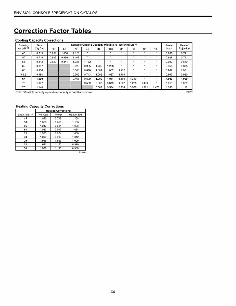
36
ENVISION CONSOLE SPECIFICATION CATALOG
Correction Factor Tables
Heating Capacity CorrectionsHeating Corrections
Ent Air DB °F Htg Cap Power Heat of Ext
45 1.050 0.749 1.158
50 1.059 0.859 1.130
55 1.043 0.894 1.096
60 1.033 0.947 1.064
65 1.023 0.974 1.030
68 1.009 0.990 1.012
70 1.000 1.000 1.000
75 1.011 1.123 0.970
80 1.000 1.196 0.930
7/20/06
Cooling Capacity CorrectionsEntering Total Sensible Cooling Capacity Multipliers - Entering DB ºF Power Heat of
Air WB ºF Clg Cap 60 65 70 75 80 80.6 85 90 95 100 Input Rejection
45 0.719 0.891 1.058 1.128 * * * * * * * 0.898 0.741
50 0.719 0.893 0.980 1.106 * * * * * * * 0.898 0.741
55 0.812 0.629 0.844 1.026 1.172 * * * * * * 0.922 0.819
60 0.897 0.820 0.995 1.206 1.238 * * * * 0.955 0.895
65 0.960 0.568 0.810 1.004 1.052 1.227 * * * 0.982 0.951
66.2 0.984 0.505 0.743 1.002 1.027 1.151 * * * 0.993 0.980
67 1.000 0.463 0.699 1.000 1.011 1.101 1.310 * * 1.000 1.000
70 1.047 0.599 0.865 0.879 1.007 1.225 1.433 * 1.018 1.029
75 1.148 0.567 0.584 0.734 0.956 1.261 1.476 1.056 1.118
Note: * Sensible capacity equals total capacity at conditions shown. 7/20/06
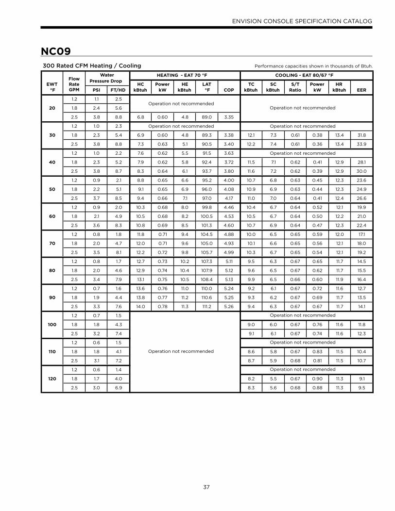
37
ENVISION CONSOLE SPECIFICATION CATALOG
300 Rated CFM Heating / Cooling Performance capacities shown in thousands of Btuh.
HEATING - EAT 70 °F COOLING - EAT 80/67 °F
EWTPressure Drop
HC Power HE LAT TC SC S/T Power HR °F PSI FT/HD kBtuh kW kBtuh °F COP kBtuh kBtuh Ratio kW kBtuh EER
1.2 1.1 2.5
20 1.8 2.4 5.6
2.5 3.8 8.8 6.8 0.60 4.8 89.0 3.35
1.2 1.0 2.3
30 1.8 2.3 5.4 6.9 0.60 4.8 89.3 3.38 12.1 7.3 0.61 0.38 13.4 31.8
2.5 3.8 8.8 7.3 0.63 5.1 90.5 3.40 12.2 7.4 0.61 0.36 13.4 33.9
1.2 1.0 2.2 7.6 0.62 5.5 91.5 3.63
40 1.8 2.3 5.2 7.9 0.62 5.8 92.4 3.72 11.5 7.1 0.62 0.41 12.9 28.1
2.5 3.8 8.7 8.3 0.64 6.1 93.7 3.80 11.6 7.2 0.62 0.39 12.9 30.0
1.2 0.9 2.1 8.8 0.65 6.6 95.2 4.00 10.7 6.8 0.63 0.45 12.3 23.6
50 1.8 2.2 5.1 9.1 0.65 6.9 96.0 4.08 10.9 6.9 0.63 0.44 12.3 24.9
2.5 3.7 8.5 9.4 0.66 7.1 97.0 4.17 11.0 7.0 0.64 0.41 12.4 26.6
1.2 0.9 2.0 10.3 0.68 8.0 99.8 4.46 10.4 6.7 0.64 0.52 12.1 19.9
60 1.8 2.1 4.9 10.5 0.68 8.2 100.5 4.53 10.5 6.7 0.64 0.50 12.2 21.0
2.5 3.6 8.3 10.8 0.69 8.5 101.3 4.60 10.7 6.9 0.64 0.47 12.3 22.4
1.2 0.8 1.8 11.8 0.71 9.4 104.5 4.88 10.0 6.5 0.65 0.59 12.0 17.1
70 1.8 2.0 4.7 12.0 0.71 9.6 105.0 4.93 10.1 6.6 0.65 0.56 12.1 18.0
2.5 3.5 8.1 12.2 0.72 9.8 105.7 4.99 10.3 6.7 0.65 0.54 12.1 19.2
1.2 0.8 1.7 12.7 0.73 10.2 107.3 5.11 9.5 6.3 0.67 0.65 11.7 14.5
80 1.8 2.0 4.6 12.9 0.74 10.4 107.9 5.12 9.6 6.5 0.67 0.62 11.7 15.5
2.5 3.4 7.9 13.1 0.75 10.5 108.4 5.13 9.9 6.5 0.66 0.60 11.9 16.4
1.2 0.7 1.6 13.6 0.76 11.0 110.0 5.24 9.2 6.1 0.67 0.72 11.6 12.7
90 1.8 1.9 4.4 13.8 0.77 11.2 110.6 5.25 9.3 6.2 0.67 0.69 11.7 13.5
2.5 3.3 7.6 14.0 0.78 11.3 111.2 5.26 9.4 6.3 0.67 0.67 11.7 14.1
1.2 0.7 1.5
100 1.8 1.8 4.3 9.0 6.0 0.67 0.76 11.6 11.8
2.5 3.2 7.4 9.1 6.1 0.67 0.74 11.6 12.3
1.2 0.6 1.5
110 1.8 1.8 4.1 8.6 5.8 0.67 0.83 11.5 10.4
2.5 3.1 7.2 8.7 5.9 0.68 0.81 11.5 10.7
1.2 0.6 1.4
120 1.8 1.7 4.0 8.2 5.5 0.67 0.90 11.3 9.1
2.5 3.0 6.9 8.3 5.6 0.68 0.88 11.3 9.5
Operation not recommended
Operation not recommended
Water
Operation not recommendedOperation not recommended
Operation not recommended
Operation not recommended
Operation not recommended
Operation not recommended
Operation not recommended
FlowRateGPM
NC09
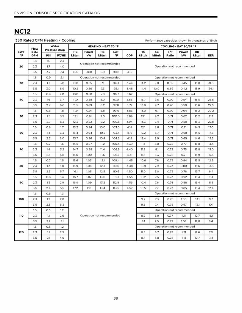
38
ENVISION CONSOLE SPECIFICATION CATALOG
350 Rated CFM Heating / Cooling Performance capacities shown in thousands of Btuh.
HEATING - EAT 70 °F COOLING - EAT 80/67 °F
EWTPressure Drop
HC Power HE LAT TC SC S/T Power HR °F PSI FT/HD kBtuh kW kBtuh °F COP kBtuh kBtuh Ratio kW kBtuh EER
1.5 1.0 2.3
20 2.3 1.7 4.0
3.5 3.2 7.4 8.6 0.80 5.9 90.8 3.15
1.5 0.9 2.1
30 2.3 1.7 3.8 10.0 0.85 7.1 94.3 3.44 14.2 9.8 0.69 0.45 15.8 31.6
3.5 3.0 6.9 10.2 0.86 7.3 95.1 3.48 14.4 10.0 0.69 0.42 15.9 34.1
1.5 0.9 2.0 10.8 0.88 7.8 96.7 3.62
40 2.3 1.6 3.7 11.0 0.88 8.0 97.0 3.66 13.7 9.5 0.70 0.54 15.5 25.5
3.5 2.9 6.6 11.3 0.89 8.2 97.8 3.72 13.9 9.7 0.70 0.50 15.6 27.6
1.5 0.8 1.8 11.9 0.91 8.8 99.6 3.86 13.0 9.1 0.70 0.64 15.2 20.2
50 2.3 1.5 3.5 12.1 0.91 9.0 100.0 3.89 13.1 9.2 0.71 0.62 15.2 21.1
3.5 2.7 6.2 12.3 0.92 9.2 100.6 3.94 13.3 9.4 0.71 0.58 15.3 22.8
1.5 0.8 1.7 13.2 0.94 10.0 103.0 4.14 12.1 8.6 0.71 0.71 14.5 17.0
60 2.3 1.4 3.3 13.4 0.94 10.2 103.4 4.16 12.2 8.7 0.71 0.68 14.5 17.8
3.5 2.6 6.0 13.7 0.96 10.4 104.2 4.19 12.4 8.9 0.71 0.65 14.6 19.2
1.5 0.7 1.6 14.5 0.97 11.2 106.4 4.39 11.1 8.0 0.72 0.77 13.8 14.4
70 2.3 1.4 3.2 14.7 0.98 11.4 106.9 4.40 11.3 8.1 0.72 0.75 13.8 15.0
3.5 2.5 5.8 15.0 1.00 11.6 107.7 4.41 11.5 8.3 0.72 0.71 13.9 16.3
1.5 0.7 1.5 15.6 1.03 12.1 109.4 4.45 10.6 7.8 0.73 0.84 13.5 12.6
80 2.3 1.3 3.0 15.9 1.04 12.3 110.0 4.48 10.9 7.9 0.73 0.80 13.6 13.5
3.5 2.5 5.7 16.1 1.05 12.5 110.6 4.50 11.0 8.0 0.73 0.78 13.7 14.1
1.5 0.6 1.4 16.7 1.07 13.0 112.1 4.55 10.2 7.5 0.73 0.92 13.4 11.1
90 2.3 1.3 2.9 16.9 1.09 13.2 112.8 4.56 10.4 7.6 0.74 0.88 13.4 11.8
3.5 2.4 5.5 17.2 1.10 13.4 113.5 4.57 10.5 7.7 0.73 0.85 13.4 12.4
1.5 0.6 1.3
100 2.3 1.2 2.8 9.7 7.3 0.75 1.00 13.1 9.7
3.5 2.3 5.3 9.8 7.4 0.75 0.97 13.1 10.1
1.5 0.5 1.2
110 2.3 1.1 2.6 8.9 6.9 0.77 1.11 12.7 8.1
3.5 2.2 5.1 9.1 7.0 0.77 1.08 12.8 8.4
1.5 0.5 1.2
120 2.3 1.1 2.5 8.5 6.7 0.79 1.21 12.6 7.0
3.5 2.1 4.9 8.7 6.8 0.78 1.18 12.7 7.4
Operation not recommended
Operation not recommended
Operation not recommended
Operation not recommended
Operation not recommended
Operation not recommended
Water
Operation not recommendedOperation not recommended
Operation not recommended
FlowRateGPM
NC12
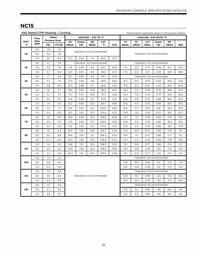
39
ENVISION CONSOLE SPECIFICATION CATALOG
450 Rated CFM Heating / Cooling Performance capacities shown in thousands of Btuh.
FlowRateGPM
HEATING - EAT 70 °F COOLING - EAT 80/67 °F
EWTPressure Drop
HC Power HE LAT TC SC S/T Power HR °F PSI FT/HD kBtuh kW kBtuh °F COP kBtuh kBtuh Ratio kW kBtuh EER
2.0 1.8 4.1
20 3.0 3.4 7.8
4.5 5.9 13.6 10.7 0.93 7.5 90.0 3.37
2.0 1.7 3.9
30 3.0 3.3 7.6 11.8 0.95 8.5 92.2 3.62 17.1 12.2 0.71 0.48 18.7 35.6
4.5 5.7 13.2 12.3 0.97 9.0 93.3 3.72 17.3 12.4 0.71 0.45 18.9 38.4
2.0 1.7 3.8 12.7 0.95 9.4 94.1 3.93
40 3.0 3.2 7.5 12.9 0.96 9.6 94.6 3.94 16.7 12.0 0.72 0.60 18.8 27.8
4.5 5.6 12.9 13.4 0.98 10.1 95.6 4.02 17.0 12.2 0.72 0.57 18.9 30.0
2.0 1.6 3.7 13.9 0.95 10.6 96.5 4.27 16.2 11.7 0.72 0.75 18.8 21.5
50 3.0 3.2 7.3 14.1 0.97 10.8 97.1 4.28 16.4 11.8 0.72 0.72 18.8 22.6
4.5 5.5 12.7 14.6 0.99 11.2 97.9 4.31 16.6 12.0 0.72 0.68 18.9 24.4
2.0 1.6 3.6 15.2 0.96 12.0 99.4 4.66 15.5 11.4 0.74 0.84 18.3 18.3
60 3.0 3.1 7.1 15.6 0.97 12.2 100.0 4.69 15.6 11.5 0.74 0.81 18.4 19.2
4.5 5.4 12.5 16.1 1.00 12.7 101.0 4.72 15.9 11.8 0.74 0.77 18.5 20.7
2.0 1.5 3.5 16.6 0.96 13.3 102.2 5.05 14.7 11.1 0.76 0.94 17.9 15.7
70 3.0 3.0 7.0 17.0 0.98 13.7 103.0 5.08 14.9 11.3 0.76 0.90 18.0 16.5
4.5 5.3 12.2 17.6 1.00 14.1 104.1 5.12 15.2 11.5 0.76 0.86 18.1 17.8
2.0 1.5 3.4 18.3 1.03 14.8 105.7 5.22 14.2 10.9 0.77 1.00 17.6 14.1
80 3.0 3.0 6.8 18.6 1.04 15.1 106.3 5.24 14.5 11.1 0.77 0.96 17.7 15.1
4.5 5.2 12.0 18.9 1.05 15.3 106.8 5.26 14.7 11.2 0.76 0.93 17.8 15.8
2.0 1.4 3.2 19.6 1.07 15.9 108.3 5.35 13.7 10.6 0.77 1.08 17.4 12.7
90 3.0 2.9 6.7 19.9 1.09 16.2 108.9 5.36 13.9 10.8 0.78 1.03 17.4 13.5
4.5 5.1 11.8 20.2 1.10 16.4 109.5 5.38 14.1 10.9 0.77 1.00 17.5 14.1
2.0 1.4 3.1
100 3.0 2.8 6.5 13.4 10.5 0.78 1.14 17.3 11.8
4.5 5.0 11.6 13.6 10.6 0.78 1.10 17.3 12.3
2.0 1.3 3.0
110 3.0 2.8 6.4 12.8 10.1 0.79 1.23 17.0 10.4
4.5 4.9 11.3 13.0 10.3 0.79 1.20 17.1 10.8
2.0 1.3 2.9
120 3.0 2.7 6.2 11.3 9.2 0.81 1.39 16.0 8.1
4.5 4.8 11.1 11.5 9.3 0.81 1.35 16.1 8.5
Operation not recommended
Operation not recommended
Water
Operation not recommendedOperation not recommended
Operation not recommended
Operation not recommended
Operation not recommended
Operation not recommended
Operation not recommended
NC15
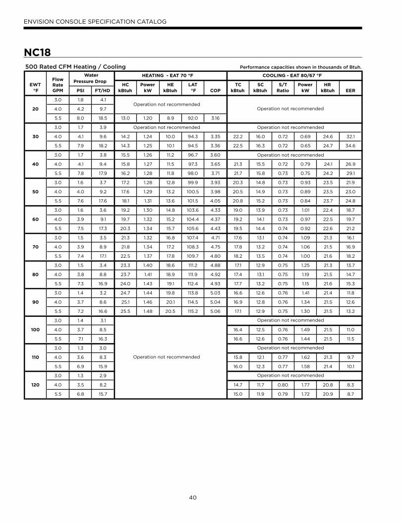
40
ENVISION CONSOLE SPECIFICATION CATALOG
500 Rated CFM Heating / Cooling Performance capacities shown in thousands of Btuh.
HEATING - EAT 70 °F COOLING - EAT 80/67 °F
EWTPressure Drop
HC Power HE LAT TC SC S/T Power HR °F PSI FT/HD kBtuh kW kBtuh °F COP kBtuh kBtuh Ratio kW kBtuh EER
3.0 1.8 4.1
20 4.0 4.2 9.7
5.5 8.0 18.5 13.0 1.20 8.9 92.0 3.16
3.0 1.7 3.9
30 4.0 4.1 9.6 14.2 1.24 10.0 94.3 3.35 22.2 16.0 0.72 0.69 24.6 32.1
5.5 7.9 18.2 14.3 1.25 10.1 94.5 3.36 22.5 16.3 0.72 0.65 24.7 34.6
3.0 1.7 3.8 15.5 1.26 11.2 96.7 3.60
40 4.0 4.1 9.4 15.8 1.27 11.5 97.3 3.65 21.3 15.5 0.72 0.79 24.1 26.9
5.5 7.8 17.9 16.2 1.28 11.8 98.0 3.71 21.7 15.8 0.73 0.75 24.2 29.1
3.0 1.6 3.7 17.2 1.28 12.8 99.9 3.93 20.3 14.8 0.73 0.93 23.5 21.9
50 4.0 4.0 9.2 17.6 1.29 13.2 100.5 3.98 20.5 14.9 0.73 0.89 23.5 23.0
5.5 7.6 17.6 18.1 1.31 13.6 101.5 4.05 20.8 15.2 0.73 0.84 23.7 24.8
3.0 1.6 3.6 19.2 1.30 14.8 103.6 4.33 19.0 13.9 0.73 1.01 22.4 18.7
60 4.0 3.9 9.1 19.7 1.32 15.2 104.4 4.37 19.2 14.1 0.73 0.97 22.5 19.7
5.5 7.5 17.3 20.3 1.34 15.7 105.6 4.43 19.5 14.4 0.74 0.92 22.6 21.2
3.0 1.5 3.5 21.3 1.32 16.8 107.4 4.71 17.6 13.1 0.74 1.09 21.3 16.1
70 4.0 3.9 8.9 21.8 1.34 17.2 108.3 4.75 17.8 13.2 0.74 1.06 21.5 16.9
5.5 7.4 17.1 22.5 1.37 17.8 109.7 4.80 18.2 13.5 0.74 1.00 21.6 18.2
3.0 1.5 3.4 23.3 1.40 18.6 111.2 4.88 17.1 12.9 0.75 1.25 21.3 13.7
80 4.0 3.8 8.8 23.7 1.41 18.9 111.9 4.92 17.4 13.1 0.75 1.19 21.5 14.7
5.5 7.3 16.9 24.0 1.43 19.1 112.4 4.93 17.7 13.2 0.75 1.15 21.6 15.3
3.0 1.4 3.2 24.7 1.44 19.8 113.8 5.03 16.6 12.6 0.76 1.41 21.4 11.8
90 4.0 3.7 8.6 25.1 1.46 20.1 114.5 5.04 16.9 12.8 0.76 1.34 21.5 12.6
5.5 7.2 16.6 25.5 1.48 20.5 115.2 5.06 17.1 12.9 0.75 1.30 21.5 13.2
3.0 1.4 3.1
100 4.0 3.7 8.5 16.4 12.5 0.76 1.49 21.5 11.0
5.5 7.1 16.3 16.6 12.6 0.76 1.44 21.5 11.5
3.0 1.3 3.0
110 4.0 3.6 8.3 15.8 12.1 0.77 1.62 21.3 9.7
5.5 6.9 15.9 16.0 12.3 0.77 1.58 21.4 10.1
3.0 1.3 2.9
120 4.0 3.5 8.2 14.7 11.7 0.80 1.77 20.8 8.3
5.5 6.8 15.7 15.0 11.9 0.79 1.72 20.9 8.7
Operation not recommended
Operation not recommended
Operation not recommended
Operation not recommended
Operation not recommended
Operation not recommended
Water
Operation not recommendedOperation not recommended
Operation not recommended
FlowRateGPM
NC18
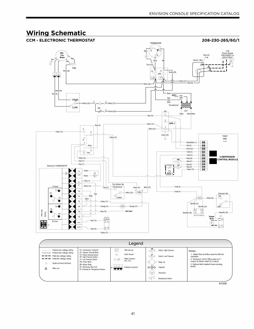
41
ENVISION CONSOLE SPECIFICATION CATALOG
CC
CCM – with Electronic Stat
Cap
Brn
WhtGrn
PSCFan
Motor
Factory low voltage wiring
Temperature Switch
Factory line voltage wiring
Quick connect terminal
Wire nut
Notes:1. Switch Red and Blue wires for 208 volt operationField low voltage wiring
Field line voltage wiring
LP
HP
Handi - Box
Ground Lug
HL
Cycled
Continuous
CCT2 T1
Compressor
C
R
S
Tan (33)
Red Blk
Blue
L1L2
High
Low
Auto
Fan
6
1
32
4
5
COMPRESSOR CONTROL MODULE
TESTPIN
HP
HP
CC
CG
LO
RC
LPLP
Y
HP
HP
CC
CG
LO
RC
LPLP
Y
Transformer
24V
Blue230V265V
Red208V
Black
Yellow Black/White
Black/White (1)
Red (2)
Brown (3)
Black (6)
Black (7)
Blue (8)Blue (9)
Ther
m istor
Electronic THERMOSTAT
T1
T3
B Cool
A Heat
T2
T4
T6
T5
SHUT
DOWN
24 V
AC
INPUT
T6
T4
T5
T2
T1
T3
Overide
Shut dow
n
J1
Black
Violet (5)
Violet (4)
Yellow (13)
Yellow (10)
White (20)
Orange (14) Orange (21)
Black (29)
Red (30)
Black
Black (12)
White (18)
Red (11)
Red (19)
Red (17)
24 V Accessory
24VACShutdown
Red (15)
Red (16)
NOTE 1
T
ST
CC - Compressor Contactor
HP - High Pressure SwitchLP - Low Pressure Switch
RV - Reversing Valve CoilST - Entering Air Temperature Sensor
RB - Blower Relay
Black
Black
Red (11)
Black (12)
Red (17)
Red (19)
Black (25)
White (28)
Black (31)Red (32)
Brown (26)
RB
4 2
5
Red
RV
DT
ON
OFF
Damper Sw
Damper Motor
D
Fan Mode Sw
Blk/Wht (24)
Blk/Wht (23)
Black (22)
White (18 )
Blue (T6)
NOTE 2
2. Terminal C of 24 V PB is used as “L”output for Brown wire 3 for Lockout.
31RB Violet (4)
Blue/Wht (36) Blue/Wht (35)
White (34)
Green (00)
FS
Yellow (13)
Not Used
Violet (5)
Yellow (13)
Yellow (10)
Legend
Console Unit – Wiring Schematic 208-230-265/60/1
6/10/08
Black (22)
White (28)
Black (27)
Brown (26)
DT - Damper Terminal Block
PB - Power Block
PB
1
2
3
Field wire lug
Earth Ground
Relay Contacts -N.O., N.C.
Polarized connector
132
P
Switch - High Pressure
Switch - Low Pressure
Relay coil
Capacitor
Thermistor
HP
LP
T
L1
NOTE 3
3. Optional field installed freeze sensing device.
FS - Freeze Sensing Device
G
UnitPower Supply
208-230/60/1 or265-277/60/1
Wiring Schematic CCM - ELECTRONIC THERMOSTAT 208-230-265/60/1
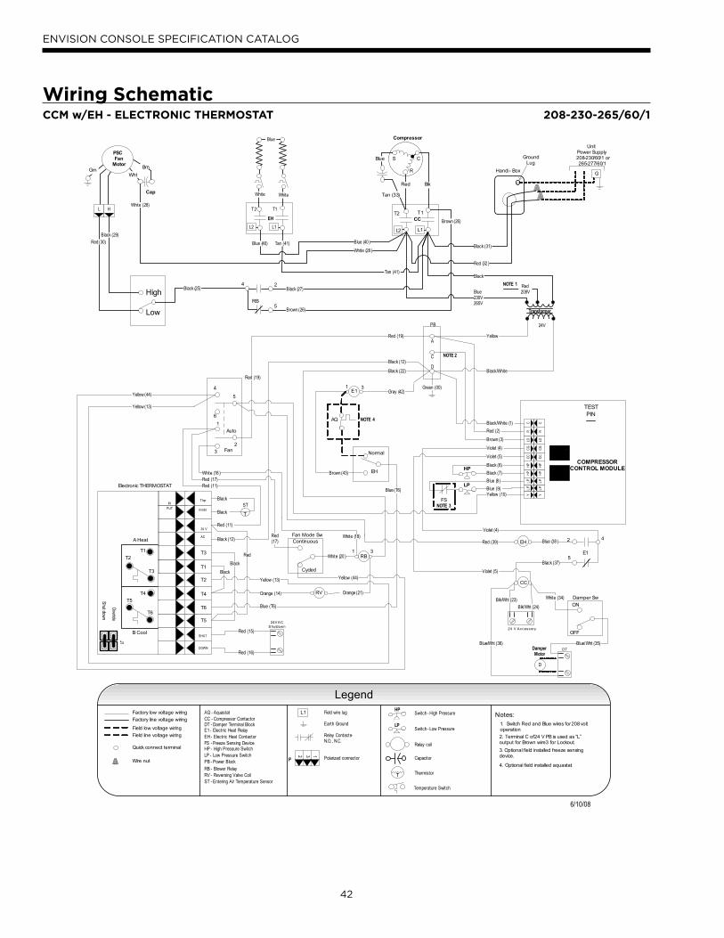
42
ENVISION CONSOLE SPECIFICATION CATALOGCCM – with Electric Heat and Electronic Stat
Console Unit – Wiring Schematic 208-230-265/60/1
24V
Transformer
EH
CC
Cap
Brn
WhtGrn
PSCFan
Motor
Legend
LP
HP
UnitPower Supply208-230/60/1 or265-277/60/1
GHandi - Box
Ground Lug
HL
Cycled
Continuous
CCT2 T1
Compressor
C
R
S
Tan (33)
Red Blk
Blue
L1L2
High
Low
Auto
Fan
6
1
3
2
4
5
COMPRESSOR CONTROL MODULE
TESTPIN
HP
HP
CC
CG
LOR
CL
PL
PY
HP
HP
CC
CG
LOR
CL
PL
PY
Blue230V265V
Red208V
Black
Yellow
Black/White
Black/White (1)
Red (2)
Black (6)
Black (7)
Blue (8 )
Blue (9)
Ther
m istor
Electronic THERMOSTAT
T1
T3
B Cool
A Heat
T2
T4
T6
T5
SHUT
DOWN
24 V
AC
INPUT
T6
T4
T5
T2
T1
T3
Overide
Shut dow
n
J1
Black
Violet (5)
Yellow (13)
Yellow (10)
White (20 )
Orange (14) Orange (21)
Black (29)
Red (30)
PB
A
C
D
Black
Black (12)
White (18 )
Red (11)
Red (19)
Red (17)
24 V Accessory
24VACShutdown
Red (15)
Red (16)
NOTE 1
T
STBlack
Black
Red (11)
Black (12)
Red (17)
Red (19)
Black (25)
White (28)
Black (31)
Red (32 )
Brown (26)
Black (27)
RB
4 2
5
Red
EH
T2 T1
L2
WhiteWhite
L1
EH
Normal
RV
DT
ON
OFF
Damper Sw
Damper Motor
D
Fan Mode Sw4
5
2
E1
E1
AQ
Blk/Wht (24)
Blk/Wht (23)
Black (22)
White (18)
Blue (T6)
NOTE 2
31RB
31
Black (37)
Blue (38 )
Blue/Wht (36) Blue/Wht (35)
White (34)
Blue (T6)
FS
Yellow (44)
Yellow (44)
Brown (43)
Yellow (13)
Blue
Tan (41)Blue (40)
White (28 )
Blue (40 )
Brown (3)
Tan (41)
Brown (26)
Green (00)
Red (39)
Gray (42)
NOTE 3
NOTE 4
Violet (4)
Violet (4)
Violet (5)
Factory low voltage wiring
Temperature Switch
Factory line voltage wiring
Quick connect terminal
Wire nut
Notes:1. Switch Red and Blue wires for 208 volt operationField low voltage wiring
Field line voltage wiring
CC - Compressor Contactor
HP - High Pressure SwitchLP - Low Pressure Switch
RV - Reversing Valve CoilST - Entering Air Temperature Sensor
RB - Blower Relay
2. Terminal C of 24 V PB is used as “L”output for Brown wire 3 for Lockout.
Legend
DT - Damper Terminal Block
PB - Power Block
Field wire lug
Earth Ground
Relay Contacts -N.O., N.C.
Polarized connector
132
P
Switch - High Pressure
Switch - Low Pressure
Relay coil
Capacitor
Thermistor
HP
LP
T
L1
3. Optional field installed freeze sensing device.
FS - Freeze Sensing Device
4. Optional field installed aquastat.
AQ - Aquastat
EH - Electric Heat ContactorE1 - Electric Heat Relay
6/10/08
CCM w/EH - ELECTRONIC THERMOSTAT
Wiring Schematic208-230-265/60/1
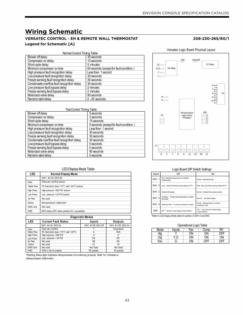
43
ENVISION CONSOLE SPECIFICATION CATALOG
Operational Logic TableModeHtgClg
Inputs Fan Comp RVY
Y,OFan G ON
ONON
OFFONON
OFFONOFF
SW1 - #4 On, SW2 OffDrain pan overflow lockout
FS thermistor ( loop <15°F, well < 30°F) lockoutHigh pressure >600 PSI lockout Low pressure < 40 PSI lockout Not usedMicroprocessor malfunction*Not UsedSW2 status (Off = down position, On = up position)
DrainWater Flow High PressLow PressAir FlowStatusDHW LimitHWD
LED Normal Display Mode
SW1- #4 On, SW2 OnDrain pan overflow FS thermistor (loop <15°F, well <30°F) High pressure > 600 PSI Low pressure < 40 PSINot usedNot usedNot usedSW2 in the On position
Current Fault StatusSW1- #4 Off, SW2 Off
YGO
ESNSLS
Not UsedOff position
Inputs
CompressorFANO
ESNSLS
Not UsedOn position
OutputsDiagnostic Modes
SW1- # 4 Off, SW2 OnDrainWater Flow High PressLow PressAir FlowStatusDHW LimitHWD
LED
LED Display Mode Table
CC RelayFan Relay
CCCCG
CC
RR
FAN FANCOM
R C Y O G LO ES NS LS
P3
P1
SW1MicroprocessorLogic Control17P529A01
P2
61
72
83
94
105
Versatec Logic Board Physical Layout
Switch OFF ON
SW1 - 1
SW1 - 2
SW1 - 3
SW1 - 4
SW1 - 5
SW2
Test - Selected timings sped up to facilitatetroubleshooting
Loop - Closed loop freeze sensing setting (15°F)
IO Display * - Enables Input/Output display on externalLED board*
Enables NS features
Motorized Valve - 1.5 minute compressor on delay
OFF * - Normal or Input display mode activatedON * - Current fault or Output displaymode activated
Normal - Standard timings
Well - Open loop freeze sensing setting (30°F)
Normal * - Unit status display
Normal - Standard thermostat operation
Normal - Standard delay on call fromcompressor used
*Refer to LED Display Mode table for position of SW1-4 and SW2
Logic Board DIP Switch Settings
Normal Control Timing TableBlower off delayCompressor on delayShort cycle delayMinimum compressor on timeHigh pressure fault recognition delayLow pressure fault recognition delay
Condensate overflow fault recognition delayLow pressure fault bypass delayFreeze sensing fault bypass delayMotorized valve delayRandom start delay
Freeze sensing fault recognition delay
30 seconds10 seconds5 minutes60 seconds (except for fault condition )Less than 1 second30 seconds30 seconds30 seconds2 minutes2 minutes90 seconds0 - 25 seconds
Test Control Timing TableBlower off delayCompressor on delayShort cycle delayMinimum compressor on timeHigh pressure fault recognition delayLow pressure fault recognition delay
Condensate overflow fault recognition delayLow pressure fault bypass delayFreeze sensing fault bypass delayMotorized valve delayRandom start delay
Freeze sensing fault recognition delay
5 seconds2 seconds15 seconds5 seconds (except for fault condition )Less than 1 second30 seconds30 seconds30 seconds0 seconds0 seconds90 seconds0 seconds
*Flashing Status light indicates microprocessor is functioning properly. Solid "on" indicates a microprocessor malfunction.
Wiring Schematic208-230-265/60/1VERSATEC CONTROL - EH & REMOTE WALL THERMOSTAT
Legend for Schematic [A]
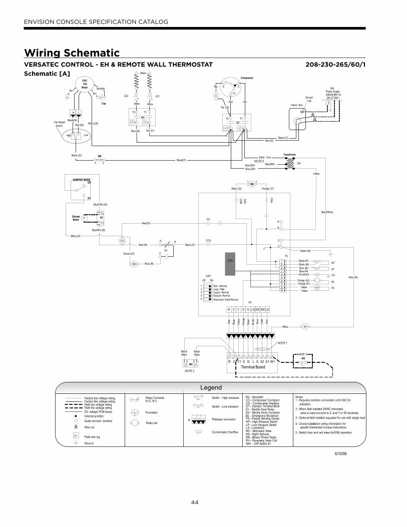
44
ENVISION CONSOLE SPECIFICATION CATALOG
Wiring Schematic208-230-265/60/1VERSATEC CONTROL - EH & REMOTE WALL THERMOSTAT
Schematic [A]
Transformer
24V
Cap
Brn/Wht
BrnGrn
H L
PSCFan
Motor
CC
T2 T1
Compressor
C
R
S
Tan (36)
Red
Blu
L1L 2
Relay Contacts-N.O., N.C.
Thermistor
Relay coil
Switch - High pressure
Switch - Low pressure
Polarized connector
Condensate Overflow
Factory low voltage wiringFactory line voltage wiringField low voltage wiringField line voltage wiring
Internal junction
Quick connect terminal
Wire nut
Field wire lug
Ground
L1
Legend
5 - Switch blue and red wires for 208V operation.
T
132
P
Notes:1 - Requires common connection or 24 VAC for activation.
NOTE 5Red 208V
Blue 230V
Blk
Black(27)
R
C
C
R
CC
CCG
OnOff
Test / NormalLoop / Well
P2
P1
SW1
Inputs / NormalOutputs / Normal
12345 Motorized Valve / Normal
FAN
FAN
CO
M
CPU
FS
LP
HP
RV
CO
LSNSESLOGOYCR
Yellow
Black/White
T
Black (47)162738495
10
DC voltage PCB traces
High Low
Fan SpeedSwitch
RB
Blue 265V
4 - Check installlation wiring information for specific thermostat hookup instructions.
RedBlack (25)
RB
Gray (42)
White (28)Black(29)
Red (30)
Damper Motor
Off
On
DAMPER MODE
DTD
Blue/Wht (35)
MV
Black (31)Red (32)
Handi - Box
Ground Lug
UnitPower Supply208-230 /60/1 or265-277/60/1
G
CR Y1 O G L S
Terminal BoardX2 X1 W1
Red
Blac
k
Yel
low
Ora
nge
Bro
wn
Gre
en
NOTE 2
Vio
let
Pin
k
Blue
1 3
4 2
NOTE 1
ES – Emergency Shutdown
Black/White
Black/White
Black Com
E1
EH
T2 T1
L1
WhiteWhite
L2
Blue (40)
LS1LS2
Black
Tan (41)
E1
4
2
5
Black (37)
Blue (38)
Red (39)
AQNOTE 3
White
2 - When field installed 24VAC motorized valve is used, connect to C and Y or SV terminals.
3 - Optional field installed aquastat for use with single heat
Blue/Wht (36)
Black (46)Blue (45 )Blue (44)Brown(43)
Orange (42)Orange (41 )
YellowYellow
Green (00)
Black (22) Orange (21)
EH
CC
White (34)
Brown (43)
Legend
Microprocessor – with Remote Wall Stat & Electric Heat
Console Unit – Wiring Schematic 208-230-265/60/1
97P786-04 6/10/08
EH – Electric Heat Contactor
AQ – AquastatCC – Compressor ContactorCO – Condensate Overflow
E1 – Electric Heat Relay
FS – Freeze Sensing DeviceHP – High Pressure SwitchLP – Low Pressure SwitchLS – Loadshed
NS – Night SetbackRB – Blower Power RelayRV – Reversing Valve CoilSW1 – DIP Switch #1
MV – Motorized Valve
Red(19)
DT – Damper Terminal Block
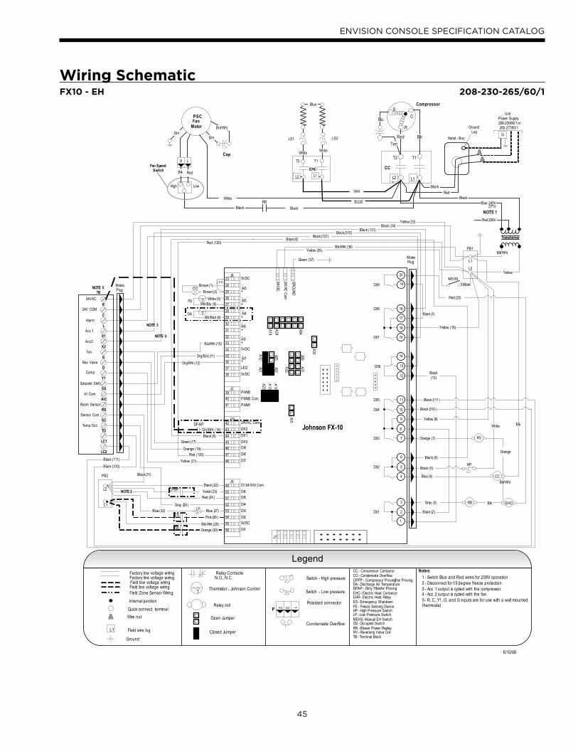
45
ENVISION CONSOLE SPECIFICATION CATALOG
Wiring SchematicFX10 - EH 208-230-265/60/1
Transformer
Blue 240V
Red 208V
Black
Blk/Wht
Black
DA T
HP
RB
RV
CC
NOTE 1277V
FS T
CO
Yellow
PB1
L1
L2
OS
NOTE 2 CP/FP
DF/AP
L1
L2
PB2
NOTE 3
NOTE 4
NOTE 5
Compressor
CC
T2
R
S
C
BlkRed
Tan
Blu
L2
T1
L1
Handi - Box
Ground Lug
UnitPower Supply208-230/60/1 or265-277/60/1
G
Black
Red
Cap
Brn/Wht
BrnGrn
H L
PSCFan
Motor
High Low
Fan SpeedSwitch
RB
ES
LP
11 K
Johnson FX-10
5VDC
AI3
23
24
25
26
27
28
29
30
31
32
33
34
35
36
37
38
+
-
AI5-
+
AI4-
+
AI6
AI2
AI1
5VDC
5VDC
LED
-
-
-
+
+
+
24VAC
24VAC
Com
GR
OU
ND
39
40
41
PWM2
PWM2 Com
PWM1
42
43
44
45
46
47
48
24VAC Com
DI12
DI11
DI10
DI9
DI8
DI7
49
50
51
52
53
54
55
56
DI 3/4 /5/6/ Com
DI6
DI5
DI4
DI3
DI2
DI1
9VDC
20
19
18
17
16
15
14
13
12
11
10
9
8
7
6
5
4
3
1
D09
D08
D07
D06
D05
D04
D03
D02
D01
J8
J2
J10
J9
J7
A32
A31
A35
A14
A24
A34
A33
A15
TThermistor - Johnson Control
Relay coil
Switch - High pressure
Switch - Low pressure
Polarized connector
Condensate Overflow
132
P
Factory low voltage wiringFactory line voltage wiringField low voltage wiringField line voltage wiring
Internal junction
Quick connect terminal
Wire nut
Field wire lug
Ground
Notes:
L1
1 - Switch Blue and Red wires for 208V operation Relay Contacts-
N.O., N.C.2 - Disconnect for 15 degree freeze protection
Field Zone Sensor Wiring3 - Acc 1 output is cycled with the compressor.4 - Acc 2 output is cycled with the fan.5 - R, C, Y1, O, and G inputs are for use with a wall mounted thermostat.
A23
A13
A11
A21A
12
A25A22
Open Jumper
Closed Jumper
2
TB
R
C
Y1
O
G
L
X1
X2
24VAC
24V COM
Alarm
Acc 1
Acc 2
Fan
Rev Valve
Comp
SS
AIC
RS
SC
TO
Setpoint Shift
AI Com
Room Sensor
Sensor Com
Temp Occ
EHC
T2 T1
L1L2
Blue
WhiteWhite
LS1 LS2
Black (6)
Blue (4)
MEHS
EHC
MolexPlug
White
Black
Blk/Red (9)
White (5)Wht/Blu (6)
Brown (2)
Black (22)
Blk/Wht (29)
Blue (27)Blue (32)
Yellow (35)Blk/Wht (36)
Black (6)
Black (6)
Yellow (33)Black (34)
Black(121)Black (515)
Black (131)
Brown (1)
Gry/Wht (14)
Orange (30)
Pink (28 )
Red (24 )
Violet (23)
Black (31)
Green (37)
Yellow
Yellow (16)
Red (20)
Black (1)
Black (2 )
Orange (7)
Black (12)
Gray (3)
Black (5)
Yellow (9)
Black (310 )
Black (111 )
Blk Red
LC1
LC2
MolexPlug
TAN
BLUE
Blk
Blk
Blk/Wht
Orange
White
Black (310)
Black (111)
Gray (26 )
Org/Wht (12)
Org/Bck (11)
Blu/Wht (10)
Yellow (21)
Orange (19)
Green (17)
Red (120)
Red (120)
FX10 – with Electric Heat
Console Unit – Wiring Schematic 208-230-265/60/1 97PXXX -XX
LegendCC - Compressor ContactorCO - Condensate OverflowCP/FP - Compressor Proving/Fan ProvingDA - Discharge Air TemperatureDF/AP - Dirty Filter/Air ProvingEHC - Electric Heat ContactorEHR - Electric Heat RelayES - Emergency ShutdownFS - Freeze Sensing DeviceHP - High Pressure SwitchLP - Low Pressure SwitchMEHS - Manual EH SwitchOS - Occupied SwitchRB - Blower Power ReplayRV - Reversing Valve CoilTB - Terminal Block
6/10/08
46
ENVISION CONSOLE SPECIFICATION CATALOG
Engineering Guide Specifications
GeneralFurnish and install WaterFurnace Water Source Heat
Pumps, as indicated on the plans. Equipment shall be
completely assembled, piped and internally wired. Chassis
shall be installed with factory built cabinet or other custom
cabinet approved by WaterFurnace engineering. Chassis
SHALL NOT be installed without an approved cabinet
enclosure. Capacities and characteristics as listed in the
schedule and the specifications that follow. The reverse
cycle heating/cooling units shall be floor mounted console
type with horizontal air inlet and up-flow air discharge.
Units shall be ARI/ISO 13256-1 certified and listed by
a nationally recognized safety-testing laboratory or
agency, such as ETL Testing Laboratory. Each unit shall be
computer run-tested at the factory with conditioned water
and operation verified to catalog data. Each unit shall be
mounted on a pallet and shipped in a corrugated box or
stretch-wrapped. The units shall be designed to operate
with entering liquid temperature between 20°F and 120°F
[-6.7°C and 48.9°C].
Chassis & Cabinet
The cabinet shall be fabricated from heavy-gauge
galvanized steel and finished with a beige textured epoxy
powder coating on both sides for added protection. This
corrosion protection system shall meet the stringent 1000
hour salt spray test per ASTM B117.
The cabinet shall be easily removable to allow for ease
of service to the controls compartment, chassis, and
piping. The top of the cabinet and grille is a horizontally
flat (optional sloped) surface with a hinged control door
cover. The return air filter shall be 1” (25.4 mm) fiberglass
disposable type media.
The return and supply air sections are insulated with a
1/4” (6.4 mm) thick, dual density, 2 lb/ft3 (32 kg/m3)
coated mat glass fiber with edges sealed or tucked under
flanges to prevent the introduction of glass fibers into
the discharge supply air through the aluminum grille.
Standard cabinet panel insulation must meet NFPA 90A
requirements, air erosion and mold growth limits of UL-
181, stringent fungal resistance test per ASTM-C1071 and
ASTM G21, and shall meet zero level bacteria growth per
ASTM G22. Unit insulation must meet these stringent
requirements or unit(s) will not be accepted.
Option: A Super Quiet Sound package shall include multi-
density full coverage compressor blanket.
Option: Shipped with motorized outside air damper and damper assembly for 25% make-up air.
The drain pan shall be of stainless steel construction to
inhibit corrosion and bacterial growth. Drain outlet shall
be located on pan as to allow complete and unobstructed
drainage of condensate. The unit as standard will be
supplied with solid-state electronic condensate overflow
protection with microprocessor or FX10 option. Mechanical
float switches WILL NOT be accepted. Condensate tube
shall be constructed of stainless steel and have an internal
factory installed condensate trap.
Refrigerant Circuit
All units shall utilize the non-ozone depleting and low
global warming potential refrigerant R410A. All units shall
contain a sealed refrigerant circuit including a hermetic
motor-compressor, bi-directional thermostatic expansion
valve, finned tube air-to-refrigerant heat exchanger,
reversing valve, coaxial tube water-to-refrigerant heat
exchanger, and service ports.
Compressors shall be high-efficiency single speed rotary
type designed for heat pump duty and mounted on
durometer grommets to provide vibration free compressor
mounting. Compressor motors shall be single-phase PSC
with external overload protection.
The air coil shall be sized for low-face velocity and
constructed of lanced aluminum fins bonded to rifled
copper tubes in a staggered pattern not less than three
rows deep for enhanced performance.
Option: FormiShieldTM air coil coating for maximum
protection against formicary corrosion.
The coaxial water-to-refrigerant heat exchanger shall be
designed for low water pressure drop and constructed of
a convoluted copper (cupronickel option) inner tube and
a steel outer tube. Refrigerant to air heat exchangers shall
utilize enhanced corrugated lanced aluminum fins and
rifled copper tube construction rated to withstand 600
PSIG (4135 kPa) refrigerant working pressure. Refrigerant
to
water heat exchangers shall be of copper inner water tube
and steel refrigerant outer tube design, rated to withstand
600 PSIG (4135 kPa) working refrigerant pressure and 450
PSIG (3101 kPa) working water pressure. The thermostatic
expansion valve shall provide proper superheat over the
entire liquid temperature range with minimal “hunting.”
The valve shall operate bi-directionally without the use of
check valves.
Option: Cupro-nickel refrigerant to water heat exchanger shall be of copper-nickel inner water tube and steel
refrigerant outer tube design, rated to withstand 600 PSIG
(4135 kPa) working refrigerant pressure and 450 PSIG
(3101 kPa) working water pressure. Water lines shall also be
of cupronickel construction.
47
ENVISION CONSOLE SPECIFICATION CATALOG
Option: ThermaShield coated water-to-refrigerant heat exchanger, water lines and refrigerant suction lines shall be insulated to prevent condensation at low liquid
temperatures below 50°F.
Fan Motor & Assembly
The fan shall be a direct drive centrifugal type with a twin
dynamically balanced wheel. The housing and wheel shall
be designed for quiet, low outlet velocity operation. The
fan housing shall be constructed of galvanized steel and
shall be removable from the unit for servicing of the fan
motor. The fan motor shall be a two-speed type and shall
be isolated from the housing by rubber grommets. The
motor shall be permanently lubricated and have thermal
overload protection.
ElectricalA control box shall be located within the unit compressor compartment and shall contain a 75VA transformer, 24 Volt activated, 2 pole compressor contactor, and solid-state controller for complete unit operation. Units shall be name-plated for use with time delay fuses or HACR circuit breakers. Unit controls shall be 24 Volt and provide heating or cooling as required by the remote thermostat/sensor.
Unit mounted controls shall consist of switches for “OFF”,
“FAN”, and “AUTO” or “HEAT/COOL”. An additional
switch is provided for fan speed setting of “HI” or “LO”.
The unit shall be equipped with a fan switch on the side
of the control to provide “CONTINUOUS” or “CYCLED”
fan operation. “CYCLED” fan will turn the fan on with the
compressor. A unit-mounted electronic thermostat with
a remote electronic thermistor located in the return air
will control compressor operation in heating and cooling
modes. Unit mounted thermostat shall be the standard
thermostat option. All unit mounted thermostats shall
be auto changeover. Manual changeover WILL NOT be
accepted. Electro-mechanical operation WILL NOT be
accepted.
ControlsStandard: A compressor control module (CCM) shall be
included to disable compressor operation in the event of
a trip of any of the safety switches and to send a signal
to activate a fault indicator light at the thermostat. The
CCM shall be capable of being reset from the thermostat
or from the unit main disconnect switch. A terminal block
with screw terminals shall be provided for field connection of all low-voltage wiring.
Option: Versatec microprocessor-based controller will
provide operational sequencing; high and low pressure
switch monitoring, freeze sensing, lockout mode control,
emergency shutdown mode, random start, short cycle
protection, LED mode and fault indicators, fault memory,
input and output diagnostics, and field selectable options,
and condensate overflow sensing.
Option: FX10 microprocessor-based controller that
interfaces with an electronic thermostat to monitor
and control unit operation. The control shall provide
operational sequencing, fan speed control, high, low
and loss of charge pressure monitoring, freeze sensing,
condensate overflow sensing, lockout mode control,
fault memory, field selectable options. The control shall
communicate all mode, status, fault and lockout codes
to the front end system for fast and accurate equipment
diagnosis. The control shall provide fault retry three times
before locking out to limit nuisance trips.
Optional FX10 microprocessor control communication protocols: N2, LonWorks, or BACnet
Option: Remote mounted thermostat is available for CCM
& Versatec (standard with FX10 option). A terminal block
with screw terminals will be provided for field control
wiring.
Piping
Supply and return water connections shall be 1/2 in. [12.7
mm] FPT copper threaded fittings. All water piping
shall be insulated to prevent condensation at low liquid
temperatures.
A stainless steel tube stubbed out from the chassis is
provided for condensate drain attachment. A short piece
of polyvinyl hose is supplied to assist in adapting to drain.
Accessories Hose Kits – Ball Valves (field-installed)
A flexible steel braid hose featuring Kevlar® reinforced
EPDM core with ANSI 302/304 stainless steel outer braid
and fire rated materials per ASTM E 84-00 (NFPA 255,
ANSI/UL 723 & UBC 8-1). Ball valve at one end; swivel
connector with adapter at the other end (swivel to adapter
connection via fiber or EPDM gasket). Swivel connection
provides union between heat pump and piping system. The
hoses feature brass fittings, stainless steel ferrules. A fullport ball valve shall be provided with integral P/T (pressure/temperature) port on supply hose. Specifications: Temperature range of 35°F [2°C] to 180°F [82°C]. Max. working pressure of 400 psi [2757 kPa] for 1/2˝ and 3/4˝ hose kits; max. working pressure of 350 psi [kPa] for 1˝ and 1-1/4˝ hose kits.
Hose Kits – Automatic Balancing and Ball Valves (field-installed)
A flexible steel braid hose featuring Kevlar® reinforced
EPDM core with ANSI 302/304 stainless steel outer braid
and fire rated materials per ASTM E 84-00 (NFPA 255,
Engineering Guide Specifications
48
ENVISION CONSOLE SPECIFICATION CATALOG
ANSI/UL 723 & UBC 8-1). Ball valve at one end; swivel
connector with adapter at the other end (swivel to adapter
connection via fiber or EPDM gasket). Swivel connection
provides union between heat pump and piping system.
The hoses feature brass fittings, stainless steel ferrules.
A full port ball valve shall be provided with integral P/T
(pressure/temperature) port on supply hose and automatic
balancing valve with integral P/T ports and full port ball
valve on return hose. Specifications:
Temperature range of 35°F [2°C] to 180°F [82°C].•
Max. working pressure of 400 psi [2757 kPa] for 1/2˝ •
and 3/4˝ hose kits; max. working pressure of 350 psi
[2413 kPa] for 1˝ and 1-1/4˝ hose kits.
Minimum burst pressure of four times working pressure.•
Hose Kits – Automatic Balancing and Ball Valves with ‘Y’ strainer (field-installed)
A flexible steel braid hose featuring Kevlar® reinforced
EPDM core with ANSI 302/304 stainless steel outer braid
and fire rated materials per ASTM E 84-00 (NFPA 255,
ANSI/UL 723 & UBC 8-1). Ball valve at one end; swivel
connector with adapter at the other end (swivel to adapter
connection via fiber or EPDM gasket). Swivel connection
provides union between heat pump and piping system. The
hoses feature brass fittings, stainless steel ferrules. A “y”
strainer is provided on one end for fluid straining andintegral “blowdown” valve.. A full port ball valve shall be provided with integral P/T (pressure/temperature) port on supply hose and automatic balancing valve with integral P/T ports and full port ball valve on return hose. Specifications:
Temperature range of 35°F [2°C] to 180°F [82°C].•
Max. working pressure of 400 psi [2757 kPa] for 1/2˝ •
and 3/4˝ hose kits; max. working pressure of 350 psi
[2413 kPa] for 1˝ and 1-1/4˝ hose kits.
Minimum burst pressure of four times working pressure.•
Auxiliary Heater (field-installed 208-230V units only)
An electric resistance heater shall provide supplemental
and/or emergency heating capability. A manual switch
shall be mounted on the side of the control compartment
with “NORMAL” or “BOILERLESS” mode. “NORMAL” will
run the compressor when there is a call for heating or
cooling. “BOILERLESS” mode operation will run electric
heat whenever there is a call for heating and run the
compressor for a cooling call.
Engineering Guide Specifications

Product: Envision Series Console
Type: Geothermal/Water Source Heat Pumps
Size: 0.75-1.5 Ton
Document: Specification Catalog
Manufactured by
WaterFurnace International, Inc.
9000 Conservation Way
Fort Wayne, IN 46809
www.waterfurnace.com
© WaterFurnace International, Inc., 9000 Conservation Way, Fort Wayne, IN 46809-9794. WaterFurnace has a policy of
continual product research and development and reserves the right to change design and specifications without notice.
SC1010CN


![Envision Low Sill Console Installation Manual · ENVISION LOW SILL CONSOLE INSTALLATION MANUAL Model Console 09 12 15 18 Compressor (1 each) Rotary Factory Charge R-410A, oz [kg]](https://img.pdfslide.us/doc/110x75/5eaab4b6c0d1a85e8d3cca45/envision-low-sill-console-installation-manual-envision-low-sill-console-installation.jpg)