Embed Size (px)
Citation preview
Page 36
Computational Estimation of Flow through the Convergent
Divergent Nozzle
D. Chaitan Kumar
M.Tech (Thermal Engineering) Student
Department of Mechanical Engineering
Aditya Institute of Technology and Management,
Tekkali.
Dr. N. Haribabu
Professor
Department of Mechanical Engineering
Aditya Institute of Technology and Management,
Tekkali.
ABSTARCT
In this thesis, CFD analysis of flow within, Convergent
– Divergent rectangular supersonic nozzle and
supersonic impulse turbine with partial admission have
been performed. The analysis has been performed
according to shape of a supersonic nozzle and length of
axial clearance, objective is to investigate the effect of
nozzle-rotor interaction on turbine’s performance.
It is found that nozzle-rotor interaction losses are
largely dependent on axial clearance, which affects the
flow with in nozzle and the extent of flow expansion.
Therefore selecting appropriate length of axial
clearance can decrease nozzle-rotor interaction losses.
The work is carried in two stages:
1. Modeling and analysis of flow for rectangular
convergent divergent supersonic nozzle.
2. Prediction of optimal axial gap between the Nozzle
and rotor blades by allowing the above nozzle flow.
In the present work, flow through the convergent
divergent nozzle study is carried out by using a finite
volume commercial code, FLUENT 6.2. The nozzle
geometry is modeled and grid is generated using
GAMBIT 2.3 Software. Computational results are in
good agreement with the experimental ones.
1.1 INTRODUCTION:
Advances in computing technology, software and
hardware have revolutionized the design process of
engineering vehicles such as aircrafts, automobiles and
ships. Many commercial software packages are being
used in the design as well as analysis processes which
not only save lead time and costs of new designs, but
also are used to study systems where controlled
experiments are difficult or impossible to perform. In the
area of fluid dynamics, there are many commercial
computational fluid dynamics (CFD) packages available
for modeling flow in or around objects.
Computational fluid dynamics (CFD) has been
constantly developed over the past few decades and now
both commercial and research codes can provide more
and more robust and accurate results. Combined with the
use of wind tunnel test data, CFD can be used in the
design process to drive geometry change instead of
being used mainly as a design validation tool.
Computational Fluid Dynamics (CFD) has become an
integral part of the engineering design and analysis
environment of many companies that require the ability
to predict the performance of new designs or processes
before they are ever manufactured or implemented. One
of the most critical requirements for any CFD tool used
for thermal applications is the ability to simulate flows
along nozzles, turbines. Such challenging features as
pressure gradients, shocks, velocity distribution, eddy
location, stream line curvature, and stream wise vortices
pose a challenge for computation. The small margins of
Page 37
improvement that are usually targeted in nozzle and
turbines design today require precise tools capable of
discerning small differences between alternative designs.
Custom modeling tools that are based as simplified
numerical methods and assumptions cannot provide the
accuracy that can be obtained with CFD, which offers
mainly inherent advantages for ex: it offers quick and
cheap solutions in comparison to experimental solutions
and more accurate in comparison to empirical methods
used in design. Accurate simulation of flows through the
nozzle is important for prediction of velocity pattern and
pressure patterns.
The current study aims analysis of flow through the
nozzle and prediction of optimal axial clearance.
Solution of flow along the nozzle involve only one phase
of gas. Results are verified with the experimental data.
As a part of project work nozzle study is carried out and
with using same nozzle, axial gap / (clearance
determination ) is analyzed. The results are in good
agreement with the experimental ones.
1.2 OBJECTIVES:
The objective of present work is
1. Modeling and meshing of nozzle geometry.
2. Validate the CFD results of nozzle flow with theory
and experiments.
3. Modeling and meshing of nozzle and turbine blades as
a case of partial admission type.
4. Validate the CFD results of nozzle and turbine blades
with experimental data.
This aims to predict the following:
Estimation of velocity at nozzle exit as a case of
whether supersonic (or) not.
Estimation of nozzle and turbine rotor gap under
static condition of rotor.
Flow visualization.
1.3 HISTORY:
The distinctive feature of our civilization, one that marks
it off from all others, is the wide use of mechanical
power. At one time the primary source of power for the
work of peace and war was chiefly man‟s muscles, even
after animals had been trained to help, and after the wind
and running streams had been harnessed. But the great
step was taken when man learned to convert the heat of
chemical reactions into mechanical energy. Machines
which serve this purpose are known as heat engines. The
gas turbine in its most common form is a heat engine
operating by means of a series of processes consisting of
compression of air taken from the atmosphere, increase
of gas temperature by constant-pressure combustion of
fuel in the air, expansion of hot gases and, finally,
discharge of the gases to atmosphere, the whole process
being a continuous flow process. It is thus similar to the
S.I. and C.I. engines into working medium and, internal
combustion but is akin to the steam turbine in its aspect
of the steady flow of the working medium. Of the early
inventors recognizing the possibilities of the gas turbine
the most outstanding was John Barber, an Englishman,
whose patent specification of 1791 is of special
significance in being the first recorded description of the
gas turbine, and also in anticipating the "constant
pressure" method which has since been adopted in the
most recent successful turbines.
The next important step in the development of the gas
turbine appears to have been due to Rene Armengaud
and Charles Lemal, two French inventors who built an
engine in 1894 which was claimed to have worked
satisfactorily over a period of some years. However,
there was a lapse of many years, until in 1939, a Brown
Boveri unit for emergency electric power supply was put
into operation in Neuchatel, Switzerland, the output
being 4000Kw and the efficiency 18%. There are two
major reasons why the application of internal
combustion to turbine machinery waited so long for
exploitation. The first is that the working medium has to
be compressed to the maximum pressure level of the
cycle as gas and, as this represents a large power input, it
must be done efficiently for the cycle to be effective.
Until recent years, turbo machines for compression did
not have efficiency high enough for the purpose and it
required the methods and outlook of the science of
Page 38
aerodynamics to come to fruition before this was
accomplished. The second reason is that, given a
reasonable compression and expansion efficiency, it still
requires a high value of maximum cycle temperature in
order to achieve a useful plant output and efficiency. The
development of materials capable of long life at the
temperature as required was a result of metallurgical
progress in the 1930's of the manufacture of alloy steel
for the values of reciprocating engines for aircraft. The
latter represented a firm market, whereas the gas turbine
was only a dubious one, for which the expenditure on
research was not justified.
Once metals for such temperature levels were available,
the gas turbine became a practical possibility. During the
period between 1904 and 1933, the Holzwarth constant
volume gas turbine was developed and several units
were put into service. Since the constant-volume
combustion type turbine has not prospered to-date in
comparison with the constant-pressure combustion type,
it is not discussed further. During this period, the
development of the supercharger for the reciprocating
aircraft engine was a great stimulus to the gas turbine.
Both in the gear-driven form and in the turbo-
supercharger type, it led to advances in the centrifugal
compressor and, in the turbo-supercharger form, it also
demonstrated that a turbine operating at a high peak
temperature was possible. The development of the turbo
supercharger is associated with the names of Moss in
America .and Buchi in Switzerland.
In 1930's considerable attention was given to the jet
propulsion of aircraft, and some of the proposed
schemes utilized the gas turbine as the source of high-
velocity gas. The pioneers of to-day's turbo jet engine is
undoubtedly Whittle, whose British patent of 1930
embodies both axial flow and centrifugal compressors,
constant-pressure combustion, axial flow turbine and
propulsion nozzle. In 1935, von Ohairi in Germany
patented a unit with centrifugal compressor and radial-
outflow turbine. It was the military application of the
turbo-jet during World War II which gave such impetus
to the subsequent development of the gas turbine in the
post-war years. The research efforts sponsored by
governmental agencies resulted in tremendous
development of the special metals needed for continuous
high-temperature service at a high stress level. In
addition, it provided a core of Engineers and technicians
trained in the aircraft development, who to a
considerable extent spread out the design knowledge to
industrial applications
Furthermore, although the transition from aircraft use to
industrial use is not direct the obvious success of gas
turbine in the air gave acceptance to its application on
ground. To-day the gas turbine is pre-eminent. as an
aircraft power plant, with outputs ranging from a few
hundreds of kilograms of thrust to over 10,000
kilograms. As a shaft power unit, one of the smallest in
regular service is about 5 h.p., while at the other end of
the scale is a unit of over 35000 h.p
2. FLUID GOVERNING EQUATIONS:
The governing equation of fluid represents mathematical
statement of the conservation laws of physics. The
individual differential equations that we shall encounter
express a certain conservation principle. Each equation
employs a certain physical quantity and its dependent
variable and implies that there must be a balance among
the various factors that influence variables. The
dependent variables of these differential equations are
usually specific properties. The terms in the differential
equation of this type denotes influence on a unit volume
basis. The fundamental equations of fluid dynamics are
based on the following universal law of conversation.
They are:
1) Conservation of mass.
2) Conservation of momentum.
3) Conservation of energy
2.1 CONTINUITY EQUATION:
The equation based on the principle of conservation of
mass is called continuity equation. The conservation of
mass law applied to a fluid passing through an
infinitesimal, fixed control volume yields the following
equation of continuity,
Page 39
Where „ρ‟ is the density, „V‟ is the fluid velocity .For an
incompressible flow, The density of each fluid element
remains constant.
2.2 MOMENTUM EQUATION:
it‟s based on the law of conservation of momentum or on
the principle of momentum, Which states that, the net
force acting on fluid mass is equal to the change in
momentum of flow per unit time in that direction. The
Navier Stokes equation in conservative form
The Navier Stokes equation forms the basis of any
viscous flow solutions. The main thrust of present day
research in CFD and heat transfer in turbulent flow is
through the time averaged Navier –Stokes
equations.These equations are also referred to as the
Reynolds averaged Navier-Stokes equations.
2.3. ENERGY EQUATION:
This equation is based on the principle of conservative
of energy, which is generally referred to as the first law
of thermodynamics, which states that “energy” Can be
neither created nor destroyed but can only be changed
from one form to another form.
Energy equation in conservative form
2.4 EQUATION OF STATE:
Equation of state is defined as type of equation, which
gives the relationship between the pressure, temperature
and specific volume of gas (Pv= MRT)
Where P is the pressure in bar, ‟v‟ is the specific volume
in m³/sec, „M‟ is the mass in „kg‟, „R‟ is the universal
gas constant in j/kgk and „T‟ is the temperature in Kelvin
3. FLUENT:
This chapter describes the features of the analysis
software used in the present work FLUENT6.2 FLUENT
is a state -of –the art computer program for modeling
fluid flow and heat transfer in complex geometries.
FLUENT provides complete mesh flexibility, solving
your flow problems with unstructured meshes that can
be generated about complex geometries with relative
ease. Supported mesh types include
2Dtriangular/quadrilateral, 3D tetrahedral/hexahedral
/pyramid/wedge, and mixed (Hybrid) meshes. FLUENT
also allows you to refine or coarsen your grid based on
the flow solution. This solution –adaptive grid capability
is particularly useful for accurately predicting flow fields
in regions with large gradients, such as free shear layers
and boundary layers. In comparison to solutions on
structured or block grids, this feature significantly
reduces the time required to generate a “good grid.
Solution adaptive refinement makes it easier to perform
grid refinement studies and reduces the computational
effort required to achieve a desired level of accuracy,
since mesh refinement is limited to those regions where
greater mesh resolution is needed
3.1 FLUENT CAPABILITIES:
The FLUENT solver has the following modeling
capabilities Flows in 2D or3D geometries using
unstructured solution-adaptive triangular/tetrahedral,
quadrilateral l/ hexahedral, or mixed (hybrid) grids that
include prisms (wedges) or pyramids. (Both conformal
and hanging-node meshes are acceptable.)
Incompressible or compressible flows
Steady state or transient analysis
In viscid, laminar, and turbulent flows
Newtonian or non Newtonian flows

Page 40
Convective heat transfer, including natural or
forced convection
Coupled conduction/convective heat transfer
Radiation heat transfer
Inertial (stationery) or non inertial (rotating)
reference models
Multiples moving reference frames, including,
sliding mesh interfaces and mixing planes for
rotor/stator interaction modeling.
These capabilities allow fluent to be used for a wide
variety of applications, including the following
Process and process equipment applications
Power generation and oil/gas and environmental
applications
Aerospace and turbo machinery applications
Automobile applications
Heat exchanger applications
Electronics/HVAC appliances
Materials processing applications
Architectural design and fire research
MODELING OF THE COMPONENTS:
Modeling the Super Sonic Nozzle:
MODELING THE BLADE PROFILE
FIGURE Series of Rotor Blade
MODELING OF NOZZLE AND TURBINE
BLADES AS PARTIAL ADMISSION CASE
FIGURE Solid Model as a Partial Admission Case of
Nozzle and Rotor Blades with 3mm axial gap.
FIGURE: Solid Model as A Partial Admission Case of
Nozzle andRotor blades with 4mm axial gap.
FIGURE: Solid Model as a Partial Admission Case of
Nozzle and Rotor Blades with 5mm axial gap.
Mesh Generation for 2D C-D nozzle:
A 2D nozzle profile is modeled in GAMBIT. To
generate the structured grid as shown in with
quadrilateral elements Gambit is used. This mesh are in
good agreement with turbulence model gave good
results, which otherwise didn‟t match with the
experimental ones. Nozzle inlet as pressure inlet and
outlet as pressure outlet and remaining as walls the
nozzle path are defined as fluid. File is the saved for
analysis in fluent.
Page 41
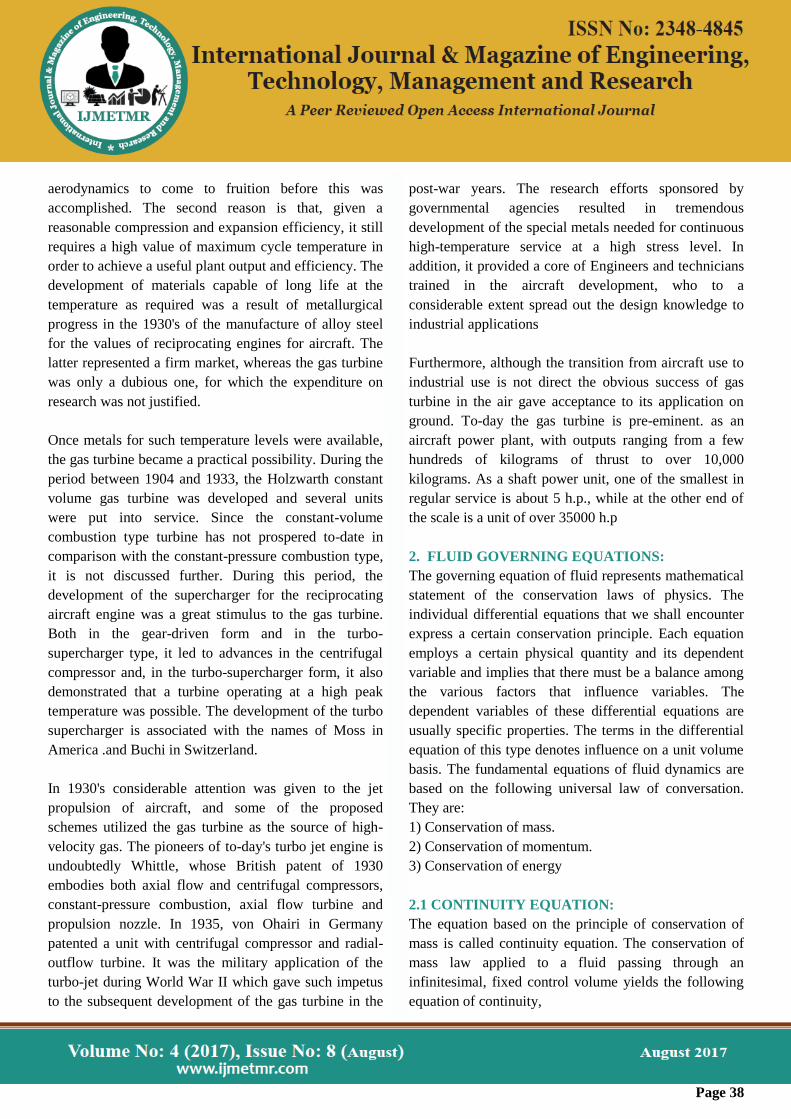
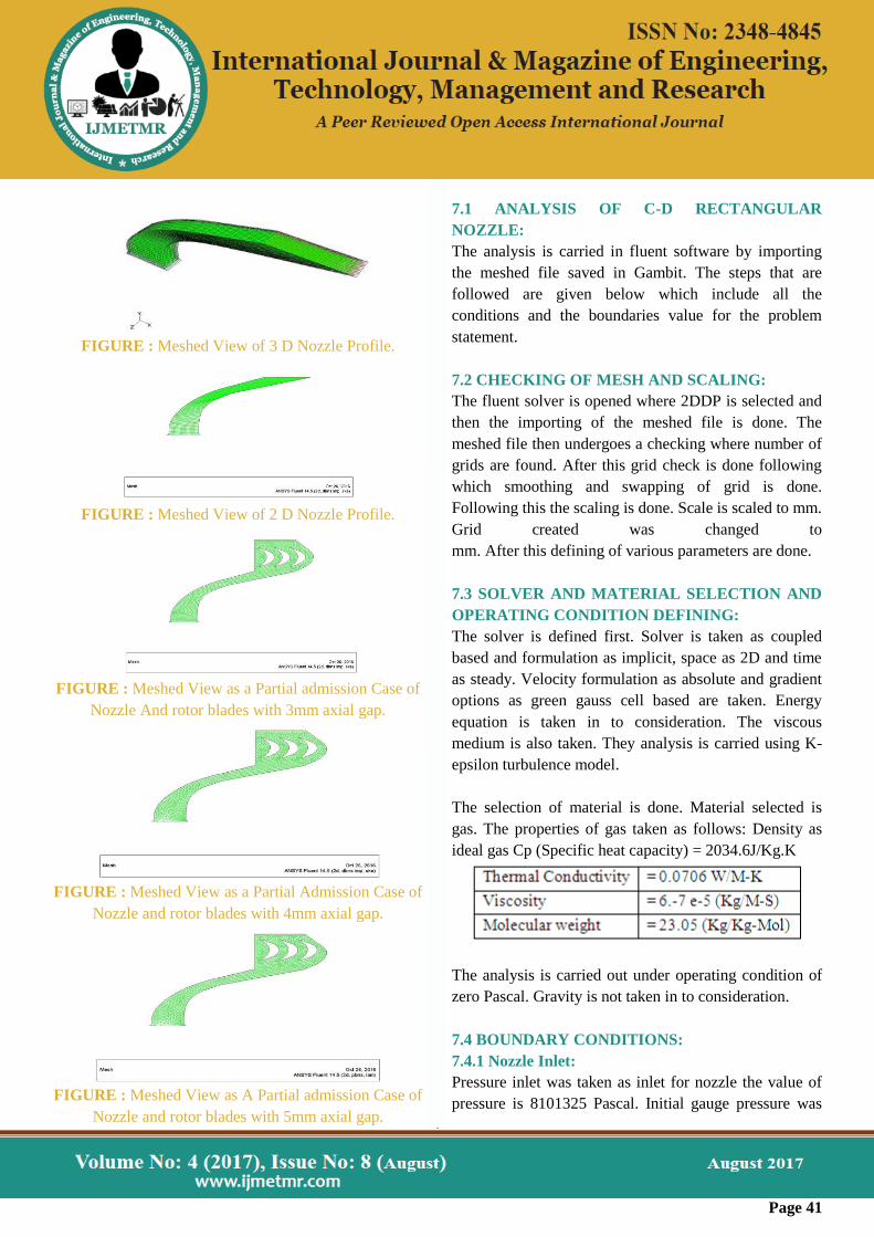
FIGURE : Meshed View of 3 D Nozzle Profile.
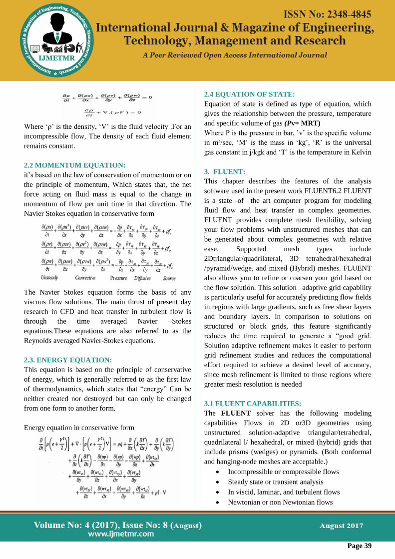
FIGURE : Meshed View of 2 D Nozzle Profile.
FIGURE : Meshed View as a Partial admission Case of
Nozzle And rotor blades with 3mm axial gap.
FIGURE : Meshed View as a Partial Admission Case of
Nozzle and rotor blades with 4mm axial gap.
FIGURE : Meshed View as A Partial admission Case of
Nozzle and rotor blades with 5mm axial gap.
7.1 ANALYSIS OF C-D RECTANGULAR
NOZZLE:
The analysis is carried in fluent software by importing
the meshed file saved in Gambit. The steps that are
followed are given below which include all the
conditions and the boundaries value for the problem
statement.
7.2 CHECKING OF MESH AND SCALING:
The fluent solver is opened where 2DDP is selected and
then the importing of the meshed file is done. The
meshed file then undergoes a checking where number of
grids are found. After this grid check is done following
which smoothing and swapping of grid is done.
Following this the scaling is done. Scale is scaled to mm.
Grid created was changed to
mm. After this defining of various parameters are done.
7.3 SOLVER AND MATERIAL SELECTION AND
OPERATING CONDITION DEFINING:
The solver is defined first. Solver is taken as coupled
based and formulation as implicit, space as 2D and time
as steady. Velocity formulation as absolute and gradient
options as green gauss cell based are taken. Energy
equation is taken in to consideration. The viscous
medium is also taken. They analysis is carried using K-
epsilon turbulence model.
The selection of material is done. Material selected is
gas. The properties of gas taken as follows: Density as
ideal gas Cp (Specific heat capacity) = 2034.6J/Kg.K
The analysis is carried out under operating condition of
zero Pascal. Gravity is not taken in to consideration.
7.4 BOUNDARY CONDITIONS:
7.4.1 Nozzle Inlet:
Pressure inlet was taken as inlet for nozzle the value of
pressure is 8101325 Pascal. Initial gauge pressure was
Page 42
taken as 7898681 Pascal. Temperature was taken as
1583K.
7.4.2 Nozzle Outlet:
The nozzle outlet is set as pressure outlet with a value of
13e5.
7.4.3 Controls set up:
The solution controls are set as listed below: The under
relaxation factor was set as given.
Turbulence Kinetic Energy 0.8
7.4.4 Discretization Equation is selected as given:
Flow (Second order up wind) Turbulence Kinetic
Energy (1st order upwind) Turbulence dissipations rate
(1st order upwind)
7.4.5 Initialization:
Solution initialization is done. Initial values of velocity
are taken as 186.3 m/s for y direction. Temperature is
taken as 1583K Residual monitoring is done and
convergence criteria are set up. The convergence criteria
of various parameters are listed below.
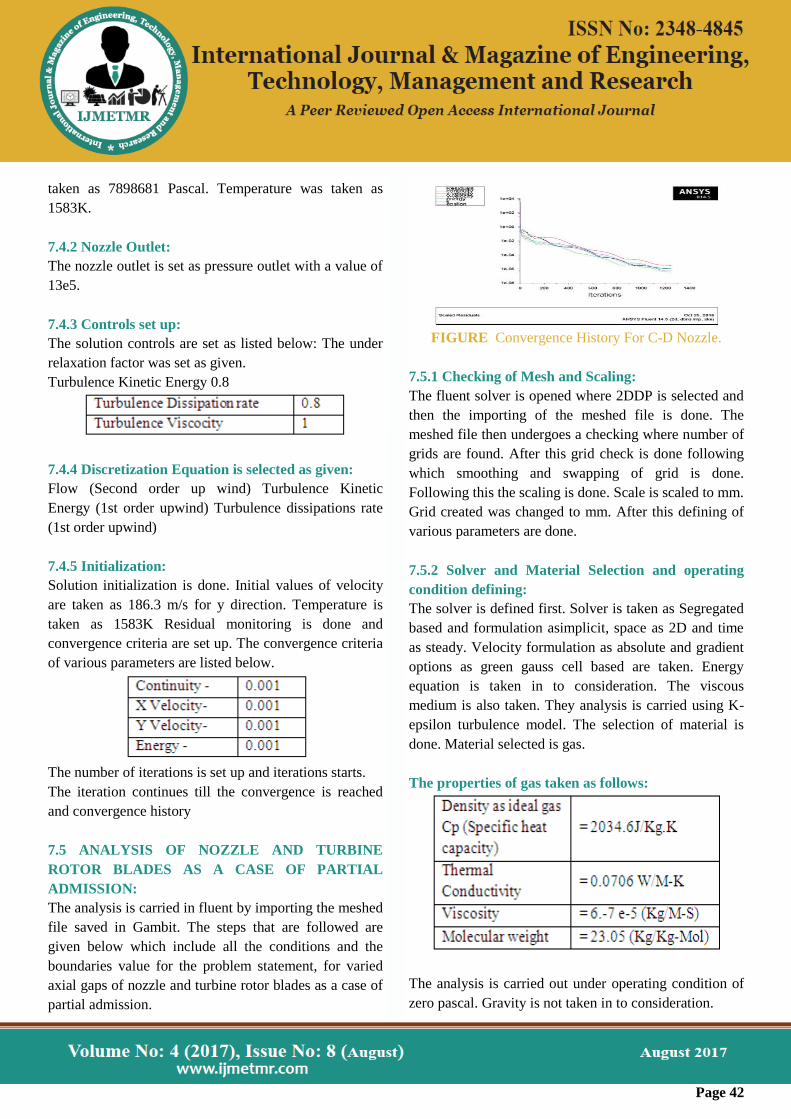
The number of iterations is set up and iterations starts.
The iteration continues till the convergence is reached
and convergence history
7.5 ANALYSIS OF NOZZLE AND TURBINE
ROTOR BLADES AS A CASE OF PARTIAL
ADMISSION:
The analysis is carried in fluent by importing the meshed
file saved in Gambit. The steps that are followed are
given below which include all the conditions and the
boundaries value for the problem statement, for varied
axial gaps of nozzle and turbine rotor blades as a case of
partial admission.
FIGURE Convergence History For C-D Nozzle.
7.5.1 Checking of Mesh and Scaling:
The fluent solver is opened where 2DDP is selected and
then the importing of the meshed file is done. The
meshed file then undergoes a checking where number of
grids are found. After this grid check is done following
which smoothing and swapping of grid is done.
Following this the scaling is done. Scale is scaled to mm.
Grid created was changed to mm. After this defining of
various parameters are done.
7.5.2 Solver and Material Selection and operating
condition defining:
The solver is defined first. Solver is taken as Segregated
based and formulation asimplicit, space as 2D and time
as steady. Velocity formulation as absolute and gradient
options as green gauss cell based are taken. Energy
equation is taken in to consideration. The viscous
medium is also taken. They analysis is carried using K-
epsilon turbulence model. The selection of material is
done. Material selected is gas.
The properties of gas taken as follows:
The analysis is carried out under operating condition of
zero pascal. Gravity is not taken in to consideration.
Page 43
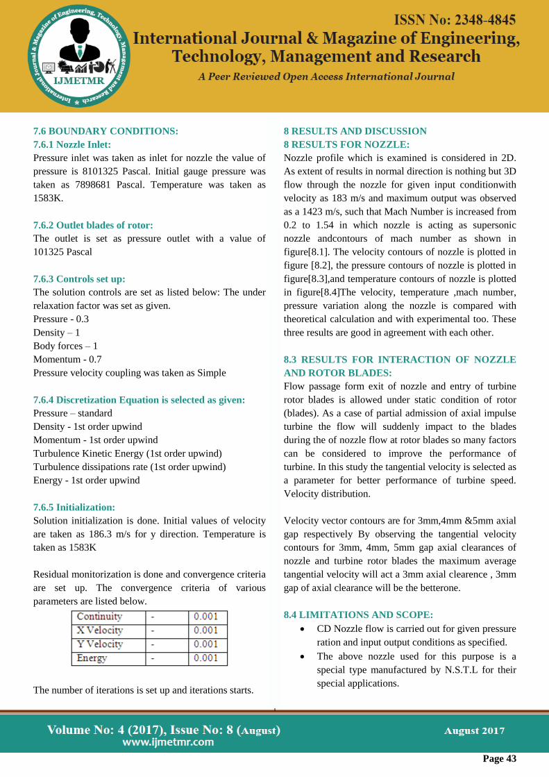
7.6 BOUNDARY CONDITIONS:
7.6.1 Nozzle Inlet:
Pressure inlet was taken as inlet for nozzle the value of
pressure is 8101325 Pascal. Initial gauge pressure was
taken as 7898681 Pascal. Temperature was taken as
1583K.
7.6.2 Outlet blades of rotor:
The outlet is set as pressure outlet with a value of
101325 Pascal
7.6.3 Controls set up:
The solution controls are set as listed below: The under
relaxation factor was set as given.
Pressure - 0.3
Density – 1
Body forces – 1
Momentum - 0.7
Pressure velocity coupling was taken as Simple
7.6.4 Discretization Equation is selected as given:
Pressure – standard
Density - 1st order upwind
Momentum - 1st order upwind
Turbulence Kinetic Energy (1st order upwind)
Turbulence dissipations rate (1st order upwind)
Energy - 1st order upwind
7.6.5 Initialization:
Solution initialization is done. Initial values of velocity
are taken as 186.3 m/s for y direction. Temperature is
taken as 1583K
Residual monitorization is done and convergence criteria
are set up. The convergence criteria of various
parameters are listed below.
The number of iterations is set up and iterations starts.
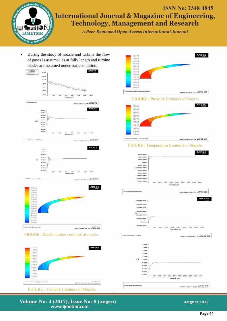
8 RESULTS AND DISCUSSION
8 RESULTS FOR NOZZLE:
Nozzle profile which is examined is considered in 2D.
As extent of results in normal direction is nothing but 3D
flow through the nozzle for given input conditionwith
velocity as 183 m/s and maximum output was observed
as a 1423 m/s, such that Mach Number is increased from
0.2 to 1.54 in which nozzle is acting as supersonic
nozzle andcontours of mach number as shown in
figure[8.1]. The velocity contours of nozzle is plotted in
figure [8.2], the pressure contours of nozzle is plotted in
figure[8.3],and temperature contours of nozzle is plotted
in figure[8.4]The velocity, temperature ,mach number,
pressure variation along the nozzle is compared with
theoretical calculation and with experimental too. These
three results are good in agreement with each other.
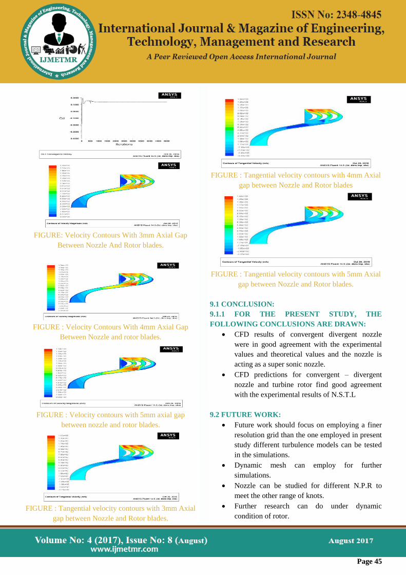
8.3 RESULTS FOR INTERACTION OF NOZZLE
AND ROTOR BLADES:
Flow passage form exit of nozzle and entry of turbine
rotor blades is allowed under static condition of rotor
(blades). As a case of partial admission of axial impulse
turbine the flow will suddenly impact to the blades
during the of nozzle flow at rotor blades so many factors
can be considered to improve the performance of
turbine. In this study the tangential velocity is selected as
a parameter for better performance of turbine speed.
Velocity distribution.
Velocity vector contours are for 3mm,4mm &5mm axial
gap respectively By observing the tangential velocity
contours for 3mm, 4mm, 5mm gap axial clearances of
nozzle and turbine rotor blades the maximum average
tangential velocity will act a 3mm axial clearence , 3mm
gap of axial clearance will be the betterone.
8.4 LIMITATIONS AND SCOPE:
CD Nozzle flow is carried out for given pressure
ration and input output conditions as specified.
The above nozzle used for this purpose is a
special type manufactured by N.S.T.L for their
special applications.
Page 44
During the study of nozzle and turbine the flow
of gases is assumed as at fully length and turbine
blades are assumed under staticcondition.
FIGURE : Mach number contours of nozzle.
FIGURE : Velocity Contours of Nozzle.
FIGURE : Pressure Contours of Nozzle
FIGURE : Temperature Contours of Nozzle.
Page 45
FIGURE: Velocity Contours With 3mm Axial Gap
Between Nozzle And Rotor blades.
FIGURE : Velocity Contours With 4mm Axial Gap
Between Nozzle and rotor blades.
FIGURE : Velocity contours with 5mm axial gap
between nozzle and rotor blades.
FIGURE : Tangential velocity contours with 3mm Axial
gap between Nozzle and Rotor blades.
FIGURE : Tangential velocity contours with 4mm Axial
gap between Nozzle and Rotor blades
FIGURE : Tangential velocity contours with 5mm Axial
gap between Nozzle and Rotor blades.
9.1 CONCLUSION:
9.1.1 FOR THE PRESENT STUDY, THE
FOLLOWING CONCLUSIONS ARE DRAWN:
CFD results of convergent divergent nozzle
were in good agreement with the experimental
values and theoretical values and the nozzle is
acting as a super sonic nozzle.
CFD predictions for convergent – divergent
nozzle and turbine rotor find good agreement
with the experimental results of N.S.T.L
9.2 FUTURE WORK:
Future work should focus on employing a finer
resolution grid than the one employed in present
study different turbulence models can be tested
in the simulations.
Dynamic mesh can employ for further
simulations.
Nozzle can be studied for different N.P.R to
meet the other range of knots.
Further research can do under dynamic
condition of rotor.

Page 46
REFERENCES
1) Bong-Gunshin, Young-Jae Kwak, Kui-soon Kim and
Jin-Han Kim, “A study on nozzle –Rotor Interaction
losses for geometric conditions of a partial admission
impulse turbine”. Proceedings of Asian joint conference
on propulsion and power 2006 Beijing, China, April 20-
23, 2006.
2) A.A.Khan and T.R.Shem bharkar, “Viscous flow
analysis in a convergent – Divergent nozzle”.
Proceedings of the international conference on Aero
space science and Technology, Banglore, India, June 26-
28, 2008.
3) H.K.Versteeg and W.Malala Sekhara, “An
introduction to Computational fluid Dynamics”, British
library cataloguing pub, 4th edition, 1996.
4) David C.Wil Cox, “Turbulence modeling for CFD”
Second Edition 1998.
5) S. Majumdar and B.N.Rajani, “Grid generation for
Abritrary 3-D configuration using a Differential
Algebraic Hybrid Method, CTFD Division, NAL,
Bangalore, April 1995.
6) Layton, W. Sahin and Volker.J, “A problem solving
Approach using Les for a backward facing – step” 2002.
7) M.M.Atha vale and H.Q. Yang, “coupled field
thermal structural simulations in Micro Valves and
Micro channels” CFD research corporation.
8) Lars Davidson, “An introduction to turbulence
Models”, Department of thermo and fluid dynamics,
Chalmers university of technology, Goteborg, Sweden,
November, 2003.
9) Mas Mohas Rai, “Three-Dimensional Navier – Stokes
Simulations of turbine Rotor-Stator interaction, NASA
Ames Research Center, Moffett Field, California Vol.5,
No.3, May – June 1989.
10) Kazuhiro Nakahashi, “Navier – Stokes
Computations of two and three dimensional cascade
flow fields”, Vol.5, No.3, May – June 1989
11) Philip C.E. Jorojenson and Rodrick V.China, “
Explicit Range – Kutta Method for unsteady Rotor
Stator Interaction”, Vol.6, No.6, June 1989.
12) Md.Akhtaruzzaman Sarker and David G.Rhodes,
“3D free surface model of laboratory channel with
Rectangular Broad – crested weir”, proceedings 28th
IAHR Congress, Graz, Austria, 1999.
13) Leonid Moroz, Yuri Gororuschenko, Petr Pagur,
“Axial turbine stanges design: ID/2D/3D simulation,
Experimal, Optimization”, Proceedings of GT 2005
ASME Turbo Expo 2005: Nerada USA.
14) Nicholas J. Georgia dis, Teryn W.Dal Bellow,
chorles J.Tretry, and Albert L.Johns, “Aerodynamic
Design and analysis of High performance nozzles for
Mach 4 Accebrator Vehicles”, 44th AIAA Aero Space
Sciences meeting and exhibit, 9-12 January 2006,
Nerada.
15) Eric Gamble and Dan Haid, “Improving off Design
nozzle performance using fluid injection” AIAA-2004 –
1206 USA.
16) K.Sukati and Y.Shinizu, “Effect of the increase in
the entrance convergent section length of the gun nozzle
on the high velocity oxygen fuel and cold spray
process”, 24th October 2000 ASM international.
17) E.V.Volpe, L.C. decastro sartos “Boundary and
internal conditions for adjoins fluid – flow problems”.
29 June 2007 Springer science Business Media B.V.
2008.
18) B.Jodoin, “Cold Spray nozzle Mach number
limitation‟, February 14 2001, ASM international.

Page 47
Author Details
D Chaitan Kumar
M.Tech (Thermal Engineering) Student
Department of Mechanical Engineering
Aditya Institute of Technology and Management,
Tekkali
Professor Dr. N. Haribabu Was Born Srikakulam,
Andhra Pradesh, India. He Has Received P.Hd
(Thermal) And M.Tech(MEMH) From ANDHRA
UNIVERSITY, VISHAKAPATNAM. HE IS
WORKING AS Professor In Department Of Mechanical
Engineering, Aditya Institute Of Technology &
Management, Tekkali, AP.