Embed Size (px)
Citation preview
Compendium Part C – Equipment
Phases with SFC Types (V8.1)
___________________
___________________
___________________
___________________
___________________
___________________
___________________
___________________
SIMATIC
Process Control System PCS 7 Compendium Part C – Equipment Phases with SFC Types (V8.1)
Operating Manual
Valid for PCS 7 V8.1
01/2015 A5E35031809-AA
Preface 1
What's new? 2
Introduction 3
Basics 4
Components of equipment modules
5
State logic of equipment modules
6
Functionalities and Solution Paths
7
Notes, recommendations, and guidelines
8
Siemens AG Division Digital Factory Postfach 48 48 90026 NÜRNBERG GERMANY
A5E35031809-AA Ⓟ 01/2015 Subject to change
Copyright © Siemens AG 2015. All rights reserved
Legal information Warning notice system
This manual contains notices you have to observe in order to ensure your personal safety, as well as to prevent damage to property. The notices referring to your personal safety are highlighted in the manual by a safety alert symbol, notices referring only to property damage have no safety alert symbol. These notices shown below are graded according to the degree of danger.
DANGER indicates that death or severe personal injury will result if proper precautions are not taken.
WARNING indicates that death or severe personal injury may result if proper precautions are not taken.
CAUTION indicates that minor personal injury can result if proper precautions are not taken.
NOTICE indicates that property damage can result if proper precautions are not taken.
If more than one degree of danger is present, the warning notice representing the highest degree of danger will be used. A notice warning of injury to persons with a safety alert symbol may also include a warning relating to property damage.
Qualified Personnel The product/system described in this documentation may be operated only by personnel qualified for the specific task in accordance with the relevant documentation, in particular its warning notices and safety instructions. Qualified personnel are those who, based on their training and experience, are capable of identifying risks and avoiding potential hazards when working with these products/systems.
Proper use of Siemens products Note the following:
WARNING Siemens products may only be used for the applications described in the catalog and in the relevant technical documentation. If products and components from other manufacturers are used, these must be recommended or approved by Siemens. Proper transport, storage, installation, assembly, commissioning, operation and maintenance are required to ensure that the products operate safely and without any problems. The permissible ambient conditions must be complied with. The information in the relevant documentation must be observed.
Trademarks All names identified by ® are registered trademarks of Siemens AG. The remaining trademarks in this publication may be trademarks whose use by third parties for their own purposes could violate the rights of the owner.
Disclaimer of Liability We have reviewed the contents of this publication to ensure consistency with the hardware and software described. Since variance cannot be precluded entirely, we cannot guarantee full consistency. However, the information in this publication is reviewed regularly and any necessary corrections are included in subsequent editions.
Siemens AG Division Digital Factory Postfach 48 48 90026 NÜRNBERG GERMANY
A5E35031809-AA Ⓟ 01/2015 Subject to change
Copyright © Siemens AG 2015. All rights reserved
Security information Siemens provides products and solutions with industrial security functions that support the secure operation of plants, solutions, machines, equipment and/or networks. They are important components in a holistic industrial security concept. With this in mind, Siemens’ products and solutions undergo continuous development. Siemens recommends strongly that you regularly check for product updates.
For the secure operation of Siemens products and solutions, it is necessary to take suitable preventive action (e.g. cell protection concept) and integrate each component into a holistic, state-of-the-art industrial security concept. Third-party products that may be in use should also be considered. For more information about industrial security, visit
http://www.siemens.com/industrialsecurity
To stay informed about product updates as they occur, sign up for a product-specific newsletter. For more information, visit
http://support.automation.siemens.com/.
Compendium Part C – Equipment Phases with SFC Types (V8.1) Operating Manual, 01/2015, A5E35031809-AA 4
Table of contents
1 Preface ................................................................................................................................................... 7
2 What's new? ......................................................................................................................................... 10
3 Introduction ........................................................................................................................................... 11
4 Basics ................................................................................................................................................... 14
4.1 Equipment module ................................................................................................................. 14 4.1.1 Separation and shared resources .......................................................................................... 14 4.1.2 Reducing the number of different types ................................................................................. 15 4.1.3 Control strategies ................................................................................................................... 15 4.1.4 Modes and states ................................................................................................................... 16 4.1.5 Self-terminating EM and non-self-terminating EM ................................................................. 16 4.1.6 Type and instance model ....................................................................................................... 17
4.2 Example: Division in the P&I diagram .................................................................................... 17
4.3 Example: EM type .................................................................................................................. 18
4.4 Performance specification, requirement specification, test log .............................................. 18
4.5 Template for creating an SFC type ........................................................................................ 19
5 Components of equipment modules ...................................................................................................... 20
5.1 Control strategies (CS) .......................................................................................................... 20
5.2 Setpoints ................................................................................................................................ 21
5.3 Process values ....................................................................................................................... 21
5.4 Control values ........................................................................................................................ 21
5.5 Parameters ............................................................................................................................. 21
5.6 Bit memories .......................................................................................................................... 21
5.7 Times ..................................................................................................................................... 22
5.8 Note texts ............................................................................................................................... 22
5.9 Block contacts ........................................................................................................................ 22
5.10 Position texts .......................................................................................................................... 22
5.11 Messages ............................................................................................................................... 23
5.12 Sequencing logic .................................................................................................................... 23
Preface
Compendium Part C – Equipment Phases with SFC Types (V8.1) Operating Manual, 01/2015, A5E35031809-AA 5
6 State logic of equipment modules .......................................................................................................... 24
6.1 Starting/Run division ............................................................................................................... 26
6.2 Completing and Completed .................................................................................................... 28
6.3 Differences between the "Held" and "Held (Error)" branches ................................................. 28
6.4 Holding, Held, and Resuming ................................................................................................. 29
6.5 Error, Held (error), and Resuming (error) ............................................................................... 29
6.6 Aborting and Stopping ............................................................................................................ 30
7 Functionalities and Solution Paths ......................................................................................................... 31
7.1 State change ........................................................................................................................... 31
7.2 Closing and resumption lockouts ............................................................................................ 32
7.3 Active control strategy change ................................................................................................ 33
7.4 Setpoint changes during operation ......................................................................................... 34
7.5 Transmitting messages ........................................................................................................... 35
7.6 Using times ............................................................................................................................. 38 7.6.1 Example: Using times ............................................................................................................. 38 7.6.2 Example: Calculating the elapsed time................................................................................... 40 7.6.3 Example: Times in Hold .......................................................................................................... 41
7.7 Presetting control strategies ................................................................................................... 42
7.8 Instance-specific deselection and selection of control strategies ........................................... 42
7.9 Multiplexing control modules .................................................................................................. 43
7.10 Control modules in Auto and Manual modes .......................................................................... 44
7.11 Optional control modules ........................................................................................................ 45
7.12 Setting position texts ............................................................................................................... 46
7.13 Self-terminating and non-self-terminating equipment modules .............................................. 47
7.14 Returns when resuming .......................................................................................................... 48
7.15 Calculations ............................................................................................................................ 52
7.16 Start conditions for sequencers .............................................................................................. 53
7.17 "Preprocessing"/"Postprocessing" Tab ................................................................................... 54
Preface
Compendium Part C – Equipment Phases with SFC Types (V8.1) 6 Operating Manual, 01/2015, A5E35031809-AA
8 Notes, recommendations, and guidelines .............................................................................................. 55
8.1 Naming ................................................................................................................................... 55
8.2 Combining sequencers .......................................................................................................... 59
8.3 Editing within the project ........................................................................................................ 60
8.4 Block size of an SFC type ...................................................................................................... 61
8.5 SFC type following CPU STOP/restart .................................................................................. 61
8.6 Non-retentive and retentive sequencers ................................................................................ 62
8.7 Final step ................................................................................................................................ 62
8.8 Connecting to SIMATIC BATCH ............................................................................................ 63
8.9 EPH and EOP ........................................................................................................................ 64
8.10 Multiple instances of a type in a unit ...................................................................................... 65
8.11 Closing lockout, start disable for SIMATIC BATCH ............................................................... 65
8.12 Start and resumption lock for SIMATIC BATCH for equipment module previously started manually ..................................................................................................................... 65
8.13 Continuous function ............................................................................................................... 66
Compendium Part C – Equipment Phases with SFC Types (V8.1) Operating Manual, 01/2015, A5E35031809-AA 7
Preface 1
Subject of the SIMATIC PCS 7 compendium SIMATIC PCS 7, as a distinctly open system, can be flexibly adapted to a wide range of customer needs. The system software provides the project engineer with a great deal of freedom in terms of project configuration, as well as in the design of the program and visualization.
Experience has shown that subsequent modernization or plant expansion work is made much easier if the project is configured "in conformance with SIMATIC PCS 7" as far as possible right from the start. This means users must adhere to certain basic rules to ensure that the provided system functions will offer optimum usability in the future.
This manual serves as a compendium to the product documentation covering SIMATIC PCS 7. The basic tasks for creating and configuring the project are described in the form of instructions with numerous illustrations.
The compendium directly reflects the recommended method for configuration, which is based on the results of a great deal of practical experience. The description relates to working with the project and the parameter settings of the components it contains but not the application itself.
The compendium is divided into the following parts:
● Configuration guidelines including checklist
● Process safety including two checklists
● Technical functions with SFC types
● Operation and maintenance including checklist
● Hardware installation including checklist
● Industrial Security
Validity This documentation is valid for the software packages:
● SIMATIC PCS 7 V8.1
SIMATIC PCS 7 documentation Full SIMATIC PCS 7 documentation is available to you free of charge and in multiple languages in PDF format at www.siemens.com/pcs7-documentation.
Preface
Compendium Part C – Equipment Phases with SFC Types (V8.1) 8 Operating Manual, 01/2015, A5E35031809-AA
Subject of Part C - Technical Functions with SFC Types Part C focuses on implementing equipment phases with the help of SFC types.
The description can be used for individual phases in continuous processes or for supporting SIMATIC BATCH applications in a "SIMATIC PCS 7-compliant" manner.
Particular attention is paid to the following topics:
● Terms
● State logics
● Functionalities
● Solutions, recommendations
● Connecting to SIMATIC BATCH
Additional support If this manual does not contain the answers to any questions you may have about how to use the products described, please contact your local Siemens representative.
You can locate your contact at http://www.siemens.com/automation/partner.
The guide that provides details of the technical documentation offered for the individual SIMATIC products and systems is available at http://www.siemens.de/simatic-tech-doku-portal.
The online catalog and online ordering system are available at www.siemens.com/industrymall.
Training center Siemens offers a number of training courses to familiarize you with the SIMATIC PCS 7 process control system. Contact your regional training center or the main training center in Nuremberg 90327, Germany (http://www.sitrain.com).
Technical support You can contact technical support for all Industry Automation and Drive Technology products using the Support Request web form (http://www.siemens.de/automation/support-request).
More information about our technical support services is available on the Internet at http://support.automation.siemens.com/WW/view/en/16604318.
Preface
Compendium Part C – Equipment Phases with SFC Types (V8.1) Operating Manual, 01/2015, A5E35031809-AA 9
Industry Online Support on the Internet In addition to our documentation options, our expertise is also available to you online (http://support.automation.siemens.com).
Here you will find:
● Overview of the most important technical information and solutions for PCS 7 under http://www.siemens.com/industry/onlinesupport/pcs7.
● The newsletter that keeps you constantly up to date with the latest information about our products
● The right documents for you via the search facility in our Industry Online Support portal
● A forum that provides users and specialists with an international platform for exchanging experience
● Your local contact for Industry Automation & Drive Technology
● Information about local service, repairs, spare parts. The "Services" section offers even more options.
Compendium Part C – Equipment Phases with SFC Types (V8.1) Operating Manual, 01/2015, A5E35031809-AA 10
What's new? 2
The contents of the compendium have been updated in accordance with the new functions and operator input options of SIMATIC PCS 7 V8.1.
Alterations and additions have been described in this compendium particularly in the areas of optimization and improvement of errors.
Compendium Part C – Equipment Phases with SFC Types (V8.1) Operating Manual, 01/2015, A5E35031809-AA 11
Introduction 3
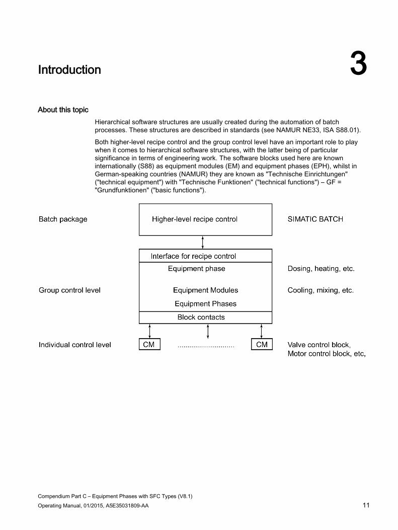
About this topic Hierarchical software structures are usually created during the automation of batch processes. These structures are described in standards (see NAMUR NE33, ISA S88.01).
Both higher-level recipe control and the group control level have an important role to play when it comes to hierarchical software structures, with the latter being of particular significance in terms of engineering work. The software blocks used here are known internationally (S88) as equipment modules (EM) and equipment phases (EPH), whilst in German-speaking countries (NAMUR) they are known as "Technische Einrichtungen" ("technical equipment") with "Technische Funktionen" ("technical functions") – GF = "Grundfunktionen" ("basic functions").
Introduction
Compendium Part C – Equipment Phases with SFC Types (V8.1) 12 Operating Manual, 01/2015, A5E35031809-AA
Content of this document This manual describes how equipment modules/phases can be implemented in SIMATIC PCS 7 with the help of SFC types. It represents a supplement to the "SIMATIC Process Control System PCS 7 SFC for SIMATIC S7" (http://support.automation.siemens.com/WW/view/en/90663402) manual and provides additional information as regards the configuration of EMs and their properties.
Various procedures are described at certain points throughout the documentation, although they are not exhaustive. Sometimes a preferred procedure will be described; in other cases, the selection will depend on various supplementary conditions, such as:
● Application
● History
● Customer philosophy
● Minimization of implementation work
● Minimization of system load
● Etc.
Within the framework of a project a consistent method should be selected and kept to throughout the project.

Introduction
Compendium Part C – Equipment Phases with SFC Types (V8.1) Operating Manual, 01/2015, A5E35031809-AA 13
Definition of terms Internationally recognized terms are mainly used in this documentation. How these terms relate to German terms previously used and their sources (standards) is shown in the table below.
Term used in this document German
(source) English (source)
Unit Teilanlage (NE33) Unit (NE33 English version and S88.01)
Equipment module (EM) in the physical model (plant model)
Technische Einrichtung (NE33), Grundfunktionsbaustein (GF)
Equipment module (EM) (NE33 English version and S88.01)
Equipment phase (EPH) in the procedural model (recipe hierarchy)
Techn. Einrichtung, Technische Funktion (NE33) Equipment phase (EPH) (S88.01)
Setpoint (SP) Sollwert (= Führungsparameter) (allg. üblich) setpoint (customary) Process value (PV) Istwert (= Rückmeldeparameter) (allg. üblich) actual value, process value (cus-
tomary) Mode Betriebsart (allg. üblich) (operation) mode (S88.01) State Betriebszustand (allg. üblich) (operation) state (S88.01) Control Module (CM) Einzelsteuereinheit (allg. üblich)
Grundfunktionselement (GFE) control module (CM) (S88.01)
Control module Messstelle Control module (CM) Equipment phase (EPH) Technische Einrichtung, Technische Funktion (NE33) equipment phase (EPH) (S88.01) P&I diagram Piping and instrumentation diagram P&I diagram
Compendium Part C – Equipment Phases with SFC Types (V8.1) Operating Manual, 01/2015, A5E35031809-AA 14
Basics 4
This section describes the general structure of an equipment module using examples.
4.1 Equipment module
Equipment module (EM) An equipment module (EM) is a closed process-engineering unit. It is used to implement a task definition on the group control level and, thus, a process-engineering (sub)task.
The scope of equipment modules and the types derived from them can be freely defined. By making the right selections, you will be able to find types which can be used outside of the specific unit class, or even the specific plant, in question. On the other hand, specific process-engineering features are reflected in the equipment module design so that it is rarely possible to create general libraries which are not application-specific (unlike on a control module).
4.1.1 Separation and shared resources In order to specify the EM in a given plant structure, we recommend that all control modules involved in implementing the same process-engineering function be grouped together in the P&I diagram (example: Heating/cooling system, dosing devices, template, ventilation system, etc.).
The separation between EMs (as components of a unit/S88: unit) and standalone units is not always obvious, as the example of a reservoir shows. You should find the following explanation useful:
"A unit cannot contain more than one batch at a time."
If the process operation is configured such that the next batch will be started in the reservoir while the previous batch is still being processed in the main unit, the reservoir must be modeled as a separate unit.
The aim of separating the EM is to assign precisely one EM to each control module. In some cases it may be necessary for two different EMs to share one control module (CM) ("shared resources"). This is not a problem for read-only access, but if actuators are to be activated, the resolution of possible conflicts must be considered (S88: "arbitration").
Basics 4.1 Equipment module
Compendium Part C – Equipment Phases with SFC Types (V8.1) Operating Manual, 01/2015, A5E35031809-AA 15
Shared resources of this type should be avoided, as they generate additional planning and configuration effort and come with the risk of usage conflicts during production. In practice, however, shared resources cannot be avoided 100 % of the time.
See also Multiplexing control modules (Page 43)
4.1.2 Reducing the number of different types When defining the EM, take reusability into account so that the number of different EM types can be kept as small as possible (reducing engineering work and the AS resources which must be used). This relates to both the sequencing logic and the use of the same instrumentation, as far as possible. If the plant equipment is not specified accordingly, work with "optional CMs". Optional CMs are control modules which may be available in equipment modules.
Note
You can find more information about this in the section titled Optional control modules (Page 45)
4.1.3 Control strategies Various process-engineering sequences can be implemented using the unit instrumentation belonging to one EM. For example, acid dosing can both provide a certain amount of substance as well as set a pH value. These alternative EM operating methods are referred to as "control strategies" (CS). Control strategies have different sequences and different sets of setpoint parameters.
In selecting the control strategy, different sequencers or alternative branches of a RUN sequencer can be activated, along with the associated setpoint sets. The RUN sequencer is activated via the starting conditions of the step sequencer, using the "QCS" output.
Control strategies and their associated step sequencers can be selected/deselected on an instance-specific basis using the available equipment property during implementation.
The EM returns to its initial state to facilitate a change from one control strategy to another. Depending on requirements, it may be necessary to implement an "active control strategy change", whereby a new control strategy is activated directly from a different control strategy, in order to prevent motors being switched off temporarily, for example.
Note
You can find more information about this in the section titled Active control strategy change (Page 33).
Basics 4.1 Equipment module
Compendium Part C – Equipment Phases with SFC Types (V8.1) 16 Operating Manual, 01/2015, A5E35031809-AA
4.1.4 Modes and states An EM has different modes of operation (S88: Modes such as "manual", "automatic") and various operating states (S88: states; e.g. "Starting", "Run", "Holding", etc.). The states are defined in an operating state logic.
The SFC editor can be used to define any states and transitions you like. These must be coordinated with the EM states in conjunction with higher-level recipe control.
4.1.5 Self-terminating EM and non-self-terminating EM
Introduction There are two ways of terminating an EM:
● Self-terminating EM
● Non-self-terminating EM
Both termination methods are supported by the operating state logic. The EM algorithm controls this process by setting the corresponding states.
Self-terminating EM With a self-terminating EM, the EM algorithm automatically detects that the process-engineering target has been reached and sets the state to "Completed". If "Auto" mode is being used, the higher-level control resets the EM to its initial state. If "Manual" mode is being used, the state either needs to be reset manually or the "selfreset" property needs to be activated. A typical example of this is a dosing procedure.
Non-self-terminating EM With a non-self-terminating EM, the EM algorithm runs until an interim target is reached and sets the state to "Ready to complete". The phase remains active in this state. If "Auto" mode is being used, the higher-level control (e.g. SIMATIC BATCH) detects this state and starts to check the subsequent step enabling conditions in the control recipe. If these conditions are met, a second handshake is performed with the EM, whereby the EM is disabled and reset to its initial state. The higher-level control then activates the next recipe step. If "Manual" mode is being used, the EM must be terminated manually.
A typical example of a non-self-terminating EM is a mixing procedure which is to be terminated by an external event (e.g. the end of a dosing procedure running simultaneously):
● The active interim state is achieved when the target mixing speed is reached (READY_TC: "Ready to complete").
● The completed dosing procedure switches the mixer off.
Basics 4.2 Example: Division in the P&I diagram
Compendium Part C – Equipment Phases with SFC Types (V8.1) Operating Manual, 01/2015, A5E35031809-AA 17
4.1.6 Type and instance model The type/instance model comes into effect when SFC types are used. This means:
● The block structure (list of input and output parameters, including default values) and sequencing logic are defined in the SFC type. The sequencing logic is only able to access the block inputs and outputs.
● The input parameters can be re-parameterized or interconnected and instance-specific high and low limits can be defined, etc. at the SFC instance.
● Control strategies can also be selected/deselected at the SFC instance using the available equipment property.
● Subsequent changes to the SFC type can be made at a central location and then automatically passed on to the SFC instances.
The type/instance model brings with it significant benefits when it comes to configuring, qualifying, servicing, and maintaining the plant. However, it requires every value to be read or written to be managed via the block inputs/outputs.
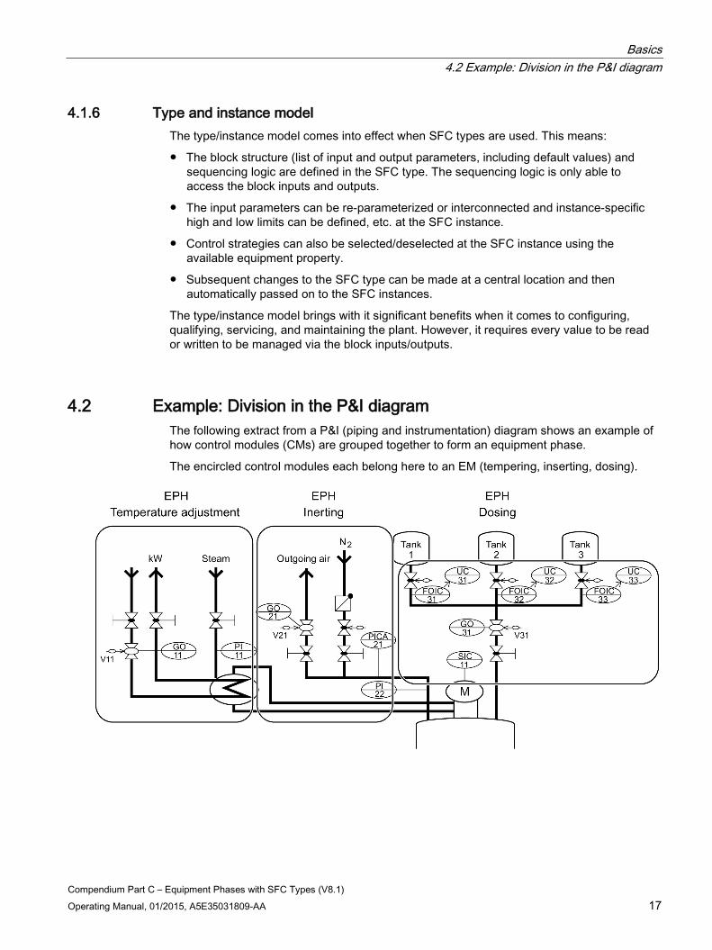
4.2 Example: Division in the P&I diagram The following extract from a P&I (piping and instrumentation) diagram shows an example of how control modules (CMs) are grouped together to form an equipment phase.
The encircled control modules each belong here to an EM (tempering, inserting, dosing).
Basics 4.3 Example: EM type
Compendium Part C – Equipment Phases with SFC Types (V8.1) 18 Operating Manual, 01/2015, A5E35031809-AA
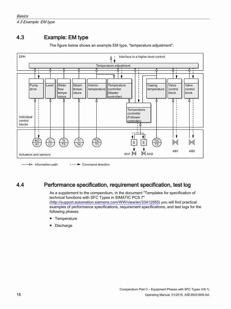
4.3 Example: EM type The figure below shows an example EM type, "temperature adjustment".
4.4 Performance specification, requirement specification, test log As a supplement to the compendium, in the document "Templates for specification of technical functions with SFC Types in SIMATIC PCS 7" (http://support.automation.siemens.com/WW/view/en/33412955) you will find practical examples of performance specifications, requirement specifications, and test logs for the following phases:
● Temperature
● Discharge

Basics 4.5 Template for creating an SFC type
Compendium Part C – Equipment Phases with SFC Types (V8.1) Operating Manual, 01/2015, A5E35031809-AA 19
4.5 Template for creating an SFC type
To help you create an equipment module you will find the following work templates in the document "Templates for specification of technical functions with SFC Types in SIMATIC PCS 7" (http://support.automation.siemens.com/WW/view/en/33412955) as a supplement to the compendium:
● Creating an SFC type
Planning template designed to facilitate implementation of the EM by means of the SFC type.
● Instantiation
Table templates designed to facilitate instantiation of the SFC types).
Compendium Part C – Equipment Phases with SFC Types (V8.1) Operating Manual, 01/2015, A5E35031809-AA 20
Components of equipment modules 5
The information provided in this section is required to implement an equipment module and must be specified at the start of EM configuration. This information is needed in order to write a requirement specification. These components are significant in terms of behavior (e.g. control strategy) on the one hand, and for the interface of the SFC types (e.g. setpoints, CMs) on the other.
The significance of these components is described in the SFC Online Help (keyword: Characteristics of the SFC type) and is looked at again here from the point of view of the "Equipment Module".
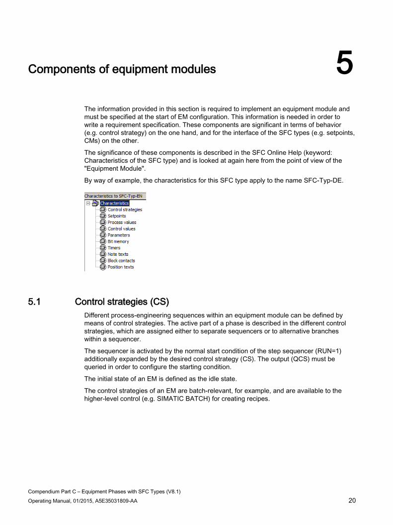
By way of example, the characteristics for this SFC type apply to the name SFC-Typ-DE.
5.1 Control strategies (CS) Different process-engineering sequences within an equipment module can be defined by means of control strategies. The active part of a phase is described in the different control strategies, which are assigned either to separate sequencers or to alternative branches within a sequencer.
The sequencer is activated by the normal start condition of the step sequencer (RUN=1) additionally expanded by the desired control strategy (CS). The output (QCS) must be queried in order to configure the starting condition.
The initial state of an EM is defined as the idle state.
The control strategies of an EM are batch-relevant, for example, and are available to the higher-level control (e.g. SIMATIC BATCH) for creating recipes.
Components of equipment modules 5.2 Setpoints
Compendium Part C – Equipment Phases with SFC Types (V8.1) Operating Manual, 01/2015, A5E35031809-AA 21
5.2 Setpoints Setpoints can be used to influence the behavior of the control strategies and the control of the SFC type. They can be specified by means of operator input or by a higher-level control (SIMATIC BATCH, for example). Setpoints can be assigned to individual control strategies.
When a setpoint is defined, an input is automatically created for the associated actual value. Setpoints of an SFC type contain block contacts for process and control values.
The setpoints of an equipment module are batch-relevant and are referred to as parameters on the higher-level control (e.g. SIMATIC BATCH), although they should not be confused with the parameters of the SFC type.
Special features of setpoints are the "PI" and "PO" data types available, which represent a REAL setpoint and are supplemented by the additional attributes "Material" and "Tracking ID". Data types "PI" and "PO" are required, for example, if setpoint values are used with reference to materials or material tracking via SIMATIC BATCH according to SIMATIC IT.
The "DEST", "SOURCE", "VIA", and "TKEY" data types are also available. You can assign enumerations to these and they are required for SIMATIC Route Control and SIMATIC IT.
5.3 Process values Process values are used to connect process signals (e.g. temperature or level) to the function and to control the SFC type. Process values report actual values to the phase, so the EM does not have to be activated. The individual signals can, therefore, be connected to several equipment modules in order to use them in the sequencing logic.
Process values are primarily used for step enabling conditions in step sequencers.
5.4 Control values Control values are used to control blocks which are not connected to the phase via the CM interface. This can be used, for example, to separate a cascade controller.
5.5 Parameters Parameters are used to modify the behavior of the SFC type on an instance-specific basis (e.g. limit values, options).
5.6 Bit memories Bit memories serve as a clipboard for values. They are created as static variables, which are not visible on the interface display in CFC.
Components of equipment modules 5.7 Times
Compendium Part C – Equipment Phases with SFC Types (V8.1) 22 Operating Manual, 01/2015, A5E35031809-AA
5.7 Times Timers are often needed when implementing equipment modules, such as a monitoring time or run time for a mixer. Timers can be implemented using a standard timer block (TIMER_P), which supports different modes.
Possible modes for the timer block: pulse, extended pulse, ON delay, latching ON delay, OFF delay. When the SFC type is used, the timer block is automatically embedded for processing times.
5.8 Note texts Note texts are used for displaying additional notes on the operator station (OS). They can also be used to display additional information in tandem with a message in the event of an error. Configuration work needs to be carried out in order to utilize this function.
The texts, which are predefined in the characteristics dialog, can be displayed simply by setting an output (OPTIPNO) on the interface. These note texts can be acknowledged by the operator. A note text is not connected to the signaling system; it is used for operator prompting (visible as extra information).
5.9 Block contacts Block contacts are blocks on the control module. The control module (CM) is activated by the equipment module. As well as block activation, feedback on the relevant state is also required. These activations and feedbacks are connected to the EM via interface elements.
A cohesive group of interface elements is called a block contact.
In order to be able to use block contacts to connect basic control blocks, you must specify at block type level the relevant I/Os for creating a link to an SFC type.
This is achieved by assigning the "S7_contact = true" system attribute to the block I/O. The technological blocks from the PCS 7 Advanced Process Library are prepared accordingly. If required, you can make project-specific modifications to the block types supplied in terms of the relevant I/Os.
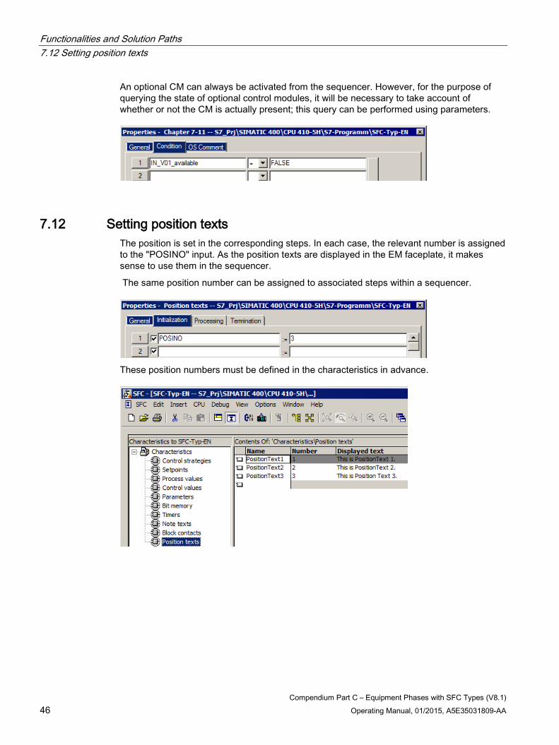
5.10 Position texts Position texts are used for the additional display of the current sequence state on the operator station (OS). Position texts can be set in the sequential control system and displayed on the EM faceplate. Furthermore, the position text can be used in a higher-level control to query an interim state, for example. An example is the querying of rough/fine dosing.
Components of equipment modules 5.11 Messages
Compendium Part C – Equipment Phases with SFC Types (V8.1) Operating Manual, 01/2015, A5E35031809-AA 23
5.11 Messages Equipment modules transmit messages, which can be set or reset from within the sequence. To do this, the message class and message class must be defined. An example of a message could be a valve fault message or an operator prompt.
5.12 Sequencing logic The process engineering task itself is implemented in the sequencing logic. The behavior in each individual EM state must be defined for the initial state and for every control strategy.
Compendium Part C – Equipment Phases with SFC Types (V8.1) Operating Manual, 01/2015, A5E35031809-AA 24
State logic of equipment modules 6
Core statement You can find the state logic used for the SFC type in the PCS 7 online help or in the "SIMATIC Process Control System PCS 7 SFC for SIMATIC S7" (http://support.automation.siemens.com/WW/view/en/90663402) manual under "Diagram of the state transitions for SFC OSL".
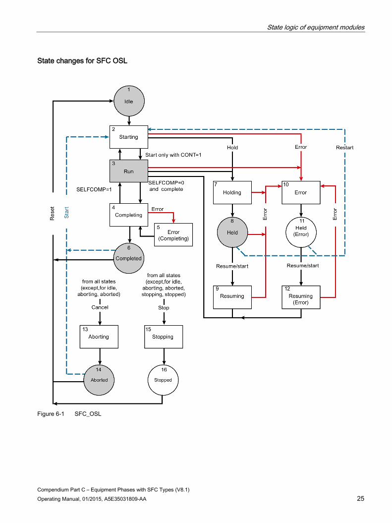
The state logic of the SFC type has 16 different states:
● Ready [1] – Initial state; wait for Start command
● Starting [2] – Start processing after Start command
● Run [3] – Normal processing after ending the Start processing
● Completing [4] – Completion of processing after Complete command or implicit completion
● Error (Completing) [5] – Error processing during Completion processing
● Completed [6] – Completion of processing is finished; waiting for Reset or Start command
● Holding [7] – Hold processing after Hold command
● Held [8] – Hold processing completed; waiting for Resume command
● Resuming [9] – Resume processing after Resume command
● Error [10] – Error processing if errors occur
● Held (error) [11] – Error processing is complete and no more errors are present; waiting for Resume command
● Resuming (error) [12] – Resuming processing after Resume command
● Aborting [13] – Aborting processing after Abort command
● Aborted [14] – Abort processing is complete; waiting for Reset or Start command
● Stopping [15] – Stopping processing after Stop command
● Stopped [16] – Stop processing completed; waiting for Reset command
A sequencer can be stored in the transient states (e.g. "Starting" [2], "Completing" [4], "Aborting" [13], etc.):
Sequencers cannot be integrated in the final states (e.g. "Completed" [6], "Aborted" [14], etc.).
State logic of equipment modules
Compendium Part C – Equipment Phases with SFC Types (V8.1) Operating Manual, 01/2015, A5E35031809-AA 25
State changes for SFC OSL
Figure 6-1 SFC_OSL
State logic of equipment modules 6.1 Starting/Run division
Compendium Part C – Equipment Phases with SFC Types (V8.1) 26 Operating Manual, 01/2015, A5E35031809-AA
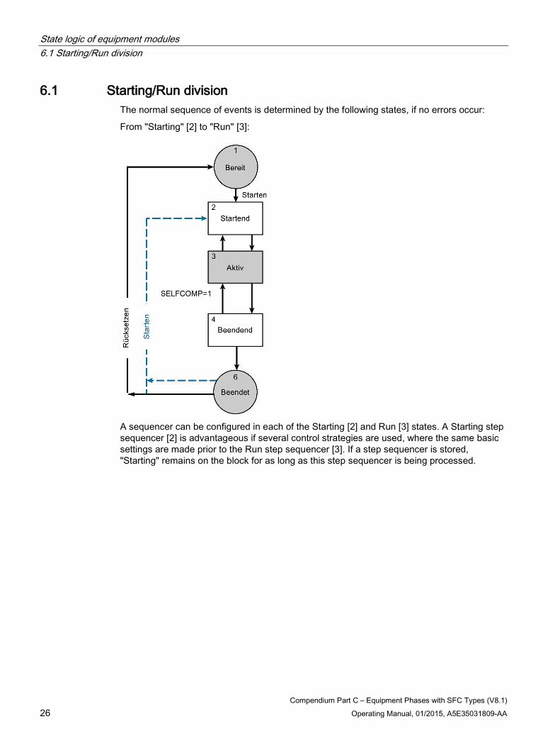
6.1 Starting/Run division The normal sequence of events is determined by the following states, if no errors occur:
From "Starting" [2] to "Run" [3]:
A sequencer can be configured in each of the Starting [2] and Run [3] states. A Starting step sequencer [2] is advantageous if several control strategies are used, where the same basic settings are made prior to the Run step sequencer [3]. If a step sequencer is stored, "Starting" remains on the block for as long as this step sequencer is being processed.
State logic of equipment modules 6.1 Starting/Run division
Compendium Part C – Equipment Phases with SFC Types (V8.1) Operating Manual, 01/2015, A5E35031809-AA 27
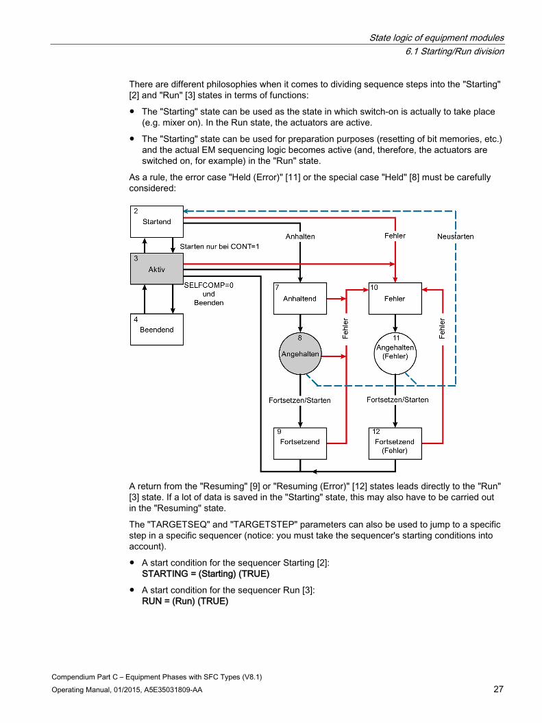
There are different philosophies when it comes to dividing sequence steps into the "Starting" [2] and "Run" [3] states in terms of functions:
● The "Starting" state can be used as the state in which switch-on is actually to take place (e.g. mixer on). In the Run state, the actuators are active.
● The "Starting" state can be used for preparation purposes (resetting of bit memories, etc.) and the actual EM sequencing logic becomes active (and, therefore, the actuators are switched on, for example) in the "Run" state.
As a rule, the error case "Held (Error)" [11] or the special case "Held" [8] must be carefully considered:
A return from the "Resuming" [9] or "Resuming (Error)" [12] states leads directly to the "Run" [3] state. If a lot of data is saved in the "Starting" state, this may also have to be carried out in the "Resuming" state.
The "TARGETSEQ" and "TARGETSTEP" parameters can also be used to jump to a specific step in a specific sequencer (notice: you must take the sequencer's starting conditions into account).
● A start condition for the sequencer Starting [2]: STARTING = (Starting) (TRUE)
● A start condition for the sequencer Run [3]: RUN = (Run) (TRUE)

State logic of equipment modules 6.2 Completing and Completed
Compendium Part C – Equipment Phases with SFC Types (V8.1) 28 Operating Manual, 01/2015, A5E35031809-AA
6.2 Completing and Completed In the "Completing" state [4], the EM is disabled and switched to the safe state in accordance with the stored sequence.
A start condition for the sequencer Completing [4]:
● COMPLETING = Completing (TRUE)
In many cases, these are the same sequences as for the "Aborting" [13] or "Stopping" [15] states. In this case, the "Completing" [4] sequencer can also be used for "Aborting" [13] and "Stopping" [15]. In this case, a start condition for the sequencer "Completing" [4] is:
● COMPLETING = Completi (TRUE) or
● ABORTING = Aborting (TRUE) or
● STOPPING = Stopping (TRUE)
In the "Completed" state [6], the EM is disabled and waiting to be reset. The reset function can be set using a parameter (SELFRESET) in such a way that it will be performed automatically (without operator input) in "Manual" mode. In "Automatic" mode, this is carried out by the higher-level recipe control.
6.3 Differences between the "Held" and "Held (Error)" branches The "Held" [8] branch is intended for scheduled/desired holding procedures. This can also be achieved by operator input in SIMATIC BATCH for example.
The "Held (Error)" [11] branch is intended for an "undesired" error case and is not to be activated manually (except for test purposes).
It is frequently the case that the same thing is implemented in both branches.
State logic of equipment modules 6.4 Holding, Held, and Resuming
Compendium Part C – Equipment Phases with SFC Types (V8.1) Operating Manual, 01/2015, A5E35031809-AA 29
6.4 Holding, Held, and Resuming In the "Holding" state [7] the normal sequence is held and switched to the safe state in accordance with the stored sequence. This can also consist of a targeted shutdown in several stages.
● A start condition for the sequencer Holding [7]: HOLDING = Holding (TRUE)
In the "Resuming" state [9] the EM currently in the "Held" state [8] is restarted. There are various positions at which the active sequencer may restart.
See also Returns when resuming (Page 48)
6.5 Error, Held (error), and Resuming (error) In the "Error" state [10] the lower-level blocks are switched to a safe state. This can also consist of a targeted shutdown in several stages.
● A start condition for the sequencer Error [10]: ERROR = Error (TRUE)
In the "Resume" state [12], the EM currently in the "Held" (error) state [11] is restarted. There are various positions at which the active sequencer may restart.
See also Returns when resuming (Page 48)
State logic of equipment modules 6.6 Aborting and Stopping
Compendium Part C – Equipment Phases with SFC Types (V8.1) 30 Operating Manual, 01/2015, A5E35031809-AA
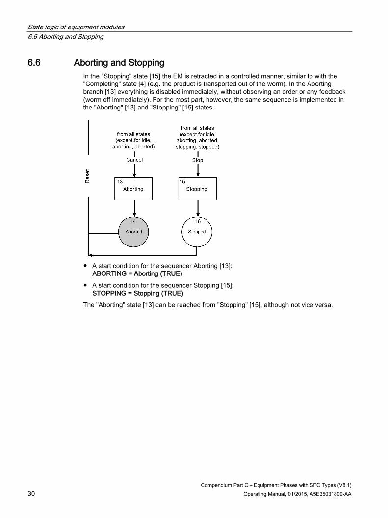
6.6 Aborting and Stopping In the "Stopping" state [15] the EM is retracted in a controlled manner, similar to with the "Completing" state [4] (e.g. the product is transported out of the worm). In the Aborting branch [13] everything is disabled immediately, without observing an order or any feedback (worm off immediately). For the most part, however, the same sequence is implemented in the "Aborting" [13] and "Stopping" [15] states.
● A start condition for the sequencer Aborting [13]:
ABORTING = Aborting (TRUE)
● A start condition for the sequencer Stopping [15]: STOPPING = Stopping (TRUE)
The "Aborting" state [13] can be reached from "Stopping" [15], although not vice versa.
Compendium Part C – Equipment Phases with SFC Types (V8.1) Operating Manual, 01/2015, A5E35031809-AA 31
Functionalities and Solution Paths 7
This section describes the individual task definitions/behaviors of an EM, along with possible solutions.
The solutions refer to creation using the SFC type.
7.1 State change An SFC-type state change (step sequencer change) can be achieved in one of the following ways:
● In "Manual" mode, by means of a manual operation (e.g. via the EM faceplate)
● In "Automatic" mode, by means of the automatic interface
● Via LOCK inputs for interconnections (e.g. LOCKERROR)
● Via INT inputs (e.g. INTHOLD) for a state change from the sequencer
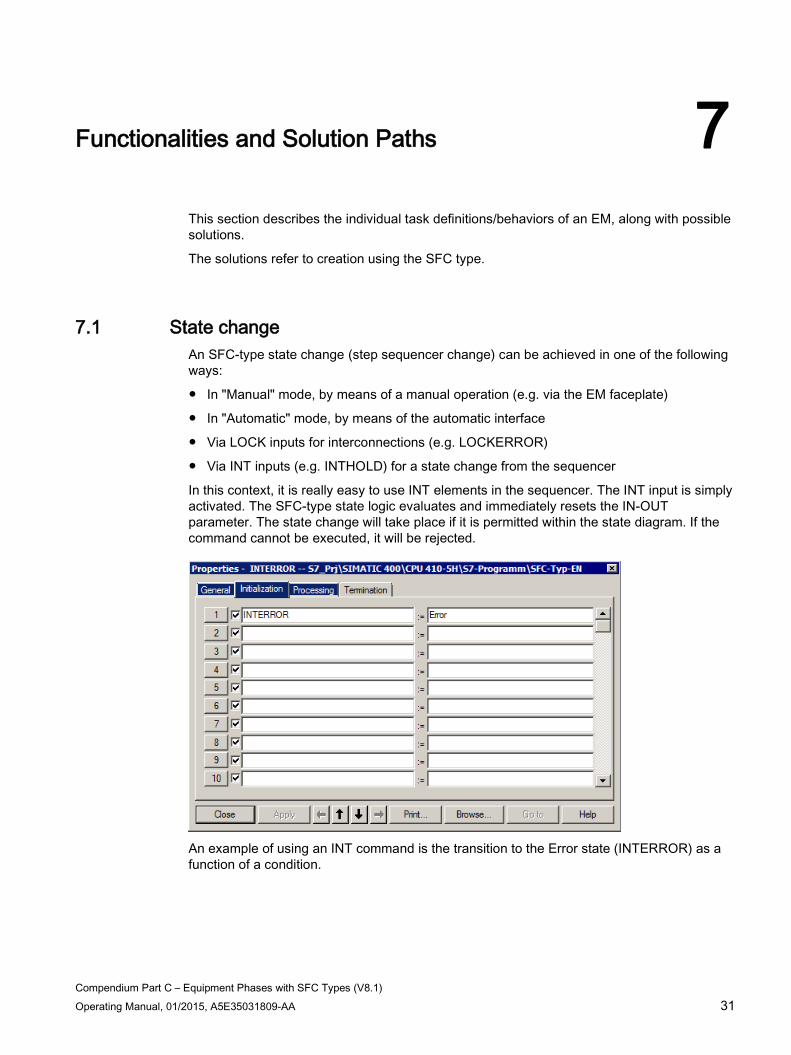
In this context, it is really easy to use INT elements in the sequencer. The INT input is simply activated. The SFC-type state logic evaluates and immediately resets the IN-OUT parameter. The state change will take place if it is permitted within the state diagram. If the command cannot be executed, it will be rejected.
An example of using an INT command is the transition to the Error state (INTERROR) as a function of a condition.
Functionalities and Solution Paths 7.2 Closing and resumption lockouts
Compendium Part C – Equipment Phases with SFC Types (V8.1) 32 Operating Manual, 01/2015, A5E35031809-AA
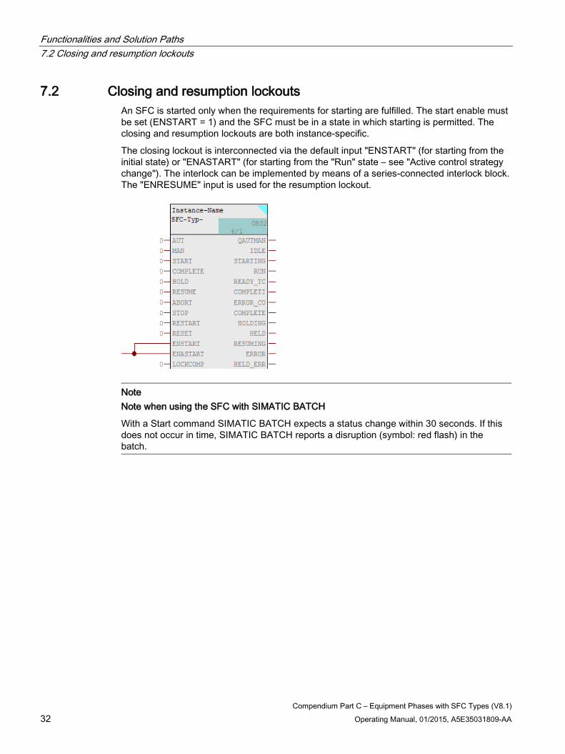
7.2 Closing and resumption lockouts An SFC is started only when the requirements for starting are fulfilled. The start enable must be set (ENSTART = 1) and the SFC must be in a state in which starting is permitted. The closing and resumption lockouts are both instance-specific.
The closing lockout is interconnected via the default input "ENSTART" (for starting from the initial state) or "ENASTART" (for starting from the "Run" state – see "Active control strategy change"). The interlock can be implemented by means of a series-connected interlock block. The "ENRESUME" input is used for the resumption lockout.
Note Note when using the SFC with SIMATIC BATCH
With a Start command SIMATIC BATCH expects a status change within 30 seconds. If this does not occur in time, SIMATIC BATCH reports a disruption (symbol: red flash) in the batch.
Functionalities and Solution Paths 7.3 Active control strategy change
Compendium Part C – Equipment Phases with SFC Types (V8.1) Operating Manual, 01/2015, A5E35031809-AA 33
7.3 Active control strategy change "Active control strategy change" means that a control strategy can be started while another one is running.
An active control strategy change is activated/deactivated on the SFC type via the "ENASTART" (enable active start) input. If the "ENASTART" input is activated, an active control strategy can be aborted when another is started. The same control strategy can also be restarted.
In many cases, the starting conditions for the active control strategy change are the same as those for starting from the initial state. Other conditions can be added to the starting conditions. A condition could be, for example, that the other control strategy may only be switched to once a particular step has been performed in the sequencer. A restriction may also be assigned to the control strategies to be started. This restriction must be implemented by means of external logic.
Note
A prepared control strategy is only adopted during SFC start (both in MANUAL and in AUTO).
If the SFC instance has already started, it must be aborted, stopped, held or processed to the end in order to be able to start again. You can achieve this in MANUAL by means of operator input and in AUTO by interconnecting the appropriate inputs (ABORT, STOP, HOLD, START, RESTART). Also be aware of the OSL (Operating State Logic).

Functionalities and Solution Paths 7.4 Setpoint changes during operation
Compendium Part C – Equipment Phases with SFC Types (V8.1) 34 Operating Manual, 01/2015, A5E35031809-AA
7.4 Setpoint changes during operation If a setpoint needs to be changed during operation, please observe the following:
● Consideration must be given to the setpoint change within the EM sequential control system. It may be the case that a return must be performed within the sequence when a setpoint is changed, or that the setpoint must be assigned in each relevant step (e.g. when forwarding to a CM).
● The setpoint in the EM can only be changed if that EM is in "Manual" mode. In "Automatic" mode, setpoint operation is blocked for equipment modules. In this case, the setpoint operation must be performed by the higher-level recipe control (SIMATIC BATCH).
● If a setpoint change needs to be made in the active state, it must be enabled on the EM block for every setpoint. The enable is implemented via input "xx_ENOP" (xx: I/O name of the setpoint). If input "xx_ENOP" is activated, the setpoint can be changed. The input can also be set or reset in the sequencing logic.
● The setpoint change also has to be activated in the faceplate. The screenshot below shows the setting for faceplate in the image @pg_@sfc_type_actualsp.PDL:
If no setpoint change is required during operation, you can deactivate it for all SFC types in the dialog box too.
Functionalities and Solution Paths 7.5 Transmitting messages
Compendium Part C – Equipment Phases with SFC Types (V8.1) Operating Manual, 01/2015, A5E35031809-AA 35
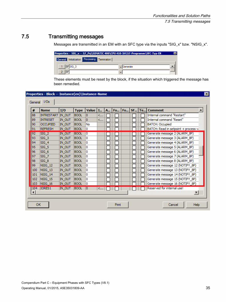
7.5 Transmitting messages Messages are transmitted in an EM with an SFC type via the inputs "SIG_x" bzw. "NSIG_x".
These elements must be reset by the block, if the situation which triggered the message has been remedied.
Functionalities and Solution Paths 7.5 Transmitting messages
Compendium Part C – Equipment Phases with SFC Types (V8.1) 36 Operating Manual, 01/2015, A5E35031809-AA
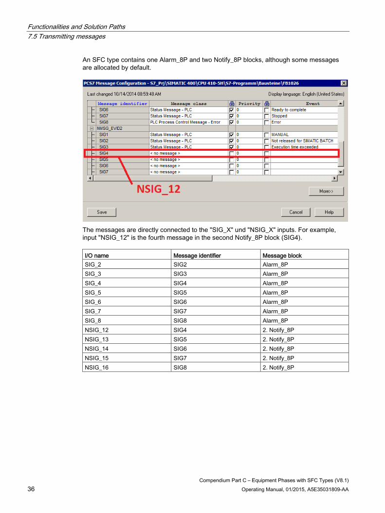
An SFC type contains one Alarm_8P and two Notify_8P blocks, although some messages are allocated by default.
The messages are directly connected to the "SIG_X" und "NSIG_X" inputs. For example, input "NSIG_12" is the fourth message in the second Notify_8P block (SIG4). I/O name Message identifier Message block SIG_2 SIG2 Alarm_8P SIG_3 SIG3 Alarm_8P SIG_4 SIG4 Alarm_8P SIG_5 SIG5 Alarm_8P SIG_6 SIG6 Alarm_8P SIG_7 SIG7 Alarm_8P SIG_8 SIG8 Alarm_8P NSIG_12 SIG4 2. Notify_8P NSIG_13 SIG5 2. Notify_8P NSIG_14 SIG6 2. Notify_8P NSIG_15 SIG7 2. Notify_8P NSIG_16 SIG8 2. Notify_8P
Functionalities and Solution Paths 7.5 Transmitting messages
Compendium Part C – Equipment Phases with SFC Types (V8.1) Operating Manual, 01/2015, A5E35031809-AA 37
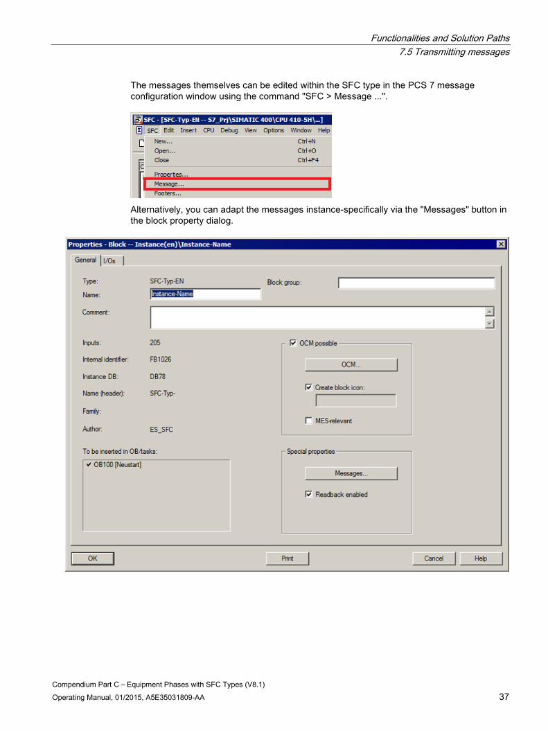
The messages themselves can be edited within the SFC type in the PCS 7 message configuration window using the command "SFC > Message ...".
Alternatively, you can adapt the messages instance-specifically via the "Messages" button in the block property dialog.
Functionalities and Solution Paths 7.6 Using times
Compendium Part C – Equipment Phases with SFC Types (V8.1) 38 Operating Manual, 01/2015, A5E35031809-AA
7.6 Using times
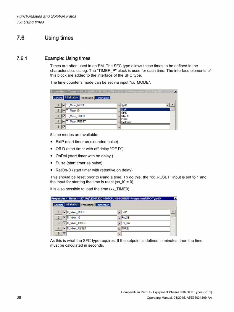
7.6.1 Example: Using times Times are often used in an EM. The SFC type allows these times to be defined in the characteristics dialog. The "TIMER_P" block is used for each time. The interface elements of this block are added to the interface of the SFC type.
The time counter’s mode can be set via input "xx_MODE".
5 time modes are available:
● ExtP (start timer as extended pulse)
● Off-D (start timer with off delay "Off-D")
● OnDel (start timer with on delay )
● Pulse (start timer as pulse)
● RetOn-D (start timer with retentive on delay)
This should be reset prior to using a time. To do this, the "xx_RESET" input is set to 1 and the input for starting the time is reset (xx_I0 = 0).
It is also possible to load the time (xx_TIME0).
As this is what the SFC type requires. If the setpoint is defined in minutes, then the time must be calculated in seconds.

Functionalities and Solution Paths 7.6 Using times
Compendium Part C – Equipment Phases with SFC Types (V8.1) Operating Manual, 01/2015, A5E35031809-AA 39
The block "MUL04" can be used for calculating the time. The time setpoint (e.g. SP_Mix_Q) is interconnected with input "IN1" of block "MUL04". A process value (e.g. PV_Mix) containing the time in seconds is also defined on the EM and interconnected with output OUT of the "MUL04" block.
Once the time "xx_Q0" has been reset, the sequencer can continue.
The reset command on the "Termination" tab is also reset during the reset process (xx_RESET = 0).
If the time is to be started now, the input pulse of the time counter (xx_I0) can be set.
You query whether the time has expired via the output pulse (xx_Q0 = 1).
Functionalities and Solution Paths 7.6 Using times
Compendium Part C – Equipment Phases with SFC Types (V8.1) 40 Operating Manual, 01/2015, A5E35031809-AA
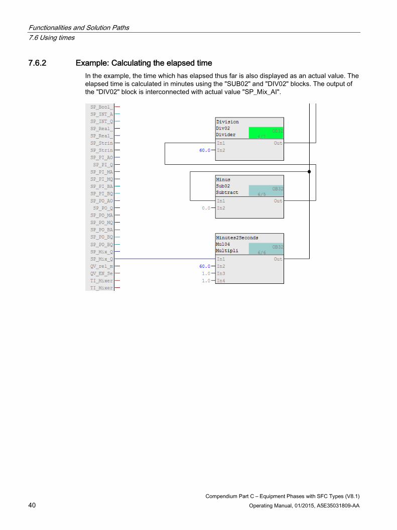
7.6.2 Example: Calculating the elapsed time In the example, the time which has elapsed thus far is also displayed as an actual value. The elapsed time is calculated in minutes using the "SUB02" and "DIV02" blocks. The output of the "DIV02" block is interconnected with actual value "SP_Mix_AI".

Functionalities and Solution Paths 7.6 Using times
Compendium Part C – Equipment Phases with SFC Types (V8.1) Operating Manual, 01/2015, A5E35031809-AA 41
7.6.3 Example: Times in Hold If a time is used (as described up to now), it continues to run if the EM switches to the "Holding" state. If you do not want this to happen, the time must be stored temporarily.
A bit memory is defined for temporary storage in the characteristics dialog (e.g. saved time (I/O name: FL_time)).
The time currently remaining is assigned to the bit memory (xx_PTIME). The input pulse of the time counter (xx_I0) also has to be reset.
The remaining time can be set again in the "Resuming" state.
Functionalities and Solution Paths 7.7 Presetting control strategies
Compendium Part C – Equipment Phases with SFC Types (V8.1) 42 Operating Manual, 01/2015, A5E35031809-AA
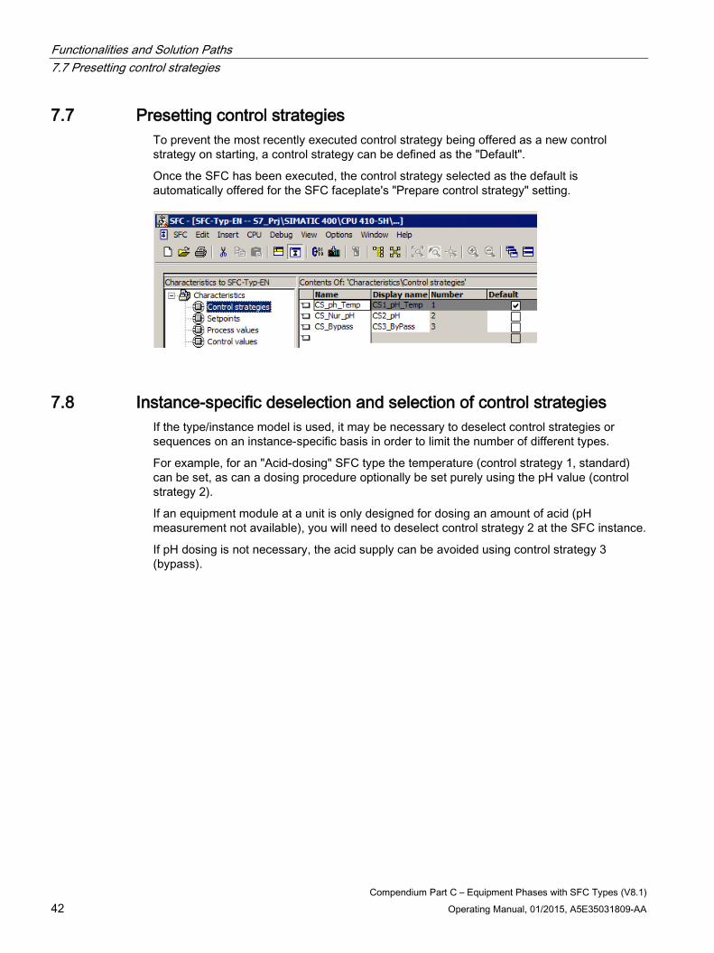
7.7 Presetting control strategies To prevent the most recently executed control strategy being offered as a new control strategy on starting, a control strategy can be defined as the "Default".
Once the SFC has been executed, the control strategy selected as the default is automatically offered for the SFC faceplate's "Prepare control strategy" setting.
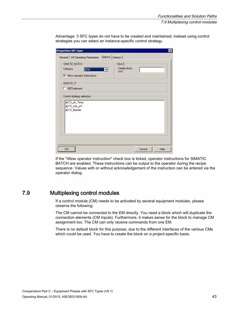
7.8 Instance-specific deselection and selection of control strategies If the type/instance model is used, it may be necessary to deselect control strategies or sequences on an instance-specific basis in order to limit the number of different types.
For example, for an "Acid-dosing" SFC type the temperature (control strategy 1, standard) can be set, as can a dosing procedure optionally be set purely using the pH value (control strategy 2).
If an equipment module at a unit is only designed for dosing an amount of acid (pH measurement not available), you will need to deselect control strategy 2 at the SFC instance.
If pH dosing is not necessary, the acid supply can be avoided using control strategy 3 (bypass).
Functionalities and Solution Paths 7.9 Multiplexing control modules
Compendium Part C – Equipment Phases with SFC Types (V8.1) Operating Manual, 01/2015, A5E35031809-AA 43
Advantage: 3 SFC types do not have to be created and maintained; instead using control strategies you can select an instance-specific control strategy.
If the "Allow operator instruction" check box is ticked, operator instructions for SIMATIC BATCH are enabled. These instructions can be output to the operator during the recipe sequence. Values with or without acknowledgement of the instruction can be entered via the operator dialog.
7.9 Multiplexing control modules If a control module (CM) needs to be activated by several equipment modules, please observe the following:
The CM cannot be connected to the EM directly. You need a block which will duplicate the connection elements (CM inputs). Furthermore, it makes sense for the block to manage CM assignment too. The CM can only receive commands from one EM.
There is no default block for this purpose, due to the different interfaces of the various CMs which could be used. You have to create the block on a project-specific basis.
Functionalities and Solution Paths 7.10 Control modules in Auto and Manual modes
Compendium Part C – Equipment Phases with SFC Types (V8.1) 44 Operating Manual, 01/2015, A5E35031809-AA
7.10 Control modules in Auto and Manual modes
Introduction CMs can be operated both in "Manual" (operating personnel) or "Automatic" (operation via the EM) modes. The four most important options in terms of which mode CMs should be operated in are described below.
All CMs always in Automatic All CMs are switched to "Auto" mode when in their initial state. If a CM is switched to "Manual" mode, the EM develops an error (ERROR). The equipment module can only be started when all CMs are in "Auto" mode (QAUTMAN=AUTO).
All CMs in Manual in Initial and Hold states The CMs can only be switched to "Manual" mode when in their initial state and when in "Hold". The EM can only be started when all CMs are in "Auto" mode (ENSTART). The CMs must be switched to "Automatic" mode prior to starting.
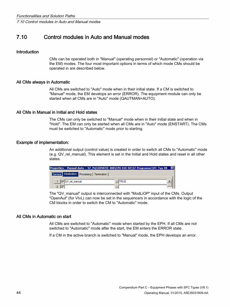
Example of implementation: An additional output (control value) is created in order to switch all CMs to "Automatic" mode (e.g. QV_rel_manual). This element is set in the Initial and Hold states and reset in all other states.
The "QV_manual" output is interconnected with "ModLiOP" input of the CMs. Output "OpenAut" (for VIvL) can now be set in the sequencers in accordance with the logic of the CM blocks in order to switch the CM to "Automatic" mode.
All CMs in Automatic on start All CMs are switched to "Automatic" mode when started by the EPH. If all CMs are not switched to "Automatic" mode after the start, the EM enters the ERROR state.
If a CM in the active branch is switched to "Manual" mode, the EPH develops an error.
Functionalities and Solution Paths 7.11 Optional control modules
Compendium Part C – Equipment Phases with SFC Types (V8.1) Operating Manual, 01/2015, A5E35031809-AA 45
All CMs to AUTO on activation only The CMs are only switched to "Automatic" mode when the equipment module performs an activation in the sequencer. The EM can also be started without all CMs being in "Auto" mode. CMs can be switched to "Manual" mode at any time without the EM developing an error.
Other options and combinations are also possible. The correct one for each particular case will depend on the business and plant operators in question, as well as on how the equipment modules are being used. For example, may a CM be operated manually at all, and what is the plant’s level of automation?
The way in which an EM responds to CM operation will have an effect on recipe control. If the equipment module switches to "Hold", SIMATIC BATCH will respond as well.
Note Rules for automatic operation
In order for the Batch Control Server's commands to be processed in automatic mode, the following inputs must remain unconnected in the interface block and their values set to "1": ENSTART, ENCOMPLETE, ENHOLD, ENRESUME,ENABORT, ENSTOP, ENRESET.
7.11 Optional control modules When defining an EM, it makes sense to keep the number of EM types to a minimum. This can be achieved by using optional CMs for the EM types.
An optional CM is a process tag or single control unit, which is not available in every SFC instance. This could mean, for example, that various control strategies cannot be executed in these SFC instances. These control strategies must be blocked in the SFC instance. However, it may be the case that a control strategy can work with or without optional control modules.
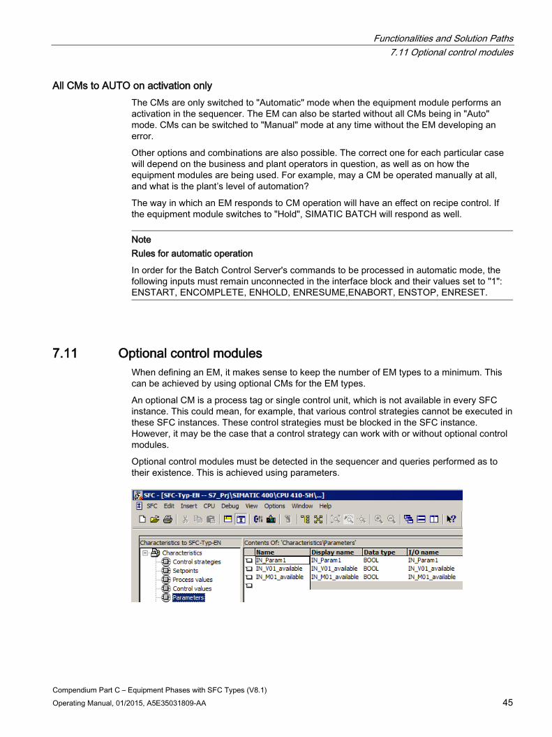
Optional control modules must be detected in the sequencer and queries performed as to their existence. This is achieved using parameters.
Functionalities and Solution Paths 7.12 Setting position texts
Compendium Part C – Equipment Phases with SFC Types (V8.1) 46 Operating Manual, 01/2015, A5E35031809-AA
An optional CM can always be activated from the sequencer. However, for the purpose of querying the state of optional control modules, it will be necessary to take account of whether or not the CM is actually present; this query can be performed using parameters.
7.12 Setting position texts The position is set in the corresponding steps. In each case, the relevant number is assigned to the "POSINO" input. As the position texts are displayed in the EM faceplate, it makes sense to use them in the sequencer.
The same position number can be assigned to associated steps within a sequencer.
These position numbers must be defined in the characteristics in advance.
Functionalities and Solution Paths 7.13 Self-terminating and non-self-terminating equipment modules
Compendium Part C – Equipment Phases with SFC Types (V8.1) Operating Manual, 01/2015, A5E35031809-AA 47
7.13 Self-terminating and non-self-terminating equipment modules
Introduction There are two ways of terminating an EM:
● Self-terminating equipment module
● Non-self-terminating equipment module
The SFC type supports both methods. The configuration is set via the SELFCOMP input. The SELFCOMP input changes the termination behavior of the active sequencer in the SFC type.
Self-terminating EM An example of a self-terminating EM is the dosing procedure. When dosing is complete, the equipment module will be closed automatically.
Non-self-terminating EM An example of a non-self-terminating EM is the mixing procedure.
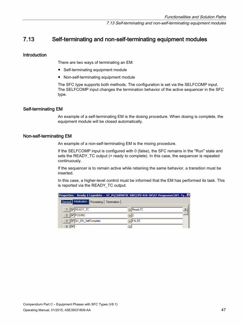
If the SELFCOMP input is configured with 0 (false), the SFC remains in the "Run" state and sets the READY_TC output (= ready to complete). In this case, the sequencer is repeated continuously.
If the sequencer is to remain active while retaining the same behavior, a transition must be inserted.
In this case, a higher-level control must be informed that the EM has performed its task. This is reported via the READY_TC output.
Functionalities and Solution Paths 7.14 Returns when resuming
Compendium Part C – Equipment Phases with SFC Types (V8.1) 48 Operating Manual, 01/2015, A5E35031809-AA
7.14 Returns when resuming
Introduction A return from the "Resuming" state to the "Run" state can be achieved in different ways.
Note
When a state change is performed from "Run" [3] to "Holding" [7] (see the figure below), the active sequencer is held or aborted (depending on RUNHOLD = Response of the RUN-Seq to the "Hold" command: 0: Hold/1: Abort) and the new sequencer is started.
If the previous sequencer has been completely processed, the state changes from "Resuming" [9] to "Run" [3]. The new sequencer is resumed or started (depending on RUNHOLD) at the transition from "Resuming" [9].
In the event of an error, the sequence is as shown in the following figure via "Error" [10] towards "Held (error)" [11] and "Resuming (error)" [12].
If there is an implicit state change, the transition is executed when the sequencer of the first transitional state has been processed completely and is, therefore, terminated. If there is no sequencer with a fulfilled starting condition, the implicit transition is executed immediately and the new sequencer starts.
Functionalities and Solution Paths 7.14 Returns when resuming
Compendium Part C – Equipment Phases with SFC Types (V8.1) Operating Manual, 01/2015, A5E35031809-AA 49
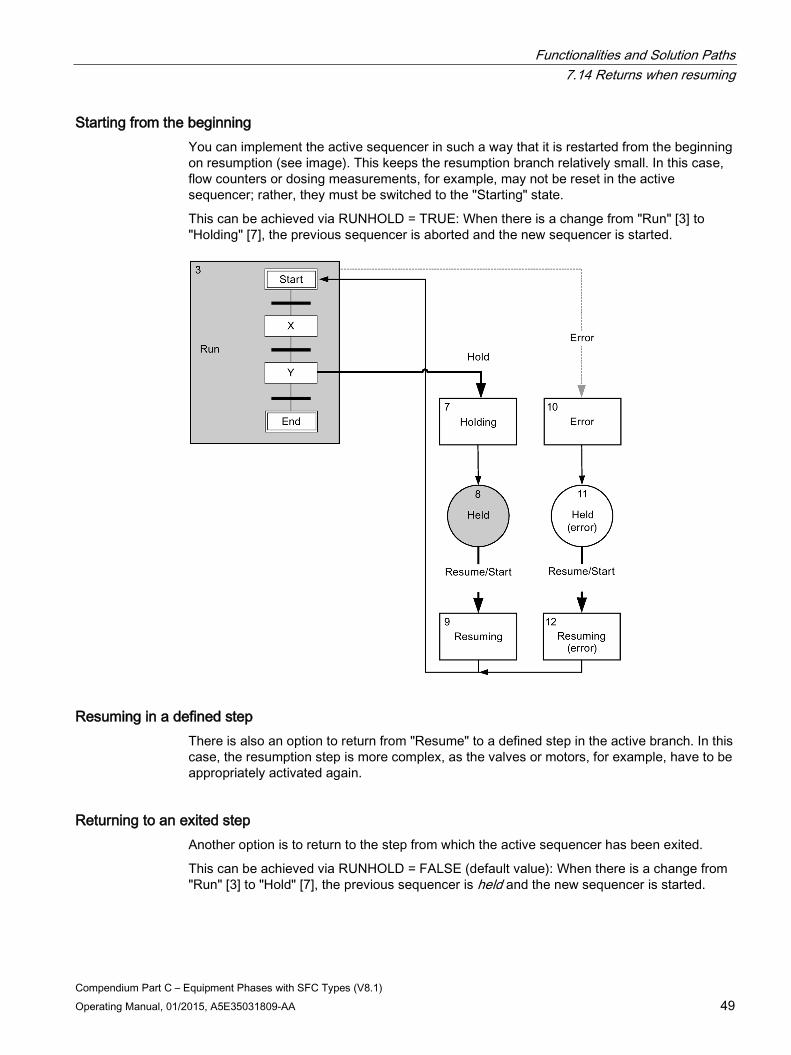
Starting from the beginning You can implement the active sequencer in such a way that it is restarted from the beginning on resumption (see image). This keeps the resumption branch relatively small. In this case, flow counters or dosing measurements, for example, may not be reset in the active sequencer; rather, they must be switched to the "Starting" state.
This can be achieved via RUNHOLD = TRUE: When there is a change from "Run" [3] to "Holding" [7], the previous sequencer is aborted and the new sequencer is started.
Resuming in a defined step There is also an option to return from "Resume" to a defined step in the active branch. In this case, the resumption step is more complex, as the valves or motors, for example, have to be appropriately activated again.
Returning to an exited step Another option is to return to the step from which the active sequencer has been exited.
This can be achieved via RUNHOLD = FALSE (default value): When there is a change from "Run" [3] to "Hold" [7], the previous sequencer is held and the new sequencer is started.
Functionalities and Solution Paths 7.14 Returns when resuming
Compendium Part C – Equipment Phases with SFC Types (V8.1) 50 Operating Manual, 01/2015, A5E35031809-AA
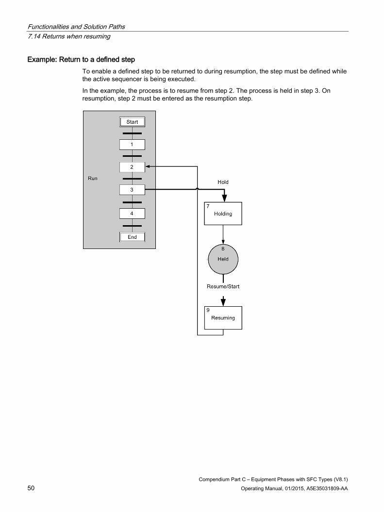
Example: Return to a defined step To enable a defined step to be returned to during resumption, the step must be defined while the active sequencer is being executed.
In the example, the process is to resume from step 2. The process is held in step 3. On resumption, step 2 must be entered as the resumption step.
Functionalities and Solution Paths 7.14 Returns when resuming
Compendium Part C – Equipment Phases with SFC Types (V8.1) Operating Manual, 01/2015, A5E35031809-AA 51
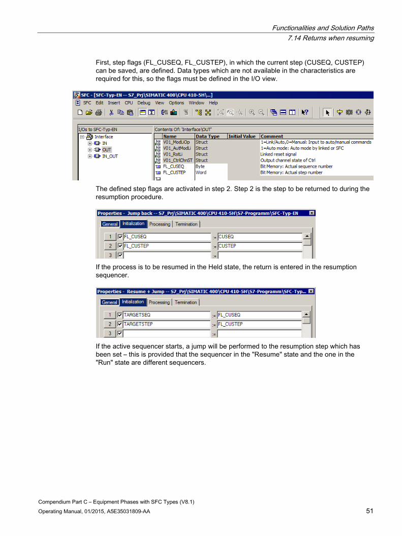
First, step flags (FL_CUSEQ, FL_CUSTEP), in which the current step (CUSEQ, CUSTEP) can be saved, are defined. Data types which are not available in the characteristics are required for this, so the flags must be defined in the I/O view.
The defined step flags are activated in step 2. Step 2 is the step to be returned to during the resumption procedure.
If the process is to be resumed in the Held state, the return is entered in the resumption sequencer.
If the active sequencer starts, a jump will be performed to the resumption step which has been set – this is provided that the sequencer in the "Resume" state and the one in the "Run" state are different sequencers.
Functionalities and Solution Paths 7.15 Calculations
Compendium Part C – Equipment Phases with SFC Types (V8.1) 52 Operating Manual, 01/2015, A5E35031809-AA
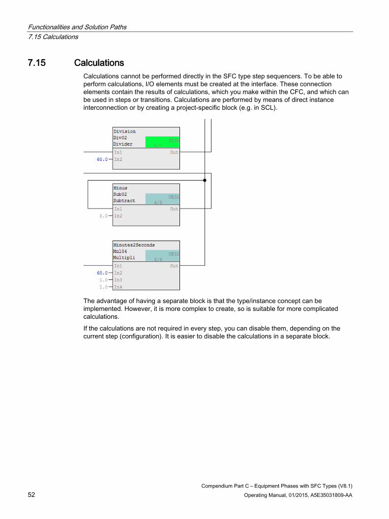
7.15 Calculations Calculations cannot be performed directly in the SFC type step sequencers. To be able to perform calculations, I/O elements must be created at the interface. These connection elements contain the results of calculations, which you make within the CFC, and which can be used in steps or transitions. Calculations are performed by means of direct instance interconnection or by creating a project-specific block (e.g. in SCL).
The advantage of having a separate block is that the type/instance concept can be implemented. However, it is more complex to create, so is suitable for more complicated calculations.
If the calculations are not required in every step, you can disable them, depending on the current step (configuration). It is easier to disable the calculations in a separate block.
Functionalities and Solution Paths 7.16 Start conditions for sequencers
Compendium Part C – Equipment Phases with SFC Types (V8.1) Operating Manual, 01/2015, A5E35031809-AA 53
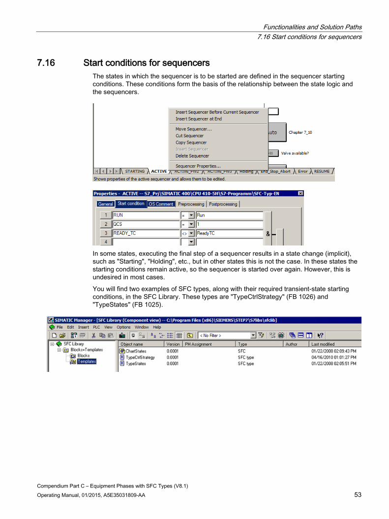
7.16 Start conditions for sequencers The states in which the sequencer is to be started are defined in the sequencer starting conditions. These conditions form the basis of the relationship between the state logic and the sequencers.
In some states, executing the final step of a sequencer results in a state change (implicit), such as "Starting", "Holding", etc., but in other states this is not the case. In these states the starting conditions remain active, so the sequencer is started over again. However, this is undesired in most cases.
You will find two examples of SFC types, along with their required transient-state starting conditions, in the SFC Library. These types are "TypeCtrlStrategy" (FB 1026) and "TypeStates" (FB 1025).
Functionalities and Solution Paths 7.17 "Preprocessing"/"Postprocessing" Tab
Compendium Part C – Equipment Phases with SFC Types (V8.1) 54 Operating Manual, 01/2015, A5E35031809-AA
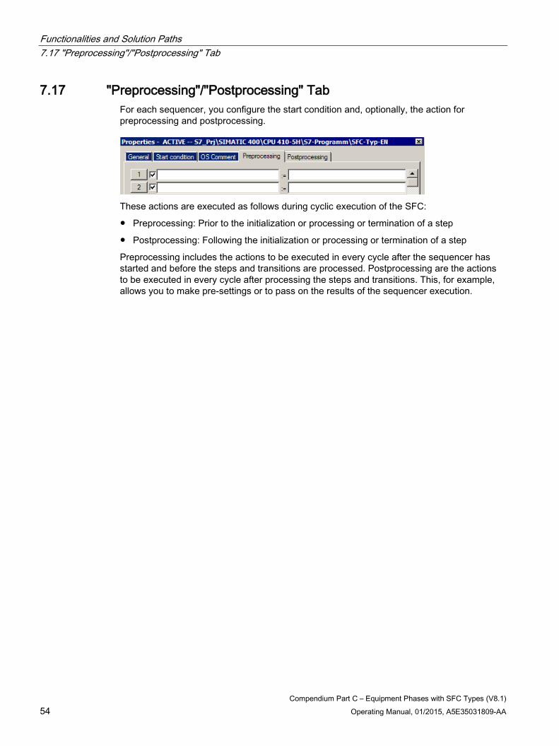
7.17 "Preprocessing"/"Postprocessing" Tab For each sequencer, you configure the start condition and, optionally, the action for preprocessing and postprocessing.
These actions are executed as follows during cyclic execution of the SFC:
● Preprocessing: Prior to the initialization or processing or termination of a step
● Postprocessing: Following the initialization or processing or termination of a step
Preprocessing includes the actions to be executed in every cycle after the sequencer has started and before the steps and transitions are processed. Postprocessing are the actions to be executed in every cycle after processing the steps and transitions. This, for example, allows you to make pre-settings or to pass on the results of the sequencer execution.
Compendium Part C – Equipment Phases with SFC Types (V8.1) Operating Manual, 01/2015, A5E35031809-AA 55
Notes, recommendations, and guidelines 8 8.1 Naming
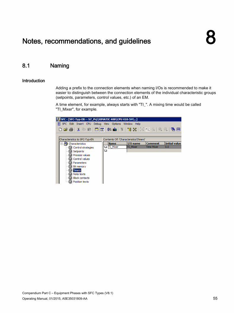
Introduction Adding a prefix to the connection elements when naming I/Os is recommended to make it easier to distinguish between the connection elements of the individual characteristic groups (setpoints, parameters, control values, etc.) of an EM.
A time element, for example, always starts with "TI_". A mixing time would be called "TI_Mixer", for example.
Notes, recommendations, and guidelines 8.1 Naming
Compendium Part C – Equipment Phases with SFC Types (V8.1) 56 Operating Manual, 01/2015, A5E35031809-AA
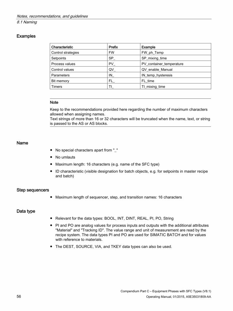
Examples Characteristic Prefix Example Control strategies FW FW_ph_Temp Setpoints SP_ SP_mixing_time Process values PV_ PV_container_temperature Control values QV_ QV_enable_Manual Parameters IN_ IN_temp_hysteresis Bit memory FL_ FL_time Timers TI_ TI_mixing_time
Note
Keep to the recommendations provided here regarding the number of maximum characters allowed when assigning names. Text strings of more than 16 or 32 characters will be truncated when the name, text, or string is passed to the AS or AS blocks.
Name ● No special characters apart from "_"
● No umlauts
● Maximum length: 16 characters (e.g. name of the SFC type)
● ID characteristic (visible designation for batch objects, e.g. for setpoints in master recipe and batch)
Step sequencers ● Maximum length of sequencer, step, and transition names: 16 characters
Data type ● Relevant for the data types: BOOL, INT, DINT, REAL, PI, PO, String
● PI and PO are analog values for process inputs and outputs with the additional attributes "Material" and "Tracking ID". The value range and unit of measurement are read by the recipe system. The data types PI and PO are used for SIMATIC BATCH and for values with reference to materials.
● The DEST, SOURCE, VIA, and TKEY data types can also be used.
Notes, recommendations, and guidelines 8.1 Naming
Compendium Part C – Equipment Phases with SFC Types (V8.1) Operating Manual, 01/2015, A5E35031809-AA 57
Length of I/O name ● Setpoints and times: <= 16 characters
● Block contact: <= 10 characters
● All other characteristics: <= 24 characters
Note
When the interface is generated, suffixes are added to the names of the automatically created I/Os for setpoints, times, and block contacts. When selecting names, remember that only the first eight characters of all contacts can be viewed in CFC.
Long I/O names are only visible in full as tooltip texts.
To ensure that names remain distinguishable, unique, and uniform, it is best to define a naming convention at the start of configuration work.
Comment ● Maximum length: 80 characters
● Only visible in the characteristics dialog
● Value range (low and high limit: <I/O name>_LL and <I/O name>_HL)
● Relevant for the data types: INT, DINT, REAL, PI, PO
● Can be edited in the instance block for data types
Initial value ● Default setpoint value
● Can be set on an instance-specific basis within the value range already defined
Text length ● Relevant for the data type: String
● Can be defined within the value range [1,254]
● Recommendation: Max. text length 32 (for an explanation see notes on this section)
Precision ● Relevant for the data types: REAL, PI and PO
● Determines the number of decimal places to be displayed
● Can be set to between 0 and 7
Notes, recommendations, and guidelines 8.1 Naming
Compendium Part C – Equipment Phases with SFC Types (V8.1) 58 Operating Manual, 01/2015, A5E35031809-AA
Unit ● Relevant for the data types: INT, DINT, REAL, PI, PO
● Defined in shared declarations (max. 16 characters)
● Can be edited on an instance-specific basis in the "S7_unit" system attribute
Text0 and Text1 ● Relevant for the data type: BOOL
● Can be edited at the instance as the "S7_string1" or "S7_string0" system attribute
● Defined in shared declarations (max. 16 characters)
● Is not displayed in SIMATIC BATCH
Enumeration ● Relevant for the data types: BOOL, INT and DINT
● Can be edited at the instance as the "S7_enum" system attribute
● Defined in shared declarations (max. 16 characters)
Possible settings for archiving ● No archiving (S7_archive := 'false')
● Archiving (S7_archive := 'shortterm')
● Long-term archiving (S7_archive := 'longterm')
● Can be edited on an instance-specific basis for I/Os with S7_m_c = 'true'
Notes, recommendations, and guidelines 8.2 Combining sequencers
Compendium Part C – Equipment Phases with SFC Types (V8.1) Operating Manual, 01/2015, A5E35031809-AA 59
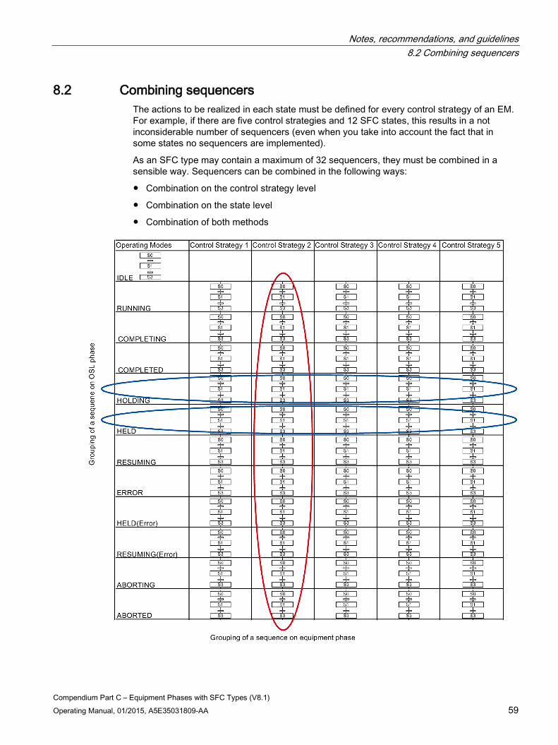
8.2 Combining sequencers The actions to be realized in each state must be defined for every control strategy of an EM. For example, if there are five control strategies and 12 SFC states, this results in a not inconsiderable number of sequencers (even when you take into account the fact that in some states no sequencers are implemented).
As an SFC type may contain a maximum of 32 sequencers, they must be combined in a sensible way. Sequencers can be combined in the following ways:
● Combination on the control strategy level
● Combination on the state level
● Combination of both methods
Notes, recommendations, and guidelines 8.3 Editing within the project
Compendium Part C – Equipment Phases with SFC Types (V8.1) 60 Operating Manual, 01/2015, A5E35031809-AA
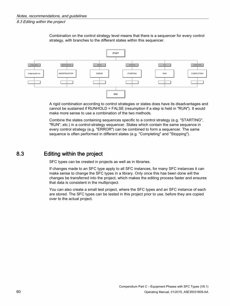
Combination on the control strategy level means that there is a sequencer for every control strategy, with branches to the different states within this sequencer.
A rigid combination according to control strategies or states does have its disadvantages and cannot be sustained if RUNHOLD = FALSE (resumption if a step is held in "RUN"). It would make more sense to use a combination of the two methods.
Combine the states containing sequences specific to a control strategy (e.g. "STARTING", "RUN", etc.) in a control-strategy sequencer. States which contain the same sequence in every control strategy (e.g. "ERROR") can be combined to form a sequencer. The same sequence is often performed in different states (e.g. "Completing" and "Stopping").
8.3 Editing within the project SFC types can be created in projects as well as in libraries.
If changes made to an SFC type apply to all SFC instances, for many SFC instances it can make sense to change the SFC types in a library. Only once this has been done will the changes be transferred into the project, which makes the editing process faster and ensures that data is consistent in the multiproject.
You can also create a small test project, where the SFC types and an SFC instance of each are stored. The SFC types can be tested in this project prior to use, before they are copied over to the actual project.
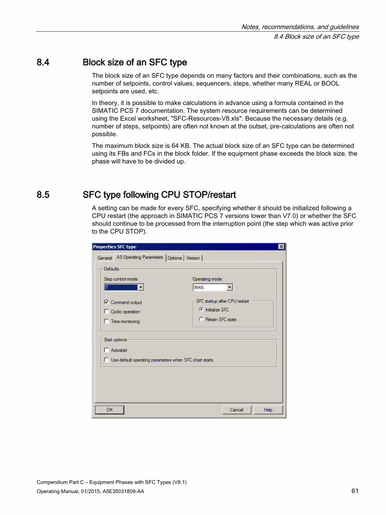
Notes, recommendations, and guidelines 8.4 Block size of an SFC type
Compendium Part C – Equipment Phases with SFC Types (V8.1) Operating Manual, 01/2015, A5E35031809-AA 61
8.4 Block size of an SFC type The block size of an SFC type depends on many factors and their combinations, such as the number of setpoints, control values, sequencers, steps, whether many REAL or BOOL setpoints are used, etc.
In theory, it is possible to make calculations in advance using a formula contained in the SIMATIC PCS 7 documentation. The system resource requirements can be determined using the Excel worksheet, "SFC-Resources-V8.xls". Because the necessary details (e.g. number of steps, setpoints) are often not known at the outset, pre-calculations are often not possible.
The maximum block size is 64 KB. The actual block size of an SFC type can be determined using its FBs and FCs in the block folder. If the equipment phase exceeds the block size, the phase will have to be divided up.
8.5 SFC type following CPU STOP/restart A setting can be made for every SFC, specifying whether it should be initialized following a CPU restart (the approach in SIMATIC PCS 7 versions lower than V7.0) or whether the SFC should continue to be processed from the interruption point (the step which was active prior to the CPU STOP).
Notes, recommendations, and guidelines 8.6 Non-retentive and retentive sequencers
Compendium Part C – Equipment Phases with SFC Types (V8.1) 62 Operating Manual, 01/2015, A5E35031809-AA
If "Retain SFC state" is activated for "SFC startup after CPU restart", once the CPU has been restarted the SFC returns to the step it was in prior to the CPU STOP, provided that the data is consistent. The user can decide whether he or she wants to resume the sequencer from this step or whether it would be better to abort/stop it.
If the CPU STOP is performed during SFC processing, inconsistent data will result. in which case the SFC cannot be resumed following a CPU restart. The further processing of the SFC after CPU-STOP-RUN can only be initiated in MANUAL mode.
The system ignores user-specific I/Os (block contacts, control values, etc.) of the SFC type during a CPU restart. The state following a CPU restart must be defined on a case-by-case basis.
8.6 Non-retentive and retentive sequencers
Introduction Activations within a step in the SFC type are usually retentive. However, another option for configuring sequential control systems is to use non-retentive sequencers.
Retentive sequencers With a retentive sequencer, only changes are configured in the relevant steps. The advantage of this approach is that the number of activations in the steps is reduced, as only certain activations are performed. Note must be taken of the predecessor which has been processed and the activations which have already been performed.
With retentive sequencers, nothing needs to be taken into account as regards SFC.
Non-retentive sequencers With a non-retentive sequencer, all activations are set in each step. This means that the activations being performed can be tracked in every step, which improves clarity.
To implement a non-retentive sequencer, the activations must be set on the "Initialization" tab and reset on the "Termination" tab in every step in the sequencer.
Non-retentive sequencers do involve more configuration effort.
8.7 Final step Actions must not occupy the final step of a sequencer.
In the event of a state change, the Termination tab of the step which is currently active is always executed, followed by the entire final step. If the final step does not contain any activations, it does not need to be executed, nor does it require a cycle.
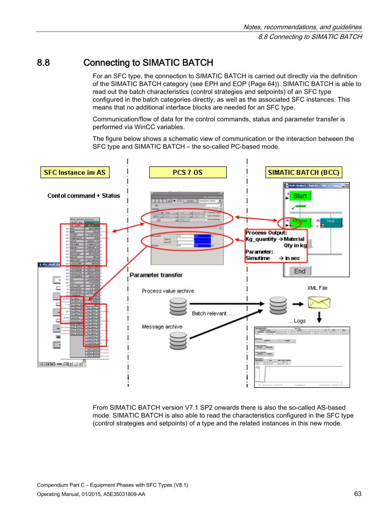
Notes, recommendations, and guidelines 8.8 Connecting to SIMATIC BATCH
Compendium Part C – Equipment Phases with SFC Types (V8.1) Operating Manual, 01/2015, A5E35031809-AA 63
8.8 Connecting to SIMATIC BATCH For an SFC type, the connection to SIMATIC BATCH is carried out directly via the definition of the SIMATIC BATCH category (see EPH and EOP (Page 64)). SIMATIC BATCH is able to read out the batch characteristics (control strategies and setpoints) of an SFC type configured in the batch categories directly, as well as the associated SFC instances. This means that no additional interface blocks are needed for an SFC type.
Communication/flow of data for the control commands, status and parameter transfer is performed via WinCC variables.
The figure below shows a schematic view of communication or the interaction between the SFC type and SIMATIC BATCH – the so-called PC-based mode.
From SIMATIC BATCH version V7.1 SP2 onwards there is also the so-called AS-based mode. SIMATIC BATCH is also able to read the characteristics configured in the SFC type (control strategies and setpoints) of a type and the related instances in this new mode.
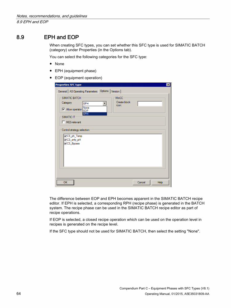
Notes, recommendations, and guidelines 8.9 EPH and EOP
Compendium Part C – Equipment Phases with SFC Types (V8.1) 64 Operating Manual, 01/2015, A5E35031809-AA
8.9 EPH and EOP When creating SFC types, you can set whether this SFC type is used for SIMATIC BATCH (category) under Properties (in the Options tab).
You can select the following categories for the SFC type:
● None
● EPH (equipment phase)
● EOP (equipment operation)
The difference between EOP and EPH becomes apparent in the SIMATIC BATCH recipe editor. If EPH is selected, a corresponding RPH (recipe phase) is generated in the BATCH system. The recipe phase can be used in the SIMATIC BATCH recipe editor as part of recipe operations.
If EOP is selected, a closed recipe operation which can be used on the operation level in recipes is generated on the recipe level.
If the SFC type should not be used for SIMATIC BATCH, then select the setting "None".
Notes, recommendations, and guidelines 8.10 Multiple instances of a type in a unit
Compendium Part C – Equipment Phases with SFC Types (V8.1) Operating Manual, 01/2015, A5E35031809-AA 65
8.10 Multiple instances of a type in a unit From SIMATIC BATCH version 8.1, multiple instances of the same SFC type can be addressed within a unit. In order to distinguish between several block instances of an SFC type within a unit, the block instance names have to be different.
Up to version V8.1 of SIMATIC BATCH, configurations with more than one instance of a function or operation type within a unit were rejected with a plausibility error during the compilation or merging of batch instances.
8.11 Closing lockout, start disable for SIMATIC BATCH It is possible to disable or interlock the start of an equipment module from SIMATIC BATCH via input "BA_EN = FALSE".
If the EM is then enabled for SIMATIC BATCH (BA_EN = TRUE), the recipe procedure can continue to be executed with "Resume".
8.12 Start and resumption lock for SIMATIC BATCH for equipment module previously started manually
From SIMATIC BATCH V8.1 onwards, each manual start of an SFC creates the same status information as those that are started automatically. This therefore ensures that all manual commands create the same status information as those that were started automatically by the control recipe. The functionality is implemented and cannot be turned off. Each status event for equipment phases and operations generates a message on the PCS 7 OS. These messages form part of the batch report.
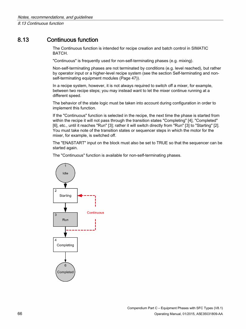
Notes, recommendations, and guidelines 8.13 Continuous function
Compendium Part C – Equipment Phases with SFC Types (V8.1) 66 Operating Manual, 01/2015, A5E35031809-AA
8.13 Continuous function The Continuous function is intended for recipe creation and batch control in SIMATIC BATCH.
"Continuous" is frequently used for non-self-terminating phases (e.g. mixing).
Non-self-terminating phases are not terminated by conditions (e.g. level reached), but rather by operator input or a higher-level recipe system (see the section Self-terminating and non-self-terminating equipment modules (Page 47)).
In a recipe system, however, it is not always required to switch off a mixer, for example, between two recipe steps; you may instead want to let the mixer continue running at a different speed.
The behavior of the state logic must be taken into account during configuration in order to implement this function.
If the "Continuous" function is selected in the recipe, the next time the phase is started from within the recipe it will not pass through the transition states "Completing" [4], "Completed" [6], etc., until it reaches "Run" [3]; rather it will switch directly from "Run" [3] to "Starting" [2]. You must take note of the transition states or sequencer steps in which the motor for the mixer, for example, is switched off.
The "ENASTART" input on the block must also be set to TRUE so that the sequencer can be started again.
The "Continuous" function is available for non-self-terminating phases.