Embed Size (px)
Citation preview
Comparison of Ultra-fast Microwave Sintering and
Conventional Thermal Sintering in Manufacturing of Anode
Support Solid Oxide Fuel Cell
Zhenjun Jiao1 , Naoki Shikazono*1 , Nobuhide Kasagi2
1. Institute of Industrial Science, the University of Tokyo 4-6-1 Komaba, Meguro-ku, Tokyo.
153-8505, Japan
2. Department of Mechanical Engineering, The University of Tokyo, Bunkyo-ku, Tokyo 113-8656,
Japan
Abstract
Ultra-fast microwave sintering in a multi-mode domestic microwave oven with selec-
tive susceptor and spacer has been proved to be an effective and facile method in the
manufacturing of anode support solid oxide fuel cell. Two anode support SOFCs were
fabricated by using ultra-fast microwave sintering and conventional thermal sintering
techniques, separately. The performances of the two cells were measured and compared
in a temperature range of 700oC to 800oC. The microstructures of the two cells after
the measurements were compared qualitatively based on SEM images. FIB-SEM tech-
nique was used to reconstruct the 3-D microstructure of both anode and cathode. The
quantitative comparison of 3-D reconstructions shows the application potential and the
advantages of microwave technique in SOFCs manufacturing.
Key words: Microwave, 3-D reconstruction, SOFC, TPB, Ponderomotive force ;
1. Introduction
As one of the most promising electric power conversion systems, solid oxide fuel cell
(SOFC) has been identified as an attractive efficient device for the electrochemical energy
conversion in the recent few decades. SOFC working in a high-temperature environment
Email address: [email protected] (Naoki Shikazono*1)
Preprint submitted to Elsevier June 22, 2010
is attracting more attention because of its fuel flexibility, high efficiency and low pol-
lution. In order to achieve long time stability and reducing the equipment cost of the
power conversion system, low temperature anode-support SOFC has been investigated
by many researchers with an emphasis on reducing the thickness of electrolyte, which
dominants the fuel cell resistance. As a result, anode support SOFC attracts more at-
tention because of its high power density with very thin electrolyte [2].
The fabrication of thin film electrolyte onto anode substrate is a challenging proce-
dure in the manufacturing of the whole cell. Zhang et al. [3] reported a novel method
for fabricating thin film electrolyte. In their experimental procedures, 10 µm-thick YSZ
(yttria stabilized zirconia) film was fabricated onto an anode substrate by revolving a
rod at low rotation speed. Their cell shows a maximum power density of 1.4 Wcm−2
at 800oC. The anode substrate with thin film electrolyte is sintered at a temperature of
1400oC, and the cathode screen-printed on the electrolyte layer is sintered at a tempera-
ture of 1200oC. For most of the researchers, the investigations of SOFC mainly focus on
electrode materials and their fabrication processes, and all the cells are sintered by the
conventional heating method. Few papers were published on the new techniques for cell
sintering.
Compared to the conventional sintering method which is time-and-energy consum-
ing, some researchers have shown the possibility of using microwave for rapid sintering
[4, 5]. Microwave heating is a self-heating process which is accomplished by absorbing
electromagnetic energy by a dielectric material. Higher heating rate and efficiency can
be obtained by using microwave volumetric heating. The energy absorbed by a dielec-
tric material per volume is estimated as P = 1
2ε0ε
′′ωE2V [4], where E is the electrical
field strength, ε0 is the dielectric constant in a vacuum, ε′′ is the dielectric loss factor
of the material, ω is the angular frequency of the external electromagnetic field and V
is the material volume. At room temperature, most of the ceramics have low dielectric
2
loss factor so that it is impossible to raise the temperature. Susceptors made by special
material with large dielectric loss coefficient are needed as a pre-heater to raise temper-
ature to the critical value beyond which the material to be sintered can be self-heated [4].
In microwave sintering process, the material volumetric heating mechanism makes
the sintering process rapid and selective. Fujitsu et al. [4] successfully used microwave
energy to achieve the sintering of stabilized zirconia in a 2.45-GHz multimode microwave
furnace with selective susceptors. The full sintering temperature of zirconia was reduced
by 100-150oC as compared to the conventional thermal sintering, and a finer grain size
was obtained. In a review of this technique, Clark [6] summarized the fundamentals,
benefits, and major research issues of microwave processing of materials.
Microwave heating offers an ultra-fast method for ceramic with an ultra-large heating
rate. The grain size uniformity increases because of a few orders higher densification rate
in a short sintering time. Only a few groups have investigated the use of microwave sinter-
ing in manufacturing SOFC. Oh et al. [7] used GDC(gadolia doped ceria) as electrolyte
and performed microwave sintering for SOFC, which clearly demonstrated the merits of
microwave sintering such as lower processing temperature and rapid thermal treatment.
The microwave-sintered cell exhibited higher peak power density at 650oC compared to
conventional sintered cell with the same materials. In the paper, no systematical work
was introduced on the manufacturing procedures and the microstructures comparison
between microwave-sintered and thermal-sintered cells. The only information which was
reported is the sintering time, i.e. one hour for anode-electrolyte co-sintering and one
hour for cathode sintering.
Details of the manufacturing procedures of both microwave-sintered and thermal-
sintered SOFCs have already been introduced in our previous paper [1]. Much shorter sin-
tering time was applied in the fabrication process, i.e. ten minutes for anode-electrolyte
3
co-sintering and ten minutes for cathode sintering. In this paper, further compari-
son is conducted between microwave-sintered and conventional thermal-sintered cells
on their performances and microstructures. With the same anode and cathode materi-
als used, quantitative comparison of the cell performances and microstructures between
microwave-sintered cell and thermal-sintered cell shows the application potential of mi-
crowave technique in SOFC manufacturing.
2. Experimental
2.1. Cell fabrication
Mechanically mixed NiO powder and YSZ powder (AGC Seimi Chem. Corp., Japan)
were used to prepare NiO-YSZ anode substrate pellets. The powders were mixed at
a ratio of 60 : 40 vol%. In order to maintain a sufficiently porous structure, 10wt%
organic pore former was added to the powder mixture. The final mixed powder was
uniaxial compressed in a metal die at 150 MPa pressure to make anode substrate pellets
with a diameter of 20 mm and a thickness of 0.7 mm. The pellets obtained were then
pre-sintered at 1200oC for 2 hours in a conventional sintering furnace to improve the
mechanical strength.
Microwave susceptor pellets were prepared before the microwave sintering experi-
ments. The microwave susceptor pellets (30 mm in diameter, and 3 mm in thick-
ness) were made by the same technique as substrate pellets, while the material used
is 72.5ZnO-27MnO2-0.5Al2O3 (ZMA, hereafter). ZMA was prepared by mixing zinc ox-
ide, manganese dioxide and alumina powders (High Purity Chemical Laboratory, Japan)
[4]. Spacer pellets (20 mm in diameter, and 0.8mm in thickness) were made by die-
pressing YSZ powder (0.3 µm, Tosoh Co, Japan) and then sintered in furnace at 1350oC
for 2 hours. The spacers were used between the cell and the ZMA susceptor to prevent
4
contamination.
The thin film electrolyte was dip-coated onto the substrate pellets. The coating slurry
was prepared by YSZ(8mol% yttria stabilized zirocnia) powder (Tosoh Co., Japan). A
mixture of isopropyl alcohol and terpineol was used as solvent, while ethyl cellulose was
used as an organic binder. The organic binder was mixed with YSZ powder first, then
added into the solvent. The slurry was ball-mixed for 24 hours to obtain a homogeneous
slurry, which contains 0.33 g solid per micro liter slurry.
After dip-coating, the pellets were dried in the air for 24 hours, and then divided into
two groups. The coated pellets in the first group were sintered in a multimode domestic
microwave oven (SHARP, RE-T31, 700 W). The anode substrate pellet was sandwiched
by two YSZ spacer pellets and then they were sandwiched by another two ZMA suscep-
tor pellets. The pellets series was then put into a fibrous alumina-silica case (Kaowool
1700 Board, Isolite Insulating Products Co. Ltd., Japan) for thermal insulation. The
insulation case was then put at the center of the turning table with a kaowool board as
spacer between the case and the glass table. The power was turned to 700 W and the
cell was sintered for 10 minutes and then cooled down for 1 hour at room temperature.
The coated pellets in the second group were sintered in conventional thermal heating
oven (MSTR16-430) at 1400oC for 3 hours, with the temperature heating up and cooling
down rate at 10oCmin−1, as standard reference cells.
Pure La0.8Sr0.2MnOx (LSM) powder (0.4 µm) was used as cathode material in this
study. The powder was then mixed with the terpineol solvent and the ethyl-cellulose
binder in agate mortar to obtain cathode printing paste. The LSM paste was then screen-
printed onto electrolyte film for the two groups. The first group with cathode printed was
sintered in microwave oven for 10 minutes, with an effective area of 28.26 mm2. For cath-
ode sintering, only one ZMA susceptor with one YSZ spacer was applied as the sintering
5
base to reduce the sintering temperature. The second group was sintered at 1150oC for
3 hours, with the temperature heating up and cooling down rate at 3.3oCmin−1.
2.2. Cell performance measurement devices
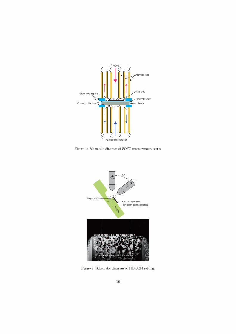
The SOFC performance measurement setup is shown in Fig. 1. Pt meshes was used
as current collectors, which were pressed against the electrodes of the cell by mechani-
cal force. Glass rings were used as the gas seals between two outer alumina tubes, and
the two outer tubes were also pressed against the cell by spring. After the temperature
was increased beyond 600oC, the glass seals melted and resulted in perfect gas seal-
ing. The performance of SOFC was evaluated at different temperatures by introducing
humidified H2 to anode as fuel, and pure oxygen to cathode as oxidant. For both hy-
drogen and oxygen, the gas flow rates were kept at 50 sccm. i-V characterization and
anode-cathode(A-C) impedance (frequency range 1− 106 Hz, AC signal stength 10 mV)
measurements were conducted with a Solartron frequency analyzer (1255B) and a So-
lartron interface.
2.3. Image processing and 3-D reconstruction
Image observation and quantification of the sample microstructures after measure-
ments were facilitated by FIB-SEM (Carl Zeiss, NVision 40, Germany). The system is
equipped with Gemini FE-SEM column, zeta FIB column and a multi-channel gas injec-
tion system (SIINT). 3-D microstructures of both anode and cathode can be virtually
reconstructed in a computional field by using 2-D SEM images obtained through the
FIB-SEM observation, which is shown in Fig. 2 [8, 10]. Cross-section of the observed
sample was first polished by Ar-ion beam cross-section polisher (JEOL Ltd., SM-09010,
Japan), which results in less damage and smoother cross section compared to the dia-
mond slurry polishing. A layer of carbon was then deposited onto polished surface to
indicate the reconstructed region. All the 2-D images were processed in software Matlab
6
for the subsequent reconstruction of 3-D structure in software Avizo (Maxnet Co. Ltd.,
Japan). The quantitative comparison between microwave-sintered and thermal-sintered
cells was based on their corresponding 3-D reconstruction.
3. Results and discussion
3.1. Experimental results
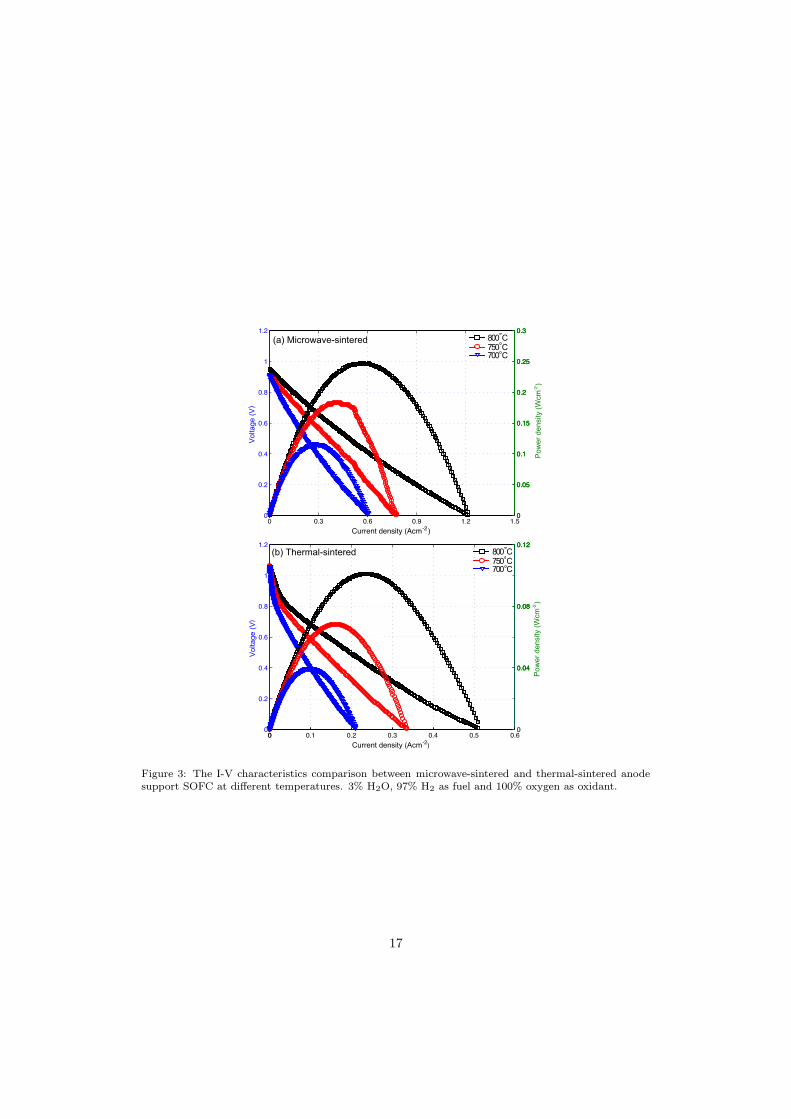
Fig. 3 shows the comparison of i-V performances between microwave-sintered and
conventional thermal-sintered cells. It is shown that the maximum power densities are
0.12, 0.18 and 0.25 Wcm−2 for microwave-sintered cell and 0.04, 0.07 and 0.11 Wcm−2 for
thermal-sintered cells at 700oC, 750oC and 800oC, respectively. The anode-cathode open
circuit potential of microwave-sintered cell is around 0.95 V, which is lower than the the-
oretical value 1.14 V. The lower open circuit potential indicates the possibility of certain
leakage across the thin YSZ film, which is caused by micro-cracks formed in the ultra-
fast microwave sintering process. Besides, the non-uniform electromagnetic field within
domestic microwave oven may also lead to the micro-cracks within non-uniform sintering
process [1]. Without gas leakage problem, the performance of microwave-sintered cell
can be further improved.
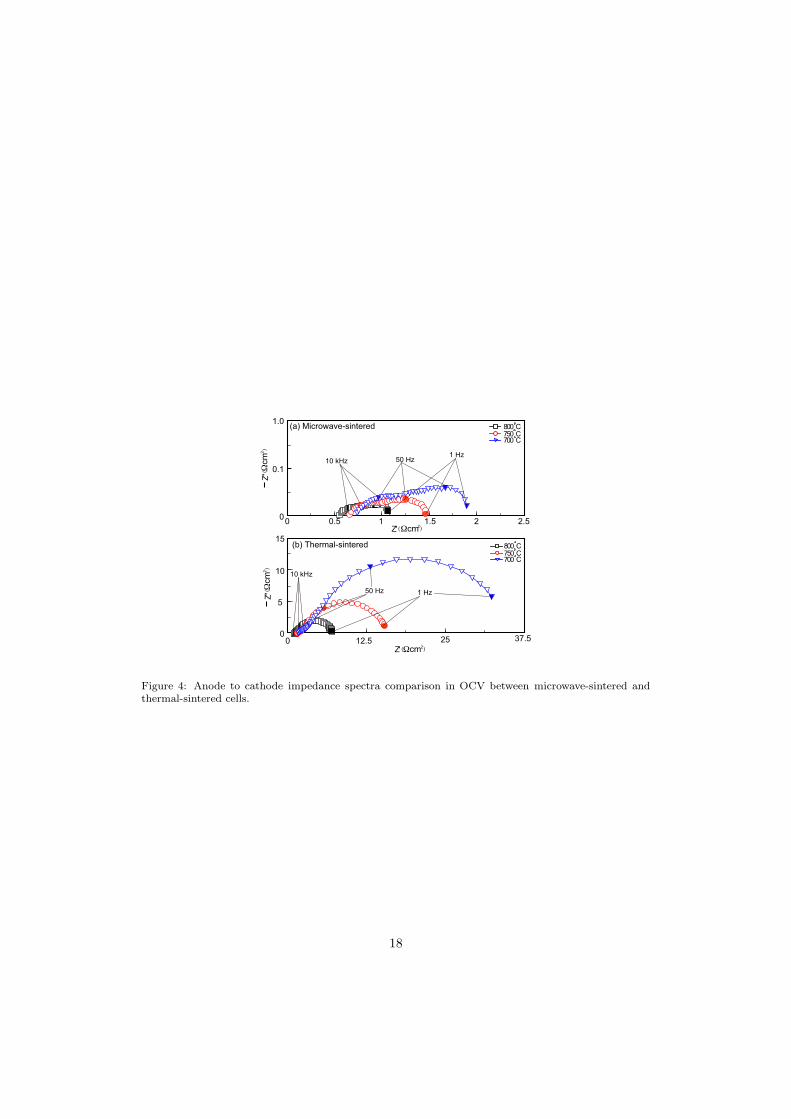
Fig. 4 shows the comparison of anode-cathode impedance spectra between microwave-
sintered and conventional thermal-sintered cells. According to the high frequency spectra,
the ohmic resistance of the cell sintered by microwave was about 0.55 Ωcm2 at 800oC
which is only half of thermal-sintered cell. With the increase of temperature, the ohmic
resistance slightly increases in both cases. From 800oC to 700oC, for microwave-sintered
cell, the electrode polarization increases from 0.5 Ωcm2 to 1 Ωcm2, while for thermal-
sintered cell, the increase is from 5.5 Ωcm2 to about 31.5 Ωcm2. Both of the impedance
changes indicate that low-frequency polarization dominates the cell performance, espe-
cially for thermal-sintered cell. The initial electrochemical behavior of pure LSM cathode
7
has been studied by Jiang et al. [11] at 900oC, which showed that pure LSM always pre-
sented very high activation polarization in the initial state (5.5 Ωcm2), which is close
to our data. After 3 hours cathodic current passage of 0.2 Acm−2, the interface polar-
ization was reduced to 2.1 Ωcm2. For microwave-sintered cell, much smaller activation
polarization (0.5 Ωcm2) were obtained at 800oC.
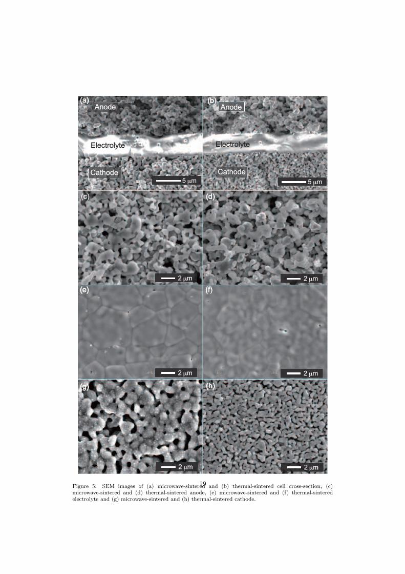
The microstructures of the cells after testing were examined by SEM. Fig. 5 shows the
SEM images of cross-sections, and the top surfaces of anodes, electrolytes and cathodes
for both microwave-sintered and thermal-sintered cells. From the comparison it can be
observed that, with the same materials used, microwave sintering results in very different
microstructures from thermal sintering method. After sintering, microwave-sintered cell
remained flat while thermal-sintered one was bent. Several cells were tested, and simi-
lar deformations were obtained. For anode, microwave sintering method produces finer
and sharper particles than thermal sintering. For cathode, microwave sintering produced
coarser LSM particle than thermal sintering. Certain amount of sub-micron particles
was distributed uniformly on the LSM particle surface.
3.2. 3-D reconstructions
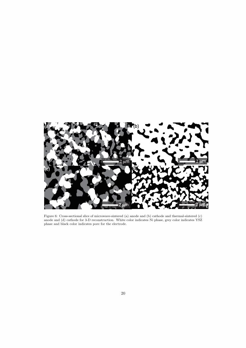
Fig. 6 shows the 2-D slice images of microwave-sintered and thermal-sintered anode
and cathode cross-sections. Based on series of sliced images, anode and cathode can be
reconstructed in 3-D [8]. It is obviously observed that microwave sintering results in more
dense and finer composite anode microstructure and much coarser particle for cathode.
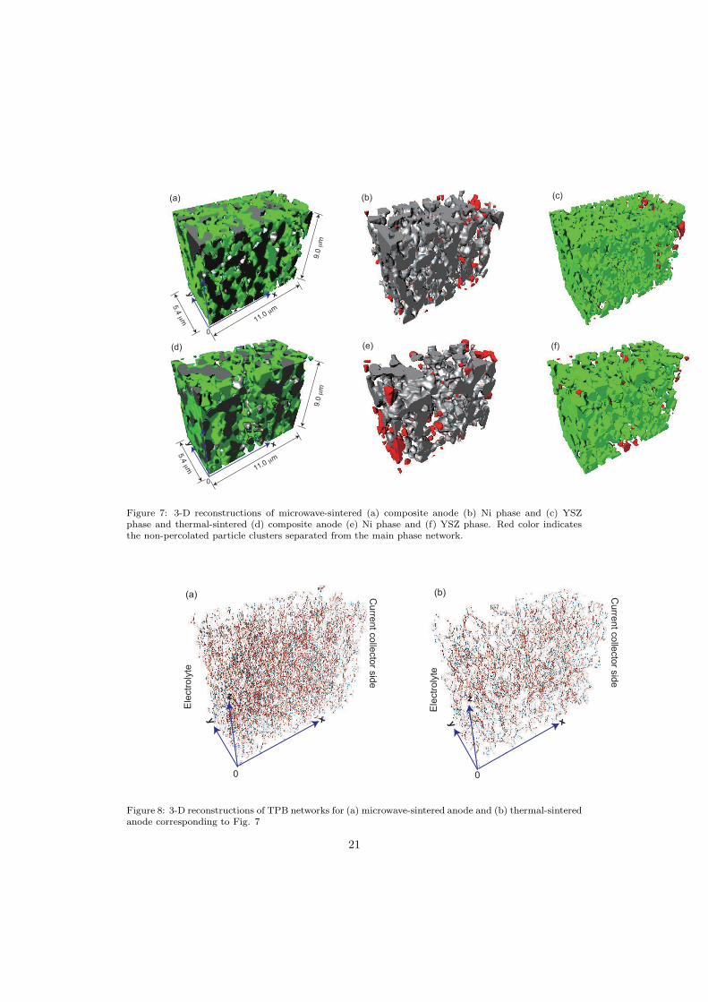
Fig. 7 shows the 3-D reconstruction of the microstructures for both microwave-sintered
and thermal-sintered anodes, with separated Ni and YSZ phases. In the reconstructions,
x and y axis have been indicated in Fig. 2 and z axis is perpendicular to x−y plane along
which image slices are subsequently aligned. Non percolated clusters in both Ni and YSZ
networks are shown in red color. The connectivities of both Ni and YSZ phases networks
are measured by the volume percentage of the percolated cluster. The microstructural8
parameters are summarized in Table 1. From the comparison, it can be seen that, with
a much shorter sintering time and lower sintering temperature [4], microwave sintering
method produces more dense composite anode structure with better phase connections
for both Ni and YSZ.
In order to further investigate the anode microstructural differences between mi-
crowave sintering and thermal sintering methods, TPB networks corresponding to Fig. 7
was reconstructed as shown in Fig. 8. Centroid method was used to calculate the TPB
densities [9]. TPB density is defined as the length of TPB within unit volume. The
total TPB densities and active TPB densities in different directions for both cells are
listed in Table 2. It is shown that microwave sintering results in larger total TPB den-
sity than thermal sintering, which is due to finer particle size. Only active TPB, which
connects current collector to electrolyte, contributes to cell performance. The active
TPB densities along three axis directions are nearly the same, which means that both
microwave sintering and thermal sintering produce isotropic anode microstructures. The
active TPB density takes possession of 78% of the total density for microwave-sintered
anode and 72% for thermal-sintered anode. The higher total TPB density and active
TPB density of microwave-sintered anode can partially explain the better performance
and lower polarization of microwave-sintered cell.
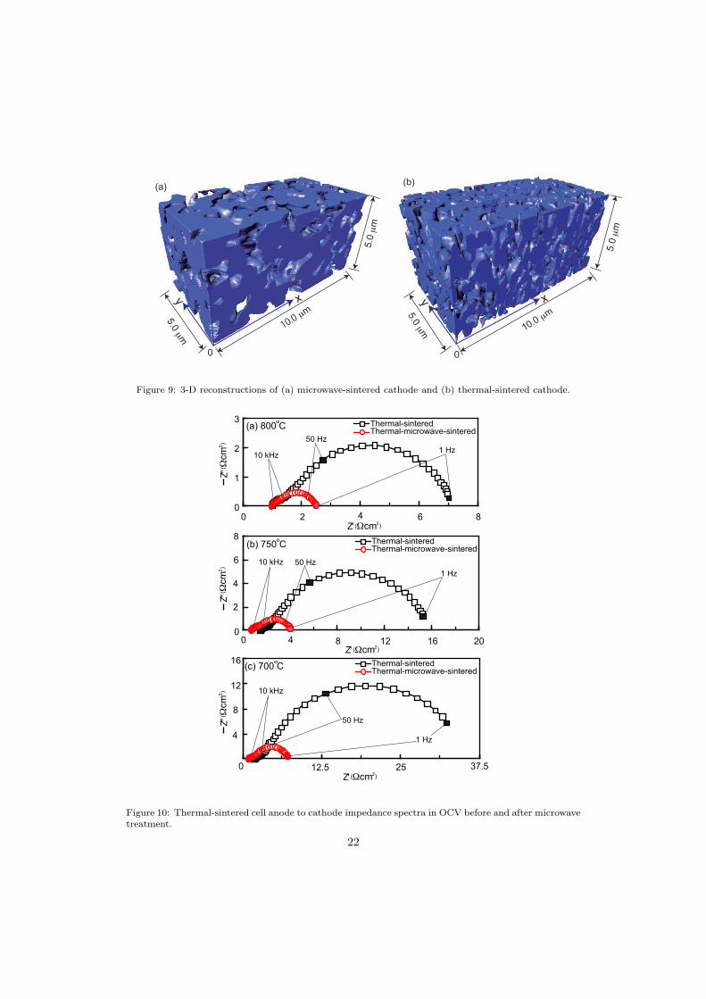
Fig. 9 shows the 3-D reconstructions of microwave-sintered and thermal-sintered
cathodes. The corresponding porosities for two cathodes are shown in Table 1. It is
evident that microwave sintering results in much coarser LSM particle than thermal
sintering. This can be explained by the higher sintering temperature and non-thermal
driving force, which can enhance thermal sintering [6]. For pure LSM cathode, TPB
concentrates at the interface between cathode and electrolyte and the 2-D TPB densities
of two cells are shown in Table 2. It is seen that thermal sintering leads to more than
twice TPB density than microwave sintering method, which can not explain the better
9
performance of the microwave-sintered cell.
Jiang et al. [12, 13] proved that the initial large polarization behavior of freshly pre-
pared LSM cathode is originated from the enrichment of passivation species such as SrO
and MnOx on the LSM particle surface layer. SrO and MnOx could occupy the active
sites and inhibit the surface dissociation and diffusion of oxygen. Cathodic polarization
as well as acid etching has been proved to be able to effectively remove or decrease the
passivation species from the active sites on LSM surface. The significant improvement
of the initial cathode performance caused by the two methods have been proven to re-
duce the initial cathodic polarization to less than one tenth of the original value, with
constant TPB density. Lee et al. [14] investigated the active reaction sites for oxygen
reduction in LSM/YSZ electrodes. Surface oxide vacancies as well as the TPB sites are
active in oxygen reduction process. TPB sites are favored since additional diffusional
processes are required for the former sites. At lower oxygen pressure, the TPB domi-
nates the surface reaction while the contribution from the surface sites becomes more
important at higher oxygen pressure (1 atm). With high oxygen pressure, surface grain
boundary diffusion in porous electrode can not be ignored for its contribution to oxygen
reduction, since diffusion in grain boundary is much faster than bulk diffusion. Adler
[15] summarized the factors governing oxygen reduction in SOFC cathode. The cathode
performance is limited by at least four physical processes: adsorption of oxygen, ambipo-
lar diffusion(defined as the diffusion of positive and negative particles in a plasma at the
same rate due to their interaction via the electric field) transport to solid-solid interface,
interfacial electrochemical kinetics and ionic transport in the ionic sub-phase, among
which TPB density can only dominate the interfacial electrochemical kinetics. With
high oxygen pressure, the other three process may become the rate-determine process
and dominate the cathode performance with TPB density. In microwave sintering, the
non-thermal effect may result in crystal structure change to the material and influence
the final performance of cathode. In our experiments, oxygen inlet pressure was set at 1
10
atm, which means that grain boundary of LSM also contributes to the cathodic oxygen
reduction process, which may even dominate the cathode performance. Even with lower
2-D TPB density at cathode-electrolyte interface, microwave-sintered cathode can show
better performance if the concentration of the active surface sites is higher.
In microwave sintering, once the material is heated to a critical temperature via
susceptor, the material can be self-heated. Above the critical temperature, the ionic
mobility becomes large enough for the ceramic ions near surface layer to absorb microwave
energy and causes dielectric loss due to the ionic movement. Microwave then can interact
with ceramic surface through either surface polarization or conduction processes driven
by ponderomotive force(Fp) [6, 16]. In microwave driving surface polarization process,
the high frequency ion oscillation results in microwave-excited ion current which may
result in similar effects as normal electrical current passing through LSM in cathodic
polarization. The initial large cathode polarization then can be reduced by microwave
driving surface polarization. For the conduction process of mobile ions, ponderomotive
force is then defined. Ponderomotive force is defined as a nonlinear force that a charged
particle experiences in an inhomogeneous oscillating electromagnetic field [17], which is
expressed as,
Fp = −
e2
4mω2∆E2 (1)
where e is the electrical charge of the particle, m is the ion mass, ω is the angular
frequency of oscillation of the field, and E is the amplitude of the electric field. This
equation shows that a charged particle in an inhomogeneous oscillating field not only
oscillates at the frequency but also drifts toward the weak field area. It is known that
the sign of the particle charge does not change the direction of the ponderomotive force.
Ponderomotive force is thus an electromagnetic force, which is able to move mass. Mi-
crowave presents the largest amplitude at ceramic surface and dissipate to zero into the
ceramic bulk with a depth of nanometer scale [17]. In the interacting process, all kinds of
11
mobile ions at ceramic surface experience a relatively large ponderomotive driving force
towards the ceramic bulk. With this mechanism, continuing crystal vacancies are driven
towards the ceramic surface in an opposite direction. The increasing concentration of
vacancy may create more active oxygen adsorption sites on LSM surface and then reduce
the initial cathodic polarization. At the same time, microwave induced vacancy move-
ment at high temperature may also enhance the thermal sintering process, which leads
to much coarser microstructure in a short sintering time.
In order to prove the improvement of LSM cathode in microwave sintering, another
experiment was conducted. A thermal-sintered cell was sintered again in microwave
with one-side susceptor and spacer used. The cell impedances comparison between the
thermal-microwave-sintered cell and thermal-sintered cell is shown in Fig. 10. From
the comparison, it is obvious that cell polarization is reduced compared to the initial
thermal-sintered cell, which proves that microwave sintering process have the similar ef-
fect as current passage in cathodic polarization process. The lower sintering temperature
with one-side susceptor make it reasonable to ignore the microwave sintering influence on
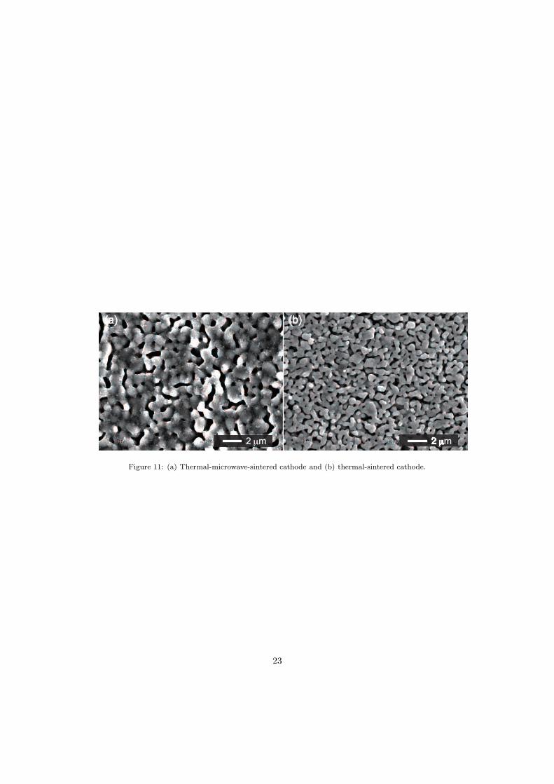
anode side. The SEM image of thermal-microwave-sintered cathode and purely thermal-
sintered cathode are compared in Fig. 11. The thermal-microwave-sintered cathode
presents coarser microstructure with a state in between microwave-sintered and thermal-
sintered cathodes. The coarsening of cathode proves that TPB does not dominate the
cell performances, but the surface active sites.
Besides the initial performances, the cell durabilities have been tested for both cells.
Microwave-sintered cell showed very stable performance in a 140 hours discharging pro-
cess while thermal-sintered one showed unstable performance and even sudden failing
at 20 hours. Details of the durability tests will be shown in the next paper. In the fu-
ture, specially designed microwave oven can be used for fabricating planar anode support
SOFC to improve the cell quality and meet all the practical manufacturing requirements,
12
such as heating program, SOFC size, materials and so on. With uniform electromag-
netic field and controllable power output, the gas leakage problem can be solved. For
the cell fabricated by thermal sintering, it can also be processed in microwave to im-
prove the cathode performance. Further investigation should be conducted to explain
the advantages of microwave sintering in cathode fabrication.
4. Conclusions
Anode support SOFCs were fabricated by both microwave-sintering and conventional
thermal-sintering methods. The cell performances in the intermediate temperature range
of 700−800oC were measured for both cells. Microwave-sintered cell shows higher initial
performance and lower polarization than thermal-sintered one. The reconstructed 3-D
structures were used to quantify anode and cathode microstructural parameters such as
porosity, percolation percentage and TPB densities. With a much shorter sintering time,
microwave sintering results in finer and sharper particles and higher TPB densities in
anode, but coarser particles and lower TPB density in cathode. The higher cell per-
formance is partially explained by the finer anode microstructure and the non-thermal
effect in the microwave sintering of cathode. The non-thermal effect in microwave sinter-
ing of cathode is caused by the enhancement of active surface sites for oxygen adsorption,
which is caused by the polarization effect of ponderomotive force. With ultra-fast sin-
tering process and much lower cathodic polarization, microwave can be applied in SOFC
manufacturing as a new technique with much higher efficiency compared to conventional
sintering process.
Acknowledgments
This work was supported by the New Energy and Industrial Technology Development
Organization (NEDO) under the Development of System and Elemental Technology on
Solid Oxide Fuel Cell (SOFC) Project.
13
References
[1] Z. Jiao, N. Shikazono, N. Kasagi, J. Power Sources 195 (2009) 151–154.
[2] S. P. S. Badwal, M. J. Bannister, R. H. J. Hannink, Science and Technology of Zirconia V, Technomic
publishing Company, 1993.
[3] Y. Zhang, X. Huang, Z. Lu, Z. Liu, X. Ge, J. X. X. Xin, X. Sha, W. Su, J. Am. Ceram. Soc. 89
(2006) 2304–2307.
[4] S. Fujitsu, M. Ikegami, T. Hayashi, J. Am. Ceram. Soc. 8 (2000) 2085–2087.
[5] M. A. Janney, C. L. Calhoun, H. D. Kimrey, J.Am. Ceram. Soc. 2 (1992) 341–346.
[6] D. E. Clark, Annu. Rev. Mater. Sci 26 (1996) 299–331.
[7] E. O. Oh, H. Kim, D. C. Baek, J. Park, H.-R. Kim, J.-H. Lee, H.-W. Lee, C. M. Whang, J.-W.
Son, ECS Transactions 7 (2007) 743–748.
[8] H. Iwai, N. Shikazono, T. Matsui, H. Teshima, M. Kishimoto, R. Kishida, D. Hayashi, K. Matsuzaki,
D. Kanno, M. Saito, H. Muroyama, K. Eguchi, N. Kasagi, H. Yoshida, J. Power Sources 195 (2010)
955–961.
[9] N. Shikazono, D. Kanno, K. Matsuzaki, H. Teshima, S. Sumino, N. Kasagi, J. Electrochem. Soc.
(2010) in press.
[10] J. R. Wilson, J. S. Cronin, A. T. Duong, S. Rukes, H.-Y. Chen, K. Thornton, D. R. Mumm,
S. Barnett, J. Power Sources 195 (2010) 1829–1840.
[11] Y. D. Zhen, S. P. Jiang, J. Electrochem. Soc. 12 (2006) A2245–A2254.
[12] S. P. Jiang, J. G. Love, J. P. Zhang, M. Hoang, Y. Ramprakash, A. E. Hughes, S. P. S. Badwal,
Solid State Ionics 121 (1999) 1–10.
[13] S. P. Jiang, J. G. Love, Solid State Ionics 138 (2001) 183–190.
[14] H. Y. Lee, W. S.Cho, S. M. Oh, H. D. Wiemhofer, W. Gopel, J. Electrochem. Soc. 142 (1995)
2659–2664.
[15] S. B. Adler, Chem. Rev. 104 (2004) 4791–4843.
[16] J. H. Booske, R. F. Cooper, S. A. Freeman, K. I. Rybakov, V. E. Semenov, Phys. Plasm. 5 (1998)
1664–1670.
[17] S. A. Freeman, J. H. Booske, R. F. Cooper, J. Appl. Phys. 83 (1998) 5761–5772.
14
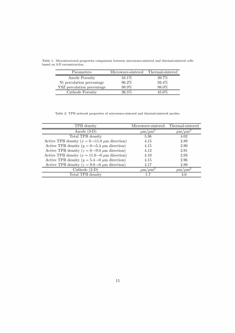
Table 1: Microstructural properties comparison between microwave-sintered and thermal-sintered cellsbased on 3-D reconstruction.
Parameters Microwave-sintered Thermal-sintered
Anode Porosity 34.1% 39.7%Ni percolation percentage 96.2% 93.4%
YSZ percolation percentage 98.9% 98.0%Cathode Porosity 36.5% 45.0%
Table 2: TPB network properties of microwave-sintered and thermal-sintered anodes.
TPB density Microwave-sintered Thermal-sintered
Anode (3-D) µm/µm3 µm/µm3
Total TPB density 5.36 4.02Active TPB density (x = 0→11.0 µm direction) 4.15 2.89Active TPB density (y = 0→5.4 µm direction) 4.15 2.90Active TPB density (z = 0→9.0 µm direction) 4.12 2.91Active TPB density (x = 11.0→0 µm direction) 4.10 2.93Active TPB density (y = 5.4→0 µm direction) 4.15 2.96Active TPB density (z = 9.0→0 µm direction) 4.17 2.89
Cathode (2-D) µm/µm2 µm/µm2
Total TPB density 1.7 4.0
15
Current collector
Glass sealing ring Cathode
Electrolyte film
Alumina tube
Oxygen
Humidified hydrogen
Anode
Figure 1: Schematic diagram of SOFC measurement setup.
SEM
FIB
Sam
ple
54
Carbon deposition
Ion beam polished surface
Target surface
Ele
ctr
oly
te
Cross-sectional slice for reconstruction
0 x
y
Cu
rre
nt
co
lle
cto
r s
ide
Figure 2: Schematic diagram of FIB-SEM setting.
16
0 0.3 0.6 0.9 1.2 1.50
0.2
0.4
0.6
0.8
1
1.2
Current density (Acm-2 )
Vo
lta
ge
(V
)
0
0.05
0.1
0.15
0.2
0.25
0.3
0
0.05
0.1
0.15
0.2
0.25
0.3
0
0.05
0.1
0.15
0.2
0.25
0.3
0 0.1 0.2 0.3 0.4 0.5 0.60
0.2
0.4
0.6
0.8
1
1.2
Current density (Acm-2)
Vo
lta
ge
(V
)
00
0.04
0.08
0.12
Po
we
r d
en
sity (
Wcm
-2)
0
0.04
0.08
0.12
0.04
0.08
0.12
(b) Thermal-sintered
(a) Microwave-sintered 800 C750 C700 C
800 C750 C700 C
Po
we
r d
en
sity (
Wcm
-2)
Figure 3: The I-V characteristics comparison between microwave-sintered and thermal-sintered anodesupport SOFC at different temperatures. 3% H2O, 97% H2 as fuel and 100% oxygen as oxidant.
17
0 12.5 25 37.5
15
10
5
0
0 0.5 1 1.5 2 2.5
0.1
0
10 kHz 50 Hz
(b) Thermal-sintered
(a) Microwave-sintered
1 Hz
10 kHz
50 Hz 1 Hz
800 C750 C700 C
Z''
Ωcm
(2)
Z''
Ωcm
(2)
Z' Ωcm( 2)
800 C750 C700 C
Z' Ωcm( 2)
1.0
Figure 4: Anode to cathode impedance spectra comparison in OCV between microwave-sintered andthermal-sintered cells.
18
5 μm
2 μm 2 μm
2 μm 2 μm
2 μm 2 μm
(a) (b)
(c) (d)
(e) (f)
(g) (h)
Electrolyte Electrolyte
Anode Anode
Cathode Cathode
5 μm
Figure 5: SEM images of (a) microwave-sintered and (b) thermal-sintered cell cross-section, (c)microwave-sintered and (d) thermal-sintered anode, (e) microwave-sintered and (f) thermal-sinteredelectrolyte and (g) microwave-sintered and (h) thermal-sintered cathode.
19
2 μm
2 μm
(a)
(c)
2 μm
2 μm
(b)
(d)
Figure 6: Cross-sectional slice of microwave-sintered (a) anode and (b) cathode and thermal-sintered (c)anode and (d) cathode for 3-D reconstruction. White color indicates Ni phase, grey color indicates YSZphase and black color indicates pore for the electrode.
20
(a) (b) (c)
(e)(d) (f)
5.4
μm 11.0 μm
5.4
μm 11.0 μm
x
y
z
x
y
z
0
0
9.0
μm
9.0
μm
Figure 7: 3-D reconstructions of microwave-sintered (a) composite anode (b) Ni phase and (c) YSZphase and thermal-sintered (d) composite anode (e) Ni phase and (f) YSZ phase. Red color indicatesthe non-percolated particle clusters separated from the main phase network.
(a) (b)
Ele
ctr
oly
te
Cu
rren
t co
llecto
r sid
e
Cu
rren
t co
llecto
r sid
e
Ele
ctr
oly
te
0 0
xy
z
xy
z
Figure 8: 3-D reconstructions of TPB networks for (a) microwave-sintered anode and (b) thermal-sinteredanode corresponding to Fig. 7
21
(a)(b)
10.0 μ
m
x
5.0 μm
y
z
0
10.0 μm
xyz
0
5.0 μm
5.0
μm
5.0
μm
Figure 9: 3-D reconstructions of (a) microwave-sintered cathode and (b) thermal-sintered cathode.
0 4 8 12 16 20
8
6
4
2
0
16
12
8
4
0 2 4 6 8
3
2
1
0
Thermal-sinteredThermal-microwave-sintered
(a) 800 C
(b) 750 C
(c) 700 C
0 12.5 25 37.5
Z' Ωcm( 2)
Z' Ωcm( 2)
Z' Ωcm( 2)
Z''
Ωcm
(2)
Z''
Ωcm
(2)
Z''
Ωcm
(2)
Thermal-sinteredThermal-microwave-sintered
Thermal-sinteredThermal-microwave-sintered
10 kHz
50 Hz
1 Hz
10 kHz 50 Hz
1 Hz
10 kHz
50 Hz
1 Hz
Figure 10: Thermal-sintered cell anode to cathode impedance spectra in OCV before and after microwavetreatment.
22
2 μm
(b)
2 μm
(a)
Figure 11: (a) Thermal-microwave-sintered cathode and (b) thermal-sintered cathode.
23


![Microwave Sintering of Thermistor Ceramics · 2018. 9. 25. · Microwave Sintering of Thermistor Ceramics 87 3.1.2 Microwave sintering of NTC thermistor ceramics Jin et al.[12, 13]](https://img.pdfslide.us/doc/110x75/5fc1c5bde14383042a0edfab/microwave-sintering-of-thermistor-ceramics-2018-9-25-microwave-sintering-of.jpg)


![Mechanisms of Micro Structure Control in Conventional Sintering[1]](https://img.pdfslide.us/doc/110x75/55353c5d550346eb168b4660/mechanisms-of-micro-structure-control-in-conventional-sintering1.jpg)