Embed Size (px)
Citation preview
Microwave Assist Sintering of Porcelain Insulators with Large Cross-section
Shawn M. Allan*Morgana Fall, Dr. Holly Shulman, Ceralink Inc
Gary Carnahan, Lapp Insulator Company
Ceralink Inc. Rensselaer Technology Park
Troy, New York
33rd International Conference and Exposition onAdvanced Ceramics and Composites
Daytona Beach, FloridaJanuary 19, 2009
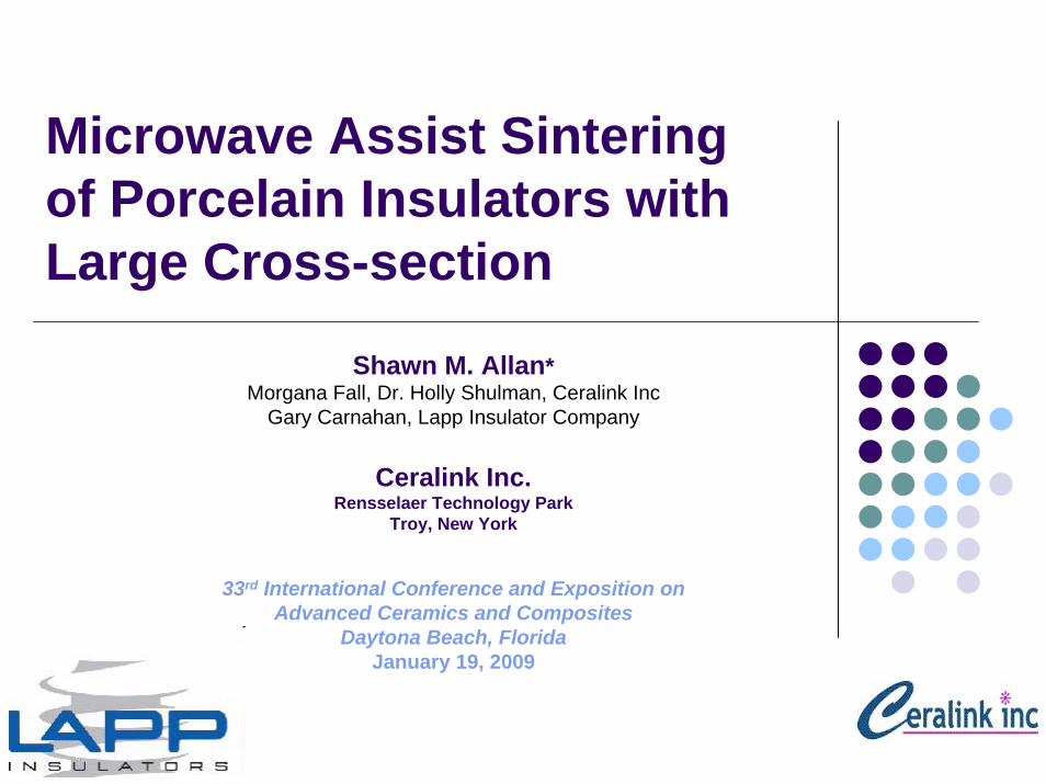
OutlineCeramic Processing
Microwave Assist Technology
Sintering of Porcelain Insulators
Summary
Ceralink 1700 °C MAT Lab Kiln 2.45 GHz
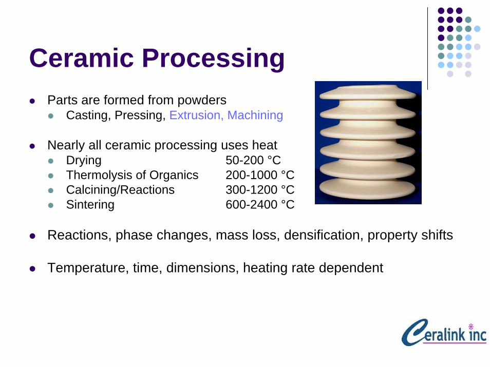
Ceramic ProcessingParts are formed from powders
Casting, Pressing, Extrusion, Machining
Nearly all ceramic processing uses heatDrying 50-200 °CThermolysis of Organics 200-1000 °CCalcining/Reactions 300-1200 °CSintering 600-2400 °C
Reactions, phase changes, mass loss, densification, property shifts
Temperature, time, dimensions, heating rate dependent
Ceramic Processing ReactionsIn firing Whitewares several types of reaction occur
Reactions can be endothermic or exothermic
Degassing: remove physically adsorbed gas (water, CO2)
Dehydration: kaolin metakaolin & waterAl2O3•2SiO2•2H2O Al2O3•2SiO2 + 2H2O (g)
Dissociation: CaCO3 CaO + CO2
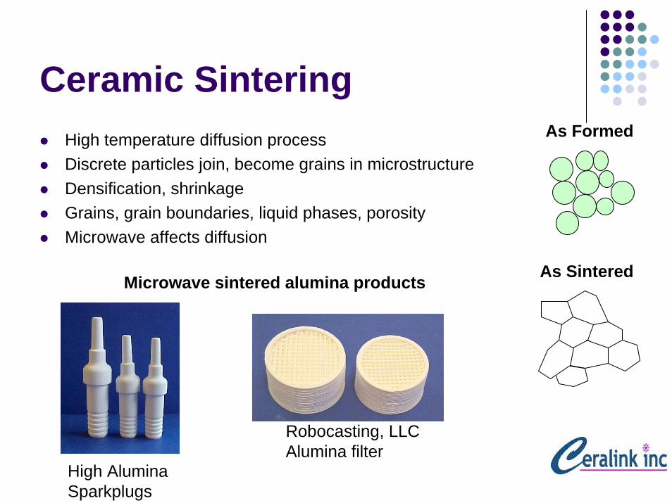
Ceramic SinteringAs FormedHigh temperature diffusion process
Discrete particles join, become grains in microstructureDensification, shrinkageGrains, grain boundaries, liquid phases, porosityMicrowave affects diffusion
As SinteredMicrowave sintered alumina products
Robocasting, LLCAlumina filter
High AluminaSparkplugs
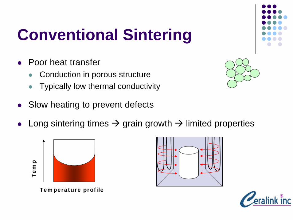
Conventional SinteringPoor heat transfer
Conduction in porous structureTypically low thermal conductivity
Slow heating to prevent defects
Long sintering times grain growth limited properties
Tem
p
Temperature profile
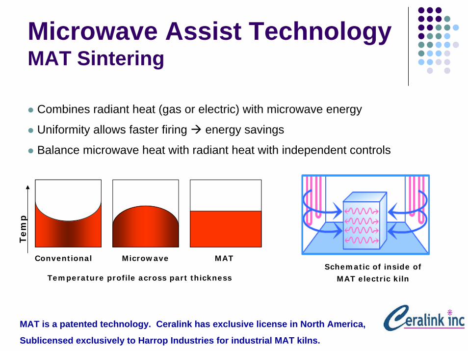
Microwave Assist TechnologyMAT Sintering
Combines radiant heat (gas or electric) with microwave energy
Uniformity allows faster firing energy savings
Balance microwave heat with radiant heat with independent controls
Schematic of inside of
MAT electric kiln
Tem
p
Conventional Microwave MAT
Temperature profile across part thickness
MAT is a patented technology. Ceralink has exclusive license in North America,
Sublicensed exclusively to Harrop Industries for industrial MAT kilns.
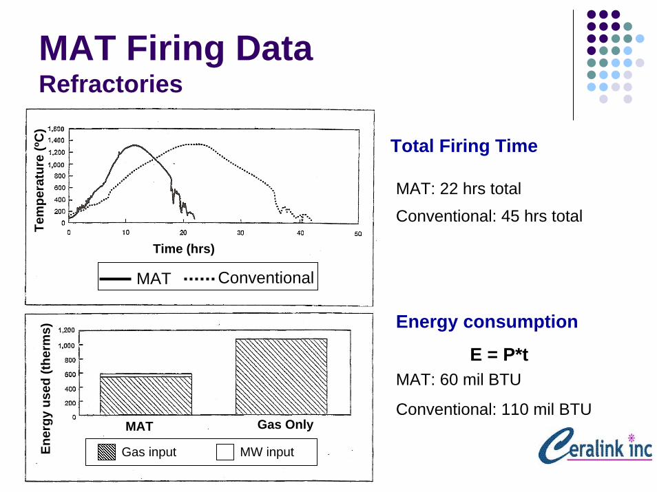
MAT Firing DataRefractories
Tem
pera
ture
(ºC
)En
ergy
use
d (th
erm
s)
MAT Gas Only
Time (hrs)
Gas input MW input
MAT Conventional
Total Firing Time
MAT: 22 hrs total
Conventional: 45 hrs total
Energy consumption
E = P*tMAT: 60 mil BTU
Conventional: 110 mil BTU
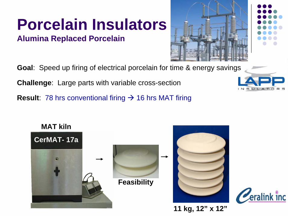
Porcelain InsulatorsAlumina Replaced Porcelain
Goal: Speed up firing of electrical porcelain for time & energy savings
Challenge: Large parts with variable cross-section
Result: 78 hrs conventional firing 16 hrs MAT firing
MAT kiln
CerMAT- 17a
Feasibility
11 kg, 12” x 12”
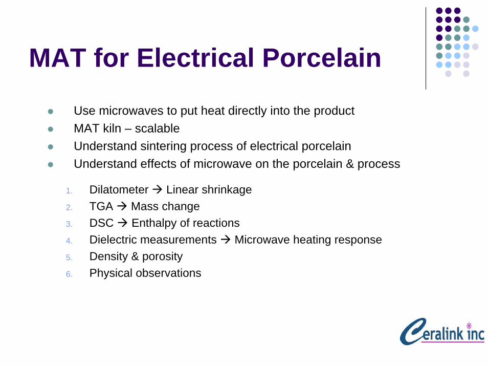
MAT for Electrical Porcelain
Use microwaves to put heat directly into the productMAT kiln – scalableUnderstand sintering process of electrical porcelainUnderstand effects of microwave on the porcelain & process
1. Dilatometer Linear shrinkage2. TGA Mass change3. DSC Enthalpy of reactions4. Dielectric measurements Microwave heating response5. Density & porosity6. Physical observations
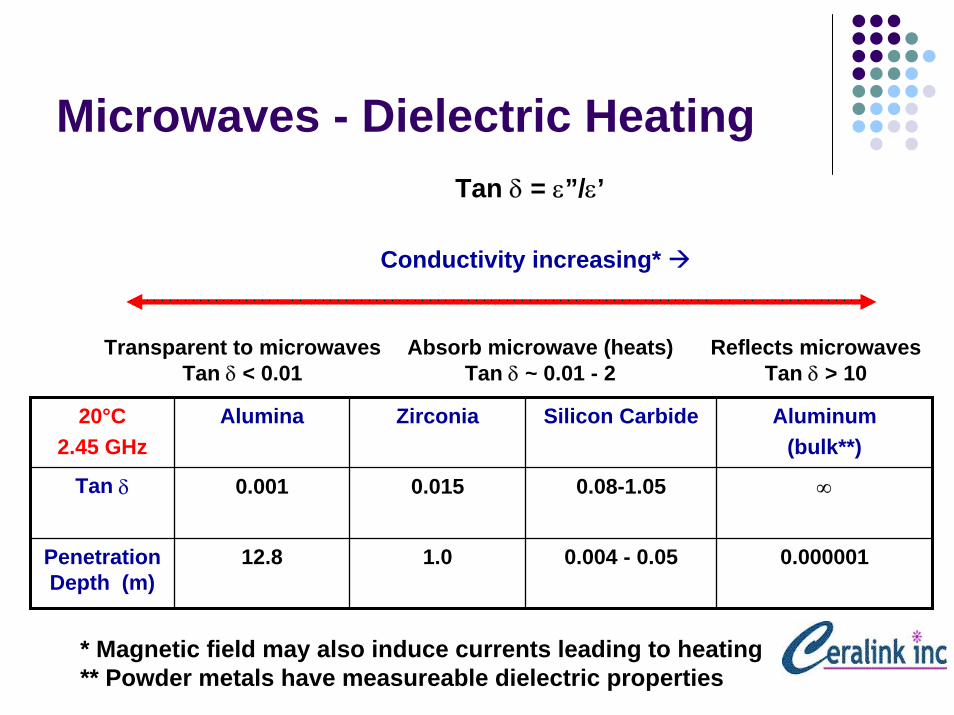
Microwaves - Dielectric HeatingTan δ = ε”/ε’
Conductivity increasing*
Transparent to microwavesTan δ < 0.01
Absorb microwave (heats)Tan δ ~ 0.01 - 2
Reflects microwavesTan δ > 10
20°C2.45 GHz
Alumina Zirconia Silicon Carbide Aluminum(bulk**)
Tan δ 0.001 0.015 0.08-1.05 ∞
Penetration Depth (m)
12.8 1.0 0.004 - 0.05 0.000001
* Magnetic field may also induce currents leading to heating** Powder metals have measureable dielectric properties
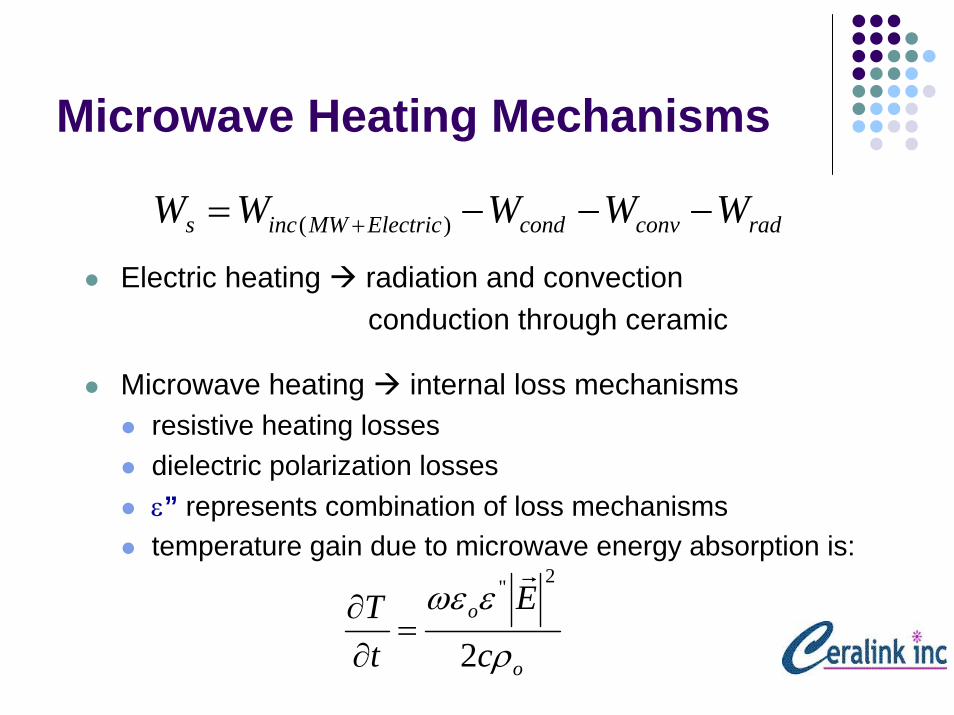
Microwave Heating Mechanisms
radconvcondElectricMWincs WWWWW −−−= + )(
o
o
c
E
tT
ρ
εωε
2
2"r
=∂∂
Electric heating radiation and convectionconduction through ceramic
Microwave heating internal loss mechanisms resistive heating lossesdielectric polarization lossesε” represents combination of loss mechanismstemperature gain due to microwave energy absorption is:
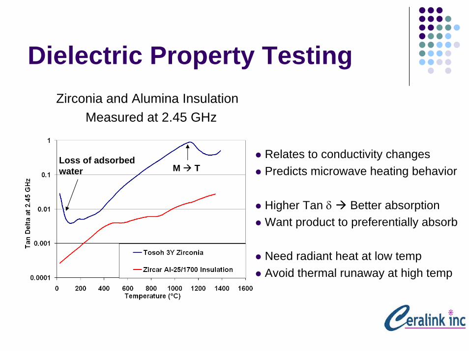
Dielectric Property TestingZirconia and Alumina Insulation
Measured at 2.45 GHz
Relates to conductivity changes Predicts microwave heating behavior
Higher Tan δ Better absorptionWant product to preferentially absorb
Need radiant heat at low tempAvoid thermal runaway at high temp
M TLoss of adsorbedwater

Ceramic Processing: Dielectric Properties Change
Kaolin Clay Permittivity *
** Kaolin Metakaolin
† Metakaolin Mullite
* Drying
***
†
* R. Hutcheon, Microwave Properties North
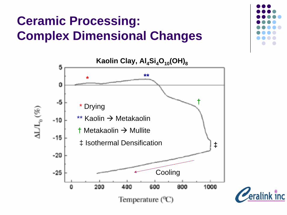
Ceramic Processing:Complex Dimensional Changes
Kaolin Clay, Al4Si4O10(OH)8
** Kaolin Metakaolin
† Metakaolin Mullite
‡ Isothermal Densification
* Drying
Cooling
* **
‡
†
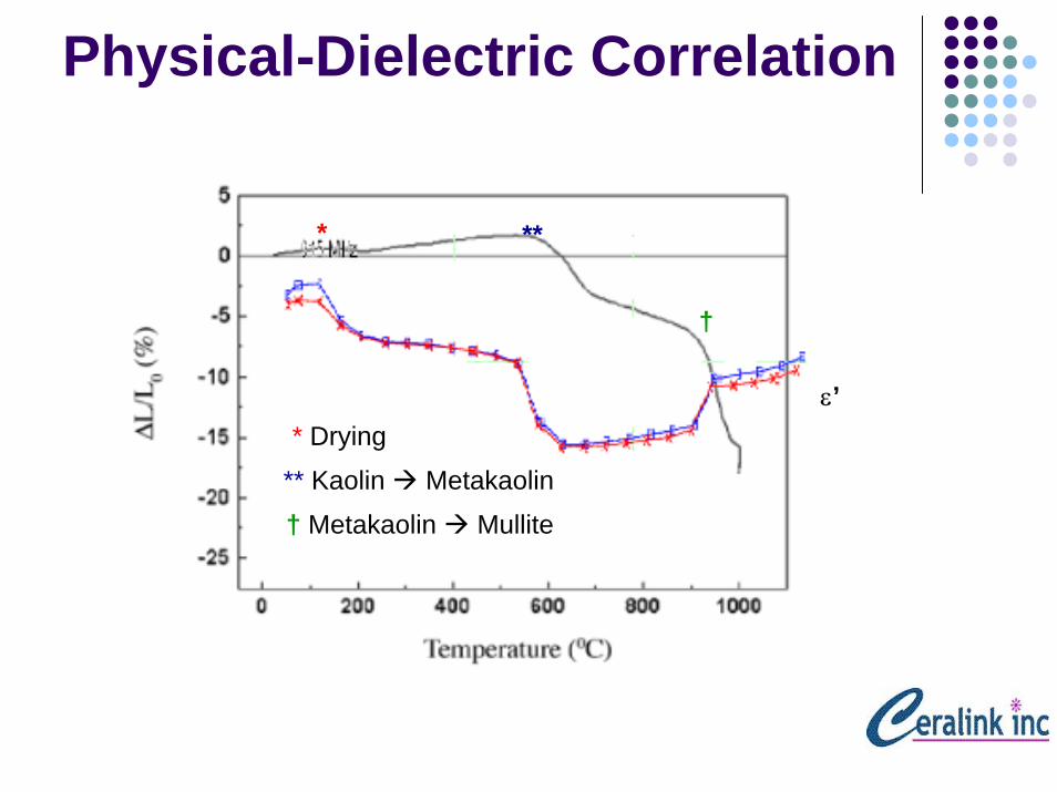
Physical-Dielectric Correlation
** Kaolin Metakaolin
† Metakaolin Mullite
* Drying
* **
†
ε’
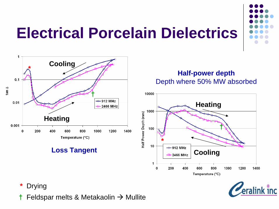
Electrical Porcelain Dielectrics
Half-power depthDepth where 50% MW absorbed
Loss Tangent
Heating
Heating
Cooling
Cooling
*
†
*
†
* Drying† Feldspar melts & Metakaolin Mullite
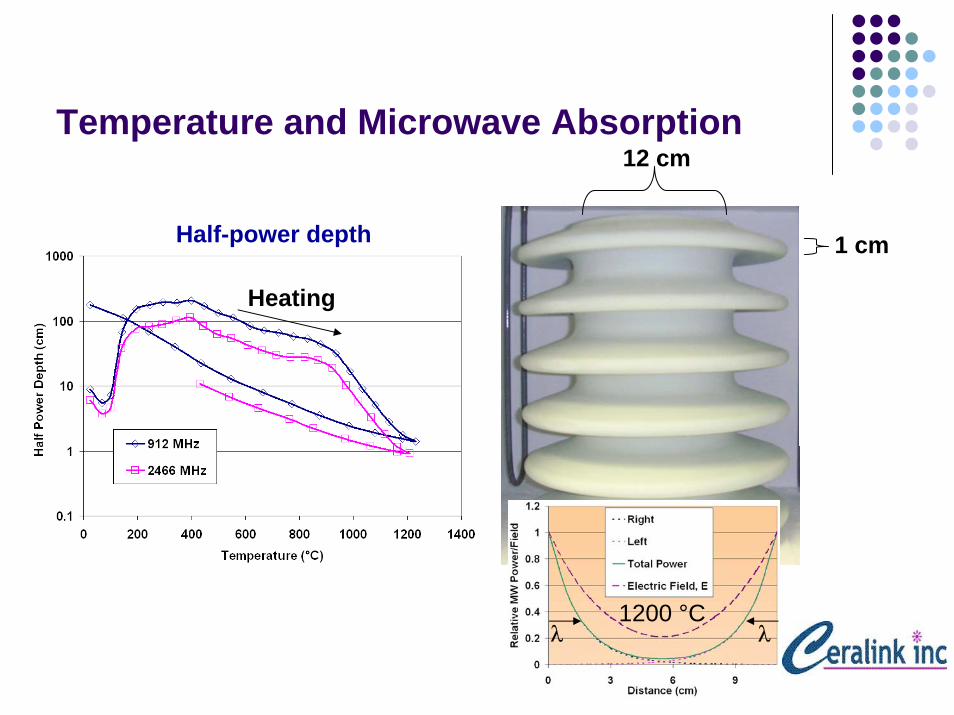
Temperature and Microwave Absorption
Half-power depth
12 cm
1 cm
Heating
λ λ1200 °C
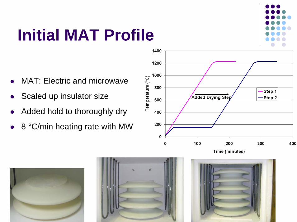
Initial MAT Profile
MAT: Electric and microwave
Scaled up insulator size
Added hold to thoroughly dry
8 °C/min heating rate with MW
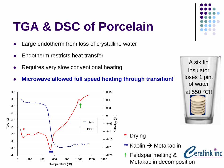
TGA & DSC of PorcelainLarge endotherm from loss of crystalline water
Endotherm restricts heat transfer
Requires very slow conventional heating
Microwave allowed full speed heating through transition!
A six fininsulator
loses 1 pint of water
at 550 °C!!
*
†
**
* Drying
** Kaolin Metakaolin
† Feldspar melting &Metakaolin decomposition
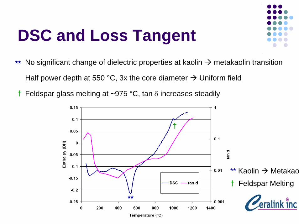
DSC and Loss TangentNo significant change of dielectric properties at kaolin metakaolin transition
Half power depth at 550 °C, 3x the core diameter Uniform field
Feldspar glass melting at ~975 °C, tan δ increases steadily
† Feldspar Melting
** Kaolin Metakao
†
**
†
**
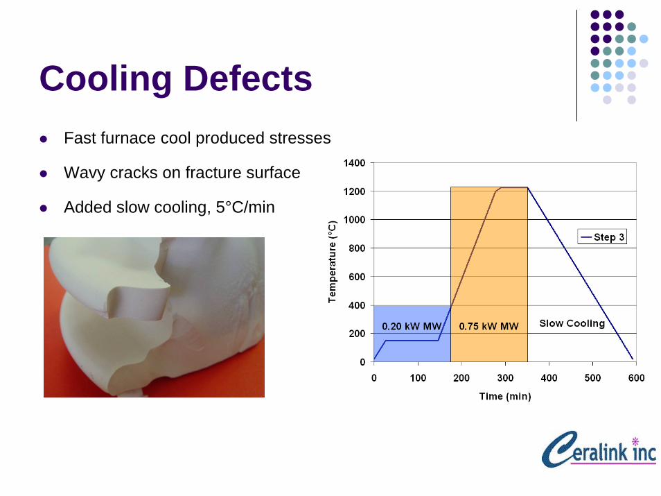
Cooling DefectsFast furnace cool produced stresses
Wavy cracks on fracture surface
Added slow cooling, 5°C/min
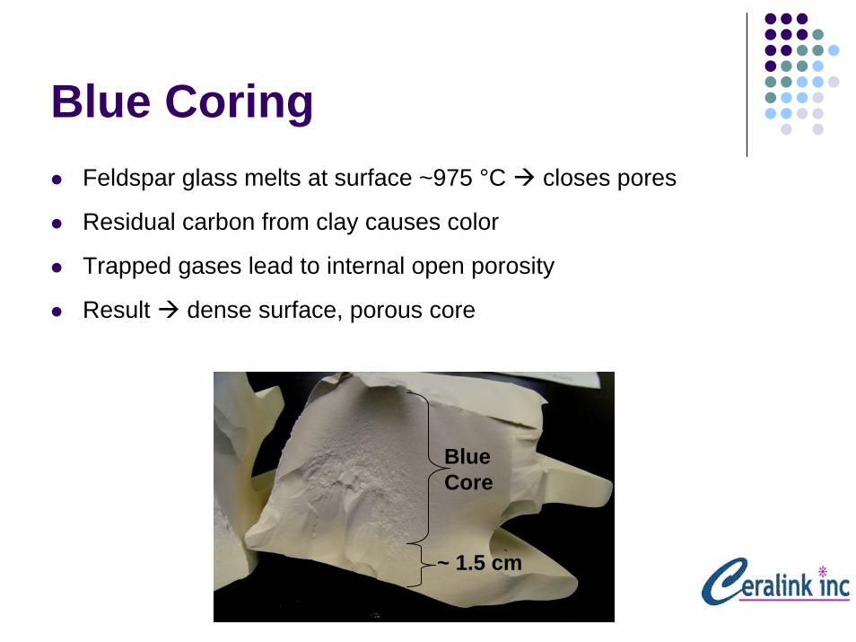
Blue CoringFeldspar glass melts at surface ~975 °C closes pores
Residual carbon from clay causes color
Trapped gases lead to internal open porosity
Result dense surface, porous core
BlueCore
~ 1.5 cm
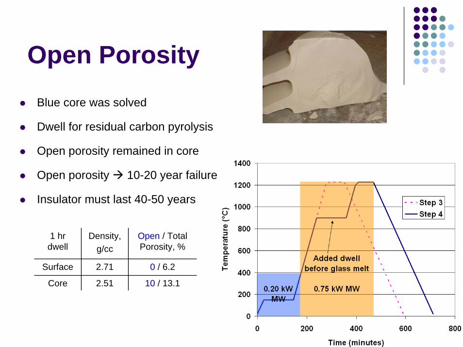
Open PorosityBlue core was solved
Dwell for residual carbon pyrolysis
Open porosity remained in core
Open porosity 10-20 year failure
Insulator must last 40-50 years
1 hr dwell
Density,g/cc
Open / Total Porosity, %
Surface 2.71 0 / 6.2
Core 2.51 10 / 13.1
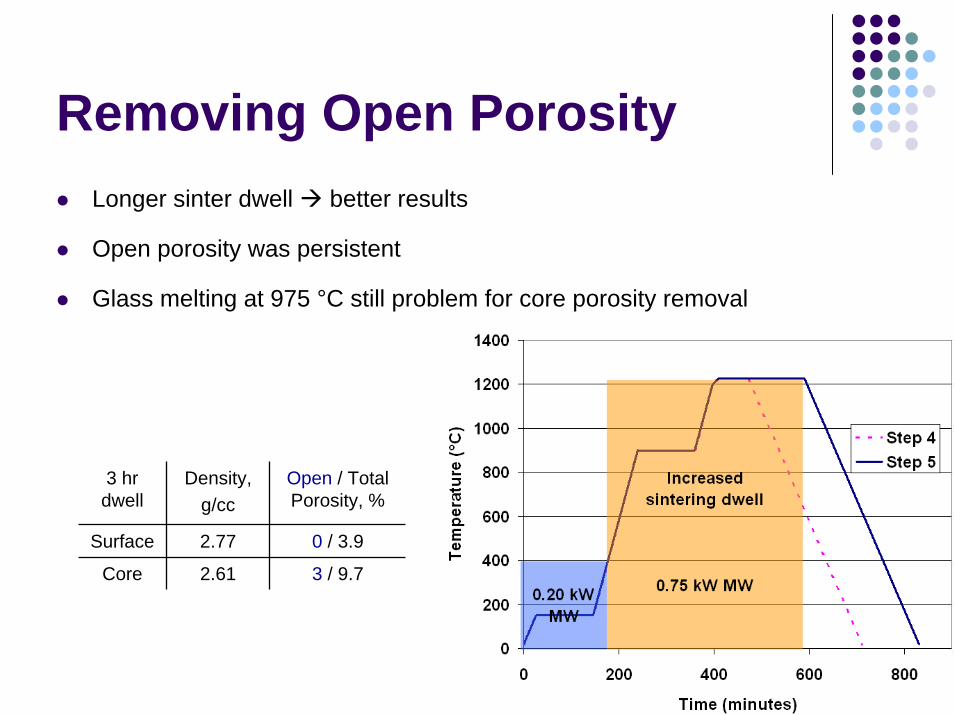
Removing Open PorosityLonger sinter dwell better results
Open porosity was persistent
Glass melting at 975 °C still problem for core porosity removal
3 hr dwell
Density,g/cc
Open / Total Porosity, %
Surface 2.77 0 / 3.9
Core 2.61 3 / 9.7
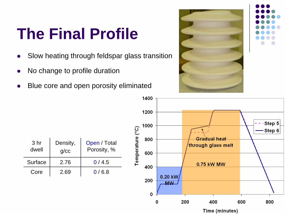
The Final ProfileSlow heating through feldspar glass transition
No change to profile duration
Blue core and open porosity eliminated
3 hr dwell
Density,g/cc
Open / Total Porosity, %
Surface 2.76 0 / 4.5
Core 2.69 0 / 6.8
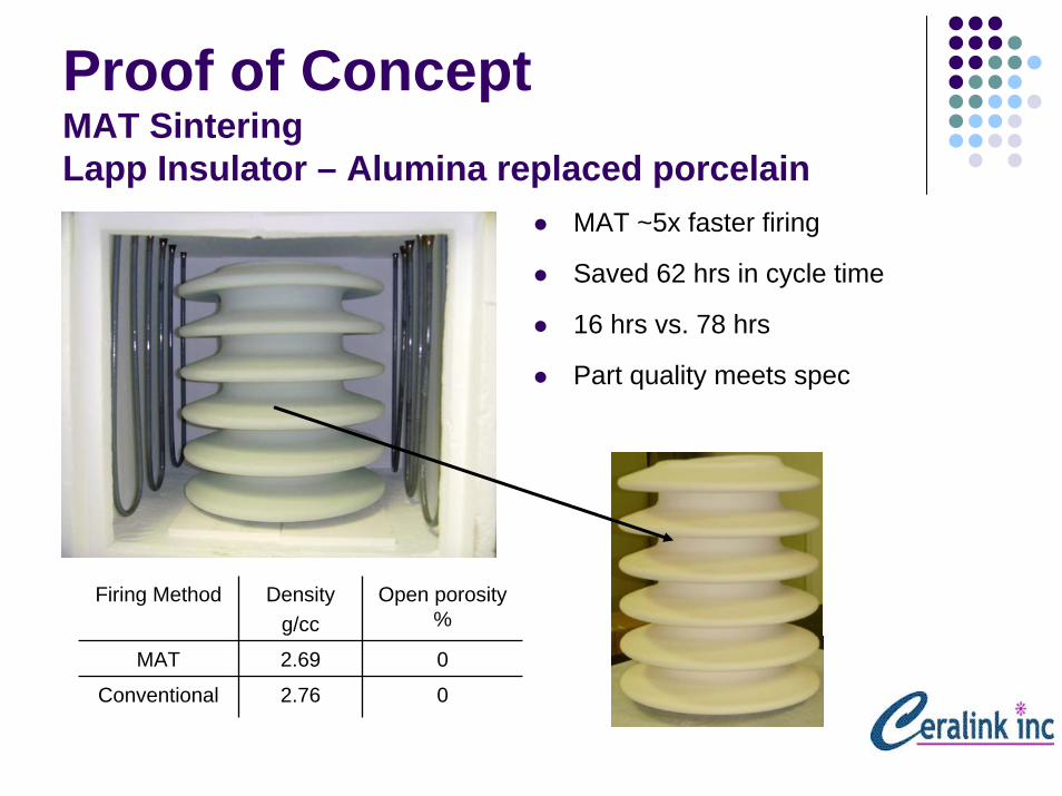
Proof of ConceptMAT SinteringLapp Insulator – Alumina replaced porcelain
MAT ~5x faster firing
Saved 62 hrs in cycle time
16 hrs vs. 78 hrs
Part quality meets spec
Firing Method Densityg/cc
Open porosity %
MAT
Conventional
2.69 0
2.76 0
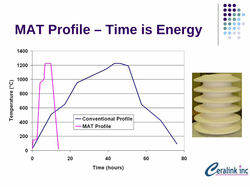
MAT Profile – Time is Energy
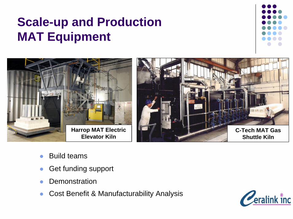
Scale-up and Production MAT Equipment
C-Tech MAT Gas Shuttle Kiln
Harrop MAT Electric Elevator Kiln
Build teams
Get funding support
Demonstration
Cost Benefit & Manufacturability Analysis
SummaryMicrowave heating (MAT) allowed fast firing of insulators
Large cross-section benefitted despite low microwave penetration
Dielectric properties, DSC and TGA all critical to process
Lapp’s expertise with process facilitated rapid development
MAT resulted in nearly 5x shorter firing cycle
Acknowledgments
Dr. Ron HutcheonMicrowave Properties North