Embed Size (px)
DESCRIPTION
Commissioning Status of the LCLS Accelerator and Undulator Systems. Henrik Loos for the LCLS Commissioning Team. Overview. LCLS Introduction Accelerator Commissioning Emittance Laser Heater Bunch Compression Feedback Stability Undulator Commissioning Diagnostics Beam Based Alignment - PowerPoint PPT Presentation
Citation preview
1 Henrik [email protected]
1LCLS Commissioning StatusPulse Seminar 4/3/2009
Commissioning Status of the LCLS Accelerator and Undulator Systems
Henrik Loos
for the LCLS Commissioning Team
2 Henrik [email protected]
2LCLS Commissioning StatusPulse Seminar 4/3/2009
Overview
LCLS IntroductionAccelerator Commissioning
EmittanceLaser HeaterBunch CompressionFeedbackStability
Undulator CommissioningDiagnosticsBeam Based AlignmentSpontaneous Radiation
Outlook
3 Henrik [email protected]
3LCLS Commissioning StatusPulse Seminar 4/3/2009
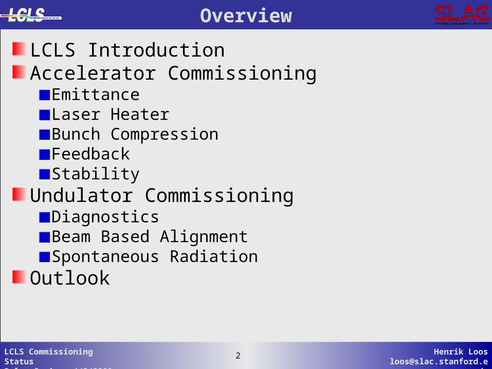
Linac Coherent Light Source at Linac Coherent Light Source at SLACSLAC
Injector (35Injector (35ºº))at 2-km pointat 2-km point
Existing 1/3 Linac (1 km)Existing 1/3 Linac (1 km)(with modifications)(with modifications)
Near Experiment HallNear Experiment Hall
Far ExperimentFar ExperimentHallHall
Undulator (130 m)Undulator (130 m)
X-FEL based on last 1-km of existing linacX-FEL based on last 1-km of existing linacX-FEL based on last 1-km of existing linacX-FEL based on last 1-km of existing linac
New New ee Transfer Line (340 m) Transfer Line (340 m)
1.5-15 Å1.5-15 Å1.5-15 Å1.5-15 Å
X-ray X-ray Transport Transport Line (200 m)Line (200 m)
4 Henrik [email protected]
4LCLS Commissioning StatusPulse Seminar 4/3/2009
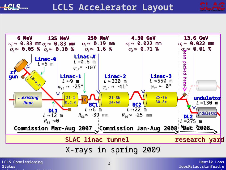
X-rays in spring 2009X-rays in spring 2009SLAC linac tunnelSLAC linac tunnel research yardresearch yard
Linac-0Linac-0L L =6 m=6 m
Linac-1Linac-1L L 9 m9 m
rf rf 25°25°
Linac-2Linac-2L L 330 m330 mrf rf 41°41°
Linac-3Linac-3L L 550 m550 mrf rf 0° 0°
BC1BC1L L 6 m6 m
RR5656 39 mm39 mm
BC2BC2L L 22 m22 m
RR5656 25 mm25 mm DL2 DL2 L L =275 m=275 mRR56 56 0 0
DL1DL1L L 12 m12 mRR56 56 0 0
undulatorundulatorL L =130 m=130 m
6 MeV6 MeVz z 0.83 mm 0.83 mm 0.05 %0.05 %
135 MeV135 MeVz z 0.83 mm 0.83 mm 0.10 %0.10 %
250 MeV250 MeVz z 0.19 mm 0.19 mm 1.6 %1.6 %
4.30 GeV4.30 GeVz z 0.022 mm 0.022 mm 0.71 %0.71 %
13.6 GeV13.6 GeVz z 0.022 mm 0.022 mm 0.01 %0.01 %
Linac-Linac-XXL L =0.6 m=0.6 mrfrf= =
21-1b,c,d
...existinglinac
L0-a,b
rfrfgungun
21-3b24-6dX
25-1a30-8c
undulatorundulator
Commission Mar-Aug 2007Commission Mar-Aug 2007 Commission Jan-Aug 2008Commission Jan-Aug 2008 Dec 2008…Dec 2008…
be
am
pa
rked
he
reb
ea
m p
arke
d h
ere
LCLS Accelerator Layout
5 Henrik [email protected]
5LCLS Commissioning StatusPulse Seminar 4/3/2009
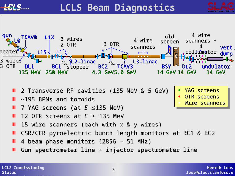
LCLS Beam Diagnostics
BC2BC24.3 GeV4.3 GeV
BSYBSY14 GeV14 GeV
TCAV3TCAV35.0 GeV5.0 GeV
BC1BC1250 MeV250 MeV
L1SL1S
3 wires3 wires2 OTR2 OTR
L1XL1X4 wire4 wire
scannersscanners
L2-linacL2-linac L3-linacL3-linacDL1DL1
135 MeV135 MeV
L0L0gungun TCAV0TCAV0 oldold
screenscreen3 OTR3 OTR
zz11 zz223 wires3 wires3 OTR3 OTR stopperstopper
heaterheater
w
all
wal
l
DL2DL214 GeV14 GeV
undulatorundulator14 GeV14 GeV
4 wire4 wirescanners +scanners +
4 collimators4 collimators vert.vert.dumpdump
2 Transverse RF cavities (135 MeV & 5 GeV)2 Transverse RF cavities (135 MeV & 5 GeV)
~195 BPMs and toroids~195 BPMs and toroids
7 YAG screens (at 7 YAG screens (at EE 135 MeV)135 MeV)
12 OTR screens at 12 OTR screens at EE 135 MeV 135 MeV
15 wire scanners (each with x & y wires)15 wire scanners (each with x & y wires)
CSR/CER pyroelectric bunch length monitors at BC1 & BC2CSR/CER pyroelectric bunch length monitors at BC1 & BC2
4 beam phase monitors (2856 – 51 MHz)4 beam phase monitors (2856 – 51 MHz)
Gun spectrometer line + injector spectrometer lineGun spectrometer line + injector spectrometer line
• YAG screensYAG screens• OTR screensOTR screens• Wire scannersWire scanners
• YAG screensYAG screens• OTR screensOTR screens• Wire scannersWire scanners
6 Henrik [email protected]
6LCLS Commissioning StatusPulse Seminar 4/3/2009
Injector Emittance Commissioning
-8 -7 -6 -50
50
100
150
Bea
m S
ize
( m
)
-1 -0.5 0 0.5 1
-1
-0.5
0
0.5
1
Nor
m. A
ngle
-8 -7 -6 -50
50
100
150
QUAD:IN20:525:BDES (kG)
Bea
m S
ize
( m
)
-1 -0.5 0 0.5 1
-1
-0.5
0
0.5
1
Norm. Position
Nor
m. A
ngle
-8 -7 -6 -50
50
100
150
Bea
m S
ize
( m
)
-1 -0.5 0 0.5 1
-1
-0.5
0
0.5
1
Nor
m. A
ngle
-8 -7 -6 -50
50
100
150
QUAD:IN20:525:BDES (kG)
Bea
m S
ize
( m
)
-1 -0.5 0 0.5 1
-1
-0.5
0
0.5
1
Norm. Position
Nor
m. A
ngle
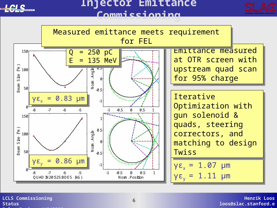
Q = 250 pCE = 135 MeV
Q = 250 pCE = 135 MeV
γεy = 0.86 μmγεy = 0.86 μm
γεx = 0.83 μmγεx = 0.83 μm
Emittance measured at OTR screen with upstream quad scanfor 95% charge
Emittance measured at OTR screen with upstream quad scanfor 95% charge
For 1 nCγεx= 1.07 μmγεy= 1.11 μm
For 1 nCγεx= 1.07 μmγεy= 1.11 μm
Iterative Optimization with gun solenoid & quads, steering correctors, and matching to design Twiss
Iterative Optimization with gun solenoid & quads, steering correctors, and matching to design Twiss
Measured emittance meets requirement for FELMeasured emittance meets requirement for FEL
7 Henrik [email protected]
7LCLS Commissioning StatusPulse Seminar 4/3/2009
New LTU Wire-Scanners Working Well
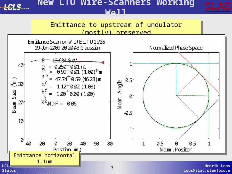
Emittance to upstream of undulator (mostly) preservedEmittance to upstream of undulator (mostly) preserved
-40 -20 0 20 40 60 800
10
20
30
40
Position (m)
Bea
m S
ize
(m
)
Emittance Scan on WIRE:LTU1:735 19-Jan-2009 20:20:43 Gaussian
E = 13.634 GeVQ = 0.250 0.01 nC
y = 0.99 0.01 ( 1.00) m
y = 47.74 0.59 (46.23) m
y = 1.12 0.02 ( 1.08)
y = 1.00 0.00 ( 1.00)
2/NDF = 0.06
-1 -0.5 0 0.5 1
-1
-0.5
0
0.5
1
Norm. Position
Nor
m. A
ngle
Normalized Phase Space
Emittance horizontal 1.1umEmittance horizontal 1.1um
8 Henrik [email protected]
8LCLS Commissioning StatusPulse Seminar 4/3/2009
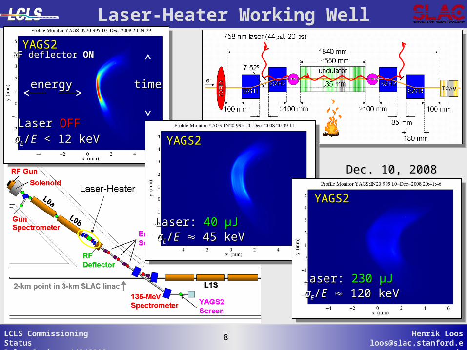
YAGS2YAGS2
Laser Laser OFFOFFσσEE//EE < 12 keV < 12 keV
RF deflector RF deflector ONON
timetimeenergyenergy
Dec. 10, 2008Dec. 10, 2008
Laser-Heater Working Well
YAGS2YAGS2
Laser: Laser: 40 40 µµJJσσEE//EE 45 keV 45 keV
YAGS2YAGS2
Laser: Laser: 230 230 µµJJσσEE//EE 120 keV 120 keV
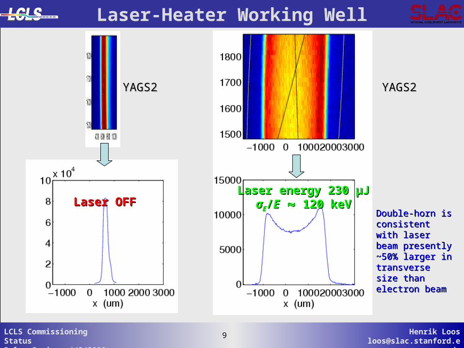
9 Henrik [email protected]
9LCLS Commissioning StatusPulse Seminar 4/3/2009
Double-horn is Double-horn is consistent with consistent with laser beam laser beam presently ~50% presently ~50% larger in larger in transverse size transverse size than electron than electron beambeam
Laser energy 230 Laser energy 230 µµJJσσEE//EE 120 keV 120 keV
YAGS2YAGS2 YAGS2YAGS2
Laser OFFLaser OFF
Laser-Heater Working Well
10 Henrik [email protected]
10LCLS Commissioning StatusPulse Seminar 4/3/2009
-35 -30 -25 -20 -15 -10 -5 00
20
40
60
80
100
120
BC2 R56 (mm)
s ( m
)
MeasuredElegant
-35 -30 -25 -20 -15 -10 -5 00
20
40
60
80
100
120
BC2 R56 (mm)
s ( m
)
MeasuredElegant
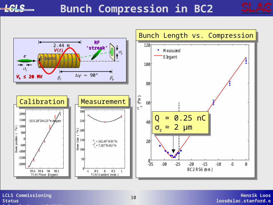
Bunch Compression in BC2
Q = 0.25 nCσz ≈ 2 μm
Q = 0.25 nCσz ≈ 2 μm
89.6 89.8 90 90.2
-2000
-1500
-1000
-500
0
500
1000
1500
2000
TCAV Phase (Degree)
Bea
m p
ositi
on (
m)
5515.20244.23 m/degree
89.6 89.8 90 90.2
-2000
-1500
-1000
-500
0
500
1000
1500
2000
TCAV Phase (Degree)
Bea
m p
ositi
on (
m)
5515.20244.23 m/degree
-1 -0.5 0 0.5 10
50
100
150
200
250
300
TCAV Gradient (norm.)
Bea
m S
ize
( m
)
y = 242.49 0.95 m
z = 7.2870.452 m
-1 -0.5 0 0.5 10
50
100
150
200
250
300
TCAV Gradient (norm.)
Bea
m S
ize
( m
)
y = 242.49 0.95 m
z = 7.2870.452 m
CalibrationCalibration MeasurementMeasurement
VV00 ≤≤ 20 MV 20 MV
ee
zz
2.44 m2.44 m
cc pp 90°90°
VV((tt)) yy
RFRF‘‘streak’streak’
SS-band-band
Bunch Length vs. CompressionBunch Length vs. Compression
11 Henrik [email protected]
11LCLS Commissioning StatusPulse Seminar 4/3/2009
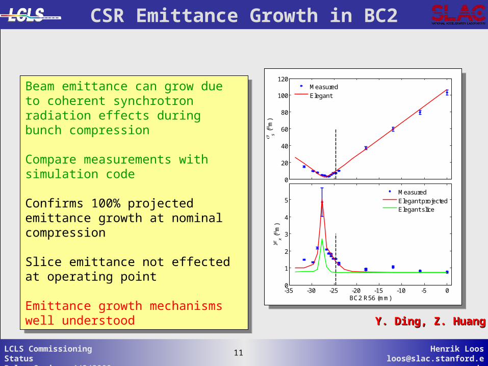
CSR Emittance Growth in BC2
Beam emittance can grow due to coherent synchrotron radiation effects during bunch compression
Compare measurements with simulation code
Confirms 100% projected emittance growth at nominal compression
Slice emittance not effected at operating point
Emittance growth mechanisms well understood
Beam emittance can grow due to coherent synchrotron radiation effects during bunch compression
Compare measurements with simulation code
Confirms 100% projected emittance growth at nominal compression
Slice emittance not effected at operating point
Emittance growth mechanisms well understood -35 -30 -25 -20 -15 -10 -5 0
0
1
2
3
4
5
BC2 R56 (mm)
x (
m)
MeasuredElegant projectedElegant slice
0
20
40
60
80
100
120
s ( m
)
MeasuredElegant
-35 -30 -25 -20 -15 -10 -5 00
1
2
3
4
5
BC2 R56 (mm)
x (
m)
MeasuredElegant projectedElegant slice
0
20
40
60
80
100
120
s ( m
)
MeasuredElegant
Y. Ding, Z. HuangY. Ding, Z. Huang
12 Henrik [email protected]
12LCLS Commissioning StatusPulse Seminar 4/3/2009
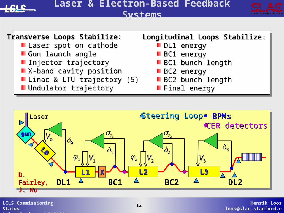
Longitudinal Loops Stabilize:Longitudinal Loops Stabilize:DL1 energyDL1 energyBC1 energyBC1 energyBC1 bunch lengthBC1 bunch lengthBC2 energyBC2 energyBC2 bunch lengthBC2 bunch lengthFinal energyFinal energy
Transverse Loops Stabilize:Transverse Loops Stabilize:Laser spot on cathodeLaser spot on cathodeGun launch angleGun launch angleInjector trajectoryInjector trajectoryX-band cavity positionX-band cavity positionLinac & LTU trajectory (5)Linac & LTU trajectory (5)Undulator trajectoryUndulator trajectory
Laser & Electron-Based Feedback Systems
L0L0
gungun
L3L3L2L2XX
DL1 BC1 DL2L1L1
zz11
1111 VV11
zz22
2222 VV22
33
VV33
00VV00
D. Fairley,D. Fairley,J. WuJ. Wu BC2
BPMsBPMsCER detectorsCER detectors
Steering LoopSteering LoopLaserLaser
13 Henrik [email protected]
13LCLS Commissioning StatusPulse Seminar 4/3/2009
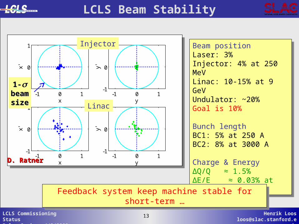
LCLS Beam Stability
-1 0 1-1
0
1
x
x'
-1 0 1-1
0
1
yy'
-1 0 1-1
0
1
x
x'
-1 0 1-1
0
1
y
y'-1 0 1
-1
0
1
x
x'
-1 0 1-1
0
1
yy'
-1 0 1-1
0
1
x
x'
-1 0 1-1
0
1
y
y'
Linac
InjectorBeam positionLaser: 3%Injector: 4% at 250 MeVLinac: 10-15% at 9 GeVUndulator: ~20%Goal is 10%
Bunch lengthBC1: 5% at 250 ABC2: 8% at 3000 A
Charge & EnergyΔQ/Q ≈ 1.5%ΔE/E ≈ 0.03% at 13.6 GeV
Beam positionLaser: 3%Injector: 4% at 250 MeVLinac: 10-15% at 9 GeVUndulator: ~20%Goal is 10%
Bunch lengthBC1: 5% at 250 ABC2: 8% at 3000 A
Charge & EnergyΔQ/Q ≈ 1.5%ΔE/E ≈ 0.03% at 13.6 GeV
1-1- beam beam sizesize
D. RatnerD. Ratner
Feedback system keep machine stable for short-term …Feedback system keep machine stable for short-term …
14 Henrik [email protected]
14LCLS Commissioning StatusPulse Seminar 4/3/2009
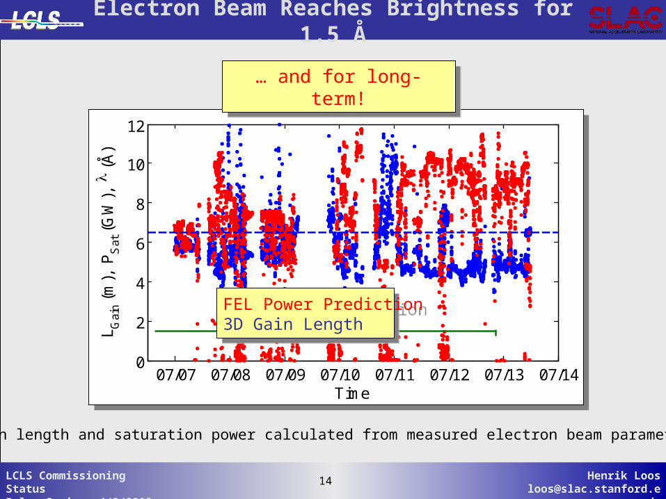
Electron Beam Reaches Brightness for 1.5 Å
Gain length and saturation power calculated from measured electron beam parameters
07/07 07/08 07/09 07/10 07/11 07/12 07/13 07/140
2
4
6
8
10
12
Time
L Gai
n (m
), P
Sat
(G
W),
(
Å)
07/07 07/08 07/09 07/10 07/11 07/12 07/13 07/140
2
4
6
8
10
12
Time
L Gai
n (m
), P
Sat
(G
W),
(
Å)
FEL Power Prediction3D Gain Length
FEL Power Prediction3D Gain Length
… and for long-term!… and for long-term!
15 Henrik [email protected]
15LCLS Commissioning StatusPulse Seminar 4/3/2009
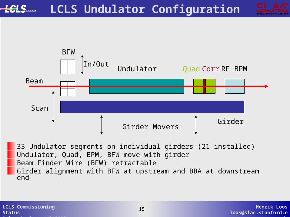
LCLS Undulator Configuration
33 Undulator segments on individual girders (21 installed)Undulator, Quad, BPM, BFW move with girderBeam Finder Wire (BFW) retractableGirder alignment with BFW at upstream and BBA at downstream end
In/Out
Scan
Beam
Undulator Quad RF BPM
Girder
BFW
Corr
Girder Movers
16 Henrik [email protected]
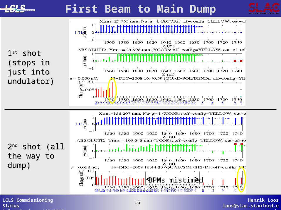
16LCLS Commissioning StatusPulse Seminar 4/3/2009
22ndnd shot (all the shot (all the way to dump)way to dump)
11stst shot (stops in shot (stops in just into undulator)just into undulator)
BPMs mistimedBPMs mistimed
First Beam to Main Dump
17 Henrik [email protected]
17LCLS Commissioning StatusPulse Seminar 4/3/2009
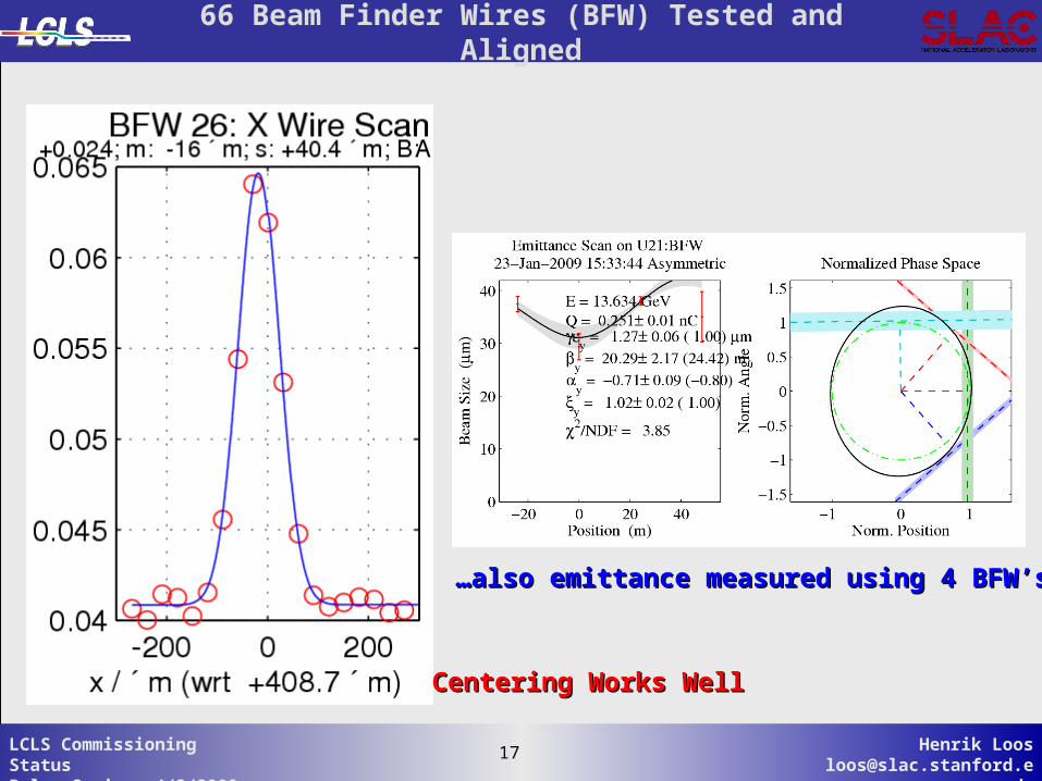
……also emittance measured using 4 BFW’salso emittance measured using 4 BFW’s
Centering Works WellCentering Works Well
66 Beam Finder Wires (BFW) Tested and Aligned
18 Henrik [email protected]
18LCLS Commissioning StatusPulse Seminar 4/3/2009
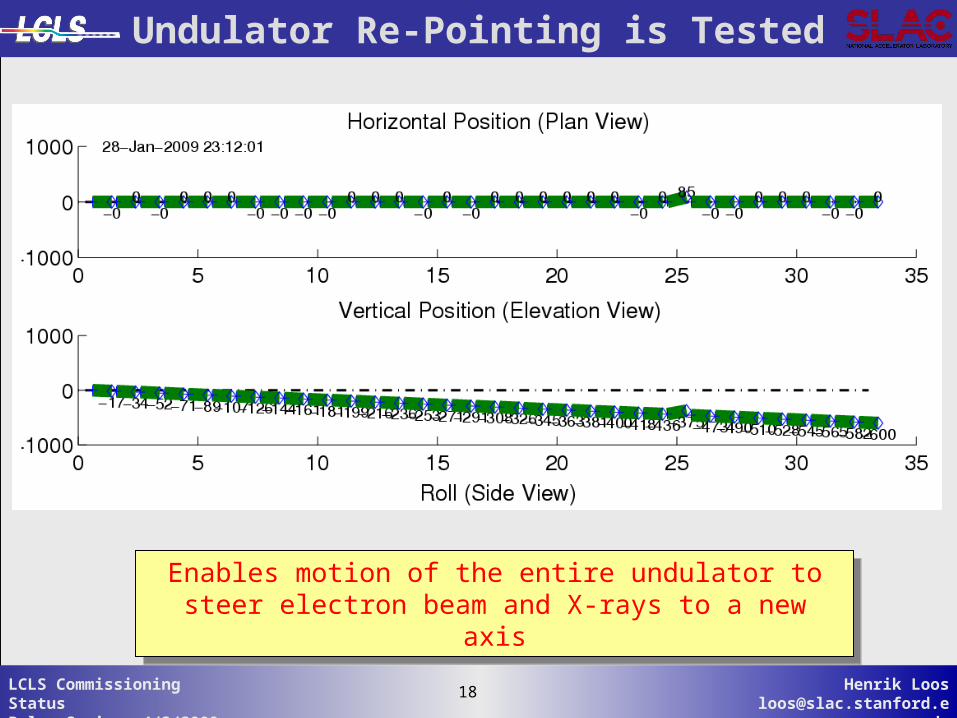
Undulator Re-Pointing is Tested
Enables motion of the entire undulator to steer electron beam and X-rays to a new axis
Enables motion of the entire undulator to steer electron beam and X-rays to a new axis
19 Henrik [email protected]
19LCLS Commissioning StatusPulse Seminar 4/3/2009
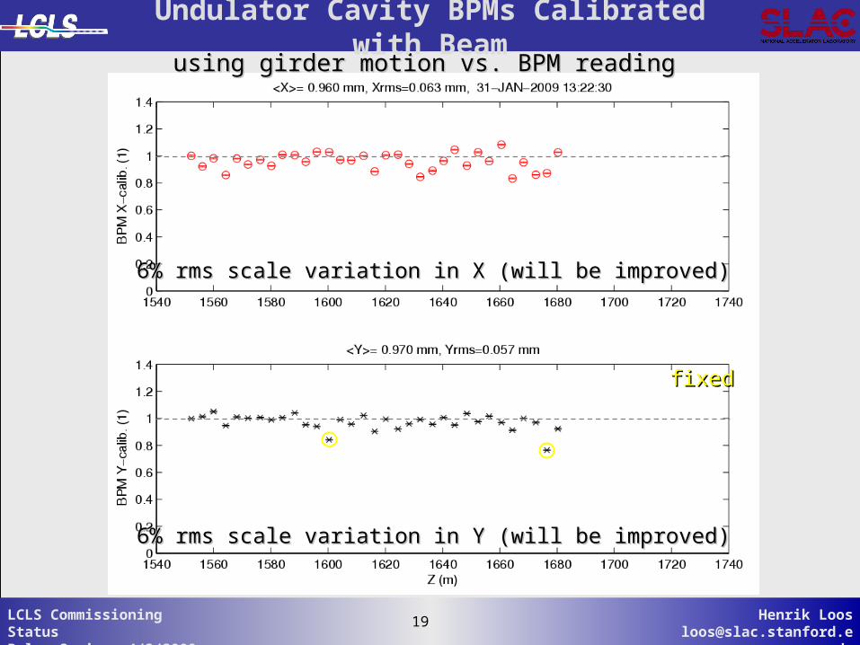
using girder motion vs. BPM readingusing girder motion vs. BPM reading
6% rms scale variation in X (will be improved)6% rms scale variation in X (will be improved)
6% rms scale variation in Y (will be improved)6% rms scale variation in Y (will be improved)
fixedfixed
Undulator Cavity BPMs Calibrated with Beam
20 Henrik [email protected]
20LCLS Commissioning StatusPulse Seminar 4/3/2009
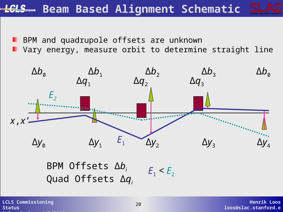
Beam Based Alignment Schematic
Δq1 Δq3Δq2
Δb1 Δb3Δb2
Δy1 Δy3Δy2Δy0 Δy4
Δb0Δb0
E1
E2
BPM Offsets Δbi
Quad Offsets Δqi
x,x’
E1 < E2
BPM and quadrupole offsets are unknownVary energy, measure orbit to determine straight line
21 Henrik [email protected]
21LCLS Commissioning StatusPulse Seminar 4/3/2009
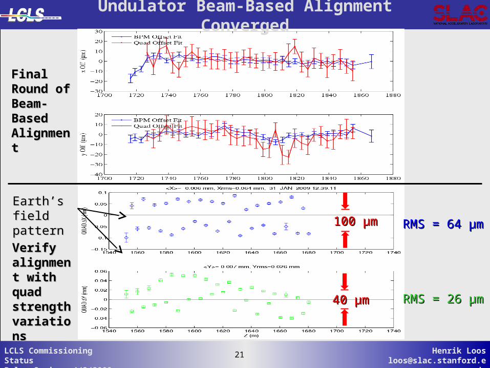
Final Final Round of Round of Beam-Beam-Based Based AlignmentAlignment
40 40 µµmm
100 100 µµmm RMS = 64 RMS = 64 µµmm
RMS = 26 RMS = 26 µµmm
Earth’s field Earth’s field patternpattern
Verify Verify alignment alignment with quad with quad strength strength variationsvariations
Undulator Beam-Based Alignment Converged
22 Henrik [email protected]
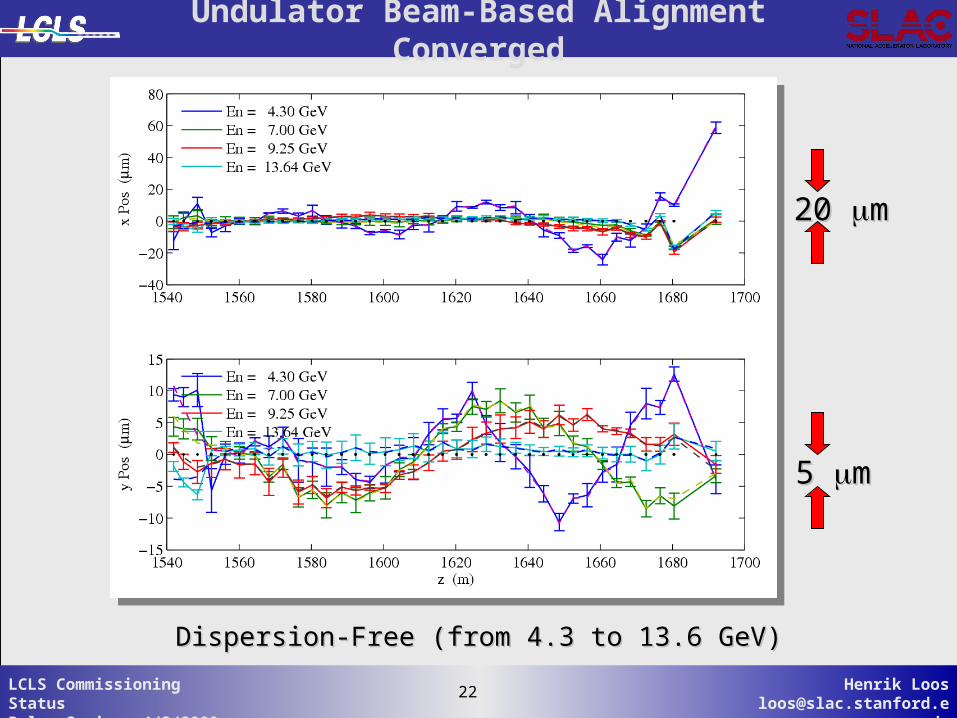
22LCLS Commissioning StatusPulse Seminar 4/3/2009
Dispersion-Free (from 4.3 to 13.6 GeV)Dispersion-Free (from 4.3 to 13.6 GeV)
Undulator Beam-Based Alignment Converged
20 20 mm
5 5 mm
23 Henrik [email protected]
23LCLS Commissioning StatusPulse Seminar 4/3/2009
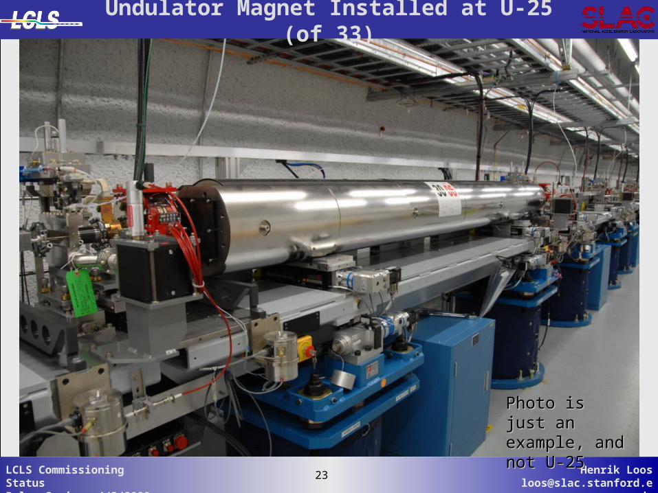
Photo is just an Photo is just an example, and example, and not U-25not U-25
Undulator Magnet Installed at U-25 (of 33)
24 Henrik [email protected]
24LCLS Commissioning StatusPulse Seminar 4/3/2009
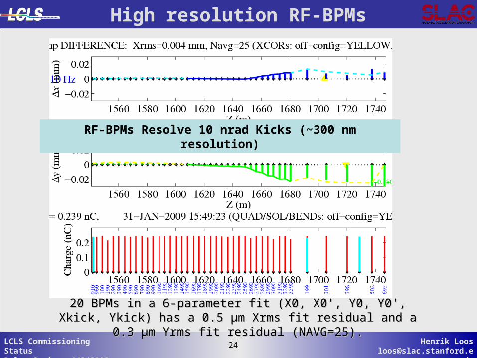
20 BPMs in a 6-parameter fit (X0, X0', Y0, Y0', Xkick, Ykick) has a 0.5 20 BPMs in a 6-parameter fit (X0, X0', Y0, Y0', Xkick, Ykick) has a 0.5 µµm Xrms fit residual and a 0.3 µm Yrms fit residual (NAVG=25).m Xrms fit residual and a 0.3 µm Yrms fit residual (NAVG=25).
High resolution RF-BPMs
RF-BPMs Resolve 10 nrad Kicks (~300 nm resolution)
25 Henrik [email protected]
25LCLS Commissioning StatusPulse Seminar 4/3/2009
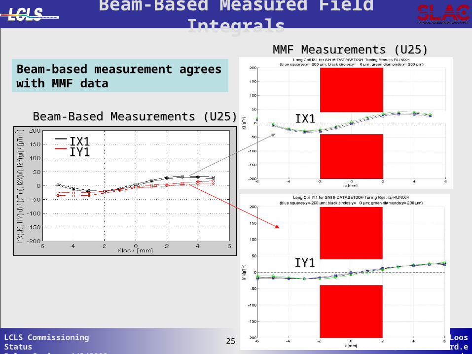
Beam-Based Measurements (U25)Beam-Based Measurements (U25)
MMF Measurements (U25)MMF Measurements (U25)
IX1IX1IY1IY1
IX1IX1
IY1IY1
Beam-Based Measured Field Integrals
Beam-based measurement agrees with MMF data
26 Henrik [email protected]
26LCLS Commissioning StatusPulse Seminar 4/3/2009
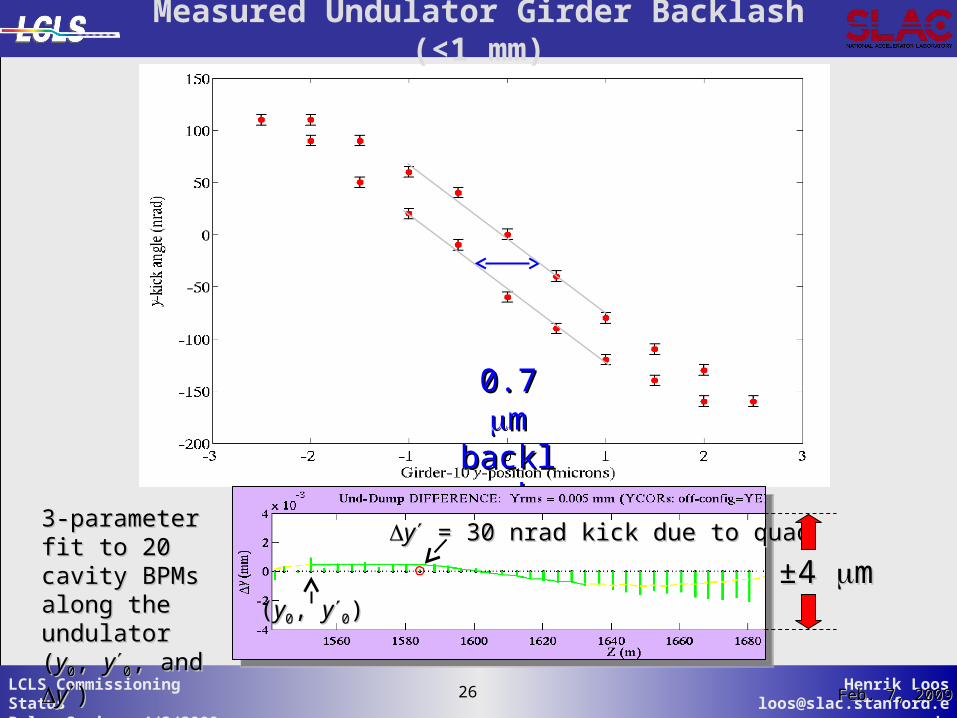
0.7 0.7 mmbacklasbacklas
hh
yy = 30 nrad kick due to quad = 30 nrad kick due to quad
±±4 4 mm
3-parameter fit 3-parameter fit to 20 cavity to 20 cavity BPMs along the BPMs along the undulator (undulator (yy00, ,
yy00, and , and yy))
Feb. 7, 2009Feb. 7, 2009
((yy00, , yy00))
Measured Undulator Girder Backlash (<1 mm)
27 Henrik [email protected]
27LCLS Commissioning StatusPulse Seminar 4/3/2009
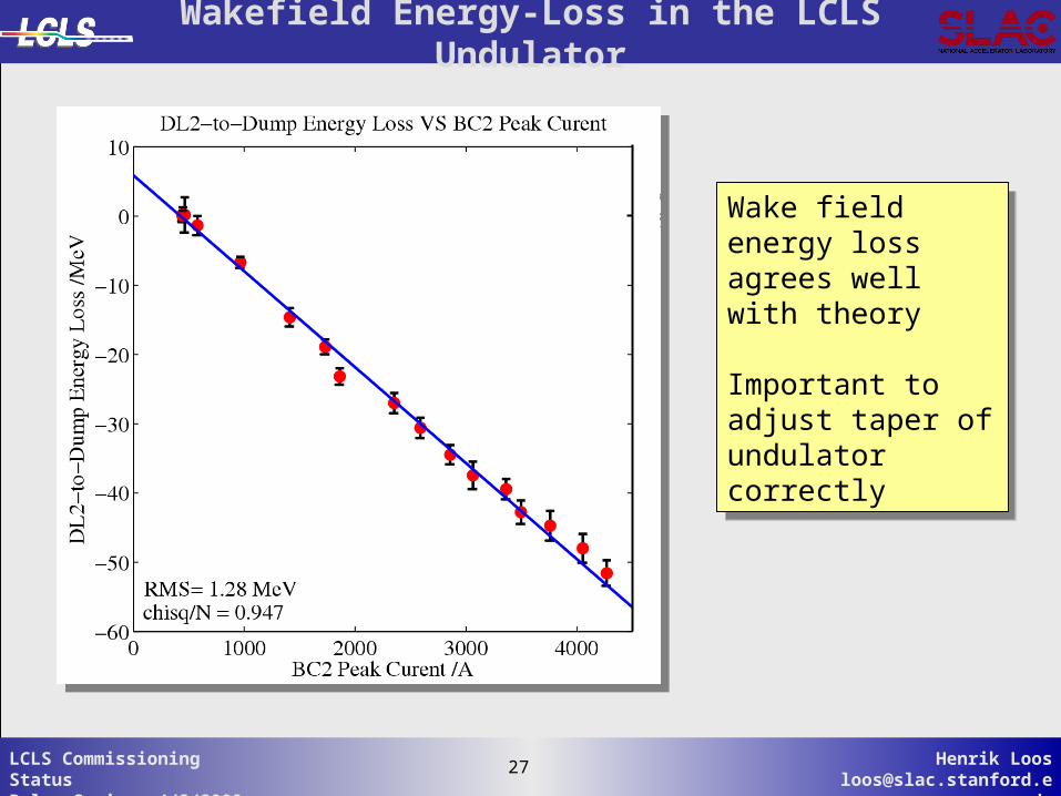
Wakefield Energy-Loss in the LCLS Undulator
Wake field energy loss agrees well with theory
Important to adjust taper of undulator correctly
Wake field energy loss agrees well with theory
Important to adjust taper of undulator correctly
28 Henrik [email protected]
28LCLS Commissioning StatusPulse Seminar 4/3/2009
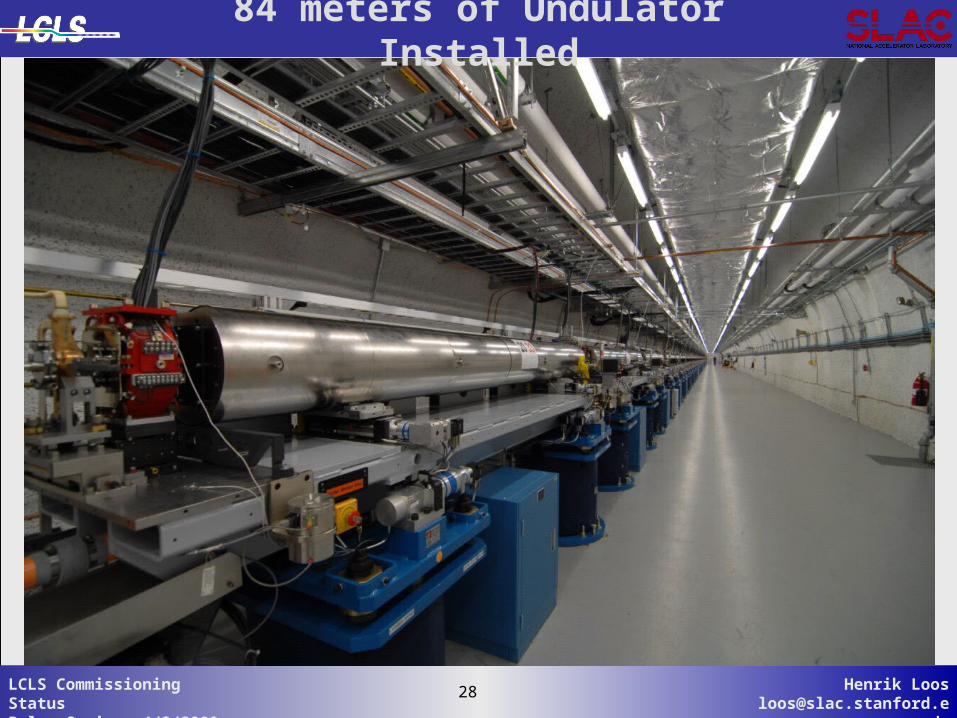
84 meters of Undulator Installed
29 Henrik [email protected]
29LCLS Commissioning StatusPulse Seminar 4/3/2009
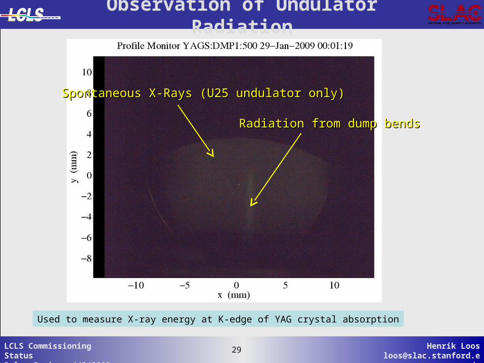
Observation of Undulator Radiation
Spontaneous X-Rays (U25 undulator only)Spontaneous X-Rays (U25 undulator only)
Radiation from dump bendsRadiation from dump bends
Used to measure X-ray energy at K-edge of YAG crystal absorption
30 Henrik [email protected]
30LCLS Commissioning StatusPulse Seminar 4/3/2009
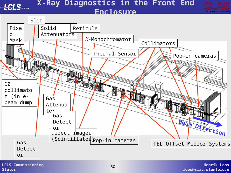
Gas Detector
Gas Attenuator
Direct Imager(Scintillator)
FEL Offset Mirror Systems
Beam Direction
SolidAttenuators
K-Monochromator
Thermal Sensor
Slit
Collimators
Pop-in cameras
Pop-in cameras
Reticule
C0 collimator (in e- beam dump
Fixed Mask
GasDetector
X-Ray Diagnostics in the Front End Enclosure
31 Henrik [email protected]
31LCLS Commissioning StatusPulse Seminar 4/3/2009
Summary
Accelerator commissioned mostly to design goalsAccelerator commissioned mostly to design goals
Laser heater commissioned and working well (does not salvage OTR Laser heater commissioned and working well (does not salvage OTR screen quantitative use – many MPS problems)screen quantitative use – many MPS problems)
Beam-based alignment converged to required level (should improve Beam-based alignment converged to required level (should improve after undulators installed due to after undulators installed due to µµ-shielding of Earth’s field)-shielding of Earth’s field)
New LTU wire scanners working routinelyNew LTU wire scanners working routinely
Cavity BPMs commissioned and working fantasticallyCavity BPMs commissioned and working fantastically
One undulator field integrals confirmed with beamOne undulator field integrals confirmed with beam
21 undulators installed21 undulators installed
Full motion control on all girders (+ 21 undulators) working wellFull motion control on all girders (+ 21 undulators) working well
All beam finder wires (BFW) checked out and aligned with beamAll beam finder wires (BFW) checked out and aligned with beam
BFW’s also used successfully to measure emittanceBFW’s also used successfully to measure emittance
Full 6x6 feedback running (some over-sensitivity to machine setup Full 6x6 feedback running (some over-sensitivity to machine setup still)still)
Soon hopefully to observe first FEL lightSoon hopefully to observe first FEL light
32 Henrik [email protected]
32LCLS Commissioning StatusPulse Seminar 4/3/2009
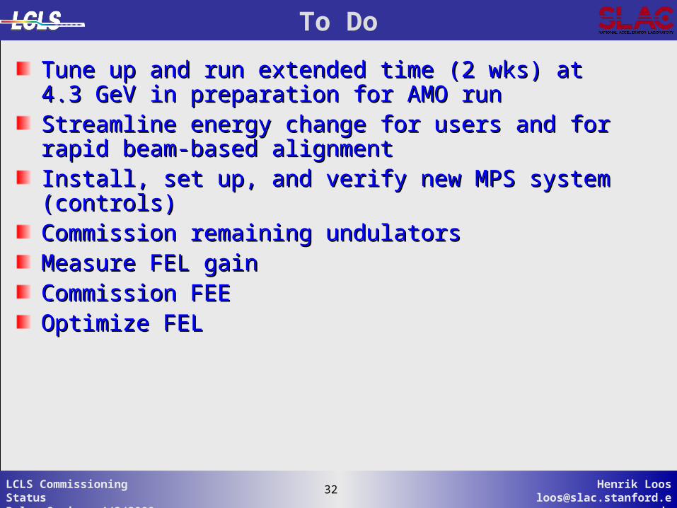
Tune up and run extended time (2 wks) at 4.3 GeV in Tune up and run extended time (2 wks) at 4.3 GeV in preparation for AMO runpreparation for AMO runStreamline energy change for users and for rapid beam-Streamline energy change for users and for rapid beam-based alignmentbased alignmentInstall, set up, and verify new MPS system (controls)Install, set up, and verify new MPS system (controls)Commission remaining undulatorsCommission remaining undulatorsMeasure FEL gainMeasure FEL gainCommission FEECommission FEEOptimize FELOptimize FEL
To Do
33 Henrik [email protected]
33LCLS Commissioning StatusPulse Seminar 4/3/2009
Re-establishRe-establishee to SL2 to SL2
LTU/LTU/UndUnd
Comm. Comm.
Firs
t Li
ght
in
Firs
t Li
ght
in
FEE
FEE
Firs
t Li
ght
in F
EH
Firs
t Li
ght
in F
EH
NEH Ops & NEH Ops & CommissioningCommissioning
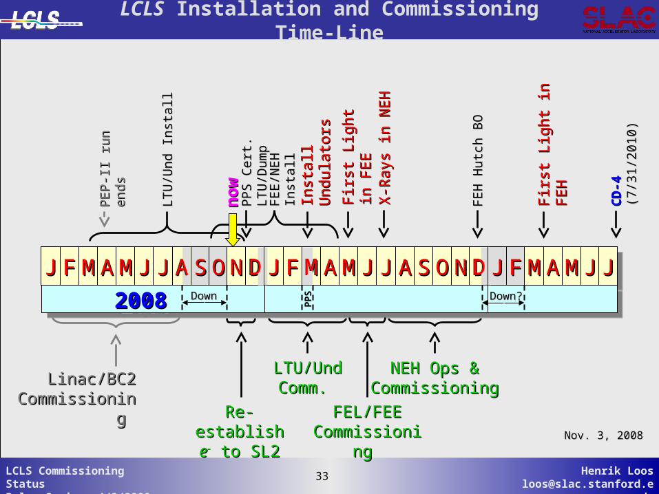
JJJJ FFFF MMMM AAAA MMMM JJJJ JJJJ AAAA SSSS DDDD JJJJ FFFF MMMM AAAA MMMM JJJJ JJJJ AAAA SSSS OOOO NNNN DDDD JJJJ FFFF MMMM AAAA MMMM JJJJ JJJJOONNAA
2008 2009 20102008 2009 2010 2008 2009 20102008 2009 2010DownDownPPS
PPS
Linac/BC2 Linac/BC2 CommissioninCommissionin
g g FEL/FEEFEL/FEECommissioniCommissioni
ng ng Nov. 3, 2008Nov. 3, 2008
Inst
all
Inst
all U
ndula
tors
Undula
tors
MMDD
LTU
/Und
In
stall
LTU
/Und
In
stall
PEP-I
I ru
n
PEP-I
I ru
n
ends
ends
FEE/N
EH
In
stall
FEE/N
EH
In
stall
PPS C
ert
. LT
U/D
um
pPPS C
ert
. LT
U/D
um
p
CD-4
CD-4
(7
/31
/201
0)
(7/3
1/2
01
0)
X-R
ays
in N
EH
X-R
ays
in N
EH
no
wn
ow
DDDown?Down?
FEH
Hutc
h B
OFE
H H
utc
h B
O
LCLS Installation and Commissioning Time-Line
34 Henrik [email protected]
34LCLS Commissioning StatusPulse Seminar 4/3/2009
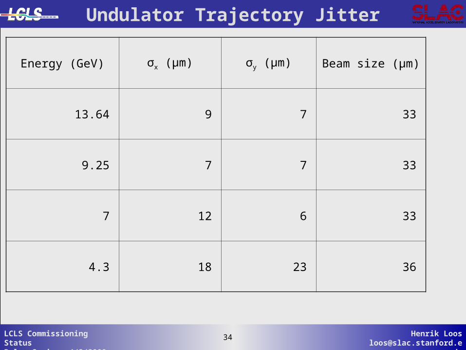
Undulator Trajectory Jitter
Energy (GeV) σx (μm) σy (μm) Beam size (μm)
13.64 9 7 33
9.25 7 7 33
7 12 6 33
4.3 18 23 36