Embed Size (px)
Citation preview
Rules and Tools for Alternative Fuels
1
Combustion Rules and Tools
for Alternative Fuels
Highlights of Phase 1 and R&D Needs
Med Colket
United Technologies Research Center
September 20th, 2010
MACCCR 3rd Annual Fuels Summit
Princeton, NJ
CLEARED for Public Release: Combustion Rules and Tools for Alternative Fuels Originator Reference Number: 88ABW-2010-4974
Rules and Tools for Alternative Fuels
2
Outline
Introduction
Program Objectives and Status
Program Overview
Observed fuel effects
Brief Description of Rigs
Modeling Review
Fundamental R&D Needs
In 8/2009, AFRL and DESC funded the 5 GT engine OEMs
to collaboratively develop a plan to understand fuel effects
on combustor performance and to facilitate fuel certification
processes.
This presentation summarizes the outcome of that program
Rules and Tools for Alternative Fuels
Co-Authors GE Aviation:
John Aicholtz, Thomas Holland, Gurhan Andac, Randall Boehm, Stanford Seto,
and Randy Lewis
Honeywell International, Inc:
Randy Williams, Dan Ludwig, Sunil James, Matt Mosbacher, and Greg Freeman
Liberty Works - Rolls Royce North American Technologies, Inc:
Nader Rizk, Brad Wall, Albert Verdouw, Loren Crook, and Dave Turner
Pratt and Whitney:
Anuj Bhargava, Jeffery Lovett, Randy Mckinney, Steve Kramer, and Med Colket
(UTRC)
Williams International:
Jamey Condevaux, John Sordyl, Andy Mazurkiewicz, and Lisa Simpkins
3
Rules and Tools for Alternative Fuels
4
Introduction (1) USAF needs to reduce its dependency on foreign oil sources
AF Policy Memo 10-2…50% of AF domestic aviation fuel requirement by 2016 via an alternative fuel blend…alternative component derived from domestic sources
Fuel needs to be from renewable or green energy sources (Waxman and Davis) The domestic sourced fuel must show equal to or less lifecycle GHG
than conventional fuels produced from petroleum
Desire speedier/more efficient fuel approval process
Understand impact of new fuels on engine performance and operability
Cost effective screening of alternative fuels (in terms of time, fuel quantities, engine tests)
Commercial aviation faces the same pressures and opportunities
Understand the impact of fuel properties on combustion and engine
performance critical for widespread use of alternative fuels in aviation
Rules and Tools for Alternative Fuels
5
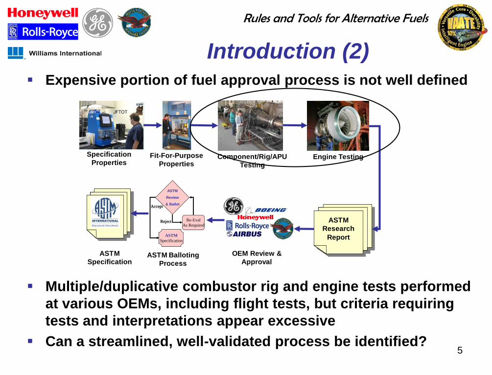
Introduction (2)
Expensive portion of fuel approval process is not well defined
Multiple/duplicative combustor rig and engine tests performed
at various OEMs, including flight tests, but criteria requiring
tests and interpretations appear excessive
Can a streamlined, well-validated process be identified?
OEM Review &
ApprovalASTM Balloting
Process
Specification
PropertiesEngine TestingFit-For-Purpose
PropertiesComponent/Rig/APU
Testing
ASTM
Research
ReportASTM
Specification
Accept
ASTM
Review
& Ballot
Re-Eval
As RequiredReject
ASTM
Specification
Accept
ASTM
Review
& Ballot
Re-Eval
As RequiredReject
ASTM
Specification
Rules and Tools for Alternative Fuels
6
Rules and Tools Program Goals and Plan
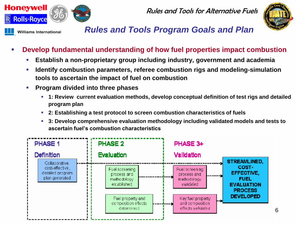
Develop fundamental understanding of how fuel properties impact combustion
Establish a non-proprietary group including industry, government and academia
Identify combustion parameters, referee combustion rigs and modeling-simulation
tools to ascertain the impact of fuel on combustion
Program divided into three phases
1: Review current evaluation methods, develop conceptual definition of test rigs and detailed
program plan
2: Establishing a test protocol to screen combustion characteristics of fuels
3: Develop comprehensive evaluation methodology including validated models and tests to
ascertain fuel’s combustion characteristics
Rules and Tools for Alternative Fuels
7
Phase 1 - Program Accomplishments
Established an integrated working arrangement between all five OEM’s
Created reference databases
Recent OEM fuels testing
Who’s who in fuels
Test sites and capabilities
Reviewed current fuel evaluation process to identify deficiencies & needs
Developed a methodology/process for fuel evaluation
Identified and prioritized Combustion Figures of Merit (FOM’s)
Defined a set of non-proprietary ‘referee’ combustion test articles
Identified and categorized test fuels to benchmark perfomance in the test articles
Identified near term modeling tools to support the proposed methodology
Identified fundamental research needs for longer-term computational modeling and
combustion testing for model validation
Developed a multiphase program approach to mature the methodology and
provided a first-level of detail of the requirements and program plan for the next
phase of the program
Rules and Tools for Alternative Fuels
8
Proposed Phase 2 Program
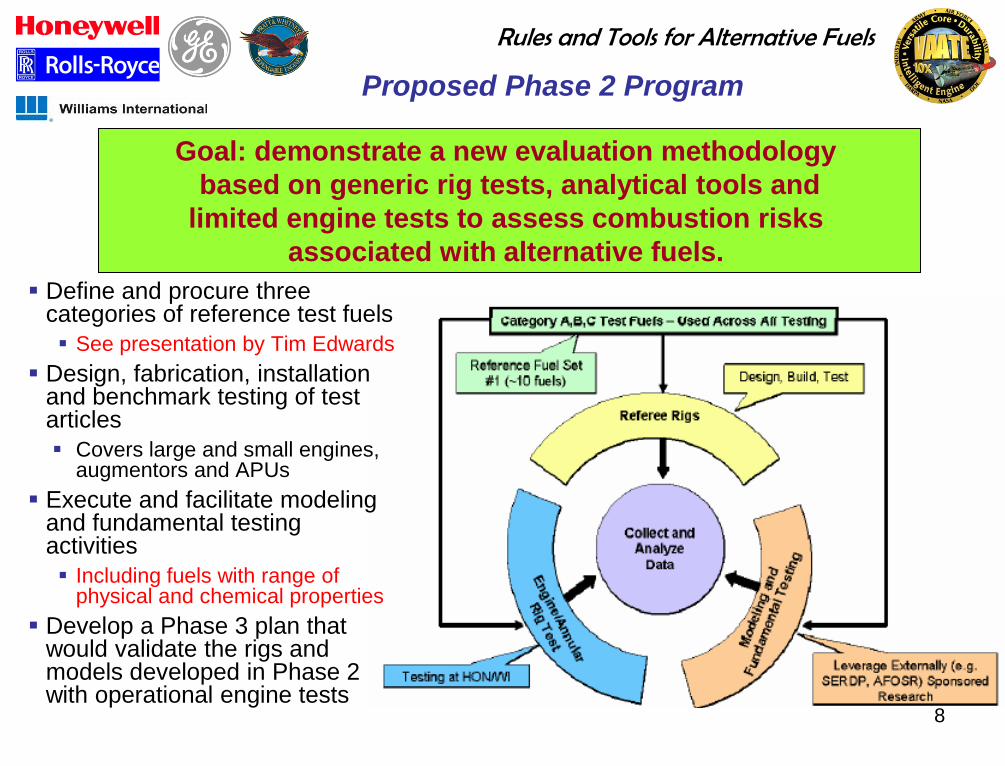
Define and procure three categories of reference test fuels
See presentation by Tim Edwards
Design, fabrication, installation and benchmark testing of test articles
Covers large and small engines, augmentors and APUs
Execute and facilitate modeling and fundamental testing activities
Including fuels with range of physical and chemical properties
Develop a Phase 3 plan that would validate the rigs and models developed in Phase 2 with operational engine tests
Goal: demonstrate a new evaluation methodology
based on generic rig tests, analytical tools and
limited engine tests to assess combustion risks
associated with alternative fuels.
Rules and Tools for Alternative Fuels
9
Phase 2 Proposal
(White Paper)
Design and fabrication of referee rigs
Facility preparation and installation of
rigs/engines
Fuel selection and property tests
Rig/Engine testing
Fundamental combustion tests
Modeling activities
Rules and Tools for Alternative Fuels
10
Current Alternative Fuels Environment
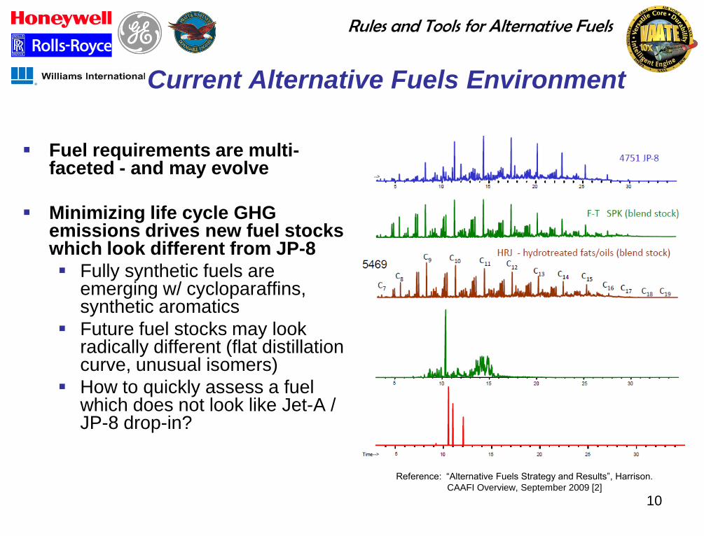
Fuel requirements are multi-faceted - and may evolve
Minimizing life cycle GHG emissions drives new fuel stocks which look different from JP-8
Fully synthetic fuels are emerging w/ cycloparaffins, synthetic aromatics
Future fuel stocks may look radically different (flat distillation curve, unusual isomers)
How to quickly assess a fuel which does not look like Jet-A / JP-8 drop-in?
Reference: “Alternative Fuels Strategy and Results”, Harrison.
CAAFI Overview, September 2009 [2]
Rules and Tools for Alternative Fuels
11
Observations from Alternative Fuel
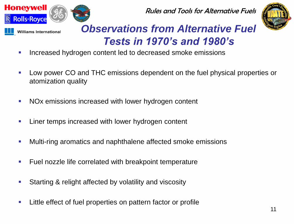
Tests in 1970’s and 1980’s Increased hydrogen content led to decreased smoke emissions
Low power CO and THC emissions dependent on the fuel physical properties or
atomization quality
NOx emissions increased with lower hydrogen content
Liner temps increased with lower hydrogen content
Multi-ring aromatics and naphthalene affected smoke emissions
Fuel nozzle life correlated with breakpoint temperature
Starting & relight affected by volatility and viscosity
Little effect of fuel properties on pattern factor or profile
Rules and Tools for Alternative Fuels
12
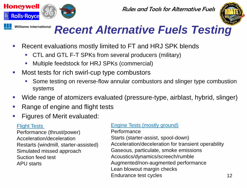
Recent Alternative Fuels Testing
Recent evaluations mostly limited to FT and HRJ SPK blends
CTL and GTL F-T SPKs from several producers (military)
Multiple feedstock for HRJ SPKs (commercial)
Most tests for rich swirl-cup type combustors
Some testing on reverse-flow annular combustors and slinger type combustion
systems
Wide range of atomizers evaluated (pressure-type, airblast, hybrid, slinger)
Range of engine and flight tests
Figures of Merit evaluated:
Engine Tests (mostly ground)
Performance
Starts (starter-assist, spool-down)
Acceleration/deceleration for transient operability
Gaseous, particulate, smoke emissions
Acoustics/dynamics/screech/rumble
Augmented/non-augmented performance
Lean blowout margin checks
Endurance test cycles
Flight Tests
Performance (thrust/power)
Acceleration/deceleration
Restarts (windmill, starter-assisted)
Simulated missed approach
Suction feed test
APU starts
Rules and Tools for Alternative Fuels
13
Indications from Recent
Alternative Fuel Tests
Mixed impact on ignition and lean blowout (LBO) characteristics
Inconclusive impact on gaseous emissions
Significant reduction in smoke emissions (lower aromatics)
No impact on combustor exit temperatures
Effect on durability not evaluated
Rules and Tools for Alternative Fuels
14
Specific Trends Observed
FT and Bio-SPK/HRJ fuels showed no significant impact on
ignition and LBO within operational range
Bio-Jet showed overall positive impact on ignition and LBO
JP-900 and DCL fuels and FAME blends (both with high
density and viscosity) had mixed impact DCL fuel showed a positive impact on ignition and LBO, contrary to expectations
based on physical properties (high viscosity, low volatility), may be due to chemical
composition (cyclo-paraffins)
FAME fuel blends (down to 20% FAME) showed significant negative impact in ignition
and LBO during both component and system level testing
Bio-SPK1 (high relative viscosity) showed an overall
negative impact on LBO
Some FT SPK blends had low density
Rules and Tools for Alternative Fuels
15
Combustion Characteristics
Consensus opinion of OEMs:
• Key properties: the most critical (operationally) and the most likely phenomena to be
affected by fuel property variation.
• Lean Blow Out (LBO)
• Ignition and relight
• Other properties to monitor: either are of secondary importance or have little impact on
safety/operation
• e.g., emissions, etc.
Rules and Tools for Alternative Fuels
16
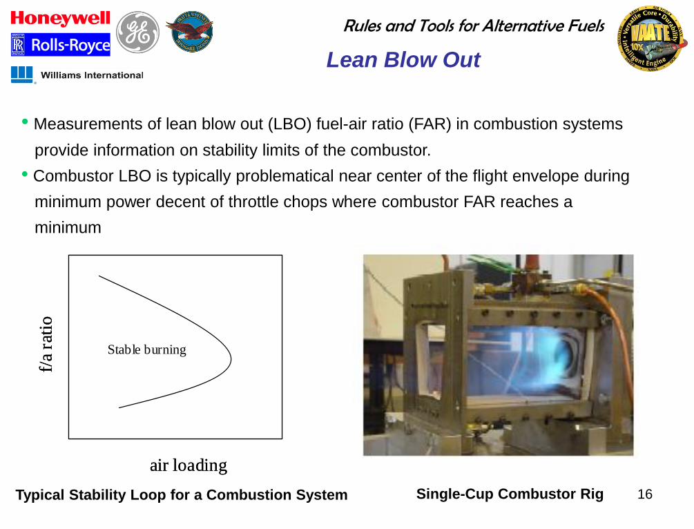
Lean Blow Out
• Measurements of lean blow out (LBO) fuel-air ratio (FAR) in combustion systems
provide information on stability limits of the combustor.
• Combustor LBO is typically problematical near center of the flight envelope during
minimum power decent of throttle chops where combustor FAR reaches a
minimum
Stable burning
f/a
rati
o
air loading
Stable burning
f/a
rati
o
air loading
Typical Stability Loop for a Combustion System Single-Cup Combustor Rig
Rules and Tools for Alternative Fuels
17
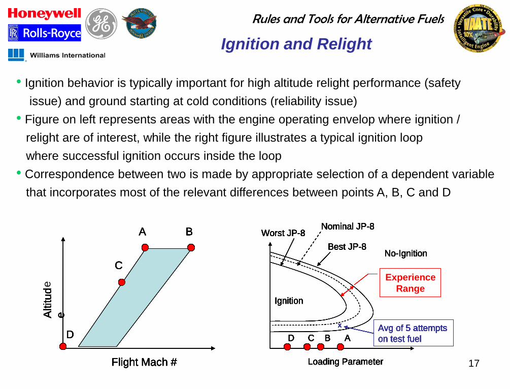
Ignition and Relight
• Ignition behavior is typically important for high altitude relight performance (safety
issue) and ground starting at cold conditions (reliability issue)
• Figure on left represents areas with the engine operating envelop where ignition /
relight are of interest, while the right figure illustrates a typical ignition loop
where successful ignition occurs inside the loop
• Correspondence between two is made by appropriate selection of a dependent variable
that incorporates most of the relevant differences between points A, B, C and D
Flight Mach #
Altitu
d
e
A B
C
D
Loading Parameter
ACD B
Ignition
No-Ignition
X Avg of 5 attempts
on test fuel
Best JP-8
Worst JP-8Nominal JP-8
Acceptance
Range
Loading Parameter
ACD B
Ignition
No-Ignition
X Avg of 5 attempts
on test fuel
Best JP-8
Worst JP-8Nominal JP-8
Acceptance
Range
Condition Pressure Temperature dP/P etc
A 5 -20 5%
B 10 20 4%
C 10 150 4%
D 14.7 250 3%JPTSBest Case JP-8
JP-8 / TBDNominal JP-8
Worst case JP-5Worst Case JP-8
propertypropertypropertyFuel / SourceNotionally identified Fuels:
JPTSBest Case JP-8
JP-8 / TBDNominal JP-8
Worst case JP-5Worst Case JP-8
propertypropertypropertyFuel / SourceNotionally identified Fuels:
Flight Mach #
Altitu
d
e
A B
C
D
Flight Mach #
Altitu
d
e
A B
C
D
Loading Parameter
ACD B
Ignition
No-Ignition
X Avg of 5 attempts
on test fuel
Best JP-8
Worst JP-8Nominal JP-8
Acceptance
Range
Loading Parameter
ACD B
Ignition
No-Ignition
X Avg of 5 attempts
on test fuel
Best JP-8
Worst JP-8Nominal JP-8
Acceptance
Range
Condition Pressure Temperature dP/P etc
A 5 -20 5%
B 10 20 4%
C 10 150 4%
D 14.7 250 3%JPTSBest Case JP-8
JP-8 / TBDNominal JP-8
Worst case JP-5Worst Case JP-8
propertypropertypropertyFuel / SourceNotionally identified Fuels:
JPTSBest Case JP-8
JP-8 / TBDNominal JP-8
Worst case JP-5Worst Case JP-8
propertypropertypropertyFuel / SourceNotionally identified Fuels:
Experience
Range
Flight Mach #
Altitu
d
e
A B
C
D
Loading Parameter
ACD B
Ignition
No-Ignition
X Avg of 5 attempts
on test fuel
Best JP-8
Worst JP-8Nominal JP-8
Acceptance
Range
Loading Parameter
ACD B
Ignition
No-Ignition
X Avg of 5 attempts
on test fuel
Best JP-8
Worst JP-8Nominal JP-8
Acceptance
Range
Condition Pressure Temperature dP/P etc
A 5 -20 5%
B 10 20 4%
C 10 150 4%
D 14.7 250 3%JPTSBest Case JP-8
JP-8 / TBDNominal JP-8
Worst case JP-5Worst Case JP-8
propertypropertypropertyFuel / SourceNotionally identified Fuels:
JPTSBest Case JP-8
JP-8 / TBDNominal JP-8
Worst case JP-5Worst Case JP-8
propertypropertypropertyFuel / SourceNotionally identified Fuels:
Flight Mach #
Altitu
d
e
A B
C
D
Flight Mach #
Altitu
d
e
A B
C
D
Loading Parameter
ACD B
Ignition
No-Ignition
X Avg of 5 attempts
on test fuel
Best JP-8
Worst JP-8Nominal JP-8
Acceptance
Range
Loading Parameter
ACD B
Ignition
No-Ignition
X Avg of 5 attempts
on test fuel
Best JP-8
Worst JP-8Nominal JP-8
Acceptance
Range
Condition Pressure Temperature dP/P etc
A 5 -20 5%
B 10 20 4%
C 10 150 4%
D 14.7 250 3%JPTSBest Case JP-8
JP-8 / TBDNominal JP-8
Worst case JP-5Worst Case JP-8
propertypropertypropertyFuel / SourceNotionally identified Fuels:
JPTSBest Case JP-8
JP-8 / TBDNominal JP-8
Worst case JP-5Worst Case JP-8
propertypropertypropertyFuel / SourceNotionally identified Fuels:
Experience
Range
e
Rules and Tools for Alternative Fuels
18
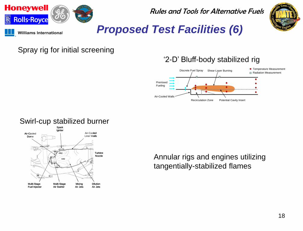
Proposed Test Facilities (6)
Multi-Stage
Fuel Injector
Multi-Stage
Air Swirler
Air-Cooled
Dome
Air-Cooled
Liner Walls
ORZ
CRZ
Spark
Igniter
Mixing
Air Jets
Dilution
Air Jets
Turbine
Nozzle
Multi-Stage
Fuel Injector
Multi-Stage
Air Swirler
Air-Cooled
Dome
Air-Cooled
Liner Walls
ORZ
CRZ
Spark
Igniter
Mixing
Air Jets
Dilution
Air Jets
Turbine
Nozzle
Swirl-cup stabilized burner
Discrete Fuel Spray
Premixed
Fueling
Air-Cooled Walls
Recirculation Zone Potential Cavity Insert
Shear-Layer BurningTemperature Measurement
Radiation Measurement
„2-D‟ Bluff-body stabilized rig
Annular rigs and engines utilizing
tangentially-stabilized flames
Spray rig for initial screening
Rules and Tools for Alternative Fuels
19 19
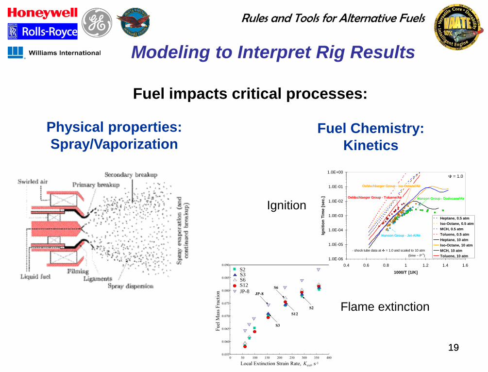
Modeling to Interpret Rig Results
Fuel impacts critical processes:
Fuel Chemistry:
Kinetics
1.0E-06
1.0E-05
1.0E-04
1.0E-03
1.0E-02
1.0E-01
1.0E+00
0.4 0.6 0.8 1 1.2 1.4 1.6
1000/T [1/K]
Ign
itio
n T
ime
[s
ec.]
Heptane, 0.5 atm
Iso-Octane, 0.5 atm
MCH, 0.5 atm
Toluene, 0.5 atm
Heptane, 10 atm
Iso-Octane, 10 atm
MCH, 10 atm
Toluene, 10 atm
= 1.0
Hanson Group - Jet-A/Air
Hanson Group - Dodecane/Air
- shock tube data at = 1.0 and scaled to 10 atm
(time ~ P-1
)
Oehlschlaeger Group - iso-Octane/Air
Oehlschlaeger Group - Toluene/Air
Physical properties:
Spray/Vaporization
4003503002502001501005000.055
0.060
0.065
0.070
0.075
0.080
0.085
0.090
Local Extinction Strain Rate, Kext, s-1
Fuel
Mas
s F
ract
ion JP-8
S6
S2
S3
S12
S2
S12
S3
JP-8
S6
Ignition
Flame extinction
Rules and Tools for Alternative Fuels
20
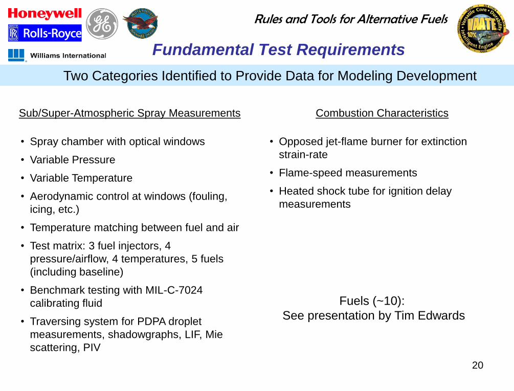
Fundamental Test Requirements
Two Categories Identified to Provide Data for Modeling Development
Sub/Super-Atmospheric Spray Measurements Combustion Characteristics
• Spray chamber with optical windows
• Variable Pressure
• Variable Temperature
• Aerodynamic control at windows (fouling,
icing, etc.)
• Temperature matching between fuel and air
• Test matrix: 3 fuel injectors, 4
pressure/airflow, 4 temperatures, 5 fuels
(including baseline)
• Benchmark testing with MIL-C-7024
calibrating fluid
• Traversing system for PDPA droplet
measurements, shadowgraphs, LIF, Mie
scattering, PIV
• Opposed jet-flame burner for extinction
strain-rate
• Flame-speed measurements
• Heated shock tube for ignition delay
measurements
Fuels (~10):
See presentation by Tim Edwards

Rules and Tools for Alternative Fuels
21 21
Modeling - Strategy
Need underlying physics, validation, and multiple tools, with
focus on fuel-type effects
Models for:
Spray
Kinetics
Altitude Relight
Lean Blow Off
Emissions
Combustion Dynamics
Model Classification:
Phenomenological
CFD
Hybrid Goal: create validated tool sets that can
explain observed fuel effects and,
eventually, to predict fuel impact on
combustor performance
A` . fpz . mA Dr2 D at TF
qLBO = –––––––––––––––––––– . –––––––– . [––––––––––––]2
Vc . P31.3 . exp (T3/300) r . LCVr D at 277.5K
To Saturator
Aftercooler
Saturator
Regenerator
Intercooler
To Saturator
Gas
Humid Air
Water
Air
Fig. 1. A schematic of the HAT cycle. Fig. 2. A schematic of the experimental set-up.
0
10
20
30
40
50
0.35 0.45 0.55 0.65
Equivalence ratio,
NO
x a
t 1
5%
O2 (
dry
), p
pm
0% pilot
1% pilot
3% pilot
5% pilot
Fig. 4. Comparison between measured NOx and computed
NOx at 200 psi at different pilot levels.
0
1 0
2 0
3 0
4 0
0 .3 5 0 .4 5 0 .5 5 0 .6 5
E qu iv a len c e ra tio ,
CO
at
15
% o
f O 2
(d
ry),
pp
m
0 % p ilo t
1 % p ilo t
3 % p ilo t
5 % p ilo t
Fig. 5. Comparison between measured CO and computed
CO at 200 psi at different pilot levels.
Fig. 3. A schematic of the PSR reactor network used to model the flame.
Premixed
fuel-air
0.3-1% Air21 9 14
1% Fuel3 1576 8
4
5
Rules and Tools for Alternative Fuels
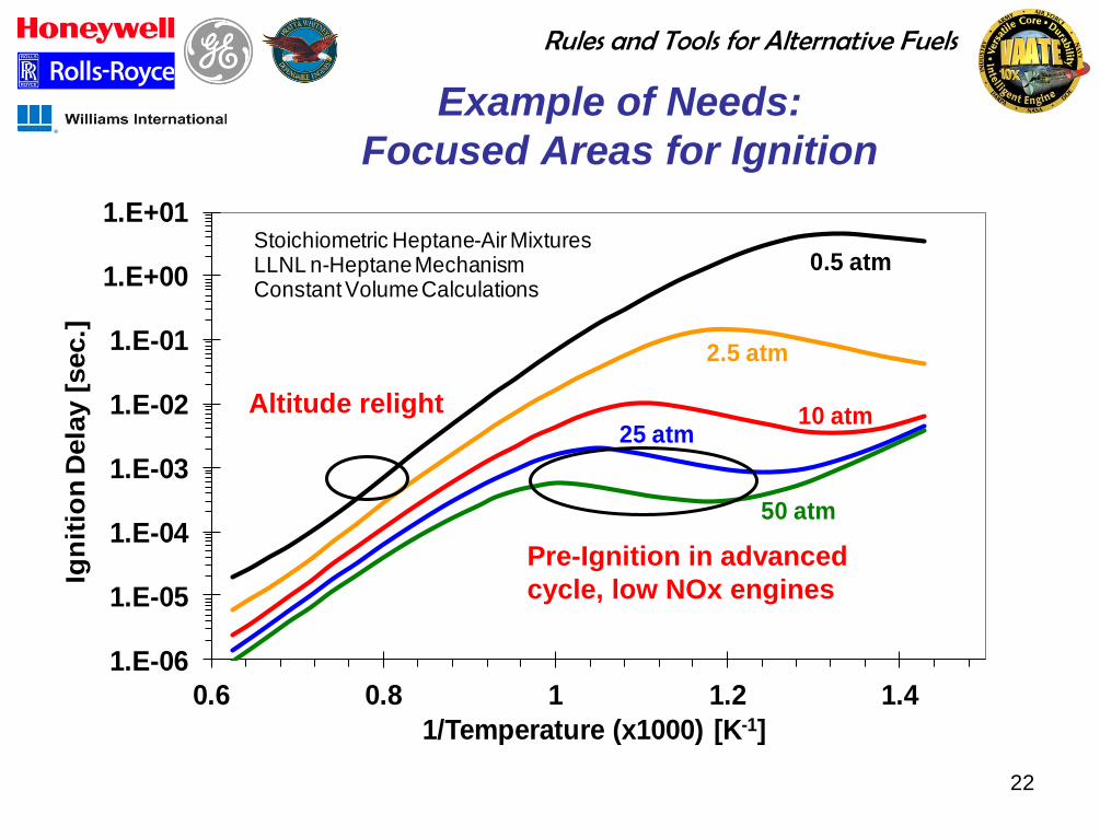
22
Example of Needs:
Focused Areas for Ignition
1.E-06
1.E-05
1.E-04
1.E-03
1.E-02
1.E-01
1.E+00
1.E+01
0.6 0.8 1 1.2 1.4
Ign
itio
n D
ela
y [
sec.]
1/Temperature (x1000) [K-1]
Stoichiometric Heptane-Air MixturesLLNL n-Heptane MechanismConstant Volume Calculations
0.5 atm
2.5 atm
10 atm25 atm
50 atm
Altitude relight
Pre-Ignition in advanced
cycle, low NOx engines
Rules and Tools for Alternative Fuels
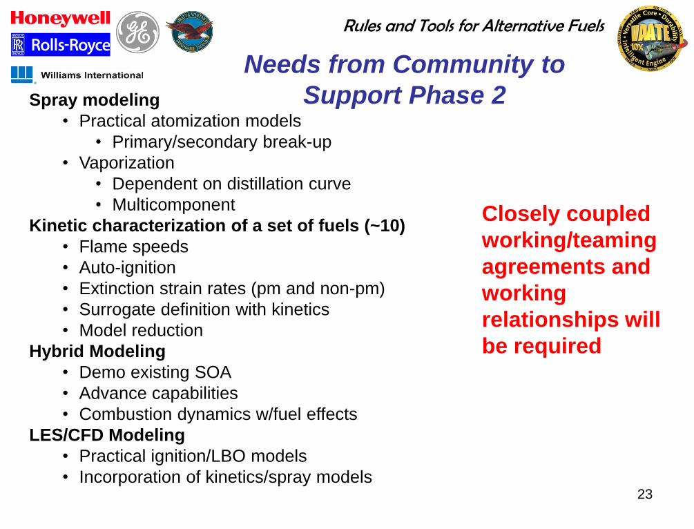
23
Needs from Community to
Support Phase 2 Spray modeling
• Practical atomization models
• Primary/secondary break-up
• Vaporization
• Dependent on distillation curve
• Multicomponent
Kinetic characterization of a set of fuels (~10)
• Flame speeds
• Auto-ignition
• Extinction strain rates (pm and non-pm)
• Surrogate definition with kinetics
• Model reduction
Hybrid Modeling
• Demo existing SOA
• Advance capabilities
• Combustion dynamics w/fuel effects
LES/CFD Modeling
• Practical ignition/LBO models
• Incorporation of kinetics/spray models
Closely coupled
working/teaming
agreements and
working
relationships will
be required
Rules and Tools for Alternative Fuels
24
Critical R&D Needs
Understanding of T5/T10/T50/T90 impact on ignition
and blow-off
Fuel effects on combustion dynamics
Validation of phenomenological models for post-1990
engines
Selection of surrogates – for broad range of properties
Validated chemical kinetics models
Efficient fuel-dependent sub-models for CFD
Validated spray models
Better understanding of aromatic effects
Fuel-dependent thermal stability models 24
Rules and Tools for Alternative Fuels
25
Summary
Comprehensive Phase 2 program plan developed
Expected duration is 3-4 years
Major tasks are: combustor testing, modeling and
fundamental testing for screening process
development
Close coordination amongst OEMs,
universities/small businesses and government
agencies will be required
Steering committees will be created to guide Phase
2 work
Rules and Tools for Alternative Fuels
26
Acknowledgements
Project would not have happened without:
Air Force Research Laboratory: Captain Wesley Anderson, Carlos
Arana, Vince Belovich, Edwin Corporan, Tim Edwards, Charles Frayne,
Robert Hancock, Captain Terry Hankins, Melvin Roquemore, and Balu
Sekar
Universal Technology Corporation: Clifford Moses and James Klein
AFRL & DESC for program funding
Rules and Tools for Alternative Fuels
27
QUESTIONS?
Rules and Tools for Alternative Fuels
28
Jet Fuel History
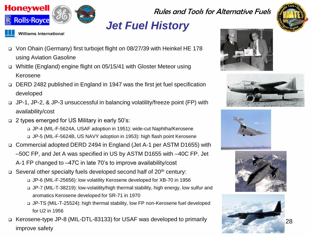
Von Ohain (Germany) first turbojet flight on 08/27/39 with Heinkel HE 178
using Aviation Gasoline
Whittle (England) engine flight on 05/15/41 with Gloster Meteor using
Kerosene
DERD 2482 published in England in 1947 was the first jet fuel specification
developed
JP-1, JP-2, & JP-3 unsuccessful in balancing volatility/freeze point (FP) with
availability/cost
2 types emerged for US Military in early 50‟s:
JP-4 (MIL-F-5624A, USAF adoption in 1951): wide-cut Naphtha/Kerosene
JP-5 (MIL-F-5624B, US NAVY adoption in 1953): high flash point Kerosene
Commercial adopted DERD 2494 in England (Jet A-1 per ASTM D1655) with
–50C FP, and Jet A was specified in US by ASTM D1655 with –40C FP. Jet
A-1 FP changed to –47C in late 70‟s to improve availability/cost
Several other specialty fuels developed second half of 20th century:
JP-6 (MIL-F-25656): low volatility Kerosene developed for XB-70 in 1956
JP-7 (MIL-T-38219): low-volatility/high thermal stability, high energy, low sulfur and
aromatics Kerosene developed for SR-71 in 1970
JP-TS (MIL-T-25524): high thermal stability, low FP non-Kerosene fuel developed
for U2 in 1956
Kerosene-type JP-8 (MIL-DTL-83133) for USAF was developed to primarily
improve safety
Rules and Tools for Alternative Fuels
29
Reference Fuel Set
• Category A reference fuels are motivated by need to characterize fuel effects that are
currently acceptable to the fleet within context of property distributions
Worst case JP-8 will set the boundary
Best case JP-8 will enable validation of proposed screening methodology
Nominal JP-8 will further add to our understanding of fuel property effects
• Category B reference fuels will provide an opportunity to using fuels in rigs that have
recently failed and passed engine-level evaluations
Recommendations include FAME (failed) and Sasol fully synthetic fuel (passed)
• Category C fuels will provide final check on defined process by testing whether or not it
will identify combustion effects due to property variation that is not currently covered by
fuel specifications, and to provide data necessary to extend models into these domains
Rules and Tools for Alternative Fuels
30
Transitions Costly and Time Consuming
Changes to baseline jet fuel or certification of new fuels/additive
JP-4 to JP-8 (Drastic Change) Long timeframe (~20 years)
Very costly…difficult to place an exact $ amount
Many challenges…root cause of leaks never truly determined…aromatics question not answered
JP-8+100 (Relatively small change) Long timeframe (~10 years)
Costly…estimated at $50M spent by DoD
Cleaning/lack of fouling on aircraft…reduced particulate emissions
Challenges: Not being able to take advantage of the increased heat sink, filter disarming
50% FT derived synthetic fuels, ASTM D7566 (Relatively small change) Relatively less time, but very costly
Only slightly different than Jet-A/JP-8 fuel…”drop-in”
Lower specific gravity, lower viscosity and little to no aromatic content
Engine manufacturers and industry testing laboratories have evaluated the physical and chemical
properties of the synthetic fuel
US military has spent 4+ years progressively testing the fuel with its inventory of engines and
airframes
Approval of 50:50 HRJ blends expected late 2011
Rules and Tools for Alternative Fuels
31
Technology Gaps and Missing
Correlations
Experimental ignition delay data on both current turbine fuel as well as potential fuels
Surrogate fuel development and validation
Type and minimum aromatic content
Evaluation of minimum density
More pure and high polycyclic containing materials need to be tested to explore the relationship to soot formation
Determine what chemical and/or physical property(ies) go with autoignition behavior, fuel reaction rate, and laminar flame speed
More development of fuel thermal stability prediction from chemical composition
Determine what chemical and/or physical property(ies) correlate between injector orifice behavior and fuel pressure