Embed Size (px)
Citation preview
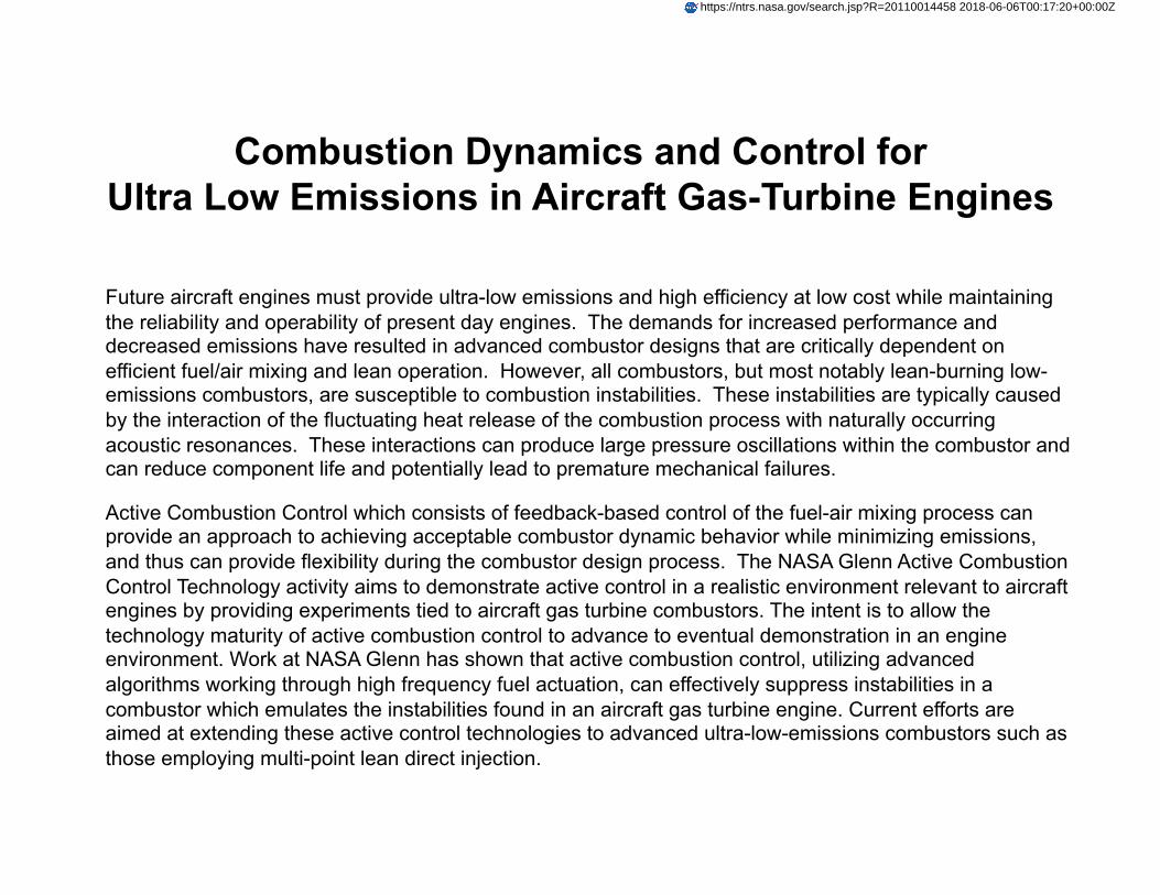
Combustion Dynamics and Control for Ultra Low Emissions in Aircraft Gas-Turbine Engines
Future aircraft engines must provide ultra-low emissions and high efficiency at low cost while maintaining the reliability and operability of present day engines. The demands for increased performance and decreased emissions have resulted in advanced combustor designs that are critically dependent on efficient fuel/air mixing and lean operation. However, all combustors, but most notably lean-burning low-emissions combustors, are susceptible to combustion instabilities. These instabilities are typically caused by the interaction of the fluctuating heat release of the combustion process with naturally occurring acoustic resonances. These interactions can produce large pressure oscillations within the combustor and can reduce component life and potentially lead to premature mechanical failures.
Active Combustion Control which consists of feedback-based control of the fuel-air mixing process can provide an approach to achieving acceptable combustor dynamic behavior while minimizing emissions, and thus can provide flexibility during the combustor design process. The NASA Glenn Active Combustion Control Technology activity aims to demonstrate active control in a realistic environment relevant to aircraft engines by providing experiments tied to aircraft gas turbine combustors. The intent is to allow the technology maturity of active combustion control to advance to eventual demonstration in an engine environment. Work at NASA Glenn has shown that active combustion control, utilizing advanced algorithms working through high frequency fuel actuation, can effectively suppress instabilities in a combustor which emulates the instabilities found in an aircraft gas turbine engine. Current efforts are aimed at extending these active control technologies to advanced ultra-low-emissions combustors such as those employing multi-point lean direct injection.
https://ntrs.nasa.gov/search.jsp?R=20110014458 2018-06-06T00:17:20+00:00Z
Combustion Dynamics and Control for Ultra Low Emissions infor Ultra Low Emissions in
Aircraft Gas-Turbine Engines
John DeLaatControls and Dynamics Branch
NASA Gl R h C t t L i Fi ld Cl l d OHNASA Glenn Research Center at Lewis Field, Cleveland, OHPh: (216) 433-3744, email: [email protected]
Graduate Seminar Series, The Ohio State UniversityMay 9, 2011
at Lewis FieldGlenn Research Center
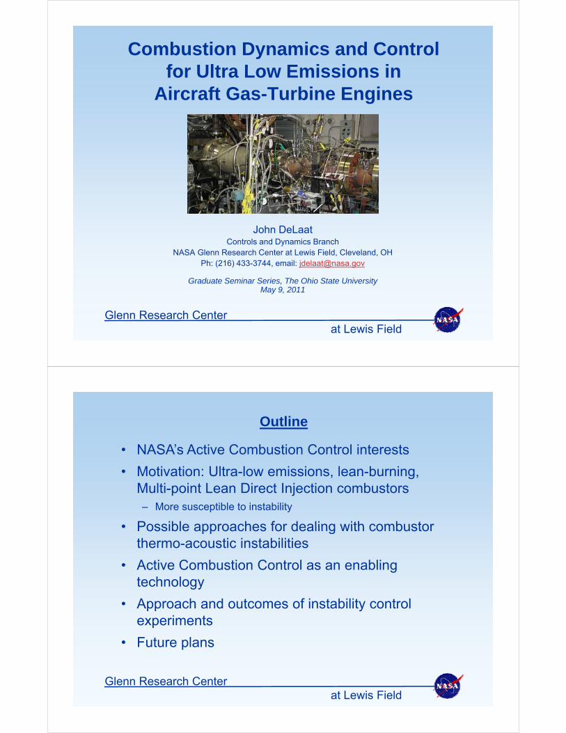
Outline
• NASA’s Active Combustion Control interests
• Motivation: Ultra-low emissions, lean-burning, Multi-point Lean Direct Injection combustors – More susceptible to instability
• Possible approaches for dealing with combustor• Possible approaches for dealing with combustor thermo-acoustic instabilities
• Active Combustion Control as an enabling gtechnology
• Approach and outcomes of instability control i texperiments
• Future plans
at Lewis FieldGlenn Research Center
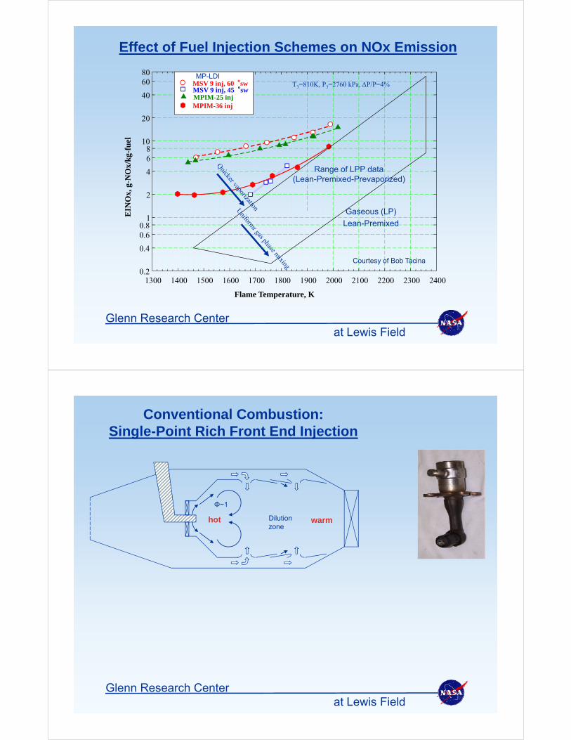
Effect of Fuel Injection Schemes on NOx Emission
80
20
40
6080
MSV 9 inj, 60 oswMSV 9 inj, 45 oswMPIM-25 injMPIM-36 inj
T3=810K, P3=2760 kPa, ΔP/P=4%MP-LDI
/kg-
fuel
68
10
20N
Ox,
g-N
Ox/
2
4 Range of LPP data(Lean-Premixed-Prevaporized)
EIN
0.4
0.60.8
1Gaseous (LP)
Lean-Premixed
Flame Temperature, K
1300 1400 1500 1600 1700 1800 1900 2000 2100 2200 2300 24000.2
Courtesy of Bob Tacina
at Lewis FieldGlenn Research Center
p ,
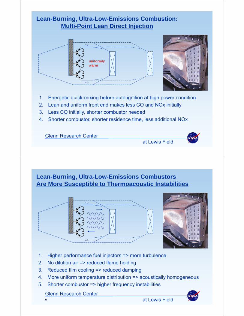
Conventional Combustion:Single-Point Rich Front End Injection
Φ~1
Dilutionzone
hot warm
at Lewis FieldGlenn Research Center
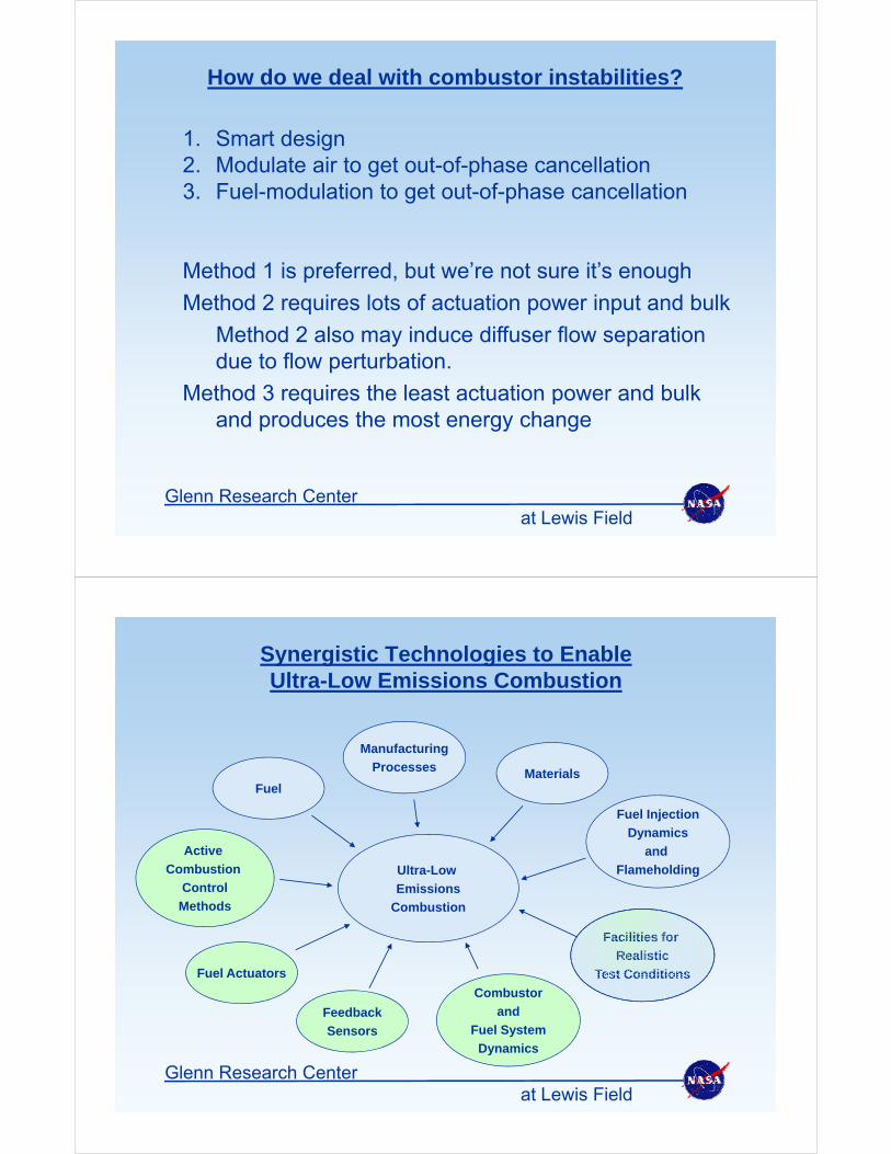
Lean-Burning, Ultra-Low-Emissions Combustion:Multi-Point Lean Direct Injection
uniformlywarm
1. Energetic quick-mixing before auto ignition at high power condition
2. Lean and uniform front end makes less CO and NOx initially
3. Less CO initially, shorter combustor needed
4. Shorter combustor, shorter residence time, less additional NOx
at Lewis FieldGlenn Research Center
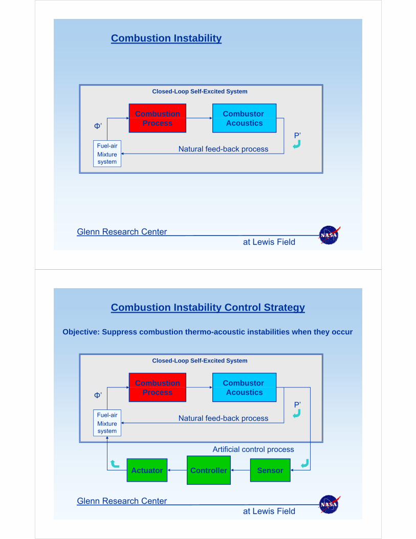
Lean-Burning, Ultra-Low-Emissions Combustors Are More Susceptible to Thermoacoustic Instabilities
1. Higher performance fuel injectors => more turbulence
2. No dilution air => reduced flame holding
3. Reduced film cooling => reduced damping
4. More uniform temperature distribution => acoustically homogeneous
5 Shorter combustor => higher frequency instabilities
at Lewis FieldGlenn Research Center6
5. Shorter combustor > higher frequency instabilities
How do we deal with combustor instabilities?
1. Smart design2. Modulate air to get out-of-phase cancellation3. Fuel-modulation to get out-of-phase cancellation
Method 1 is preferred, but we’re not sure it’s enough
Method 2 requires lots of actuation power input and bulk
Method 2 also may induce diffuser flow separation due to flow perturbation.
Method 3 requires the least actuation power and bulkMethod 3 requires the least actuation power and bulk and produces the most energy change
at Lewis FieldGlenn Research Center
Synergistic Technologies to Enable Ultra-Low Emissions CombustionUltra Low Emissions Combustion
Manufacturing
Fuel
Fuel Injection
D i
MaterialsProcesses
Ultra-Low
Emissions
Dynamics
and
Flameholding
Active
Combustion
Control
Combustion
Fuel Actuators
Methods
Facilities for
Realistic
T t C diti
Feedback
Sensors
Fuel Actuators
Combustor
and
Fuel System
Test Conditions
at Lewis FieldGlenn Research Center
Dynamics
Combustion Instability
Combustor Combustion
Closed-Loop Self-Excited System
AcousticsProcess
Natural feed-back processFuel-air
Φ’P’
Natural feed back processMixture system
at Lewis FieldGlenn Research Center
Combustion Instability Control Strategy
Objective: Suppress combustion thermo-acoustic instabilities when they occur
Combustor Combustion
Closed-Loop Self-Excited System
AcousticsProcess
Natural feed-back processFuel-air
Φ’P’
Natural feed back processMixture system
Artificial control process
SensorControllerActuator
at Lewis FieldGlenn Research Center
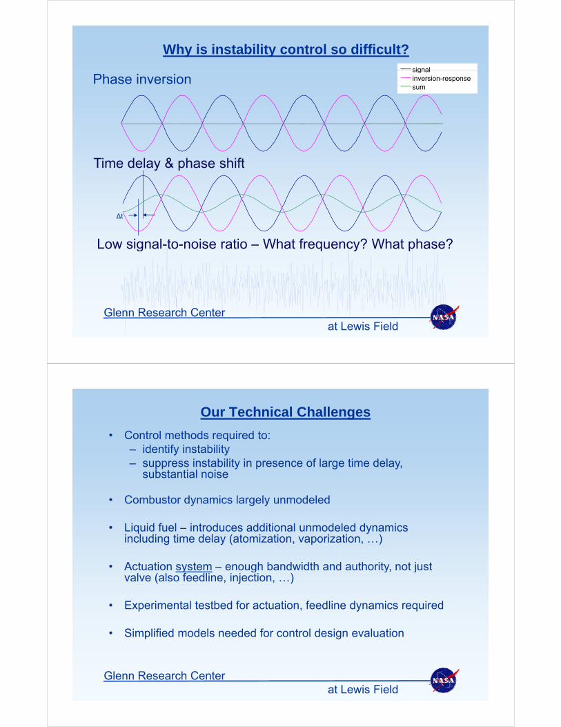
Why is instability control so difficult?signal
Phase inversionsignalinversion-responsesum
Ti d l & h hiftTime delay & phase shift
Low signal-to-noise ratio – What frequency? What phase?
∆t
Low signal to noise ratio What frequency? What phase?
at Lewis FieldGlenn Research Center
Our Technical Challenges
Control methods required to:• Control methods required to: – identify instability– suppress instability in presence of large time delay,
substantial noisesubstantial noise
• Combustor dynamics largely unmodeled
• Liquid fuel – introduces additional unmodeled dynamics including time delay (atomization, vaporization, …)
• Actuation system – enough bandwidth and authority not just• Actuation system – enough bandwidth and authority, not just valve (also feedline, injection, …)
• Experimental testbed for actuation, feedline dynamics required
• Simplified models needed for control design evaluation
at Lewis FieldGlenn Research Center
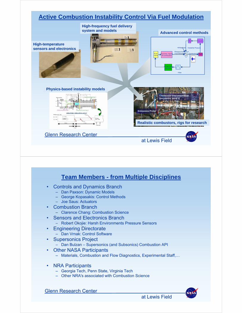
Active Combustion Instability Control Via Fuel Modulation
High-frequency fuel delivery system and modelssystem and models
•Acoustics•NL
•White Noise •Instability Pressure
Advanced control methods
High-temperature sensors and electronics
•Phase Shift•Controller
•Fuel •Valve
•Fuel lines, Injector•& Combustion •Flame
•+•+•+
•Pressure from•Fuel Modulation •Combustor Pressure
sensors and electronics
Ph i b d i t bilit d l
Controller
•Filter
S d b k
Combustor Instrumentation (pressures, temp’s)
Physics-based instability models
Fuel InjectorEmissions Probe
Realistic combustors, rigs for research
at Lewis FieldGlenn Research Center
Team Members - from Multiple Disciplines
• Controls and Dynamics Branch• Controls and Dynamics Branch– Dan Paxson: Dynamic Models– George Kopasakis: Control Methods– Joe Saus: Actuators
C b ti B h• Combustion Branch– Clarence Chang: Combustion Science
• Sensors and Electronics Branch– Robert Okojie: Harsh Environments Pressure Sensorsj
• Engineering Directorate– Dan Vrnak: Control Software
• Supersonics ProjectDan Bulzan Supersonics (and Subsonics) Combustion API– Dan Bulzan – Supersonics (and Subsonics) Combustion API
• Other NASA Participants– Materials, Combustion and Flow Diagnostics, Experimental Staff,…
• NRA Participants– Georgia Tech, Penn State, Virginia Tech – Other NRA's associated with Combustion Science
at Lewis FieldGlenn Research Center
Control Strategies to Deal with Combustion Instability
• Objective– Perturb the fuel with the right amplitude and at the right phase to
cancel the instabilityy
• Challenges– Control action delay, noise, unknown disturbancesy, ,
• Approach– Use reduced-order models for developmentp– Use simplified physics-based model for validation before test
• Control methods– Empirical: Adaptive phase shifting based on achieved cancellation– Model-based: Set the proper phase for cancellation based on a
model of the predicted instability and disturbances
at Lewis FieldGlenn Research Center
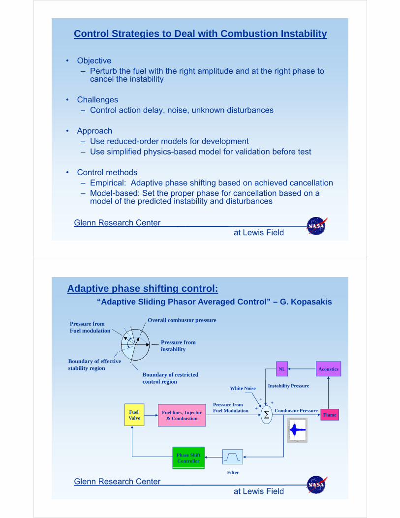
Adaptive phase shifting control:“Adaptive Sliding Phasor Averaged Control” – G. Kopasakis
P f
Pressure from Fuel modulation
Overall combustor pressure
AcousticsNL
Pressure from instability
Boundary of effective stability region
White Noise
++
Pressure from
Instability Pressure
Boundary of restricted control region
Fuel Valve
Fuel lines, Injector& Combustion Flame
++
Pressure fromFuel Modulation Combustor Pressure
Phase ShiftController
at Lewis FieldGlenn Research Center
Filter
Motivation for Combustion Instability Simulation
• Successful active control design requires accurate modeling andsimulation.
–The essential physical phenomena should be correctly captured• (e.g. self-excitation).
–Characterization and control design necessitate rapid simulationCharacterization and control design necessitate rapid simulation• (i.e. relative simplicity).
–Simulation must lend itself to implementing a variety of sensing andactuation strategiesactuation strategies.
• The developed simulation method must achieve these goals forcombustor configurations:combustor configurations:
– in which the potential instabilities propagate axially
– that contain abrupt changes in cross sectional area
at Lewis FieldGlenn Research Center
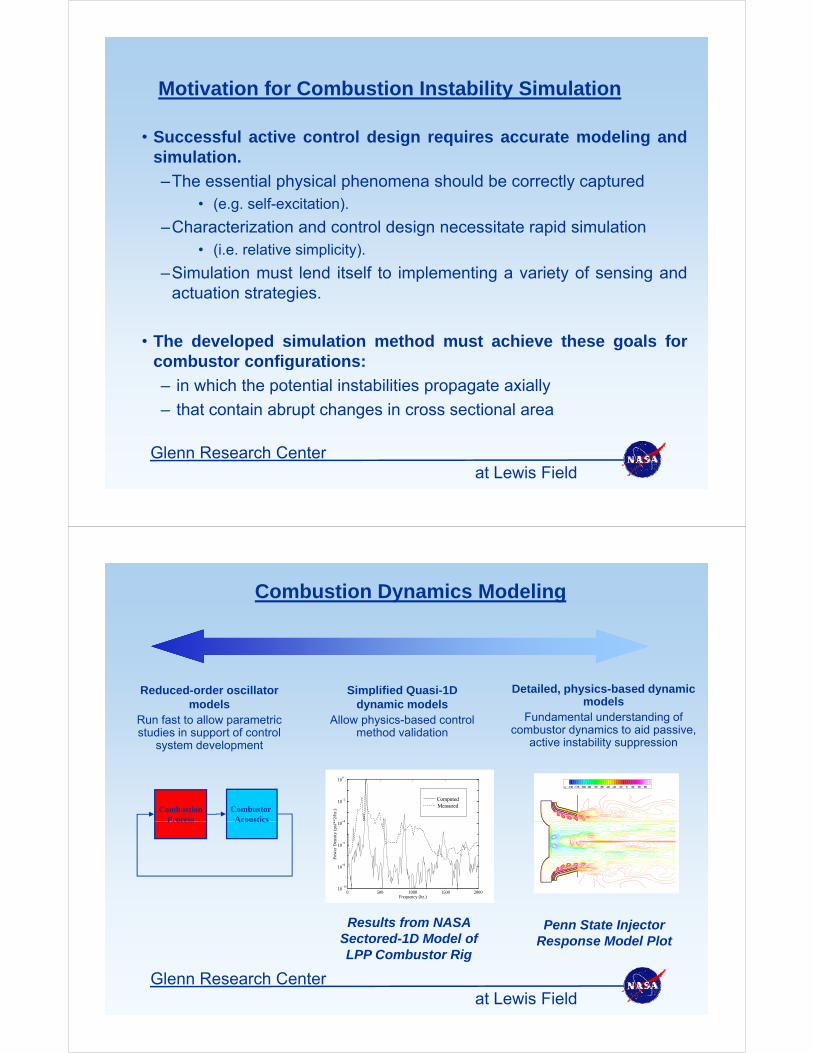
Combustion Dynamics Modeling
Detailed, physics-based dynamicSimplified Quasi-1DReduced-order oscillator Detailed, physics based dynamic models
Fundamental understanding of combustor dynamics to aid passive,
active instability suppression
Simplified Quasi 1D dynamic models
Allow physics-based control method validation
Reduced order oscillator models
Run fast to allow parametric studies in support of control
system development
vt: -130 -115 -100 -85 -70 -55 -40 -25 -10 5 20 35 50
10−4
10−2
100
i**2
/hz.
)
ComputedMeasuredCombustor
AcousticsCombustion
Process
−10
10−8
10−6
10−4
Pow
er D
ensi
ty (
psi*
*AcousticsProcess
Penn State Injector Response Model Plot
Results from NASA Sectored-1D Model of LPP C b t Ri
0 500 1000 1500 200010
−10
Frequency (hz.)
at Lewis FieldGlenn Research Center
LPP Combustor Rig
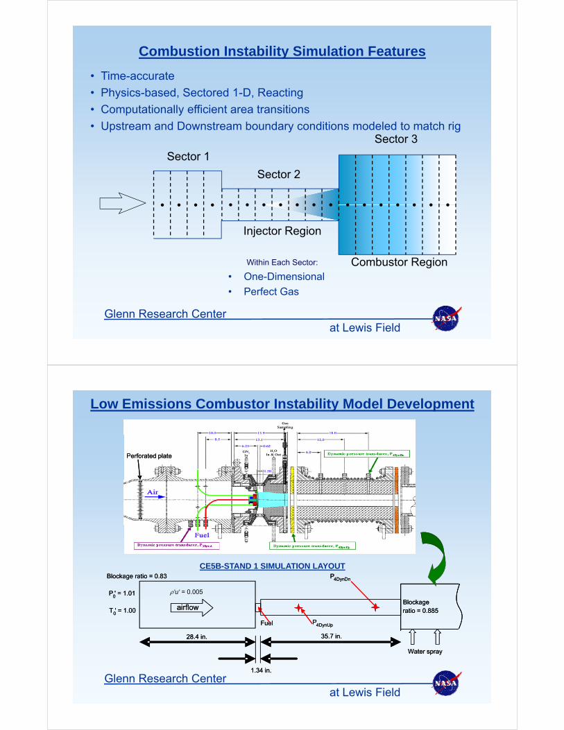
Combustion Instability Simulation Features
• Time-accurate
• Physics-based, Sectored 1-D, Reacting
• Computationally efficient area transitions
Sector 3
Sector 1
p y
• Upstream and Downstream boundary conditions modeled to match rig
Sector 2
Sector 1
Injector Region
• One-Dimensional
• Perfect Gas
Within Each Sector: Combustor Region
at Lewis FieldGlenn Research Center
Perfect Gas
Low Emissions Combustor Instability Model Development
Perforated platePerforated plate
CE5B-STAND 1 SIMULATION LAYOUT
airflow
Blockage ratio = 0.83
P0' = 1.01
T0' = 1.00
P4DynDn
Blockage ratio = 0.885airflow
Blockage ratio = 0.83
P0' = 1.01
T0' = 1.00
'u' = 0.005
P4DynDn
Blockage ratio = 0.885
P4DynUpFuel
0
28.4 in. 35.7 in.
Water spray
P4DynUpFuel
0
28.4 in. 35.7 in.
Water spray
at Lewis FieldGlenn Research Center
1.34 in.1.34 in.
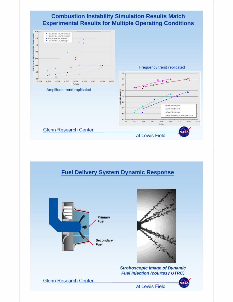
Combustion Instability Simulation Results Match Experimental Results for Multiple Operating Conditions
•1.0
•1.2
•1.4lit
y F
requ
ency
(ps
i) •Exp.-P3=250 psia, T3=1000degF
•Sim.-P3=250 psia, T3=1000degF
•Exp.-P3=166 psia, 1000degF
•Sim.-P3=166 psia, 1000degF
F t d li t d•0.4
•0.6
•0.8
ynD
n A
mpl
itude
at
Inst
abi
Frequency trend replicated
•0.0
•0.2
•0.024 •0.025 •0.026 •0.027 •0.028 •0.029 •0.03 •0.031 •0.032
•f/a Ratio
•P4D
y
Amplitude trend replicated
at Lewis FieldGlenn Research Center
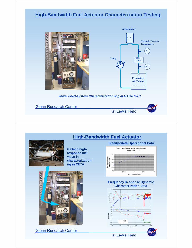
Fuel Delivery System Dynamic Response
PrimaryPrimaryFuel
SecondaryFuel
Stroboscopic Image of Dynamic Fuel Injection (courtesy UTRC)
at Lewis FieldGlenn Research Center
Fuel Injection (courtesy UTRC)
High-Bandwidth Fuel Actuator Characterization Testing
Accumulator
P
Dynamic PressureTransducers
TestValve
P
Pump
PressurizedAir Volume
Valve, Feed-system Characterization Rig at NASA GRC
at Lewis FieldGlenn Research Center
Steady-State Operational Data
High-Bandwidth Fuel Actuator
GaTech high-response fuel valve in characterization rig in CE7A
Frequency Response Dynamic Characterization Data
0.2
0
0.05
0.1
0.15
DP23
a/in
put, p
si/v
olt
360
-900
-720
-540
-360
-180
0
180
Pha
se, de
g
0ft-1V
1ft-1V
2ft-1V
at Lewis FieldGlenn Research Center
-1080
0 500 1000 1500 2000 2500
Frequency, Hz
High-Bandwidth Fuel Actuator
300Hz 600Hz
Combustor Pressure Response to Fuel Modulation
1.5
olt
s
RefAcmd
Max=1.45 @ 600.59Hz, PSD RMS=1.3
Run 208, 020529 , Point 65
1
2
olt
s
Time RMS=1.06, Mean=0
1.5
olt
s
RefAcmd
Max=1.49 @ 300.29Hz, PSD RMS=1.3
Run 208, 020529 , Point 62
1
2
olt
s
Time RMS=1.06, Mean=0
0
0.5
1
Am
pli
tud
e, v
o
-2
-1
0
1
Am
pli
tud
e, v
o
0
0.5
1
Am
pli
tud
e, v
o
-2
-1
0
1
Am
pli
tud
e, v
o
0.2
0.3
0.4
itu
de,
psi
pla1c1
Max=0.25 @ 600.59Hz, PSD RMS=1.16
0
2
4
itu
de,
psi
Time RMS=0.95, Mean=0
0.4
0.6
0.8
itu
de,
psi
pla1c1
Max=0.55 @ 300.29Hz, PSD RMS=1.24
0
2
4
itu
de,
psi
Time RMS=1.02, Mean=0
0 500 10000
0.1
Am
pli
Frequency, Hz0 0.01 0.02 0.03 0.04
-4
-2
Am
pli
Time, sec0 500 1000
0
0.2
Am
pli
Frequency, Hz0 0.01 0.02 0.03 0.04
-4
-2
Am
pli
Time, sec
at Lewis FieldGlenn Research Center
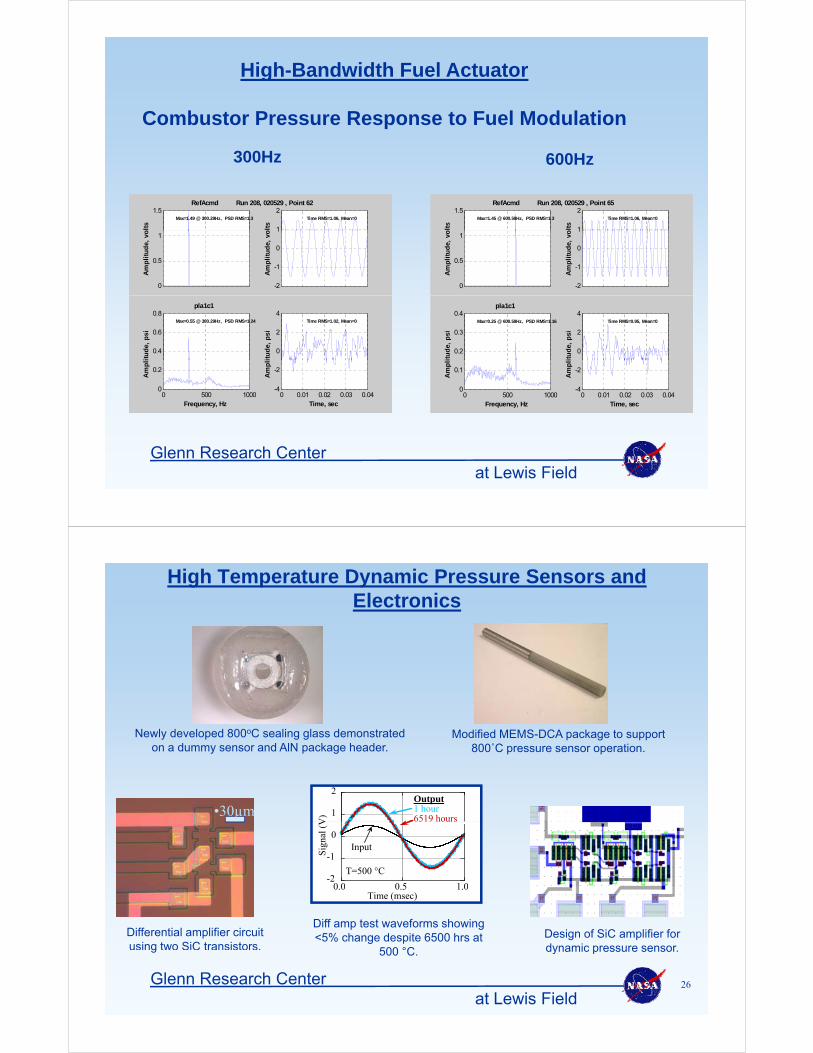
High Temperature Dynamic Pressure Sensors and Electronics
Newly developed 800oC sealing glass demonstrated on a dummy sensor and AlN package header.
Modified MEMS-DCA package to support 800˚C pressure sensor operation.
•30µm 1
2
V)
Output1 hour6519 hours
-2
-1
0
0 0 0 5 1 0
Sig
nal (
V
Input
6519 hours
T=500 °C
Diff amp test waveforms showing <5% change despite 6500 hrs at
500 °C
0.0 0.5 1.0Time (msec)
Differential amplifier circuit using two SiC transistors.
Design of SiC amplifier for dynamic pressure sensor.
at Lewis FieldGlenn Research Center 26
500 C. g dynamic pressure sensor.
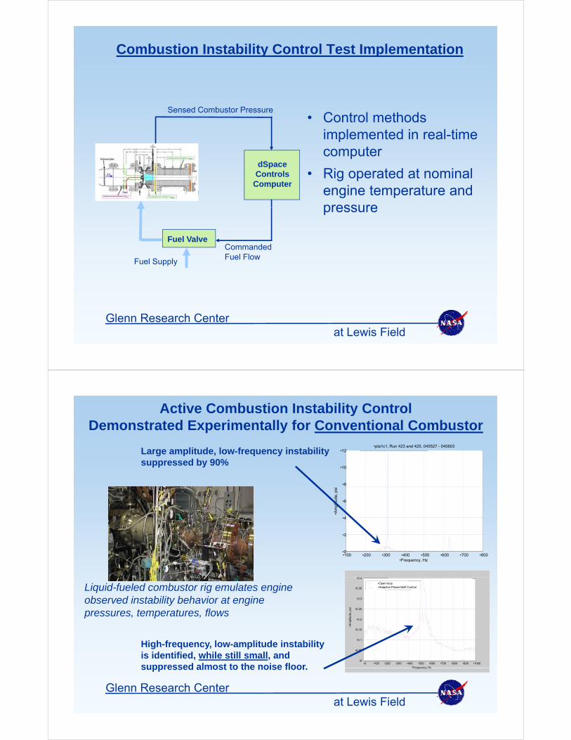
Combustion Instability Control Test Implementation
• Control methodsSensed Combustor Pressure
• Control methods implemented in real-time computer
dS• Rig operated at nominal
engine temperature and pressure
dSpace Controls
Computer
pressure
Fuel ValveCommanded Fuel FlowFuel Supply
at Lewis FieldGlenn Research Center
Active Combustion Instability Control Demonstrated Experimentally for Conventional Combustor
•8
•10
•12•pla1c1, Run 423 and 425, 040527 - 040603
Large amplitude, low-frequency instability suppressed by 90%
•4
•6
•Am
plitu
de, p
si
•100 •200 •300 •400 •500 •600 •700 •800•0
•2
•Frequency, Hz
0 4
Liquid-fueled combustor rig emulates engine observed instability behavior at engine pressures, temperatures, flows
•0.2
•0.25
•0.3
•0.35
•0.4
mpl
itude
, psi
•Open-loop•Adaptive Phase-Shift Control
High-frequency, low-amplitude instability is identified, while still small, and suppressed almost to the noise floor
•0 •100 •200 •300 •400 •500 •600 •700 •800 •900 •1000•0
•0.05
•0.1
•0.15
•Am
•Frequency Hz
at Lewis FieldGlenn Research Center
suppressed almost to the noise floor. Frequency, Hz
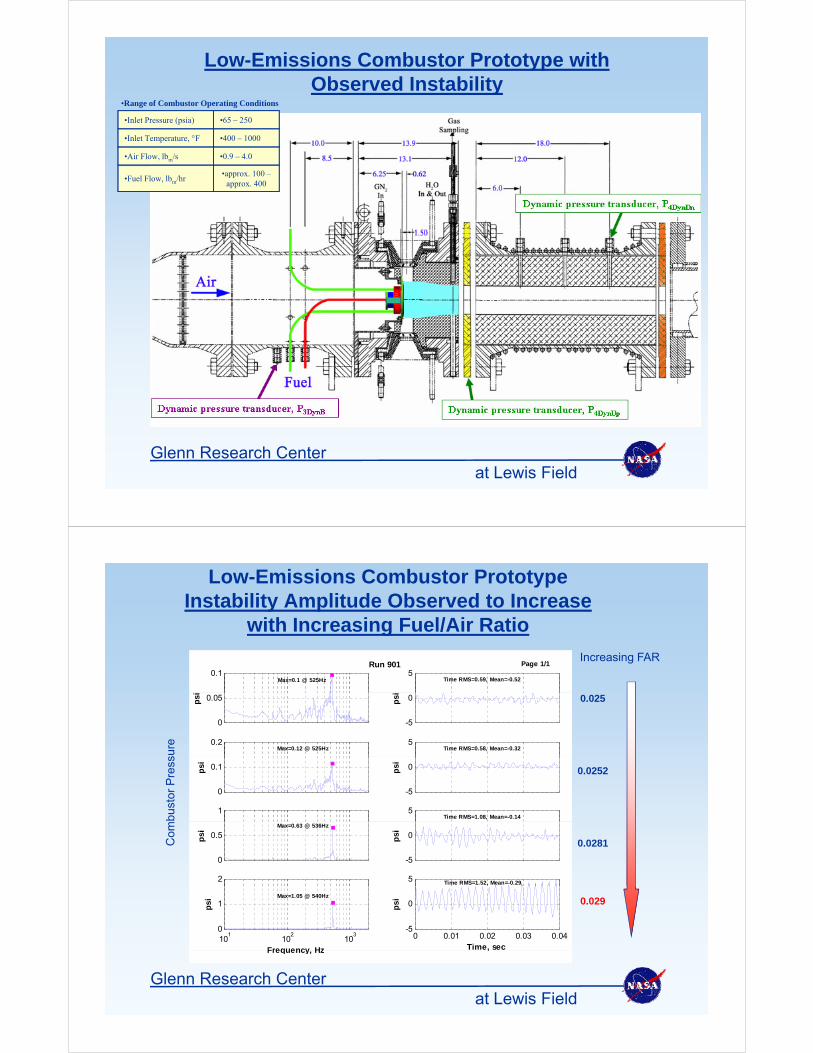
Low-Emissions Combustor Prototype with Observed Instability
R f C b t O ti C diti•Range of Combustor Operating Conditions
•0.9 – 4.0•Air Flow, lbm/s
•400 – 1000•Inlet Temperature, F
•65 – 250•Inlet Pressure (psia)
•approx. 100 –approx. 400
•Fuel Flow, lbm/hr
at Lewis FieldGlenn Research Center
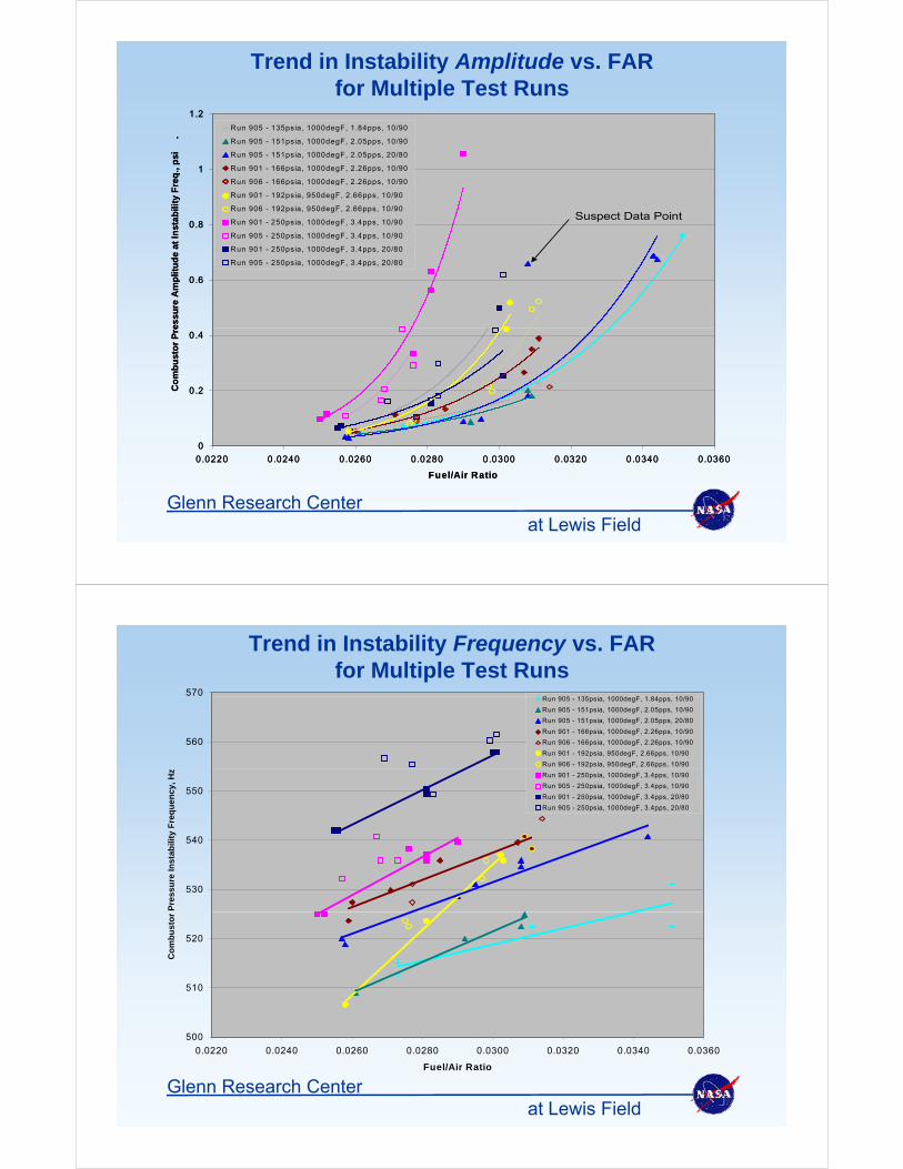
Low-Emissions Combustor PrototypeInstability Amplitude Observed to Increase
with Increasing Fuel/Air Ratio
Increasing FAR0.1
Max=0.1 @ 525Hz5
Time RMS=0.59, Mean=-0.52
Page 1/1Run 901
with Increasing Fuel/Air Ratio
sure
0.025
0
0.05psi
-5
0psi
0.2Max=0.12 @ 525Hz
5Time RMS=0.58, Mean=-0.32
bust
or P
ress
0.0252
0
0.1psi
-5
0psi
1 5Time RMS=1.08, Mean=-0.14
Com
0.0281
0
0.5psi
Max=0.63 @ 536Hz
-5
0psi
2 5 Time RMS=1.52, Mean=-0.29
0.029
101
102
103
0
1psi
Frequency Hz
Max=1.05 @ 540Hz
0 0.01 0.02 0.03 0.04-5
0psi
Time, sec
at Lewis FieldGlenn Research Center
Frequency, Hz ,
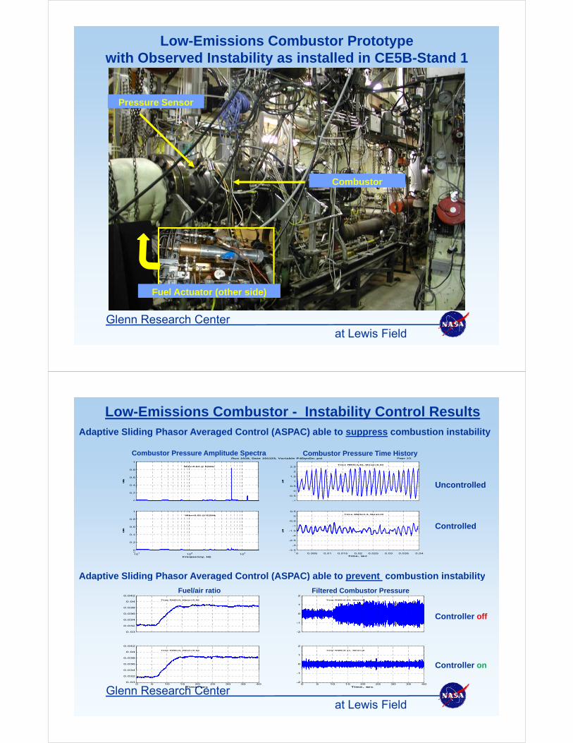
Trend in Instability Amplitude vs. FARfor Multiple Test Runs
1 21 2
1
1.2
req
., p
si
.
Run 905 - 135psia, 1000degF, 1.84pps, 10/90
Run 905 - 151psia, 1000degF, 2.05pps, 10/90
Run 905 - 151psia, 1000degF, 2.05pps, 20/80
Run 901 - 166psia, 1000degF, 2.26pps, 10/90
Run 906 - 166psia, 1000degF, 2.26pps, 10/90
1
1.2
req
., p
si
.
Run 905 - 135psia, 1000degF, 1.84pps, 10/90
Run 905 - 151psia, 1000degF, 2.05pps, 10/90
Run 905 - 151psia, 1000degF, 2.05pps, 20/80
Run 901 - 166psia, 1000degF, 2.26pps, 10/90
Run 906 - 166psia, 1000degF, 2.26pps, 10/90
0.8
e at
Inst
abili
ty F
r p , g , pp ,
Run 901 - 192psia, 950degF, 2.66pps, 10/90
Run 906 - 192psia, 950degF, 2.66pps, 10/90
Run 901 - 250psia, 1000degF, 3.4pps, 10/90
Run 905 - 250psia, 1000degF, 3.4pps, 10/90
Run 901 - 250psia, 1000degF, 3.4pps, 20/80
Suspect Data Point0.8
e at
Inst
abili
ty F
r p , g , pp ,
Run 901 - 192psia, 950degF, 2.66pps, 10/90
Run 906 - 192psia, 950degF, 2.66pps, 10/90
Run 901 - 250psia, 1000degF, 3.4pps, 10/90
Run 905 - 250psia, 1000degF, 3.4pps, 10/90
Run 901 - 250psia, 1000degF, 3.4pps, 20/80
Suspect Data Point
0.6
essu
re A
mp
litu
de
Run 905 - 250psia, 1000degF, 3.4pps, 20/80
0.6
essu
re A
mp
litu
de
Run 905 - 250psia, 1000degF, 3.4pps, 20/80
0.2
0.4
Co
mb
ust
or
Pre
0.2
0.4
Co
mb
ust
or
Pre
0
0.0220 0.0240 0.0260 0.0280 0.0300 0.0320 0.0340 0.0360
0
0.0220 0.0240 0.0260 0.0280 0.0300 0.0320 0.0340 0.0360
at Lewis FieldGlenn Research Center
Fuel/Air RatioFuel/Air Ratio
Trend in Instability Frequency vs. FARfor Multiple Test Runs
570R 905 135 i 1000d F 1 84 10/90
560
Run 905 - 135psia, 1000degF, 1.84pps, 10/90
Run 905 - 151psia, 1000degF, 2.05pps, 10/90
Run 905 - 151psia, 1000degF, 2.05pps, 20/80
Run 901 - 166psia, 1000degF, 2.26pps, 10/90
Run 906 - 166psia, 1000degF, 2.26pps, 10/90
Run 901 - 192psia, 950degF, 2.66pps, 10/90
Run 906 - 192psia, 950degF, 2.66pps, 10/90
540
550
ity
Fre
qu
en
cy
, H
z
Run 901 - 250psia, 1000degF, 3.4pps, 10/90
Run 905 - 250psia, 1000degF, 3.4pps, 10/90
Run 901 - 250psia, 1000degF, 3.4pps, 20/80
Run 905 - 250psia, 1000degF, 3.4pps, 20/80
530
540
Pre
ssu
re In
sta
bil
i
520
Co
mb
us
tor
500
510
0.0220 0.0240 0.0260 0.0280 0.0300 0.0320 0.0340 0.0360
at Lewis FieldGlenn Research Center
Fuel/Air Ratio
Low-Emissions Combustor Prototype with Observed Instability as installed in CE5B-Stand 1
Pressure Sensor
Combustor
Fuel Actuator (other side)
at Lewis FieldGlenn Research Center
Low-Emissions Combustor - Instability Control ResultsAdaptive Sliding Phasor Averaged Control (ASPAC) able to suppress combustion instability
Uncontrolled
Combustor Pressure Amplitude Spectra Combustor Pressure Time HistoryRun 1018, Date 101123, Variable P4DynDn_psi Page 1/1
0.4
0.6
0.8
1
045
Max=0.84 @ 626Hz
0.5
1
1.5
2
2.5
psi
Time RMS=1.61, Mean=0.33
Controlled0 4
0.6
0.8
1
044
Max=0.05 @ 629Hz
-1.5
-1
-0.5
0
0.5
psi
Time RMS=1.3, Mean=0
0
0.2
-1
-0.5
0
Adaptive Sliding Phasor Averaged Control (ASPAC) able to prevent combustion instability
0
0.2
0.4
-3.5
-3
-2.5
-2
101
102
103
0
Frequency, Hz
0 0.005 0.01 0.015 0.02 0.025 0.03 0.035 0.041
Time, sec
-1
0
1
2
Time RMS=0.54, Mean=0
0 032
0.034
0.036
0.038
0.04
0.042
Time RMS=0, Mean=0.04
Fuel/air ratio Filtered Combustor Pressure
Controller off
p g g ( ) p y
Controller on
-2
0
1
2
Time RMS=0.11, Mean=0
0.03
0.032
0.034
0.036
0.038
0.04
0.042
Time RMS=0, Mean=0.04
at Lewis FieldGlenn Research Center
0 5 10 15 20 25 30 35 40-2
-1
Time, sec0 5 10 15 20 25 30 35 40
0.03
0.032
0.034
Time, sec
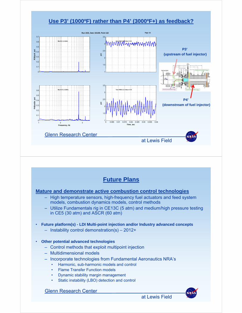
Use P3’ (1000ºF) rather than P4’ (3000ºF+) as feedback?
0.5
0.6
0.7
Max=0.2 @ 626Hz
3
3.5
Time RMS=0.96, Mean=-0.01
Run 1015, Date 101109, Point 122 Page 1/1
P3’
0.1
0.2
0.3
0.4
P3D
ynA
_psi
1.5
2
2.5
psi
P3
(upstream of fuel injector)
0 1
3.5
0.3
0.4
0.5
0.6
4Dyn
Dn
_psi
Max=0.57 @ 626Hz
2
2.5
3
psi
Time RMS=1.15, Mean=-0.33
P4’
(downstream of fuel injector)
1 2 30
0.1
0.2
P4
Frequency, Hz
0 0.005 0.01 0.015 0.02 0.025 0.03 0.035 0.041
1.5
Time, sec
at Lewis FieldGlenn Research Center
y
Future Plans
Mature and demonstrate active combustion control technologies– High temperature sensors, high-frequency fuel actuators and feed system
models, combustion dynamics models, control methods– Utilize Fundamentals rig in CE13C (5 atm) and medium/high pressure testing
in CE5 (30 atm) and ASCR (60 atm)
• Future platform(s) - LDI Multi-point injection and/or Industry advanced conceptsFuture platform(s) - LDI Multi-point injection and/or Industry advanced concepts
– Instability control demonstration(s) – 2012+
• Other potential advanced technologies
– Control methods that exploit multipoint injection– Multidimensional models– Incorporate technologies from Fundamental Aeronautics NRA’s
H i b h i d l d t l• Harmonic, sub-harmonic models and control• Flame Transfer Function models• Dynamic stability margin management• Static instability (LBO) detection and control
at Lewis FieldGlenn Research Center
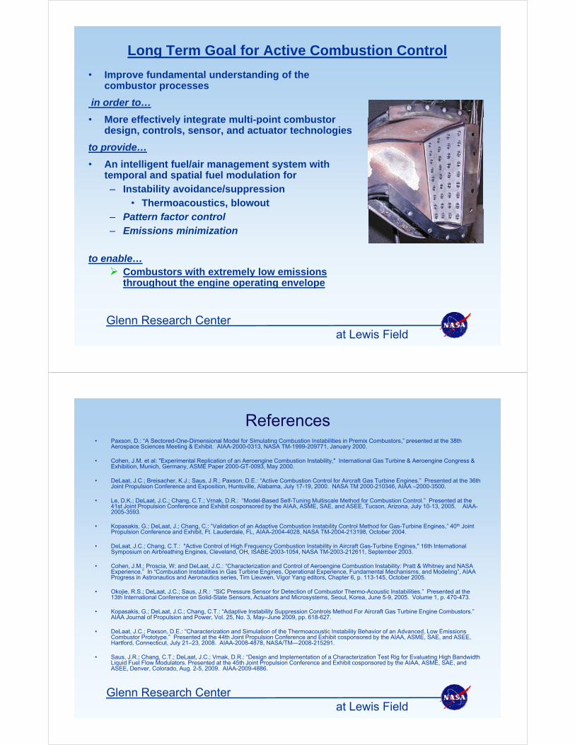
Long Term Goal for Active Combustion Control
I f d t l d t di f th• Improve fundamental understanding of the combustor processes
in order to…
More effectively integrate multi point combustor• More effectively integrate multi-point combustor design, controls, sensor, and actuator technologies
to provide…
• An intelligent fuel/air management system with• An intelligent fuel/air management system with temporal and spatial fuel modulation for– Instability avoidance/suppression
• Thermoacoustics, blowout– Pattern factor control– Emissions minimization
blto enable… Combustors with extremely low emissions
throughout the engine operating envelope
at Lewis FieldGlenn Research Center
References• Paxson, D.: “A Sectored-One-Dimensional Model for Simulating Combustion Instabilities in Premix Combustors,” presented at the 38th
Aerospace Sciences Meeting & Exhibit. AIAA-2000-0313, NASA TM-1999-209771, January 2000.
• Cohen, J.M. et al: "Experimental Replication of an Aeroengine Combustion Instability," International Gas Turbine & Aeroengine Congress & Exhibition, Munich, Germany, ASME Paper 2000-GT-0093, May 2000.
• DeLaat, J.C.; Breisacher, K.J.; Saus, J.R.; Paxson, D.E.: “Active Combustion Control for Aircraft Gas Turbine Engines.” Presented at the 36th Joint Propulsion Conference and Exposition, Huntsville, Alabama, July 17-19, 2000. NASA TM 2000-210346, AIAA –2000-3500.
• Le, D.K.; DeLaat, J.C.; Chang, C.T.; Vrnak, D.R.: “Model-Based Self-Tuning Multiscale Method for Combustion Control.” Presented at the 41st Joint Propulsion Conference and Exhibit cosponsored by the AIAA, ASME, SAE, and ASEE, Tucson, Arizona, July 10-13, 2005. AIAA-2005-3593.
• Kopasakis, G.; DeLaat, J.; Chang, C.: “Validation of an Adaptive Combustion Instability Control Method for Gas-Turbine Engines,” 40th Joint Propulsion Conference and Exhibit, Ft. Lauderdale, FL, AIAA-2004-4028, NASA TM-2004-213198, October 2004.
• DeLaat, J.C.; Chang, C.T.: "Active Control of High Frequency Combustion Instability in Aircraft Gas-Turbine Engines," 16th International Symposium on Airbreathing Engines, Cleveland, OH, ISABE-2003-1054, NASA TM-2003-212611, September 2003.
• Cohen, J.M.; Proscia, W; and DeLaat, J.C.: “Characterization and Control of Aeroengine Combustion Instability: Pratt & Whitney and NASA Experience.” In “Combustion Instabilities in Gas Turbine Engines, Operational Experience, Fundamental Mechanisms, and Modeling”, AIAA Progress in Astronautics and Aeronautics series, Tim Lieuwen, Vigor Yang editors, Chapter 6, p. 113-145, October 2005.
• Okojie, R.S.; DeLaat, J.C.; Saus, J.R.: “SiC Pressure Sensor for Detection of Combustor Thermo-Acoustic Instabilities.” Presented at the 13th International Conference on Solid-State Sensors, Actuators and Microsystems, Seoul, Korea, June 5-9, 2005. Volume 1, p. 470-473.
• Kopasakis, G.; DeLaat, J.C.; Chang, C.T.: “Adaptive Instability Suppression Controls Method For Aircraft Gas Turbine Engine Combustors.” AIAA Journal of Propulsion and Power, Vol. 25, No. 3, May–June 2009, pp. 618-627.
• DeLaat, J.C.; Paxson, D.E.: “Characterization and Simulation of the Thermoacoustic Instability Behavior of an Advanced, Low Emissions Combustor Prototype.” Presented at the 44th Joint Propulsion Conference and Exhibit cosponsored by the AIAA, ASME, SAE, and ASEE, Hartford, Connecticut, July 21–23, 2008. AIAA-2008-4878, NASA/TM—2008-215291.
• Saus, J.R.; Chang, C.T.; DeLaat, J.C.; Vrnak, D.R.: “Design and Implementation of a Characterization Test Rig for Evaluating High Bandwidth Liquid Fuel Flow Modulators. Presented at the 45th Joint Propulsion Conference and Exhibit cosponsored by the AIAA, ASME, SAE, and ASEE, Denver, Colorado, Aug. 2-5, 2009. AIAA-2009-4886.
at Lewis FieldGlenn Research Center
Questions?Questions?
at Lewis FieldGlenn Research Center