Embed Size (px)
Citation preview
LTC University ConsortiumLTC University Consortium
University Consortium
University of MichiganMassachusetts Institute of Technology
Stanford UniversityUniversity of California, Berkeley
Dennis Assanis (UM)
12th Diesel Engine-Efficiency and Emissions Research (DEER) ConferenceAugust 20-24, 2006, Detroit, Michigan
Low-Temperature Combustion for High-Efficiency,Ultra-Low Emission Engines
LTC University ConsortiumLTC University Consortium
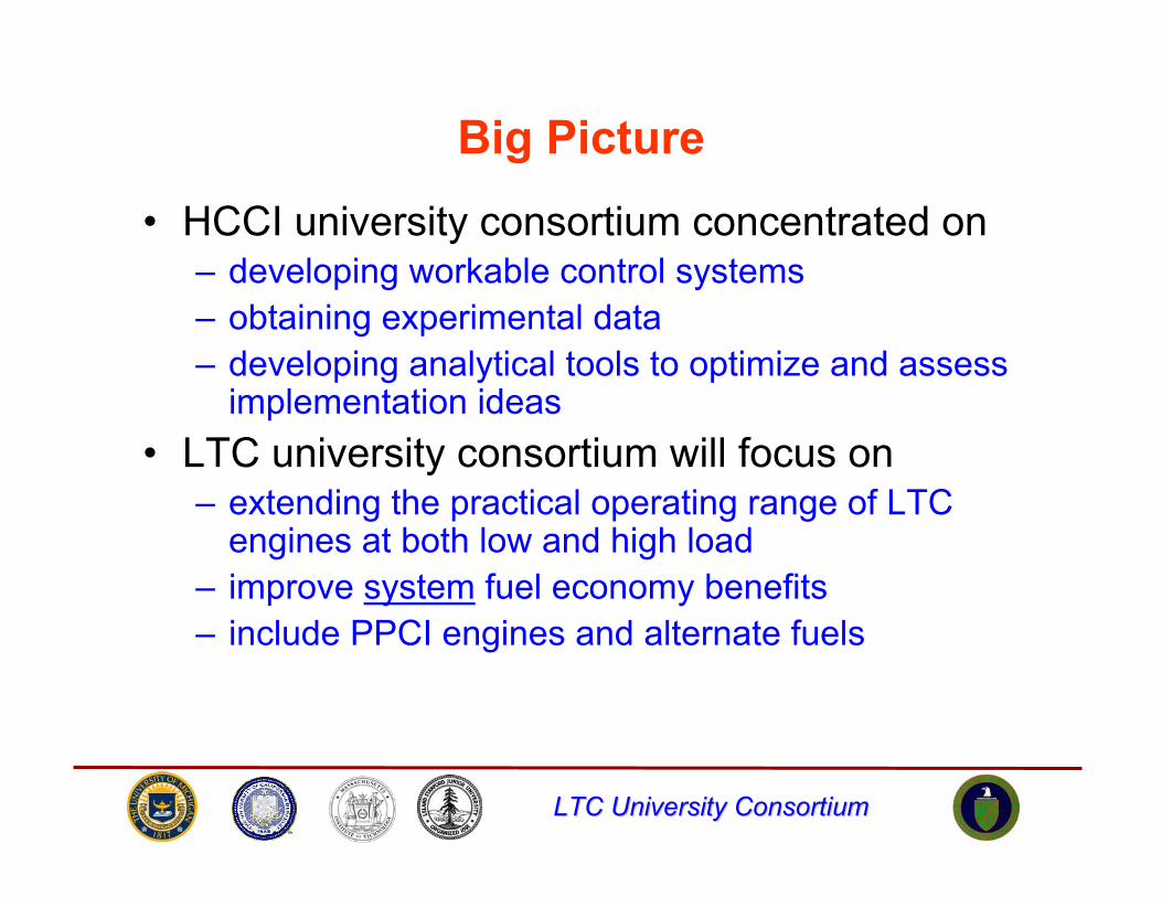
Big Picture
• HCCI university consortium concentrated on– developing workable control systems– obtaining experimental data– developing analytical tools to optimize and assess
implementation ideas• LTC university consortium will focus on
– extending the practical operating range of LTC engines at both low and high load
– improve system fuel economy benefits– include PPCI engines and alternate fuels
LTC University ConsortiumLTC University Consortium
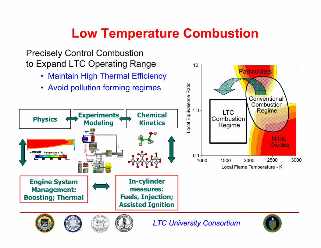
Low Temperature CombustionPrecisely Control Combustionto Expand LTC Operating Range
• Maintain High Thermal Efficiency• Avoid pollution forming regimes
PhysicsExperiments
ModelingChemical Kinetics
Engine System Management:
Boosting; Thermal
In-cylinder measures:
Fuels, Injection; Assisted Ignition
FuelVaporizer
N2
Intake Canister
SCV valve
Heater
External EGR Line
ExhaustCanister
ThrottlePlate
Air Cleaner
FuelTank
Accumulator
Direct Injection
Fully
Pre
mix
ed
HydraulicDYNO
MechanicalTelemetry
Exhaust Gate Valve
FuelVaporizer
N2
Intake Canister
SCV valve
Heater
External EGR Line
ExhaustCanister
ThrottlePlate
Air Cleaner
FuelTank
Accumulator
Direct Injection
Fully
Pre
mix
ed
HydraulicDYNO
MechanicalTelemetry
Exhaust Gate Valve
LTC University ConsortiumLTC University Consortium
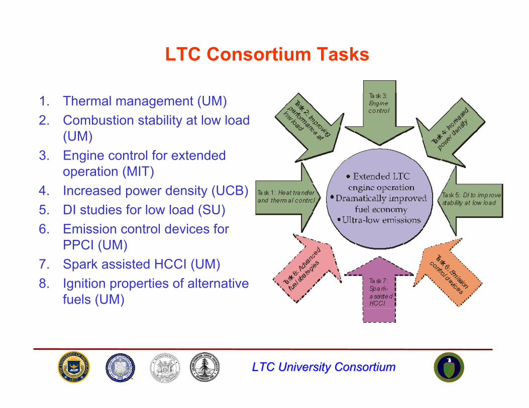
LTC Consortium Tasks
1. Thermal management (UM)2. Combustion stability at low load
(UM)3. Engine control for extended
operation (MIT)4. Increased power density (UCB)5. DI studies for low load (SU)6. Emission control devices for
PPCI (UM)7. Spark assisted HCCI (UM)8. Ignition properties of alternative
fuels (UM)
LTC University ConsortiumLTC University Consortium
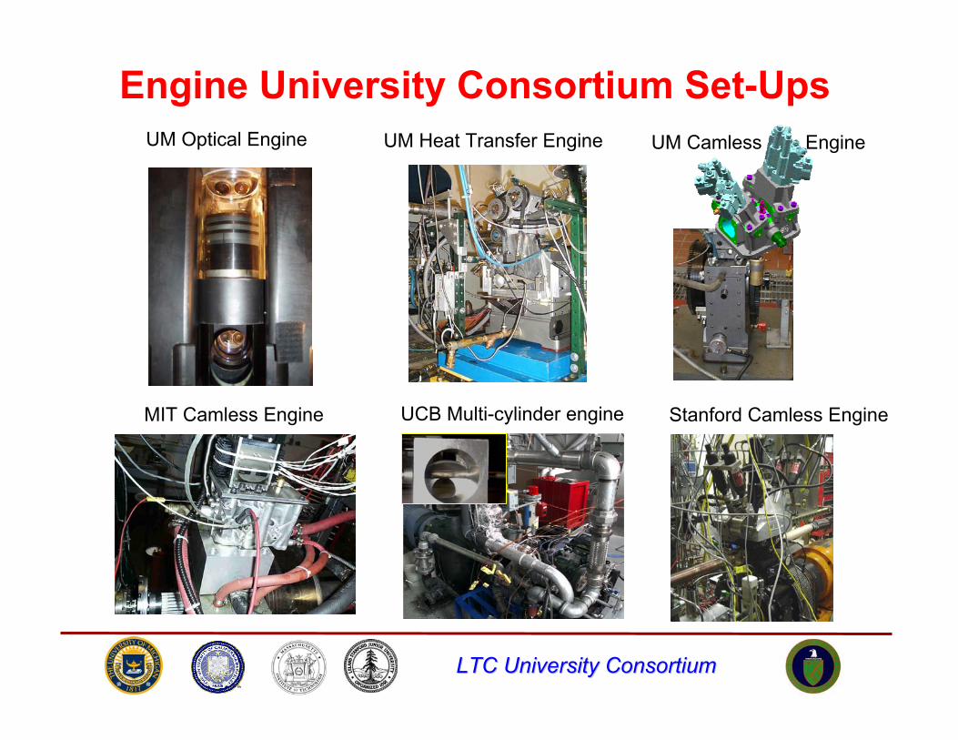
UM Optical Engine UM Heat Transfer Engine
Stanford Camless EngineMIT Camless Engine UCB Multi-cylinder engine
Engine University Consortium Set-UpsUM Camless Engine
LTC University ConsortiumLTC University Consortium
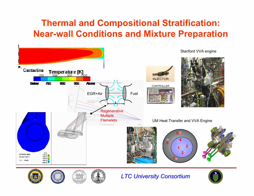
PPCI combustion regime in (Z, η ) plane
0
0.2
0.4
0.6
0.8
1
1.2
0 0.2 0.4 0.6 0.8 1Z (mixture fraction)
J (E
GR
frac
tion)
(i-1)-th flameleti-th flamelet(i+1)-th flamelet
OXIDIZER
η
FUEL
Upper bound of initial η distribution
Lower bound of initial η distribution
EGR
Thermal and Compositional Stratification:Near-wall Conditions and Mixture Preparation
Stanford VVA engine
INJECTOR
CONTROLLER
1 23
4
7
5
61 2
3
4
7
5
6
UM Heat Transfer and VVA Engine
ReactantsEGR
L
ReactantsEGR
L
EGR
L
EGR+Air Fuel
RegenerativeMultipleFlamelets
LTC University ConsortiumLTC University Consortium
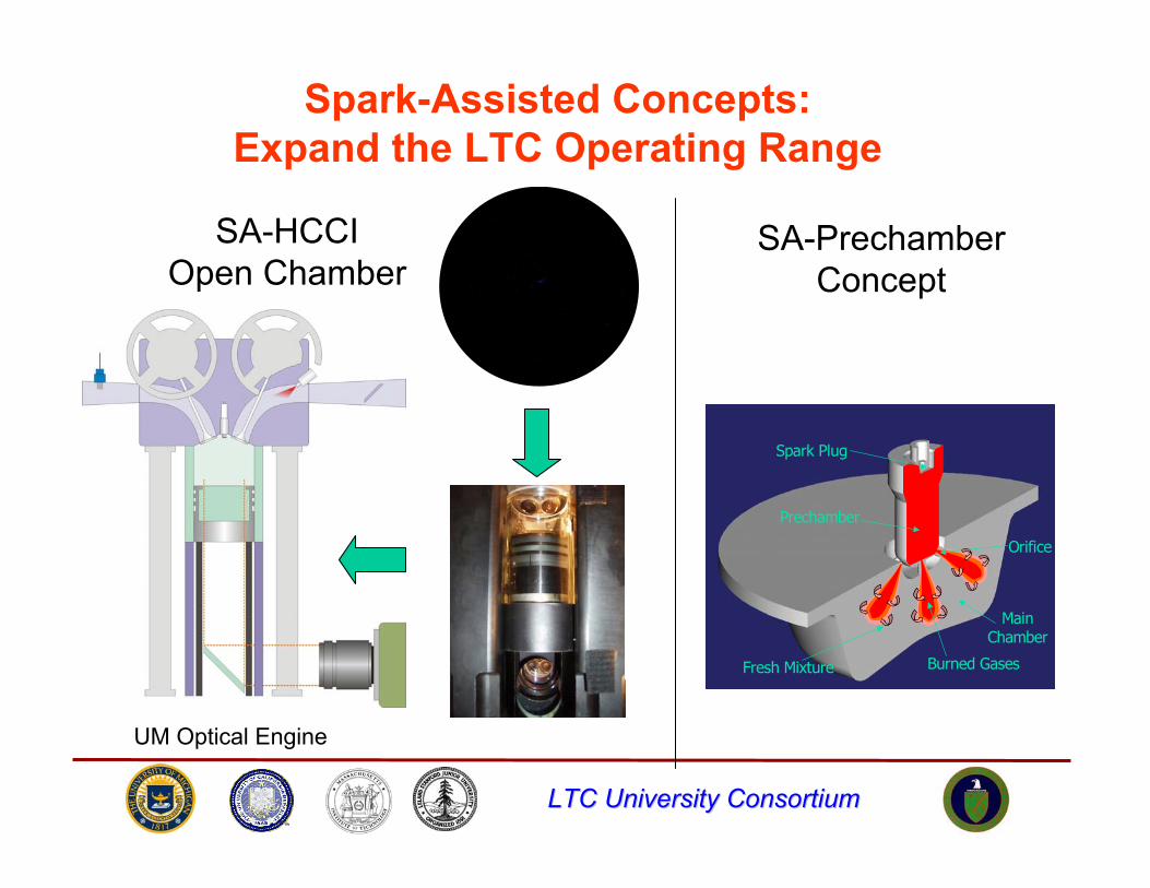
Spark-Assisted Concepts:Expand the LTC Operating Range
Spark Plug
Prechamber
Orifice
Main Chamber
Burned GasesFresh Mixture
Spark Plug
Prechamber
Orifice
Main Chamber
Burned GasesFresh Mixture
SA-HCCIOpen Chamber
SA-PrechamberConcept
UM Optical Engine
LTC University ConsortiumLTC University Consortium
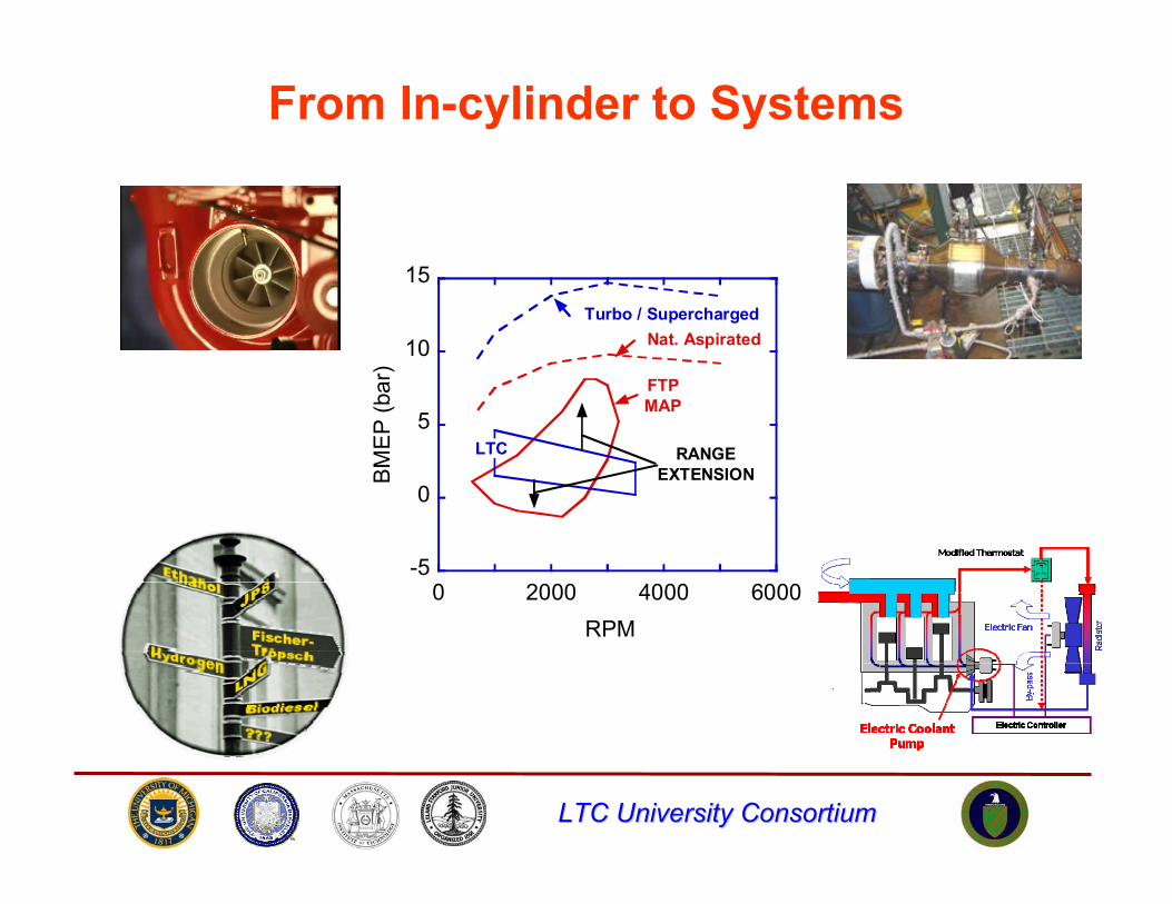
From In-cylinder to Systems
-5
0
5
10
15
0 2000 4000 6000
BM
EP
(bar
)
RPM
LTC
Nat. AspiratedTurbo / Supercharged
FTPMAP
RANGEEXTENSION
LTC University ConsortiumLTC University Consortium
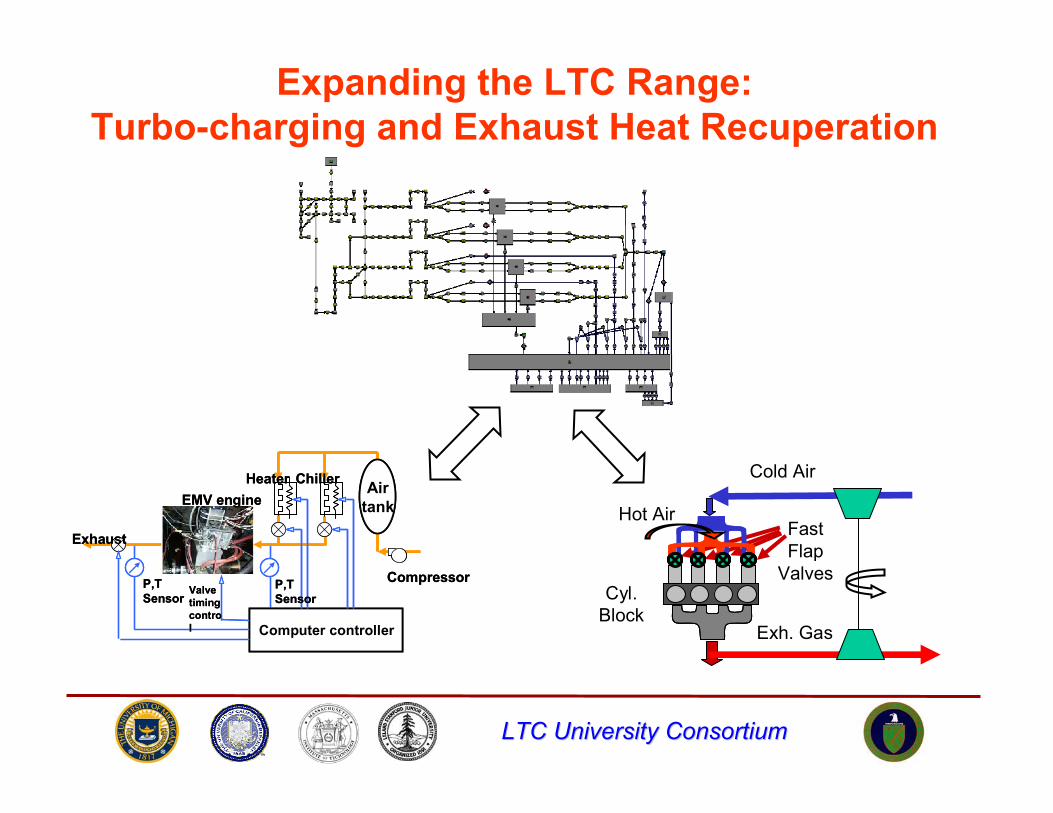
Expanding the LTC Range:Turbo-charging and Exhaust Heat Recuperation
Computer controller
Airtank
Compressor
Heater Chiller
P,TSensor
P,TSensor
Exhaust
EMV engine
Valve timing control Computer controller
Airtank
Compressor
Heater Chiller
P,TSensor
P,TSensor
Exhaust
EMV engine
Valve timing control Exh. Gas
Hot Air
Cyl.Block
FastFlap
Valves
Cold Air
LTC University ConsortiumLTC University Consortium
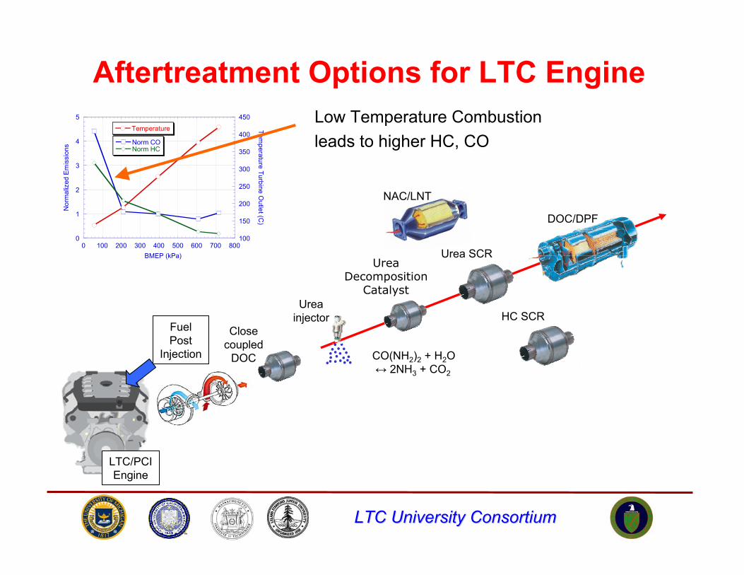
Aftertreatment Options for LTC Engine
0
1
2
3
4
5
100
150
200
250
300
350
400
450
0 100 200 300 400 500 600 700 800
Norm CONorm HC
Temperature
Nor
mal
ized
Em
issi
ons
Temperature Turbine O
utlet (C)
BMEP (kPa)
Closecoupled
DOC
LTC/PCIEngine
DOC/DPF
UreaDecomposition
Catalyst
CO(NH2)2 + H2O↔ 2NH3 + CO2
Urea SCR
Ureainjector
FuelPost
Injection
HC SCR
NAC/LNT
Low Temperature Combustionleads to higher HC, CO
LTC University ConsortiumLTC University Consortium
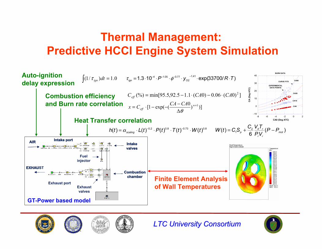
Thermal Management:Predictive HCCI Engine System Simulation
-10
0
10
20
30
40
-8 -6 -4 -2 0 2
BURN DATA
CA
(Deg
ATC
)
CA0 (Deg ATC)
EXPERIMENTALDATA POINTS
CURVE FITS
CA0
CA10
CA50
CA90
Intake port
Fuelinjector
Intakevalves
Exhaustvalves
Exhaust port
Combustionchamber
AIR
EXHAUST
Intake port
Fuelinjector
Intakevalves
Exhaustvalves
Exhaust port
Combustionchamber
AIR
EXHAUST
Auto-ignition delay expression
)/33700exp(103.1 41.12
77.005.14 TRyP Oign ⋅⋅⋅⋅⋅⋅= −−−− φτ0.1)/1( =∫ dtignτ
])0(06.0)0(1.15.92,5.95min[(%) 2CACACeff ⋅−⋅−=
)])0(exp(1[ 1+
Δ−−−⋅= w
effCACACxθ
GT-Power based model
8.073.08.02.0 )()()()()( tWtTtPtLth scaling ⋅⋅⋅⋅= −−α )(6
)( 21 mot
rr
rdp PP
VPTVCSCtW −+=
Combustion efficiency and Burn rate correlation
Heat Transfer correlation
Finite Element Analysis of Wall Temperatures
LTC University ConsortiumLTC University Consortium
400
410
420
430
440
450
460
470
0 20 40 60
Time[sec]
Wal
l tem
pera
ture
[K]
0
1
2
3
4
5
6
7
8
BM
EP [b
ar]
Twall
BMEP
Point4
Point3
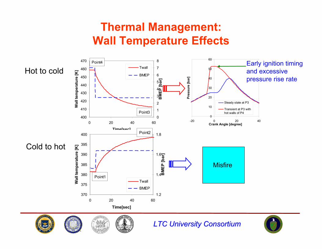
Thermal Management:Wall Temperature Effects
0
10
20
30
40
50
60
-20 0 20 40Crank Angle [degree]
Pres
sure
[bar
]
Steady state at P3
Transient at P3 withhot walls of P4
370
375
380
385
390
395
400
0 20 40 60
Time[sec]
Wal
l tem
pera
ture
[K]
1.2
1.4
1.6
1.8
BM
EP [b
ar]
Twall
BMEP
Point2
Point1
Early ignition timing and excessive pressure rise rate
Hot to cold
Cold to hot
Misfire
LTC University ConsortiumLTC University Consortium
0
1
2
3
4
5
0 1000 2000 3000 4000
RPM
BM
EP
[bar
]
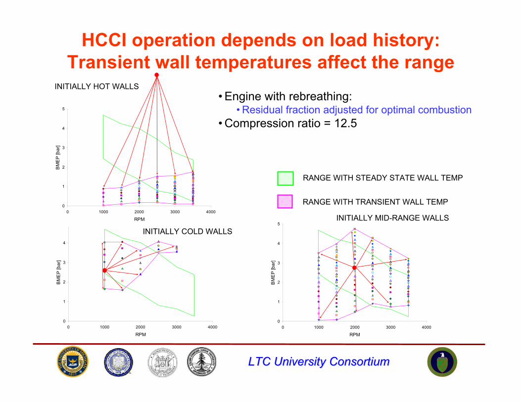
HCCI operation depends on load history:Transient wall temperatures affect the range
0
1
2
3
4
5
0 1000 2000 3000 4000
RPM
BM
EP
[bar
]
RANGE WITH STEADY STATE WALL TEMP
RANGE WITH TRANSIENT WALL TEMP
INITIALLY COLD WALLS
INITIALLY HOT WALLS
0
1
2
3
4
5
0 1000 2000 3000 4000
RPM
BM
EP
[bar
]
INITIALLY MID-RANGE WALLS
• Engine with rebreathing:• Residual fraction adjusted for optimal combustion
• Compression ratio = 12.5
LTC University ConsortiumLTC University Consortium
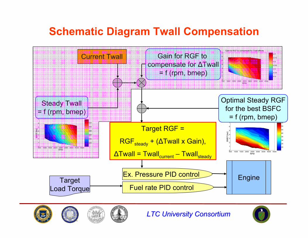
Target RGF =
RGFsteady + (ΔTwall x Gain),
ΔTwall = Twallcurrent – Twallsteady
RPM
BM
EP
[bar
]
Gain for RGF to compensate for Twall effects
500 1000 1500 2000 2500 3000 3500 4000 45000
1
2
3
4
5
6
7
-0.4
-0.35
-0.3
-0.25
-0.2
-0.15
-0.1
RPM
BM
EP
[bar
]
Contour of Residual Gas Fraction [%]
500 1000 1500 2000 2500 3000 3500 4000 45000
1
2
3
4
5
6
7
20
25
30
35
40
45
50
55
RPM
BM
EP
[bar
]
Contour of Piston Surface Temperatures [K]
500 1000 1500 2000 2500 3000 3500 4000 45000
1
2
3
4
5
6
7
420
440
460
480
500
520
Current Twall Gain for RGF to compensate for ΔTwall
= f (rpm, bmep)
Steady Twall= f (rpm, bmep)
Optimal Steady RGFfor the best BSFC= f (rpm, bmep)
EngineEx. Pressure PID control
Fuel rate PID controlTarget
Load Torque
Schematic Diagram Twall Compensation
LTC University ConsortiumLTC University Consortium
BSFC
210
220
230
240
250
260
270
5 10 15 20 25 30 35
Time [sec]
bsfc
[g/k
W.h
]
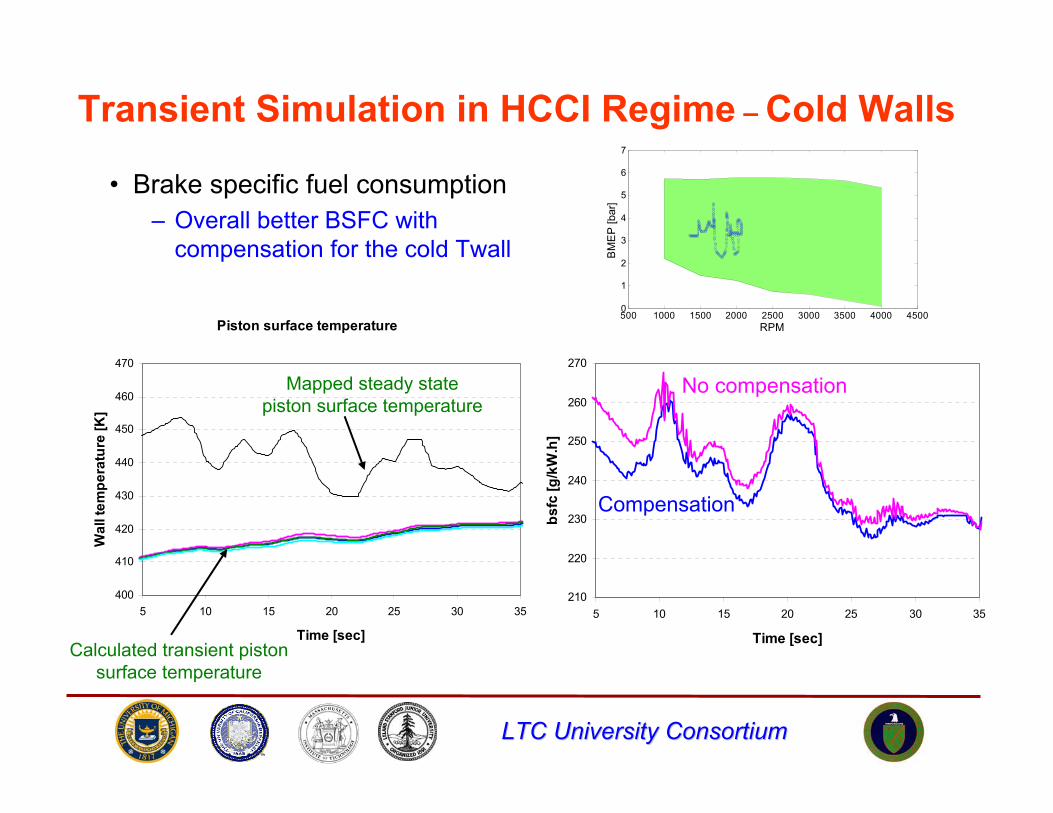
Transient Simulation in HCCI Regime – Cold Walls
• Brake specific fuel consumption– Overall better BSFC with
compensation for the cold Twall
Compensation
Piston surface temperature
400
410
420
430
440
450
460
470
5 10 15 20 25 30 35
Time [sec]
Wal
l tem
pera
ture
[K]
Mapped steady state piston surface temperature
Calculated transient piston surface temperature
No compensation
RPM
BM
EP
[bar
]
500 1000 1500 2000 2500 3000 3500 4000 45000
1
2
3
4
5
6
7
LTC University ConsortiumLTC University Consortium
Acknowledgements• University of Michigan
Dr. Aris Babajimopoulos, Dr. George Lavoie, Dr. Zoran Filipi, Prof. Margaret Wooldridge, Dr. Chris Depcik,Brad Zigler, Jason Martz, Orgun Guralp, Mark Hoffman, Kyoung-Joon Chang, Yanbin Mo, Alex Knafl
• General Motors Research LaboratoriesRod Rask, Paul Najt, Tang Wei Kuo, Pat Szymkowicz
• Lawrence Livermore National LaboratoriesSalvador Aceves, Dan Flowers
• Sandia National LaboratoriesJohn Dec, Magnus Sjoberg
LTC University ConsortiumLTC University Consortium
Thank you!