Embed Size (px)
Citation preview
PropulsionCrafted with craftsman marine
CM2.16 & CM3.27Engine manual

2 Crafted with CRAFTSMAN MARINE
3Crafted with CRAFTSMAN MARINE
This manual applies to model CM2.16 and model CM3.27. Therefore, it can happen that a drawing or picture is not always an exact referral to the engine that you have purchased. Please read this manual carefully before commissioning the engine. Improper use of this engine may cause accidents and all warranty conditions may become invalid.
In this manual you will also find detailed instructions of how and how regularly the various components of your engine must be serviced. This engine must be used exclusively in accordance with the prescription given in the General Conditions of Sale and Supply.
In the case of deviating use the manufacturer does not accept any responsibility whatsoever for resulting damage. This type of risk is to be borne exclusively by the user.
Correct and proper use also implies strictly adhering to the prescriptions of operation, maintenance and repair. Only such persons, who are acquainted with the operation, the maintenance and the repair of your engine, and who are fully aware of any danger involved, should be allowed to work at your engine.
Note:
For that reason, always have your engine serviced, maintained and repaired by an authorized CRAFTSMAN MARINE dealer.
In the case of modifications of the engine, which have not been previously approved by Craftsman Marine in writing, the responsibility of the manufacturer for any resulting damage is immediately rendered null and void.
Modifications of the injection and distribution system also form part of the aforemen-tioned exclusion of the manufacturer’s warranty.
Moreover, they may affect the performance of the engine and the exhaust gas emission in a negative fashion. It may be possible that the fulfillment of the legal prescriptions regarding the emission of exhaust gases, aiming at the protection of the environment, is no longer guaranteed in that case.
Disclaimer
The specifications and the descriptions in this instruction manual were correct at the time of going to press. However, Craftsman Marine is continuously striving after the improvement of its products and therefore reserves the right to modify – at all times and without prior notification - product specifications and instruction manuals.
4 Crafted with CRAFTSMAN MARINE
Preface
Dear owner of this engine,
We should like to thank you very much indeed for your decision to procure a marine diesel engine, made by Craftsman Marine.
Provided you will make proper use of it and take care of adequate maintenance, this engine will serve you faithfully and trouble-free, for many years to come.
This instruction manual informs you about the control, the maintenance and the inspection of the Craftsman Marine diesel engines, models CM2.16 and CM3.27.
Please store this manual in an accessible place.
Should you have any further questions after having read this manual, we shall be delighted to be of service.
Craftsman Marine B.V.
This page will provide you with a survey of all warning pictograms, used throughout this manual. Notes referring to safety issues show this symbol:
Please adhere strictly to the recommendations in this chapter and instruct anybody else, who may be operating or servicing the engine, to do likewise. hese are the safety recommendations:
• Never touch any moving parts when the engine is running.• When in operation the engine (or certain parts thereof) may become very hot. Do
not ever touch these parts and be very careful with flammable products in the neighbourhood of the engine.
• When checking upon or adjusting any parts, or when checking or filling lubricants or cooling liquids, make sure that the engine is stopped.
• Do not open the filler cap on the expansion tank or on the heat exchanger unless the engine is completely cooled down.
• Maintenance and service to the engine must only be provided by experienced people, using suitable tools. If possible entrust only an authorized Craftsman Marine dealer to do such work.
(especially with a view to a safety risk for man or material)
Safety
DANGERATTENTION
Pay attention to the symbols and read the instructions in the text.
Attention
5Crafted with CRAFTSMAN MARINE
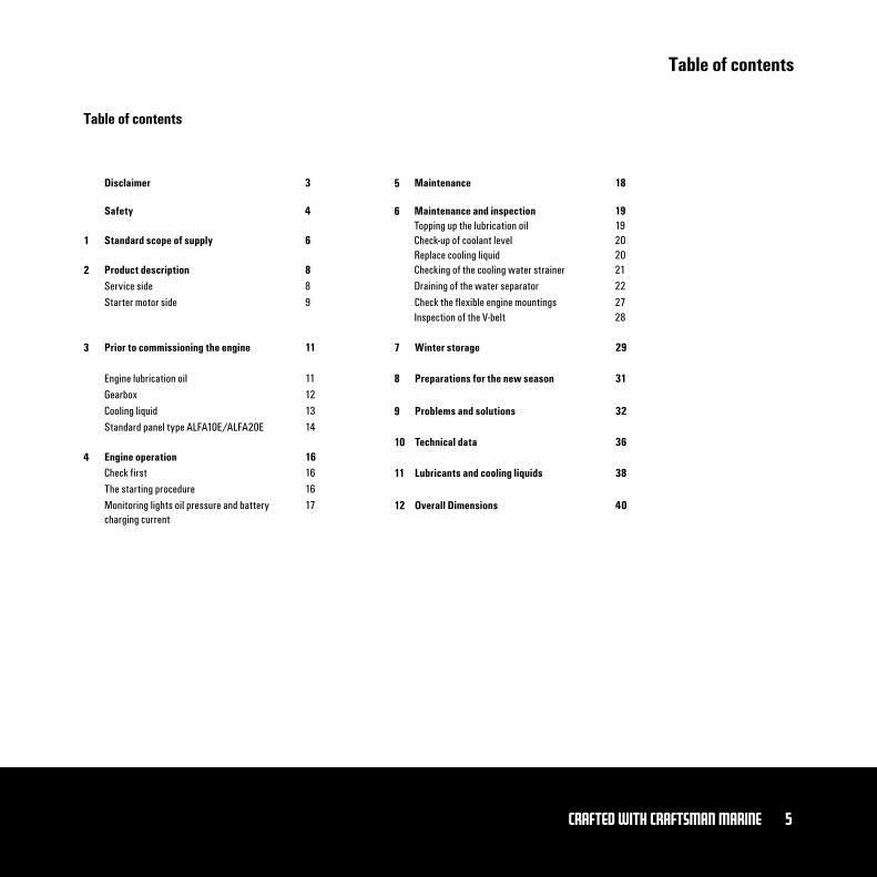
Table of contents
Table of contents
Disclaimer 5
7
8
9
10
11
12
6
1
2
3
4
Safety
Standard scope of supply
Product descriptionService sideStarter motor side
Prior to commissioning the engine
Maintenance
Maintenance and inspection
Inspection of the V-belt
Winter storage
Preparations for the new season
Problems and solutions
Technical data
Lubricants and cooling liquids
Overall Dimensions
Topping up the lubrication oilCheck-up of coolant levelReplace cooling liquidChecking of the cooling water strainerDraining of the water separator
Engine operation
Engine lubrication oilGearboxCooling liquidStandard panel type ALFA10E/ALFA20E
Check firstThe starting procedureMonitoring lights oil pressure and battery charging current
3
4
6
889
11
18
19
28
29
31
32
36
38
40
1920202122
16
11121314
161617
Check the flexible engine mountings 27
6 Crafted with CRAFTSMAN MARINE
Standard scope of supply
By carefully adhering to the following recommendations, you will be sure of the best possible conditions to operate your engine, resulting in a long life span, excellent performance and fuel economy.
• Engine instrument panel, type Alfa 10E or type Alfa 20E• Engine cable loom with fuse and multi-plugs• Connection parts for the push-pull cables• Four flexible engine mountings• Sump pump
• Have the maintenance procedures regularly executed, as mentioned in this manual.
• Prior to starting the engine, always verify the correct level of the various fluids.• All year long, use a good quality anti-freeze product, protecting your engine
against corrosion and frost damage. Please see page 43 for the specifications of the cooling liquid.
• Do not ever put the engine into operation without a properly functioning thermostat, so as to avoid overheating of the engine.
• Always use the correct quality of lubricants, as specified on page 13 of this manual.
• Always use good quality diesel fuel, free from water and /or other impurities.• Switch-off the engine immediately if the monitoring light(s) of oil pressure, fresh• water temperature, raw water temperature and/or battery charging control light
up.
• Fuel filter/water separator in the fuel supply line
Accessory equipment, required for a perfect engine installation (optional):
For a complete list of supply take a look at our websitewww.craftsmanmarine.com
General maintenance directives1
7Crafted with CRAFTSMAN MARINE
Notes
8 Crafted with CRAFTSMAN MARINE
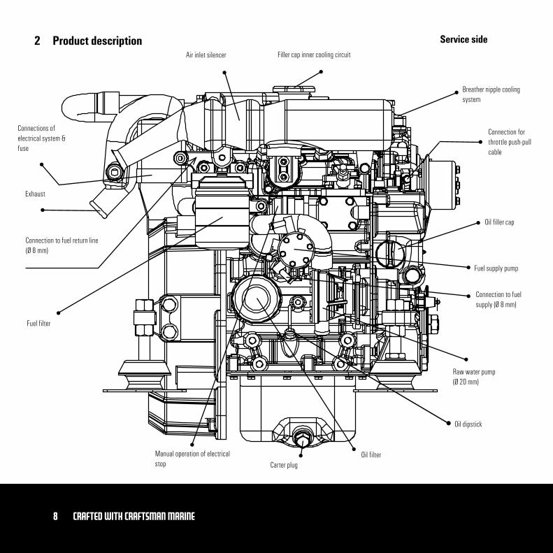
Product description Service side
Oil filler cap
Connection to fuel supply (Ø 8 mm)
Fuel supply pump
Oil dipstick
Oil filter
Fuel filter
Connections of electrical system & fuse
Connection to fuel return line (Ø 8 mm)
Air inlet silencer
Manual operation of electrical stop
Connection for throttle push-pull cable
Breather nipple cooling system
Filler cap inner cooling circuit
Exhaust
Carter plug
Raw water pump (Ø 20 mm)
2
9Crafted with CRAFTSMAN MARINE
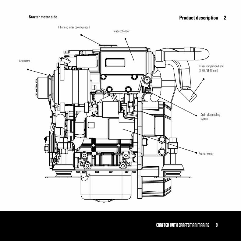
Product descriptionStarter motor side
Filler cap inner cooling circuit
Alternator
Starter motor
Drain plug cooling system
Heat exchanger
Exhaust injection bend (Ø 30 / Ø 40 mm)
2
10 Crafted with CRAFTSMAN MARINE
Product description
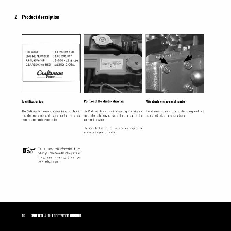
The Craftsman Marine identification tag is the place to find the engine model, the serial number and a few more data concerning your engine.
The Craftsman Marine identification tag is located on top of the rocker cover, next to the filler cap for the inner cooling system.
The identification tag of the 2-cilindre engines is located on the gearbox housing.
The Mitsubishi engine serial number is engraved into the engine block to the starboard side.
Identification tag Position of the identification tag Mitsubushi engine serial number
You will need this information if and when you have to order spare parts, or if you want to correspond with our service department.
2
11Crafted with CRAFTSMAN MARINE
Prior to commissioning the engine
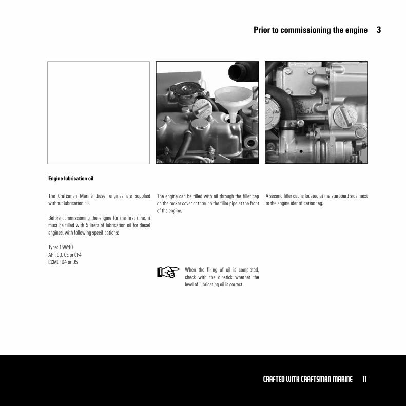
The Craftsman Marine diesel engines are supplied without lubrication oil.
Before commissioning the engine for the first time, it must be filled with 5 liters of lubrication oil for diesel engines, with following specifications:
Type: 15W40API: CD, CE or CF4CCMC: D4 or D5
The engine can be filled with oil through the filler cap on the rocker cover or through the filler pipe at the front of the engine.
A second filler cap is located at the starboard side, next to the engine identification tag.
Engine lubrication oil
When the filling of oil is completed, check with the dipstick whether the level of lubricating oil is correct.
3
12 Crafted with CRAFTSMAN MARINE
Prior to commissioning the engine
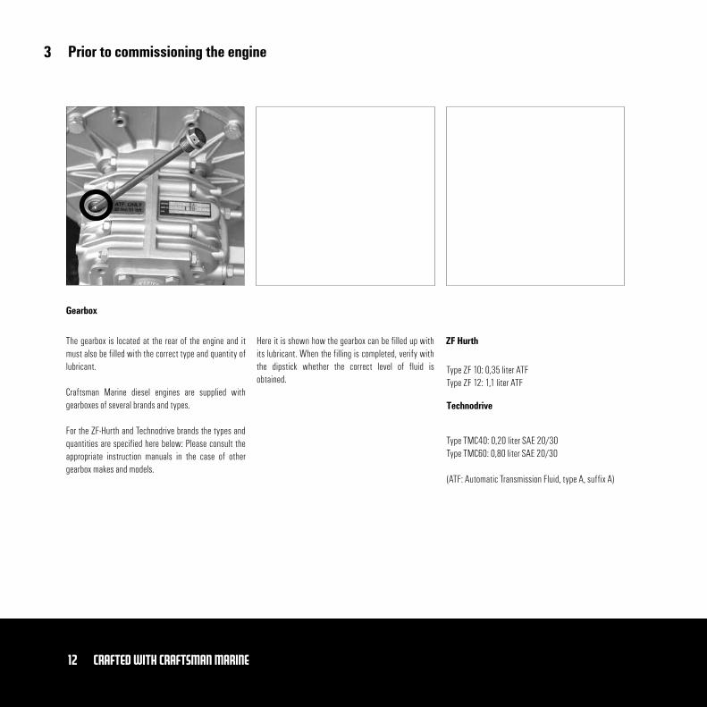
The gearbox is located at the rear of the engine and it must also be filled with the correct type and quantity of lubricant.
Craftsman Marine diesel engines are supplied with gearboxes of several brands and types.
For the ZF-Hurth and Technodrive brands the types and quantities are specified here below: Please consult the appropriate instruction manuals in the case of other gearbox makes and models.
Gearbox
ZF Hurth
Type ZF 10: 0,35 liter ATFType ZF 12: 1,1 liter ATF
Technodrive
Type TMC40: 0,20 liter SAE 20/30Type TMC60: 0,80 liter SAE 20/30
(ATF: Automatic Transmission Fluid, type A, suffix A)
Here it is shown how the gearbox can be filled up with its lubricant. When the filling is completed, verify with the dipstick whether the correct level of fluid is obtained.
3
13Crafted with CRAFTSMAN MARINE
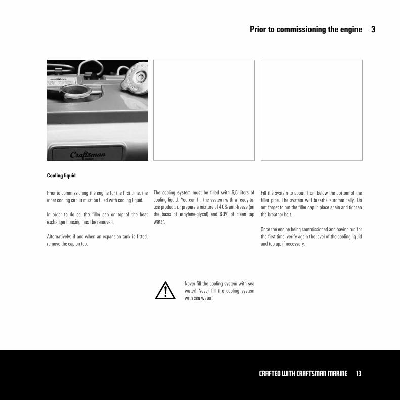
Prior to commissioning the engine
Prior to commissioning the engine for the first time, the inner cooling circuit must be filled with cooling liquid.
In order to do so, the filler cap on top of the heat exchanger housing must be removed.
Alternatively: if and when an expansion tank is fitted, remove the cap on top.
The cooling system must be filled with 6,5 liters of cooling liquid. You can fill the system with a ready-to-use product, or prepare a mixture of 40% anti-freeze (on the basis of ethylene-glycol) and 60% of clean tap water.
Fill the system to about 1 cm below the bottom of the filler pipe. The system will breathe automatically. Do not forget to put the filler cap in place again and tighten the breather bolt.
Once the engine being commissioned and having run for the first time, verify again the level of the cooling liquid and top up, if necessary.
Cooling liquid
Never fill the cooling system with sea water! Never fill the cooling system with sea water!
3
14 Crafted with CRAFTSMAN MARINE
Prior to commissioning the engine
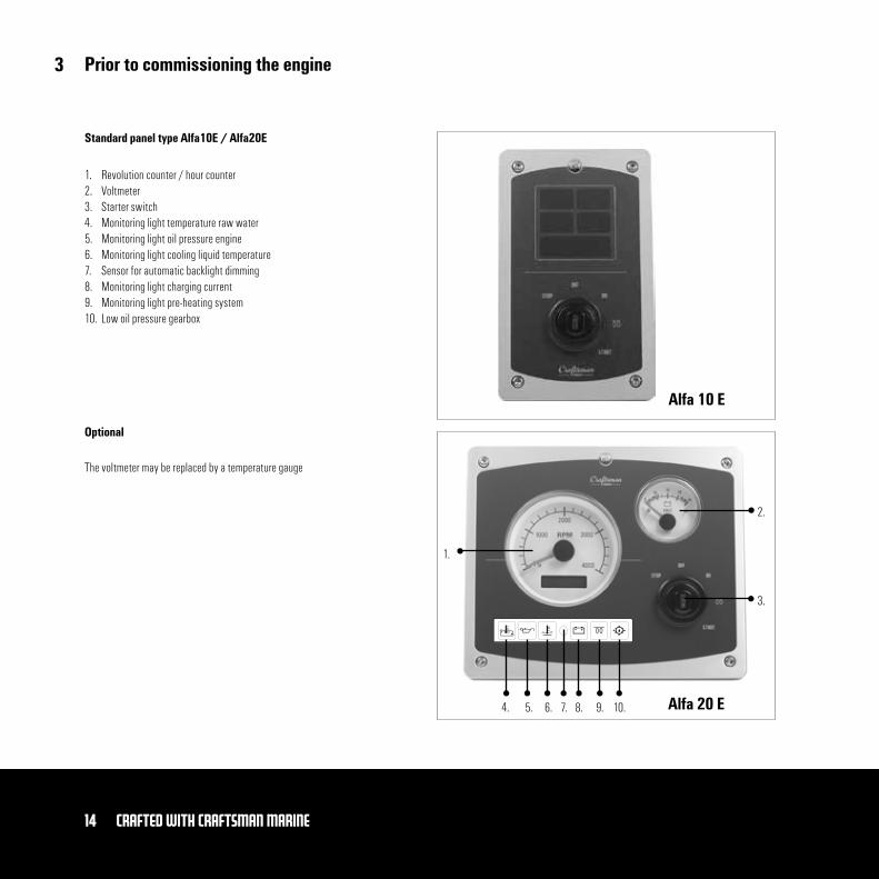
Standard panel type Alfa10E / Alfa20E
1. Revolution counter / hour counter2. Voltmeter3. Starter switch4. Monitoring light temperature raw water5. Monitoring light oil pressure engine6. Monitoring light cooling liquid temperature7. Sensor for automatic backlight dimming 8. Monitoring light charging current9. Monitoring light pre-heating system10. Low oil pressure gearbox
The voltmeter may be replaced by a temperature gauge
Optional
Alfa 10 E
4. 5. 6. 7. 8. 9. 10.
1.
2.
3.
Alfa 20 E
3
15Crafted with CRAFTSMAN MARINE
Prior to commissioning the engine
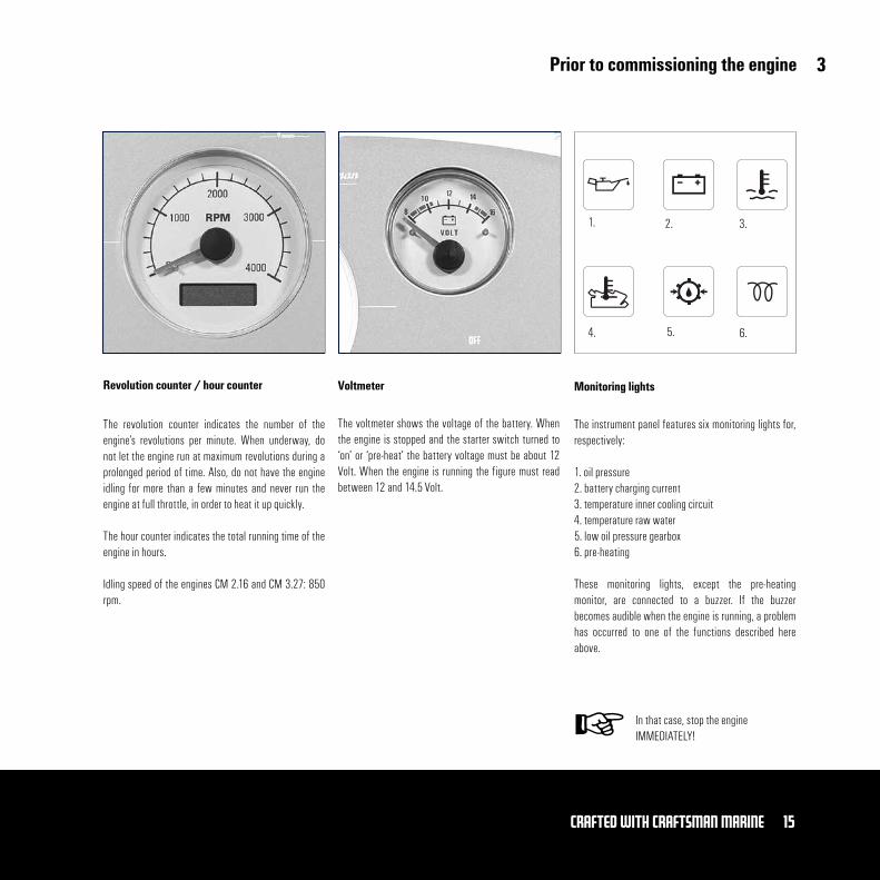
The revolution counter indicates the number of the engine’s revolutions per minute. When underway, do not let the engine run at maximum revolutions during a prolonged period of time. Also, do not have the engine idling for more than a few minutes and never run the engine at full throttle, in order to heat it up quickly.
The hour counter indicates the total running time of the engine in hours.
Idling speed of the engines CM 2.16 and CM 3.27: 850 rpm.
The voltmeter shows the voltage of the battery. When the engine is stopped and the starter switch turned to ‘on’ or ‘pre-heat’ the battery voltage must be about 12 Volt. When the engine is running the figure must read between 12 and 14.5 Volt.
Revolution counter / hour counter Voltmeter Monitoring lights
1. 2. 3.
4. 5. 6.
The instrument panel features six monitoring lights for, respectively:
1. oil pressure2. battery charging current3. temperature inner cooling circuit4. temperature raw water5. low oil pressure gearbox6. pre-heating
These monitoring lights, except the pre-heating monitor, are connected to a buzzer. If the buzzer becomes audible when the engine is running, a problem has occurred to one of the functions described here above.
In that case, stop the engine IMMEDIATELY!
3
16 Crafted with CRAFTSMAN MARINE
Engine operation
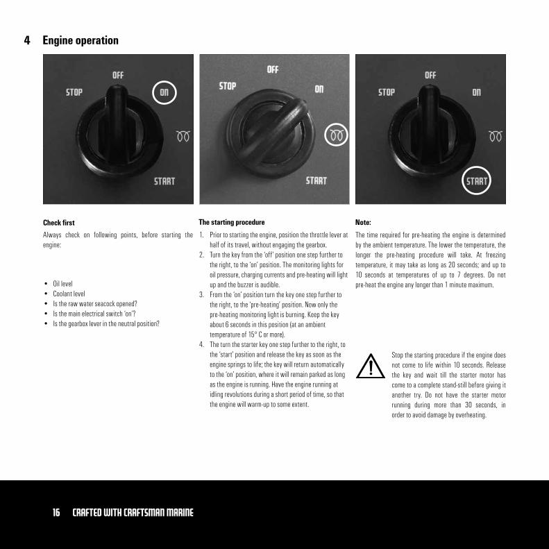
• Oil level• Coolant level • Is the raw water seacock opened?• Is the main electrical switch ‘on’? • Is the gearbox lever in the neutral position?
The time required for pre-heating the engine is determined by the ambient temperature. The lower the temperature, the longer the pre-heating procedure will take. At freezing temperature, it may take as long as 20 seconds; and up to 10 seconds at temperatures of up to 7 degrees. Do not pre-heat the engine any longer than 1 minute maximum.
Check first The starting procedure Note:
Always check on following points, before starting the engine:
1. Prior to starting the engine, position the throttle lever at half of its travel, without engaging the gearbox.
2. Turn the key from the ‘off’ position one step further to the right, to the ‘on’ position. The monitoring lights for oil pressure, charging currents and pre-heating will light up and the buzzer is audible.
3. From the ‘on’ position turn the key one step further to the right, to the ‘pre-heating’ position. Now only the pre-heating monitoring light is burning. Keep the key about 6 seconds in this position (at an ambient temperature of 15° C or more).
4. The turn the starter key one step further to the right, to the ‘start’ position and release the key as soon as the engine springs to life; the key will return automatically to the ‘on’ position, where it will remain parked as long as the engine is running. Have the engine running at idling revolutions during a short period of time, so that the engine will warm-up to some extent.
Stop the starting procedure if the engine does not come to life within 10 seconds. Release the key and wait till the starter motor has come to a complete stand-still before giving it another try. Do not have the starter motor running during more than 30 seconds, in order to avoid damage by overheating.
4
17Crafted with CRAFTSMAN MARINE
Engine operation
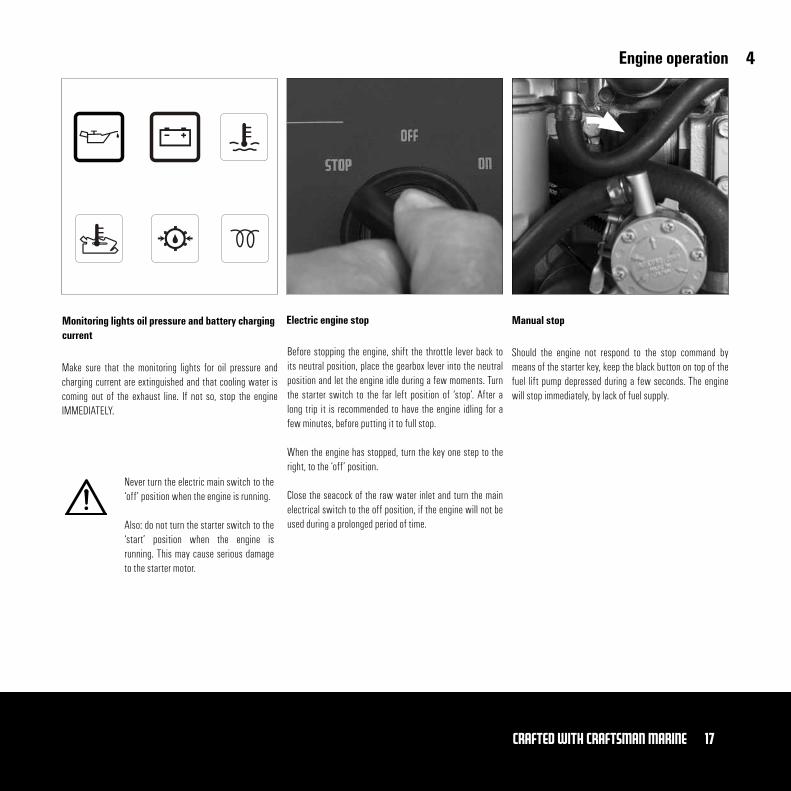
Monitoring lights oil pressure and battery charging current
Electric engine stop Manual stop
Make sure that the monitoring lights for oil pressure and charging current are extinguished and that cooling water is coming out of the exhaust line. If not so, stop the engine IMMEDIATELY.
Before stopping the engine, shift the throttle lever back to its neutral position, place the gearbox lever into the neutral position and let the engine idle during a few moments. Turn the starter switch to the far left position of ‘stop’. After a long trip it is recommended to have the engine idling for a few minutes, before putting it to full stop.
When the engine has stopped, turn the key one step to the right, to the ‘off’ position.
Close the seacock of the raw water inlet and turn the main electrical switch to the off position, if the engine will not be used during a prolonged period of time.
Should the engine not respond to the stop command by means of the starter key, keep the black button on top of the fuel lift pump depressed during a few seconds. The engine will stop immediately, by lack of fuel supply.
Never turn the electric main switch to the ‘off’ position when the engine is running.
Also: do not turn the starter switch to the ‘start’ position when the engine is running. This may cause serious damage to the starter motor.
4
18 Crafted with CRAFTSMAN MARINE
Maintenance
Recording of data for verification
Every 10 hours or daily before starting
After the first 50 hours of operation
After every 100 hours of operation (or at least once a year)
• Check level of engine lubricating oil (page 19)• Check level of cooling liquid (page 20)• Check cooling water strainer for blockage of the water flow (page 21)
Ask your dealer to execute this maintenance job:
Ask your dealer to execute this service job:
• Drain water from the fuel filter/water separator (page 22)• Change engine lubrication oil (page 23)• Replace oil filter (page 23)• Change lubricating fluid in gearbox (page 25)• Replace fuel filter (page 26)• Verify idling revolutions and adjust if necessary (page 15)
• Drain water from the fuel filter/water separator• Change engine lubrication oil• Replace oil filter• Verify level of lubricating fluid in gearbox• Replace fuel filter • Check batteries, cables and connections
In order to ensure a long life span of your engine, it is imperative to adhere to the following directives pertaining to the periodical maintenance of the engine and its compo-nents. In the case of inadequate maintenance, serious damage can be caused to the engine and no warranty claim can be accepted by the manufacturer. These are the jobs to be performed:
After every 500 hours of operation (at least once a year)
Have your dealer check and execute the following:• Verify the tolerance of the valves• Replace the fuel filter• Change the oil in the gearbox• Clean the filter, which is located just before the fuel lift pump• Verify the flexible engine mountings to have the correct compression and adjust
if necessary• Check all hoses and hose connections for leaks• Verify the tension of the V-belt
After every 1000 hours of operation (or at least once every two years)
Have your dealer check and execute the following:• Verify the proper functioning of the raw water pump• Replace the cooling liquid in the inner cooling circuit
If necessary: - Bleed the fuel system (page 22) - Verify the number of revolutions when idling (page 15)
Only service the engine when it is not running!
5
19Crafted with CRAFTSMAN MARINE
Maintenance and inspection
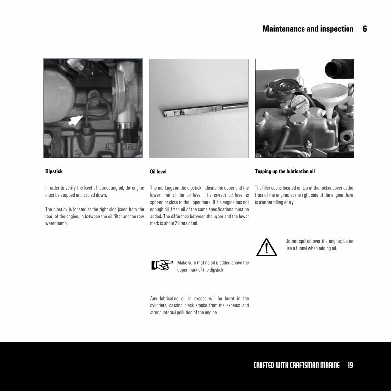
In order to verify the level of lubricating oil, the engine must be stopped and cooled down.
The dipstick is located at the right side (seen from the rear) of the engine, in between the oil filter and the raw water pump.
The markings on the dipstick indicate the upper and the lower limit of the oil level. The correct oil level is spot-on or close to the upper mark. If the engine has not enough oil, fresh oil of the same specifications must be added. The difference between the upper and the lower mark is about 2 liters of oil.
Any lubricating oil in excess will be burnt in the cylinders, causing black smoke from the exhaust and strong internal pollution of the engine.
Dipstick Oil level Topping up the lubrication oil
The filler cap is located on top of the rocker cover at the front of the engine; at the right side of the engine there is another filling entry.
Do not spill oil over the engine; better use a funnel when adding oil.
Make sure that no oil is added above the upper mark of the dipstick.
6

20 Crafted with CRAFTSMAN MARINE
Maintenance and inspection
Always verify the level of the cooling fluid when the engine is cold. Open the filler cap on the expansion tank (if fitted) or else the filler cap on top of the housing of the heat exchanger and make sure that the coolant is level is about 1 cm below the bottom of the filler pipe.
If so required, top up with fresh cooling liquid (see page 39)
Remove the two drain plugs of the cooling system from the engine block (1) and the housing of the heat exchanger (2). Remove the filler cap from the expansion tank (and/or the heat exchanger housing), in order to quickly drain the liquid from the internal cooling circuit and to make sure that all of the liquid has been discharged from the engine.
Replace the drain plugs and tighten them well. The inner cooling circuit is filled through the filler cap on top of the heat exchanger housing or, as the case may be, of the expansion tank.
Before filling in the fresh coolant, remove as well the bolt on top of the cover of the thermostat housing. This enables the cooling system to be vented (air-bled).
Check-up of coolant level Replace cooling liquid
Fill the system with a mixture of 40% of anti-freeze and 60% of clean tap water.
You may also use ready-made cooling liquid; see page 43 for the relevant specifications of the recommended coolant.
Top up to a level of about 1 cm below the bottom of the filler pipe. After the engine being commissioned for the first time, i.e. has warmed-up and cooled down completely thereafter, check again the coolant level and top up if necessary.
Never add sea (or salt) water into the inner cooling circuit!
1. 2.
Open the filler cap on top of the heat exchanger housing only when the engine is cold.
6

21Crafted with CRAFTSMAN MARINE
Maintenance and inspection
Each day, prior to starting the engine, make sure that the cooling water strainer is not clogged by dirt. Close the raw water seacock and remove the cover from the filter housing for proper inspection.
Clean the filter element at least twice a year, or whenever necessary. If the cooling water strainer gets clogged up, the cooling liquid in the engine may overheat.
When closing the strainer gain, make sure that the cover is perfectly shutting the unit off. If and when air is sucked into the system, on account of a badly closing filter cover, there is a severe risk of overheating of the engine.
Checking of the cooling water strainer Cleaning of the cooling water strainer Check once again!
Make absolutely sure that the cover fits the strainer housing well and without any air leaks!
6
22 Crafted with CRAFTSMAN MARINE
Maintenance and inspection
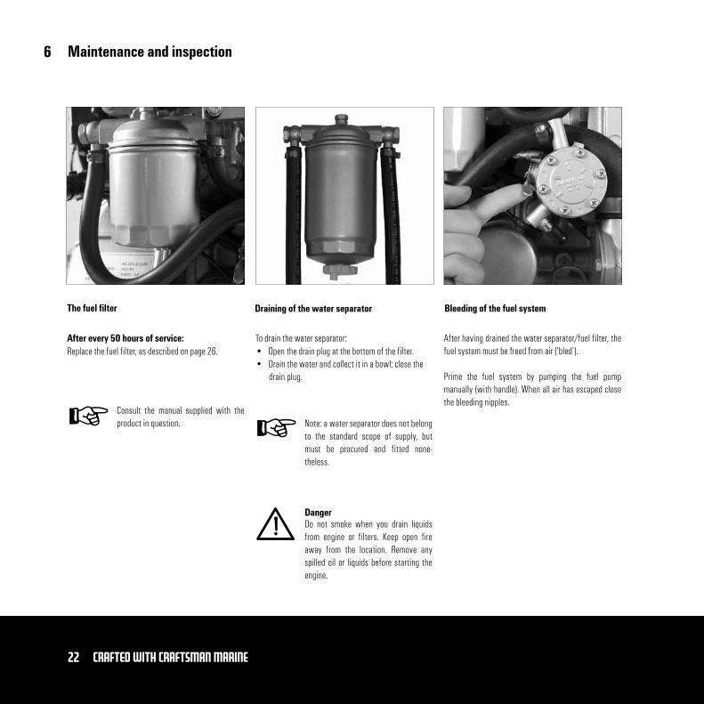
After every 50 hours of service:Replace the fuel filter, as described on page 26.
To drain the water separator:• Open the drain plug at the bottom of the filter.• Drain the water and collect it in a bowl; close the
drain plug.
The fuel filter Draining of the water separator Bleeding of the fuel system
After having drained the water separator/fuel filter, the fuel system must be freed from air (‘bled’). Prime the fuel system by pumping the fuel pump manually (with handle). When all air has escaped close the bleeding nipples.
Danger
Note: a water separator does not belong to the standard scope of supply, but must be procured and fitted none-theless.
Do not smoke when you drain liquids from engine or filters. Keep open fire away from the location. Remove any spilled oil or liquids before starting the engine.
Consult the manual supplied with the product in question.
6
23Crafted with CRAFTSMAN MARINE
Maintenance and inspection
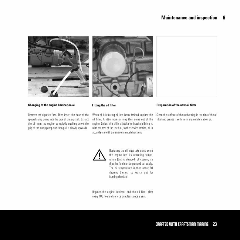
Remove the dipstick first. Then insert the hose of the special sump pump into the pipe of the dipstick. Extract the oil from the engine by quickly pushing down the grip of the sump pump and then pull it slowly upwards.
When all lubricating oil has been drained, replace the oil filter. A little more oil may then come out of the engine. Collect this oil in a beaker or bowl and bring it, with the rest of the used oil, to the service station, all in accordance with the environmental directives.
Replace the engine lubricant and the oil filter after every 100 hours of service or at least once a year.
Changing of the engine lubrication oil Fitting the oil filter Preparation of the new oil filter
Clean the surface of the rubber ring in the rim of the oil filter and grease it with fresh engine lubrication oil.
Replacing the oil must take place when the engine has its operating tempe-rature (but is stopped, of course), so that the fluid can be pumped out easily. The oil temperature is then about 80 degrees Celsius, so watch out for burning the skin!
6
24 Crafted with CRAFTSMAN MARINE
Maintenance and inspection
Turn the new oil filter onto the engine, thereby following the instructions given on the filter housing.
Fill the engine with lubrication oil with specifications as outlined on page 11 through one of both filling entries.
Use a funnel in order to avoid spilling of oil over the engine. Have the engine idling during a few moments and check after leaks.
Stop the engine and check the oil level by means of the dipstick, after about 5 minutes’ time.
Positioning of the oil filter Adding new oil filter
6
25Crafted with CRAFTSMAN MARINE
Maintenance and inspection
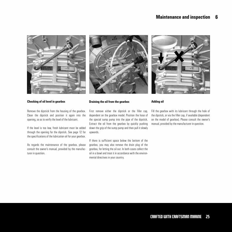
Remove the dipstick from the housing of the gearbox. Clean the dipstick and position it again into the opening, so as to verify the level of the lubricant.
If the level is too low, fresh lubricant must be added through the opening for the dipstick. See page 12 for the specifications of the lubrication oil for your gearbox.
As regards the maintenance of the gearbox, please consult the owner’s manual, provided by the manufac-turer in question.
First remove either the dipstick or the filler cap, dependent on the gearbox model. Position the hose of the special sump pump into the pipe of the dipstick. Extract the oil from the gearbox by quickly pushing down the grip of the sump pump and then pull it slowly upwards.
If there is sufficient space below the bottom of the gearbox, you may also remove the drain plug of the gearbox, for letting the oil out. In both cases collect the oil in a bowl and treat it in accordance with the environ-mental directives in your country.
Checking of oil level in gearbox Draining the oil from the gearbox Adding oil
Fill the gearbox with its lubricant through the hole of the dipstick, or via the filler cap, if available (dependent on the model of gearbox). Please consult the owner’s manual, provided by the manufacturer in question.
6
26 Crafted with CRAFTSMAN MARINE
Maintenance and inspection
Close-off the fuel supply to the engine. Remove the entire filter with the aid of a special tool. It is possible that the filter still contains some fuel, which please collect and treat it in accordance with the environ-mental directives in your country.
Clean the surface to touch the engine before fitting the filter. Grease the rubber ring with clean engine oil. Fill the filter with clean diesel fuel. Position the filter against the filter housing and tighten it with one half to three quarters of a turn.
Clean the filter of the fuel lift pump and reopen the cock of the fuel supply.
Remove the fuel filter Fit the fuel filter Cleaning the filter of the fuel lift pump
Consult your dealer.
Do not smoke when working at or around the fuel system and avoid open fire.
6
27Crafted with CRAFTSMAN MARINE
Maintenance and inspection
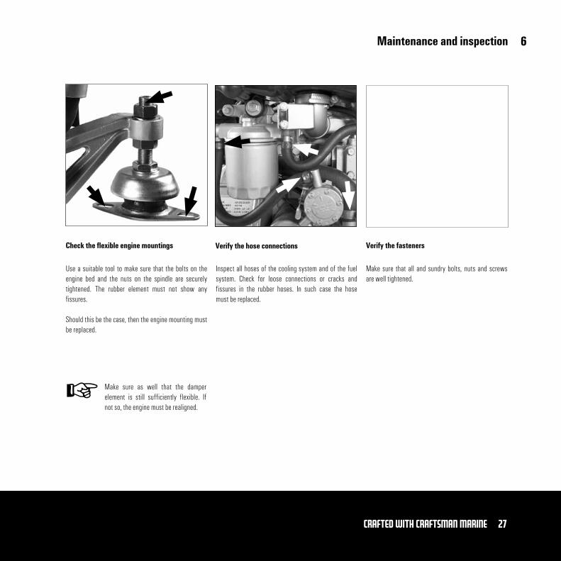
Use a suitable tool to make sure that the bolts on the engine bed and the nuts on the spindle are securely tightened. The rubber element must not show any fissures.
Should this be the case, then the engine mounting must be replaced.
Inspect all hoses of the cooling system and of the fuel system. Check for loose connections or cracks and fissures in the rubber hoses. In such case the hose must be replaced.
Check the flexible engine mountings Verify the hose connections Verify the fasteners
Make sure that all and sundry bolts, nuts and screws are well tightened.
Make sure as well that the damper element is still sufficiently flexible. If not so, the engine must be realigned.
6
28 Crafted with CRAFTSMAN MARINE
Maintenance and inspection
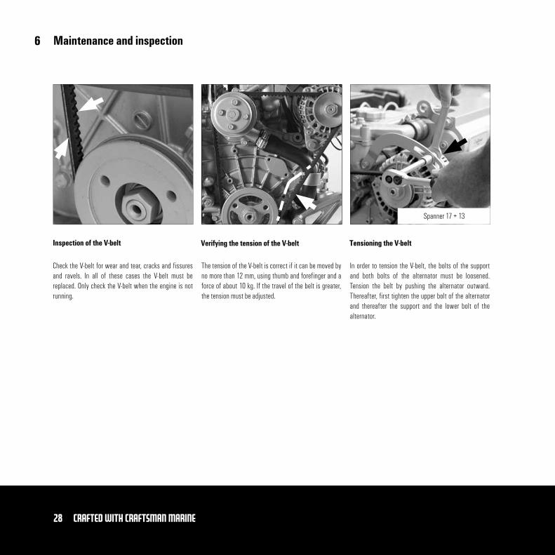
Check the V-belt for wear and tear, cracks and fissures and ravels. In all of these cases the V-belt must be replaced. Only check the V-belt when the engine is not running.
The tension of the V-belt is correct if it can be moved by no more than 12 mm, using thumb and forefinger and a force of about 10 kg. If the travel of the belt is greater, the tension must be adjusted.
Inspection of the V-belt Verifying the tension of the V-belt Tensioning the V-belt
In order to tension the V-belt, the bolts of the support and both bolts of the alternator must be loosened. Tension the belt by pushing the alternator outward. Thereafter, first tighten the upper bolt of the alternator and thereafter the support and the lower bolt of the alternator.
Spanner 17 + 13
6
29Crafted with CRAFTSMAN MARINE
Winter storage
So as to protect your engine well during the standstill of the winter season, it is recommended to have the engine running for some 10 minutes with a protective mixture of 10% lubrication oil and 90% of clean diesel fuel.
Replace the oil filter and change the engine lubrication oil with a good quality of oil, with protective properties. See page 23.
Protective fuel mixture Lubrication oil system Raw water cooling system
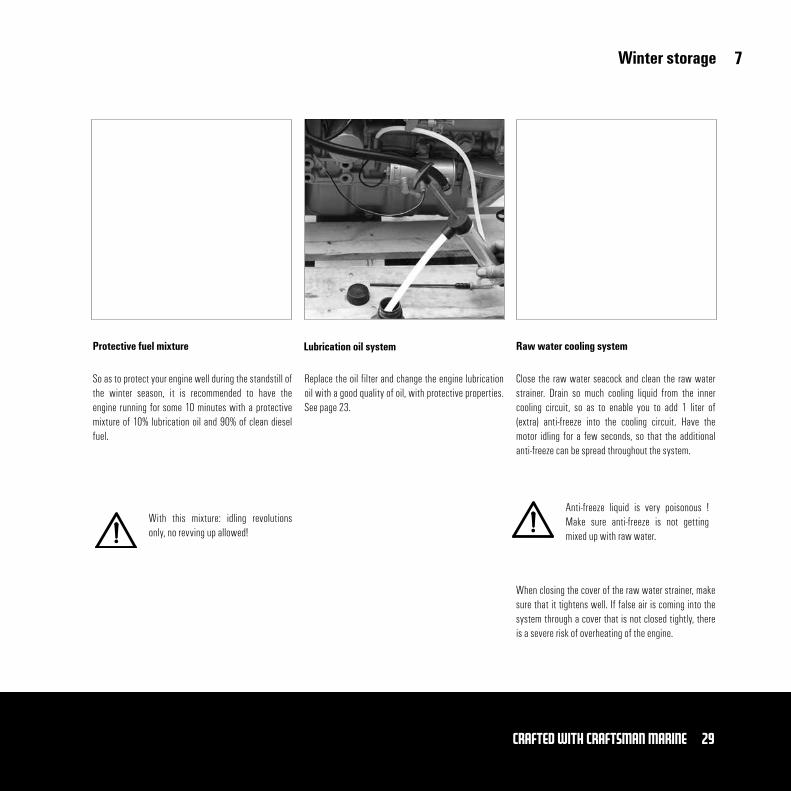
Close the raw water seacock and clean the raw water strainer. Drain so much cooling liquid from the inner cooling circuit, so as to enable you to add 1 liter of (extra) anti-freeze into the cooling circuit. Have the motor idling for a few seconds, so that the additional anti-freeze can be spread throughout the system.
When closing the cover of the raw water strainer, make sure that it tightens well. If false air is coming into the system through a cover that is not closed tightly, there is a severe risk of overheating of the engine.
With this mixture: idling revolutions only, no revving up allowed!
Anti-freeze liquid is very poisonous ! Make sure anti-freeze is not getting mixed up with raw water.
7
30 Crafted with CRAFTSMAN MARINE
Winter storage
Make sure that the inner cooling system contains suffi-cient anti-freeze, in order to avoid corrosion. Check with the aid of a volume gauge. See page 39 for the relevant specifications. If it appears that there is not enough anti-freeze in the coolant, replace the liquid, as described on page 20.
Disconnect the battery cables and charge the batteries from time to time, during the winter period.
Inner circuit of the cooling system Electrical system Filters
Drain the water from the fuel filter/water separator in order to avoid frost damage.
Fit a new fuel filter, see page 26.
7
31Crafted with CRAFTSMAN MARINE
Preparations for the new season
1. Open the fuel supply cock.
2 Charge the battery (ies), if necessary.
3. Connect the battery cables.
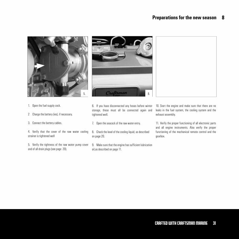
4. Verify that the cover of the raw water cooling strainer is tightened well
5. Verify the tightness of the raw water pump cover and of all drain plugs (see page 20).
6. If you have disconnected any hoses before winter storage, these must all be connected again and tightened well.
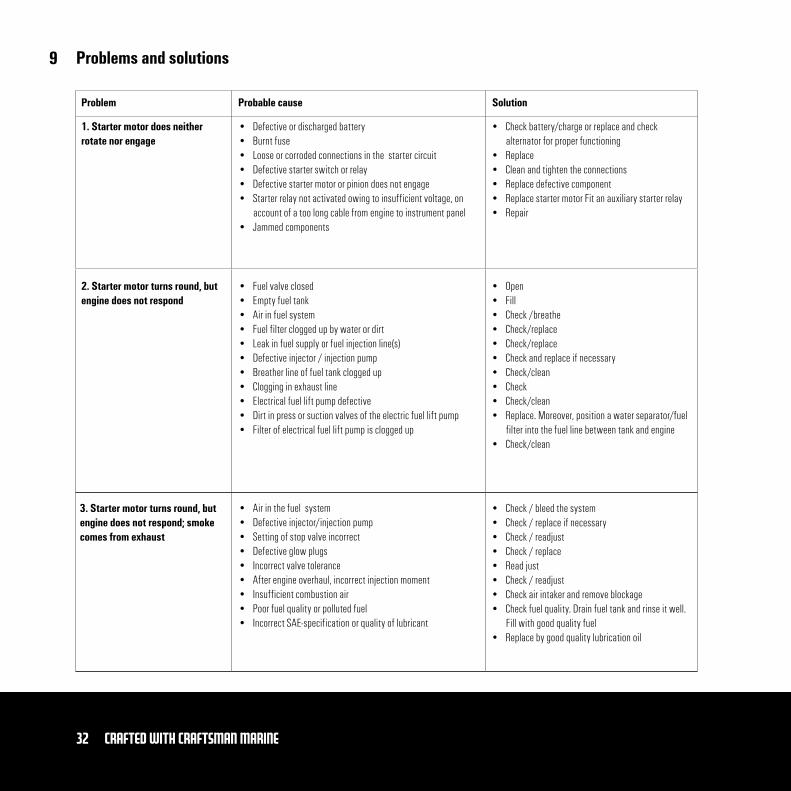
7. Open the seacock of the raw water entry.
8. Check the level of the cooling liquid, as described on page 20.
9. Make sure that the engine has sufficient lubrication oil,as described on page 11.
10. Start the engine and make sure that there are no leaks in the fuel system, the cooling system and the exhaust assembly.
11. Verify the proper functioning of all electronic parts and all engine instruments. Also verify the proper functioning of the mechanical remote control and the gearbox.
8.5.
8
32 Crafted with CRAFTSMAN MARINE
Problems and solutions
Problem
1. Starter motor does neither rotate nor engage
• Defective or discharged battery• Burnt fuse• Loose or corroded connections in the starter circuit• Defective starter switch or relay• Defective starter motor or pinion does not engage• Starter relay not activated owing to insufficient voltage, on
account of a too long cable from engine to instrument panel• Jammed components
• Check battery/charge or replace and check alternator for proper functioning
• Replace• Clean and tighten the connections• Replace defective component• Replace starter motor Fit an auxiliary starter relay• Repair
• Open• Fill• Check /breathe• Check/replace• Check/replace• Check and replace if necessary• Check/clean• Check• Check/clean• Replace. Moreover, position a water separator/fuel
filter into the fuel line between tank and engine• Check/clean
• Check / bleed the system• Check / replace if necessary • Check / readjust• Check / replace• Read just• Check / readjust• Check air intaker and remove blockage• Check fuel quality. Drain fuel tank and rinse it well.
Fill with good quality fuel• Replace by good quality lubrication oil
• Fuel valve closed• Empty fuel tank• Air in fuel system • Fuel filter clogged up by water or dirt• Leak in fuel supply or fuel injection line(s) • Defective injector / injection pump • Breather line of fuel tank clogged up• Clogging in exhaust line • Electrical fuel lift pump defective• Dirt in press or suction valves of the electric fuel lift pump• Filter of electrical fuel lift pump is clogged up
• Air in the fuel system• Defective injector/injection pump• Setting of stop valve incorrect• Defective glow plugs• Incorrect valve tolerance • After engine overhaul, incorrect injection moment • Insufficient combustion air• Poor fuel quality or polluted fuel • Incorrect SAE-specification or quality of lubricant
2. Starter motor turns round, but engine does not respond
3. Starter motor turns round, but engine does not respond; smoke comes from exhaust
Probable cause Solution
9
33Crafted with CRAFTSMAN MARINE
Problems and solutions
Problem Probable cause Solution
4. Engine starts running but with irregular cycles or it stops again
5. Engine does not arrive at maxi-mum revolutions under full load
• Empty fuel tank• Air in the fuel system• Fuel filter clogged up with water and/or dirt• Leaking fuel supply or fuel injection line • Defective injector/injection pump• Breather line of fuel tank clogged up • Fuel line clogged• Incorrect valve clearance• Idling revolutions too low• Exhaust clogged up• Poor fuel quality or polluted fuel• Filter of electrical fuel lift pump is clogged
• Air in the fuel system• Fuel filter clogged up with water and/or dirt • Leakage in fuel supply line or fuel injection line • Setting of stop valve incorrect• Oil level too high• Incorrect SAE-specification or quality of lubrication oil • Incorrect valve clearance • Clogging in the exhaust• Insufficient quantity of combusition air• Poor fuel quality or polluted fuel • Incorrect injection moment• Leakage of air intake manifold • Engine overload
• Fill it• Check / bleed the system• Check / clean or replace • Check and replace, if necessary• Check and clean or replace• Check /remove blockage• Check / remove blockage• Readjust• Readjust• Check / remove blockage• Check fuel quality. Drain fuel tank and rinse it well.
Fill with good quality fuel• Check / clean
• Check and bleed the system• Clean or replace• Check and replace, if necessary • Check / reset• Drain suffcient oil quantity• Replace by engine lubrication oil of good quality• Adjust• Check / remove clogging• Check air inlet and ventilation openings in engine
room • Check fuel quality. Drain fuel tank and rinse it well.
Fill with good quality fuel• Check / readjust• Replace manifold• Check dimensions of boat propeller
9
34 Crafted with CRAFTSMAN MARINE
Problems and solutionsProblem
6. Engine becomes overheated
7. Not all cylinders are performing well
8. Engine has little or no oil pressure
9. Engine oil cumsump-tion excessively
• Level of cooling liquid too low• Raw water seacock closed• Raw water strainer clogged• Leakage in raw water entry system• Defective thermostat• Cooling liquid pump defective• Defective impeller of raw water pump• Defective injector / injector pump• Oil level too high• Oil level too low • Defective oil filter
• Air in the fuel system• Fuel filter clogged up by water and/or dirt• Leakage in fuel supply line or fuel injection line • Defective injector / injection pump• Fuel line clogged • Defective glow plugs • Incorrect valve tolerance• Filter of electrical fuel lift pump clogged • Defective electrical fuel lift pump
• Oil level too low• Clogged oil filter• Defective oil pump• Excessive inclination angle of engine • Incorrect SAE-specification or quality of lubrication oil • Oil pressure apparently too low on account of defective oil pressure
switch,sensor or gauge
• Oil level too high• Excessive inclination angle of engine • Incorrect SAE-specification or quality of lubrication oil • Leakage in lubrication oil system• Excessive wear and tear to cylinder or piston • Insufficient supply of combustion air• Overload of engine
• Check/top up• Check and open• Check / clean• Check/ replace• Check / replace• Check / replace• Check / replace• Check and clean or replace if necessary• Lower oil level• Top up / Replace
• In all these cases, please consult your authorized dealer and ask him to solve the problem
• To up till corect oil level• Replace• Repair / replace• Check / adjust alignment• Replace by good quality engine lubricating oil• Replace defective component
• Lower the oil level• Check / adjust alignment• Replace by good quality lubricating oil • Repair / replace• Check compression; overhaul engine, if needed • Check air inlet and ventilation openings in engine room• Check the dimensions of the boat propeller
SolutionProbable cause
9
35Crafted with CRAFTSMAN MARINE
Problems and solutions
Problem SolutionProbable cause
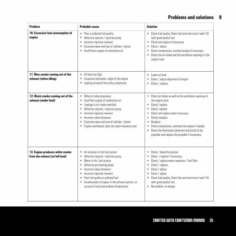
10. Excessive fuel consumption of engine
• Poor or polluted fuel quality • Defective injector / injection pump• Incorrect injection moment• Excessive wear and tear of cylinder / piston• Insufficient supply of combustion air
• Check fuel quality. Drain fuel tank and rinse it well. Fill with good quality fuel
• Check and replace if necessary • Check / adjust• Check compression, overhaul engine if necessary• Check the air intake and the ventilation openings in the
engine room
11. Blue smoke coming out of the exhaust (when idling)
• Oil level too high• Excessive inclination angle of the engine• Leaking oil seal of the turbo compressor
• Lower oil level• Check / adjust alignment of engine • Check / replace
12. Black smoke coming out of the exhaust (under load)
• Defecte turbocompressor• Insuffient supply of combustion air• Leakage in air intake manifold• Defective injector / injection pump• Incorrect injection moment• Incorrect valve clearance• Excessive wear and tear of cylinder / piston• Engine overheated, does not reach maximum rpm
• Check air intake as well as the ventilation openings in the engine room
• Check/ replace• Check/ replace• Check and replace when necessary• Check/readjust• Readjust• Check compression, overhaul the engine if needed• Check the dimensions (diameter and pitch) of the
propeller and replace the propeller if necessary.
13. Engine produces white smoke from the exhaust (at full load)
• Air inclusion in the fuel system• Defective injector / injection pump• Water in the fuel system• Defective pre-heating plugs • Incorrect valve clearance• Incorrect injection moment• Poor fuel quality or polluted fuel• Condensation of vapour in the exhaust system, on
account of very low ambient temperature
• Check / bleed the system• Check / replace if necessary• Check / replace water separator / fuel filter• Check / replace• Check / adjust• Check / adjust • Check fuel quality. Drain fuel tank and rinse it well. Fill
with good quality fuel• No problem, no danger
9

36 Crafted with CRAFTSMAN MARINE
Technical data
Bore x stroke:
Capacity:
Number of cylinders:
Compression ratio:
Order of fuel injection:
Maximum number of revolutions:
Maximum torque:
Maximum output at flywheel:
Fuel consumption at 1800 rpm:
Exhaust diameter:
Weight:
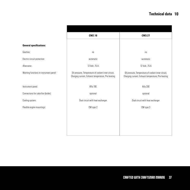
Basic engine:General specifications
Type of engine
CM2.16 CM3.27
Mitsubishi
76 x 70 mm
635 cm³
2 in line
23 : 1
IDI (indirect)
3600 rpm
29,3 Nm at 3600 rpm
11,8 kW/16 pk (ISO 8665/3046)
268 g/kW.h (196 g/pk.h)
Ø 40
90 kg
Mitsubishi
76 x 70 mm
952 cm³
3 in line
22 : 1
IDI (indirect)
3600 rpm
53,1 Nm at 3600 rpm
20 kW/27.2 pk (ISO 8665/3046)
270 g/kW.h (199 g/pk.h)
Ø 40
113 kg
10
37Crafted with CRAFTSMAN MARINE
Technical data
Gearbox:
Electric circuit protection:
Alternator:
Warning functions in instrument panel:
Instrument panel:
Connections for calorifier (boiler):
Cooling system:
Flexible engine mountings:
General specifications:
Type of engine
no
automatic
12 Volt, 75 A
Oil pressure, Temperature of coolant inner circuit, Charging current, Exhaust temperature, Pre-heating
Alfa 10E
optional
Dual circuit with heat exchanger
CM type 2
no
automatic
12 Volt, 75 A
Oil pressure, Temperature of coolant inner circuit, Charging current, Exhaust temperature, Pre-heating
Alfa 20E
optional
Dual circuit with heat exchanger
CM type 3
CM2.16 CM3.27
10
38 Crafted with CRAFTSMAN MARINE
Lubricants and cooling liquids
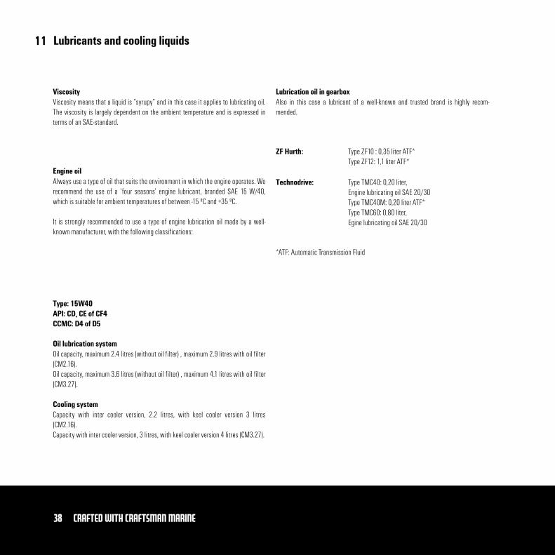
Also in this case a lubricant of a well-known and trusted brand is highly recom-mended.
Oil capacity, maximum 2.4 litres (without oil filter) , maximum 2.9 litres with oil filter (CM2.16).Oil capacity, maximum 3.6 litres (without oil filter) , maximum 4.1 litres with oil filter (CM3.27).
ViscosityViscosity means that a liquid is “syrupy” and in this case it applies to lubricating oil. The viscosity is largely dependent on the ambient temperature and is expressed in terms of an SAE-standard.
Engine oilAlways use a type of oil that suits the environment in which the engine operates. We recommend the use of a ‘four seasons’ engine lubricant, branded SAE 15 W/40, which is suitable for ambient temperatures of between -15 ºC and +35 ºC.
It is strongly recommended to use a type of engine lubrication oil made by a well-known manufacturer, with the following classifications:
Type: 15W40API: CD, CE of CF4CCMC: D4 of D5
Oil lubrication system
Capacity with inter cooler version, 2.2 litres, with keel cooler version 3 litres (CM2.16).Capacity with inter cooler version, 3 litres, with keel cooler version 4 litres (CM3.27).
Cooling system
Lubrication oil in gearbox
*ATF: Automatic Transmission Fluid
ZF Hurth:
Technodrive:
Type ZF10 : 0,35 liter ATF*Type ZF12: 1,1 liter ATF*
Type TMC40: 0,20 liter, Engine lubricating oil SAE 20/30Type TMC40M: 0,20 liter ATF*Type TMC60: 0,80 liter, Egine lubricating oil SAE 20/30
11
39Crafted with CRAFTSMAN MARINE
Lubricants and cooling liquids
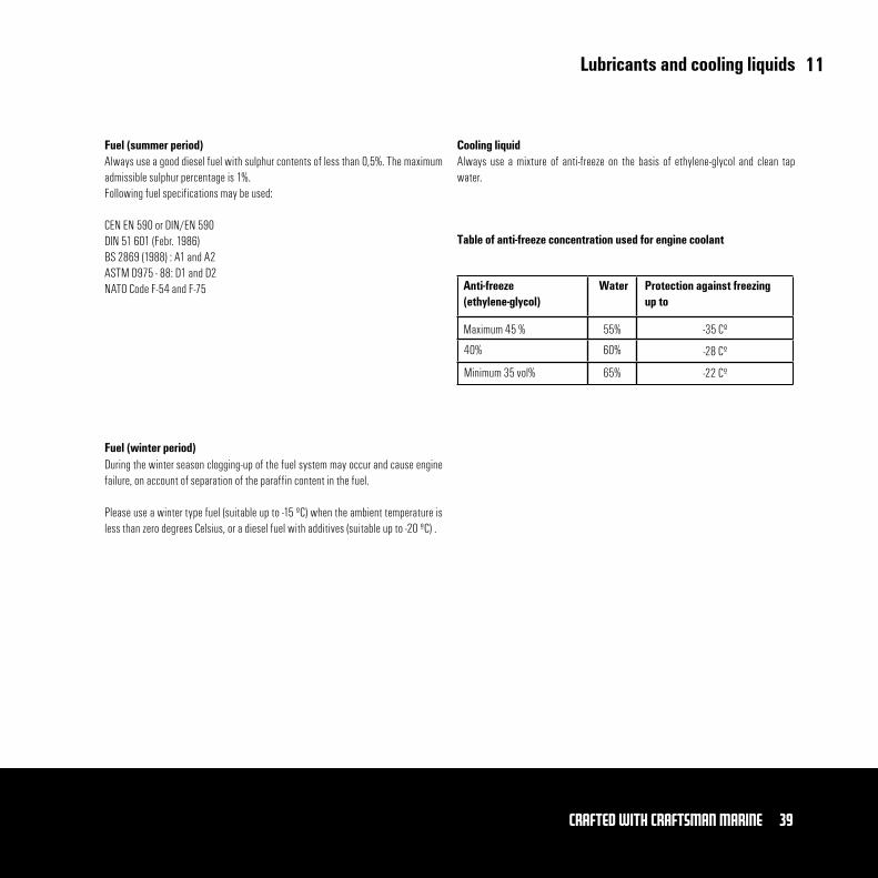
Fuel (summer period)Always use a good diesel fuel with sulphur contents of less than 0,5%. The maximum admissible sulphur percentage is 1%.Following fuel specifications may be used:
CEN EN 590 or DIN/EN 590 DIN 51 601 (Febr. 1986)BS 2869 (1988) : A1 and A2ASTM D975 - 88: D1 and D2NATO Code F-54 and F-75
Fuel (winter period)During the winter season clogging-up of the fuel system may occur and cause engine failure, on account of separation of the paraffin content in the fuel.
Please use a winter type fuel (suitable up to -15 ºC) when the ambient temperature is less than zero degrees Celsius, or a diesel fuel with additives (suitable up to -20 ºC) .
Cooling liquidAlways use a mixture of anti-freeze on the basis of ethylene-glycol and clean tap water.
Table of anti-freeze concentration used for engine coolant
Anti-freeze (ethylene-glycol)
Water Protection against freezing up to
Maximum 45 %
40%
Minimum 35 vol%
55%
60%
65%
-35 Cº
-28 Cº
-22 Cº
11
Fuel return Ø 8 mmFuel supply Ø 8 mm
ExhaustØ 40 mm
Sea Water Intake Ø 20 mm
40 Crafted with CRAFTSMAN MARINE
Overall Dimensions
Fuel return Ø 8 mmExhaust Ø 40 mm
Fuel supply Ø 8 mm
Sea Water Intake Ø 20 mm
12
ExhaustØ 40 mm
Fuel supply Ø 8mm
Sea Water Intake Ø 20 mm
41Crafted with CRAFTSMAN MARINE
Overall Dimensions
Fuel supply Ø 8 mmExhaust Ø 40 mm
Sea Water Intake Ø 20 mm
12
42 Crafted with CRAFTSMAN MARINE
Notes

43Crafted with CRAFTSMAN MARINE
Notes