Embed Size (px)
Citation preview
City of West Jordan Storm Drain Ch. 3 Pg. 1
Chapter Three STORM DRAIN DESIGN STANDARDS
1.01 GENERAL - It is the intent of this section to define West Jordan City=s policy regarding
surface and storm water management; to explain city review requirements and procedures; and to promote the general health, safety, and the welfare of West Jordan City residents by minimizing or eliminating potential dangers of flooding to life and property. Any variance from this document shall be subject to approval of the City Engineer.
1.02 DEFINITIONS - To shorten this document certain words or phrases are defined as follows
unless stated otherwise in said document.
A. Detention Storage: The storage of storm water runoff for controlled release during or immediately following the design storm event.
B. Discharge Point: A point or location where surface or storm water runoff is concentrated
before being released from the project area.
C. Emergency: Unforseen circumstance that presents immediate danger to persons or property. This also includes loss of utility services.
D. Erosion Control: Controlling the unwanted movement of soil from a project=s boundaries.
E. Freeboard: The distance from the top of a bank or embankment to the highwater elevation
during a design storm.
F. Groundwater: Concentrated water beneath the earth=s surface in aquifers of saturated soil and rock that supplies wells and springs.
G. Intensity-Duration-Frequency-Curve: (IDF Curve) a summary of the site=s rainfall
characteristics comparing storm duration and rainfall intensity.
H. Natural Drainage Channel: Drainage structures which naturally occur on a project prior to disturbance that convey storm water to a stream, creek, canal, or river.
I. Peak Flow: Maximum rate of storm water runoff at a point under investigation.
J. Permissible Shear Stress: The force required to begin movement of the channel bottom or
side slopes.
K. Roughness Coefficient: Used in Manning=s equation to estimate a material=s resistance to the flow of water.
L. Runoff Coefficient: Used in the rational method to estimate the permeability of ground cover
to water runoff.
M. Runoff Curve Number: Used in SCS peak runoff method to estimate the amount of water that will not infiltrate into the ground.
City of West Jordan Storm Drain Ch. 3 Pg. 2
N. Shallow Concentrated Flow: Storm water runoff concentrated in rills or gullies.
O. Sheet Flow: A shallow mass of storm water runoff in the upper reaches of a sub-basin.
P. Spillway: A waterway in or about an hydraulic structure, for the release of excess water.
Q. Spread: A measure of the transverse lateral distance from the curb face to the limit of the water flowing on the roadway.
R. Storm Water Pollution Prevention Plan: Drawing that pictorially displays erosion control
information to a contractor regarding a particular site.
S. Storm Water Runoff: Storm water runoff shall mean that water resulting from precipitation running off from the surface of a drainage area during and immediately following a cloudburst event.
T. Time of Concentration: The time for storm water runoff to travel from the hydraulically most
remote point in a drainage sub-basin to the point of investigation.
U. Tributary Drainage Area: Tributary drainage area shall mean the entire catchment area that contributes surface and storm water runoff to a given impact point under investigation.
1.03 REFERENCES
A. U.S. Department of Transportation, Federal Highway Administration, 2001. Urban Drainage Design Manual. Washington D.C., U.S. Department of Transportation.
B. Soil Conservation Service, 1986. Urban Hydrology for Small Watersheds. Technical
Release No. 55, U.S. Department of Agriculture.
C. TRC North American Weather Consultants, 1999. Rainfall Intensity Duration Analysis Salt Lake County, Utah.
D. Federal Emergency Management Agency. Flood Insurance Study Guidelines and
Specifications for Study Contractors. Washington, D.C., Federal Emergency Management Agency.
E. U.S. Department of Transportation, Federal Highway Administration, 1985. Hydraulic
Design of Highway Culverts. Washington D.C., U.S. Department of Transportation.
F. Virginia Department of Conservation and Historic Resources, 1992. Virginia Erosion and Sediment Control Handbook. 3rd ed. Richmond, Virginia. Virginia Department of Conservation and Historic Resources.
1.04 QUALITY ASSURANCE - Perform work in accordance with City drafting/submittal
requirements as described herein. Design work shall be accomplished under the direct supervision of a Utah Registered Professional Engineer, and shall carry the seal of the same supervising Professional Engineer.
City of West Jordan Storm Drain Ch. 3 Pg. 3
1.05 SUBMITTALS
A. Completed Checklist: A checklist is provided by the city and should be used as a guide in the preparation of all submittals required for drainage review and approval. These checklists are used by the reviewing agent to determine regulation compliance and plan and construction drawing completeness.
B. Overall Drainage Plan: This plan shall be prepared in accordance with the items outlined in
the Approval Checklist. Adherence to this list is strongly recommended to avoid delay in the Plan approval stage of the City=s drainage review.
C. Overall Grading Plan: Developer must submit a plan providing grading information for each
individual lot. Execution of plan will be required of each individual home builder. See sample provided at the end of the chapter.
D. Construction Drawings: The Drainage Plan shall be accompanied by a copy of all plan and
profile drawings pertaining to all proposed storm drains or storm drain facilities to be constructed in connection with the project. Similarly, detail drawings of special structures or appurtenances shall also be submitted when required.
E. Detail Drawings: When required, these drawings will give additional information regarding
the construction of products not standard in the city of West Jordan.
F. Storm Water Pollution Prevention Plan (SWPPP): Detailed plans and instructions to the contractor outlining the erosion control measures for the project.
G. Calculation Packet: An 8 2" x 11" bound packet of hydrologic information and
calculations, pavement drainage, hydraulic calculations of storm drains, stable channel design, storm water quantity control, storm water quality, additional design procedure information, and all supporting charts, tables, curves, figures, and certificates used in the overall drainage design shall be submitted.
H. Easements and Land Acquisition: Do not discharge storm water onto or through private
property without the appropriate easement. An access easement will be required whenever public storm drains are constructed in lands of private ownership. Easement agreement forms and procedures may be obtained by contacting the City Attorney=s Office. The following requirements will also apply.
1. All easements must be a minimum of 20 feet wide.
2. Easements shall extend 10 feet beyond the last manhole on a line.
3. All easements shall be submitted and approved by the City Engineer before Final
approval shall be granted.
City of West Jordan Storm Drain Ch. 3 Pg. 4
I. Required permits: May include but are not limited to state and county flood control permits, Railroad crossing permits, United States Army Corp. of Engineer permits, Utah Division of Water Quality permits, Utah Division of Water Rights permits, etc.
J. Letters From Irrigation Users: Prior to approval of the development, the developer shall
obtain the written approval of the water users of any ditch to be piped, or abandoned. 1.06 POLICIES
A. Drainage Review Policy: Any proposed construction on public or private property within the limits of West Jordan City requiring either a building permit application or formal approval by the City shall be subject to review and approval by the City Engineering Department. Sufficient information shall be provided to determine drainage characteristics inside and outside the project boundaries. If surrounding areas contribute surface and/or storm water runoff to the project area, this additional runoff must be addressed in the project design.
B. Drainage Approvals from other Governing Authorities: In the event that proposed
construction shall direct surface and/or storm water runoff to properties or facilities owned and maintained by agents other than West Jordan City, written proof or permission or approval from these agents must be provided prior to acceptance of drainage concepts and subsequent issuance of City drainage approval.
C. Restrictive Discharge Policy: the restrictive discharge policy requires on-site detention of all
surface and storm water runoff within a commercial, industrial, or multi-family project area, and restricts the eventual discharge of this runoff to a maximum allowable discharge rate of 0.20 cubic feet per second per acre of development. The amount of storm water may be further restricted by the capacity of existing storm drains, or drainage facilities, as determined by the City Engineer. In the event such additional restrictions are necessary, the Developer shall provide additional detention storage of a capacity designated by the City Engineer. The requirements of collection and the restriction of the quantity of runoff discharge necessitates the engineering design of on-site storage facilities, and encourages water quality treatment, as well as controlled runoff discharge through storm drain piping.
D. Design Discharge Point: Design discharge points shall be agreed upon prior to Plan
approval. For projects where the Restrictive Discharge Policy is not applicable, there is no established discharge rate restriction. However, pipe or channel discharge connections shall be limited to the capacity available for the project as determined in the review process. All development is required to connect to an a approved storm water system.
E. Natural Drainage Channels: During the course of the development the developer shall not
alter any natural drainage channel without obtaining permission therefor from the appropriate agency having jurisdiction over the drainage channel. As a rule, natural drainage channels will not be piped except at road crossings.
F. Storm Water Pollution Prevention: Any proposed construction on public or private property
within the limits of West Jordan City requiring either a building permit application or formal approval by the City shall submit an Storm Water Pollution Prevention Plan for review by the City Engineer.
City of West Jordan Storm Drain Ch. 3 Pg. 5
G. Water Quality: It is City policy and the developer=s responsibility wherever attainable to
restore, protect and maintain the chemical, physical, and biological integrity of City and State waters and to restore their beneficial uses. To do so, drainage design shall address the treatment of surface and storm water runoff, both wet-weather and dry-weather discharges.
H. High Ground Water Table: West Jordan City requires that "if a water table problem exists,
provisions will be made to control the water to ensure dry basements." Every effort should be made to ensure dry basements even so far to construct homes with limited or no basements.
I. Special Flood Hazard: Must adhere to sections 88-6-(401-409) of city code.
1.07 HYDROLOGIC INFORMATION
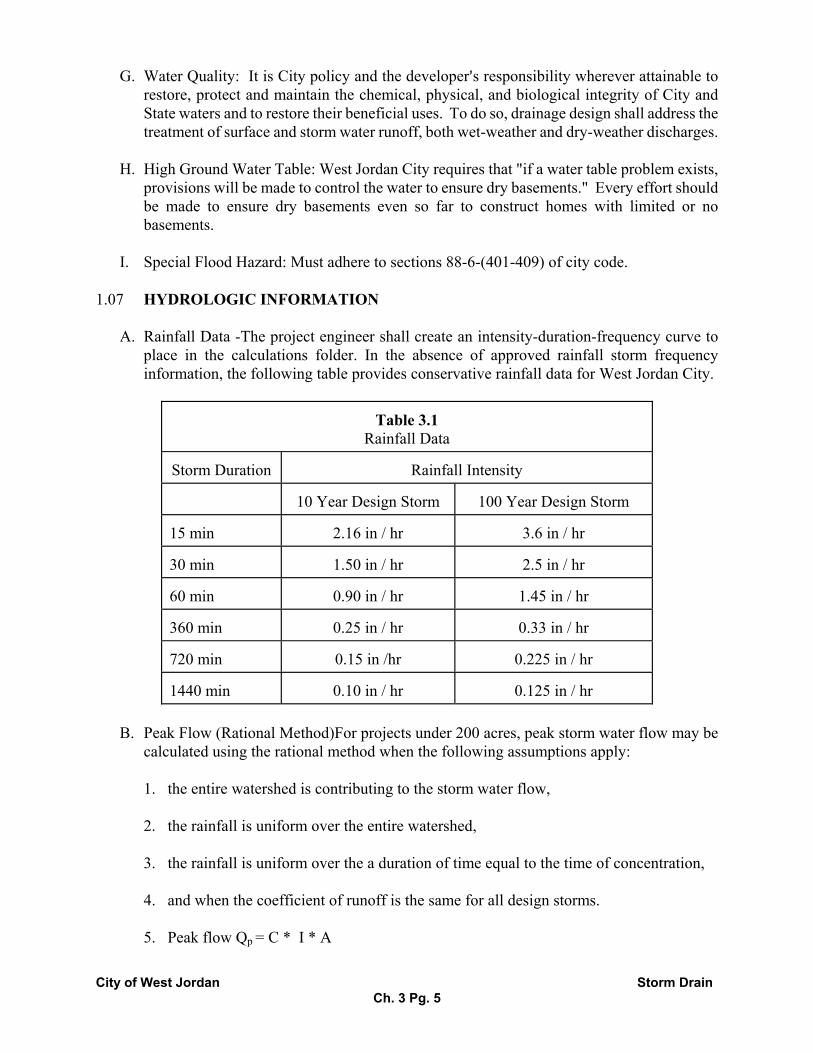
A. Rainfall Data -The project engineer shall create an intensity-duration-frequency curve to place in the calculations folder. In the absence of approved rainfall storm frequency information, the following table provides conservative rainfall data for West Jordan City.
Table 3.1 Rainfall Data
Storm Duration
Rainfall Intensity
10 Year Design Storm
100 Year Design Storm
15 min
2.16 in / hr
3.6 in / hr
30 min
1.50 in / hr
2.5 in / hr
60 min
0.90 in / hr
1.45 in / hr
360 min
0.25 in / hr
0.33 in / hr
720 min
0.15 in /hr
0.225 in / hr
1440 min
0.10 in / hr
0.125 in / hr
B. Peak Flow (Rational Method)For projects under 200 acres, peak storm water flow may be
calculated using the rational method when the following assumptions apply:
1. the entire watershed is contributing to the storm water flow,
2. the rainfall is uniform over the entire watershed,
3. the rainfall is uniform over the a duration of time equal to the time of concentration,
4. and when the coefficient of runoff is the same for all design storms.
5. Peak flow Qp = C * I * A
City of West Jordan Storm Drain Ch. 3 Pg. 6
Where C = weighted runoff coefficient, See Table 3.2,
I = rainfall intensity for design storm at time of concentration (in/hr),
A = tributary watershed area (acres)
C. Runoff Coefficient: Acceptable values for the runoff coefficient AC@ is shown in Table 3.2.
If a basin contains different types of ground cover a composited or weighted runoff coefficient can be calculated using the following formula:
1.
Table 3.2
Minimum Runoff Coefficient AC@ for Rational Method (Urban Drainage Design Manual)
Type of Drainage Area
Minimum Runoff Coefficient, AC@
Business: Downtown Area
0.70 - 0.95
Neighborhood Area
0.50 - 0.70
Residential: Single Family
0.30 - 0.50
Multi-Family
0.60 - 0.75
Apartment
0.50 - 0.70
Industrial: Light Area
0.50 - 0.80
Heavy Area
0.60 - 0.90
Lawns: Heavy Soil, flat, 2 %
0.13 - 0.17
Heavy Soil, average 2 - 7 %
0.18 - 0.22
Heavy Soil, steep, 7 %
0.25 - 0.35
Asphalt
0.85
Drives, walks
0.90
City of West Jordan Storm Drain Ch. 3 Pg. 7
Roofs
0.85
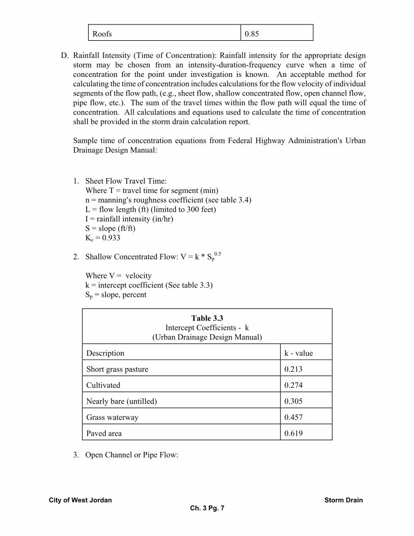
D. Rainfall Intensity (Time of Concentration): Rainfall intensity for the appropriate design
storm may be chosen from an intensity-duration-frequency curve when a time of concentration for the point under investigation is known. An acceptable method for calculating the time of concentration includes calculations for the flow velocity of individual segments of the flow path, (e.g., sheet flow, shallow concentrated flow, open channel flow, pipe flow, etc.). The sum of the travel times within the flow path will equal the time of concentration. All calculations and equations used to calculate the time of concentration shall be provided in the storm drain calculation report.
Sample time of concentration equations from Federal Highway Administration=s Urban Drainage Design Manual:
1. Sheet Flow Travel Time: Where T = travel time for segment (min) n = manning=s roughness coefficient (see table 3.4) L = flow length (ft) (limited to 300 feet) I = rainfall intensity (in/hr) S = slope (ft/ft) Kc = 0.933
2. Shallow Concentrated Flow: V = k * Sp
0.5
Where V = velocity k = intercept coefficient (See table 3.3) Sp = slope, percent
Table 3.3 Intercept Coefficients - k
(Urban Drainage Design Manual) Description
k - value
Short grass pasture
0.213
Cultivated
0.274
Nearly bare (untilled)
0.305
Grass waterway
0.457
Paved area
0.619
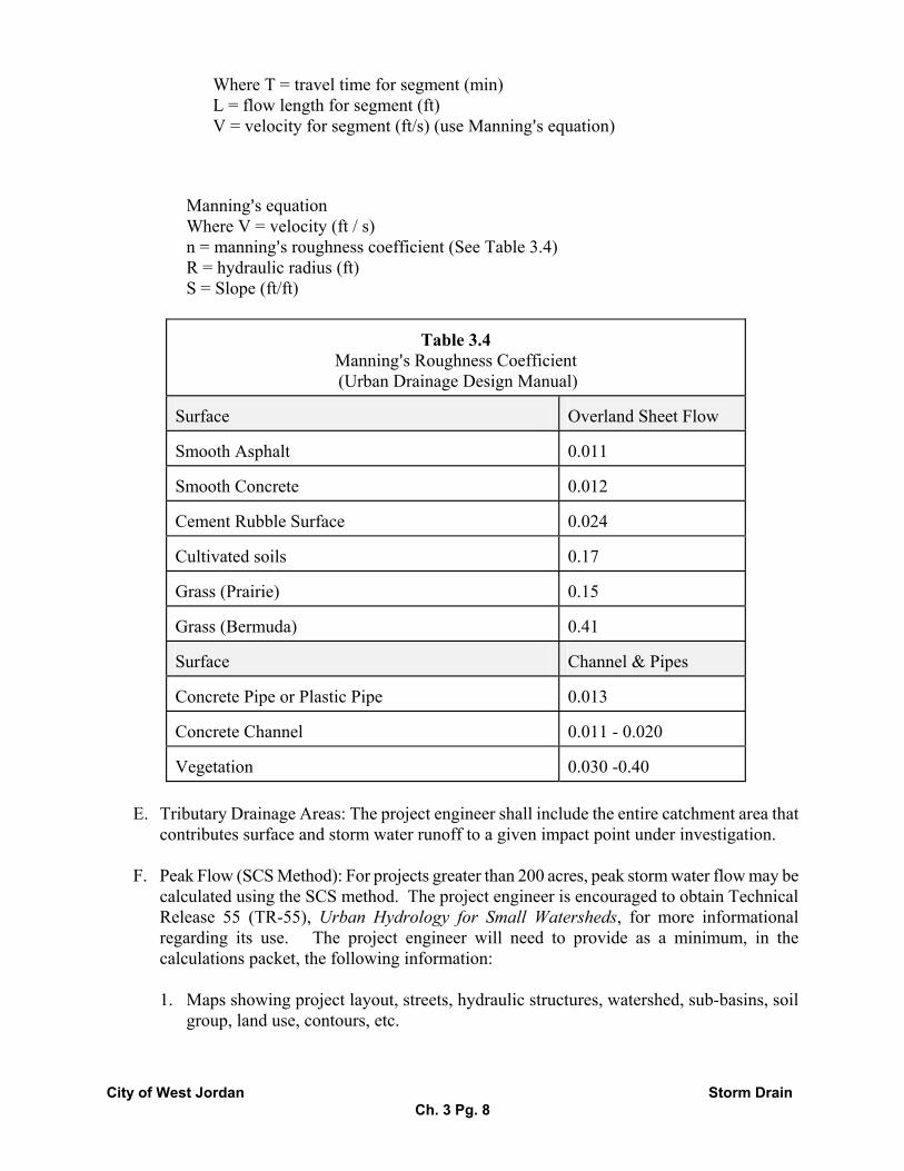
3. Open Channel or Pipe Flow:
City of West Jordan Storm Drain Ch. 3 Pg. 8
Where T = travel time for segment (min) L = flow length for segment (ft) V = velocity for segment (ft/s) (use Manning=s equation)
Manning=s equation Where V = velocity (ft / s) n = manning=s roughness coefficient (See Table 3.4) R = hydraulic radius (ft) S = Slope (ft/ft)
Table 3.4 Manning=s Roughness Coefficient (Urban Drainage Design Manual)
Surface
Overland Sheet Flow
Smooth Asphalt
0.011
Smooth Concrete
0.012
Cement Rubble Surface
0.024
Cultivated soils
0.17
Grass (Prairie)
0.15
Grass (Bermuda)
0.41
Surface
Channel & Pipes
Concrete Pipe or Plastic Pipe
0.013
Concrete Channel
0.011 - 0.020
Vegetation
0.030 -0.40
E. Tributary Drainage Areas: The project engineer shall include the entire catchment area that
contributes surface and storm water runoff to a given impact point under investigation.
F. Peak Flow (SCS Method): For projects greater than 200 acres, peak storm water flow may be calculated using the SCS method. The project engineer is encouraged to obtain Technical Release 55 (TR-55), Urban Hydrology for Small Watersheds, for more informational regarding its use. The project engineer will need to provide as a minimum, in the calculations packet, the following information:
1. Maps showing project layout, streets, hydraulic structures, watershed, sub-basins, soil
group, land use, contours, etc.
City of West Jordan Storm Drain Ch. 3 Pg. 9
2. Runoff Curve Number
3. Rainfall Data - For more information regarding this data contact the engineering department.
4. Time of Concentration information
5. Any other applicable data necessary to determine Qp
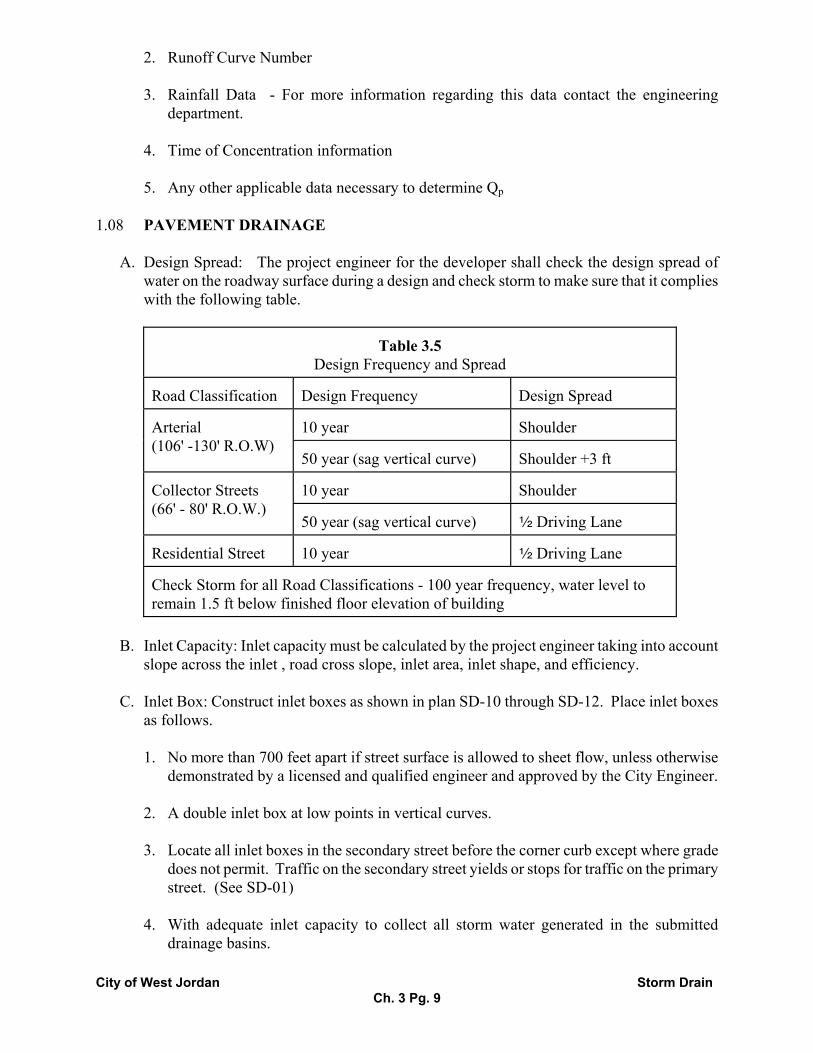
1.08 PAVEMENT DRAINAGE
A. Design Spread: The project engineer for the developer shall check the design spread of water on the roadway surface during a design and check storm to make sure that it complies with the following table.
Table 3.5 Design Frequency and Spread
Road Classification
Design Frequency
Design Spread
10 year
Shoulder
Arterial (106' -130' R.O.W)
50 year (sag vertical curve) Shoulder +3 ft
10 year
Shoulder
Collector Streets (66' - 80' R.O.W.)
50 year (sag vertical curve) 2 Driving Lane
Residential Street
10 year
2 Driving Lane
Check Storm for all Road Classifications - 100 year frequency, water level to remain 1.5 ft below finished floor elevation of building
B. Inlet Capacity: Inlet capacity must be calculated by the project engineer taking into account
slope across the inlet , road cross slope, inlet area, inlet shape, and efficiency.
C. Inlet Box: Construct inlet boxes as shown in plan SD-10 through SD-12. Place inlet boxes as follows.
1. No more than 700 feet apart if street surface is allowed to sheet flow, unless otherwise
demonstrated by a licensed and qualified engineer and approved by the City Engineer.
2. A double inlet box at low points in vertical curves.
3. Locate all inlet boxes in the secondary street before the corner curb except where grade does not permit. Traffic on the secondary street yields or stops for traffic on the primary street. (See SD-01)
4. With adequate inlet capacity to collect all storm water generated in the submitted
drainage basins.

City of West Jordan Storm Drain Ch. 3 Pg. 10
5. Prior to pedestrian ramps in high use pedestrian traffic areas.
1.09 HYDRAULIC STORM DRAIN DESIGN
A. Design Criteria: For drainage design of construction projects within West Jordan City, standard engineering practice will be followed. The following table governs the criteria for storm frequencies to be used in the design of storm drains:
Table 3.6
Storm Frequencies For Design Type of Structure
Minimum Design Storm Frequency
Gutters, inlets, pipes, boxes, roadside ditches,
10 year storm 24 hour storm
Streets, streams, natural channels, creeks, or rivers
100 year flood routing, 1 foot of freeboard for streams, creeks or channels during the 100 year event
Culvert
100 year storm (In addition to the design flow please give consideration to free board necessary to debris. Provide for bed load and debris bulking.)
Bridge
100 year storm (In addition to the design flow please give consideration to free board necessary to debris. Provide for bed load and debris bulking.)
B. Location: Storm drain lines should be placed as follows.
1. For a preferred street location see plan SD-01.
2. Side lot or rear lot property lines only if no other alternatives exist and as approved by
the City Engineer. If necessary, change street alignment to accommodate storm drain line placement.
3. Storm drain lines that are approved for side lot or rear lot installation shall have a
minimum 20 feet wide easement provided.
4. If storm drain lines are approved for side lot or rear lot installation, developer shall provide for vehicular access at all clean-out boxes, or manholes.
5. Extend storm drain lines beyond the boundary of the site development to meet the
system in the city=s storm drain master plan.
City of West Jordan Storm Drain Ch. 3 Pg. 11
C. Pipe Material, Size, and Construction:
1. All storm drain lines in the public right of way shall be reinforced concrete. Other types of pipe may be acceptable under certain conditions and must be approved by the City Engineer in writing.
2. The minimum diameter size of storm drain pipes within the public right-of-way shall be
15 inch.
3. If the City Master Plan shows a storm drain passing through the proposed development, which will service other areas, the developer will install the line of proper diameter. Credits may be given for the difference in cost of pipe material as defined in city code.
4. If easements are required across abutting property to permit construction of storm
sewers, the developer shall obtain such easements.
5. The storm drain line shall be constructed according to Plan SD-02.
D. Minimum Depth: As a rule, storm drain pipe shall be installed with a minimum cover of 2 foot from the top of the pipe to the roadway surface, however, written exceptions may be granted by the City Engineer.
E. Velocity Requirements: All sewer lines shall be designed and constructed for mean flow
velocities, when flowing full, of not less than 2.5 fps.
1. Manholes (or Clean-out Boxes) : Construct manholes, and clean-out boxes according to plans SD-04 through SD-14 and as follows.
1. All storm drain manholes in the public right-of -way shall be 5 feet in diameter.
2. Manholes shall be installed:
1. at the end of each line,
2. at all changes in pipe size, slope, or alignment;
3. at junctions with other lines,
4. within 10 feet of the upstream and downstream ends of an augured or trenched
casing,
5. and at intervals not to exceed 400 feet.
2. Cross Drain: Replacement only. Construct as per PLAN RD-12 and RD-13. 1.02 CHANNEL DESIGN
1. Channel Capacity - All channels shall be designed to convey the 100 year storm event with
City of West Jordan Storm Drain Ch. 3 Pg. 12
a minimum 1 foot of freeboard. The freeboard of a channel is defined as the vertical distance from the water surface to the top of the channel.
2. Channel Geometry - A typical channel cross section will consist of low flow area capable of
conveying a low flow storm event as well as a greater cross sectional area designed to carry the 100 year storm event.
3. Side Slopes - Maximum permissible side slopes without structural protection measures are 3
feet horizontal to 1 foot vertical.
4. Channel Slope - is typically dictated by the natural slope of the earth, however, if channel stability conditions warrant, it may be feasible to adjust the channel slope and location to achieve a stable condition. Drop structures, flexible linings, etc. may be required to protect against erosion.
5. Permissible Shear Stress - To create a stable channel, the permissible shear stress of a
channel may not be exceeded unless a flexible lining is provided as protection. Such lining may consist of grass, rip rap, concrete, etc. Provide information in the project calculation packet documenting assumptions, equations, and results of the shear stress comparison at critical locations in the channel.
6. Access: Access areas including access ramps shall be provided at intersection and road
crossings. 1.03 STORM WATER QUANTITY CONTROL FACILITIES
1. Design Frequency:
Storm Frequency for Storm Water Quantity Control Facility Type of Structure
Minimum Design Storm Frequency
On-site Detention Facility (Commercial, Industrial, Multi-family)
100 year 24 hour storm
Regional or Residential Detention
100 year 24 hour storm
Outlet Design
Multi-stage release (0.2 cfs per acre max.)
Spillway Design
100 year flood routing
Freeboard required
1 foot minimum
2. 100 Year Detention Capacity: All commercial, industrial, or multiple unit residential
development shall structurally provide:
The capacity of all design areas shall be sufficient to contain the estimated runoff volume from a 100 year, 24 hour storm event over those portions of the total project construction area under design. Adequate spillway provisions must be constructed to pass the peak rate
City of West Jordan Storm Drain Ch. 3 Pg. 13
of runoff from the 100 year, 24 hour storm event over the entire upstream tributary watershed assuming the outlet pipe for the detention facility to be inoperative.
3. 100 Year Detention Capacity: All regional or residential development shall structurally
provide:
The capacity of all design areas shall be sufficient to contain the estimated runoff volume from a 100 year, 24 hour storm event over those portions of the total project construction area under design. Adequate spillway provisions must be constructed to pass the peak rate of runoff from this 100 year, 24 hour storm event over the entire upstream tributary watershed assuming the outlet pipe for the detention facility to be inoperative.
4. Detention Pond Design:
1. When a pond is designed as multiple use, slopes on the ponds are not to exceed 4:1 to
allow neighborhood park development.
2. A landscaping plan, or maintenance plan must be included with all public detention pond submittals.
3. New detention basins are not to be located within 20 feet of residential property unless
no other options exist.
4. When located within 20 feet of a residential lot, a water barrier is to be installed on the edge of the pond to prevent water from saturating the footing area.
5. A fire hydrant shall be constructed within 100 feet from the outlet structure to facilitate
cleaning.
6. The detention pond shall be designed such that it may remain free of nuisance water.
7. All detention ponds shall be clay lined, unless approved otherwise by the City Engineer in writing.
8. All public detention facilities shall have a spillway to pass the check storm into a public
street.
9. Outlet structures shall be designed to be self cleaning.
10. Fencing may be required when depths exceed four feet.
11. Submission of an AAs Built@ Drawing of all public detention facilities is required.
5. Release Rate: The storage release rate of 0.20 cfs/acre of the gross aggregate project area shall be used to compute the required size of the discharge pipe when the detention storage facility is fifty (50%) full. The amount of storm water may be further restricted by the capacity of existing storm drains, or drainage facilities, as determined by the City Engineer. In the event such additional restrictions are necessary, the Developer shall provide additional
City of West Jordan Storm Drain Ch. 3 Pg. 14
detention storage of a capacity designated by the Director of Developmental Services.
6. Access: all detention facilities shall include access ramps that shall be a minimum of fifteen (15) feet in width and have a slope no greater than ten percent.
7. Temporary Facilities: The City may approve temporary drainage facilities providing for on-
site detention that will allow development to continue pending completion of the permanent storm drainage improvements. The temporary facilities shall provide the same level of flood protection at all times that will be provided by the completed systems. All costs of temporary facilities shall be paid by the developer in addition to the other costs and fees.
1.04 STORM WATER QUALITY
1. Best Management Practices : The project engineer shall also use Best Management practices in the design of storm water quality facilities in West Jordan. An example of said facilities may include but not be limited to:
1. Extended Detention Pond - similar to conventional detention ponds except storage times are extended to allow sediments to settle out. A modification to the extended detention pond may be a two stage extended detention pond. It is designed so that a small portion of the pond is used for water quality, and a larger portion is used for water quantity control.
2. Oil & Grease Separators - All residential detention ponds as well as commercial,
industrial, or multi-family developments shall be required as a minimum to install an oil, water, and grease separator immediately before they release storm water to the public system. Construct as per plan SD-17, or as approved by the City Engineer.
3. Pocket Wetlands - Wetland areas before discharge into a natural stream or channel will
use biological agents to clean storm water before it reaches a natural water course.
2. Storm Water Pollution Prevention: Prepare a Storm Water Pollution Prevention Plan as described in the end of the chapter. Please include a graphical representation of the proposed plan, as well as a sequence for the construction of erosion control elements. Such a plan should consider site management measures, structural erosion control measures, and soil stabilization measures. As a rule the general goals are to
1. Keep the soil at its original location,
2. Keep the soil close to its original location,
3. Keep the soil on-site.
3. Site Management Measures: May include:
1. A limit to the amount of disturbed area.
City of West Jordan Storm Drain Ch. 3 Pg. 15
2. A sequence of disturbance.
3. Identify specific areas that can be stabilized immediately after construction takes place.
4. Specify a maintenance schedule.
4. Soil Stabilization Measures: Include planting ground cover such as grasses, mulches, straw, etc. and temporary soil binders that must be sprayed onto soil.
5. Structural Erosion Control Measures: Structural controls typically intercept runoff before it
flows over disturbed areas, or divert it to a controlled area after it flows through a disturbed area. Such devices may consist of but not be limited to:
1. Check Dams- Intercept and ponds runoff allowing sediment to settle to the bottom of the
pond. May be made of a variety of materials including straw, stone, vegetated berm, etc.
2. Filter Fabric Fence - Also act to intercept and pond surface runoff. Allows water to exit through the silt fence leaving the sediment behind. Works well along a project boundary and on slopes.
3. Mulch - temporary stabilization of disturbed surfaces using mulch. It can protect the soil
form rainfall impacts and inhibits sheet flow. Will also protect re-seeded areas until natural vegetation has the chance to grow. Best used on slopes.
4. Slope Drains - collects storm water and transports it safely down a steep slope. Used in
connection with a check dam to prevent erosion of the slope.
5. Curb Inlet Barrier - last chance to prevent sediment from reaching the storm drain system. Sediment is typically removed by a filter which may be gravel, filter fabric, or other approved material before it is allowed to reach the inlet.
6. Inlet / Outlet Protection for Channels, Pipes, Inlets - Prevents erosion of channels,
streams, and ditches when a point discharge enters a natural system. Typically consists of rip rap, or concrete structure to absorb the energy of the discharge.
7. Sediment Basins- collect and store sediment transported by streams and ditches. Works
by reducing storm water velocity so that sediment will settle out. Used primarily when near a natural stream, channel , or waters of the United States of America.
8. Construction Entrances and Wash Down Pads - Prevent construction vehicles from
transporting sediment from the job site to a city street. Typically consist of gravel and a filter fabric.
9. Dust Control Measures - Prevent erosion of disturbed area by wind.
6. Rip Rap Design: The project engineer shall present separate design details regarding erosion
control at inlet and outlet=s of storm water systems. Proper rip rap design shall include:

City of West Jordan Storm Drain Ch. 3 Pg. 16
1. Depth of embedment (in.)
2. D50 design size (in.)
3. Length of apron (ft)
4. Width of apron at outlet (ft)
5. Width of apron at end of apron (ft)
6. Design discharge (cfs)
End of Section
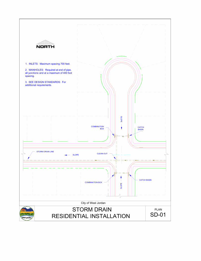
1. INLETS: Maximum spacing 700 feet.
2. MANHOLES: Required at end of pipe, all junctions and at a maximum of 400 foot spacing.
3. SEE DESIGN STANDARDS: For additional requirements.
STORM DRAIN LINE
City of West Jordan
STORM DRAINSD-01
PLAN
RESIDENTIAL INSTALLATION
CATCH BASIN
CATCH BASIN
CLEAN-OUT
COMBINATION BOX
SLO
PE
SLO
PE
SLOPE
COMBINATIONBOX
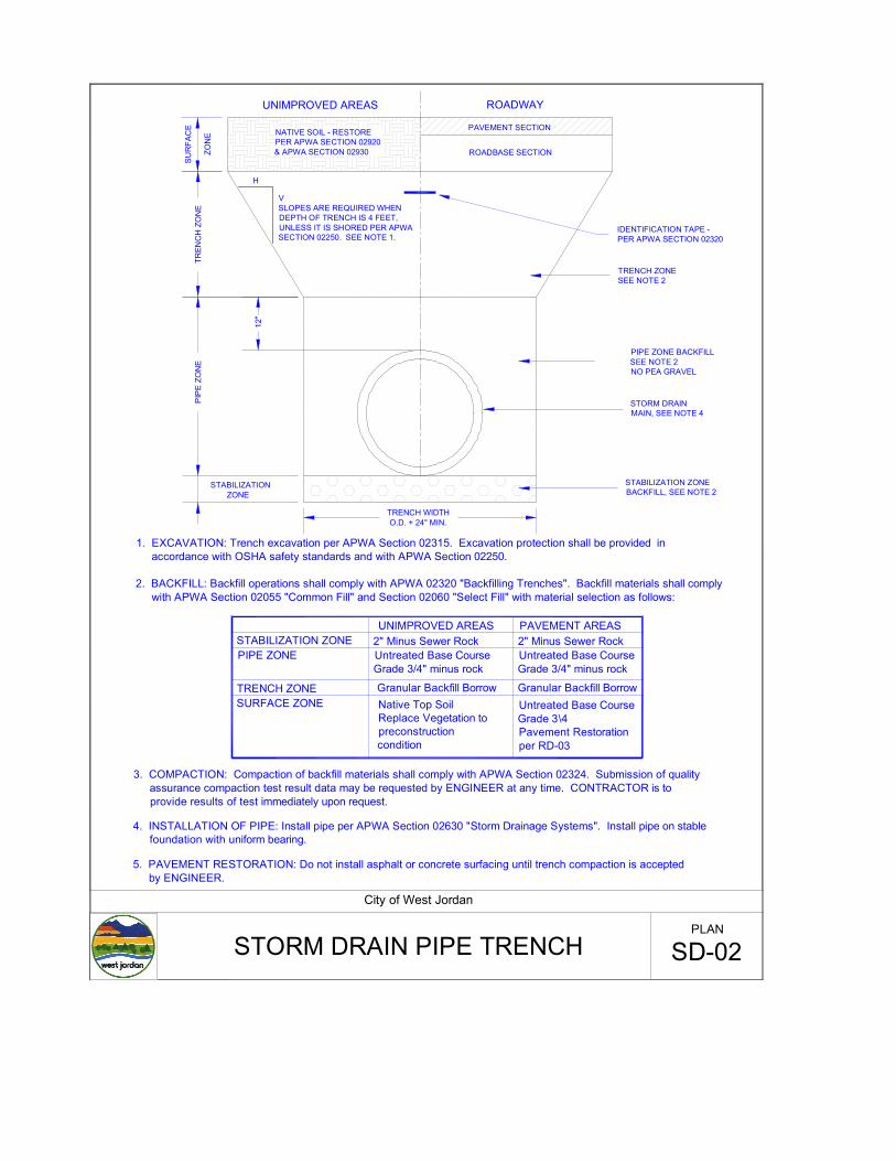
PAVEMENT SECTION
ROADBASE SECTION
TRENCH ZONESEE NOTE 2
PIPE ZONE BACKFILLSEE NOTE 2NO PEA GRAVEL
STORM DRAIN MAIN, SEE NOTE 4
IDENTIFICATION TAPE -PER APWA SECTION 02320
H
VSLOPES ARE REQUIRED WHEN DEPTH OF TRENCH IS 4 FEET, UNLESS IT IS SHORED PER APWA SECTION 02250. SEE NOTE 1.
1. EXCAVATION: Trench excavation per APWA Section 02315. Excavation protection shall be provided in accordance with OSHA safety standards and with APWA Section 02250.
2. BACKFILL: Backfill operations shall comply with APWA 02320 "Backfilling Trenches". Backfill materials shall comply with APWA Section 02055 "Common Fill" and Section 02060 "Select Fill" with material selection as follows:
UNIMPROVED AREAS
SURFACE ZONETRENCH ZONE
PIPE ZONESTABILIZATION ZONE
PAVEMENT AREAS2" Minus Sewer Rock
Granular Backfill BorrowNative Top Soil Replace Vegetation to preconstruction condition
2" Minus Sewer RockUntreated Base CourseGrade 3/4" minus rock
Granular Backfill BorrowUntreated Base CourseGrade 3\4Pavement Restoration per RD-03
3. COMPACTION: Compaction of backfill materials shall comply with APWA Section 02324. Submission of quality assurance compaction test result data may be requested by ENGINEER at any time. CONTRACTOR is to provide results of test immediately upon request.
4. INSTALLATION OF PIPE: Install pipe per APWA Section 02630 "Storm Drainage Systems". Install pipe on stable foundation with uniform bearing.
STABILIZATION ZONE BACKFILL, SEE NOTE 2
Untreated Base CourseGrade 3/4" minus rock
TREN
CH
ZO
NE
PIP
E ZO
NE
STABILIZATION ZONE
ROADWAYUNIMPROVED AREAS
NATIVE SOIL - RESTORE PER APWA SECTION 02920& APWA SECTION 02930
TRENCH WIDTHO.D. + 24" MIN.
12"
SU
RFA
CE
ZON
E
5. PAVEMENT RESTORATION: Do not install asphalt or concrete surfacing until trench compaction is accepted by ENGINEER.
City of West Jordan
STORM DRAIN PIPE TRENCH SD-02PLAN
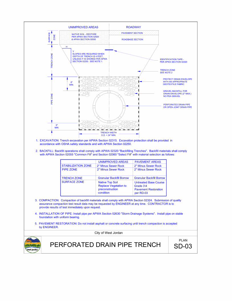
PAVEMENT SECTION
ROADBASE SECTION
TRENCH ZONESEE NOTE 2
GRAVEL BACKFILL FOR DRAIN ENVELOPE (2" MAX.)NO PEA GRAVEL
PERFORATED DRAIN PIPEOR OPEN JOINT DRAIN PIPE
IDENTIFICATION TAPE -PER APWA SECTION 02320
H
VSLOPES ARE REQUIRED WHEN DEPTH OF TRENCH IS 4 FEET, UNLESS IT IS SHORED PER APWA SECTION 02250. SEE NOTE 1.
1. EXCAVATION: Trench excavation per APWA Section 02315. Excavation protection shall be provided in accordance with OSHA safety standards and with APWA Section 02250.
2. BACKFILL: Backfill operations shall comply with APWA 02320 "Backfilling Trenches". Backfill materials shall comply with APWA Section 02055 "Common Fill" and Section 02060 "Select Fill" with material selection as follows:
UNIMPROVED AREAS
SURFACE ZONETRENCH ZONE
PIPE ZONESTABILIZATION ZONE
PAVEMENT AREAS2" Minus Sewer Rock
Granular Backfill BorrowNative Top Soil Replace Vegetation to preconstruction condition
2" Minus Sewer Rock2" Minus Sewer Rock
Granular Backfill BorrowUntreated Base CourseGrade 3\4Pavement Restoration per RD-03
3. COMPACTION: Compaction of backfill materials shall comply with APWA Section 02324. Submission of quality assurance compaction test result data may be requested by ENGINEER at any time. CONTRACTOR is to provide results of test immediately upon request.
4. INSTALLATION OF PIPE: Install pipe per APWA Section 02630 "Storm Drainage Systems". Install pipe on stable foundation with uniform bearing.
2" Minus Sewer Rock
TREN
CH
ZO
NE
PIP
E ZO
NE
6"MIN.
ROADWAYUNIMPROVED AREAS
NATIVE SOIL - RESTORE PER APWA SECTION 02920& APWA SECTION 02930
TRENCH WIDTHO.D. + 24" MIN.
SU
RFA
CE
ZON
E
5. PAVEMENT RESTORATION: Do not install asphalt or concrete surfacing until trench compaction is accepted by ENGINEER.
City of West Jordan
PERFORATED DRAIN PIPE TRENCH SD-03PLAN
PROTECT DRAIN ENVELOPEWITH AN APPROPRIATEGEOTEXTILE FABRIC
6"MIN.
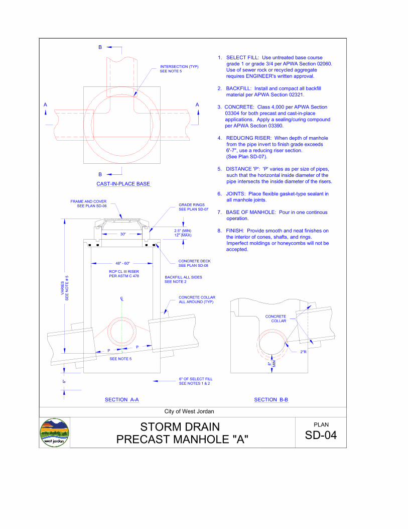
VAR
IES
SEE
NO
TE #
5
30"
48" - 60"
RCP CL III RISERPER ASTM C 478
2.5" (MIN)12" (MAX)
FRAME AND COVERSEE PLAN SD-06 GRADE RINGS
SEE PLAN SD-07
CONCRETE DECKSEE PLAN SD-08
CONCRETE COLLARALL AROUND (TYP)
BACKFILL ALL SIDESSEE NOTE 2
6" OF SELECT FILLSEE NOTES 1 & 26"
8" MI N
INTERSECTION (TYP)SEE NOTE 5
B
B
A A
CONCRETECOLLAR
CAST-IN-PLACE BASE
SECTION A-A SECTION B-B
PP
CL
2"R
SEE NOTE 5
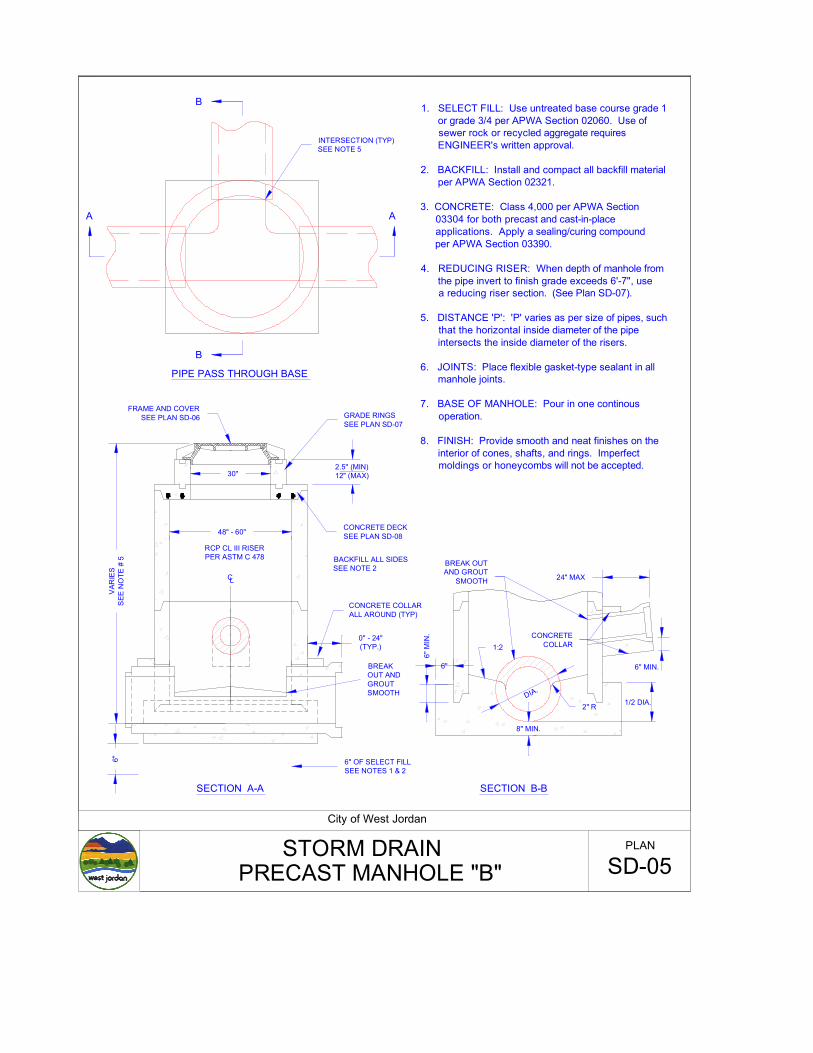
1. SELECT FILL: Use untreated base course grade 1 or grade 3/4 per APWA Section 02060. Use of sewer rock or recycled aggregate requires ENGINEER's written approval.
2. BACKFILL: Install and compact all backfill material per APWA Section 02321.
3. CONCRETE: Class 4,000 per APWA Section 03304 for both precast and cast-in-place applications. Apply a sealing/curing compound per APWA Section 03390.
4. REDUCING RISER: When depth of manhole from the pipe invert to finish grade exceeds 6'-7", use a reducing riser section. (See Plan SD-07).
5. DISTANCE 'P': 'P' varies as per size of pipes, such that the horizontal inside diameter of the pipe intersects the inside diameter of the risers.
6. JOINTS: Place flexible gasket-type sealant in all manhole joints.
7. BASE OF MANHOLE: Pour in one continous operation.
8. FINISH: Provide smooth and neat finishes on the interior of cones, shafts, and rings. Imperfect moldings or honeycombs will not be accepted.
City of West Jordan
STORM DRAINSD-04
PLAN
PRECAST MANHOLE "A"
VAR
IES
SEE
NO
TE #
5
30"
48" - 60"
RCP CL III RISERPER ASTM C 478
2.5" (MIN)12" (MAX)
FRAME AND COVERSEE PLAN SD-06 GRADE RINGS
SEE PLAN SD-07
CONCRETE DECKSEE PLAN SD-08
CONCRETE COLLARALL AROUND (TYP)
BACKFILL ALL SIDESSEE NOTE 2
6" OF SELECT FILLSEE NOTES 1 & 2
6"
INTERSECTION (TYP)SEE NOTE 5
B
B
A A
CONCRETECOLLAR
PIPE PASS THROUGH BASE
SECTION A-A SECTION B-B
CL
1. SELECT FILL: Use untreated base course grade 1 or grade 3/4 per APWA Section 02060. Use of sewer rock or recycled aggregate requires ENGINEER's written approval.
2. BACKFILL: Install and compact all backfill material per APWA Section 02321.
3. CONCRETE: Class 4,000 per APWA Section 03304 for both precast and cast-in-place applications. Apply a sealing/curing compound per APWA Section 03390.
4. REDUCING RISER: When depth of manhole from the pipe invert to finish grade exceeds 6'-7", use a reducing riser section. (See Plan SD-07).
5. DISTANCE 'P': 'P' varies as per size of pipes, such that the horizontal inside diameter of the pipe intersects the inside diameter of the risers.
6. JOINTS: Place flexible gasket-type sealant in all manhole joints.
7. BASE OF MANHOLE: Pour in one continous operation.
8. FINISH: Provide smooth and neat finishes on the interior of cones, shafts, and rings. Imperfect moldings or honeycombs will not be accepted.
BREAK OUT ANDGROUT SMOOTH
0" - 24"(TYP.)
24" MAX
6" MIN.
1/2 DIA.
6" M
IN.
6"
8" MIN.
DIA.
1:2
2" R
BREAK OUTAND GROUT
SMOOTH
City of West Jordan
STORM DRAINSD-05
PLAN
PRECAST MANHOLE "B"
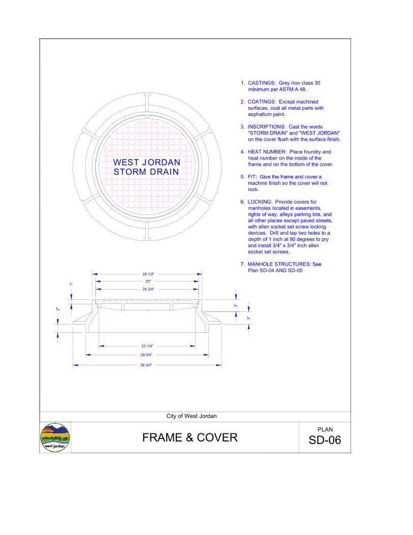
1. CASTINGS: Grey Iron class 30 minimum per ASTM A 48.
2. COATINGS: Except machined surfaces, coat all metal parts with asphaltum paint.
3. INSCRIPTIONS: Cast the words "STORM DRAIN" and "WEST JORDAN" on the cover flush with the surface finish.
4. HEAT NUMBER: Place foundry and heat number on the inside of the frame and on the bottom of the cover.
5. FIT: Give the frame and cover a machine finish so the cover will not rock.
6. LOCKING: Provide covers for manholes located in easements, rights of way, alleys parking lots, and all other places except paved streets, with allen socket set screw locking devices. Drill and tap two holes to a depth of 1 inch at 90 degrees to pry and install 3/4" x 3/4" inch allen socket set screws.
7. MANHOLE STRUCTURES: See Plan SD-04 AND SD-05
23 1/4"
29 3/4"
24 3/4"
25"
26 1/2"
1"
3 "
3"
2"
36 3/4"
WEST J ORDANSTORM DRAIN
City of West Jordan
FRAME & COVER SD-06PLAN
REINFORCEMENTSEE NOTE 2
TO CENTERLINE OF MANHOLE
TO CENTERLINE OF MANHOLE
RUBBER GASKET TO COMPLETELY FILL VOID
RING DETAIL GASKET DETAIL
VARIES
DECK SECTION
2.5" MINIMUM12" MAXIMUM
CONE SECTION
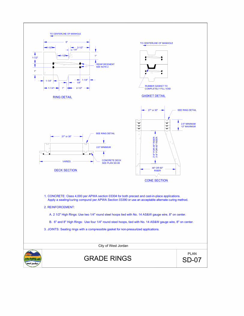
1. CONCRETE: Class 4,000 per APWA section 03304 for both precast and cast-in-place applications. Apply a sealing/curing compund per APWA Section 03390 or use an acceptable alternate curing method.
2. REINFORCEMENT:
A. 2 1/2" High Rings: Use two 1/4" round steel hoops tied with No. 14 AS&W gauge wire, 8" on center.
B. 6" and 8" High Rings: Use four 1/4" round steel hoops, tied with No. 14 AS&W gauge wire, 8" on center.
3. JOINTS: Seating rings with a compressible gasket for non-pressurized applications.
27" or 30"
2.5" MINIMUM
2-1/2"1-1/2"
6"
1-1/2" 1"1-1/2"
1"
1-1/4"
1-1/4"
1-1/4"1/4"
1" 2-1/2"
1/4"
27" or 30"
2'-6
" FO
R 4
8" R
ISER
3'-6
" FO
R 6
0" R
ISER
48" OR 60"RISER
SEE RING DETAIL
CONCRETE DECKSEE PLAN SD-08
SEE RING DETAIL
City of West Jordan
GRADE RINGS SD-07PLAN
27" OR 30"
OPENING
O.D. OF 60"MANHOLE SECTION
8"
2" CLR.
2" CLR.
#5 BAR
2" CLR.
8"
38" OR 44"
OPENING
27" OR 30"
OPENING
#5 BARS @ 6" O.C.BOTH DIRECTIONS
BOTTOM FACE
O.D. OF 60"MANHOLE SECTION
O.D. OF 48"MANHOLE SECTION
2" CLR.
6"
#5 BARS @ 6" O.C.BOTH DIRECTIONS
BOTTOM FACE
48" DECK
60" DECK 60" DECK
City of West Jordan
STANDARD CONCRETE DECK SD-08PLAN
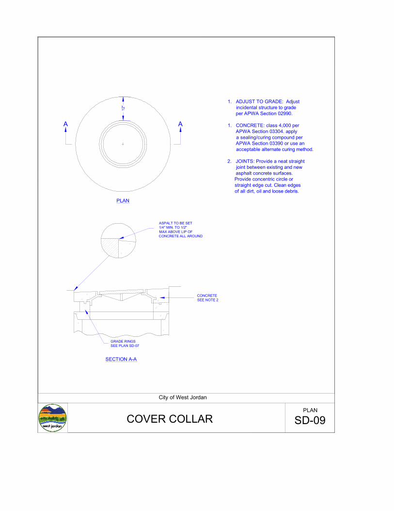
PLAN
ASPALT TO BE SET1/4" MIN. TO 1/2"MAX ABOVE LIP OF CONCRETE ALL AROUND
CONCRETESEE NOTE 2
GRADE RINGSSEE PLAN SD-07
SECTION A-A
A
1. ADJUST TO GRADE: Adjust incidental structure to grade per APWA Section 02990.
1. CONCRETE: class 4,000 per APWA Section 03304. apply a sealing/curing compound per APWA Section 03390 or use an acceptable alternate curing method.
2. JOINTS: Provide a neat straight joint between existing and new asphalt concrete surfaces. Provide concentric circle or straight edge cut. Clean edges of all dirt, oil and loose debris.
A12
"
City of West Jordan
COVER COLLAR SD-09PLAN
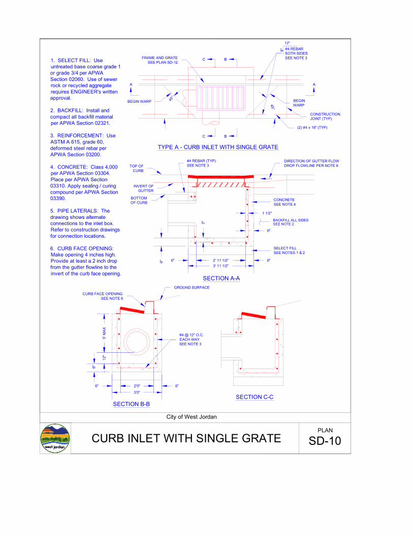
SECTION A-A
1. SELECT FILL: Use untreated base coarse grade 1 or grade 3/4 per APWA Section 02060. Use of sewer rock or recycled aggregate requires ENGINEER's written approval.
2. BACKFILL: Install and compact all backfill material per APWA Section 02321.
3. REINFORCEMENT: Use ASTM A 615, grade 60, deformed steel rebar per APWA Section 03200.
4. CONCRETE: Class 4,000 per APWA Section 03304. Place per APWA Section 03310. Apply sealing / curing compound per APWA Section 03390.
5. PIPE LATERALS: The drawing shows alternate connections to the inlet box. Refer to construction drawings for connection locations.
6. CURB FACE OPENING: Make opening 4 inches high. Provide at least a 2 inch drop from the gutter flowline to the invert of the curb face opening.
BACKFILL ALL SIDESSEE NOTE 2
1 1/2"
6"
3"
3' 11 1/2"2' 11 1/2" 6"6"6"
12"
8"
A
C B
C B
A
45°
45°
5' M
AX12
"
3'0"
2'0"6" 6"
SECTION C-CSECTION B-B
TYPE A - CURB INLET WITH SINGLE GRATE
GROUND SURFACECURB FACE OPENING
SEE NOTE 6
6"
#4 @ 12" O.C.EACH WAYSEE NOTE 3
SELECT FILLSEE NOTES 1 & 2
CONCRETESEE NOTE 4
BOTTOM OF CURB
INVERT OF GUTTER
TOP OF CURB
#4 REBAR (TYP)SEE NOTE 3
DIRECTION OF GUTTER FLOWDROP FLOWLINE PER NOTE 6
FRAME AND GRATESEE PLAN SD-12
#4 REBARSOTH SIDESSEE NOTE 3
BEGINWARP
CONSTRUCTIONJOINT (TYP)
(2) #4 x 18" (TYP)
BEGIN WARP
City of West Jordan
CURB INLET WITH SINGLE GRATE SD-10PLAN
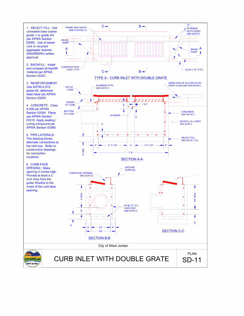
SECTION A-A
1. SELECT FILL: Use untreated base coarse grade 1 or grade 3/4 per APWA Section 02060. Use of sewer rock or recycled aggregate requires ENGINEER's written approval.
2. BACKFILL: Install and compact all backfill material per APWA Section 02321.
3. REINFORCEMENT: Use ASTM A 615, grade 60, deformed steel rebar per APWA Section 03200.
4. CONCRETE: Class 4,000 per APWA Section 03304. Place per APWA Section 03310. Apply sealing / curing compound per APWA Section 03390.
5. PIPE LATERALS: The drawing shows alternate connections to the inlet box. Refer to construction drawings for connection locations.
6. CURB FACE OPENING: Make opening 4 inches high. Provide at least a 2 inch drop from the gutter flowline to the invert of the curb face opening.
BACKFILL ALL SIDESSEE NOTE 23"
12"
8"
A
C B
C B
A
5' M
AX12
"
6"
3'0"
2'0"6" 6"
SECTION C-C
SECTION B-B
TYPE A - CURB INLET WITH DOUBLE GRATE
12"
3"
1 1/2"
#4 REBAR
7' 8"
2' 11 1/2" 2'11 1/2"6" 6"
6" M
IN
9"
45°
5'0"
MA
X.12
"
FRAME AND GRATESEE PLAN SD-12
BEGIN WARP
CONSTRUCTION JOINT (TYP)
#4 REBARBOTH SIDESSEE NOTE 2
BEGIN WARP
(2) #4 x 18" (TYP)
DIRECTION OF GUTTER FLOWDROP FLOWLINE PER NOTE 6
CONCRETESEE NOTE 4
SELECT FILLSEE NOTE 1 & 2
BOTTOMOF CURB
INVERTOF CURB
TOP OF CURB
#4 REBAR (TYP)SEE NOTE 3
GROUND SURFACE
CURB FACE OPENINGSEE NOTE 6
#4 @ 12" O.C.EACH WAYSEE NOTE 3
City of West Jordan
CURB INLET WITH DOUBLE GRATE SD-11PLAN
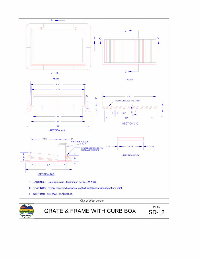
1. CASTINGS: Grey Iron class 30 minimum per ASTM A 48.
2. COATINGS: Except machined surfaces, coat all metal parts with asphaltum paint.
3. INLET BOX: See Plan SD-10,SD-11.
SECTION B-B
A
SECTION C-C
CC
B
B
D
D
PLAN PLAN
15 1/5" 1 1/8"1.125"
SECTION D-D
36 1/2"
35 1/2"
6"
2"
43"
36"
33"
35 1/2"
33"
5/8"
55°
12 EQUAL SPACES AT 2 13/16"
2"
SECTION A-A
6"17 3/4"
24"
31"
4"
6"
CURB BOX ADJUSTS6" TO 9"
STAINLESS STEEL BOLTS,NUTS AND WASHERS
City of West Jordan
GRATE & FRAME WITH CURB BOX SD-12PLAN
WEST JORDANSTORM DRAIN
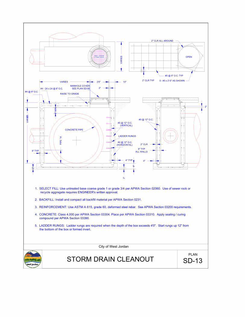
1. SELECT FILL: Use untreated base coarse grade 1 or grade 3/4 per APWA Section 02060. Use of sewer rock or recycle aggregate requires ENGINEER's written approval.
2. BACKFILL: Install and compact all backfill material per APWA Section 0231.
3. REINFORCEMENT: Use ASTM A 615, grade 60, deformed steel rebar. See APWA Section 03200 requirements.
4. CONCRETE: Class 4,000 per APWA Section 03304. Place per APWA Section 03310. Apply sealing / curing compound per APWA Section 03390.
5. LADDER RUNGS: Ladder rungs are required when the depth of the box exceeds 4'0". Start rungs up 12" from the bottom of the box or formed invert.
MANHOLE COVERSEE PLAN SD-06
3"
VAR
IES8"
RAISE TO GRADE
(VERTICAL)#5 @ 12" O.C.
#4 @ 12" O.C.(HORIZONTAL)
LADDER RUNGS
9" M
IN.
CONCRETE PIPE
4" TYP
#5 @ 12" O.C.
2" CLR
8" TYPALL WALLS
3"
9"
VARIES 2'6" 10"
2"
PIPE
°/4
#4 @ 9" O.C.#4 - 24 x 24 @ 8" O.C.
4"
VAR
IES
2" CLR TYP
#5 @ 9" O.C. TYP
5 - #5 x 2'-5" AS SHOWN
2" CLR ALL AROUND
OPEN
2"
8" TYP
City of West Jordan
STORM DRAIN CLEANOUT SD-13PLAN
A
PLAN
1' 3"
2'-0"
2'-11 1/2"
4'-3 1/2"
1"-5
3/ 4
"
#4 @ 12" O.C.EACH WAYSEE NOTE 3
SELECT FILLSEE NOTES 1 & 2
BACKFILL ALL AROUNDSEE NOTE 2
1 1/2"
CONCRETE SEE NOTE 4
12"
INLET OR OUTLET PIPESEE NOTE 5
VARIES6"
SECTION A-A
CONCRETE COLLARSEE PLAN SD-09
COVER AND FRAMESEE PLAN SD-06
GRADE RINGSSEE PLAN SD-07
#4 @ 6" O.C.EACH WAY
GRATE AND FRAMESEE PLAN SD-12
CURB FACE OPENING
SEE NOTE 6
4"
5'-0"MAX
6"
6" MIN
3"
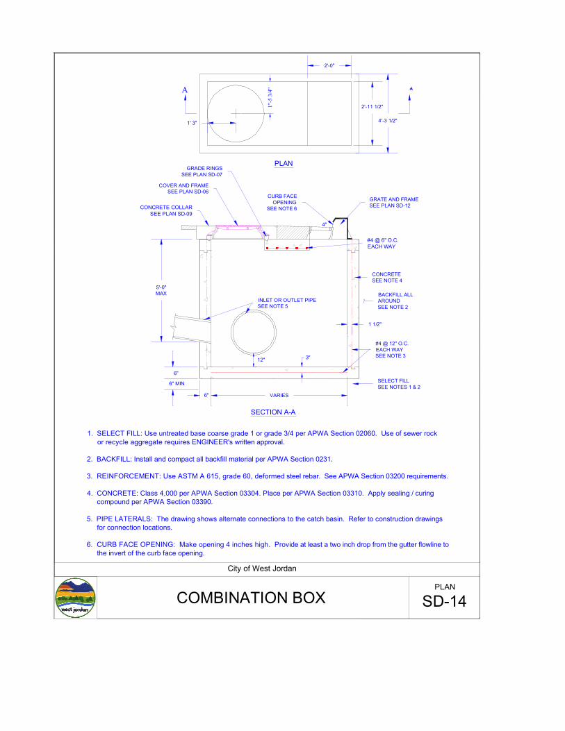
1. SELECT FILL: Use untreated base coarse grade 1 or grade 3/4 per APWA Section 02060. Use of sewer rock or recycle aggregate requires ENGINEER's written approval.
2. BACKFILL: Install and compact all backfill material per APWA Section 0231.
3. REINFORCEMENT: Use ASTM A 615, grade 60, deformed steel rebar. See APWA Section 03200 requirements.
4. CONCRETE: Class 4,000 per APWA Section 03304. Place per APWA Section 03310. Apply sealing / curing compound per APWA Section 03390.
5. PIPE LATERALS: The drawing shows alternate connections to the catch basin. Refer to construction drawings for connection locations.
6. CURB FACE OPENING: Make opening 4 inches high. Provide at least a two inch drop from the gutter flowline to the invert of the curb face opening.
City of West Jordan
COMBINATION BOX SD-14PLAN
4'10"
2'5-3/4"SECTION A-A
#4 BARS @12" O.C.ALL STEEL IS DOWELL GRATE
5/8" STEEL
2' 2-1/4"
18"
2'3"
3'3"
MECHANISMPROVIDE HINGE
6"
A
6"
4'6"
6"
PLAN
B
A
1/4"x1-1/2"STEEL TYP.
3'6"
6"
B
4' 0"
#4 BARS @12" O.C.
SECTION B-B
8"
2" TYP.
6"
ALL STEEL IS
W/CHAIN AND LOCK LOOP CAST IN PLACE
PROVIDE LOCKING MECHANISM
6"
3'3"
8"
MAXIMUM18" PIPE
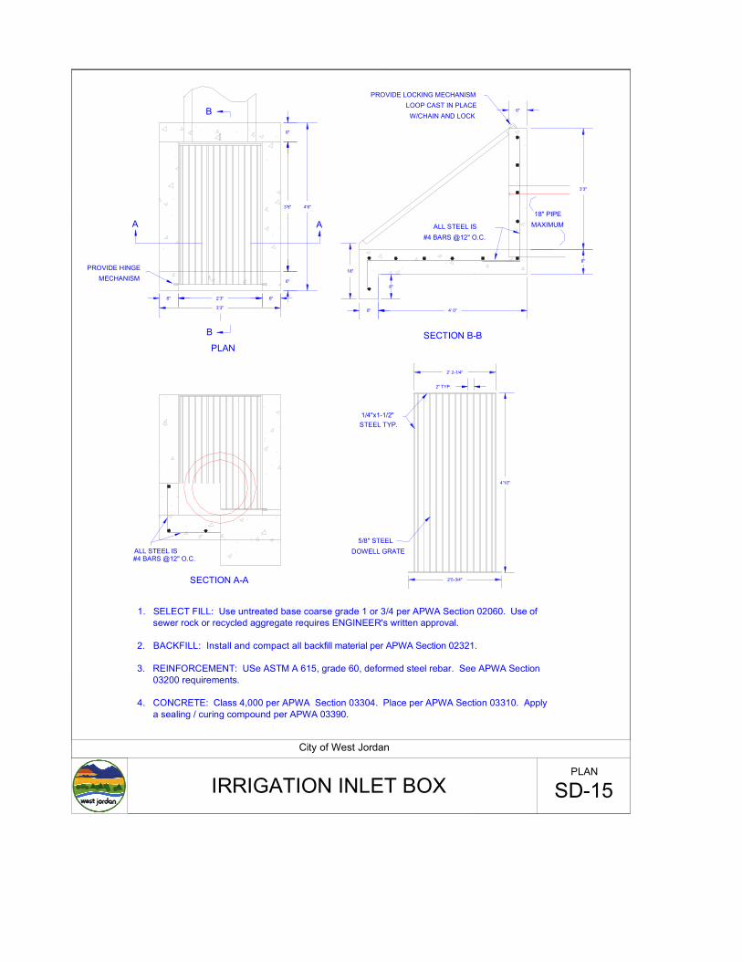
1. SELECT FILL: Use untreated base coarse grade 1 or 3/4 per APWA Section 02060. Use of sewer rock or recycled aggregate requires ENGINEER's written approval.
2. BACKFILL: Install and compact all backfill material per APWA Section 02321.
3. REINFORCEMENT: USe ASTM A 615, grade 60, deformed steel rebar. See APWA Section 03200 requirements.
4. CONCRETE: Class 4,000 per APWA Section 03304. Place per APWA Section 03310. Apply a sealing / curing compound per APWA 03390.
City of West Jordan
IRRIGATION INLET BOX SD-15PLAN
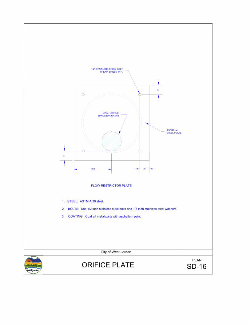
1. STEEL: ASTM A 36 steel.
2. BOLTS: Use 1/2 inch stainless steel bolts and 1/8 inch stainless steel washers.
3. COATING: Coat all metal parts with asphaltum paint.
2"
2"
2"
FLOW RESTRICTOR PLATE
1/2" STAINLESS STEEL BOLTw/ EXP. SHIELD TYP.
1/4" GALV.STEEL PLATE
DIAM. ORIFICE(DRILLED OR CUT)
W/2
City of West Jordan
ORIFICE PLATE SD-16PLAN
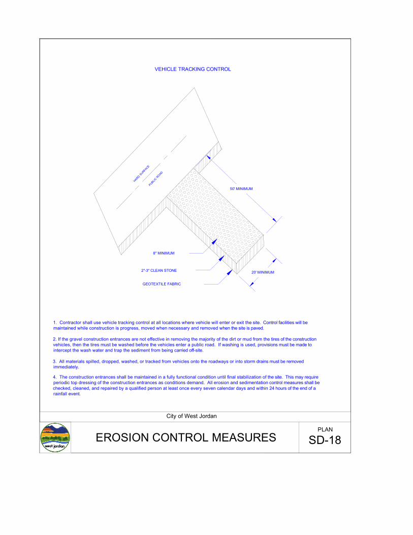
VEHICLE TRACKING CONTROL
HARD SURFA
CEPUBLIC
ROAD
GEOTEXTILE FABRIC
2"-3" CLEAN STONE
8" MINIMUM
20' MINIMUM
50' MINIMUM
City of West Jordan
EROSION CONTROL MEASURES SD-18PLAN
1. Contractor shall use vehicle tracking control at all locations where vehicle will enter or exit the site. Control facilities will be maintained while construction is progress, moved when necessary and removed when the site is paved.
2. If the gravel construction entrances are not effective in removing the majority of the dirt or mud from the tires of the construction vehicles, then the tires must be washed before the vehicles enter a public road. If washing is used, provisions must be made to intercept the wash water and trap the sediment from being carried off-site.
3. All materials spilled, dropped, washed, or tracked from vehicles onto the roadways or into storm drains must be removed immediately.
4. The construction entrances shall be maintained in a fully functional condition until final stabilization of the site. This may require periodic top dressing of the construction entrances as conditions demand. All erosion and sedimentation control measures shall be checked, cleaned, and repaired by a qualified person at least once every seven calendar days and within 24 hours of the end of a rainfall event.


![UK Standards [00700B01] - University of Kentucky · Web viewBOILER INSTALLATION 23 DUCTWORK SPECIFICATIONS 23 FLOOR DRAIN SPECIFICATIONS 23 GENERAL VALVE STANDARDS 23 HEATING, VENTILATION](https://img.pdfslide.us/doc/110x75/5aa077137f8b9a89178e165e/docuk-standards-00700b01-university-of-kentucky-viewboiler-installation-23.jpg)