Embed Size (px)
Citation preview
52
CHAPTER 8
ANALYSIS USING ANSYS MAXWELL SOFTWARE
8.1 Ansys Maxwell Software
The Ansys Maxwell software is widely used in designing and optimizing electrostatic,
electromagnetic and eddy current problems. It is based on finite element method. In this
method minimization of potential energy is considered. Therefore 3D model is used. In
IEEE model also used rod type electrode in similar manner. In this software solution is
done by dividing the volume within the critical cylinder into number of tetrahedrons and
start to analyses the potential distribution in various elements attached with previous set
of elements. Thus continuous solution can be obtained within the specified boundaries of
the critical cylinder.
8.2 Simulation results.
8.2.1 Design Summery Report generated by Ansys Maxwell V.16
Figure 38: Design Details
53
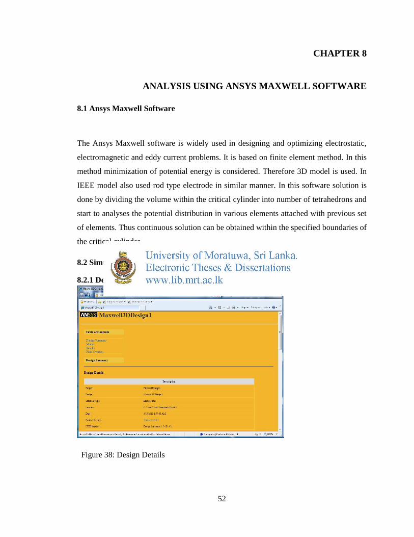
Figure 39: Model
To simulate the earth electrode the core and the pit should be modeled in 3-D plane with
real dimensions of earth pits. Also a simulation region should be defined to perform
simulations. Material properties are assigned to each element and the current is applied
to the top surface of the core. The simulations are done within the specified region.
Figure 40: Field Overlays
54
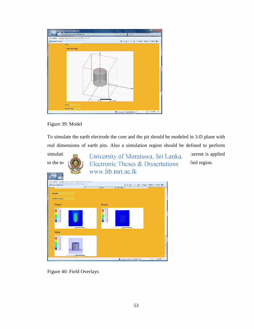
In this section all the field simulations done in the project are appeared as a summery. In
the simulated example it shows the variation of Voltage, Energy and the Mesh which is
used in simulation by FEM.
8.2.2 Discussion of simulation results
Figure 41: Energy variation in the XZ Plane
As per the results of Ansys Maxwell simulation software, it was found that the inner
cylinder close to the earth rod absorbed more energy and the stresses around it increases.
This can be used to simulate the earth resistance by getting the simulation results on
power loss inside the earth pit.
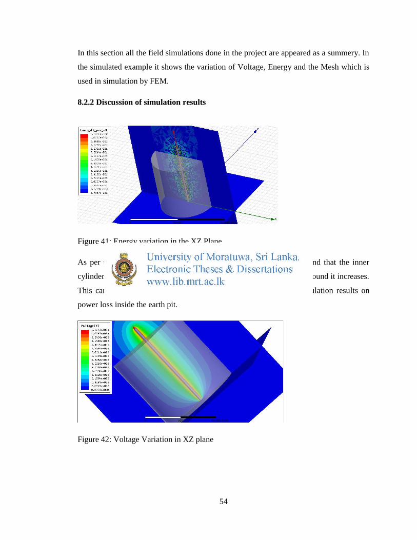
Figure 42: Voltage Variation in XZ plane
55
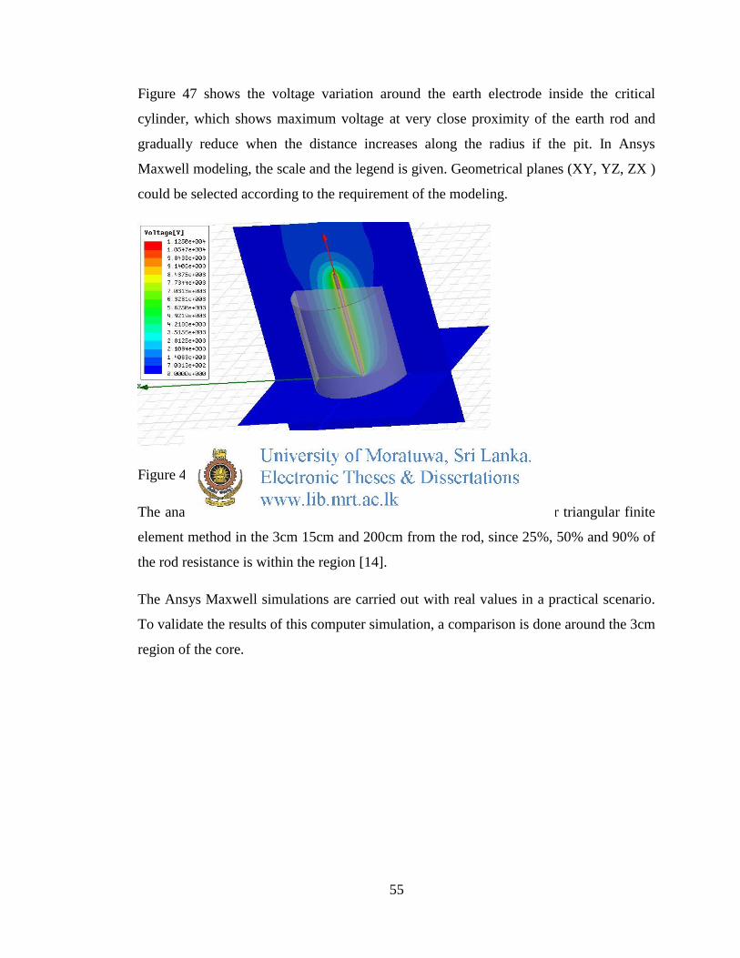
Figure 47 shows the voltage variation around the earth electrode inside the critical
cylinder, which shows maximum voltage at very close proximity of the earth rod and
gradually reduce when the distance increases along the radius if the pit. In Ansys
Maxwell modeling, the scale and the legend is given. Geometrical planes (XY, YZ, ZX )
could be selected according to the requirement of the modeling.
Figure 43: Voltage Variation in XZ plane
The analysis of the grounding rod has been carried out with first order triangular finite
element method in the 3cm 15cm and 200cm from the rod, since 25%, 50% and 90% of
the rod resistance is within the region [14].
The Ansys Maxwell simulations are carried out with real values in a practical scenario.
To validate the results of this computer simulation, a comparison is done around the 3cm
region of the core.
56
For the 3 cm region.
Applied voltage to the rod =11250V
Therefore total potential Drop=11250V
Potential within 3cm region= 8437V
Therefore potential drop within the 3cm region= 11250V-8550V
=2700V
Voltage drop as a percentage = 2700
11250X100 = 24%
For the 15 cm region.
Applied voltage to the rod =11250V
Therefore total potential Drop=11250V
Potential within 15cm region= 5710V
Therefore potential drop within the 15cm region= 11250V-5710V
=5540V
Voltage drop as a percentage = 5540
11250X100 = 49.24%
For the 200 cm region.
Applied voltage to the rod =11250V
Therefore total potential Drop=11250V
Potential within 200cm region= 703.13V
57
Therefore potential drop within the 200 cm region= 11250V-703.13V
=10546.87V
Voltage drop as a percentage = 10546
11250X100 = 93.7%
In the computer model a current of 10kA is applied, therefore the potential is
proportional to the Earth resistance.
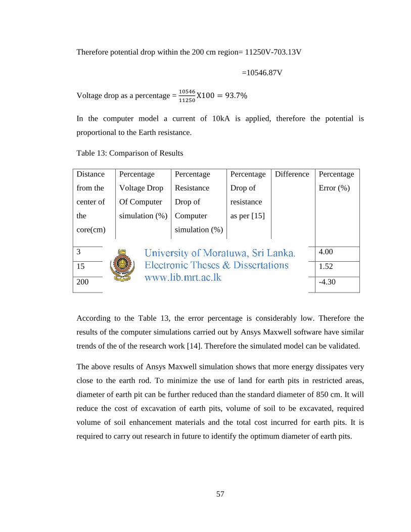
Table 13: Comparison of Results
Distance
from the
center of
the
core(cm)
Percentage
Voltage Drop
Of Computer
simulation (%)
Percentage
Resistance
Drop of
Computer
simulation (%)
Percentage
Drop of
resistance
as per [15]
Difference Percentage
Error (%)
3 24 24 25 1 4.00
15 49.24 49.24 50 0.76 1.52
200 93.7 93.7 90 -3.7 -4.30
According to the Table 13, the error percentage is considerably low. Therefore the
results of the computer simulations carried out by Ansys Maxwell software have similar
trends of the of the research work [14]. Therefore the simulated model can be validated.
The above results of Ansys Maxwell simulation shows that more energy dissipates very
close to the earth rod. To minimize the use of land for earth pits in restricted areas,
diameter of earth pit can be further reduced than the standard diameter of 850 cm. It will
reduce the cost of excavation of earth pits, volume of soil to be excavated, required
volume of soil enhancement materials and the total cost incurred for earth pits. It is
required to carry out research in future to identify the optimum diameter of earth pits.
58
By reducing the diameter of earth pits, public protests and objections can be minimized
to increase the efficiency and effectiveness of construction works related to distribution
transformers in restricted areas.