Embed Size (px)
Citation preview

Chamber Dynamic Response, Laser Driver-Chamber Interface and
System Integration for Inertial Fusion Energy
Mark Tillack
Farrokh Najmabadi
Rene Raffray
First IAEA-CRP-RCM on
“Elements of Power Plant Design for Inertial Fusion Energy”May 21-25, 2001
IAEA Headquarters, Vienna

Outline
• ARIES power plant studies program
• Assessment of IFE chambers
• Laser driver-chamber interface studies
• Final optics damage
• Beam propagation through chamber media
• Chamber dynamic response and clearing
• Numerical modeling
• Simulation experiments

Analyze & assess integrated, self-consistent IFE chamber concepts
Understand trade-offs and identify design windows for promising concepts. The research is not aimed at developing a point design.
Identify existing data base and extrapolations needed for each promising concept. Identify high-leverage items for R&D:
• What data is missing? What are the shortcomings of present tools?
• For incomplete database, what is being assumed and why?
• For incomplete database, what is the acceptable range of data? Would it make a difference to first order, i.e., does it make or break the concept?
• Start defining needed experiments and simulation tools.
Goals of ARIES Integrated IFE Chamber Analysis and Assessment Research

ARIES-IFE is a Multi-Institutional Effort
Program ManagementF. Najmabadi
Les Waganer (Operations)
Mark Tillack (System Integration)
Program ManagementF. Najmabadi
Les Waganer (Operations)
Mark Tillack (System Integration)Advisory/Review
Committees
Advisory/Review
Committees
OFESOFESExecutive Committee
(Task Leaders)
Executive Committee
(Task Leaders)
Fusion
Labs
Fusion
Labs
• Target Fab. (GA, LANL*)
• Target Inj./Tracking (GA)
• Chamber Physics (UW, UCSD)
• Chamber Eng. (UCSD, UW)
• Parametric Systems Analysis (UCSD, BA, LLNL)
• Materials (ANL)
• Target Physics (NRL*, LLNL*, UW)
• Drivers* (NRL*, LLNL*, LBL*)
• Final Optics & Transport
(UCSD, LBL , PPPL, MIT, NRL*,LLNL*)
• Safety & Env. (INEEL, UW, LLNL)
• Tritium (ANL, LANL*)
• Neutronics, Shielding (UW, LLNL)
Tasks
* voluntary contributions

An Integrated Assessment Defines the R&D Needs
Characterization
of target yield
Characterization
of target yield
Target
Designs
Chamber
ConceptsCharacterization
of chamber response
Characterization
of chamber response
Chamber
environment
Chamber
environment
Final optics &
chamber propagation
Final optics &
chamber propagation
Chamber R&D:Data base
Critical issues
Chamber R&D:Data base
Critical issues
DriverDriver
Target fabrication,
injection, and tracking
Target fabrication,
injection, and tracking
Assess & Iterate

Status of ARIES-IFE Study
Six combinations of target and chamber concepts are under investigation:
Nearly Complete,
Documentation
Direct drive
target
Work started
in March 2001
Dry wallSolid wall with
sacrificial layerThick Liquid Wall
Indirect drive
target
Work started
in March 2001
* Probably will not be considered
*

Driver-Chamber Interface & Final Optic Damage
Prometheus-L reactor building layout
(30 m)
(SOMBRERO values in red)
(20 m)
85˚
stiff, lightweight, actively cooled, neutron transparent substrate
40 cm
4.6 m
Grazing incidence mirrors
Si2O or CaF2 wedges

Final Optic Damage Threats
• Damage that increases absorption (<1%)
• Damage that modifies the wavefront –
– spot size/position (200m/20m) and spatial uniformity (1%)
Two main concerns:
Final Optic Threat Nominal Goal
Optical damage by laser >5 J/cm2 threshold (normal to beam)
Sputtering by ions Wavefront distortion of </3 * (~100 nm)Ablation by x-rays (6x10⁸ pulses in 2 FPY: (~25 mJ/cm2, partly stopped by gas) 2.5x10⁶ pulses/allowed atom layer removed)
Defects and swelling induced by Absorption loss of <1%-rays (~3) and neutrons (~18 krad/s) Wavefront distortion of < /3 *
Contamination from condensable Absorption loss of <1%materials (aerosol and dust) >5 J/cm2 threshold
* “There is no standard theoretical approach for combining random wavefront distortions of individual optics.Each /3 of wavefront distortion translates into roughly a doubling of the minimum spot size.” (Ref. Orth)

The UCSD laser-plasma and laser-material interactions lab is used for damage tests
Spectra Physics YAG laser:2J, 10 ns @1064 nm;800, 500, 300 mJ @532, 355, 266 nmPeak power density ~1014 W/cm2
Shack-HartmannProfiling
Class 100cleanroomenclosure
100 ppm accuracy
Reflectometry

Modeling the effects of damage on beam characteristics helps us establish damage limits
Dimensional Defects Compositional Defects
Gross deformations,
δ>Surfa cemor ,phology
δ <
Gros s surfacecontamination
Loca l contamination
CONCERNS
• Fabricat ion quality• Neutr onswelling• Therma l swelling• Gravit y loads
• Lase -r induceddamage
• Thermomechanicaldamage
• Transmutations• B ulkredeposition
• Aerosol, dus t&debris
MODELLIN G TOOLS
Optical designsoftwar e(ZEM )AX
Scatterin g byroughsurface s (Kirchhoff)
Fresn elmulti-layersolver
Scatterin g byparticles

Laser propagation near or beyond the breakdown threshold is uncertain
Laser intensity near the target:1013 – 1014 W/cm2
Threshold intensity is not well-defined; laser light partially ionizes chamber gas at any intensity
Gas “breakdown” occurs when plasma density is high enough that a substantial amount of laser light is absorbed (avalanche process).
Previous work: breakdown threshold defined as intensity at which visible light is emitted from the focal spot (most of the visible light is generated by the interaction of electrons generated by ionization of the background gas with the neutral gas atoms).
Wavefront distortion can occur at lower (or higher) plasma densities and laser intensities, changing the beam profile on the target. This “threshold” intensity will depend on the required degree of beam smoothness on the target, f number of the lens, beam coherence, etc.
Multi-species and contaminated environmental conditions further complicate the physics.
Data for Xe, except Turcu

The rep-rate is limited by the time it takes for the chamber environment to return to a sufficiently quiescent and clean, low-pressure state following a target explosion to allow a second shot to be initiated (goal: 100-200 ms).
Understanding Chamber Dynamics and Clearing is a Critical R&D Item
Chamber Wall
Vapor, Fragments
X-rays
Neutrons
Ion Debris
Target
Non-uniform pressure distribution
Gas dynamics: Compressible Radiation heat transport Dissipative processes …
Volume interactions: In-flight evaporation In-flight re-condensation Chemistry …
Surface Physics: Melting & melt layer behavior Evaporation/sublimation Sputtering Macroscopic erosion Condensation and redeposition …
Many complex phenomena must be understood and modeled.
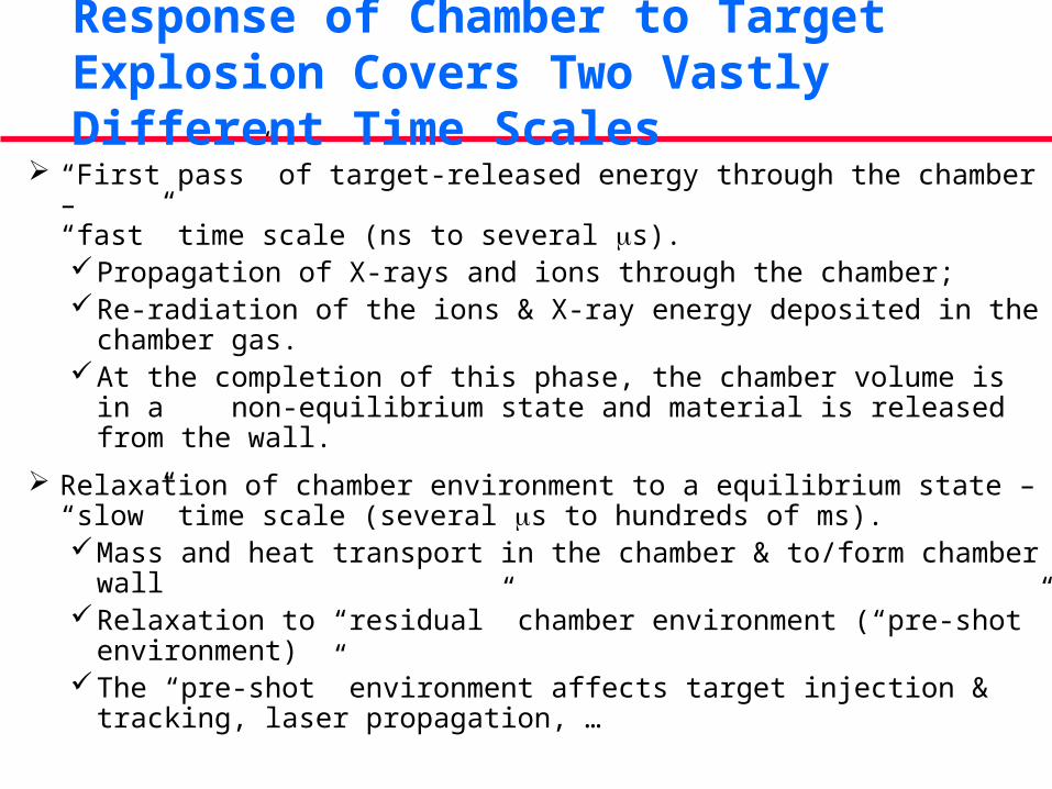
“First pass” of target-released energy through the chamber – “fast” time scale (ns to several s).
Propagation of X-rays and ions through the chamber;Re-radiation of the ions & X-ray energy deposited in the chamber
gas.At the completion of this phase, the chamber volume is in a
non-equilibrium state and material is released from the wall.
Relaxation of chamber environment to a equilibrium state – “slow” time scale (several s to hundreds of ms).
Mass and heat transport in the chamber & to/form chamber wallRelaxation to “residual” chamber environment (“pre-shot”
environment)The “pre-shot” environment affects target injection & tracking,
laser propagation, …
Response of Chamber to Target Explosion Covers Two Vastly Different Time Scales

Multi-Physics Model of Chamber Dynamics
ChamberTarget Wall
Momentum Conservation
Impulse
Energy ConservationPhasechange
Conduction
ImpulsePressure (T)
Pressure(density)
Mass Conservation(multi-phase, multi-species)
Evaporation,sputtering ...
CondensationEvacuation
Energy deposition
Heattransfer Thermal stress
Driver Beams
Energy Input
Momentum Input
Mass Input
Fluidhydrodynamics
Erosion/redeposition
Viscous dissipation
Transport & deposition
Radiation transport
Phase change
Mechanicalresponse
Convection
Eqns. of state
Thermalresponse
Chamber Dynamics Simulation Experiments – Exploration and Planning
Simulation experiments are essential to: Benchmark simulation codes; Ensure all relevant physical phenomena is taken into account
Relatively new field: Previous experimental work focused on shock propagation and/or condensation of wetted chamber walls.
Eventually, we need scaled experiments to screen concepts for implementation on integrated research experiments (IRE’s).
Two major areas need to be investigated first: 1. A source of energy to produce prototypical environments for
experimentation,
2. Experiment characterization and array of diagnostics.

Scaled Simulation Experiments Can Help Address Many Chamber Issues
100–500 J • Large-volume tests for geometrically prototypical testing
1–10 kJ • Integrated (simultaneous) surface and volume effects • Chamber dynamics in limited volume (~1 liter)
1–10 J• Beam propagation and focusing• Near-surface physics• Diagnostic development and experimental techniques
>10 MJ• Integrated prototypical chamber testing
Incl. neutrons

Many Opportunities Exist for International Collaboration
• Design studies
• ARIES-IFE
• Laser driver-chamber interface studies
• Modeling and experiments on optics damage
• Breakdown and beam propagation through chambers
• Chamber dynamic response and clearing R&D
• Numerical modeling
• Simulation experiments