Embed Size (px)
Citation preview
GENERATOR CONTROL AND PROTECTION
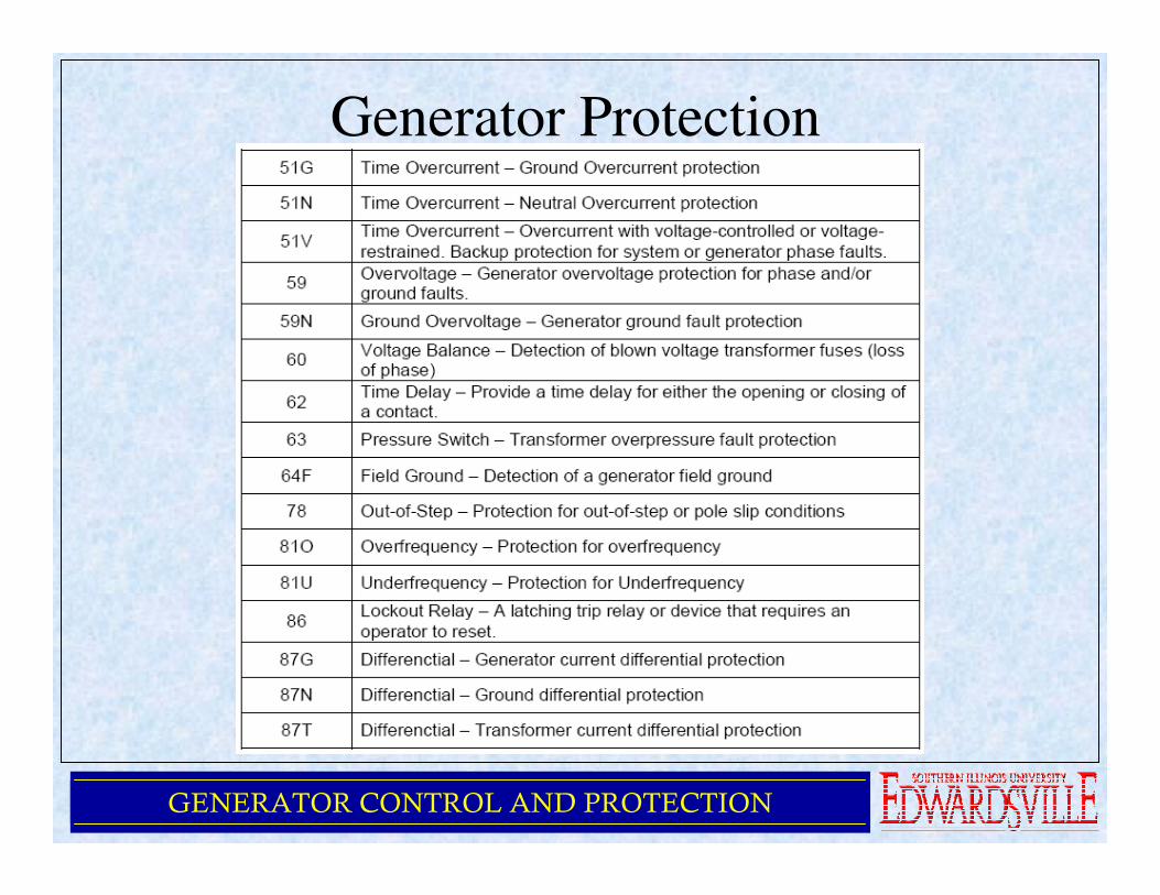
Generator Protection

GENERATOR CONTROL AND PROTECTION
Generator Protection
• Introduction
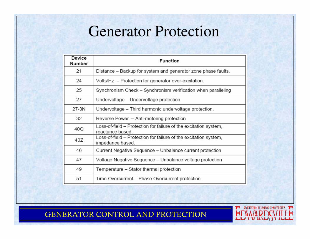
• Device Numbers
• Symmetrical Components
• Fault Current Behavior
• Generator Grounding
• Stator Phase Fault (87G)
• Field Ground Fault (64F)
• Stator Ground Fault (87N, 51N, 59N, 27-3N)

GENERATOR CONTROL AND PROTECTION
Generator Protection
• Loss of Field (40Q, 40Z)
• Over/Under Frequency (81O/81U)
• Overexcitation and Overvoltage (24, 59)
• Out of Step (78)
• Negative Sequence (Current Unbalance) (46)
• Inadvertent Energization (27, 50, 60, 81, 62, 86)
• Loss of Voltage Transformer (60)
• System Backup (51V, 21)
• Conclusion
GENERATOR CONTROL AND PROTECTION
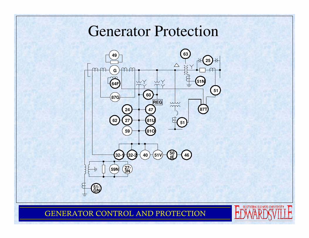
Generator Protection
G
64F
60
51N
87T24
81U
47
2762
87G
59 81O
32-1
59N
51-GN
32-2
27-3N
40 51V50
EI46
6349
REG
51
51
25

GENERATOR CONTROL AND PROTECTION
Steam Generator Stator Windings
GENERATOR CONTROL AND PROTECTION
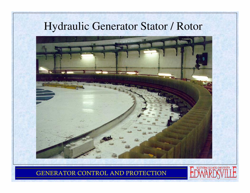
Hydraulic Generator Stator / Rotor

GENERATOR CONTROL AND PROTECTION
Hydraulic Generator Stator Core
GENERATOR CONTROL AND PROTECTION
Generator Protection

GENERATOR CONTROL AND PROTECTION
Split Phase Relaying CT

GENERATOR CONTROL AND PROTECTION
Cylindrical Rotor in Need of Repair
GENERATOR CONTROL AND PROTECTION
Generator Protection
GENERATOR CONTROL AND PROTECTION
Generator Protection

GENERATOR CONTROL AND PROTECTION
Symmetrical Components
• Positive Sequence
– A set of three phasors that have the same magnitude, are equallydisplaced from each other by 120º, and have the same phase sequence as the system under study (ex ABC)
• Negative Sequence– A set of three phasors that have the same magnitude, are equally
displaced from each other by 120º, and have the opposite phase sequence as the system under study (ex ACB)
• Zero Sequence
– A set of three phasors of equal magnitude that are all in phase or have zero displacement from each other

GENERATOR CONTROL AND PROTECTION
Symmetrical Components

GENERATOR CONTROL AND PROTECTION
Symmetrical Components

GENERATOR CONTROL AND PROTECTION
Symmetrical Components

GENERATOR CONTROL AND PROTECTION
Symmetrical Components

GENERATOR CONTROL AND PROTECTION
Symmetrical Components
GENERATOR CONTROL AND PROTECTION
Symmetrical Components
Example Problem
• One conductor of a three phase line is
open. The current flowing to the delta
connected load thru line a is 10A. With
the current in line a as reference and
assuming that line c is open, find the
symmetrical components of the line
currents.
GENERATOR CONTROL AND PROTECTION
Symmetrical Components
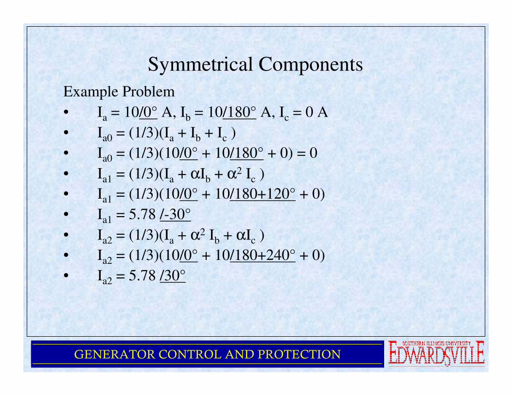
Example Problem
• Ia = 10/0° A, Ib = 10/180° A, Ic = 0 A
• Ia0 = (1/3)(Ia + Ib + Ic )
• Ia0 = (1/3)(10/0° + 10/180° + 0) = 0
• Ia1 = (1/3)(Ia + αIb + α2 Ic )
• Ia1 = (1/3)(10/0° + 10/180+120° + 0)
• Ia1 = 5.78 /-30°
• Ia2 = (1/3)(Ia + α2 Ib + αIc )
• Ia2 = (1/3)(10/0° + 10/180+240° + 0)
• Ia2 = 5.78 /30°

GENERATOR CONTROL AND PROTECTION
Symmetrical Components
Example Problem
• Ib0 = 0
• Ib1 = 5.78 /-150°
• Ib2 = 5.78 /150°
• Ic0 = 0
• Ic1 = 5.78 /90°
• Ic2 = 5.78 /-90°

GENERATOR CONTROL AND PROTECTION
Symmetrical Components
Example Problem
• Ia0 = 0, Ib0 = 0, Ic0 = 0
• Ia1 = 5.78 /-30° , Ib1 = 5.78 /-150° , Ic1 = 5.78 /90°
• Ia2 = 5.78 /30° , Ib2 = 5.78 /150° , Ic2 = 5.78 /-90°

GENERATOR CONTROL AND PROTECTION
Symmetrical Components
Example Problem
• Note: the components Ic1 and Ic2 have
definite values although line c is open and
can carry no net current. As expected, the
sum of these currents is zero.
• The sum of the currents in line a is 10/0°
• The sum of the currents in line b is 10/180°

GENERATOR CONTROL AND PROTECTION
Symmetrical Components
Single Phase Line to Ground Fault

GENERATOR CONTROL AND PROTECTION
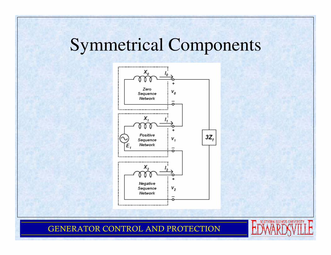
Symmetrical Components
Generator Sequence Networks

GENERATOR CONTROL AND PROTECTION
Symmetrical Components

GENERATOR CONTROL AND PROTECTION
Symmetrical Components
GENERATOR CONTROL AND PROTECTION
Symmetrical Components
GENERATOR CONTROL AND PROTECTION
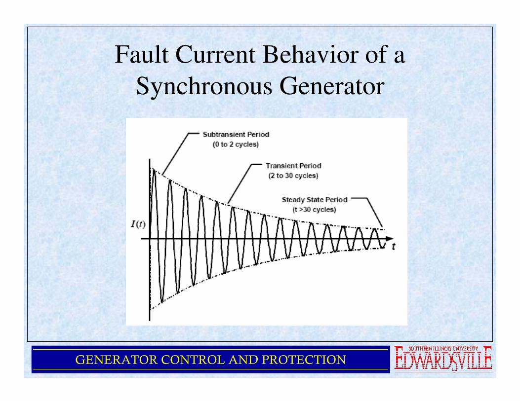
Fault Current Behavior of a
Synchronous Generator
GENERATOR CONTROL AND PROTECTION
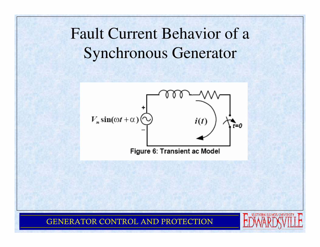
Fault Current Behavior of a
Synchronous Generator

GENERATOR CONTROL AND PROTECTION
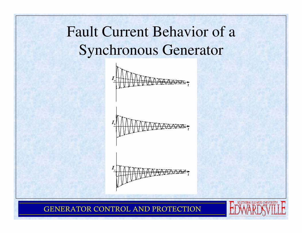
Fault Current Behavior of a
Synchronous Generator
GENERATOR CONTROL AND PROTECTION
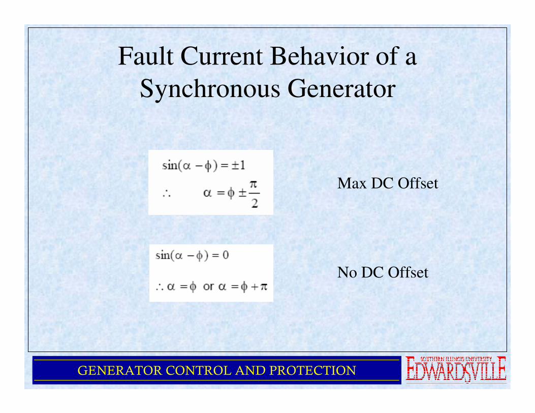
Fault Current Behavior of a
Synchronous Generator
Max DC Offset
No DC Offset
GENERATOR CONTROL AND PROTECTION
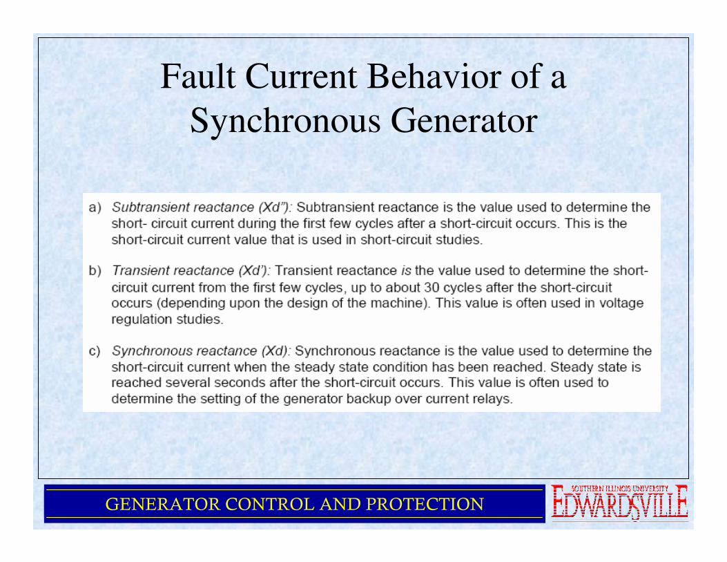
Fault Current Behavior of a
Synchronous Generator
GENERATOR CONTROL AND PROTECTION
Fault Current Behavior of a
Synchronous Generator

GENERATOR CONTROL AND PROTECTION
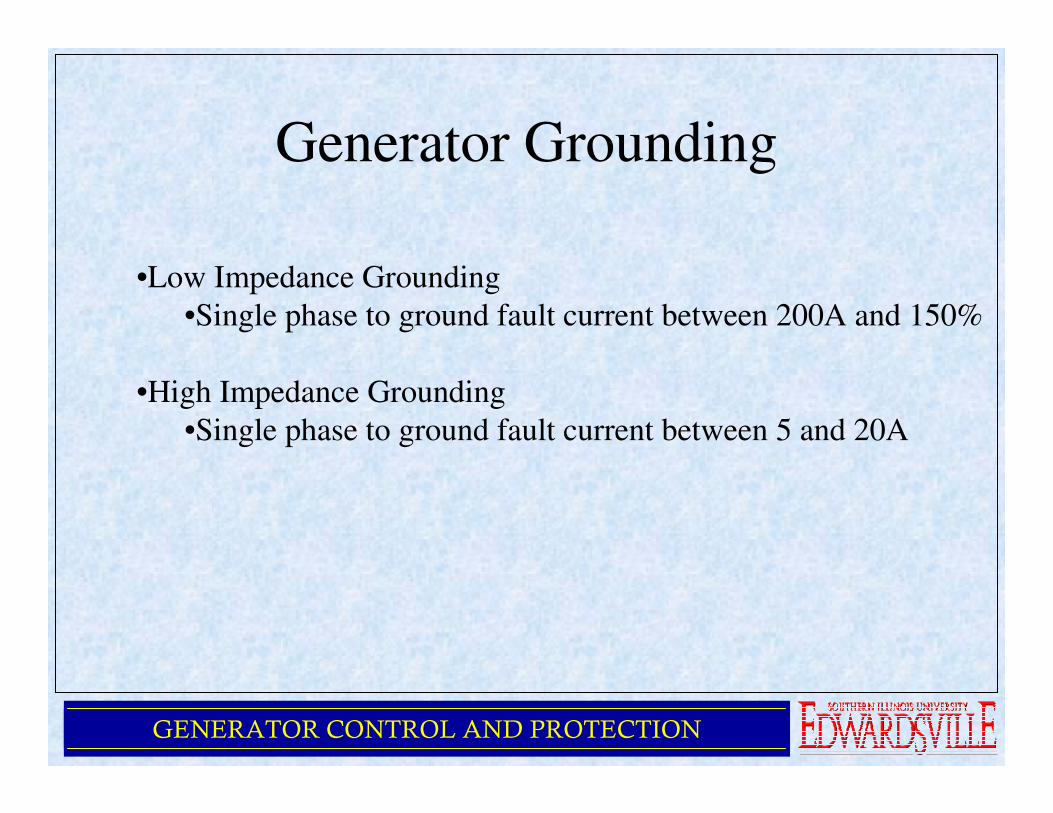
Generator Grounding
GENERATOR CONTROL AND PROTECTION
Generator Grounding
•Low Impedance Grounding
•Single phase to ground fault current between 200A and 150%
•High Impedance Grounding
•Single phase to ground fault current between 5 and 20A
GENERATOR CONTROL AND PROTECTION
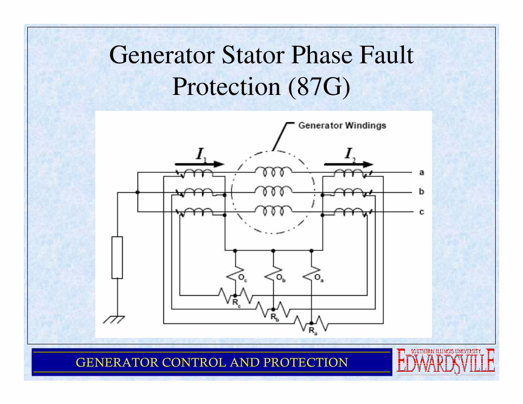
Generator Stator Phase Fault
Protection (87G)
GENERATOR CONTROL AND PROTECTION
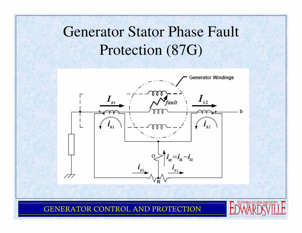
Generator Stator Phase Fault
Protection (87G)
•87G used to protect for:
•3 phase line to line
•1 phase line to line
•multi-phase line to ground
•May not be able to detect a 1 phase to ground fault on high
impedance grounded generators
•Restraint or Percentage Differential Trip Characteristic
•Used to improve sensitivity for detecting small levels of
fault current
•Also maintains security against inadvertent tripping due
to thru faults

GENERATOR CONTROL AND PROTECTION
Generator Stator Phase Fault
Protection (87G)
GENERATOR CONTROL AND PROTECTION
Generator Stator Phase Fault
Protection (87G)

GENERATOR CONTROL AND PROTECTION
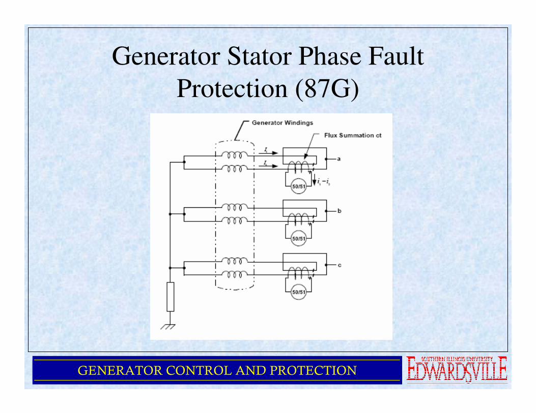
Generator Stator Phase Fault
Protection (87G)
•Split-phase protection scheme
•Able to detect turn-turn faults
•Windings for each phase split into equal groups
•Individual winding currents are vector summed
•Any difference in winding current results in a output from CT
•Overcurrent relay (50/51) can be used to monitor difference
current
•Setting must be above any normal unbalances that may exist
GENERATOR CONTROL AND PROTECTION
Generator Stator Phase Fault
Protection (87G)

GENERATOR CONTROL AND PROTECTION
Generator Field Ground Fault
Protection (64F)

GENERATOR CONTROL AND PROTECTION
Generator Stator Ground Fault
Protection (87N, 51N, 59N & 27-3N)
For Low Impedance Grounded Generators

GENERATOR CONTROL AND PROTECTION
Generator Stator Ground Fault
Protection (87N, 51N, 59N & 27-3N)
For Low Impedance Grounded Generators
GENERATOR CONTROL AND PROTECTION
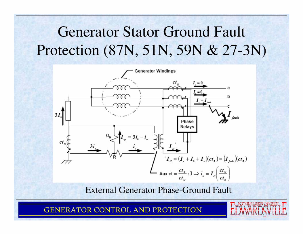
Generator Stator Ground Fault
Protection (87N, 51N, 59N & 27-3N)
External Generator Phase-Ground Fault
GENERATOR CONTROL AND PROTECTION
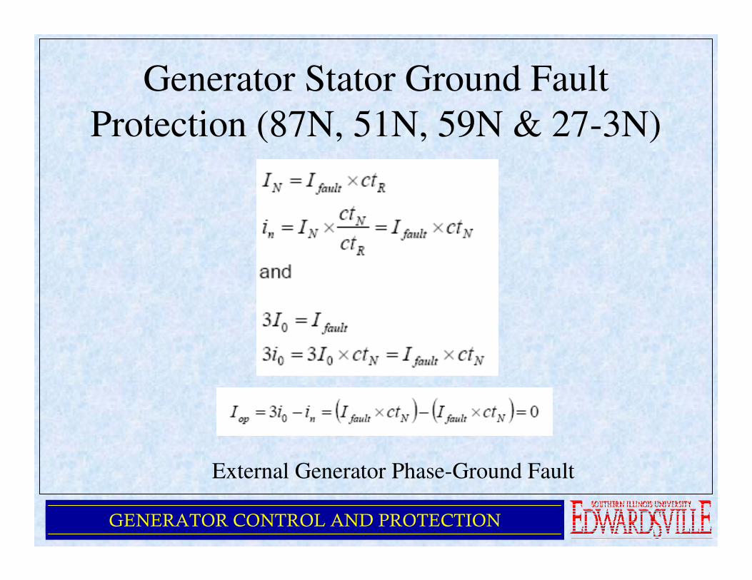
Generator Stator Ground Fault
Protection (87N, 51N, 59N & 27-3N)
External Generator Phase-Ground Fault
GENERATOR CONTROL AND PROTECTION
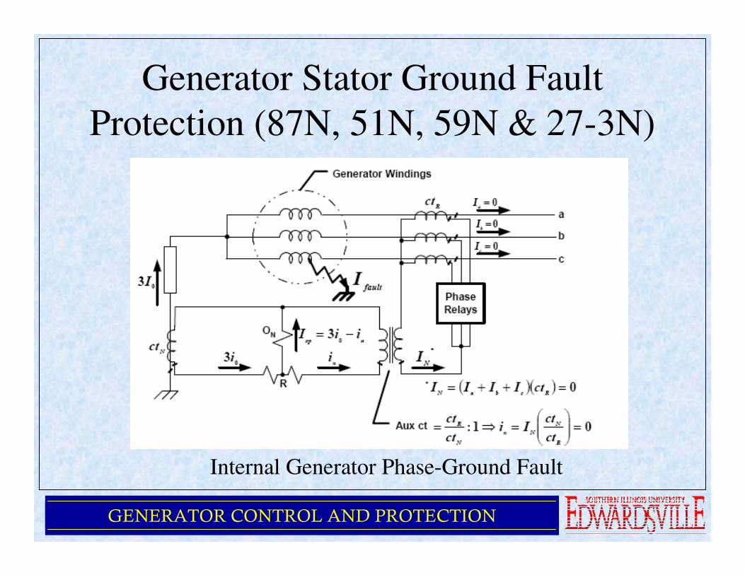
Generator Stator Ground Fault
Protection (87N, 51N, 59N & 27-3N)
Internal Generator Phase-Ground Fault
GENERATOR CONTROL AND PROTECTION
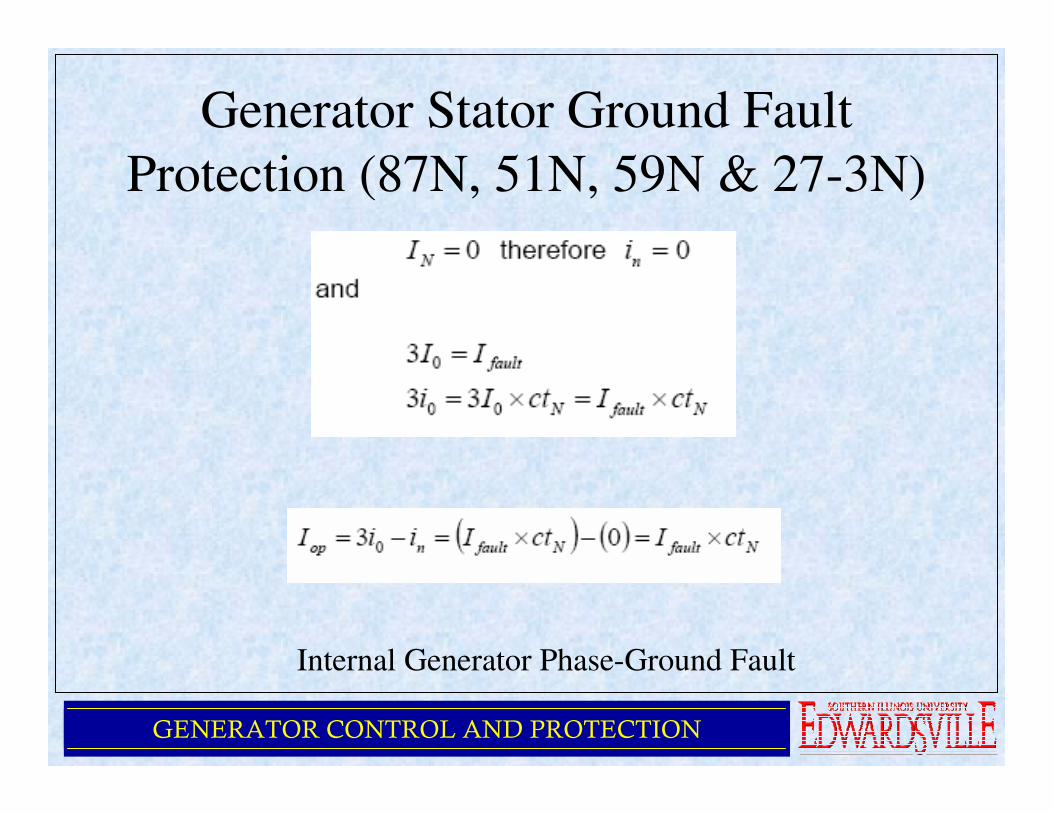
Generator Stator Ground Fault
Protection (87N, 51N, 59N & 27-3N)
Internal Generator Phase-Ground Fault
GENERATOR CONTROL AND PROTECTION
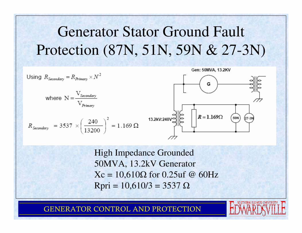
Generator Stator Ground Fault
Protection (87N, 51N, 59N & 27-3N)
High Impedance Grounded
50MVA, 13.2kV Generator
Xc = 10,610Ω for 0.25uf @ 60Hz
Rpri = 10,610/3 = 3537 Ω

GENERATOR CONTROL AND PROTECTION
Loss of Field Protection (40Q, 40Z)

GENERATOR CONTROL AND PROTECTION
Loss of Field Protection (40Q, 40Z)
GENERATOR CONTROL AND PROTECTION
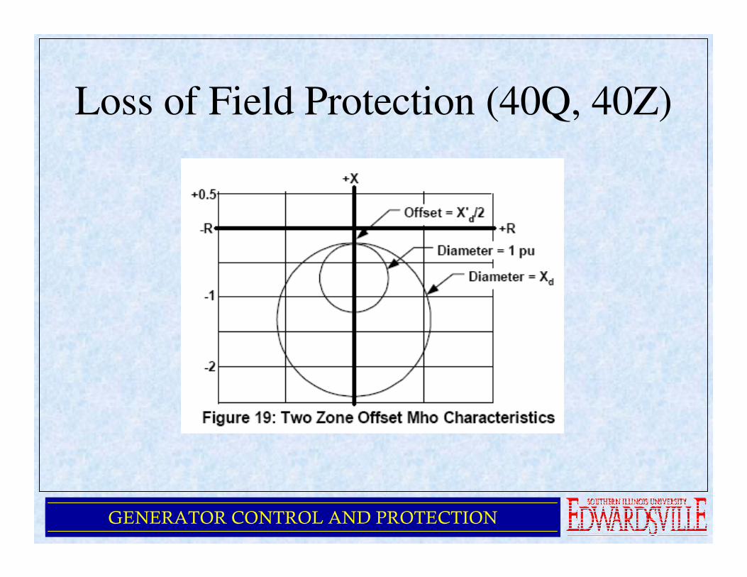
Loss of Field Protection (40Q, 40Z)
GENERATOR CONTROL AND PROTECTION
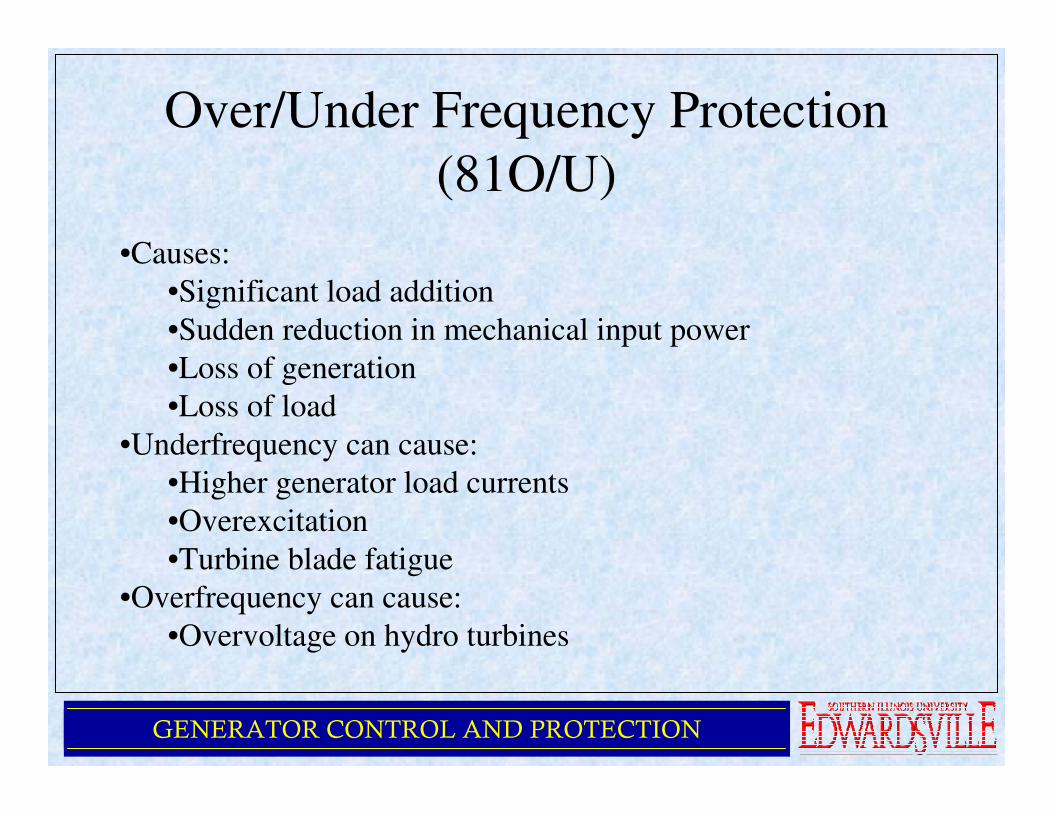
Over/Under Frequency Protection
(81O/U)
•Causes:
•Significant load addition
•Sudden reduction in mechanical input power
•Loss of generation
•Loss of load
•Underfrequency can cause:
•Higher generator load currents
•Overexcitation
•Turbine blade fatigue
•Overfrequency can cause:
•Overvoltage on hydro turbines

GENERATOR CONTROL AND PROTECTION
Overexcitation and Overvoltage
Protection (24, 59)
•Modern Excitation Systems include over excitation limiting
and protection, but it may take several seconds to limit
•Overexcitation occurs when the V/Hz ratio exceeds 105% at
FL and 110% at no load
•V/Hz relays set at 110% with a 5 – 10 sec delay
•Generator overvoltage can occur without exceeding V/Hz
relay setting due to large over speed on hydro generator
•Generator overvoltage relay, 59 may be used
GENERATOR CONTROL AND PROTECTION
Out of Step Protection (78)
•High peak currents and off-frequency operation can occur
when a generator losses synchronism
•Causes winding stress, high rotor iron currents, pulsating
torques and mechanical resonances
•Conventional relaying approach – analyzing variations in
apparent impedance as viewed at generator terminals
•Variation in impedance can be detected by impedance
relaying and generator separated before the completion of one
slip cycle

GENERATOR CONTROL AND PROTECTION
Out of Step Protection (78)
BA
EA EB
ZBZTZA
Generator SystemTransformer
+R
+X
-R
EA/EB>1
Q
P
EA/EB=1
EA/EB<1
ZT
δδδδ
-X
ZA
ZB
A
B

GENERATOR CONTROL AND PROTECTION
Out of Step Protection (78)
R
X
BA
M
B
Element
Pickup
A
Element
Pickup
Blinder
Elements
Mho
Element
Gen X'd
Trans
System
P

GENERATOR CONTROL AND PROTECTION
Negative Sequence Protection (46)
•Protects generator from excessive heating in the rotor due to
unbalanced stator currents
•Negative sequence component of stator current induces
double frequency current in rotor, causing heating
•Rotor temperature rise proportion to I22t
•Negative sequence relays provide settings for this relationship
in the form of a constant, k = I22t
•Minimum permissible continuous unbalance currents are
specified (ANSI/IEEE C50.13)
GENERATOR CONTROL AND PROTECTION
Inadvertent Energization Protection
(27, 50, 60, 81U, 62 and 86)
•Protects against closing of the generator breaker while
machine is not spinning / on turning gear
•Caused by operator error, breaker flash-over, control circuit
malfunction
•Two schemes illustrated:
•Frequency supervised overcurrent
•Voltage supervised overcurrent
GENERATOR CONTROL AND PROTECTION
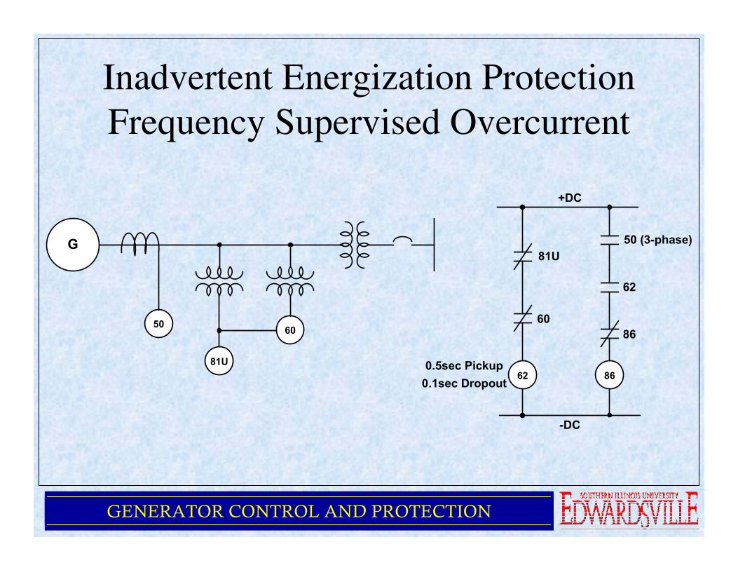
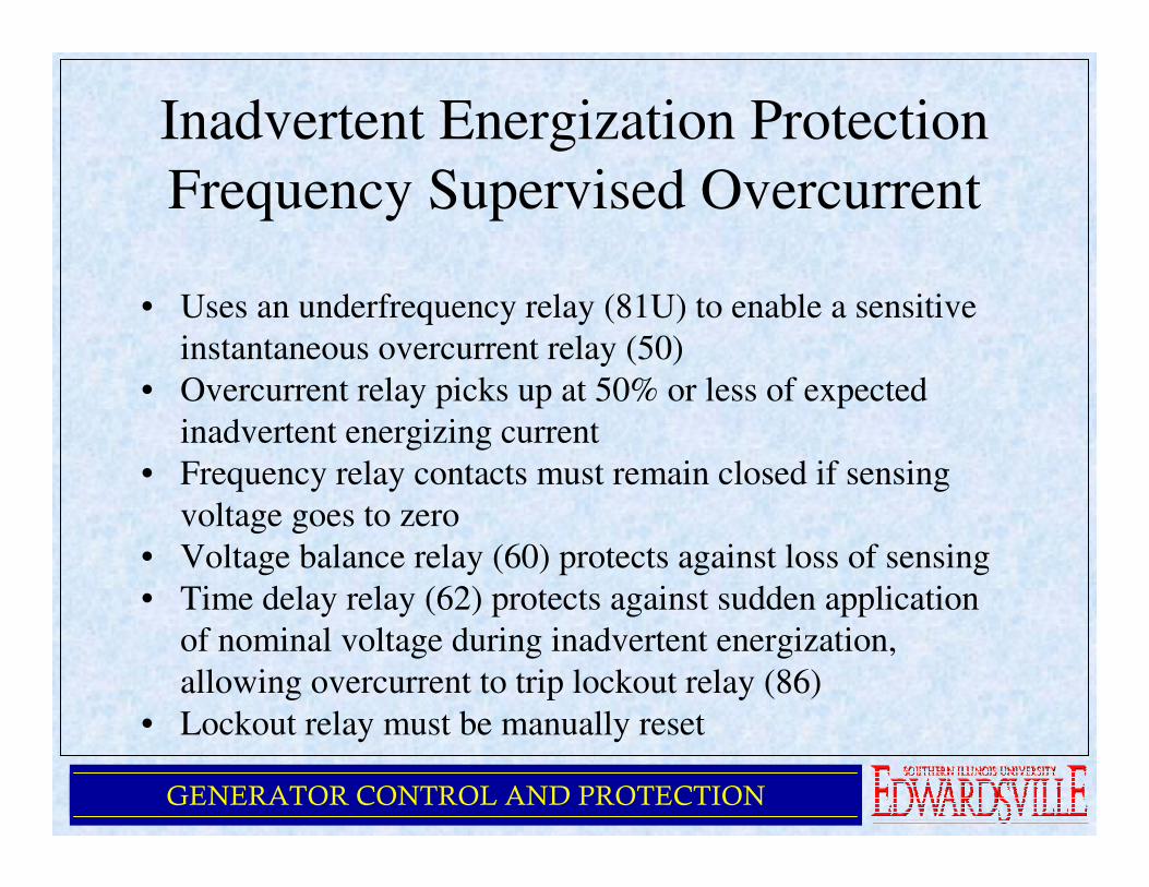
Inadvertent Energization Protection
Frequency Supervised Overcurrent
G
50
81U
60
62
81U
60
86
50 (3-phase)
86
62
+DC
-DC
0.5sec Pickup
0.1sec Dropout
GENERATOR CONTROL AND PROTECTION
Inadvertent Energization Protection
Frequency Supervised Overcurrent
• Uses an underfrequency relay (81U) to enable a sensitive
instantaneous overcurrent relay (50)
• Overcurrent relay picks up at 50% or less of expected
inadvertent energizing current
• Frequency relay contacts must remain closed if sensing
voltage goes to zero
• Voltage balance relay (60) protects against loss of sensing
• Time delay relay (62) protects against sudden application
of nominal voltage during inadvertent energization,
allowing overcurrent to trip lockout relay (86)
• Lockout relay must be manually reset
GENERATOR CONTROL AND PROTECTION
Inadvertent Energization Protection
Voltage Supervised Overcurrent
•Same illustration as frequency supervised overcurrent except
81U replaced by 27
•Undervoltage setpoint of 85% of the lowest expected
emergency operating level

GENERATOR CONTROL AND PROTECTION
Loss of Voltage Transformer
Protection (60)
• Common practice on large systems to use two or more VTs
• One used for relays and metering
• The other used for AVR
• VTs normally fused
• Most common cause of failure is fuse failure
• Loss of VT protection blocks voltage based protective
functions (21, 32, 40 … etc)
• Loss of VT protection measure voltage unbalance, typical
setting is 15%

GENERATOR CONTROL AND PROTECTION
Loss of Voltage Transformer
Protection (60)
G
60
vt
To
Excitation
Controller
To
Protective
Relays

GENERATOR CONTROL AND PROTECTION
System Backup Protection (51V, 21)
• Common practice to provide protection for faults outside
of the generator zone of protection
• Voltage supervised time-overcurrent (51V) or distance
relaying (21) may be used
• Distance relay set to include generator step up transformer
and reach beyond, into the system
• Time delays must be coordinated with those of the system
protection to assure that system protection will operate
before back up
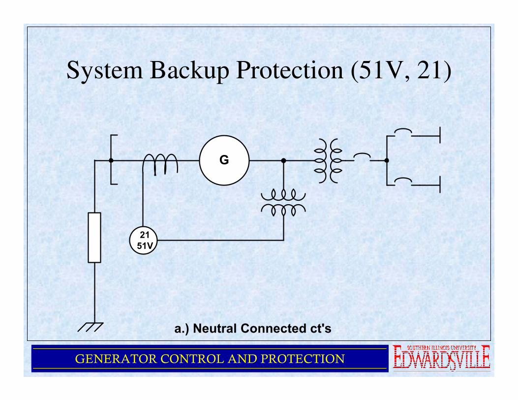
• CTs on neutral side of generator will also provide backup
protection for the generator
GENERATOR CONTROL AND PROTECTION
System Backup Protection (51V, 21)
G
21
51V
a.) Neutral Connected ct's

GENERATOR CONTROL AND PROTECTION
System Backup Protection (51V, 21)
GENERATOR CONTROL AND PROTECTION
System Backup Protection (51V, 21)
• For medium and small sized generators, voltage-restrained
or voltage controlled time overcurrent relays (51V) are
often applied
• Control or restraining function used to prevent or
desensitize the overcurrent relay from tripping until the
generator voltage is reduced by a fault

GENERATOR CONTROL AND PROTECTION
System Backup Protection (51V, 21)
Percent Nominal Volts25% 100%
25%
100%
a.) Voltage-Restrained Overcurrent
Percent Set Value for Pickup
Percent Nominal Volts
Enable
Inhibit
b.) Voltage-Contolled Overcurrent
Pickup Inhibit/Enable
80% 100%
GENERATOR CONTROL AND PROTECTION
Conclusion
• Generators must be protected from electrical faults,
mechanical problem and adverse system conditions
• Some faults require immediate attention (shutdown) while
others just require alarming or transfer to redundant
controllers
• Design of these systems requires extensive understanding
of generator protection
• Further study – IEEE C37.102 Guide for AC Generator
Protective Relaying