Embed Size (px)
Citation preview
A Secure Generator Distance Phase
Backup Protection Setting for Enhancing
Generator Overexcitation Thermal
Capability during System Disturbances
Mohamed Elsamahy Military Technical College, Cairo, Egypt
Sherif Faried
University of Saskatchewan, Saskatoon, SK, Canada
Tarlochan S. Sidhu
University of Ontario Institute of Technology, Oshawa, ON, Canada
Contents
Motivation
Steady State Generator Overexcited Capability (GOEC)
Generator Distance Phase Backup Protection (Relay 21)
Coordination between Relay 21 and GOEC
Overexcitation thermal capability and Overexcitation limiter (OEL)
System Under Study and Simulation Results
Conclusions
2
“Performance of generation protection during major system
disturbances”
• Due to generator protection misoperations during recent blackouts :
1996 outages in the Western U.S.
2003 U.S. East Coast blackout
2007 Saskatchewan mid west disturbance
As a result the need for better coordination of generator protection
with generator capability and control has come to light.
Motivation
• Therefore, NERC has mandated several tests and is asking users to
verify the coordination between generator protection and control.
3
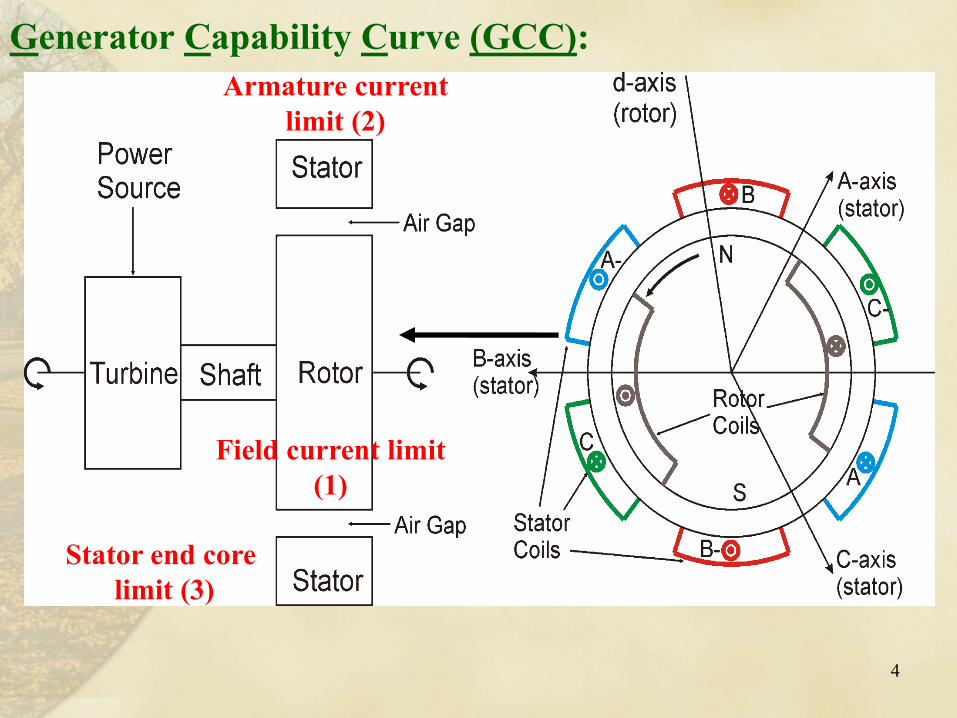
Field current limit
(1)
Armature current
limit (2)
Stator end core
limit (3)
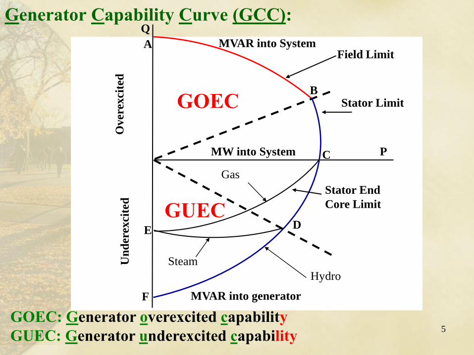
Generator Capability Curve (GCC):
4
P C
Hydro
Steam
Gas
D
A
Un
der
excit
ed
O
vere
xcit
ed
E
B
Field Limit
MW into System
Stator Limit
Stator End
Core Limit
F
MVAR into System
MVAR into generator
Q Generator Capability Curve (GCC):
5
GOEC
GUEC
GOEC: Generator overexcited capability
GUEC: Generator underexcited capability
6
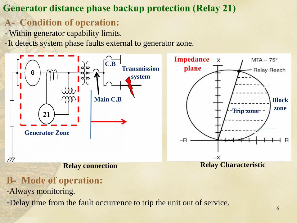
A- Condition of operation: - Within generator capability limits.
- It detects system phase faults external to generator zone.
B- Mode of operation: -Always monitoring.
-Delay time from the fault occurrence to trip the unit out of service.
Block
zone Trip zone
Impedance
plane
Relay Characteristic
21
Main C.B
Transmission
system
C.B
Generator distance phase backup protection (Relay 21)
Generator Zone
Relay connection
7
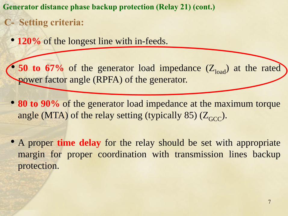
• 120% of the longest line with in-feeds.
Generator distance phase backup protection (Relay 21) (cont.)
C- Setting criteria:
• 80 to 90% of the generator load impedance at the maximum torque
angle (MTA) of the relay setting (typically 85) (ZGCC).
• 50 to 67% of the generator load impedance (Zload) at the rated
power factor angle (RPFA) of the generator.
• A proper time delay for the relay should be set with appropriate
margin for proper coordination with transmission lines backup
protection.
8
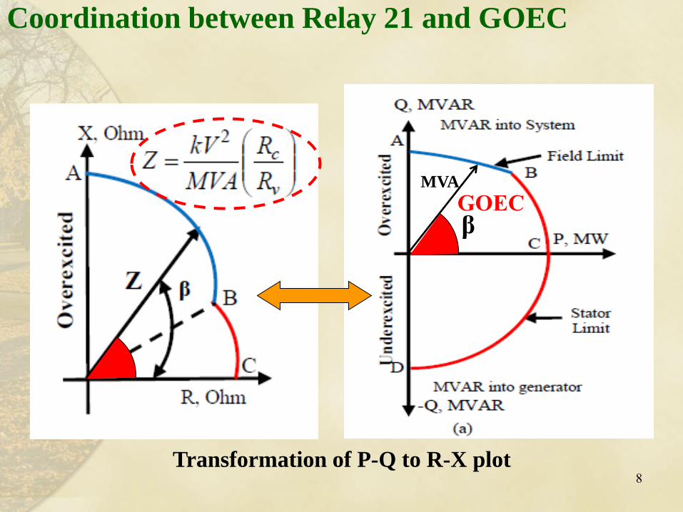
Coordination between Relay 21 and GOEC
Transformation of P-Q to R-X plot
MVA
β GOEC
9
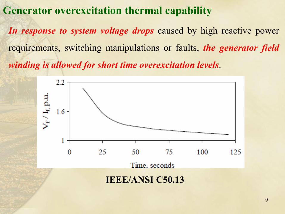
In response to system voltage drops caused by high reactive power
requirements, switching manipulations or faults, the generator field
winding is allowed for short time overexcitation levels.
Generator overexcitation thermal capability
IEEE/ANSI C50.13
10
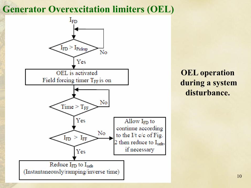
Generator Overexcitation limiters (OEL)
OEL operation
during a system
disturbance.
G 21
A
∞
B
Hydro
Generator Infinite
Bus
230 kV, 300 km
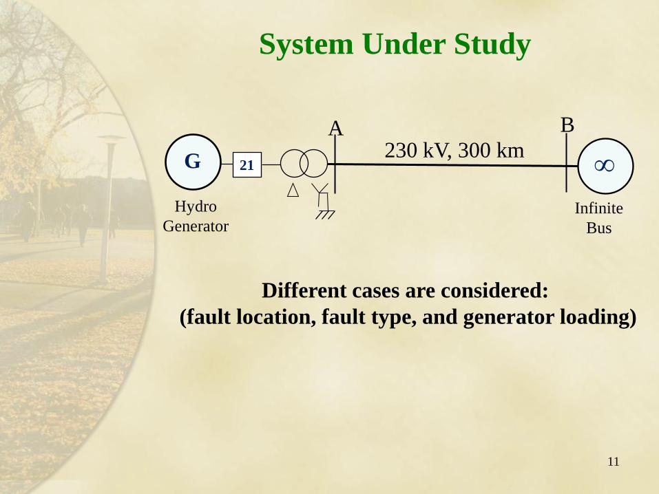
Different cases are considered:
(fault location, fault type, and generator loading)
System Under Study
11
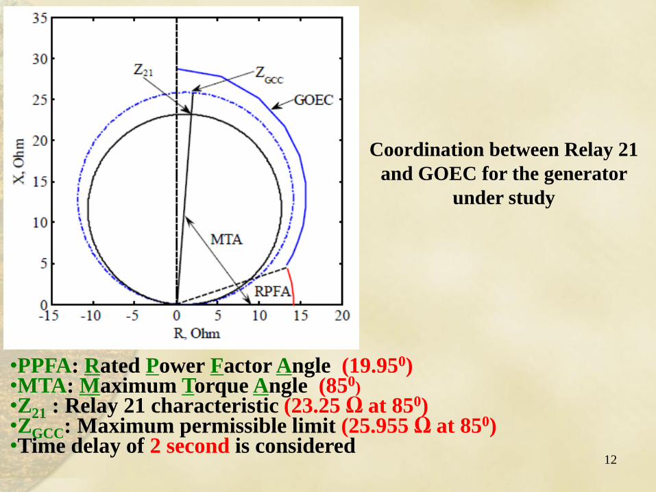
Coordination between Relay 21
and GOEC for the generator
under study
•PPFA: Rated Power Factor Angle (19.950) •MTA: Maximum Torque Angle (850)
•Z21 : Relay 21 characteristic (23.25 Ω at 850) •ZGCC: Maximum permissible limit (25.955 Ω at 850) •Time delay of 2 second is considered
12
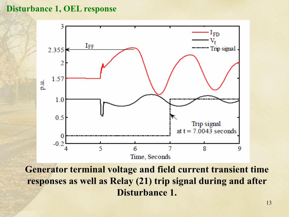
Disturbance 1, OEL response
13
Generator terminal voltage and field current transient time
responses as well as Relay (21) trip signal during and after
Disturbance 1.
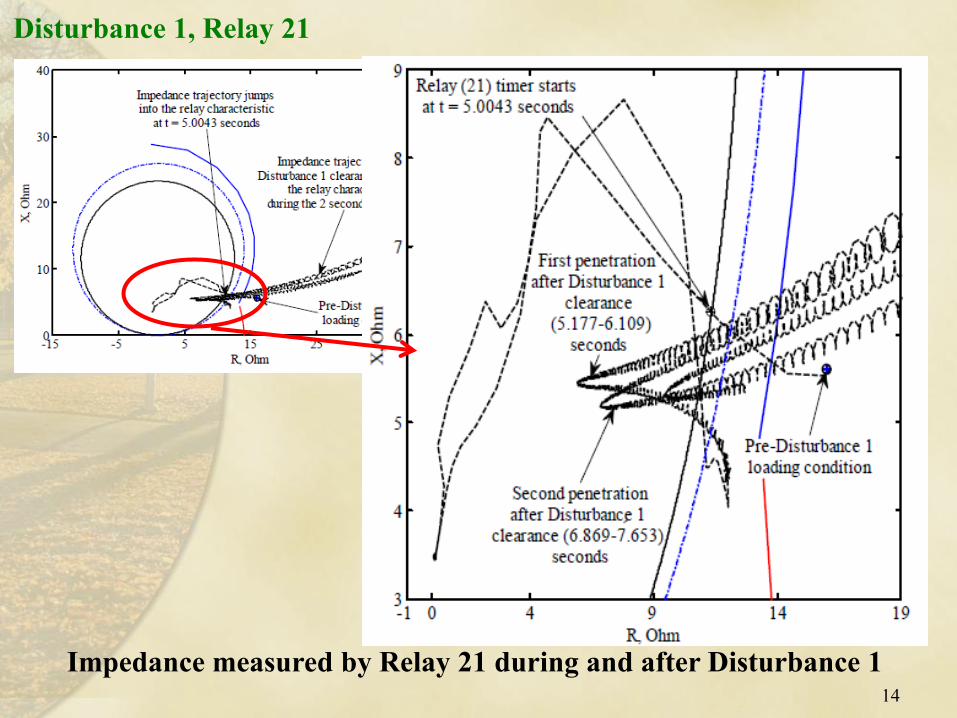
Impedance measured by Relay 21 during and after Disturbance 1 14
Disturbance 1, Relay 21
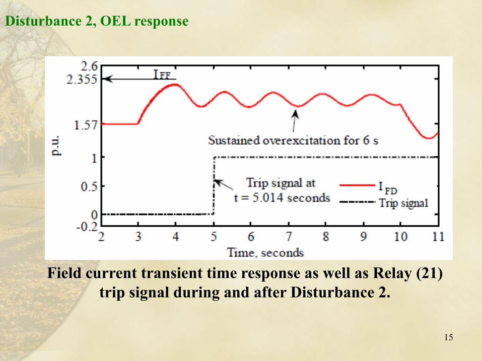
Disturbance 2, OEL response
15
Field current transient time response as well as Relay (21)
trip signal during and after Disturbance 2.
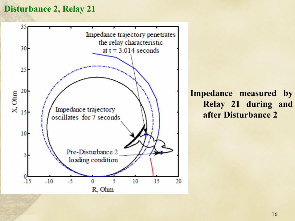
Impedance measured by
Relay 21 during and
after Disturbance 2
16
Disturbance 2, Relay 21
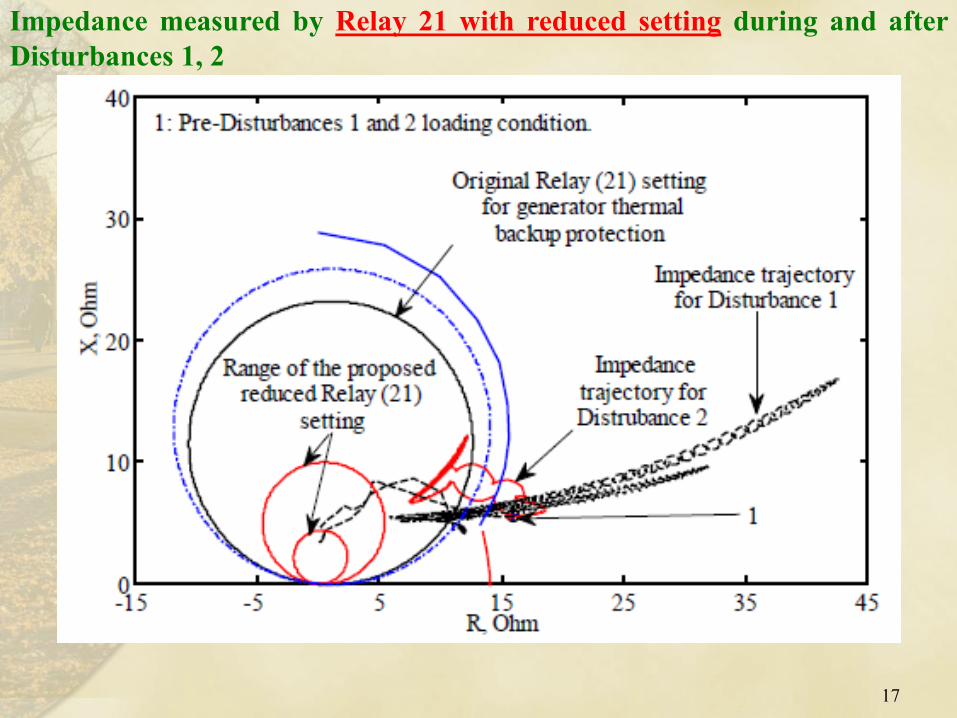
Impedance measured by Relay 21 with reduced setting during and after
Disturbances 1, 2
17
• The current setting of Relay (21) for generator thermal backup
protection restricts the overexcitation thermal capability of the
generator
Conclusions
18
• Such a restriction does not allow the generator to supply its
maximum reactive power during system disturbances.
• The paper highlights the need for revising the setting of the Relay
(21) through in-depth dynamic stability studies in order to allow
the generator to fulfill the system requirements during major
disturbances to ensure adequate level of voltage stability
• In this regard, the paper proposes the reduction of Relay (21) reach
19
THANK YOU
For further information, please contact
Dr. Mohamed Elsamahy, P.Eng.
Department of Electrical Power & Energy
Military Technical College, Cairo, Egypt