Embed Size (px)
Citation preview

Training Systems for Electrical Power Engineering The Complete Power Supply Network with Renewable Energies
3rd Edition
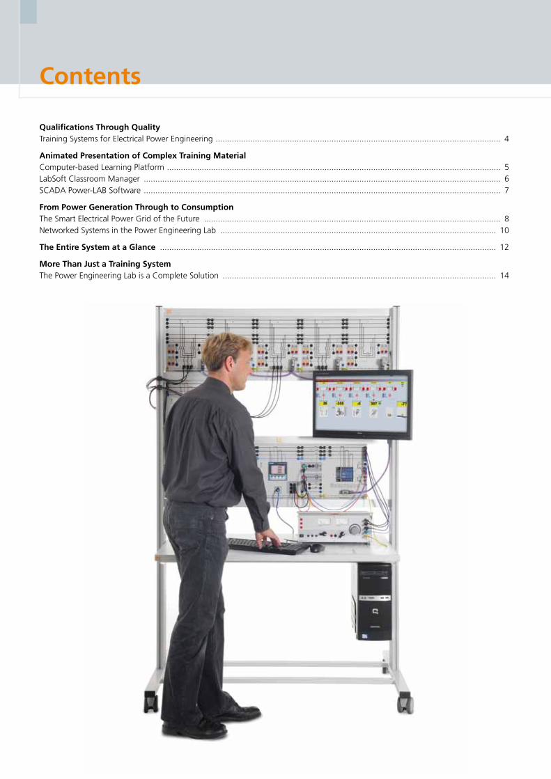
Contents
Qualifications Through Quality Training Systems for Electrical Power Engineering ........................................................................................................................... 4
Animated Presentation of Complex Training Material Computer-based Learning Platform ................................................................................................................................................ 5 LabSoft Classroom Manager .......................................................................................................................................................... 6 SCADA Power-LAB Software .......................................................................................................................................................... 7
From Power Generation Through to Consumption The Smart Electrical Power Grid of the Future ................................................................................................................................ 8Networked Systems in the Power Engineering Lab ....................................................................................................................... 10
The Entire System at a Glance ................................................................................................................................................. 12
More Than Just a Training System The Power Engineering Lab is a Complete Solution ...................................................................................................................... 14

Contents
Fundamentals of Power Engineering ...................................................................................................................................... 16DC, AC and Three-phase Technology (UniTrain-I) .......................................................................................................................... 20Magnetism/Electromagnetism (UniTrain-I) ..................................................................................................................................... 23Measurements with the Multimeter (UniTrain-I) ............................................................................................................................ 24Power Grids and Grid Models (UniTrain-I) ..................................................................................................................................... 25Current and Voltage Transformers ................................................................................................................................................ 26
Power Generation ..................................................................................................................................................................... 28Synchronous Machines (UniTrain-I) ............................................................................................................................................... 32Automatic Generator Control and Synchronisation ....................................................................................................................... 33 Generator Protection ................................................................................................................................................................... 35
Renewable Power Generation ................................................................................................................................................. 38Photovoltaics (UniTrain-I) .............................................................................................................................................................. 42Advanced Photovoltaics ................................................................................................................................................................ 44Wind Power Plants ........................................................................................................................................................................ 48Fuel Cell Technology (UniTrain-I) ................................................................................................................................................... 54Advanced Fuel Cell Technology .................................................................................................................................................... 56
Transformers .............................................................................................................................................................................. 58Three-phase Transformers (UniTrain-I) ........................................................................................................................................... 62Investigating Transformers ............................................................................................................................................................ 63Transformer Protection ................................................................................................................................................................. 64
Power Transmission .................................................................................................................................................................. 66Investigations on Three-phase Transmission Lines ......................................................................................................................... 70 Transmission Line with Earth-fault Compensation ......................................................................................................................... 72Transmission Systems with a Synchronous Generator ................................................................................................................... 73 Transmission Lines ........................................................................................................................................................................ 74Line Protection ............................................................................................................................................................................. 76
Power Distribution .................................................................................................................................................................... 80 Three-phase Double Busbar System .............................................................................................................................................. 84Overcurrent Protection for Double ................................................................................................................................................ 85
Power management ................................................................................................................................................................. 86 Complex Loads, Power Consumption Metering and Peak Load Monitoring ................................................................................... 90Dynamic Loads .............................................................................................................................................................................. 91 Manual and Automatic Compensation of Reactive Power ............................................................................................................. 92Energy-efficient drives ................................................................................................................................................................... 93Protection of Electric Loads .......................................................................................................................................................... 94
Smart Grid ................................................................................................................................................................................. 96 Smart Grid: Control Centre ......................................................................................................................................................... 102Smart Grid: Energy Management ................................................................................................................................................ 103 Energy Generators in a Smart Grid .............................................................................................................................................. 104Energy Storage Facilities in a Smart Grid ...................................................................................................................................... 105
Qualifications Through Quality
Training Systems for Electrical Power Engineering
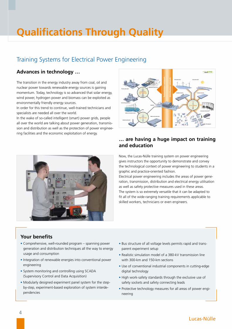
Advances in technology …
The transition in the energy industry away from coal, oil and
nuclear power towards renewable energy sources is gaining
momentum. Today, technology is so advanced that solar energy,
wind power, hydrogen power and biomass can be exploited as
environmentally friendly energy sources.
In order for this trend to continue, well-trained technicians and
specialists are needed all over the world.
In the wake of so-called intelligent (smart) power grids, people
all over the world are talking about power generation, transmis-
sion and distribution as well as the protection of power enginee-
ring facilities and the economic exploitation of energy.
… are having a huge impact on training and education
Now, the Lucas-Nülle training system on power engineering
gives instructors the opportunity to demonstrate and convey
the technological context of power engineering to students in a
graphic and practice-oriented fashion.
Electrical power engineering includes the areas of power gene-
ration, transmission, distribution and electrical energy utilisation
as well as safety protective measures used in these areas.
The system is so extremely versatile that it can be adapted to
fit all of the wide-ranging training requirements applicable to
skilled workers, technicians or even engineers.
Your benefits • Comprehensive, well-rounded program – spanning power
generation and distribution techniques all the way to energy
usage and consumption
• Integration of renewable energies into conventional power
engineering
• System monitoring and controlling using SCADA
(Supervisory Control and Data Acquisition)
• Modularly designed experiment panel system for the step-
by-step, experiment-based exploration of system interde-
pendencies
• Bus structure of all voltage levels permits rapid and trans-
parent experiment setup
• Realistic simulation model of a 380-kV transmission line
with 300-km and 150-km sections
• Use of conventional industrial components in cutting-edge
digital technology
• High work-safety standards through the exclusive use of
safety sockets and safety connecting leads
• Protective technology measures for all areas of power engi-
neering
4Lucas-Nülle

Computer-based Learning Platform - Interactive Lab Assistant (ILA)
Animated Presentation of Complex Training Contents
Your benefits• Theory conveyed using easily understood animations
• Support whilst carrying out experiments
• Interactive display of experiment set-ups
• Access to actual measuring instruments and testers with extensive evaluation capabilities
• Practically oriented project exercises to perfect successful learning
• Integrated operating instructions
• Documentation of experiment results (creation of an experiment report)
• Knowledge tests including feedback function
• Includes SCADA Viewer software with appropriate measuring exercises
Interactive Lab Assistant (ILA) gives you all the support you need for carrying out experiments. It not only provides instructions, it also
supplies valuable theoretical information, records measurements and automatically creates the necessary laboratory documentation
in the background in the form of a printable document or a PDF file. If you want to change the experiment instructions, you can
simply use Labsoft Classroom Manager to modify or add content.
5Lucas-Nülle

Animated Presentationof Complex Training Contents
LabSoft Classroom Manager
LabSoft Classroom Manager is an administration software package with extensive functionality. It allows practically oriented training
and learning processes to be organised and managed in comfort. Classroom Manager is suitable for all LabSoft-based training pro-
grams, such as ILA, UniTrain-I, InsTrain and CarTrain. It consists of the following sub-programs:
LabSoft Manager: Manage your LabSoft courses, students and student work groups with LabSoft Manager. Then students can always be provided with the best training content for their needs.
LabSoft Reporter: Learning progress and test results can be presented for analysis by means of LabSoft Reporter. Targeted monitoring allows for multiple ways of evaluating individual or group results from courses or tests.
LabSoft Test Creator: LabSoft TestCreator is for creating tests, with which knowledge and practical skills can be examined at the same time.
LabSoft Editor: LabSoft Editor allows you to create new courses or make changes to existing ones. Numerous wizards are available to guide users step by step through the necessary settings
LabSoft Questioner: In order to create individual questions, measuring exercises or test exercises, LabSoft Questioner provides a host of question templates. Tasks and questions can then be introduced into actual courses.
Question and answer database for renewable energies
6Lucas-Nülle

Power-LAB-Software
By Supervisory Control and Data Acquisition (SCADA), we mean the monitoring, control and data acquisition of technical processes
as they happen in real time. In electrical power engineering, SCADA is used to cover the entire spectrum from power generation,
transmission – including protection measures – to power utilisation. SCADA provides technicians with the opportunity of tracking
and entering data into these processes. Measurement values are displayed on the screen in real time. Control signals can be modified
during these processes. The SCADA system can also control these processes automatically. The recording of so many measurement
values permits not only better future planning but also economic optimisation. The system can also be remotely controlled using
local access networks (LAN). SCADA is the key component in a smart grid, which leads to better use of mains power infrastructure
and energy reserves.
Your benefits• SCADA software adapted for training and education
• Implementation, control and analysis of complex, intelligent
grids (smart grids)
• SCADA Designer: - Symbolic layout of all equipment from Lucas-Nülle’s power
engineering range on a user interface
- Standardised electronic circuit symbols
• SCADA Viewer: - School licence for observation and control of systems
- Display and control of measurements and status from all
computers on the network
- Key parameters and signals can be controlled by software
• SCADA PLC: Integrated software PLC, programmable in
compliance with IEC 61131
• SCADA Logger: Recording, display, evaluation and export
of all values recorded in a given period
• SCADA Panel Designer: Design your own control panels
• SCADA Net: - The client/server concept makes it possible to remotely
access systems on the smart grid from multiple
student PCs at the same time.
- Access can be configured to be limited or unlimited by
teachers using the SCADA software
SCADA
7 Lucas-Nülle
From Power Generation Through to Consumption
Extremely high voltage
High voltage
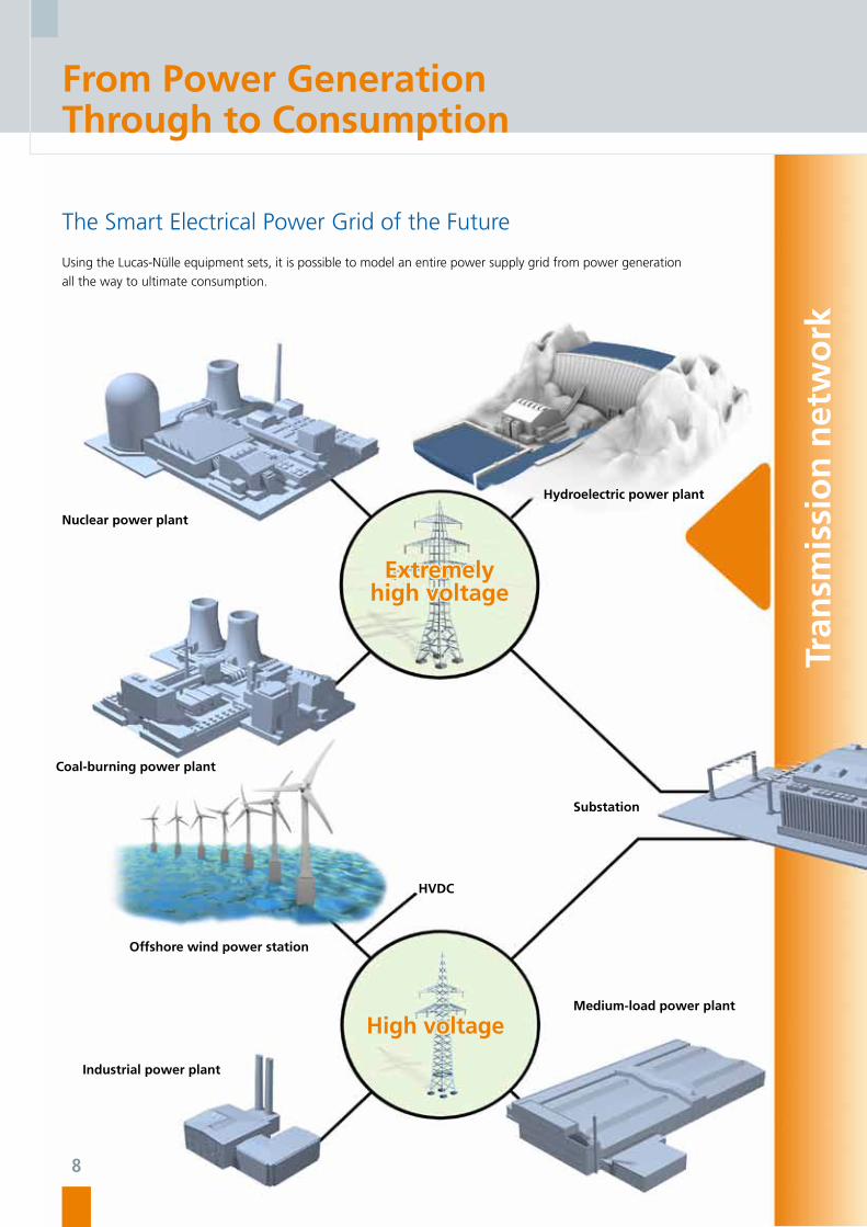
The Smart Electrical Power Grid of the Future
Using the Lucas-Nülle equipment sets, it is possible to model an entire power supply grid from power generation
all the way to ultimate consumption.
Nuclear power plant
Coal-burning power plant
Offshore wind power station
Industrial power plant
Medium-load power plant
Substation
Hydroelectric power plant
Tran
smis
sio
n n
etw
ork
HVDC
8

Low voltage
Dis
trib
uti
on
net
wo
rk
11001010
Wind power plant Solar power plant
Smart-grid control centre
Municipal grid
Local grid
Industrial consumer Industrial consumer
E-Mobility
You can find more on the topic of smart grids from page 96 onwards
9

10010101010111010101010101111010000010101010100010101110101010100010010001001010101001001010100101011100010101010100010101010000101001010010010000100101000101010101
From Power Generation Through to Consumption
Lucas-Nülle
Networked Systems in the Power Engineering Laboratory
The smart lab The power engineering equipment sets from Lucas-Nülle GmbH can be combined with each other as required. Accordingly, you can,
for example, take the power obtained from renewable energy sources and transmit this power via a line model, use a transformer
to step it up or down and distribute it to any number of consumers using the double busbar. Additionally, the bus systems of the
measurement and protective equipment can all be interconnected, centrally evaluated and controlled using SCADA for Power-LAB
software. Accordingly, all of the obstacles to the design and investigation of intelligent power grids in the lab have been overcome.
Generation
10

10010101010111010101010101111010000010101010100010101110101010100010010001001010101001001010100101011100010101010100010101010000101001010010010000100101000101010101
Lucas-Nülle
Transmission Distribution Consumption
You can find more on the topic of smart grids from page 96 onwards
11

The Entire System at a Glance
Generator protection
• Generator-differential protection • Overcurrent time protection • Unbalanced load protection • Reverse-power protection • Over/undervoltage protection • Stator-earth fault protection • Rotor-earth fault protection
Line protection
• Over/undervoltage protection • Directional protection • Overcurrent time protection • Earth-fault protection • Protection of parallel lines • Distance protection
Busbar protection
• Overcurrent protection for double busbars
Protection for electrical loads
• Protection for electrical machines • Motor management relays
Transformer protection
• Transformer-differential protection • Time overcurrent protection
SCADA SCADA SCADA SCADA SCADA
SCADA SCADA SCADA SCADA SCADA
Protection of power engineering facilities
Investigations on power engineering facilities
Fundamentals of electrical engineering
EGP
Power generation
• Three-phase synchronous generators • Synchronisation circuits • Automatic power factor and power control
Renewable power generation
• Wind power • Photovoltaics • Fuel cells
EUG
Transformers
• Transformer operating at no-load and with short circuit • Transformer with ohmic, inductive and capacitive load • Parallel operation of transformers • Current distribution for various vector groups
EUT
Power transmission
• Investigations on three-phase lines• Investigations on parallel lines • Investigations on lines with earth-fault compensation • Investigations on transmission systems with synchronous generator
EUL
Power distribution
• Three-phase double busbar system • Manually operated busbar change • Automatic busbar change with PC
EPD
Power consumption
• Complex loads • Reactive power compensation • Power consumption measurement • Peak load monitoring • Energy management
EUC
ETP ELP EDP ECP
Current and voltage transformers
• Current transformer for protective equipment• Voltage transformer for protective equipment
EUB
Basics of electrical engineering
• DC technology• AC technology• Three-phase technology• Magnetism/electromagnetism• Measurements with the multimeter
Power grids and grid models
• Transient processes in DC and AC grids• DC power grids
Smart grid
• Renewable Energies in a Smart Grid • Combination and constrol of all systems• SCADA Software• Intelligent energy management: coordination of energy generation and consumption
12Lucas-Nülle

Generator protection
• Generator-differential protection • Overcurrent time protection • Unbalanced load protection • Reverse-power protection • Over/undervoltage protection • Stator-earth fault protection • Rotor-earth fault protection
Line protection
• Over/undervoltage protection • Directional protection • Overcurrent time protection • Earth-fault protection • Protection of parallel lines • Distance protection
Busbar protection
• Overcurrent protection for double busbars
Protection for electrical loads
• Protection for electrical machines • Motor management relays
Transformer protection
• Transformer-differential protection • Time overcurrent protection
SCADA SCADA SCADA SCADA SCADA
SCADA SCADA SCADA SCADA SCADA
Protection of power engineering facilities
Investigations on power engineering facilities
Fundamentals of electrical engineering
EGP
Power generation
• Three-phase synchronous generators • Synchronisation circuits • Automatic power factor and power control
Renewable power generation
• Wind power • Photovoltaics • Fuel cells
EUG
Transformers
• Transformer operating at no-load and with short circuit • Transformer with ohmic, inductive and capacitive load • Parallel operation of transformers • Current distribution for various vector groups
EUT
Power transmission
• Investigations on three-phase lines• Investigations on parallel lines • Investigations on lines with earth-fault compensation • Investigations on transmission systems with synchronous generator
EUL
Power distribution
• Three-phase double busbar system • Manually operated busbar change • Automatic busbar change with PC
EPD
Power consumption
• Complex loads • Reactive power compensation • Power consumption measurement • Peak load monitoring • Energy management
EUC
ETP ELP EDP ECP
Current and voltage transformers
• Current transformer for protective equipment• Voltage transformer for protective equipment
EUB
Basics of electrical engineering
• DC technology• AC technology• Three-phase technology• Magnetism/electromagnetism• Measurements with the multimeter
Power grids and grid models
• Transient processes in DC and AC grids• DC power grids
Smart grid
• Renewable Energies in a Smart Grid • Combination and constrol of all systems• SCADA Software• Intelligent energy management: coordination of energy generation and consumption
10
01
01
01
01
01
11
01
01
01
01
01
01
11
10
10
00
00
10
10
10
10
10
00
10
10
11
10
10
10
10
10
00
10
01
00
01
00
10
10
10
10
01
00
10
10
10
01
01
01
11
00
01
01
01
01
01
00
01
01
01
01
00
00
10
10
01
01
00
10
01
00
00
10
01
01
00
01
01
01
01
01
13 Lucas-Nülle

The Power Engineering Lab is a Complete Solution
More Than Just a Training System
Modern training media are used to graphically present complex learning material
Renewable energies: Wind power, fuel cells, photovoltaics
14Lucas-Nülle

”Smart grid“: monitor, measure and control the entire power flow using the SCADA system
Complete solutions for electrical power engineering: from power generation, transmission and distribution through to consumption – it‘s all covered.
Multimedia-based transfer of know-how using UniTrain-I
15 Lucas-Nülle


Fundamentals of Power Engineering
DC Technology (UniTrain-I) ..................................................... 20
AC Technology (UniTrain-I) ..................................................... 21
Three-phase Technology (UniTrain-I) ....................................... 22
Magnetism / Electromagnetism (UniTrain-I) ............................. 23
Measurements with the Multimeter (UniTrain-I) ...................... 24
Power Grids and Grid Models (UniTrain-I) ............................... 25
Current and Voltage Transformers .......................................... 26

Fundamentals of Power Engineering
Fundamentals of Power Engineering
Multimedia-based and Practice-oriented Introduction to Power Engineering
Using the multimedia-based experiment and training system UniTrain-I, the student is guided through experiments and theoretical
sections accompanied by clearly structured course software which is enhanced by texts, graphics, animations and progress tests.
In addition to the learning software, the course comes with a set of experiment cards on which practical assignments are performed.
With the aid of numerous experiments and animations, the UniTrain-I multimedia course gives the student insight into the latest
important issues relating to power engineering. The fundamentals of DC, AC and three-phase technology as well as processes in dis-
tribution networks are some of the subjects dealt with in the various courses. Typical processes that occur in the generation and dis-
tribution of electrical power receive particularly close attention and are reproduced in the experiments using safe extra-low voltages.
Your benefits • System trains theory and practice at same time and location
• Student motivation boosted thanks to PC and new media
• Structured course design leads to rapid learning success
• Quick understanding achieved through animation-backed
theory
• Hands-on practical skill through autonomous experimenting
• Continuous feedback provided by comprehension questions
and tests
• Guided fault finding using integrated fault simulator
• Safe due to the use of protective extra-low voltage
• Very wide selection of courses
• Sample solutions for the instructor
18Lucas-Nülle

Fundamentals of Power Engineering
UniTrain-I system
• Comprehensive, portable laboratory
• Multimedia-based courses
• High-tech measurement and control interface
• Trains theory and practice at same time and location
LabSoft learning and experimenting software
• Wide selection of courses
• Comprehensive background theory
• Animations
• Interactive experiments with instruction guide
• Free navigation
• Documentation of measurement results
• Tests available in the language of your choice
Integrated meters and power supply units
• Multimeter, ammeter, voltmeter
• 2-channel storage oscilloscope
• Function and signal generator
• Three-fold power supply unit for AC and DC
• Three-phase power supply unit
• ... and many more instruments
19 Lucas-Nülle

DC Technology
Current, Voltage and Resistance Circuitry
Current, voltage, resistance – learning the hands-on, practical side of the fundamentals of electrical engineering. This colourful course
covers the basic laws of electrical engineering which are explored in numerous and easily understood experiments, animations and
texts.
Training contents • Basic concepts: electrical charge, electrical field, current, voltage, resistance and power
• How to work with power sources and measuring instruments
• Experiment-based verification of Ohm’s and Kirchoff’s laws
• Measurements on series and parallel circuits as well as voltage dividers
• Recording the characteristics of variable resistors (LDR, NTC, PTC, VDR)
• Investigating the coil and capacitor inside a DC circuit
• Troubleshooting
Fundamentals of Power Engineering
20 UniTrain-I DC Technology Equipment Set Lucas-Nülle

AC Technology
Inductance, Capacitance, Oscillating Circuit / Transformer
How do coils and capacitors respond when an AC current is applied? What is an oscillating circuit and how does a transformer work?
Training contents • Parameters of periodic and sinusoidal signals
• How to work with vector diagrams
• Determine reactance of coils and capacitors using
experiments
• How to explain active, reactive and apparent power
• Determine the frequency response of simple filter circuits
• Electrical oscillating circuit: resonance, quality, bandwidth
and cut-off frequency
• Measurement of the frequency response of series and
parallel resonant circuits
• Load, no-load and short-circuit measurements
• Frequency response of transformers and transducers
• Troubleshooting
Fundamentals of Power Engineering
21UniTrain-I AC technology equipment set Lucas-Nülle

Three-phase Technology
Star-delta Circuit Configuration, Three-phase Generator
Three-phase systems are of critical importance in power engineering and drive technology, both in terms of generation and the
transmission of electrical power as well as the operation of high-powered industrial machinery.
Training contents • Measurements of phase-to-phase and line-to-line variables in the three-phase mains
• Experiment-based determination of laws between line-to-line and phase-to-phase voltages
• Ohmic and capacitive loads in star and delta circuit configuration
• Phase-shift between line and phase voltage
• Measurement of the compensation currents in the neutral conductor
• Effects of breaks in the neutral conductor
• Current and voltage measurements of balanced and unbalanced loads
• Power measurement at a three-phase load
UniTrain-I three-phase technology equipment set Lucas-Nülle
Fundamentals of Power Engineering
22

Magnetism / Electromagnetism
Magnetic field, induction, components
Magnetism and electricity are very closely related. Many components in electrical engineering take advantage of electromagnetic
effects.
Training contents • Magnetism: magnetic poles, magnetic field, field lines and
field intensity
• Hard and soft magnetic materials, hysteresis
• Investigation of the magnetic field of a current carrying
conductor
• Investigation of the magnetic field of an inductor (air-core
coil, coil with core)
• Electromagnetic induction and Lorentz force
• Design and operation of a transformer
• Investigation of a transformer operating under various loads
• Design and function of electromagnetic components:
relays, reed switches, Hall-type switches
• Investigation of application circuits
UniTrain-I magnetism/electromagnetism equipment set Lucas-Nülle
Fundamentals of Power Engineering
23

Measurements with the Multimeter
Current Measurement, Voltage Measurement, Resistors and Diodes
Taking measurements correctly and working safely – in this course, training involves how to work safely with a conventional
multimeter on the basis of numerous measurement exercises and animations.
Training contents • Familiarisation with the operating elements of the multimeter
• Potential risks when measuring electrical circuits
• Measuring electrical DC and AC voltages with the multimeter
• Measuring electrical DC and AC currents with the multimeter
• Measuring resistors and diodes
• Zero balance and continuity testing
• Measurement range adjustment
• Identification of potential fault sources during measurements
• Determination of components in an unspecified circuit using current and voltage measurements
UniTrain-I measurements using the multimeter equipment set Lucas-Nülle
Fundamentals of Power Engineering
24

Power Grids and Grid Models
Transient Processes in DC and AC Power Grids
Networks or grids used in the distribution of electrical power consist structurally of transmission lines connected in parallel or serial
configuration. In existing low-, medium- and high-voltage grids, there are two different processes that arise: stationary (constant
loads) and transient phenomena. Transient processes arise due to short circuits or other faults.
Switching operations can also lead to transient processes under certain circumstances. These typical processes, which require special
consideration during the generation and distribution of electrical power, are simulated and dealt with in experiments run with
protective extra-low voltages.
Training contents• Learning about the significance of switching processes in
power grids
• Accessing the effects (hazards) of switching processes in
power grids
• Experiment-based investigation of the current and voltage
characteristics in response to switching on a DC voltage
• Investigation of the influence of various loads (R, L, C) on
the signal characteristic
• Experiment-based investigation of the current and voltage
characteristics in response to switching on an AC voltage
• Investigation of the influence of the on and off switching
time
• Signal characteristic measurements at various switch-off
times
• Determination of the optimum switching time
• Analysis of on and off switching processes and their effects
on complex loads (R, L, C) at different switching times
UniTrain-I transient processes equipment set Lucas-Nülle
Fundamentals of Power Engineering
25

Current and Voltage Transformers
Current Transformer for Protective Equipment
A wide spectrum of current and voltage transformers are used for various requirements in electrical power engineering. The
experiments include a practical hands-on investigation of transfer response, over-current factor, absolute and phase angle error, as,
for example, under varying loads. In addition to this, standard operation requirements, short-circuit and asymmetrical faults can also
be explored.
Sample experiment ”Current transformer“ EUB 1
Training contents • Secondary transformer current as a function of the primary current
• Effect of the load on current ratio error
• Check rated overcurrent factor
• Transformer circuit in three-wire system
• Transformer circuit in four-wire system
• Determine zero residual current
EUB 1 equipment set Lucas-Nülle
Fundamentals of Power Engineering
26

Voltage Transformer for Protective Equipment
Sample experiment “Voltage transformer“ EUB 2
The protection of system facilities and components is not only dependent on selective protection equipment but also on the
detection and measurement of the lowest fault currents and voltages. Various types of measurement circuits have to be used for
different star-point circuit configurations in order to correctly detect and localise potential fault types.
Training contents • Voltage transformer characteristics
• Calculation of voltage faults and class of accuracy
• Effect of loads on the transformation ratio
• Three-phase voltage transformer in a healthy grid
• Three-phase voltage transformer in a grid with earth-fault on the primary side
EUB 2 equipment set Lucas-Nülle
Fundamentals of Power Engineering
27

Source: Woodward SEG

Power Generation
Synchronous Machines (UniTrain-I) ......................................... 32
Automatic Generator Control and Synchronisation ................. 33
Generator Protection ............................................................. 35

Three-phase synchronous generators
In addition to the basic experiments on three-phase synchronous generators, the experiments in this area also cover manually-opera-
ted and automatic synchronisation circuits as well as automatic power factor control (cos-phi control) and power control. For that
reason, this module can be used to simulate both on-grid and off-grid power plant operation. Furthermore, generators need effective
protection against internal and external faults. The deployment of a variety of protective equipment is a prerequisite for this.
Power Generation
Power Generation
30Lucas-Nülle

Training systems Our training systems cover the following topic areas:
• UniTrain-I three-phase synchronous generators
• “Automatic generator control and synchronisation“ training
panel system
• “Generator protection“ training panel system
Servo machine test bench An essential component of power engineering equipment sets
is the servo machine test bench – a complete testing system
designed for the examination of electrical machines and gen-
erators. It consists of the digital control unit, a servo drive and
the ActiveServo software package. The system combines state-
of-the-art technology with simple operation. In addition to the
drive and brake, working machine models can also be emulated
realistically. As such, machines, generators and drives can be in-
vestigated under industrial-like conditions inside the laboratory.
Three-phase synchronous generators Electrical power is primarily generated using three-phase gen-
erators. This applies to both power stations as well as power
generating units and wind generators.
These generators must be protected against internal and exter-
nal faults using a wide range of protective devices.
Power Generation
Source: Woodward SEG
31 Lucas-Nülle

Synchronous Machines
Slip-ring Rotor Machine, Synchronous Machine, Reluctance Machine
Reluctance motors are the motors of the future. Today, three-phase machines with synchronous and slip-ring rotors are already in
widespread use.
Training contents • Explanation of the technology and its practical applications
• Exploration of the basic physics needed to understand the technology
• Starting machines with start resistors as well as variable frequency
• Open-loop speed control
• Conduct various experiments on:
- Connection of motors with slip-ring rotors
- Influence of open or wired rotor windings
- Effect of different exciter voltages
UniTrain-I synchronous machines equipment set Lucas-Nülle
Power Generation
32

Automatic Generator Controland Synchronisation
Manually operated Synchronising Circuits
Sample experiment “Manually operated synchronising circuits“ EUG 1
Electrical power is primarily generated by three-phase generators. This applies for conventional steam turbine and hydroelectric
power stations as well as for power and wind generators. In addition to performing basic experiments on the three-phase
synchronous generator, other experiments cover the topic of manually operated synchronising circuits.
Training contents • “Dark” synchronising circuit
• “Light” synchronising circuit
• “Cyclic“ synchronising circuit
• Active power generation
• Inductive reactive power generation
• Capacitive reactive power generation
EUG 1 equipment set Lucas-Nülle
Power Generation
33

Automatic Generator Controland Synchronisation
Automatic synchronising circuits, automatic power control and power factor control
Besides the experiments on automatic synchronisation circuits, there are also experiments included on automatic power factor
(cos-phi) and power regulation. Consequently, a power station can be simulated in off-grid and on-grid operation.
Sample experiment “Automatic synchronising circuits“ EUG 2
Training contents Automatic synchroniser circuits • Putting into operation and parameter-
isation of the automation unit
• Synchronisation in test mode
• Synchronisation to the real power grid
• Response of the automation unit to
faulty programming
Automatic power factor control • Parameterisation of the automatic
cos-phi controller
• Synchronisation of the generator to
the power grid
• Cos-phi control of the synchronous
generator
• Cos-phi control of the power grid
Automatic power control • Parameterisation of the automatic
power controller
• Synchronisation of the generator to
the power grid
• Response of power controller to chan-
ge in control variable and disturbance
variable
• Power controller sensitivity and direc-
tion of action
EUG 2 equipment set Lucas-Nülle
Power Generation
See page 105,Pumped Storage Hydroelectricity(equipment set EUG 3)
34

Generator Protection
Multifunction Relays
Sample experiment ”Generator protection“ EGP 1
Effective protection of generators against internal and external faults requires that a wide variety of protective devices be deployed.
The time overcurrent protection constitutes the reserve protection for the generator and can also be used for the detection of
external faults, such as short circuits and overload, for example. Earth-fault occurrences are detected with the stator-earth fault
protection. The investigation of reverse power and unbalanced load protection as well as overvoltage/undervoltage protection
con cludes the experiment series titled “EGP“ on generator protection.
Training contents Time overcurrent protection • Operating response and release response for single-pole
and three-pole faults
• Determining the tripping times
Unbalanced load protection • Operating and release response to unbalanced load
• Determining the reset ratio and the tripping times
• Determining the relay characteristic TA = f(unbalance)
Reverse power protection • Synchronisation of the generator to the power grid
• Detection and disabling of the generator in the case of
reverse power flow
Overvoltage and undervoltage protection • Reactions to phase failure
• Detection of starting and tripping times
Stator-earth fault protection • Detection of system voltages under normal operating condi-
tions or stator-earth fault occurrence
• Measurement of tripping times
• Calculation of the earth-fault current
EGP 1 equipment set Lucas-Nülle
Power Generation
35

Generator Protection
Generator Differential Protection
Generator differential protection which detects internal faults such as short-circuit, turn-to-turn and winding-to-frame shorts or
double earth faults, serves as primary protection.
“Generator differential protection“ EGP 2
Training contents • Calculating protection operating values
• Fault recognition within the protection range
• Testing tripping and reset for faults occurring inside and outside the protection range
• Disconnection and de-excitation of the generator
• Measurement of the operating (pick-up) currents of the protection device for symmetrical and asymmetrical faults
• Comparison of measured values to set values
EGP 2 equipment set Lucas-Nülle
Power Generation
36

Rotor Earth-fault Protection
„Generator protection - rotor earth-fault protection“ EGP 3
The rotor earth-fault protection is used to determine earth faults in the exciter circuit of synchronous machines.
Training contents • Putting the synchronous generator into operation
• Investigation of normal operating conditions and rotor earth-fault occurrences
• Measurement of the rotor earth-fault current
• Rotor earth-fault relay during earth-fault operation:
- Connection and testing of the earth-fault relay
- Setting different rotor earth faults
- Testing the fault signal and disconnection
EGP 3 equipment set Lucas-Nülle
Power Generation
37

Renewable Power Generation
Photovoltaics (UniTrain-I) ........................................................ 42
Advanced Photovoltaics ......................................................... 44
Wind Power Plants ................................................................. 48
Small Wind Power Plants ....................................................... 52
Fuel Cell Technology (UniTrain-I) ............................................. 54
Advanced Fuel Cell Technology .............................................. 56

Inexhaustible, Sustainable, Real – the Future is Green
The move away from coal, oil and nuclear power to renewable forms of energy is gaining momentum. Today, technology has evolved
to a point where solar energy, wind power, hydrogen fuel and biomass can be exploited as environmentally friendly energy sources.
In order to sustain this trend, the search is on to find and train well-qualified technical staff worldwide.
Technologies are continuing to change rapidly, as are related requirements for training. Lucas-Nülle has the training systems to meet
increasingly complex educational demands.
Renewable Power Generation
Renewable Power Generation
40Lucas-Nülle

Fuel cells – Long term energy storage elements
• Used in zero-emission vehicles
• Used widely as a standby power source
• Used by co-generation units
A clean future with wind energy
• Forecast for Germany: By 2030, 25% of electricity will be
produced by means of wind power.
• A 3.0-megawatt wind farm annually saves 13,000 barrels of
oil or 10,000 tons of CO2.
Sunny prospects with photovoltaics
• Abu Dhabi has announced it will invest about two billion US
dollars in technology for manufacturing thin-film photovoltaic
modules in Masdar.
• The USA‘s largest solar power plant with a rated output of 25
megawatts is being established in Silicon Valley.
• Photovoltaic facilities capable of generating a total of five
giga watts have already been realized in Germany. This output
is equivalent to that of five modern power plant units. By
2020, photovoltaic power generation capacity is to be increa-
sed gradually to 40 GW.
Renewable Power Generation
41 Lucas-Nülle

UniTrain-I photovoltaics equipment set Lucas-Nülle
Sunny prospects with the photovoltaics course
In times of soaring energy costs and increased environmental awareness, photovoltaic technology constitutes a very interesting alter-
native to traditional power generation. With the photovoltaics course, you can not only research the fundamentals of solar cells, but
also simulate operation of a photovoltaic system in direct or storage mode.
Training contents • Functions and operating principles of solar cells
• Recording the characteristics of a solar module
• Dependency of a solar module‘s current and voltage on
temperature, irradiance and angle of incidence
• Series, parallel and other types of circuit for solar cells
• Manufacture of solar cells
• Various types of solar cell
• Design of a photovoltaic battery
• Various types of solar plant
• Setup of an off-grid power system with rechargeable
solar cells
Photovoltaics
Renewable Power Generation
42
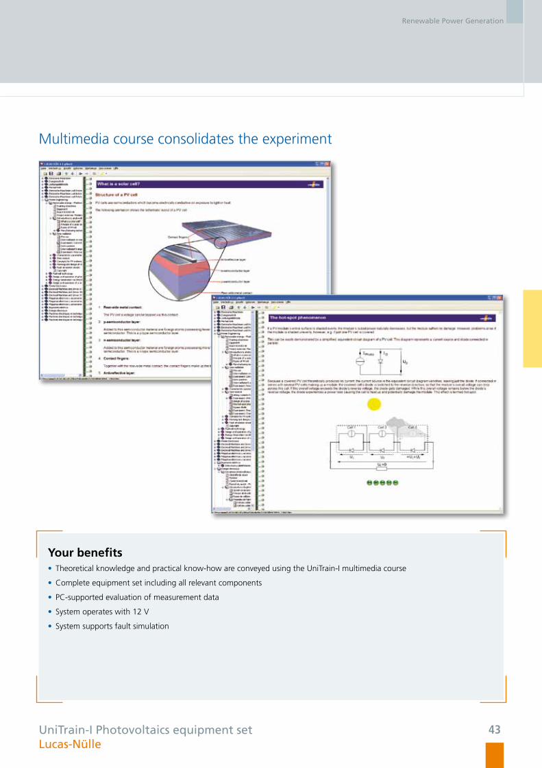
Multimedia course consolidates the experiment
Your benefits • Theoretical knowledge and practical know-how are conveyed using the UniTrain-I multimedia course
• Complete equipment set including all relevant components
• PC-supported evaluation of measurement data
• System operates with 12 V
• System supports fault simulation
UniTrain-I Photovoltaics equipment set Lucas-Nülle
Renewable Power Generation
43

Advanced Photovoltaics
Lucas-Nülle
Renewable Power Generation
44

EPH 2 equipment set Lucas-Nülle
Project Work with Industrial Components
Training contents Investigating solar modules • Testing the optimum alignment of solar modules
• Recording the characteristics of solar modules
• Investigating response to partial shading
• Investigating how bypass diodes operate
• Learning about various types of wiring for solar modules
Setting up photovoltaic systems for off-grid operation • Installing PV systems
• Setting up and testing an off-grid PV system in direct mode
• Setting up and testing an off-grid PV system in storage
mode
• Setting up and testing an off-grid PV system for generating
230-V alternating voltage
Setting up photovoltaic systems for grid-parallel operation• Installing, setting up and testing a PV system with network
feed
• Measuring the energy produced by a PV system
• Determining a grid-connected inverter‘s efficiency
• Investigating a PV system‘s response to mains failure
The training system permits realistic simulation of paths taken by the sun. Emulators make it possible to conduct practical experi-
ments in the laboratory without the sun.
Permitting PC-supported evaluation of measurement data, the advanced photovoltaics multimedia course is designed to convey both
theoretical information and practical know-how.
Sample experiment ”Advanced photovoltaics“ EPH 2
Renewable Power Generation
45

Advanced Photovoltaics
EPH 2 equipment set Lucas-Nülle
A Little Sunshine for your Lab
Interactive Lab Assistant• Step-by-step instructions in multimedia format
• Explanation of physical principles using easily comprehensible
animations
• Quiz and assessment tools for testing progress made during
the course
• PC-supported evaluation of measurement data
• Virtual measuring instruments can be started directly from the
experiment manual
Solar module with altitude emulator • The sun‘s angle can be adjusted as a function of position
(latitude), date and time
• The solar module‘s inclination can be adjusted
• 10-W polycrystalline solar module
• 500-W halogen lamp with dimmer
• Realistic emulation of the sun‘s path
Renewable Power Generation
46

EPH 2 equipment set Lucas-Nülle
Solar emulator • Three independent solar emulators permit experiments even
without sunlight
• Adjustable light intensity for each emulator
• Bypass diodes are included for connection into the circuits
• 120 VA power
Industrial components • Solar charge controller
• Off-grid inverter
• Grid-connected inverter
• Simple operation and investigation of industrial components
Your benefits • Theoretical knowledge and practical know-how are conveyed using the Interactive Lab Assistant
• Use of industrial components
• Flexible experimentation by means of a real solar module or solar simulation model
• PC-supported evaluation of measurement data
• Integration into energy technology systems
Renewable Power Generation
47

Wind Power Plants
Lucas-Nülle
Renewable Power Generation
48

Double-fed Induction Generator (DFIG)
Training contents • Understanding the design and operation of modern wind
power plants
• Exploring physical fundamentals from ”wind to shaft“
• Learning about different wind power plant concepts
• Setting up and operating a double-fed asynchronous wind
generator
• Operating the generator at varying wind force levels as well
as adjustable output voltages and frequencies
• Determining optimum operating points under changing
wind conditions
• Investigating responses to ”fault-ride-through“ grid mal-
functions
EWG 1 equipment set Lucas-Nülle
This equipment set is designed for investigating modern wind power plants incorporating double-fed induction generators. The wind
can be emulated realistically by means of a servo machine test stand and ”WindSim“ software. A PC can be connected for convenient
operation and visualization during the experiments. The associated multimedia course titled ”Interactive Lab Assistant“ imparts theory
besides supporting experiment procedures and evaluation of measurement data.
Sample experiment ”Wind power plant“ EWG 1
Renewable Power Generation
49
Wind Power Plants
EWG 1 equipment set Lucas-Nülle
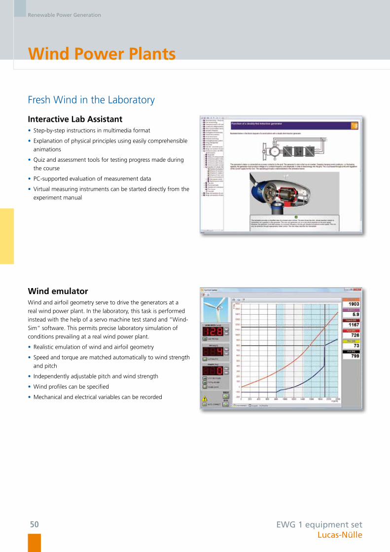
Fresh Wind in the Laboratory
Interactive Lab Assistant • Step-by-step instructions in multimedia format
• Explanation of physical principles using easily comprehensible
animations
• Quiz and assessment tools for testing progress made during
the course
• PC-supported evaluation of measurement data
• Virtual measuring instruments can be started directly from the
experiment manual
Wind emulator Wind and airfoil geometry serve to drive the generators at a
real wind power plant. In the laboratory, this task is performed
instead with the help of a servo machine test stand and ”Wind-
Sim“ software. This permits precise laboratory simulation of
conditions prevailing at a real wind power plant.
• Realistic emulation of wind and airfoil geometry
• Speed and torque are matched automatically to wind strength
and pitch
• Independently adjustable pitch and wind strength
• Wind profiles can be specified
• Mechanical and electrical variables can be recorded
Renewable Power Generation
50

EWG 1 equipment set Lucas-Nülle
Double-fed induction generator with control unit • Control unit with two controlled inverters
• Generator control in sub-synchronous and super-synchronous modes
• Integrated power switch for connecting the generator to the network
• Automatic control of active and apparent power, frequency and voltage
• Manual and automatic synchronization
• Measurement and display of all system variables
• Experiments on fault-ride-through
Your benefits • Theoretical knowledge and practical know-how are conveyed using the Interactive Lab Assistant
• Wind power and mechanical design of wind power plants can be emulated accurately and in detail using the servo machine
test stand
• The microcontroller-operated control unit for the double-fed induction generator permits user-friendly operation and
visualisation during experimentation
• State-of-the-art technology incorporating ”Fault-ride-through“
• Integration into energy technology systems
Renewable Power Generation
“Dynamic grid fault simulator““Control unit for double-fed induction generator“
“Fault-ride-through“
“Double-fed induction generator“
51

Small Wind Power Plants
Decentralized Electricity Supply
Training contents • Understanding the design and operation of small, modern
wind power plants
• Exploring physical fundamentals from ”wind to shaft“
• Learning about different wind power plant concepts
• Setting up and operating a small wind power generator
• Operation at varying wind forces in storage mode
• Energy storage
• System optimization
• Setting up an off-grid system for generating 230-V alter-
nating voltage
• Investigating hybrid systems for autonomous power supply
using wind power and photovoltaic systems
Small wind power plants with outputs ranging up to 5 kW are deployed today for decentralized electricity supply. These plants
generate direct voltages. The energy can be stored in batteries via charge controllers. Inverters produce alternating voltages to supply
electrical consumers in the grid.
The effects of wind power and the mechanical design of wind power plants can be emulated down to the last detail using the servo
machine test stand and the ”WindSim software“.
EWG 2 equipment set Lucas-Nülle
Sample experiment ”Small wind power plant“ EWG 2
Renewable Power Generation
52

EWG 2 equipment set Lucas-Nülle
Convincing Product Characteristics
Your benefits • Theoretical knowledge and practical know-how are conveyed using the Interactive Lab Assistant
• Wind power and mechanical design of wind power plants can be emulated accurately and in detail using the servo machine
test stand
• The laboratory generator‘s response is identical to that of one forming part of a real system
• The realistic, small wind power plant is suitable for outdoor operation and includes an integrable mast set
Interactive Lab Assistant • Step-by-step instructions in multimedia format
• Explanation of physical principles using easily comprehensible
animations
• Quiz and assessment tools for testing progress made during
the course
• PC-supported evaluation of measurement data
• Virtual measuring instruments can be started directly from the
experiment manual
Synchronous generator • Wind power and mechanical design of wind power plants can
be emulated accurately and in detail using the servo machine
test stand
• The laboratory generator‘s response is identical to that of one
forming part of a real system
• The small wind power plant is suitable for outdoor operation
Renewable Power Generation
53

Fuel Cell Technology
Design and Operation of Fuel Cells
Training contents • Functions and operating principles of fuel cells
• Recording the characteristics of a fuel cell
• Understanding the electrochemical processes of electrolysis
(Faraday’s first and second laws)
• Determining a fuel cell‘s Faraday and energy efficiencies
• Series and parallel connections of fuel cells
• Power aspects of fuel cells
• Functions and operating principles of electrolysers
• Recording an electrolyser‘s UI-characteristic
• Determining an electrolyser‘s Faraday and energy
efficiencies
Renewable energies are already considered a solution for dealing with expected energy shortages in the 21st century. The hydrogen-
based fuel cell is part of this solution. As a complementary technology, it will be used in future energy systems to generate clean
energy from renewable hydrogen.
UniTrain-I fuel cell equipment set Lucas-Nülle
Renewable Power Generation
54

Multimedia Course Consolidates the Experiment
UniTrain-I fuel cell equipment set Lucas-Nülle
Your benefits • Theoretical knowledge and practical know-how are conveyed using the Interactive Lab Assistant
• Compact device with PEM double fuel cell and PEM electrolyser including a gas storage element
• Safe handling of hydrogen
• 2V/2.5A for supplying power to the integrated electrolyser
• Diverse loads (lamps, fans)
• Variable load for recording characteristics
Renewable Power Generation
55

Advanced Fuel Cell Technology
Independent Electricity Supply with Fuel Cells
Training contents • Design and operation of a fuel cell
• Design and operation of an electrolyser
• Design and operation of a metal hydride storage cell
• Fuel cell‘s thermodynamics
• Fuel cell‘s characteristic and power curve
• Efficiency
• Components needed for autonomous power supply
• Power electronics and voltage conversion
Generation of electrical energy using fuel cells continues to develop into a significant area with diverse potential applications in elec-
trical and automotive engineering. Allowing safe handling of hydrogen and fuel cells, this experimentation system can be used for
a number of interesting investigations and is suited for demonstrations as well as practical lab work. The ”Interactive Lab Assistant“
includes animated theory, experiment guidelines and result evaluation fields.
EHY 1 equipment set Lucas-Nülle
Sample experiment ”50-VA fuel cell stack with loads“ EHY 1
Renewable Power Generation
56

Fuel cell stack • 50-VA stack
• Hydrogen supply flow meter
• Variable-speed fan for fuel cell ventilation
• Measurement of all relevant variables
Your benefits • Theoretical knowledge and practical know-how are conveyed using the ”Interactive Lab Assistant“
• Simple introduction to the subject of fuel cells
• Safe experimentation with hydrogen
• 50-VA fuel cell stack
• Connection for pressurized hydrogen tank
• High-performance electrolyser
• Wide variety of loads
• Variable load for recording characteristics
50-VA fuel cell stack
Interactive Lab Assistant • Step-by-step instructions in multimedia format
• Explanation of physical principles using easily comprehensible
animations
• Quiz and assessment tools for testing progress made during
the course
• PC-supported evaluation of measurement data
• Virtual measuring instruments can be started directly from the
experiment manual
EHY 1 equipment set Lucas-Nülle
Renewable Power Generation
57


Transformers
Three-phase Transformers (UniTrain-I) ..................................... 62
Investigating Transformers ..................................................... 63
Transformer Protection ........................................................... 64

Transforming and Protecting
In power engineering, transformers are used to connect the various voltage echelons of the power grid to each other. In transformer
stations, electricity from the regional distribution grid with a medium voltage level of 10 to 36 kV is transformed to supply power to
low-voltage end customers in the local grid where 400 V or 230 V is used. The key component of a system for converting voltages is
a transformer which also requires protective equipment. By carrying out hands-on measurements and fault simulations with the
training system, it is possible to gain an understanding of these complex systems in the classroom.
Lucas-Nülle
Transformers
Transformers
60

Training systems Our training systems cover the following topic areas:
• UniTrain-I “three-phase transformer“
• “Transformer investigations“ training panel system
• “Transformer protection“ training panel system
Transformer protection Differential protection for transformers (starting from approx.
1 MVA), combined with time overcurrent protection, can be
investigated using measurement techniques in normal operation,
fault occurrences in various winding circuit configurations (star,
delta), in various vector groups and as a function of star-point
treatment (floating, direct or earthed using earth coils). In the
case of differential currents, the tripping criteria is determined
based on characteristic sensitivity.
TransformersTransformers are electrical machines which serve to transform
alternating or three-phase currents to higher or lower voltages.
Three-phase transformers are of particular importance in the
transmission of electrical power.
In power engineering, transformers are used to connect diffe-
rent voltage levels within the power grid to each other.
Lucas-Nülle
Transformers
Source: SIEMENS
61

Three-phase Transformers
Models, Connection Types, Load Response
Transformers are electrical machines which serve to transform alternating or three-phase currents to higher or lower voltage levels.
Three-phase transformers are of special importance in the transmission of electrical power.
Training contents • Learning about the transformer principle and equivalent circuit diagram
• Investigating the load response of single-phase transformers in single- and four-quadrant operation
• Recording current and voltage with and without loads
• Investigating the transformation ratio
• Investigating loads for different vector groups
• Investigating different vector groups in connection with unbalanced loads
• Determining the short-circuit voltage
UniTrain-I three-phase transformer equipment set Lucas-Nülle
Transformers
62

Investigating Transformers
Transformers
In power engineering, transformers are used to connect different voltage levels of the power grid to each other. In the experiments,
the transformer’s equivalent circuit diagram is examined and its parameters are determined by means of measurements.
Training contents • Multiphase transformer operating at no-load and short-circuit
• Multiphase transformer with ohmic, inductive and capacitive load
• Determining zero impedance
• Investigating the transformation ratio
EUT equipment set Lucas-Nülle
Transformers
Sample experiment “Investigating transformers“ EUT
63

Transformer Protection
Transformer Differential Protection
Differential protection for transformers (starting from approx. 1 MVA), combined with time overcurrent protection, can be
investigated using measurement techniques in normal operation and fault occurrences in various winding circuit configurations
(star, delta), and in various vector groups and as a function of star-point treatment (floating, direct or earthed using earth coils).
Training contents • Detection and disconnection of transformer for internal faults
• Detection of peak inrush currents (RUSH) without disconnection
• Faulty tripping due to incorrectly dimensioned transformers
• Selection of tripping characteristics with differential currents taken into account
ETP 1 equipment set Lucas-Nülle
Transformers
Sample experiment “Transformer differential protection“ ETP 1
64

Time Overcurrent Protection
The time overcurrent protection supplements the safety protection measures contained in transformer differential protection.
It protects the transformers against short circuits outside the protection range and against overloading.
Training contents • Setting the parameters of the time overcurrent relay while taking the current transformation into consideration
• Detection of operating values for symmetrical and asymmetrical faults
• False tripping of the protective device during transformer’s switch-on response
• Transformer switch-on response in terms of protection
ETP 2 equipment set Lucas-Nülle
Transformers
Sample experiment “Time overcurrent protection“ ETP 2
65


Power Transmission
Investigation on Three-phase Transmission Lines ..................... 70
Parallel and Series Connection of Transmission Lines .............. 71
Transmission Line with Earth-fault Compensation ................... 72
Transmission Systems with a Synchronous Generator ............. 73
Three-phase Cables ................................................................ 74
Interconnected Network Grid with Cables and Overhead Lines ... 75
Line Protection ....................................................................... 76

Transmission Lines and Measures to Protect Them
High-voltage networks are usually operated with voltages in the region of 110 kV to 380 kV, whereby urban areas and large-scale
industrial facilities are supplied with 110 kV, and 380 kV is used for long-distance transmission lines. The line simulation system is
designed for operation at model voltages between 110 V and 380 V. Various line lengths can be selected via corresponding overlay
masks. Investigations can be made without a load, in a normal operating mode, in the presence of a short-circuit or earth fault or with
asymmetric faults, including shorts to earth, with and without compensation. The system also permits assembly of complex networks
by connecting the line simulation models in parallel or series. The voltage can be supplied via a fixed grid or synchronous generator.
Lucas-Nülle
Power Transmission
Power Transmission
68

Training systems Our training systems cover the following topics:
• Experiment panel group - ”Transmission lines“
• Experiment panel group - ”Line protection“
Lucas-Nülle
Innovative protection technology In practice, medium-voltage and high-voltage networks are
equipped with protective mechanisms connected via current and
voltage transformers.
• Use of compact, original relays incorporating cutting-edge
digital technology
• Use of industrial safety relays from prestigious international
manufacturers
• Monitoring of protective features by means of SCADA
(Supervisory Control and Data Acquisition)
• A relay test option permits the relays to be checked individually
High-voltage lines Your benefits:
• For your safety, the 380-kV transmission lines are investigated
and connected at a low-voltage level without detracting from
the characteristics of a real high-voltage line.
• Realistic simulation of a 380-kV transmission line with a length
of 300 km or 150 km
• Innovative switchover between line lengths by means of over-
lay masks
• Earth-fault compensation by means of a Petersen coil
• Ability to simulate symmetric and asymmetric faults
• Series and shunt compensation
Power Transmission
69

Transmission Lines
Investigations on Three-phase Transmission Lines
For your safety, the 380-kV transmission lines are investigated and connected at a low-voltage level without detracting from the cha-
racteristics of a real high-voltage line. This realistic simulation of a 380-kV transmission line switches over automatically between line
lengths of 300 km and 150 km once the overlay mask has been put into place.
Training contents • Voltage increases on open-circuit lines
• Voltage drop as a function of line length
• Voltage drop as a function of load
• Capacitive and inductive power losses on a line as a function of U and I
• Phase shift on a line
EUL 1 equipment set Lucas-Nülle
Sample experiment ”Investigations on three-phase lines“ EUL 1
Power Transmission
70

Parallel and Series Connection of Transmission Lines
Joint use of several line simulation models connected in parallel or series permits complex networks to be assembled.
Training contents • Distribution of power, voltage and current among parallel-connected lines of equal length
• Distribution of power, voltage and current among parallel-connected lines of unequal length
• Distribution of power, voltage and current among series-connected lines of equal length
• Distribution of power, voltage and current among series-connected lines of unequal length
• Load distribution, power flow
• Quantitative and qualitative evaluations of operational relationships
EUL 2 equipment set Lucas-Nülle
Sample experiment ”Investigations on parallel lines“ EUL 2
Power Transmission
71
Transmission Lines
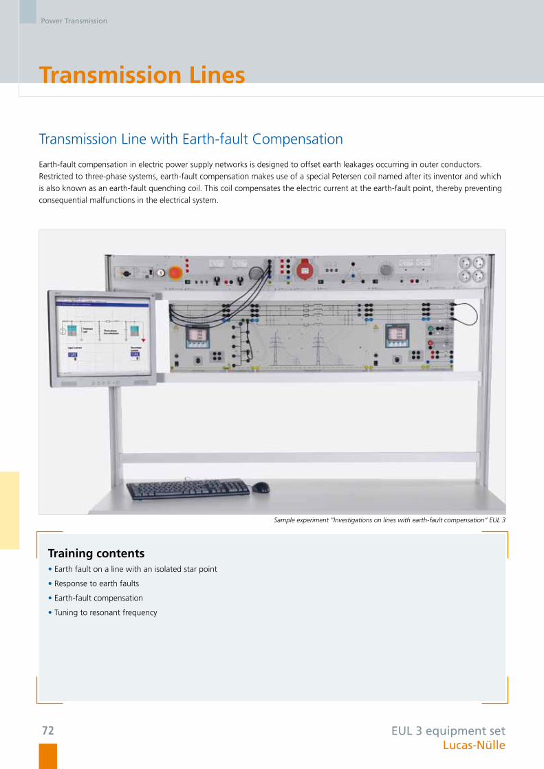
Transmission Line with Earth-fault Compensation
Earth-fault compensation in electric power supply networks is designed to offset earth leakages occurring in outer conductors.
Restricted to three-phase systems, earth-fault compensation makes use of a special Petersen coil named after its inventor and which
is also known as an earth-fault quenching coil. This coil compensates the electric current at the earth-fault point, thereby preventing
consequential malfunctions in the electrical system.
Training contents • Earth fault on a line with an isolated star point
• Response to earth faults
• Earth-fault compensation
• Tuning to resonant frequency
EUL 3 equipment set Lucas-Nülle
Sample experiment ”Investigations on lines with earth-fault compensation“ EUL 3
Power Transmission
72

Transmission Systems with a Synchronous Generator
The objective here is to measure characteristic power transmission parameters on simulated, three-phase, parallel-connected lines fed
via a fixed network or a generator, and perform quantitative as well as qualitative assessments of operational relationships.
Training contents • Power and current distribution in a line network fed by a generator
• Parallel operation of a generator and line via the network
• Control of active power feed
• Control of reactive power feed
EUL 4 equipment set Lucas-Nülle
Sample experiment ”Investigations on transmission systems with a synchronous generator“ EUL 4
Power Transmission
73

Transmission Lines
Three-phase Cables
A high-tension cable is one that is designed for use with high voltages. Cables of this type are used, among other things, for
transmitting large quantities of power in mains grids supplying electrical energy as an alternative to overhead lines. High-tension
cables can be categorised into the most important design types: earth cables, oil-filled cables, gas-pressure cables and plastic cables.
The objective of the experiments is to investigate the response of high-tension cables to a variety of operating conditions.
Training contents• Ferranti effect, loading capacity, critical length
• Resistive, inductive and combined resistive and inductive loading
• Compensation for a resistive-inductive load
• Determining zero impedance
• Symmetrical and asymmetrical short circuits
• Star (Y) point treatment and faults to ground
Sample experiment „Investigations on three-phase cables“ EUL 5
EUL 5 equipment set Lucas-Nülle
Power Transmission
74

Interconnected Network Grid with Cables and Overhead Lines
In electrical power supply grids, both cables and overhead transmission lines are used to transport energy. This experiment involves
investigating the properties of a power transmission line segment composed of both ground cables and overhead power lines.
Training contents• Differences between cables and overhead lines
• Investigation of lines from end to end:
- Overhead line-transformer-cables
- Cable-transformer-overhead line
• Observation of power losses from individual components
• Comparison between theory and practice
• Parameters for a voltage transformer station
Sample experiment „Investigations on interconnected network grids with cables and overhead lines“ EUL 6
EUL 6 equipment set Lucas-Nülle
Power Transmission
75

Line Protection
Overcurrent Time Protection for Lines
Items covered in this experiment series include overcurrent time relays whose time characteristic is independent of the current and
which are usually employed on single-wire (branch) lines.
Training contents • Designing and parameterising overcurrent time protection
• Determining the reset ratio in the case of single-, double- and triple-pole short circuit
• Determining a relay‘s shortest release time
• Checking a circuit breaker‘s release behaviour in the event of a failure
ELP 1 equipment set Lucas-Nülle
Sample experiment ”Overcurrent time protection for lines“ ELP 1
Power Transmission
76

Auxiliary Line Protection Equipment
ELP 2/3/4/5 equipment set Lucas-Nülle
ELP 2 Directional overcurrent time protection Training contents • Designing and parametrizing overcurrent time protection • Determining the reset ratio in the case of single-, double-
and triple-pole short circuit • Forward and reverse protection
ELP 3 Overvoltage and undervoltage protection Training contents • Determining rise and fall times • Determining the reset ratio • Determining the inherent time • Setting and testing various characteristics
ELP 4 Directional power protection Training contents • Determining rise and fall times • Implementing protection against reverse loads • Interaction with overcurrent time relays
ELP 5 Earth-fault detection Training contents • Measuring voltages in a sound, three-phase network • Measuring voltages in a three-phase network experiencing
earth faults • Determining rise and fall times • Determining the inherent time • Relay responses to momentary and permanent earth faults
Power Transmission
77

Line Protection
Protection of Parallel-connected Lines
Used mainly for protecting parallel-connected lines, the directional overcurrent protection relay is tested through fault simulation
here, besides being analyzed and investigated experimentally in terms of selectivity and speed.
Networked via a bus system, the protective relays can be operated and evaluated by means of the SCADA Power-LAB software.
Training contents • Protecting parallel-connected lines with different overcurrent time relays
• Parallel operation in the fault-free state
• Determining minimum response values for non-directional overcurrent time relays
• Determining directions of protection for directional overcurrent time relays
• Determining minimum response values for directional overcurrent time relays
• Time grading for overcurrent time relays
• Checking selectivity through combined overcurrent and directional measurements
• Networking protective measures
ELP 6 equipment set Lucas-Nülle
Sample experiment ”Protection of parallel lines“ ELP 6
Power Transmission
78

High-speed Distance Protection
Various faults can be analyzed in the case of the high-speed distance protection relay employed for more complex networks. This
type of protection permits faults to be isolated in dependence of their distance. Besides preparation of a grading schedule, selectivity
can be set and tested in a practical manner.
Training contents • Preparation of a grading schedule
• Relay parameterisation
• Operating a distance protection relay with current and voltage transformers
• Tests of triggering characteristics in the event of various faults inside and outside the line‘s protective domain
• Tests of triggering characteristics in the event of various faults inside and outside the protective domain:
- Distance protection
- Overcurrent time protection
- Voltage protection
- Frequency protection
ELP 7 equipment set Lucas-Nülle
Sample experiment ”High-speed distance protection“ ELP 7
Power Transmission
79


Electric Power Distribution
Three-phase Double Busbar System ........................................ 84
Overcurrent Protection for Busbars ......................................... 85

Busbars at high-voltage switching stations
Electrical power at large switching stations is distributed almost exclusively using double busbar systems. These stations incorporate
switching matrices for connecting the two busbars, the incoming and outgoing feeder cubicles as well as the measurement fields.
The incoming and outgoing feeder cubicles as well as the switching matrices are furnished with circuit breakers and one disconnector
for each busbar terminal. For safety reasons, a particular switching logic must be strictly adhered to here. The double busbar model
incorporates all functions of practical relevance. Integrated instruments for measuring currents and voltages permit direct analyses of
switching operations.
Lucas-Nülle
Electric Power Distribution
Electric Power Distribution
82

Training systems Our training systems cover the following topics:
• Experiment panel group - ”Three-phase double busbar system“
• Experiment panel group - ”Overcurrent protection for busbars“
Lucas-Nülle
SCADADevices are monitored and controlled by means of the SCADA
(Supervisory Control and Data Acquisition) system. All devices
belonging to Lucas-Nülle‘s energy technology programme can
be arranged as desktop icons and linked together. Measurement
values and operating states are indicated. Important parameters
and signals can be controlled via the software. Measurement
values and operating states can be recorded, displayed as
functions of time, and analyzed. Automatic switchover between
busbars can be performed via the PC.
Double busbar systems The compact modules named ”Incoming and outgoing feeder
cubicles“ and ”Switching matrix“ offer the following advan-
tages:
• Flexible arrangement of the various fields
• Operation and monitoring from a PC
• Networking capability thanks to an RS-485 interface
• Manual operation
• Integrated microcontroller for preventing incorrect operation
• Registration of all characteristic parameters such as current,
voltage and switching states
Electric Power Distribution
83

Three-phase Double Busbar System
Central Distribution and Control
Busbars serve as central distributors of electrical energy, all incoming and outgoing lines being connected to the busbars. Busbars
comprise incoming and outgoing feeder cubicles, switching matrices and converter panels.
As part of Lucas-Nülle‘s equipment sets, these functions are grouped into switching fields containing circuit breakers, disconnectors
and data loggers.
Training contents • Basic circuits of a three-pole, double busbar system
• Three-phase, double busbar system with load
• Busbar changeover without interruption of the branch
• Preparation of algorithms for various switching operations
• Busbar coupling
EPD equipment set Lucas-Nülle
Sample experiment ”Three-phase double busbar system“ EPD
Electric Power Distribution
84

Overcurrent Protection for Busbars
Due to the busbar‘s differential protection, the input and output currents are added up via a current transformer. In the case of
differential currents, the characteristic sensitivity serves as a basis for determining trigger criteria.
Training contents • Registration of currents in normal operating mode
• Registration of currents in the event of single-, double- or triple-pole short circuit
• Faults outside the protective domain
• Response of protective equipment to faults both external and internal to the switchgear
EDP equipment set Lucas-Nülle
Sample experiment ”Overcurrent protection for busbars“ EDP
Electric Power Distribution
85


Energy Management
Complex Loads, Power Consumption Measurement
and Peak Load Monitoring ..................................................... 90
Dynamic Loads ....................................................................... 91
Manual and Automatic Compensation of Reactive Power ...... 92
Energy-efficient drives ............................................................ 93
Protection of Electric Loads .................................................... 94

Intelligent networks and loads
For economic and environmental reasons, a rational use of energy is becoming increasingly important. Exercises on manual and
automatic compensation of reactive power as well as experiments on reducing peak loads through measurements with active-current
and maximum-demand meters demonstrate how the load on a mains supply network can be reduced and evenly distributed over a
24-hour period. An analysis of the power supply grid and connected consumers (loads) is necessary for effective use of the involved
measurement techniques. Accordingly, each experiment permits a detailed investigation of static, dynamic, symmetric and asym-
metric loads. Protection of electrical consumers is another important training subject.
Lucas-Nülle
Energy Management
Energy Management
88

Training systems Our training systems cover the following topics:
• Experiment panel group - ”Complex loads, energy consumpti-
on measurement and peak load monitoring“
• Experiment panel group - ”Dynamic loads“
• Experiment panel group - ”Manual and automatic compensa-
tion of reactive power“
• Experiment panel group - ”Protection of electric machines“
• Experiment panel group - ”Motor protection / management“
Lucas-Nülle
Protecting electrical consumers Malfunctions in electrical systems resulting from short circuits,
overload etc. must be prevented or at least restricted by means
of appropriate protective measures, and the faulty devices
disconnected selectively from the network. For the protective
features to be properly implemented and correctly dimensioned,
it is necessary to know their trigger characteristics and times, as
well as their operational characteristics. This experiment series
provides detailed treatment of how to protect three-phase
motors by means of a motor protection switch, temperature
monitoring in the coils, and triggering via a thermistor device.
An experiment on full motor protection with a digital device can
also be conducted. The handling and parametrization of the
digital motor protection device are the focus of training in this
experiment.
Smart meteringAll energy technology kits contain intelligent measuring devices
possessing a variety of communication interfaces (e.g. LAN,
RS485, USB) and control elements. Consequently, consumers
can not only be monitored, but also intelligently controlled. An
automatic load management program can be realized with the
features listed below:
• Monitoring of the specified power limit
• Enabling and disabling of consumers in accordance with a
defined priority list
• Activation of consumers during low-load intervals
Energy Management
Source: SIEMENS
89
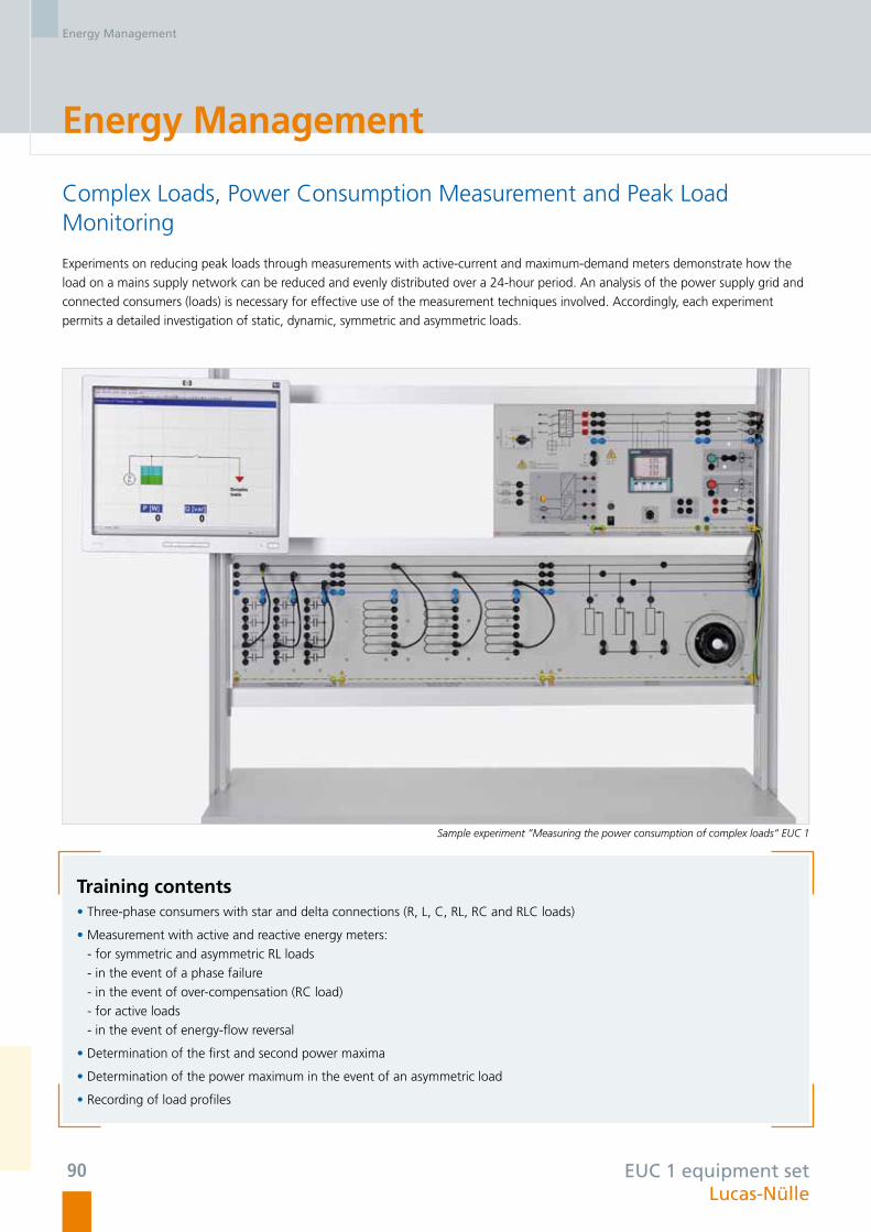
Energy Management
Complex Loads, Power Consumption Measurement and Peak Load Monitoring
Experiments on reducing peak loads through measurements with active-current and maximum-demand meters demonstrate how the
load on a mains supply network can be reduced and evenly distributed over a 24-hour period. An analysis of the power supply grid and
connected consumers (loads) is necessary for effective use of the measurement techniques involved. Accordingly, each experiment
permits a detailed investigation of static, dynamic, symmetric and asymmetric loads.
Training contents • Three-phase consumers with star and delta connections (R, L, C, RL, RC and RLC loads)
• Measurement with active and reactive energy meters:
- for symmetric and asymmetric RL loads
- in the event of a phase failure
- in the event of over-compensation (RC load)
- for active loads
- in the event of energy-flow reversal
• Determination of the first and second power maxima
• Determination of the power maximum in the event of an asymmetric load
• Recording of load profiles
EUC 1 equipment set Lucas-Nülle
Sample experiment ”Measuring the power consumption of complex loads“ EUC 1
Energy Management
90

Dynamic Loads
In this case, a three-phase asynchronous motor coupled with the servo machine test stand is used as a dynamic load. The active and
reactive powers (motor‘s cos-phi) depend on the motor load and are therefore not constant. The servo machine test stand can also be
used to drive the asynchronous motor, thereby feeding active power into the three-phase network.
Training contents • Dynamic, three-phase load (asynchronous motor)
• Power measurement in the case of energy-flow reversal
EUC 2 equipment set Lucas-Nülle
Sample experiment ”Investigations on dynamic loads“ EUC 2
Energy Management
91
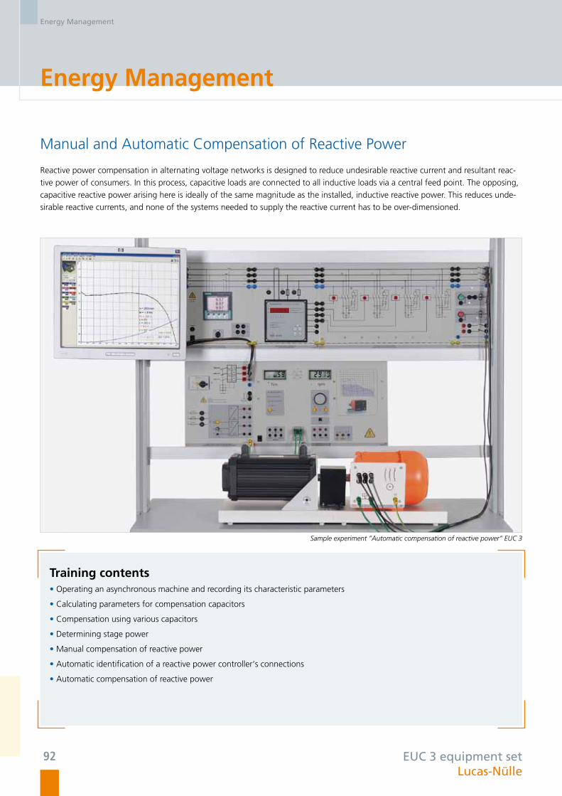
Energy Management
Manual and Automatic Compensation of Reactive Power
Reactive power compensation in alternating voltage networks is designed to reduce undesirable reactive current and resultant reac-
tive power of consumers. In this process, capacitive loads are connected to all inductive loads via a central feed point. The opposing,
capacitive reactive power arising here is ideally of the same magnitude as the installed, inductive reactive power. This reduces unde-
sirable reactive currents, and none of the systems needed to supply the reactive current has to be over-dimensioned.
Training contents • Operating an asynchronous machine and recording its characteristic parameters
• Calculating parameters for compensation capacitors
• Compensation using various capacitors
• Determining stage power
• Manual compensation of reactive power
• Automatic identification of a reactive power controller‘s connections
• Automatic compensation of reactive power
EUC 3 equipment set Lucas-Nülle
Sample experiment ”Automatic compensation of reactive power“ EUC 3
Energy Management
92

Energy Management
EEM 11 equipment set Lucas-Nülle
In Germany, about half the electrical energy the country needs is used by industry. The main consumers are electrical drives. These account for some 70% of industrial electricity consumption. Optimising electrical drives can therefore help to save costs and protect resources. In optimising industrial plant operated by electricity, it is always necessary to examine the whole drive system since there are various factors which affect the energy efficiency of drive motors, such as the intelligent use of electrical power, improvement of effi-ciency, automatic speed control and energy recovery.
“Energy-efficient frequency converter drives” training system consisting of an optimum-efficiency motor, frequency converter and servo machine test stand EEM11.3
Training contentsEnergy-efficient drive design• Identifying losses in a drive system
• Investigation of motor parameters by means of
characteristic curves
• Optimisation of system efficiency by selecting the
appropriate motor
• Indirect determination of loading on a motor
Use of energy-saving motors:• Design and function of energy-saving motors
• Energy efficiency classes for motors
• Comparison between an energy-efficient motor and a
standard motor
• Characteristic parameters for energy-saving motors
• Determination of savings potential
Energy-efficient frequency converter drives:• Setting up variable-speed drives
• Investigation of how various parameters affect operating
response
• Energy-efficient matching of operating points
• Creating energy-efficient motion profiles
• Observation of overall system efficiency
Energy-efficient drives
93

EDT 51 equipment set Lucas-Nülle
Protection of Electric Loads
Effective Motor Protection – Preventive Maintenance
Used as part of modern automation technology, motor management systems make it possible to optimally protect, control and monitor
drives and related equipment. Parameters such as motor temperature, voltage and current can be registered in this way. Linkage to
higher-level process automation via field bus systems (e.g. PROFIBUS) makes the motor‘s operation more transparent. As a result, the
motor‘s utilization level and energy consumption can be monitored without having to perform in-situ measurements.
Sample experiment ”Motor management relay“ EDT 51
Training contents • PC-supported operation of a motor management system
• Programming of functions such as direct start, star-delta start, reversible-pole motor start, motor protection
• Parametrization of overload variables and switch-off response under various loads
• Measurement of dynamic processes during starting
• Preventive maintenance
Energy Management
94

EEM 4.6 equipment set Lucas-Nülle
Three-phase Asynchronous Machines
Squirrel-cage motors are designed for operation under constant load conditions. Changes in load or excessively high starting currents
can cause such motors to heat up beyond permitted levels. Sensors are therefore used to monitor the motor‘s temperature and
current consumption.
As required, these sensors activate protective features such as the motor protection switch, motor protection relay and thermistor
relay.
Sample experiment ”Protection of electric machines“ EEM 4.6
Training contents • Selecting, installing and setting various motor protection systems
• Motor protection switch
• Motor protection relay
• Thermistor protection
• Effect of various operating modes on motor heating
• Trigger characteristics of protective systems
• Protection against impermissible load states
Energy Management
95

Local grid
Industrial consumer Industrial consumer
Wind power plant
Smart-grid control centre
Solar power plant
Municipal grid

Smart Grid
Smart Grid: Control Centre .................................................. 102
Smart Grid: Energy Management ......................................... 103
Energy Generators in a Smart Grid ....................................... 104
Energy Storage Facilities in a Smart Grid ............................... 105

Smart Grid
Ideally Equipped for the Future:A Smart Grid in a Power Engineering Laboratory
In future, new technologies will better equip the power supply grid for the demands of a new era. More flexible network management
should make the increasing contribution from renewable energies more compatible with the conventional power station infrastructure.
The variety in the nature and number of such decentralised power generation systems requires a new way of running the power grid, a
so-called intelligent network or “smart grid”:
• Improved coordination between energy consumption and generation
• Use of modern information technology, such as the Internet, sensors, control systems and wireless communications equipment
• “Smart metering” – digital electricity meters measure power consumption by end users of the power grid.
• Shifting of household consumption away from peak-load periods
• Automatic starting of flexible applications, such as washing laundry, by energy suppliers themselves outside of peak times
Lucas-Nülle
Smart Grid
98

Smart measuring instruments:
• Smart measuring instruments with a variety of controls and
ability to communicate via various interfaces
(e.g. LAN, RS485, USB)
• Measurement and control of all relevant variables by means of
smart meters and high-powered switches
• SCADA Net-compatible: Display and control of measure-
ments and status from any PC on the network
SCADA Software in a Smart Grid
• Implementation, control and analysis of complex, intelligent
grids (smart grids)
• SCADA software adapted for education
• SCADA PLC: Integrated software PLC (IEC 61131)
• SCADA Logger: Recording, display, evaluation and export of
all values recorded in a given period
• SCADA Designer: Symbolic layout of all equipment from
Lucas-Nülle’s energy supply range on a user interface
• SCADA Viewer: Display and control of measurements and
status from all computers on the network
• SCADA Net: The client/server concept makes it possible to re-
motely access systems on the smart grid from multiple (student)
PCs at the same time.
• SCADA Panel Designer: Design your own control panels
Modular Integration of Regenerative Power Generation into a Smart Grid:
• Photovoltaics
• Wind power
• Storage of electrical energy by means of pumped storage
hydroelectricity
• Conventional power generation
• Transmission and distribution
• Energy management (coordination of dynamic power genera
tion and consumption)
Lucas-Nülle
Smart Grid
99

“Smart Grid” – Intelligent Mains Networks
The Networked Power Engineering Laboratory
These equipment sets allow training systems covering the generation, transmission and management of electrical energy as well as
the protective equipment required to be combined, both electrically and by means of computer networks. All relevant values can be
measured via the Smart Grid control centre and the necessary switching operations undertaken. This makes it possible to study the
influence of renewable energy generation in laboratories. A host of scenarios can be emulated, such as the following:
• Charging of electric cars when there is a surplus of wind energy
• Storage of excess energy in pumped-storage hydroelectric plants
• Disconnection of consumers to reduce peak load
• Compensating for energy deficits by means of pumped-storage hydroelectric power
The SCADA software allows the whole system to be observed or controlled from any work station
PhotovoltaicsHydroelectric power plant
Wind power plant
Lucas-Nülle
Smart Grid
100

Lucas-Nülle photovoltaic systems
• Power: 89 kW max.
• 450 photovoltaic modules
(215 W each)
• Saves 55 tonnes of CO2
per year
SMART Grid control centre
Energy management
External energy sources can also be integrated
Lucas-Nülle
Smart Grid
101

“Smart Grid” – Intelligent Mains Networks
This equipment set forms the core for a smart grid in a power generation lab. In addition to generation, transmission and distribution
of energy, the SCADA software records all relevant values and handles the requisite switching operations. This can be done manually or
automatically by means of a software PLC system.
Example experiment “Smart grid: Generation, distribution and transmission of electrical power ESG 1.1”
Training contentsThree-phase double busbar system• Basic circuits for a three-pole double busbar system
• Three-phase double busbar systems with load
• Busbar transfer without interrupting feed
• Finding switching algorithms for various switching
operations
• Busbar coupling
Investigations on three-phase transmission lines• Voltage rises in unloaded transmission lines
• Voltage drop as a function of line length
• Voltage drop as a function of cos phi
• Capacitive and inductive power losses in a transmission line
as a function of voltage and current
• Phase-shift along the line
Definite time overcurrent protection for lines• Rating and parameters for definite time overcurrent
protection
• Determine returning ratio (differential) for short circuits
involving one, two or three poles
Smart Grid – Control Centre
ESG 1.1 equipment setLucas-Nülle
Smart Grid
102

Smart Grid – Energy Management
Example experiment “Smart grid: Energy management ESG 1.2“
Training contentsComplex loads, metering of electricity consumption and monitoring of peak load• Three-phase load in star and delta configurations (R, L, C,
RL, RC or RLC load)
• Measurements with active and reactive work meters
Dynamic loads• Dynamic three-phase loads (asynchronous motors)
• Power measurement when energy is being fed in and
fed out
Manual and automatic reactive power compensation• Putting asynchronous machines into operation and record-
ing parameters
• Manual reactive power compensation
• Automatic reactive power compensation
The topic of energy management includes switching off consumers to reduce peak loads as well as reactive load compensation for
reducing losses along transmission lines. The asynchronous machine in the set can be dynamically loaded by means of the machine test
stand in order to simulate variable changes in load over time on the entire mains grid. Such changes in load are recorded by the Smart
Grid Control Centre so that suitable remedial action can be taken to keep the grid stable.
ESG 1.2 equipment set Lucas-Nülle
Smart Grid
103

These supplementary equipment sets for power engineering can optionally be combined, either individually or in conjunction with the
“Smart Grid” experiment set ESG 1. This makes it possible to conduct extensive investigations in a smart grid.
Example experiment “Smart grid supplement to ESG 1: Energy generators in a smart grid“
Training contents Wind power plants, EWG 1• Operating a generator under changing wind speed plus
control of output voltage and frequency
• Determining optimum operating points under changing
wind conditions
Photovoltaic systems operating parallel to the main grid, EPH 2• Setup and testing of photovoltaic systems with mains feed
• Measurement of energy generated by a photovoltaic sys-
tem
• Determining efficiency of mains power inverters
• Investigation of the response of a photovoltaic system to
mains power failures
Synchronous generators, EUG• Generator control and synchronisation
• Manually operated synchronisation circuits
• Automatic synchronisation circuits
• Automatic power correction
• Automatic power factor correction
“Smart Grid” – Intelligent Mains Networks
Energy Generators in a Smart Grid
Supplementary set for ESG 1Lucas-Nülle
Smart Grid
104

Pumped-storage Hydroelectricity
Example experiment “Smart grid supplement to ESG 1: Pumped-storage hydroelectric plant EUG 3“
Training contents• How pumped storage hydroelectricity works
• Starting and synchronisation of synchronous machines
• Manual control of power in generator or motor modes
• Semi-automatic active and reactive power control
• Pumped storage hydroelectricity in a smart grid
• Fully automatic compensation for active and reactive power as measured externally
• Open- and closed-loop control of the system via SCADA
In pumped-storage hydroelectric plants, electrical energy is converted into potential energy using stored water and then reconverted to
electrical power for feeding back to the mains. Such stations have turned into essential and indispensable energy storage systems for
high-quality smart grids due to the increasing use of renewable energy generation. The pumped-storage hydroelectricity equipment set
adds electricity storage to the experiments on smart grids with renewable energy generation.
Supplementary set for ESG 1 Lucas-Nülle
Smart Grid
105

Lucas-Nülle
“
”
Decisive Product Benefits
… ensure Long-term Customer Satisfaction
Herr Prof. Guntram Schultz, Dean at the University of Applied Sciences in Karlsruhe, Department of Electrical Engineering and Information Technology:
“I am a huge fan of electrical power engineering from Lucas-Nülle. The extensive programme facilitates innumerable analyses of such
fields as power generation and distribution technology – including mains protection – as well as energy consumption.
Thanks to the modularly designed three-phase training panel system, system relationships can be explored step by step within the
experiment.
Moreover, the high potential for expandability facilitates seamless integration of renewable energies into conventional power engine-
ering. No other manufacturer provides a system which demonstrates such flexibility and which can be reconfigured again and again
depending on requirements.
A particular advantage is in my view the consistent use of the electrical scale of 1:1000 which enables measurement findings to be
compared directly with real measurements. Realistic line simulations at the variable length facilitate the deployment of conventional in-
dustrial equipment for reality-based project work in a safe lab environment. The SCADA system enables optimal experiment monitoring
and control while data evaluation processes are second to none. The materials which come in the form of multi-media courses are very
attractively designed and are popular with students.
Meanwhile the quality of the individual experiment components, combined with a proven didactic concept, are the factors which
appeal most to lecturers.
All of this is by way of explaining why we chose Lucas-Nülle. Using the programme as a whole, we can plan the entire electrical power
engineering course systematically while familiarising students with typical industrial applications in a focussed manner. ”
106

The Whole is Greaterthan the Sum of its Parts
2
Individual consultation with Lucas-Nülle
Do you require comprehensive advice or a firm offer?
Then you can contact us using any of the following means:
Tel.: +49 2273 567-0
Fax: +49 2273 567-39
Lucas-Nülle is a byword for custom occupational training courses in all of the following areas:
Ask us for detailed information using any of the given methods of contact.
Our employees will be happy to advise you.
Further information on our products can be found at the following web addresses:
www.lucas-nuelle.com
Electrical Wiring Electropneumatics and Hydraulics
Electrical Power Supply Technology Measurement and Instrumentation Technology
Power Electronics, Electrical Machines, Drive Technology
Renewable Energies
Microcomputers
Refrigeration and Air-conditioning Technology
Fundamentals of Electrical Engineering and Electronics
Automation
Communications Technology Automotive Technology
Control Technology Laboratory Systems
107

Lucas-Nülle GmbHSiemensstraße 2 · D-50170 Kerpen-Sindorf · Germany
Telephone: +49 2273 567-0 · Fax: +49 2273 567-39
www.lucas-nuelle.com
Ref.
-No.
: P5
147
Trai
ning
Sys
tem
s fo
r El
ectr
ical
Pow
er E
ngin
eerin
g 10
/12-
3GB
(Prin
ted
in G
erm
any)
Subj
ect
to t
echn
ical
alte
ratio
ns.